

Page 1
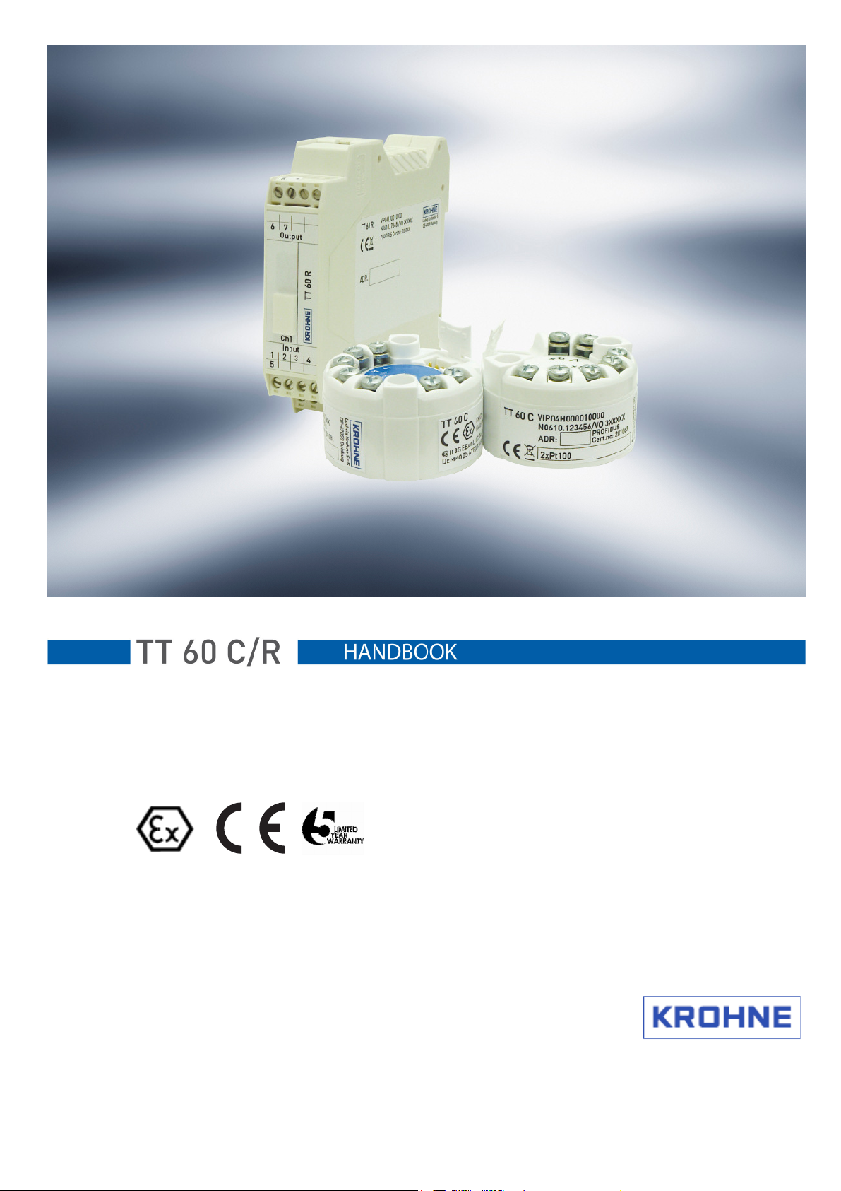
Two-wire transmitter with ProfiBus-PA® interface
© KROHNE 11/2010 – 4000754401 – MA OPTITEMP TT60CR R01 en
Page 2

Copyright
Copyright
CopyrightCopyright
All rights reserved. Any duplication of this documentation or extracts thereof by any means is
prohibited without prior written consent from KROHNE Messtechnik GmbH.
Subject to change without notice.
Copyright 2010 by
KROHNE Messtechnik GmbH • Ludwig-Krohne-Straße 5 • 47058 Duisburg
Tel. +49 (203) 301-0
11/2010 – 4000754401 – MA OPTITEMP TT60CR R01 en www.krohne.com
2
Page 3

1111 Safety information
2222 Device description
3333 Installation
4444 Electrical connections
5555 Operation
6666 Technical data
7777 Service
Safety information ................................
Safety informationSafety information
1.1 Intended use ......................................................................................................... 4
1.2 Product liability and guarantee ............................................................................ 4
1.3 Certifications ........................................................................................................ 5
1.3.1 Certifications, PC connection cable, Type A ................................................................5
1.4 Manufacturer's safety instructions ...................................................................... 5
1.4.1 Notes about the documentation ...................................................................................5
1.4.2 Symbol conventions ......................................................................................................6
Device description ................................
Device descriptionDevice description
Installation ................................
InstallationInstallation
3.1 TT 60 C installation ............................................................................................... 8
3.2 TT 60 R installation..............................................................................................10
Electrical connections ................................
Electrical connectionsElectrical connections
4.1 Safety instructions...............................................................................................11
4.2 Connections .........................................................................................................12
4.3 ProfiBus connection ............................................................................................13
4.3.1 Shielding and grounding .............................................................................................13
4.3.2 Cable parameters for areas with potentially explosive atmospheres .....................14
4.3.3 Terminator...................................................................................................................15
4.3.4 ProfiBus architecture .................................................................................................15
4.4 TT 60 C connection diagram................................................................................16
4.5 TT 60 C connection diagram ...........................................................................17
4.6 TT 60 R connection diagram................................................................................18
Operation................................
OperationOperation
5.1 Connection using the KROHNE PC configuration set..........................................19
5.2 General ................................................................................................................20
5.2.1 Smart Sense ................................................................................................................21
5.2.2 Monitoring of sensor aging.........................................................................................21
Technical data ................................
Technical dataTechnical data
6.1 TT 60 C specifications..........................................................................................22
6.1.1 Technical data .............................................................................................................22
6.1.2 TT 60 C dimensions .....................................................................................................23
6.1.3 Data inputs and outputs..............................................................................................23
6.1.4 Ambient temperature data for areas with potentially explosive atmospheres.......23
6.2 TT 60 C specifications .................................................................................... 24
6.2.1 Technical data .............................................................................................................24
6.2.2 TT 60 C dimensions .............................................................................................25
6.2.3 Data inputs and outputs..............................................................................................25
6.2.4 Ambient temperature data for areas with potentially explosive atmospheres,......25
6.3 TT 60 R specifications..........................................................................................26
6.3.1 Technical data .............................................................................................................26
6.3.2 TT 60 R dimensions .....................................................................................................27
Service................................
ServiceService
7.1 Ordering information...........................................................................................28
................................................................
................................................................
................................................................
................................................................
................................................................
................................................................
................................................................
................................................................
................................................................
................................................................
...............................................................
................................................................
................................................................
................................................................
................................................................
................................................................
................................................................
................................................................
................................................................
................................................................
....................................................
................................................................
....................................................
................................................................
...............................8888
..............................................................
............................................
................................................................
................................19
................................................................
........................................................
................................................................
....................................
................................................................
....................4444
........................................
....................7777
........................................
............11
........................
........................22
................................................
11
1111
19
1919
22
2222
....28
28
........
2828
11/2010 – 4000754401 – MA OPTITEMP TT60CR R01 en www.krohne.com
3
Page 4
1 Safety information
1.1 Intended use
The TT 60 C is a two-wire universal transmitter with ProfiBus-PA® interface for temperature
and other measurement applications. It is intended for installation in a B connection head or
larger according to DIN 43729.
The TT 60 C is optionally available in an intrinsically safe version for installation in areas with
potentially explosive atmospheres. These devices are labeled with the Ex symbol .
The TT 60 R is an intelligent, two-wire universal transmitter with ProfiBus-PA® interface for
temperature and other measurement applications.
It is only intended for installation on a top-hat rail according to DIN EN 50022.
ATTENTION!
ATTENTION!
ATTENTION!ATTENTION!
Responsibility for the use of the measurement devices with regard to suitability, intended use
and area of application lies solely with the user.
The manufacturer shall not be liable for damage resulting from improper use or use for other
than the intended purpose.
1.2 Product liability and guarantee
Use for other than the intended purpose or improper installation and operation may lead to loss
of the guarantee. The guarantee shall likewise be void if the device is damaged or its function
otherwise impaired.
KROHNE Messtechnik GmbH hereby guarantees that the product will be free of material and
workmanship defects for a period of five (5) years from the date of delivery ("limited
guarantee"). This limited guarantee refers to repairs or exchanges, and is only valid for the first
end user of the product.
The "General conditions of sale" forming the basis of the purchase contract are also applicable.
11/2010 – 4000754401 – MA OPTITEMP TT60CR R01 en www.krohne.com
4
Page 5

1.3 Certifications
Approval Demko 06 ATEX 141336X
Approval Demko 06 ATEX 141336X
Approval Demko 06 ATEX 141336XApproval Demko 06 ATEX 141336X
TT 60 C:
TT 60 C: CE
TT 60 C: TT 60 C:
TT 60 C Ex:
TT 60 C Ex: CE 0102
TT 60 C Ex: TT 60 C Ex:
IMPORTANT NOTE
IMPORTANT NOTE!
IMPORTANT NOTEIMPORTANT NOTE
See also the ATEX certificate "Special conditions for safe use".
The measuring device complies with the statutory requirements of the following EC directives:
The manufacturer's declaration can be viewed on the Internet at
http://www.krohne.com/html/dlc/index.shtml.
KROHNE Messtechnik GmbH certifies successful testing of the product by applying the CE
mark.
CE II 3G EEx nL I
CE CE
CE 0102 II 1G Ex ia IIC
CE 0102CE 0102
II 3G EEx nL IIC
II 3G EEx nL I II 3G EEx nL I
II 1G Ex ia IIC
II 1G Ex ia IIC II 1G Ex ia IIC
IC
ICIC
1.3.1 Certifications, PC connection cable, Type A
Approval Demko 06 ATEX 141337X
1.4 Manufacturer's safety instructions
The measuring device has been built and tested in accordance with the current state of the art,
and complies with the relevant safety standards.
However, dangers may arise from improper use or use for other than the intended purpose. For
this reason, observe all of the safety instructions in this document carefully.
1.4.1 Notes about the documentation
In addition to the safety rules and industrial safety regulations in this documentation, national
and regional safety rules and industrial safety regulations must also be observed.
11/2010 – 4000754401 – MA OPTITEMP TT60CR R01 en www.krohne.com
5
Page 6
1.4.2 Symbol conventions
For greater clarity, the following symbols are used in this documentation:
DANGER!, WARNING!, ATTENTION!, CAUTION!
DANGER!, WARNING!, ATTENTION!, CAUTION!
DANGER!, WARNING!, ATTENTION!, CAUTION!DANGER!, WARNING!, ATTENTION!, CAUTION!
This symbol indicates general dangers.
All warnings must always be observed. Even partial failure on your part to observe them can
lead to serious damage to health, damage to the device or to the user's system components.
DANGER!
DANGER!
DANGER!DANGER!
This symbol is used to identify dangers when working with electric current.
Work on the device's electrical and electronic components may only be performed by qualified
personnel with the appropriate training.
DANGER!
DANGER!
DANGER!DANGER!
This symbol indicates dangers in areas with potentially explosive atmospheres, for example
those which may arise during installation and operation of explosion-proof devices.
Special regulations apply for use in areas with potentially explosive atmospheres; these must
always be observed in order to ensure safe use in such areas. Installation, set-up, operation
and maintenance of the device may only be performed by qualified persons with training in
explosion protection.
Important note!, Note!, Information!
Important note!, Note!, Information!
Important note!, Note!, Information!Important note!, Note!, Information!
This symbol identifies important notes and information for working with the device.
Legal note!
Legal note!
Legal note!Legal note!
This symbol identifies references to legal and normative regulations.
Action
Action
ActionAction
This symbol identifies all instructions for actions; the actions must be performed by the user
in the specified sequence.
Effect
Effect
EffectEffect
This symbol identifies all of the important effects of the previous actions.
11/2010 – 4000754401 – MA OPTITEMP TT60CR R01 en www.krohne.com
6
Page 7

2 Device description
The KROHNE TT 60 C/R is two-wire universal transmitter with ProfiBus-PA® interface for
o Temperature measurements with resistance thermometers
o Temperature measurements with thermocouples
o Temperature differential measurements with resistance thermometers
o Measurements with potentiometers
o Voltage measurements in a range from -10...1000 mV
The transmitter supports two input signals, thus allowing differential, average and redundant
measurements and monitoring of sensor aging.
The TT 60 C is optionally available for areas with potentially explosive atmospheres.
The two-wire universal transmitter TT 60 C is designed for installation in a B connection head
according to DIN 43729 or larger.
The two-wire universal transmitter TT 60 R is designed for installation on a top-hat rail
according to DIN EN 50022 .
The output of all versions of the TT 60 complies with the latest ProfiBus PA® standard for
temperature measuring transducers, i.e. Profile 3.0, Class A and B.
The transmitter can be configured using ProfiBus-PA® or an IBM-compatible PC. Configuration
of the transmitter using an IBM-compatible PC requires the "ProfiSoft" software.
The Windows-based "ProfiSoft" software can be used to access all functions of the transmitter.
The current software version is available for downloading on our website
http://www.krohne.com/html/dlc/index.shtml.
You can find configuration instructions in the "ProfiSoft" reference manual.
11/2010 – 4000754401 – MA OPTITEMP TT60CR R01 en www.krohne.com
7
Page 8

3 Installation
3.1 TT 60 C installation
TT 60 C / TT 60 C are intended for installation in DIN B connection heads or larger. The
large ∅ 7 mm / 0.28 inch center hole (see Chapter 6.1.2) facilitates the electrical connection and
installation.
ATTENTION!
ATTENTION!
ATTENTION!ATTENTION!
The TT 60 C may only be installed in a light metal housing whose magnesium component
(Mg) does not exceed 6%.
For applications in a safe area, a housing according to IP 54 is recommended.
ATTENTION!
ATTENTION!
ATTENTION!ATTENTION!
The TT 60 C may only be installed in areas with potentially explosive atmospheres Zone 2 and in
safe areas. If it is installed in Zone 2, a housing with at least IP 54 must be used.
In areas with potentially explosive atmospheres Zone 0 and Zone 1, the TT 60 C
must be
used.
The transmitter must be supplied with power by an intrinsically safe power supply unit or Zener
barrier outside of the potentially explosive zone.
ATTENTION!
ATTENTION!
ATTENTION!ATTENTION!
The TT 60 C must be installed in a housing with the protection rating IP 20 or better.
Figure 1: Connection head installation kit VI70ADA00017
1
Screw M4
2
Spring
3
Lock washer
4
Measuring sensor
5
Protection tube
11/2010 – 4000754401 – MA OPTITEMP TT60CR R01 en www.krohne.com
8
Page 9

IMPORTANT NOTE!
Ambient temperature considerations
The temperature transmitter TT 60 C has been developed for the ambient temperature range
from -40…+ 85°C (-40…+185°F). Please also note that the ambient temperature is also
dependent on the temperature category in Sections 6.1.4 and 6.2.4, Ex data of the ambient
temperature.
The process temperature is also transferred to the transmitter housing via the protective tube.
If the process temperature is close to or exceeds the maximum specified process temperature,
then the temperature in the transmitter housing can rise above the maximum permissible
ambient temperature.
Always check that the ambient temperature where the transmitter is installed is always within
the permissible range. One way to decrease heat transfer via the protective tube is to make the
protective tube longer or in general to install the transmitter farther away from the heat source.
The same safety measures can be taken if the temperature is below the specified minimum
temperature.
11/2010 – 4000754401 – MA OPTITEMP TT60CR R01 en www.krohne.com
9
Page 10
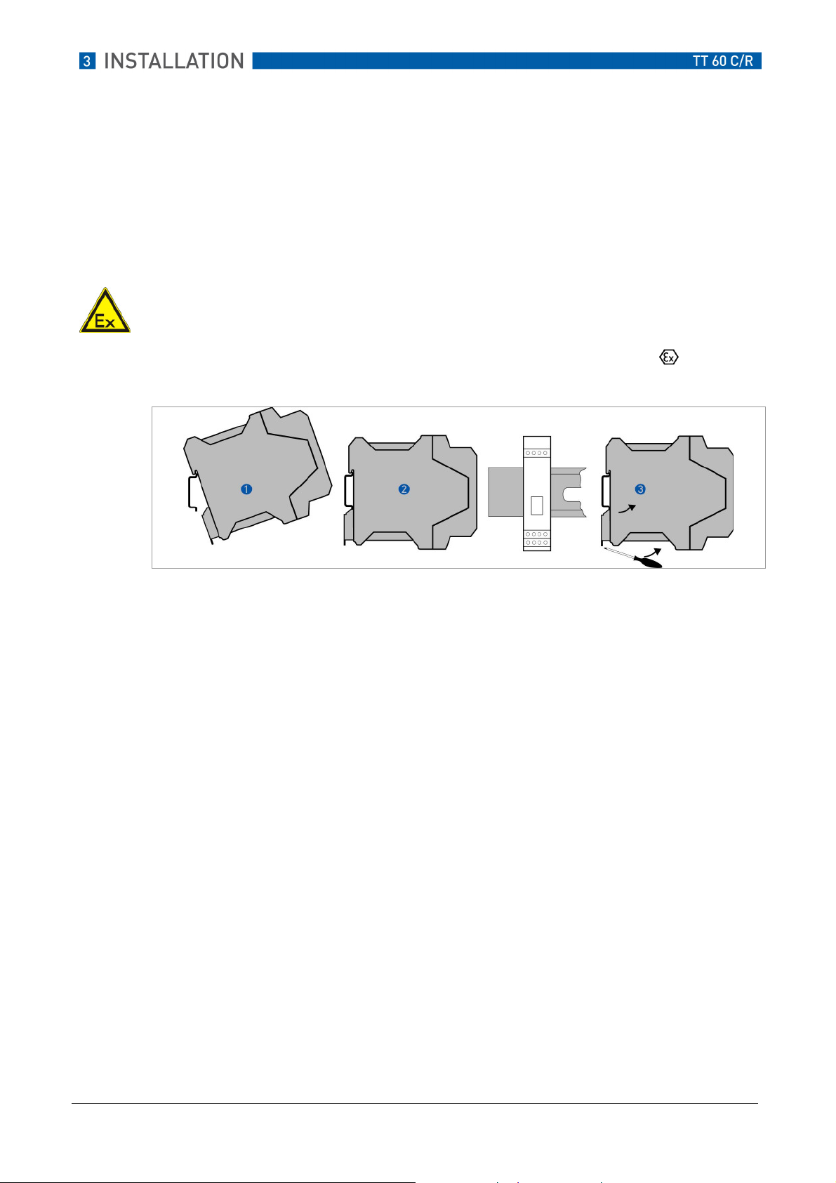
3.2 TT 60 R installation
The TT 60 R transmitter is intended for installation on a top-hat rail according to DIN EN 50022.
AT
ATTENTION!
TENTION!
ATAT
TENTION!TENTION!
The TT 60 R may not be installed for measurements in areas with potentially explosive
atmospheres.
For measurements in areas with potentially explosive atmospheres, the TT 60 C
used.
Figure 2: TT 60 R rail installation
1
Hook the upper groove of the transmitter onto the rail.
2
Press the transmitter downwards until the snap fastener engages on the rail.
To remove, press the snap fastener downwards using a screwdriver. Carefully pull the
3
transmitter forwards.
must be
11/2010 – 4000754401 – MA OPTITEMP TT60CR R01 en www.krohne.com
10
Page 11

4 Electrical connections
4.1 Safety instructions
ATTENTION!
ATTENTION!
ATTENTION!ATTENTION!
Only trained and qualified personnel may carry out any work on the device. Always observe the
regional industrial safety and other safety regulations.
ATTENTION!
ATTENTION!
ATTENTION!ATTENTION!
Any work on the electrical connections may only be carried out in the de-energized state.
Observe the voltage specifications on the rating plate!
Observe the national regulations for electrical installations!
The transmitter is protected against polarity reversal.
polarity of the supply voltage is switched.
ATTENTION!
ATTENTION!
ATTENTION!ATTENTION!
When connecting devices with an Ex certificate, observe the corresponding chapters and the
instructions in this manual.
No damage will occur to the device if the
The TT 60 C
equipment" in standard EN 50020:2002, section 5.4
may only be connected to sensors that meet the requirements for "simple
.
The transmitter must be supplied with power by an intrinsically safe power supply unit or Zener
barrier outside of the potentially explosive zone.
11/2010 – 4000754401 – MA OPTITEMP TT60CR R01 en www.krohne.com
11
Page 12

4.2 Connections
The input and output signals and the power supply must be connected in accordance with the
following illustrations. The in-head transmitter is easy to install with the KROHNE connection
head installation kit (see order information chapter 7.1). To avoid measuring errors, all cables
must be connected properly and the screws tightened correctly.
Figure 3: Installation diagram, TT 60 C/R
1
Pt100, Pt1000, Ni100, Ni1000, "SmartSense", 2-wire connection
2
Pt100, Pt1000, Ni100, Ni1000, "SmartSense", 3-wire connection
3
Pt100, Pt1000, Ni100, Ni1000, "SmartSense", 4-wire connection
4
Pt100, redundant sensor elements
5
Potentiometer, 2-wire connection
6
1) SmartSense wire
Potentiometer, 3-wire connection
11/2010 – 4000754401 – MA OPTITEMP TT60CR R01 en www.krohne.com
12
Page 13

Figure 4: Installation diagram, TT 60 C/R
1
Potentiometer, 4-wire connection
2
Thermocouple
3
Thermocouple, redundant sensor elements
4
Thermocouple, with remote reference junction compensation
5
Voltage
6
1) SmartSense wire
Voltage, redundant
4.3 ProfiBus connection
4.3.1 Shielding and grounding
In environments subject to electrical interference, shielded and twisted wires enable precise
measurement results.
The electrical wiring of the data bus must be installed properly and shielded in order to enable
precise measurement results.
IMPORTANT NOTE!
IMPORTANT NOTE!
IMPORTANT NOTE!IMPORTANT NOTE!
If you use non-shielded wires, they must not be laid near power cables or electrical loads.
In order to ensure the electromagnetic compatibility of the entire measuring system, all
components must be shielded and grounded.
The shields and grounds must provide complete protection against interference.
11/2010 – 4000754401 – MA OPTITEMP TT60CR R01 en www.krohne.com
13
Page 14

CAUTION!
CAUTION!
CAUTION!CAUTION!
EN 61158-2 stipulates that all data bus interfaces must be isolated from the local ground.
The ProfiBus must not be grounded.
Figure 5: Circuit schematic, ProfiBus shielding and grounding
1
Power supply
2
Supply cable
3
Connection box
4
Connection cable to field device
5
Field device
6
Equipotential bonding
4.3.2 Cable parameters for areas with potentially explosive atmospheres
Resistance Values
Cable resistance 15...150 Ω/km
Cable inductance 0.4...1 mH/km
Cable capacitance 45...200 nF/km
11/2010 – 4000754401 – MA OPTITEMP TT60CR R01 en www.krohne.com
14
Page 15

4.3.3 Terminator
The ProfiBus cable must be terminated at both ends.
The terminator consists of a capacitor and a film resistor connected in series.
Values
4.3.4 ProfiBus architecture
Figure 6: Typical ProfiBus architecture
ProfiBus DP components
1
DP/PA segment coupler with 3 and 4
2
Signal coupler
3
Power supply
4
Connection box
5
PA segment
6
Bus terminator
7
Field devices
8
The illustration above shows a typical ProfiBus architecture. Field devices with low power
consumption (e.g. pressure and temperature transmitters) are fed via the two-wire bus. Signal
transmission is likewise via the bus.
In the case of installations in areas without potentially explosive atmospheres, up to 32 devices
can be connected per segment, depending on the power rating of the segment coupler.
In the case of installations in areas with potentially explosive atmospheres, normally 10 devices
can be connected per segment.
(T)
R = 100 Ω ± 2%
C = 1 µF ± 20%
11/2010 – 4000754401 – MA OPTITEMP TT60CR R01 en www.krohne.com
15
Page 16

4.4 TT 60 C connection diagram
ATTENTION!
ATTENTION!
ATTENTION!ATTENTION!
The TT 60 C may only be operated in areas with potentially explosive atmospheres Zone 2 and in
safe areas.
Figure 7: TT 60 C connection diagram
1
Input
2
ProfiBus PA® terminator
3
ProfiBus PA® output, bus lines
Bus feed unit / segment coupler
4
(in the case of applications in areas with potentially explosive atmospheres, certified
devices must be used)
11/2010 – 4000754401 – MA OPTITEMP TT60CR R01 en www.krohne.com
16
Page 17

4.5 TT 60 C connection diagram
ATTENTION!
ATTENTION!
ATTENTION!ATTENTION!
The transmitter may be operated in areas with potentially explosive atmospheres if the voltage
supply is ensured by means of an appropriate power supply unit or a Zener barrier!
Figure 8: TT 60 C connection diagram
1
Input
2
ProfiBus PA® terminator
3
ProfiBus PA® output, bus lines
4
Certified bus feed unit / segment coupler
5
Safe area
6
Area with potentially explosive atmosphere
11/2010 – 4000754401 – MA OPTITEMP TT60CR R01 en www.krohne.com
17
Page 18

4.6 TT 60 R connection diagram
ATTENTION!
ATTENTION!
ATTENTION!ATTENTION!
Neither install the transmitter in an area with a potentially explosive atmosphere, nor connect it
to a sensor in an area with a potentially explosive atmosphere!
1
Input
2
ProfiBus PA® terminator
3
ProfiBus PA® output, bus lines
Bus feed unit / segment
4
coupler
Figure 9: TT 60 R connection diagram
11/2010 – 4000754401 – MA OPTITEMP TT60CR R01 en www.krohne.com
18
Page 19

5 Operation
5.1 Connection using the KROHNE PC configuration set
ATTENTION!
ATTENTION!
ATTENTION!ATTENTION!
No PC may be connected to a transmitter in areas with potentially explosive atmospheres.
If you wish to configure the transmitter with the PC, this must be done outside of the area with a
potentially explosive atmosphere or by means of communication via ProfiBus.
If the transmitter is configured with the PC, a configuration cable and an adapter from the
configuration set (order number see Chapter 7.1) must be used as the connection between the
PC and the transmitter.
An ATEX certified cable must be used for transmitters bearing the symbol.
TT 60 C X X
TT 60 C
TT 60 R X X
Type A Type C
X X
Table 1: PC connection cable
Type A
Cable
Type C
Adapter
Figure 10: PC connection cable
Order number Comment
Type A (cable) VI70IPRX0002 ATEX certified
Type C (adapter) VI70IPRP0001 --
11/2010 – 4000754401 – MA OPTITEMP TT60CR R01 en www.krohne.com
19
Page 20

5.2 General
IMPORTANT NOTE
IMPORTANT NOTE!
IMPORTANT NOTEIMPORTANT NOTE
The TT 60 is shipped ex works with a standard configuration.
Standard settings:
Standard settings:
Standard settings:Standard settings:
Address 126
Input signal Pt100, 4-wire
Output signal °C
Filter 0 s
Sensor monitoring Off
All models of the TT 60 series have a ProfiBus PA®-interface. The transmitters can be
configured using
With a PC, configuration can be carried out before the device is integrated into the ProfiBus.
Configuration using a PC requires a connection to a serial interface and the "ProfiSoft"
software.
The current version of the software is available for download on our website
http://www.krohne.com/html/dlc/index.shtml.
You can find configuration instructions in the "ProfiSoft" reference manual.
o ProfiBus PA®o an IBM compatible PC.
11/2010 – 4000754401 – MA OPTITEMP TT60CR R01 en www.krohne.com
20
Page 21

5.2.1 Smart Sense
If the appropriate measuring sensors are provided (an additional wire in the sensor), the
transmitter can continuously monitor the insulation resistance of the sensor, including the
connection wires. This function (Smart Sense) is possible for resistance thermometers and
thermocouples. If the insulation resistance is too low, the measured result will be incorrect and
a message will be generated via ProfiBus.
This function requires configuration with the "ProfiSoft" software via a PC or via the ProfiBus.
5.2.2 Monitoring of sensor aging
If a resistance thermometer or a thermocouple with two sensors is used, the TT 60 can be used
to monitor the aging of the sensor. The transmitter compares the measured values of the two
sensors. Aging is indicated if the differential between the measured values is too great. In this
case a message is generated via the ProfiBus. For further information, see the "Profisoft"
manual.
Action
Action
ActionAction
To protect the PC connections, they must be closed off using the supplied protection caps
after configuration has been completed.
11/2010 – 4000754401 – MA OPTITEMP TT60CR R01 en www.krohne.com
21
Page 22

6 Technical data
6.1 TT 60 C specifications
6.1.1 Technical data
Designation
Input
Input Pt10, Pt50, Pt100, Pt200,
InputInput
Ni50, Ni100, Ni120, Ni1000 -200... +250°C
Designation Value
DesignationDesignation
Value
ValueValue
-200...+850°C
Pt500, Pt1000
Potentiometer
0...4000 Ω
Thermocouples Types: B, C, D, E, G, J, K, L, N, R, S,
T, U
Voltage -10...+1000 mV
Redundan
Redundant channels and
RedundanRedundan
arithmetic functions
arithmetic functions
arithmetic functionsarithmetic functions
t channels and
t channels and t channels and
Differential channel 1 - channel 2 or
channel 2 - channel 1
Average value 0.5 x (channel 1 + channel 2)
Average value with
redundancy
0.5 x (channel 1 + channel 2),
channel 1 or channel 2 if the other
channel fails
Minimum value Min (channel 1, channel 2)
Maximum value Max (channel 1, channel 2)
Sensor break function
Sensor break function On / Off
Sensor break functionSensor break function
Output
Output ProfiBus-PA ®
OutputOutput
Ambient temperat
Ambient temperature
Ambient temperatAmbient temperat
Galvanic isolation
Galvanic isolation 1500 VAC, 1 min
Galvanic isolationGalvanic isolation
Power supply
Power supply
Power supplyPower supply
Power consumption
Power consumption 11 mA
Power consumptionPower consumption
ure -40...+85°C
ureure
9...32 VDC
Typical accuracy
Typical accuracy Pt100 0.1°C
Typical accuracyTypical accuracy
Connection head
Connection head DIN B or larger
Connection headConnection head
Table 2: TT 60 C specifications
11/2010 – 4000754401 – MA OPTITEMP TT60CR R01 en www.krohne.com
22
Page 23

6.1.2 TT 60 C dimensions
Dimension [mm] Dimension [inch]
1
2
3
4
44 1.73
27 1.06
7 0.28
33 1.30
Figure 11: TT 60 C dimensions
6.1.3 Data inputs and outputs
Bus connection
Bus connection
Bus connection Bus connection
(terminals 6+7)
(terminals 6+7)
(terminals 6+7)(terminals 6+7)
Ui:= V
Ii: = I
Pi: = P
30 VDC U0 = Voc 30 VDC Ui: = V
max
not limited I0 = Isc 0.4 mA Ii: = I
max
not limited P0 = Pt 6.5 mW Pi: = P
max
Sensor connection
Sensor connection
Sensor connectionSensor connection
(terminals 1
(terminals 1----5)
(terminals 1(terminals 1
5)
5)5)
Communic
Communications connection
CommunicCommunic
ations connection
ations connectionations connection
8.0 VDC
max
450 mA
max
800 mW
max
Ci: 1 nF C0 = Ca 1000 nF Ci: 10 nF
Li 10 µH L0 = La 750 mH Li 1 µH
Table 3: TT 60 C input/output electrical data
6.1.4 Ambient temperature data for areas with potentially explosive atmospheres, TT 60 C
Temperature class
Temperature class Ambient temperature
Temperature classTemperature class
Ambient temperature
Ambient temperatureAmbient temperature
T6
T5
T4
Tabelle 4: Temperature data, TT 60 C
-40°C ≤ Ta ≤ +75°C
-40°C ≤ Ta ≤ +85°C
-40°C ≤ Ta ≤ +85°C
11/2010 – 4000754401 – MA OPTITEMP TT60CR R01 en www.krohne.com
23
Page 24

6.2 TT 60 C specifications
6.2.1 Technical data
Designation
Input
Input Pt10, Pt50, Pt100, Pt200,
InputInput
Ni50, Ni100, Ni120, Ni1000 -200...+250°C
Designation Value
DesignationDesignation
Value
ValueValue
-200...+850°C
Pt500, Pt1000
Potentiometer
0...4000 Ω
Thermocouples Types: B, C, D, E, G, J, K, L, N, R, S,
T, U
Voltage -10...+1000 mV
Redundant channels and
Redundant channels and
Redundant channels and Redundant channels and
arithmetic functions
arithmetic functions
arithmetic functionsarithmetic functions
Differential channel 1 - channel 2 or
channel 2 - channel 1
Average value 0.5 x (channel 1 + channel 2)
Average value with
redundancy
0.5 x (channel 1 + channel 2),
channel 1 or channel 2 if the other
channel fails
Minimum value Min (channel 1, channel 2)
Maximum value Max (channel 1, channel 2)
Sensor break function
Sensor break function On / Off
Sensor break functionSensor break function
Output
Output ProfiBus-PA ®
OutputOutput
Ambi
Ambient temperature
ent temperature -40...+85°C
AmbiAmbi
ent temperatureent temperature
Galvanic isolation
Galvanic isolation 1500 VAC, 1 min
Galvanic isolationGalvanic isolation
Power supply
Power supply
Power supplyPower supply
Power consumption
Power consumption 11 mA
Power consumptionPower consumption
9...17.5 VDC
Typical accuracy
Typical accuracy Pt100 0.1°C
Typical accuracyTypical accuracy
Connection head
Connection head DIN B or larger
Connection headConnection head
Table 5: TT 60 C specifications
11/2010 – 4000754401 – MA OPTITEMP TT60CR R01 en www.krohne.com
24
Page 25

6.2.2 TT 60 C dimensions
Dimension [mm]
1
2
3
4
Dimension [mm] Dimension [inch]
Dimension [mm]Dimension [mm]
Dimension [inch]
Dimension [inch]Dimension [inch]
44 1.73
27 1.06
7 0.28
33 1.06
Figure 12: TT 60 C dimensions
6.2.3 Data inputs and outputs
Bus connection
Bus connection
Bus connection Bus connection
(terminals 6+7)
(terminals 6+7)
(terminals 6+7)(terminals 6+7)
Ui:= V
Ii: = I
Pi: = P
17.5 VDC U0 = Voc 17.5 VDC Ui: = V
max
380 mA I0 = Isc 56 mA Ii: = I
max
5.32 W P0 = Pt 244 mW Pi: = P
max
Sensor connection
Sensor connection
Sensor connectionSensor connection
(term
(terminals 1
(term(term
inals 1----5)
inals 1inals 1
5)
5)5)
Communications connection
Communications connection
Communications connectionCommunications connection
8.0 VDC
max
450 mA
max
800 mW
max
Ci: 1 nF C0 = Ca 166 nF Ci: 10 nF
Li 10 µH L0 = La 6 mH Li 1 µH
Table 6: TT 60 C input/output electrical data
6.2.4 Ambient temperature data for areas with potentially explosive atmospheres, TT 60 C
Temperature class
Temperature class Ambient temperature
Temperature classTemperature class
Ambient temperature
Ambient temperatureAmbient temperature
T6
T5
T4
Table 7: TT 60 C temperature data
-40°C ≤ Ta ≤ +45°C
-40°C ≤ Ta ≤ +60°C
-40°C ≤ Ta ≤ +85°C
11/2010 – 4000754401 – MA OPTITEMP TT60CR R01 en www.krohne.com
25
Page 26

6.3 TT 60 R specifications
6.3.1 Technical data
Designation
Input
Input Pt10, Pt50, Pt100, Pt200,
InputInput
Ni50, Ni100, Ni120, Ni1000 -200...+250°C
Designation Value
DesignationDesignation
Value
ValueValue
-200...+850°C
Pt500, Pt1000
Potentiometer
0...4000 Ω
Thermocouples Types: B, C, D, E, G, J, K, L, N, R, S,
T, U
Voltage -10...+1000 mV
Redundant channels and
Redundant channels and
Redundant channels and Redundant channels and
arithmetic functions
arithmetic functions
arithmetic functionsarithmetic functions
Differential channel 1 - channel 2 or
channel 2 - channel 1
Average value 0.5 x (channel 1 + channel 2)
Average value with
redundancy
0.5 x (channel 1 + channel 2),
channel 1 or channel 2 if the other
channel fails
Minimum value Min (channel 1, channel 2)
Maximum value Max (channel 1, channel 2)
Sensor break function
Sensor break function On / Off
Sensor break functionSensor break function
Output
Output ProfiBus-PA ®
OutputOutput
Ambient temperature
Ambient temperature -20.. +70°C
Ambient temperatureAmbient temperature
Galvanic isolation
Galvanic isolation 1500 VAC, 1 min
Galvanic isolationGalvanic isolation
Power supply
Power supply
Power supplyPower supply
Power consumption
Power consumption 11 mA
Power consumptionPower consumption
9...32 VDC
Typical accuracy
Typical accuracy Pt100 0.1°C
Typical accuracyTypical accuracy
Installation
Installation Rail according to EN 50020, 35 mm
InstallationInstallation
Table 8: TT 60 R specifications
11/2010 – 4000754401 – MA OPTITEMP TT60CR R01 en www.krohne.com
26
Page 27

6.3.2 TT 60 R dimensions
Figure 13: TT 60 R dimensions
Dimension [mm]
Dimension [mm]
Dimension [mm]Dimension [mm]
1
2
3
115 4.53
100 3.93
22.5 0.88
Dimension [inch]
Dimension [inch]
Dimension [inch]Dimension [inch]
11/2010 – 4000754401 – MA OPTITEMP TT60CR R01 en www.krohne.com
27
Page 28

7 Service
7.1 Ordering information
Product
Product Order No.
ProductProduct
TT 60 C VIP04H000010000
Order No.
Order No.Order No.
TT 60 C ATEX
VIP04HX00010000
TT 60 R VIP04L000010000
Software and cables
Software and cables
Software and cablesSoftware and cables
PC configuration set VI70CFG00092
ATEX cable for PC connection
VI70IPRX0002
(contained in the configuration set VI70CFG00092)
Adapter cable (4-pole)
VI70IPRP0001
(contained in the configuration set VI70CFG00092)
Accessories
Accessories
AccessoriesAccessories
Field housing for floor installation VI70ADA00008
Field housing for DIN rail installation VI70ADA00009
Connection head installation kit VI70ADA00017
Rail installation clip VI70ADA00013
Display LCD-W12 VI70LCDW1201
Configuration ex works VI70CAL00001
11/2010 – 4000754401 – MA OPTITEMP TT60CR R01 en www.krohne.com
28
Page 29

For your notes:
11/2010 – 4000754401 – MA OPTITEMP TT60CR R01 en www.krohne.com
29
Page 30

For your notes:
11/2010 – 4000754401 – MA OPTITEMP TT60CR R01 en www.krohne.com
30
Page 31

For your notes:
11/2010 – 4000754401 – MA OPTITEMP TT60CR R01 en www.krohne.com
31
Page 32

 Loading...