

Page 1

Handbook
Handbook
OPTITEMP TT 50 C/R
OPTITEMP TT 50 C/R
OPTITEMP TT 50 C/ROPTITEMP TT 50 C/R
HART®-compatible, intelligent two-wire transmitter
HandbookHandbook
© KROHNE 09/2010 - 4000636502 - MA OPTITEMP TT 50 C/R R03 en
Page 2

: IMPRINT ::::::::::::::::::::::::::::::::::
OPTITEMP TT 50 C/R
All rights reserved. It is prohibited to reproduce this documentation, or any part thereof, without
the prior written authorisation of KROHNE Messtechnik GmbH.
Subject to change without notice.
Copyright 2010 by
KROHNE Messtechnik GmbH - Ludwig-Krohne-Str. 5 - 47058 Duisburg (Germany)
2
www.krohne.com 09/2010 - 4000636502 - MA OPTITEMP TT 50 C/R R03 en
Page 3

OPTITEMP TT 50 C/R
CONTENTS
1 Safety instructions 5
1.1 Intended use ..................................................................................................................... 5
1.2 Certifications .................................................................................................................... 5
1.2.1 EC directive compliance ......................................................................................................... 5
1.2.2 Ex approvals (TT 50 C Ex)........................................................................................................ 5
1.3 Safety instructions from the manufacturer ..................................................................... 6
1.3.1 Copyright and data protection ................................................................................................ 6
1.3.2 Disclaimer ............................................................................................................................... 6
1.3.3 Product liability and warranty ................................................................................................ 7
1.3.4 Information concerning the documentation........................................................................... 7
1.3.5 Warnings and symbols used................................................................................................... 8
1.4 Safety instructions for the operator................................................................................. 8
2 Device description 9
2.1 Scope of delivery............................................................................................................... 9
2.2 General description .......................................................................................................... 9
2.3 Nameplate ...................................................................................................................... 10
2.3.1 Example of a nameplate for an in-head transmitter (Non-Ex)............................................ 10
2.3.2 Example of namplates for an in-head transmitter (Ex) ....................................................... 10
2.3.3 Nameplate for rail-mount transmitter................................................................................. 11
3 Installation 12
3.1 Notes on installation ......................................................................................................12
3.2 In-head transmitter........................................................................................................12
3.3 Rail-mount transmitter .................................................................................................. 14
4 Electrical connections 15
4.1 Safety instructions.......................................................................................................... 15
4.2 Electrical connections (in-head and rail-mount)........................................................... 15
4.3 Connection diagram of in-head transmitter.................................................................. 17
4.4 Connection diagram of in-head transmitter (Ex)........................................................... 18
4.5 Connection diagram of rail-mount transmitter............................................................. 19
4.6 Cable length.................................................................................................................... 19
5 Operation 21
5.1 HART® networks ............................................................................................................ 21
5.1.1 Point-to-point connection analog / digital mode ................................................................. 21
5.1.2 Multi-drop connection (2-wire connection).......................................................................... 22
5.2 Factory settings for configuration.................................................................................. 23
5.3 Configuration of transmitter .......................................................................................... 24
5.3.1 Configuration with PC and HART®-modem ......................................................................... 24
5.3.2 Configuration with a hand held communicator FC375/FC475............................................. 24
5.3.3 Device management software .............................................................................................. 25
5.4 Factory calibration of transmitter.................................................................................. 25
www.krohne.com09/2010 - 4000636502 - MA OPTITEMP TT 50 C/R R03 en
3
Page 4

CONTENTS
OPTITEMP TT 50 C/R
6 Service 26
6.1 Spare parts availability...................................................................................................26
6.2 Availability of services .................................................................................................... 26
6.3 Returning the device to the manufacturer..................................................................... 26
6.3.1 General information.............................................................................................................. 26
6.3.2 Form (for copying) to accompany a returned device............................................................ 27
6.4 Disposal .......................................................................................................................... 27
7 Technical data 28
7.1 Measuring principles...................................................................................................... 28
7.1.1 Resistance thermometer...................................................................................................... 28
7.1.2 Thermocouples ..................................................................................................................... 29
7.2 Technical data................................................................................................................. 30
7.3 Dimensions ..................................................................................................................... 34
7.4 Output load diagrams..................................................................................................... 36
7.5 Temperature data for potentially explosive areas......................................................... 37
7.6 Electrical data for outputs and inputs............................................................................ 37
7.7 RTD and T/C accuracy table ........................................................................................... 38
8 Notes 39
4
www.krohne.com 09/2010 - 4000636502 - MA OPTITEMP TT 50 C/R R03 en
Page 5

OPTITEMP TT 50 C/R
1.1 Intended use
TT 50 C
The TT 50 C is an intelligent, universal HART®-compatible 2-wire in-head transmitter for
temperature, resistance or voltage measurements in an industrial environment.
The transmitter is optionally available in an intrinsically safe version for installation in
potentially explosive areas. These devices are labeled with the "Ex" symbol (TT 50 C Ex) and are
approved for use in zone 0, 1 and 2 and division 1 and 2.
All versions are intended for installation in a "B connection head" or larger according to
DIN 43729.
TT 50 R
The TT 50 R is an intelligent, universal HART®-compatible 2-wire rail-mount transmitter for
temperature, resistance or voltage measurements in an industrial environment.
All versions are intended for installation on a top-hat rail according to DIN 50022.
SAFETY INSTRUCTIONS 1
1.2 Certifications
1.2.1 EC directive compliance
CE marking
The device fulfils all applicable statutory requirements of the following EC directives:
• EMC Directive 2004/108/EC
• Devices for use in potentially explosive areas: ATEX Directive 94/9/EC
The manufacturer certifies successful testing of the product by applying the CE marking.
1.2.2 Ex approvals (TT 50 C Ex)
ATEX II 1 G Ex ia IIC T4/T5/T6
T4: +85°C / +185°F, T5: +65°C / +149°F, T6: +50°C / +122°F
DEMKO 06 ATEX 141335X
INFORMATION!
See also "Certificates" in the download area of the manufacturer's website.
www.krohne.com09/2010 - 4000636502 - MA OPTITEMP TT 50 C/R R03 en
5
Page 6

1 SAFETY INSTRUCTIONS
1.3 Safety instructions from the manufacturer
1.3.1 Copyright and data protection
The contents of this document have been created with great care. Nevertheless, we provide no
guarantee that the contents are correct, complete or up-to-date.
The contents and works in this document are subject to copyright. Contributions from third
parties are identified as such. Reproduction, processing, dissemination and any type of use
beyond what is permitted under copyright requires written authorisation from the respective
author and/or the manufacturer.
The manufacturer tries always to observe the copyrights of others, and to draw on works created
in-house or works in the public domain.
The collection of personal data (such as names, street addresses or e-mail addresses) in the
manufacturer's documents is always on a voluntary basis whenever possible. Whenever
feasible, it is always possible to make use of the offerings and services without providing any
personal data.
OPTITEMP TT 50 C/R
We draw your attention to the fact that data transmission over the Internet (e.g. when
communicating by e-mail) may involve gaps in security. It is not possible to protect such data
completely against access by third parties.
We hereby expressly prohibit the use of the contact data published as part of our duty to publish
an imprint for the purpose of sending us any advertising or informational materials that we have
not expressly requested.
1.3.2 Disclaimer
The manufacturer will not be liable for any damage of any kind by using its product, including,
but not limited to direct, indirect, incidental, punitive and consequential damages.
This disclaimer does not apply in case the manufacturer has acted on purpose or with gross
negligence. In the event any applicable law does not allow such limitations on implied warranties
or the exclusion of limitation of certain damages, you may, if such law applies to you, not be
subject to some or all of the above disclaimer, exclusions or limitations.
Any product purchased from the manufacturer is warranted in accordance with the relevant
product documentation and our Terms and Conditions of Sale.
The manufacturer reserves the right to alter the content of its documents, including this
disclaimer in any way, at any time, for any reason, without prior notification, and will not be liable
in any way for possible consequences of such changes.
6
www.krohne.com 09/2010 - 4000636502 - MA OPTITEMP TT 50 C/R R03 en
Page 7

OPTITEMP TT 50 C/R
1.3.3 Product liability and warranty
The operator shall bear responsibility for the suitability of the device for the specific purpose.
The manufacturer accepts no liability for the consequences of misuse by the operator. Improper
installation and operation of the devices (systems) will cause the warranty to be void. The
respective "Standard Terms and Conditions" which form the basis for the sales contract shall
also apply.
1.3.4 Information concerning the documentation
To prevent any injury to the user or damage to the device it is essential that you read the
information in this document and observe applicable national standards, safety requirements
and accident prevention regulations.
If this document is not in your native language and if you have any problems understanding the
text, we advise you to contact your local office for assistance. The manufacturer can not accept
responsibility for any damage or injury caused by misunderstanding of the information in this
document.
This document is provided to help you establish operating conditions, which will permit safe and
efficient use of this device. Special considerations and precautions are also described in the
document, which appear in the form of underneath icons.
SAFETY INSTRUCTIONS 1
www.krohne.com09/2010 - 4000636502 - MA OPTITEMP TT 50 C/R R03 en
7
Page 8
1 SAFETY INSTRUCTIONS
1.3.5 Warnings and symbols used
Safety warnings are indicated by the following symbols.
DANGER!
This information refers to the immediate danger when working with electricity.
DANGER!
This warning refers to the immediate danger of burns caused by heat or hot surfaces.
DANGER!
This warning refers to the immediate danger when using this device in a hazardous atmosphere.
DANGER!
These warnings must be observed without fail. Even partial disregard of this warning can lead to
serious health problems and even death. There is also the risk of seriously damaging the device
or parts of the operator's plant.
OPTITEMP TT 50 C/R
WARNING!
Disregarding this safety warning, even if only in part, poses the risk of serious health problems.
There is also the risk of damaging the device or parts of the operator's plant.
CAUTION!
Disregarding these instructions can result in damage to the device or to parts of the operator's
plant.
INFORMATION!
These instructions contain important information for the handling of the device.
LEGAL NOTICE!
This note contains information on statutory directives and standards.
• HANDLING
HANDLING
HANDLINGHANDLING
This symbol designates all instructions for actions to be carried out by the operator in the
specified sequence.
i RESULT
RESULT
RESULTRESULT
This symbol refers to all important consequences of the previous actions.
1.4 Safety instructions for the operator
WARNING!
In general, devices from the manufacturer may only be installed, commissioned, operated and
maintained by properly trained and authorized personnel.
This document is provided to help you establish operating conditions, which will permit safe and
efficient use of this device.
8
www.krohne.com 09/2010 - 4000636502 - MA OPTITEMP TT 50 C/R R03 en
Page 9

OPTITEMP TT 50 C/R
2.1 Scope of delivery
The scope of delivery always consists of the transmitter and its documentation.
2.2 General description
The TT 50 transmitters are intelligent 2-wire universal transmitters with one channel.
The transmitters are intended for:
• Temperature measurements with resistance thermometers
• Temperature measurements with thermocouples
• Temperature difference measurements with resistance thermometers
• Measurements with potentiometers
• Voltage measurements in a range -10…+500 mV
INFORMATION!
The TT 50 C
TT 50 C is optionally available for operation in potentially explosive areas (zone 0, 1 and 2
TT 50 CTT 50 C
and division 1 and 2).
DEVICE DESCRIPTION 2
The TT 50 C / TT 50 C Ex
TT 50 C / TT 50 C Ex are designed for installation in a "B connection head" according to
TT 50 C / TT 50 C ExTT 50 C / TT 50 C Ex
DIN 43729 or larger.
The TT 50 R
TT 50 R is designed for installation on a rail according to DIN 50022.
TT 50 RTT 50 R
®
The 2-wire universal transmitters are HART
possible with:
®
• HART
• HART
• The third part PC software with a FSK modem for HART
• PC configuration software (HartSoft) with HART
To configure the transmitter using an IBM-compatible PC, the "HartSoft" software is required.
The Windows-based "HartSoft" software can be used to access all functions of the transmitter. It
is also used for configuration, calibration, display and documentation.
5 protocol via 4…20 mA output circuit
®
5 hand held terminal
5-compatible. Configuration of the transmitter is
®
5 communication
®
modem
www.krohne.com09/2010 - 4000636502 - MA OPTITEMP TT 50 C/R R03 en
9
Page 10
2 DEVICE DESCRIPTION
2.3 Nameplate
INFORMATION!
Look at the device nameplate to ensure that the device is delivered according to your order.
Check for the correct supply voltage printed on the nameplate.
The transmitter can be identified by the information on the nameplates.
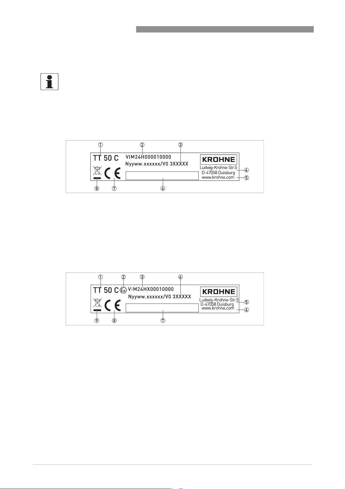
2.3.1 Example of a nameplate for an in-head transmitter (Non-Ex)
1 Product name
2 Part number
3 Year and week of manufacturing / batch number
4 Manufacturer and address
5 Website of manufacturer
6 Space for configuration data sticker
7 CE marking (EC conformity)
8 WEEE dustbin symbol
OPTITEMP TT 50 C/R
2.3.2 Example of namplates for an in-head transmitter (Ex)
1 Product name
2 Symbol for Ex-approval
3 Part number
4 Year and week of manufacturing / batch number
5 Manufacturer and address
6 Website of manufacturer
7 Space for configuration data sticker
8 CE marking (EC conformity)
9 WEEE dustbin symbol
10
www.krohne.com 09/2010 - 4000636502 - MA OPTITEMP TT 50 C/R R03 en
Page 11
OPTITEMP TT 50 C/R
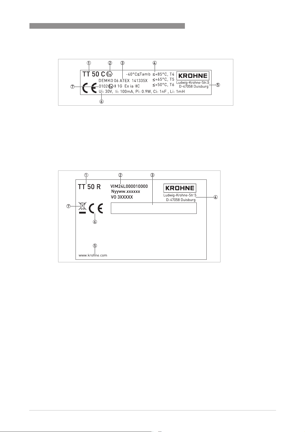
1 Product name
2 Symbol for Ex-approval
3 ATEX approval
4 Temperature classes
5 Manufacturer and address
6 Ex-relevant electrical data
7 Supplementary Ex-data
2.3.3 Nameplate for rail-mount transmitter
DEVICE DESCRIPTION 2
1 Product name
2 Top down: part number, year and week of manufacturing, batch number
3 Space for configuration data sticker
4 Manufacturer and address
5 Website of manufacturer
6 CE marking (EC conformity)
7 WEEE dustbin symbol
www.krohne.com09/2010 - 4000636502 - MA OPTITEMP TT 50 C/R R03 en
11
Page 12
3 INSTALLATION
3.1 Notes on installation
INFORMATION!
Inspect the cartons carefully for damage or signs of rough handling. Report damage to the
carrier and to the local office of the manufacturer.
INFORMATION!
Check the packing list to check if you received completely all that you ordered.
INFORMATION!
Look at the device nameplate to ensure that the device is delivered according to your order.
Check for the correct supply voltage printed on the nameplate.
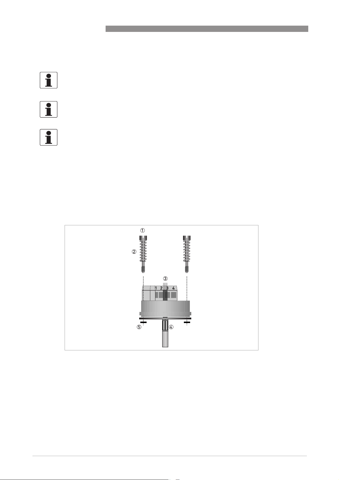
3.2 In-head transmitter
These transmitters are intended for installation in DIN B connection heads or larger. The large
Ø7 mm / 0.28" center hole facilitates the electrical connection of the measurement sensor and
the installation. For detailed information refer to the chapter "Dimensions and weights".
OPTITEMP TT 50 C/R
12
1 Screw M4
2 Spring
3 Sensor connection cables
4 Protection tube
5 Lock washer
www.krohne.com 09/2010 - 4000636502 - MA OPTITEMP TT 50 C/R R03 en
Page 13

OPTITEMP TT 50 C/R
DANGER!
Never install or operate the TT 50 C in potentially explosive areas, it might cause an explosion
that can result in fatal injuries! Only use the TT 50 C Ex in potentially explosive areas!
The Ex transmitter can be installed in potentially hazardous areas zone 0, 1 and 2. It must be
supplied by an intrinsically safe power supply unit or Zener barrier placed outside of the
potentially explosive zone.
The Ex transmitter must be installed in a housing with the protection rating IP20 or better
according to EN 60529 / IEC 60529.
CAUTION!
The TT 50 C / TT 50 C Ex temperature transmitter has been developed for an ambient
temperature of -40...+85
dependent on the temperature category. For detailed information refer to Ex data of the ambient
temperature.
The process temperature is also transferred to the transmitter housing via the protective tube. If
the process temperature is close to or exceeds the maximum specified ambient temperature of
the transmitter, then the temperature in the transmitter housing can rise above the maximum
permissible ambient temperature. Always check that the ambient temperature does not exceed
the permissible range!
One way to decrease heat transfer via the protective tube is to make the protective tube longer or
in general to install the transmitter farther away from the heat source. The same safety
measures can be taken if the temperature is below the specified minimum temperature.
INSTALLATION 3
°
C / -40...+185°F. Please also note that the ambient temperature is also
CAUTION!
The TT 50 C Ex may only be installed in a light metal housing, whose magnesium component
does not exceed 6%.
www.krohne.com09/2010 - 4000636502 - MA OPTITEMP TT 50 C/R R03 en
13
Page 14

3 INSTALLATION
3.3 Rail-mount transmitter
DANGER!
Never install or operate the TT 50 C in potentially explosive areas, it might cause an explosion
that can result in fatal injuries!
The rail-mount transmitter is intended for installation on a rail according to DIN 50022.
OPTITEMP TT 50 C/R
1 Hook the upper groove of the transmitter onto the rail.
2 Press the lower part of the transmitter against the rail.
i When you hear a "click" from the snap fastener, the transmitter is fixed onto the rail
(drawing in the centre).
3 To remove the transmitter, use a small screwdriver to push the snap fastener downwards.
4 Carefully move the lower part of the transmitter in the forward direction and then upwards.
14
www.krohne.com 09/2010 - 4000636502 - MA OPTITEMP TT 50 C/R R03 en
Page 15

OPTITEMP TT 50 C/R
4.1 Safety instructions
DANGER!
All work on the electrical connections may only be carried out with the power disconnected. Take
note of the voltage data on the nameplate!
DANGER!
Observe the national regulations for electrical installations!
DANGER!
The transmitter is protected against polarity reversal. No damage will occur to the device if the
polarity of the supply voltage is switched. The output will then indicate 0 mA.
DANGER!
Always observe the corresponding chapters and the instructions in this manual when connecting
devices with an Ex certificate!
Never install or operate the TT 50 C in potentially explosive areas, it might cause an explosion
that can result in fatal injuries!
For the operation in potentially explosive areas the manufacturer offers the TT 50 C Ex. You may
only connect this transmitter to sensors that meet the requirements for "simple equipment" in
EN 60079-11:2007, section 5.7.
ELECTRICAL CONNECTIONS 4
WARNING!
Observe without fail the local occupational health and safety regulations. Any work done on the
electrical components of the measuring device may only be carried out by properly trained
specialists.
INFORMATION!
Look at the device nameplate to ensure that the device is delivered according to your order.
Check for the correct supply voltage printed on the nameplate.
4.2 Electrical connections (in-head and rail-mount)
The input and output signals and the power supply must be connected in accordance with the
following illustrations. The in-head transmitter is easy to install with the connection head
installation kit. To avoid measuring errors, all cables must be connected properly and the
screws tightened correctly.
www.krohne.com09/2010 - 4000636502 - MA OPTITEMP TT 50 C/R R03 en
15
Page 16

4 ELECTRICAL CONNECTIONS
Pt10...1000, Ni100, Ni1000, 4-wire connection
Pt10...1000, Ni100, Ni1000, 4-wire connection Pt10...1000, Ni100, Ni1000, 3-wire connection
Pt10...1000, Ni100, Ni1000, 4-wire connectionPt10...1000, Ni100, Ni1000, 4-wire connection
Pt100 "SmartSense", 3-wire connection
Pt100 "SmartSense", 3-wire connection Pt100, temperature difference, T
Pt100 "SmartSense", 3-wire connectionPt100 "SmartSense", 3-wire connection
Potentiometer, 4-wire connection
Potentiometer, 4-wire connection Potentiometer, 3-wire connection
Potentiometer, 4-wire connectionPotentiometer, 4-wire connection
OPTITEMP TT 50 C/R
Pt10...1000, Ni100, Ni1000, 3-wire connection
Pt10...1000, Ni100, Ni1000, 3-wire connectionPt10...1000, Ni100, Ni1000, 3-wire connection
Pt100, temperature difference, T
Pt100, temperature difference, TPt100, temperature difference, T
Potentiometer, 3-wire connection
Potentiometer, 3-wire connectionPotentiometer, 3-wire connection
1111>T2
Thermocouple
Thermocouple Voltage
ThermocoupleThermocouple
Voltage
VoltageVoltage
1 SmartSense wire
2 Maximum input
16
www.krohne.com 09/2010 - 4000636502 - MA OPTITEMP TT 50 C/R R03 en
Page 17

OPTITEMP TT 50 C/R
ELECTRICAL CONNECTIONS 4
4.3 Connection diagram of in-head transmitter
DANGER!
Never install or operate this transmitter in potentially explosive areas, it might cause an
explosion that can result in fatal injuries!
DANGER!
®
To enable HART
communication, the output circuit must have an output load of at least 250 Ω.
1 Input
2 SmartSense temperature sensor
3 Pt100 3-wire connection
4 Thermocouple
5 Output
6 Modem
7 Voltage supply 10…42 VDC
INFORMATION!
®
The HART
modem is connected parallel to the output load or parallel to the output of the
transmitter.
www.krohne.com09/2010 - 4000636502 - MA OPTITEMP TT 50 C/R R03 en
17
Page 18

4 ELECTRICAL CONNECTIONS
4.4 Connection diagram of in-head transmitter (Ex)
DANGER!
The Ex transmitter can be installed in potentially explosive areas of zone 0, 1 and 2. It may only
be connected to sensors that meet the requirements for "simple equipment" in EN 6007911:2007, section 5.7. During operations in potentially explosive areas always regard the relevant
safety instructions and especially the following items:
•
The transmitter must be supplied by an intrinsically safe power supply unit or Zener barrier
placed outside of the potentially explosive area.
•
The output parameters of the Ex approved Zener barrier or voltage supply and the output
parameters of the Ex approved HART unit or modem have to be less or equal than the input
parameters of the transmitter (i.e. U
•
Only use an Ex approved HART® modem.
•
Observe the maximum cable lenght of the output circuit to ensure reliable HART®
communication with this transmitter ( on page 19
DANGER!
®
To enable HART
communication, the output circuit must have an output load of at least 250 Ω.
, Ii, Pi, Li, Ci).
i
).
OPTITEMP TT 50 C/R
1 Input
2 Potentially explosive area
3 Safe area
4 Output
5 Modem
6 Zener barrier or voltage supply 12…30 VDC (intrinsically safe)
7 Modem, Ex-approved
8 See section "Cable length"
INFORMATION!
®
The HART
modem is connected parallel to the output load or parallel to the output of the
transmitter.
18
www.krohne.com 09/2010 - 4000636502 - MA OPTITEMP TT 50 C/R R03 en
Page 19

OPTITEMP TT 50 C/R
ELECTRICAL CONNECTIONS 4
4.5 Connection diagram of rail-mount transmitter
DANGER!
Neither operate this transmitter in potenially explosive areas, nor connect it to a sensor located
in a potentially explosive area! Otherwise the transmitter might cause an explosion that can
result in fatal injuries!
DANGER!
®
To enable HART
communication, the output circuit must have an output load of at least 250 Ω.
1 Voltage supply 11...42 VDC
2 R
Load
3 Modem
4 Input
5 Measuring device
6 Test circuit
INFORMATION!
The HART
transmitter.
4.6 Cable length
In order to ensure reliable HART® communication, the maximum cable length of the output
circuit must be observed.
DANGER!
In the Ex version, please note that the maximum cable length is determined by a resistance, an
inductance and a capacitance of the cable. The total capacitance and inductance of the cable
must be within the limits for the transmitter described in the Ex certificate.
®
modem is connected parallel to the output load or parallel to the output of the
www.krohne.com09/2010 - 4000636502 - MA OPTITEMP TT 50 C/R R03 en
19
Page 20

4 ELECTRICAL CONNECTIONS
To calculate the maximum cable length for the output circuit, determine the total resistance of
the output loop (load resistance + approximate cable resistance). Find out the capacitance of the
cable being used. In the following tables you can find the maximum cable length based on the
2
typical values for 1 mm
multiple of 5000 pF present in the device.
cables. CN is the abbreviation for "Capacitance Number" which is
OPTITEMP TT 50 C/R
1 Cable length [m]
2 Cable length [ft]
3 Load resistance and cable resistance
4 200 pF per m/ft
5 150 pF per m/ft
6 100 pF per m/ft
For multiple connections (multidrop mode), the following formula shall be used:
6
L = [(65 x 10
) / (R x C)] x (Cn x 5000 + 10000) / C
with
L: cable length [m or ft]
R: load resistance (incl. the resistance of any Zener barrier) + cable resistsance [Ω]
C: cable capacitance [pF/m or pF/ft]
Cn: number of transmitters in the loop
20
www.krohne.com 09/2010 - 4000636502 - MA OPTITEMP TT 50 C/R R03 en
Page 21

OPTITEMP TT 50 C/R
5.1 HART® networks
DANGER!
®
Only connect an Ex approved HART
potentially explosive area.
CAUTION!
In order to ensure reliable HART
must be at least 250 Ω!
5.1.1 Point-to-point connection analog / digital mode
Point-to-point connection between the transmitter and the HART® master.
The current output of the device may be active or passive.
modem located in a safe area to a transmitter in a
®
communication with this transmitter, the loop resistance
OPERATION 5
1 Primary Master
2 HART
3 HART
4 Analog indicator
5 Terminal 5
6 Terminal 6
7 Device with address = 0 and passive or active current output
8 Secondary Master
9 Power supply for devices (slaves) with passive current output
10 Load ≥ 250 Ω (Ohm)
®
modem
®
signal
www.krohne.com09/2010 - 4000636502 - MA OPTITEMP TT 50 C/R R03 en
21
Page 22

5 OPERATION
5.1.2 Multi-drop connection (2-wire connection)
As a multipoint connection (Multidrop) with up to 15 devices in parallel (this transmitter or other
®
HART
The current outputs of the devices must be passive!
Burst mode is not supported.
devices).
OPTITEMP TT 50 C/R
1 Primary master
2 HART
3 HART
4 Other HART
5 Terminal 5
6 Terminal 6
7 Device with address > 0 and passive current output, connection of max. 15 devices (slaves)
8 Secondary Master
9 Power supply for devices (slaves) with passive current output
10 Load ≥ 250 Ω (Ohm)
®
modem
®
signal
®
devices or this transmitter (refer also to 7)
22
www.krohne.com 09/2010 - 4000636502 - MA OPTITEMP TT 50 C/R R03 en
Page 23

OPTITEMP TT 50 C/R
5.2 Factory settings for configuration
DANGER!
®
Only connect an Ex approved HART
potentially explosive area.
The transmitter are delivered with either a factory settings or configured according to
customers' specifications.
Menu Parameter Factory settings
Device Root
menu
-> Sensor Type of sensor 1 RTD Pt100 α=0.003850
Number of wires 3
PV Lower range value 0
PV Upper range value 100
Digital units °C
Lock code Unlocked
Isolation resistance monitoring Off
Sensor break (Off/Down scale/Up scale) Up scale
Sensor short circuit (Off/Down scale/Up scale) Off
Span 0...+100°C / +32...+212°F
modem located in a safe area to a transmitter in a
OPERATION 5
www.krohne.com09/2010 - 4000636502 - MA OPTITEMP TT 50 C/R R03 en
23
Page 24

5 OPERATION
5.3 Configuration of transmitter
The transmitters can be configured by means of:
1. The PC with the help a HART-modem ("VIATOR") and the software "HartSoft".
2. A hand held communicator (secondary master) such as the field communicators FC 375 or
FC 475 (Emerson)
3. EDD enabled device management softwares/systems (primary master) such as:
• PDM - Process Device Manager (Siemens)
• AMS - Asset Management Solutions (Emerson)
5.3.1 Configuration with PC and HART®-modem
Configuration with the PC requires a HART®-modem for connection to a USB-interface and the
software "HartSoft". Therefore all models of the TT 50 series are HART
INFORMATION!
If you need "HartSoft", contact the manufacturer (the software is for free). The manual is
available in the download area of the manufacturer's website.
OPTITEMP TT 50 C/R
®
-compatible.
5.3.2 Configuration with a hand held communicator FC375/FC475
The Field communicators FC375/FC475 are hand held communicators from Emerson Process
®
Management for configuring HART
the transmitter with the FC375/FC475 you need a Device Description (DD) file.
The transmitter DD has to be installed on the FC375/FC475, otherwise the user will work with
the transmitter as generic device loosing opportunity to control all features of the transmitter.
For installing DD on the FC375/FC475 the "Easy Upgrade Programming Utility" is needed and the
FC375/FC475 must have a system card with "Easy Upgrade" option (see details in the "375/475
Field Communicator User’s Manual").
The transmitter DD for FC375/FC475 can also be downloaded from our website. For information
about installing, follow the instructions in the attached "readme.txt" file.
For proper connection of the transmitter with the hand held communicator refer to
diagram of in-head transmitter
transmitter
To configure the transmitter for potentially explosive areas refer to
head transmitter (Ex)
on page 19.
on page 18.
and Foundation Fieldbus devices. To be able to configure
on page 17 and refer to
Connection diagram of rail-mount
Connection
Connection diagram of in-
24
www.krohne.com 09/2010 - 4000636502 - MA OPTITEMP TT 50 C/R R03 en
Page 25

OPTITEMP TT 50 C/R
5.3.3 Device management software
The transmitter can be configured via the PC software as AMS (Asset Management System) and
Simatic PDM.
Asset Management Solutions Device Manager (AMS)
Asset Management Solutions Device Manager (AMS)
Asset Management Solutions Device Manager (AMS)Asset Management Solutions Device Manager (AMS)
The AMS is a PC application from Emerson Process Management for configuring and managing
®
HART
Descriptions (DD).
The transmitter DD has to be installed on the AMS system and a so called "Installation Kit HART
AMS" is needed (available as download on the internet). For installing the DD with the
installation kit refer to the "AMS Intelligent Device Manager Books Online" section "Basic AMS
Functionality /Device Configurations / Installing Device Types / Procedures /Install device types
from media". Please read also the "readme.txt", which is also contained in the installation kit.
The transmitter DD for AMS can also be downloaded from our website. For information about
installing, follow the instructions in the attached "readme.txt" file.
and Foundation Fieldbus devices. For adaptation to different devices AMS uses Device
OPERATION 5
AMS supports the "EDDL Process Variables Root Menu", the "Diagnostic Root Menu" and the
"Device Root Menu" for online access to the device.
Process Device Manager (PDM)
Process Device Manager (PDM)
Process Device Manager (PDM)Process Device Manager (PDM)
The Simatic PDM is a PC application from Siemens for configuring HART® and PROFIBUS
devices. For adaptation to different devices Simatic PDM uses Device Descriptions (DD).
The transmitter DD has to be installed on the PDM System and a so called "Device Install HART
PDM" is needed (available as download on the internet).
For installing the DD on PDM refer to the "PDM Manual" section 13:"Integrating Devices".Please
read also the "readme.txt", which is also contained in the "Device Install".
The transmitter DD for PDM can also be downloaded from our website. For information about
installing, follow the instructions in the attached "readme.txt" file.
PDM supports the "EDDL Process Variables Root Menu", the "Diagnostic Root Menu" and the
"Device Root Menu" for online access to the device. Furthermore it supports the "Offline Root
Menu" for offline configuration.
5.4 Factory calibration of transmitter
The transmitters are delivered with a factory configuration Pt100 (α=0.00385), 3-wire connection
0...+100°C / +32...+212°F or configured according to customer's requirements. For detailed
information refer to
Factory settings for configuration
on page 23.
INFORMATION!
Should you for any reason require the re-calibration, send the transmitter back to the factory!
www.krohne.com09/2010 - 4000636502 - MA OPTITEMP TT 50 C/R R03 en
25
Page 26

6 SERVICE
6.1 Spare parts availability
The manufacturer adheres to the basic principle that functionally adequate spare parts for each
device or each important accessory part will be kept available for a period of 3 years after
delivery of the last production run for the device.
This regulation only applies to spare parts which are subject to wear and tear under normal
operating conditions.
6.2 Availability of services
The manufacturer offers a range of services to support the customer after expiration of the
warranty. These include repair, technical support and training.
INFORMATION!
For more precise information, please contact your local representative.
6.3 Returning the device to the manufacturer
OPTITEMP TT 50 C/R
6.3.1 General information
This device has been carefully manufactured and tested. If installed and operated in accordance
with these operating instructions, it will rarely present any problems.
CAUTION!
Should you nevertheless need to return a device for inspection or repair, please pay strict
attention to the following points:
•
Due to statutory regulations on environmental protection and safeguarding the health and
safety of our personnel, manufacturer may only handle, test and repair returned devices that
have been in contact with products without risk to personnel and environment.
•
This means that the manufacturer can only service this device if it is accompanied by the
following certificate (see next section) confirming that the device is safe to handle.
CAUTION!
If the device has been operated with toxic, caustic, flammable or water-endangering products,
you are kindly requested:
•
to check and ensure, if necessary by rinsing or neutralizing, that all cavities are free from
such dangerous substances,
•
to enclose a certificate with the device confirming that is safe to handle and stating the
product used.
26
www.krohne.com 09/2010 - 4000636502 - MA OPTITEMP TT 50 C/R R03 en
Page 27

OPTITEMP TT 50 C/R
6.3.2 Form (for copying) to accompany a returned device
Company: Address:
Department: Name:
Tel. no.: Fax no.:
Manufacturer's order no. or serial no.:
The device has been operated with the following medium:
SERVICE 6
This medium is: water-hazardous
toxic
caustic
flammable
We checked that all cavities in the device are free from such
substances.
We have flushed out and neutralized all cavities in the
device.
We hereby confirm that there is no risk to persons or the environment through any residual media
contained in the device when it is returned.
Date: Signature:
Stamp:
6.4 Disposal
CAUTION!
Disposal must be carried out in accordance with legislation applicable in your country.
www.krohne.com09/2010 - 4000636502 - MA OPTITEMP TT 50 C/R R03 en
27
Page 28

7 TECHNICAL DATA
7.1 Measuring principles
The kind of the measuring principle depends on the measuring insert that you combine with the
transmitter. In matters of the thermometer type the manufacturer offers two different
measuring inserts, either with a resistance thermometer or with a thermocouple. For more
information refer to the handbook of the measuring inserts or the handbook of the industrial
thermometers.
7.1.1 Resistance thermometer
The measuring insert with a resistance thermometer features a temperature-sensitive sensor
made from a platinum RTD, whose value at 0°C / +32°F is 100 Ω. That is where the name "Pt100"
comes from.
It is generally valid that the electric resistance of metals increases according to a mathematical
function as the temperature rises. This effect is taken advantage of by resistance thermometers
to measure temperature. The "Pt100" thermometer features a measuring resistance with
defined characteristics, standardised in IEC 60751. The same is true for the tolerances. The
average temperature coefficient of a Pt100 is 3.85 x 10
+32...+212°F.
OPTITEMP TT 50 C/R
-3K-1
in the range from 0...+100°C/
During operation, a constant current I (≤ 1 mA) flows through the Pt100 RTD, which brings about
a voltage drop U. The resistance R is calculated using Ohm's Law (R=U/I). As the voltage drop U
at 0°C / +32°F is 100 mV, the resulting resistance of the Pt100 thermometer is 100 Ω (100 mV /
1 mA = 100 Ω).
Figure 7-1: Pt100 resistance thermometer in 4 wire connection at 0°C / +32°F, schematic.
1 Pt100 RTD
2 Voltage meter
3 Current source
28
www.krohne.com 09/2010 - 4000636502 - MA OPTITEMP TT 50 C/R R03 en
Page 29

OPTITEMP TT 50 C/R
7.1.2 Thermocouples
The thermocouple features two electric conductors made from different metals, connected at
one end. Each free end is connected to a compensation cable which is then connected to a
millivolt meter. This circuitry forms a "thermal circuit". The point at which the two electric
conductors connect is called the measuring point (hot junction) and the point at which the
compensation cables connect to the conductors of the millivolt meter is called the reference
junction (cold junction).
If the measuring point of this thermal circuit is heated up, a small electrical voltage (thermal
voltage) can be measured. If, however, the measuring point and the reference junction are at the
same temperature, no thermoelectric voltage is generated. The degree of thermoelectric
voltage, also known as electromotive force (EMF), depends on the thermocouple material and
the extent of the temperature difference between the measuring point and the reference
junction. It can be measured using the millivolt meter with no auxiliary power.
Simply put, the thermocouple behaves like a battery, the voltage of which also increases as the
temperature rises.
INFORMATION!
The characteristic curves and tolerances of commercially available thermocouples are
standardised in IEC 60584.
TECHNICAL DATA 7
Figure 7-2: Thermocouple measuring circuit, schematic.
1 Measuring point t
2 Thermocouple
3 Transition junction t
4 Compensation cable / extension cable
5 Reference junction t
6 Copper conductor
7 Voltage meter U
(hot junction)
1
2
(cold junction)
3
th
www.krohne.com09/2010 - 4000636502 - MA OPTITEMP TT 50 C/R R03 en
29
Page 30

7 TECHNICAL DATA
OPTITEMP TT 50 C/R
7.2 Technical data
INFORMATION!
•
The following data is provided for general applications. If you require data that is more
relevant to your specific application, please contact us or your local representative.
•
Additional information (certificates, special tools, software,...) and complete product
documentation can be downloaded free of charge from the website (Download Center).
Measuring system
Application range Temperature, resistance or voltage measurements of solids, liquids and
Design
Versions
Versions
VersionsVersions
TT 50 C In-head transmitter which is intended for installation in a "B connection
TT 50 R Rail-mount transmitter which is intended for installation on a top-hat rail
Features
Features
FeaturesFeatures
gases in industrial environment.
head" or larger according to DIN 43729.
This transmitter is optionally available in an intrinsically safe version for
installation in potentially explosive areas (TT 50 C Ex).
according to DIN 50022 / EN 60715.
HART®5 compliance The transmitter are fully compliant with the HART®5 protocol. HART®5
Sensor isolation monitoring The isolation resistance of thermocouples and RTD’s as well as the cabling
Customized linearization For resistance and mV inputs, the 50-point customized linearization can
Sensor break monitoring User-definable output: 3.6...22.8 mA.
offers the possibility to receive diagnostic information such as sensor errors
or sensor conditions.
between sensor and transmitter is being monitored. If the isolation is below
a user-defined level, this will be indicated in ConSoft and with a diagnostic
®
message, and the output signal can be forced upscale or downscale.
HART
This feature requires an extra lead inside the thermocouple or RTD.
provide a correct process value, in a choice of engineering units, for a sensor
with non-linear input/output relation.
Measuring accuracy
Accuracy RTD and thermocouple: for detailed information refer to
Temperature influence RTD and thermocouple: for detailed information refer to
accuracy table
Resistance: ±0.1 Ω or ±0.1% of span
Voltage: ±20 µV or ±0.1% of span
accuracy table
Resistance: ±0.01% of span per °C or °F
Voltage: ±0.01% of span per °C or °F
on page 38.
on page 38.
RTD and T/C
RTD and T/C
30
www.krohne.com 09/2010 - 4000636502 - MA OPTITEMP TT 50 C/R R03 en
Page 31

OPTITEMP TT 50 C/R
TECHNICAL DATA 7
Cold Junction Compensation (CJC) In-head transmitter:
Temperature influence CJC ±0.02°C per °C/ ±0.02°F per °F
Sensor wire influence RTD and resistance, 2-wire: adjustable wire resistance compensation.
Supply voltage influence Negligible
Long-term drift ±0.1% of span per year
In-head transmitter:
In-head transmitter:In-head transmitter:
Celsius: ±0.5°C within ambient temperature -40...+85°C
Fahrenheit: ±0.9°F within ambient temperature -40...+185°F
Rail-mount transmitter:
Rail-mount transmitter:
Rail-mount transmitter:Rail-mount transmitter:
Celsius: ±0.5°C within ambient temperature -20...+70°C
Fahrenheit: ±0.9°F within ambient temperature -4...+158°F
RTD and resistance, 3-wire: negligible, with equal wire resistance.
RTD and resistance, 4-wire: negligible.
Thermocouple and voltage: negligible.
Operating conditions
Temperature
Temperature
TemperatureTemperature
In-head transmitter Operating and storage temperature:
Rail-mount transmitter Storage temperature:
Humidity 5...95% RH (non-condensing)
Protection category
Protection category
Protection categoryProtection category
In-head transmitter Housing: IP50
Rail-mount transmitter Housing: IP20
Operating and storage temperature:
Operating and storage temperature:Operating and storage temperature:
Standard version: -40...+85°C / -40...+185°F
Intrinsically safe version: for detailed information refer to
for potentially explosive areas
Storage temperature:
Storage temperature:Storage temperature:
-40...+85°C / -40...+185°F
Operating temperature:
Operating temperature:
Operating temperature:Operating temperature:
-20...+70°C / -4...+158°F
Terminals: IP10
Terminals: IP00
on page 37.
Temperature data
Installation conditions
Mounting In-head transmitter: DIN B-head or larger, DIN-rail (with adapter).
Rail-mount transmitter: rail acc. to DIN 50022 / EN 60715, 35 mm / 1.38".
For detailed information refer to chapter "Installation".
Weight In-head transmitter: 50 g / 0.11 lb
Rail-mount transmitter: 70 g / 0.15 lb
Dimensions For detailed information refer to
www.krohne.com09/2010 - 4000636502 - MA OPTITEMP TT 50 C/R R03 en
Dimensions
on page 34.
31
Page 32

7 TECHNICAL DATA
Materials
Housing and flammability acc. to UL In-head transmitter: PC + ABS (V0), polyamide (V2)
Rail-mount transmitter: PC + glassfibre (V0)
Electrical connections
Power supply In-head transmitter: 10...42 VDC
Rail-mount transmitter: 11...42 VDC
Intrinsically safe version: 12...30 VDC at maximum of 100 mA and 0.9 W.
Isolation 1500 VAC, 1 min
Connection
Inputs / Outputs
Input - RTD
Input - RTD
Input - RTDInput - RTD
Pt100 (IEC 60751, α=0.00385) -200...+1000°C / -328…+1832°F
Pt100 (JIS C 1604-8, α=0.003916)
PT X (10 ≤ X ≤ 1000)
(IEC 60751, α=0.00385
Ni100 (DIN 43760, α=0.006180) -60...+250°C / -76...+482°F
Ni1000 (DIN 43760, α=0.006180) -60...+150°C / -76...302°F
Sensor current Circa 400 μA
Maximum sensor wire resistance 25 Ω/wire
Input - resistance / potentiometer
Input - resistance / potentiometer
Input - resistance / potentiometerInput - resistance / potentiometer
Range, resistance 0...2000 Ω
Range, potentiometer 0...2000 Ω
Minimum span 10 Ω
Customized linearization Up to 50 points
Sensor current Circa 400 μA
Maximum sensor wire resistance 25 Ω/wire
Input - thermocouples
Input - thermocouples
Input - thermocouplesInput - thermocouples
T/C type B - Pt30Rh-Pt6Rh (IEC 60584) +400...+1800°C / +752...+3272°F
T/C type E - NiCr-CuNi (IEC 60584) -200...+1000°C / -328...+1832°F
T/C type J - Fe-CuNi (IEC 60584
T/C type K - NiCr-Ni (IEC 60584) -200...+1350°C / -328...+2462°F
T/C type L - Fe-CuNi (DIN 43710) -200...+900°C / -328...+1652°F
T/C type U - Cu-CuNi (DIN 43710) -200...+600°C / -328...+1112°F
T/C type N - NiCrSi-NiSi (IEC 60584) -100...+1300°C / -148...+2372°F
T/C type R - Pt13Rh-Pt (IEC 60584) -50...+1750°C / -58...+3182°F
T/C type S - Pt10Rh-Pt (IEC 60584)
T/C type T - Cu-CuNi (IEC 60584) -200...+400°C / -328...+752°F
Input impedance >10 MΩ
Cold Junction Compensation (CJC) Internal, external (Pt100) or fixed
Single/stranded wires: max. 1.5 mm2/ AWG 16
Corresponding to max. 2000 Ω
OPTITEMP TT 50 C/R
32
www.krohne.com 09/2010 - 4000636502 - MA OPTITEMP TT 50 C/R R03 en
Page 33

OPTITEMP TT 50 C/R
Input - voltage
Input - voltage
Input - voltageInput - voltage
Range -10...+500 mV
Minimum span 2mV
Customized linearization Up to 50 points
Input impedance >10 MΩ
Maximum wire loop resistance 500 Ω
Output
Output
OutputOutput
Output signal 4...20 mA, 20...4 mA or customized
Temperature linear for RTD & T/C
HART® protocol HART® 5
Adjustable output filtering 0...10 s (time constant)
Permissible load
Configuration
Configuration
ConfigurationConfiguration
HartSoft The PC configuration software "HartSoft" is a versatile and user-friendly tool
Alternatives Hand held communicator, e.g. FC375/FC475 (Emerson)
Note: Communication according to HART® always requires a resistance
greater than 250 Ω! For TT 50 C Ex and TT 50 R a greater load than the
below-mentioned is allowed with a higher supply voltage, see output load
diagram.
TT 50 C: 610 Ω at 24 VDC and 23 mA
TT 50 C Ex: 520 Ω at 24 VDC and 23 mA
TT 50 R: 565 Ω at 24 VDC and 23 mA.
for transmitter configuration, loop check-up and sensor diagnostics. It runs
on Windows 2000, XP and Vista.
Management systems, e.g. AMS (Emerson) and PDM (Siemens)
EDD enabled systems
TECHNICAL DATA 7
Approvals and certifications
CE The device fulfils the statutory requirements of the EC directives.
Intrinsically safe version ATEX: II 1 G Ex ia IIC T4/T5/T6
Electromagnetic compatibility Directive: 2004/108/EC.
The manufacturer certifies that these requirements have been met by
applying the CE marking.
Harmonized standards: EN 61326-1:2006.
www.krohne.com09/2010 - 4000636502 - MA OPTITEMP TT 50 C/R R03 en
33
Page 34

7 TECHNICAL DATA
7.3 Dimensions
In-head transmitter (Non-Ex and Ex)
In-head transmitter (Non-Ex and Ex)
In-head transmitter (Non-Ex and Ex)In-head transmitter (Non-Ex and Ex)
OPTITEMP TT 50 C/R
Dimensions
[mm] ["]
a 44 1.73
b 26 1.02
c 16 0.63
d 7 0.28
e 33 1.30
34
www.krohne.com 09/2010 - 4000636502 - MA OPTITEMP TT 50 C/R R03 en
Page 35

OPTITEMP TT 50 C/R
Rail-mount transmitter
Rail-mount transmitter
Rail-mount transmitterRail-mount transmitter
TECHNICAL DATA 7
Dimensions
[mm] ["]
a 17.5 0.69
b 58 2.28
c 45 1.77
d 90 3.54
e 35 1.38
www.krohne.com09/2010 - 4000636502 - MA OPTITEMP TT 50 C/R R03 en
35
Page 36

7 TECHNICAL DATA
7.4 Output load diagrams
Output load diagram TT 50 C
1 R: total output load in Ω
2 U: supply voltage in VDC
OPTITEMP TT 50 C/R
Formula for the maximum permissible output load of the TT 50 C:
permissible R
[Ω] = (U-10)/0.023
Load
Output load diagram TT 50 C Ex
1 R: total output load in Ω
2 U: supply voltage in VDC
Formula for the maximum permissible output load of the TT 50 C Ex:
permissible R
[Ω] = (U-12)/0.023
Load
36
www.krohne.com 09/2010 - 4000636502 - MA OPTITEMP TT 50 C/R R03 en
Page 37

OPTITEMP TT 50 C/R
Output load diagram TT 50 R
1 R: total output load in Ω
2 U: supply voltage in VDC
Formula for the maximum permissible output load of the TT 50 R:
permissible R
[Ω] = (U-11)/0.023
Load
TECHNICAL DATA 7
7.5 Temperature data for potentially explosive areas
In-head transmitter (Ex-version)
Temperature class Ambient temperature T
T6 -40°C ≤ Ta ≤ +50°C / -40°F ≤ Ta ≤ +122°F
T5 -40°C ≤ Ta ≤ +65°C / -40°F ≤ Ta ≤ +149°F
T4 -40°C ≤ Ta ≤ +85°C / -40°F ≤ Ta ≤ +185°F
7.6 Electrical data for outputs and inputs
In-head transmitter (Ex-version)
Ouput (supply) Input (sensor)
Max. voltage to
transmitter
Max. current to
transmitter
Max. power to
transmitter
Internal inductance Li=1mH Max. inductance (input
Internal capacitance Ci=1nF Max. capacitance (input
Ui=30VDC Max. voltage from
Ii= 100 mA Max. current from
Pi= 900 mW Max. power from
a
Uo=30VDC
transmitter
Io=25mA
transmitter
Po=190mW
transmitter
Lo=19mH
loop)
Co=31nF
loop)
www.krohne.com09/2010 - 4000636502 - MA OPTITEMP TT 50 C/R R03 en
37
Page 38

7 TECHNICAL DATA
OPTITEMP TT 50 C/R
7.7 RTD and T/C accuracy table
INFORMATION!
•
Conformance level 95% (2σ)
•
CJC = Cold Junction Compensation
Accuracies in °C
Input type Temp. range Min. span Accuracy Temp. influence
[°C] [°C] [°C]
RTD Pt100 -200...+1000 10 ±0.2°C or ±0.1% of span ±0.01% of span per °C
RTD Ni100 -60...+250 10 ±0.2°C or ±0.1% of span ±0.01% of span per °C
T/C type J -200...+1000 50 ±0.3°C or ±0.1% of span 1 ±0.01% of span per °C
T/C type K -200...+1350 50 ±0.5°C or ±0.1% of span 1 ±0.01% of span per °C
T/C type S -50...+1750 300 ±2.0°C or ±0.1% of span 1 ±0.01% of span per °C
T/C type B +400...+1800 700 ±2.0°C or ±0.1% of span 1 ±0.01% of span per °C
1 CJC error is not included
(Dev. from ref. temp. 20°C)
Accuracies in °F
Input type Temp. range Min. span Accuracy Temp. influence
[°F] [°F] [°F]
RTD Pt100 -328...+1832 50 ±0.4°F or ±0.1% of span ±0.006% of span per °C
RTD Ni100 -76...+482 50 ±0.4°F or ±0.1% of span ±0.006% of span per °C
T/C type J -328...+1832 122 ±0.5°F or ±0.1% of span 1 ±0.006% of span per °C
T/C type K -328...+2462 122 ±0.9°F or ±0.1% of span 1 ±0.006% of span per °C
T/C type S -58...+3182 572 ±3.6°F or ±0.1% of span 1 ±0.006% of span per °C
T/C type B +752...+3272 1292 ±3.6°F or ±0.1% of span 1 ±0.006% of span per °C
1 CJC error is not included
(Dev. from ref. temp. 68°F)
38
www.krohne.com 09/2010 - 4000636502 - MA OPTITEMP TT 50 C/R R03 en
Page 39

OPTITEMP TT 50 C/R
NOTES 8
www.krohne.com09/2010 - 4000636502 - MA OPTITEMP TT 50 C/R R03 en
39
Page 40

KROHNE product overview
• Electromagnetic flowmeters
• Variable area flowmeters
• Ultrasonic flowmeters
• Mass flowmeters
• Vortex flowmeters
• Flow controllers
• Level meters
• Temperature meters
• Pressure meters
• Analysis products
• Measuring systems for the oil and gas industry
• Measuring systems for sea-going tankers
Head Office KROHNE Messtechnik GmbH
Ludwig-Krohne-Str. 5
D-47058 Duisburg (Germany)
Tel.:+49 (0)203 301 0
Fax:+49 (0)203 301 10389
info@krohne.de
© KROHNE 09/2010 - 4000636502 - MA OPTITEMP TT 50 C/R R03 en - Subject to change without notice.
The current list of all KROHNE contacts and addresses can be found at:
www.krohne.com
 Loading...