

Page 1

Intelligent 2
Intelligent 2----wire universal transmitter, 1
Intelligent 2Intelligent 2
wire universal transmitter, 1---- and 2
wire universal transmitter, 1wire universal transmitter, 1
and 2----channel
and 2and 2
channel
channelchannel
© KROHNE 02/2011 – 4000753501 – MA OPTITEMP TT31 R R01 en
Page 2

Copyright ©
All rights reserved. Any duplication of this documentation or extracts thereof by any
means is prohibited without prior written consent from KROHNE Messtechnik GmbH.
Subject to change without notice.
Copyright 2011 by
KROHNE Messtechnik GmbH • Ludwig-Krohne-Straße 5 • 47058 Duisburg, Germany
Tel. +49 (203) 301-0
02/2011 – 4000753501 – MA OPTITEMP TT31CR R01 en www.krohne.com
2
Page 3

1 Safety information ............................................................................ 4
1.1 Intended use ...................................................................................................................... 4
1.2 Product liability and guarantee .................................................................................. 4
1.3 Certifications, TT 31 R ..................................................................................................... 5
1.3.1 Certifications, TT 31 R ......................................................................................................... 5
1.3.2 General certifications .......................................................................................................... 5
1.4 Manufacturer's safety instructions ............................................................................ 6
1.4.1 Notes about the documentation .................................................................................... 6
1.4.2 Symbol conventions ............................................................................................................ 6
2 Device description............................................................................. 8
3 Installation ......................................................................................... 9
3.1 Installation TT 31 R .......................................................................................................... 9
4 Electrical connections ..................................................................... 10
4.1 Safety instructions ........................................................................................................ 10
4.2 Connections, measuring input ................................................................................. 11
4.3 Connection diagram TT 31 R .................................................................................... 12
4.4 Connection diagram TT 31 R ............................................................................... 13
4.5 Cable length .................................................................................................................... 15
5 Operation ...........................................
5.1 Connection with the KROHNE PC configuration set ........................................ 16
5.1.1 Connection, TT 31 R .......................................................................................................... 16
5.1.2 Connection, TT 31 R .................................................................................................... 17
5.2 General information ..................................................................................................... 19
5.2.1 Temperature difference measurement ....................................................................... 21
5.2.2 Sensor break monitoring ................................................................................................. 21
.............................................. 16
6 Technical data .................................................................................. 22
6.1 Specifications, TT 31 R / TT 31 R ........................................................................ 22
6.1.1 Technical data ...................................................................................................................... 22
6.1.2 Output load diagram ........................................................................................................ 23
6.1.3 Dimensions ........................................................................................................................... 23
6.1.4 Values for input signals, TT 31 R ............................................................................ 24
7 Service .............................................................................................. 25
7.1 Ordering information TT 31 R .................................................................................. 25
02/2011 – 4000753501 – MA OPTITEMP TT31CR R01 en www.krohne.com
3
Page 4

1 Safety information
1.1 Intended use
The TT 31 R is an intelligent, two-wire universal transmitter for temperature and other
measurement applications. It is only intended for installation on a top-hat rail according
to DIN EN 50022.
The TT 30 C is optionally available in an intrinsically safe version.
safe area, the transmitter may be operated with sensors in areas with potentially
explosive atmospheres! These devices are labeled with the Ex symbol .
When installed in the
ATTENTION!
Responsibility for the use of the device with regard to suitability, intended use and area
of application lies solely with the user.
The manufacturer shall not be liable for damage resulting from improper use or use for
other than the intended purpose.
1.2 Product liability and guarantee
Use for other than the intended purpose or improper installation and operation may
lead to loss of the guarantee. The guarantee shall likewise be void if the device is
damaged or its function otherwise impaired.
KROHNE Messtechnik GmbH hereby guarantees that the product will be free of material
and workmanship defects for a period of five (5) years from the date of delivery ("limited
guarantee"). This limited guarantee refers to repairs or exchanges, and is only valid for
the first end user of the product.
The "General conditions of sale" forming the basis of the purchase contract are also
applicable.
02/2011 – 4000753501 – MA OPTITEMP TT31CR R01 en www.krohne.com
4
Page 5

1.3 Certifications, TT 31 R
1.3.1 Certifications, TT 31 R
Approval DEMKO 06 ATEX 141334X
CE 0102
II (1) G [Ex ia] IIC
CE 0102 II (1) D [Ex iaD]
1.3.2 General certifications
IMPORTANT NOTE!
See also the ATEX certificate "Special conditions for safe use".
The measuring device complies with the statutory requirements of the following EC
directives:
The manufacturer's declaration can be viewed on the Internet at
http://www.krohne.com/html/dlc/index.shtml.
KROHNE Messtechnik GmbH certifies successful testing of the product by applying the
CE mark.
02/2011 – 4000753501 – MA OPTITEMP TT31CR R01 en www.krohne.com
5
Page 6

1.4 Manufacturer's safety instructions
The measuring device has been built and tested in accordance with the current state of
the art, and complies with the relevant safety standards.
However, dangers may arise from improper use or use for other than the intended
purpose.
1.4.1 Notes about the documentation
In addition to the safety rules and industrial safety regulations in this documentation,
national and regional safety rules and industrial safety regulations must also be
observed.
For this reason, observe all of the safety instructions in this document carefully.
1.4.2 Symbol conventions
For greater clarity, the following symbols are used in this documentation:
DANGER!, WARNING!, ATTENTION!, CAUTION!
This symbol indicates general dangers.
All warnings must always be observed. Even partial failure on your part to observe
them can lead to serious damage to health, damage to the device or to the user's
system components.
DANGER!
This symbol is used to identify dangers when working with electric current.
Work on the device's electrical and electronic components may only be performed by
qualified personnel with the appropriate training.
DANGER!
This symbol indicates dangers in areas with potentially explosive atmospheres, for
example those which may arise during installation and operation of explosion-proof
devices.
Special regulations apply for use in areas with potentially explosive atmospheres; these
must always be observed in order to ensure safe use in such areas. Installation, set-up,
02/2011 – 4000753501 – MA OPTITEMP TT31CR R01 en www.krohne.com
6
Page 7

operation and maintenance of the device may only be performed by qualified persons
with training in explosion protection.
Important note!, Note!, Information!
This symbol identifies important notes and information for working with the device.
Legal note!
This symbol identifies references to legal and normative regulations.
02/2011 – 4000753501 – MA OPTITEMP TT31CR R01 en www.krohne.com
7
Page 8

2 Device description
The KROHNE TT 31 R is
for
o
Temperature measurements with resistance thermometers
o
Temperature measurements with thermocouples
o
Temperature difference measurements with resistance thermometers
o
Measurements with potentiometers
o
Voltage measurements in a range up to 500 mV
an intelligent, two-wire universal transmitter with one or two channels
in an industrial environment.
The transmitter is optionally available for areas with potentially explosive atmospheres.
An IBM compatible PC and the "TempSoft" software are required for configuration of
the transmitter.
No further calibration work is required after configuration.
The two wire univeral transmitter TT 31 R is designed for installation on a top-hat rail
according to DIN EN 50022.
The transmitter is configured using a standard IBM compatible PC and the "TempSoft"
software.
The current version of the software is available for download on our website
http://www.krohne.com/html/dlc/index.shtml.
You can find configuration instructions in the "TempSoft" reference manual.
02/2011 – 4000753501 – MA OPTITEMP TT31CR R01 en www.krohne.com
8
Page 9

3 Installation
3.1 Installation TT 31 R
The TT 31 R transmitter is intended for installation on a top-hat rail according to
DIN EN 50022.
Figure 1: Rail installation
1
Hook the upper groove of the transmitter onto the rail.
2
Press the transmitter downwards until the snap fastener engages on the rail.
To remove, press the snap fastener downwards using a screwdriver. Carefully pull
3
the transmitter forwards.
02/2011 – 4000753501 – MA OPTITEMP TT31CR R01 en www.krohne.com
9
Page 10

4 Electrical connections
4.1 Safety instructions
ATTENTION!
Only trained and qualified personnel may carry out any work on the device. Always
observe the regional industrial safety and other safety regulations.
ATTENTION!
Observe the national regulations for electrical installations!
Only perform work on the electrical connections in the de-energized state. For all work
on the device, such as electrical connection or calibration work, use an electrostatically
safe (grounded) work station in order to minimize the risk of electrostatic discharge
(ESD).
Observe the voltage specifications on the rating plate!
DANGER!
When connecting devices with an Ex certificate, observe the corresponding chapters and
the instructions in this manual.
Observe the corresponding regulations and the declaration of conformity and type test
certificate for the device.
ATTENTION!
The transmitter is protected against polarity reversal. No damage will occur to the device
if the polarity of the supply voltage is switched. The output will then indicate 0 mA.
ATTENTION!
The "Input/output/PC isolation" as described in the data sheet means galvanic isolation,
comparable to a Zener barrier. Thus the TT 31 R can be supplied using a non Ex-
tested power supply unit.
02/2011 – 4000753501 – MA OPTITEMP TT31CR R01 en www.krohne.com
10
Page 11

4.2 Connections, measuring input
The input and output signals and the supply voltage must be connected in accordance
with the following illustrations. To avoid measuring errors, all cables must be connected
properly and the screws tightened correctly.
Figure 2: Installation diagram TT 31 R
1
2
3
4
5
6
7
Pt100, Pt1000, Ni100, Ni1000, 4 wire connection
Pt100, Pt1000, Ni100, Ni1000, 3 wire connection
Pt100, temperature difference T1>T2
Potentiometer, 3 wire connection
Potentiometer, 4 wire connection
Thermocouple
Voltage
02/2011 – 4000753501 – MA OPTITEMP TT31CR R01 en www.krohne.com
11
Page 12
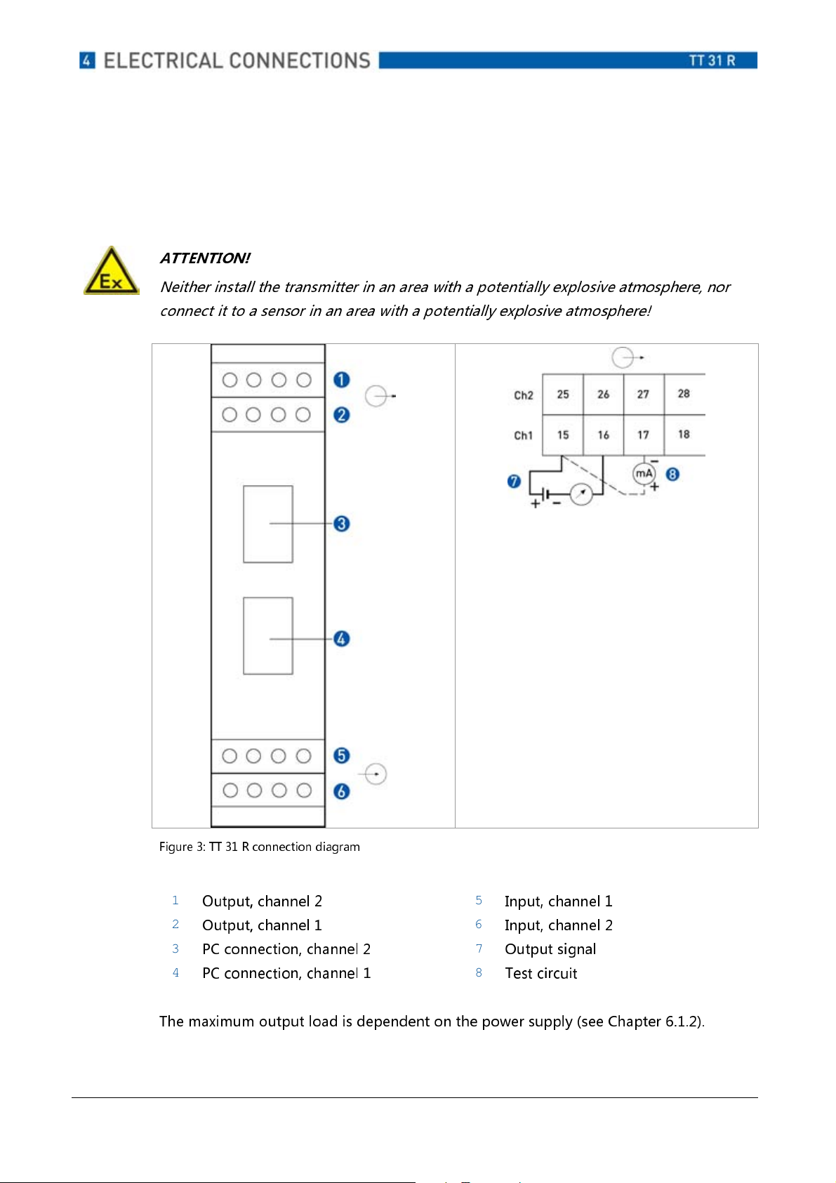
4.3 Connection diagram TT 31 R
ATTENTION!
Neither install the transmitter in an area with a potentially explosive atmosphere, nor
connect it to a sensor in an area with a potentially explosive atmosphere!
Figure 3: TT 31 R connection diagram
1
Output, channel 2
2
Output, channel 1
3
PC connection, channel 2
4
PC connection, channel 1
5
Input, channel 1
6
Input, channel 2
7
Output signal
8
Test circuit
The maximum output load is dependent on the power supply (see Chapter 6.1.2).
02/2011 – 4000753501 – MA OPTITEMP TT31CR R01 en www.krohne.com
12
Page 13
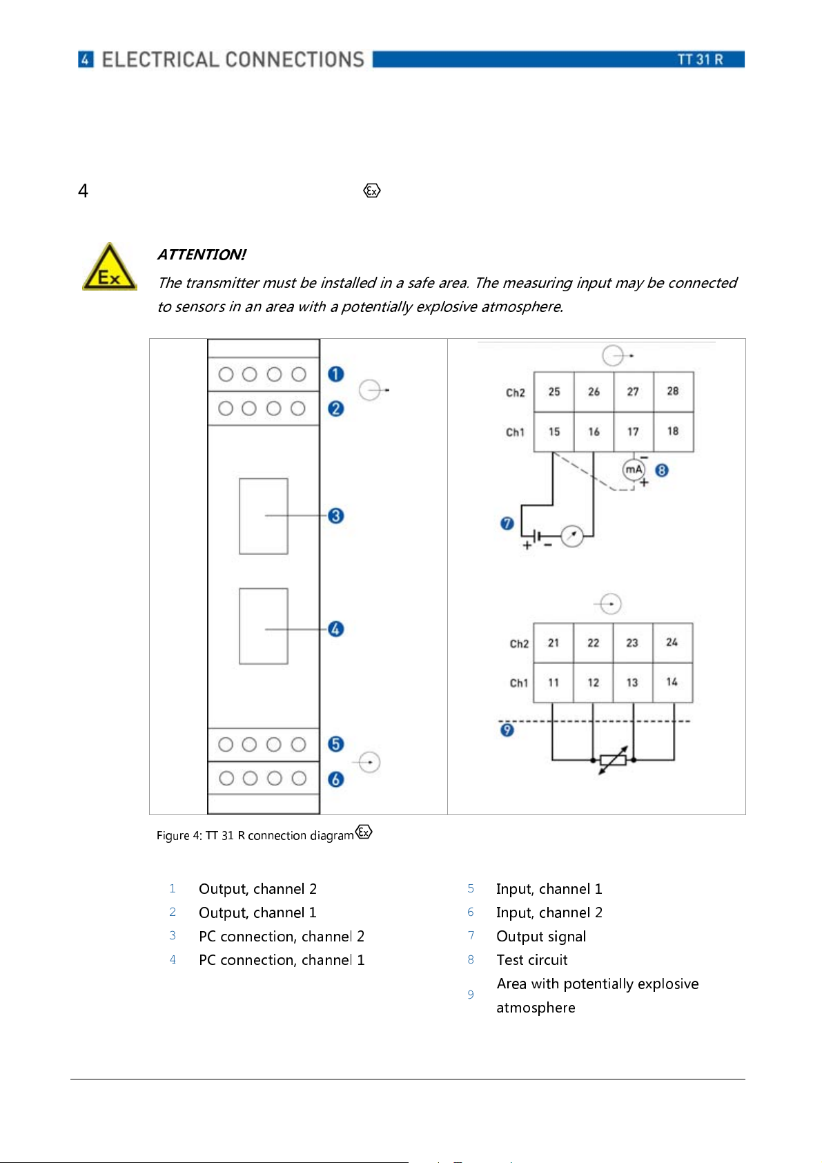
4.4 Connection diagram TT 31 R
ATTENTION!
The transmitter must be installed in a safe area. The measuring input may be connected
to sensors in an area with a potentially explosive atmosphere.
Figure 4: TT 31 R connection diagram
1
Output, channel 2
2
Output, channel 1
3
PC connection, channel 2
4
PC connection, channel 1
5
Input, channel 1
6
Input, channel 2
7
Output signal
8
Test circuit
Area with potentially explosive
9
atmosphere
02/2011 – 4000753501 – MA OPTITEMP TT31CR R01 en www.krohne.com
13
Page 14

The maximum output load is dependent on the power supply (see Chapter 6.1.2).
02/2011 – 4000753501 – MA OPTITEMP TT31CR R01 en www.krohne.com
14
Page 15

4.5 Cable length
ATTENTION!
In the Ex version, please note that the maximum cable length is determined by all of the
cable parameters.
The total capacitance and inductance of the cable must be within the limits for the
transmitter described in the Ex certificate.
To calculate the maximum cable length for the output circuit, determine the total
resistance of the output loop (load resistance plus the approximate cable resistance).
Find out the cable capacitance of the cable being used.
In the case of additional capacitance and inductance of the sensor, these values must be
subtracted from C0 / from L0.
To calculate the maximum cable length, the Ex data must be used.
Input (terminals 11 ... 14, 21 ... 24, intrinsically safe sensor terminals)
I0 = 13 mA
L0 = 100 mH
C0 = 550 nF
Calculation (L
:is indicated in meters)
max
L
= C0/C Value C0 from the Ex data, C = cable capacitance / m
max
L
= L0/L Value L0 from the Ex data, L = cable inductance / m
max
Important note!
Use the smaller of the two calculated values as the maximum cable length.
02/2011 – 4000753501 – MA OPTITEMP TT31CR R01 en www.krohne.com
15
Page 16

5 Operation
5.1 Connection with the KROHNE PC configuration set
ATTENTION!
No PC may be connected to a transmitter in areas with potentially explosive
atmospheres.
If you wish to configure the transmitter with the PC, this must be done outside of the
area with a potentially explosive atmosphere.
Connection, TT 31 R
5.1.1
The transmitter can be configured either with or without voltage supply.
1. Without voltage supply
If the transmitter is connected to the PC with cable type D (offline cable), then it is
supplied with voltage via the PC cable.
Type D
Figure 5: PC connection cable (offline cable)
Order number Comment
Type D VI70IPRP0101
No voltage supply of the
transmitter necessary
02/2011 – 4000753501 – MA OPTITEMP TT31CR R01 en www.krohne.com
16
Page 17

2. With voltage supply
The transmitter is connected to the PC with ATEX cable type A and adapter type C. In
this case the transmitter must be connected to an external voltage supply.
Type A
Cable
Type C
Adapter
Figure 6: PC connection cable ATEX
Order number Comment
Type A (cable) VI70IPRX0002 ATEX certified
Type C
VI70IPRP0001 --
(adapter)
5.1.2 Connection, TT 31 R
If the transmitter is configured with the PC, a configuration cable and an adapter from
the configuration set (order number see Chapter 7.1) must be used as the connection
between the PC and the transmitter.
An ATEX certified cable must be used for transmitters bearing the symbol.
Type A
Cable
02/2011 – 4000753501 – MA OPTITEMP TT31CR R01 en www.krohne.com
Type C
Adapter
17
Page 18

Figure 7: PC connection cable
02/2011 – 4000753501 – MA OPTITEMP TT31CR R01 en www.krohne.com
18
Page 19

Order number Comment
Type A (cable) VI70IPRX0002 ATEX certified
Type C
(adapter)
5.2 General information
CAUTION!
For configuration, the two channel TT 31 R / TT 31 R has on the front side a
separate PC connection for each channel. Connect the cable of the PC configuration
set with the connection of the channel that you wish to configure (see Figure 3).
NOTE!
With the TT 31 R, genuine on-line communication is possible, i.e. access to all functions
during operation. Online communication is only permissible in a safe area.
Ex works setting
VI70IPRP0001 --
The transmitter is shipped with the following settings:
Model Input Output Sensor break
TT 31 R Pt100, 3-wire, 0…100°C 4…20 mA On
TT 31 R Pt100, 3-wire, 0…100°C 4…20 mA On
Configuration is carried out when the PC is "online", i.e. the transmitter can remain in
operation during configuration. During configuration, the output is "frozen", i.e. the
transmitter continues to work with the last value. As soon as configuration has been
completed, the transmitter uses the new parameters.
For configuration, the transmitter must be connected to a supply voltage. If the
transmitter is configured with offline PC cable type D, it is supplied with power via this
cable (see Chapter 5.1.1). The "TempSoft" software is required to configure the
transmitter. The current version is available for downloading on the KROHNE website
http://www.krohne.com/html/dlc/index.shtml.
02/2011 – 4000753501 – MA OPTITEMP TT31CR R01 en www.krohne.com
19
Page 20

Install the "TempSoft" software on your PC, if it is not already installed. During the
installation process, follow the instructions given by the software.
When the transmitter has been configured using the PC, it is ready for operation (no
calibration required).
You can find additional configuration information in the "TempSoft" reference manual.
02/2011 – 4000753501 – MA OPTITEMP TT31CR R01 en www.krohne.com
20
Page 21

5.2.1 Temperature difference measurement
The sensor break function must be deactivated for temperature difference
measurements. In the "Temp Soft" software, the sensor break function must be set to
"Sensor break = without".
Sensor break monitoring
5.2.2
The transmitter uses a pulse signal to determine a sensor break/short circuit. This signal
may interfere with electronic temperature calibrators. To switch off the pulse signal,
deactivate the "Sensor break" function (Sensor break = without) in the "TempSoft"
software.
Action
To protect the PC connections, they must be closed off using the supplied protection
caps after configuration has been completed.
02/2011 – 4000753501 – MA OPTITEMP TT31CR R01 en www.krohne.com
21
Page 22

6 Technical data
6.1 Specifications, TT 31 R / TT 31 R
6.1.1 Technical data
Designation Value
Input
Sensor break function
Output
Ambient temperature
Pt100
Pt1000
-200...
-200...
+1000°C
+200°C
PtX The upper range is dependent on
the X value.
Ni100
Ni1000
Potentiometer
-60...
-10...
0...
2000 Ω
+250°C
+150°C
Thermocouples Types: AE, B, E, J, K, L, N, R, S, T, U
Voltage
-10...
+500 mV
User-defined output
4...
20 mA, 20...4 mA,
temperature linear
TT 31 R
TT 31 R
-20...
-20...
+70°C
+60°C
Galvanic isolation
Power supply
1500 VAC, 1 min
TT 31 R
TT 31 R
8...
36 VDC
8...
36 VDC
Not intrinsically safe
Typical accuracy
Installation
+/- 0.1% of the measuring span
Rail according to EN 50020,
35 mm
Table 1: Technical Data TT 31 R / TT 31 R
02/2011 – 4000753501 – MA OPTITEMP TT31CR R01 en www.krohne.com
22
Page 23

6.1.2 Output load diagram
Figure 8: Output load diagram TT 31 R, TT 31 R
R Total output load [Ω]
U Power supply [VDC]
NOTE
The output load is calculated according to the following formulae:
TT 31 R / TT 31 R R
6.1.3 Dimensions
=(U-8.0)/0.022
LOAD
1
2
3
Dimension
[mm]
115 4.53
100 3.93
22.5 0.88
Dimension
[inch]
Figure 9: Dimensions, TT 31 R/TT 31 R
02/2011 – 4000753501 – MA OPTITEMP TT31CR R01 en www.krohne.com
23
Page 24

6.1.4 Values for input signals, TT 31 R
Inputs 11-14, 21-24
(Intrinsically safe sensor connection)
Uo: ≤ 15 VDC
Io: ≤ 13 mA
Po: ≤
Lo: ~ 100 mH
Co: ~ 550 nF
Table 2: Inputs, TT 31 R
ATTENTION!
The "Input/output/PC isolation" is galvanic isolation, comparable to a Zener barrier. The
TT 31 R can be supplied with an input voltage of <250 V using a non Ex-tested power
supply unit.
02/2011 – 4000753501 – MA OPTITEMP TT31CR R01 en www.krohne.com
24
Page 25

7 Service
7.1 Ordering information TT 31 R
Product Order No.
TT 31 R, 1-Ch. VII2421L0010000
TT 31 R, 2-Ch. VII2422L0010000
TT 31 R (ATEX), 1-Ch. (terminal connection) VII2421LX010000
TT 31 R (ATEX), 2-Ch. (terminal connection) VII2422LX010000
TT 31 R (ATEX), 1-Ch. (plug connection) VII2421LX020000
TT 31 R (ATEX), 2-Ch. (plug connection) VII2422LX020000
Software and cables
PC "TempSoft" configuration set with cable VI70CFG00092
ATEX cable for PC connection
VI70IPRX0002
(included in configuration set VI70CFG00092)
Adapter cable for TT 31 / TT 40
VI70IPRX0001
(included in configuration set VI70CFG00092)
Offline cable for PC connection
VI70IPRX0101
(included in configuration set VI70CFG00092)
Configuration ex works VI70CAL00001
02/2011 – 4000753501 – MA OPTITEMP TT31CR R01 en www.krohne.com
25
Page 26

For your notes:
02/2011 – 4000753501 – MA OPTITEMP TT31CR R01 en www.krohne.com
26
Page 27

For your notes
02/2011 – 4000753501 – MA OPTITEMP TT31CR R01 en www.krohne.com
27
Page 28

 Loading...