

Page 1
Handbook
Handbook
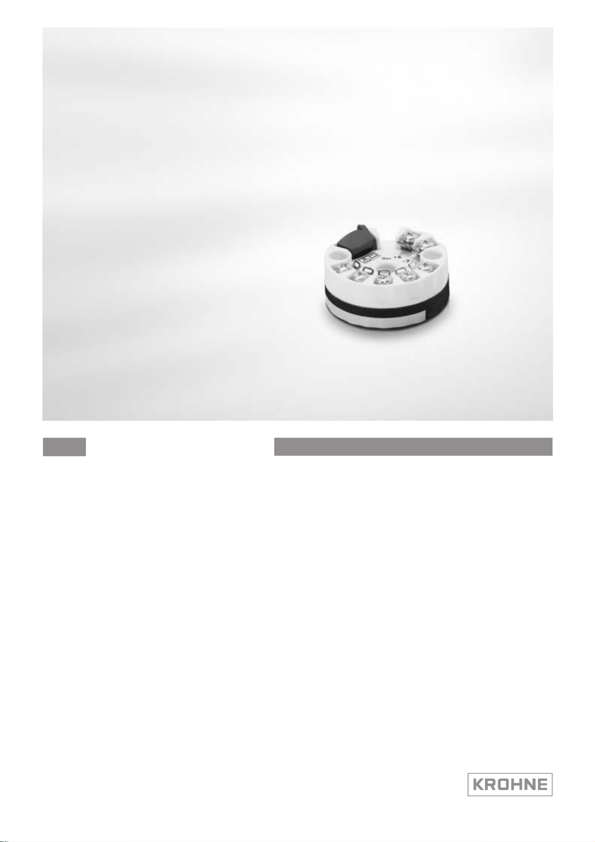
OPTITEMP TT 20
OPTITEMP TT 20
OPTITEMP TT 20OPTITEMP TT 20
HandbookHandbook
Analog PC-programmable two-wire transmitters for
Pt100
The documentation is only complete when used in combination with the relevant
documentation for the sensor.
© KROHNE 10/2011 - 4000753102 - MA OPTITEMP TT 20 R02 en
Page 2

: IMPRINT :::::::::::::::::::::::::::::::::::::::
All rights reserved. It is prohibited to reproduce this documentation, or any part thereof, without
the prior written authorisation of KROHNE Messtechnik GmbH.
Subject to change without notice.
Copyright 2011 by
KROHNE Messtechnik GmbH - Ludwig-Krohne-Str. 5 - 47058 Duisburg (Germany)
2
www.krohne.com 10/2011 - 4000753102 - MA OPTITEMP TT 20 R02 en
Page 3

OPTITEMP TT 20
CONTENTS
1 Safety instructions 5
1.1 Intended use ..................................................................................................................... 5
1.2 Certifications .................................................................................................................... 5
1.3 Safety instructions from the manufacturer ..................................................................... 6
1.3.1 Copyright and data protection ................................................................................................ 6
1.3.2 Disclaimer ............................................................................................................................... 6
1.3.3 Product liability and warranty ................................................................................................ 7
1.3.4 Information concerning the documentation........................................................................... 7
1.3.5 Warnings and symbols used................................................................................................... 8
1.4 Safety instructions for the operator................................................................................. 8
2 Device description 9
2.1 Scope of delivery............................................................................................................... 9
2.2 Device description ............................................................................................................ 9
2.3 Nameplate ...................................................................................................................... 10
3 Installation 11
3.1 Notes on installation ......................................................................................................11
3.2 In-head transmitter........................................................................................................11
3.3 Rail mounting kit for in-head transmitters.................................................................... 13
4 Electrical connections 15
4.1 Safety instructions.......................................................................................................... 15
4.2 Electrical connection diagram ....................................................................................... 15
4.3 Connection diagram ....................................................................................................... 16
5 Operation 17
5.1 Configuration of transmitter .......................................................................................... 17
5.2 Factory calibration of transmitter.................................................................................. 18
5.3 Sensor Break Monotoring (Up/Down scale) .................................................................. 18
5.4 Sensor Short Circuit (Down Scale)................................................................................. 18
5.5 Error Corrections ........................................................................................................... 18
6 Service 19
6.1 Accessory parts .............................................................................................................. 19
6.2 Spare parts availability...................................................................................................19
6.3 Availability of services .................................................................................................... 19
6.4 Returning the device to the manufacturer..................................................................... 19
6.4.1 General information.............................................................................................................. 19
6.4.2 Form (for copying) to accompany a returned device............................................................ 20
6.5 Disposal .......................................................................................................................... 20
www.krohne.com10/2011 - 4000753102 - MA OPTITEMP TT 20 R02 en
3
Page 4

CONTENTS
OPTITEMP TT 20
7 Technical data 21
7.1 Measuring principles...................................................................................................... 21
7.1.1 Resistance thermometer...................................................................................................... 21
7.2 Technical data................................................................................................................. 22
7.3 Dimensions ..................................................................................................................... 25
7.4 Output load diagram....................................................................................................... 25
8 Notes 26
4
www.krohne.com 10/2011 - 4000753102 - MA OPTITEMP TT 20 R02 en
Page 5

OPTITEMP TT 20
1.1 Intended use
The transmitter is an analog two-wire non-isolating PC configured transmitter designed for
Pt100 temperature sensors and intended to be used in an industrial environment.
The transmitter is intended for installation in a B connection head or larger according to
DIN 43729. It's designed for a three wire sensor connection.
The transmitters are configured from a PC by using the ConSoft program and a transmitter
configuration kit (USB connection) ICON without external power supply. Calibration of the
transmitter, after the PC configuration is not necessary.
1.2 Certifications
CE marking
SAFETY INSTRUCTIONS 1
The device fulfils all applicable statutory requirements of the following EC directives:
• CE Directive 93/68/EEC
• EMC Directive 2004/108/EC according harmonized standard EN 61326-1:2006 including A1
and A2
The manufacturer certifies successful testing of the product by applying the CE marking.
www.krohne.com10/2011 - 4000753102 - MA OPTITEMP TT 20 R02 en
5
Page 6

1 SAFETY INSTRUCTIONS
1.3 Safety instructions from the manufacturer
1.3.1 Copyright and data protection
The contents of this document have been created with great care. Nevertheless, we provide no
guarantee that the contents are correct, complete or up-to-date.
The contents and works in this document are subject to copyright. Contributions from third
parties are identified as such. Reproduction, processing, dissemination and any type of use
beyond what is permitted under copyright requires written authorisation from the respective
author and/or the manufacturer.
The manufacturer tries always to observe the copyrights of others, and to draw on works created
in-house or works in the public domain.
The collection of personal data (such as names, street addresses or e-mail addresses) in the
manufacturer's documents is always on a voluntary basis whenever possible. Whenever
feasible, it is always possible to make use of the offerings and services without providing any
personal data.
OPTITEMP TT 20
We draw your attention to the fact that data transmission over the Internet (e.g. when
communicating by e-mail) may involve gaps in security. It is not possible to protect such data
completely against access by third parties.
We hereby expressly prohibit the use of the contact data published as part of our duty to publish
an imprint for the purpose of sending us any advertising or informational materials that we have
not expressly requested.
1.3.2 Disclaimer
The manufacturer will not be liable for any damage of any kind by using its product, including,
but not limited to direct, indirect or incidental and consequential damages.
This disclaimer does not apply in case the manufacturer has acted on purpose or with gross
negligence. In the event any applicable law does not allow such limitations on implied warranties
or the exclusion of limitation of certain damages, you may, if such law applies to you, not be
subject to some or all of the above disclaimer, exclusions or limitations.
Any product purchased from the manufacturer is warranted in accordance with the relevant
product documentation and our Terms and Conditions of Sale.
The manufacturer reserves the right to alter the content of its documents, including this
disclaimer in any way, at any time, for any reason, without prior notification, and will not be liable
in any way for possible consequences of such changes.
6
www.krohne.com 10/2011 - 4000753102 - MA OPTITEMP TT 20 R02 en
Page 7

OPTITEMP TT 20
1.3.3 Product liability and warranty
The operator shall bear responsibility for the suitability of the device for the specific purpose.
The manufacturer accepts no liability for the consequences of misuse by the operator. Improper
installation and operation of the devices (systems) will cause the warranty to be void. The
respective "Standard Terms and Conditions" which form the basis for the sales contract shall
also apply.
1.3.4 Information concerning the documentation
To prevent any injury to the user or damage to the device it is essential that you read the
information in this document and observe applicable national standards, safety requirements
and accident prevention regulations.
If this document is not in your native language and if you have any problems understanding the
text, we advise you to contact your local office for assistance. The manufacturer can not accept
responsibility for any damage or injury caused by misunderstanding of the information in this
document.
This document is provided to help you establish operating conditions, which will permit safe and
efficient use of this device. Special considerations and precautions are also described in the
document, which appear in the form of underneath icons.
SAFETY INSTRUCTIONS 1
www.krohne.com10/2011 - 4000753102 - MA OPTITEMP TT 20 R02 en
7
Page 8
1 SAFETY INSTRUCTIONS
1.3.5 Warnings and symbols used
Safety warnings are indicated by the following symbols.
DANGER!
This information refers to the immediate danger when working with electricity.
DANGER!
This warning refers to the immediate danger of burns caused by heat or hot surfaces.
DANGER!
This warning refers to the immediate danger when using this device in a hazardous atmosphere.
DANGER!
These warnings must be observed without fail. Even partial disregard of this warning can lead to
serious health problems and even death. There is also the risk of seriously damaging the device
or parts of the operator's plant.
OPTITEMP TT 20
WARNING!
Disregarding this safety warning, even if only in part, poses the risk of serious health problems.
There is also the risk of damaging the device or parts of the operator's plant.
CAUTION!
Disregarding these instructions can result in damage to the device or to parts of the operator's
plant.
INFORMATION!
These instructions contain important information for the handling of the device.
LEGAL NOTICE!
This note contains information on statutory directives and standards.
• HANDLING
HANDLING
HANDLINGHANDLING
This symbol designates all instructions for actions to be carried out by the operator in the
specified sequence.
i RESULT
RESULT
RESULTRESULT
This symbol refers to all important consequences of the previous actions.
1.4 Safety instructions for the operator
WARNING!
In general, devices from the manufacturer may only be installed, commissioned, operated and
maintained by properly trained and authorized personnel.
This document is provided to help you establish operating conditions, which will permit safe and
efficient use of this device.
8
www.krohne.com 10/2011 - 4000753102 - MA OPTITEMP TT 20 R02 en
Page 9

OPTITEMP TT 20
2.1 Scope of delivery
INFORMATION!
Inspect the cartons carefully for damages or signs of rough handling. Report damage to the
carrier and to the local office of the manufacturer.
INFORMATION!
Do a check of the packing list to make sure that you have all the elements given in the order.
INFORMATION!
Look at the device nameplate to ensure that the device is delivered according to your order.
The scope of delivery always consists of the transmitter and its documentation.
2.2 Device description
The transmitter will indicate sensor break according to selected value high (> 21.0 mA) or low
(< 3.6 mA). Short circuit will always be indicated as low output (< 3.6 mA).
DEVICE DESCRIPTION 2
The transmitter is designed for installation in a B connection head according to DIN 43729. With
an installation kit the transmitter can be installed on a top-hat rail according to DIN EN 50022.
The transmitters are configured from a PC by using the ConSoft program and a transmitter
configuration kit ICON. When transmitters are configured from PC no calibration is necessary.
The PC configuration software ConSoft is used for configuration, display and documentation. The
current ConSoft version is available for downloading on our website.
You can find configuration instructions in the ConSoft reference manual.
ConSoft is compatible with Windows 2000, Windows XP, Windows Vista and Windows 7.
www.krohne.com10/2011 - 4000753102 - MA OPTITEMP TT 20 R02 en
9
Page 10

2 DEVICE DESCRIPTION
2.3 Nameplate
INFORMATION!
Look at the device nameplate to ensure that the device is delivered according to your order.
The transmitter can be identified by the information on the nameplates.
Figure 2-1: Example for round nameplate
1 Product name
2 Recycling
3 CE marking (EC conformity)
4 Part number, serial number and batch number
5 Connections
6 Manufacturer and address
7 Printable field, sensor configuration
OPTITEMP TT 20
10
www.krohne.com 10/2011 - 4000753102 - MA OPTITEMP TT 20 R02 en
Page 11

OPTITEMP TT 20
3.1 Notes on installation
INFORMATION!
Inspect the cartons carefully for damages or signs of rough handling. Report damage to the
carrier and to the local office of the manufacturer.
INFORMATION!
Do a check of the packing list to make sure that you have all the elements given in the order.
INFORMATION!
Look at the device nameplate to ensure that the device is delivered according to your order.
3.2 In-head transmitter
The transmitter is intended for installation in DIN B connection heads or larger. The large
Ø7 mm / 0.28 inch center hole facilitates the electrical connection of the sensor and the
installation. For detailed information refer to
Dimensions
INSTALLATION 3
on page 25.
Figure 3-1: Connection head installation kit
1 M4 screw
2 Spring
3 Lock washer
4 Wires from the measuring inserts
5 MI Cable
INFORMATION!
The connection head installation kit does not belong to the standard scope of delivery of the
transmitter, you have to order it separately. For more information refer to Accessory parts on
page 19
.
www.krohne.com10/2011 - 4000753102 - MA OPTITEMP TT 20 R02 en
11
Page 12

3 INSTALLATION
WARNING!
The transmitter has been developed for an operating temperature of -40...+85
To avoid destruction or damage of the device, always assure that the operating temperature or
ambient temperature does not exceed the permissible range. The thermowell also transfer the
process temperature to the transmitter housing. If the process temperature is close to or
exceeds the maximum temperature of the transmitter, then the temperature in the transmitter
housing can rise above the maximum permissible temperature. One way to decrease the head
transfer via thermowell is to install the transmitter further away from the heat source. Inversely
similar measurements can be done if the temperature gets below specified minimum
temperature.
OPTITEMP TT 20
°
C/ -40°F...+185°F.
12
www.krohne.com 10/2011 - 4000753102 - MA OPTITEMP TT 20 R02 en
Page 13

OPTITEMP TT 20
3.3 Rail mounting kit for in-head transmitters
INFORMATION!
The rail mounting kit allows to install the in-head transmitter on a rail according to DIN 50022.
The kit does not belong to the standard scope of delivery. You have to order it separately. For
more information refer to Accessory parts on page 19
The screws in the kit is not to be used with this transmitter.
Rail mounting kit for in-head transmitters
INSTALLATION 3
.
Figure 3-2: Rail mounting kit for in-head transmitters
1 Rail (not included in the kit)
2 Screws (not needed)
3 Clamp
4 Transmitter
Installation procedure: Step 1
1 Place the transmitter on the rail mounting kit as shown above.
2 Push the transmitter down until it reaches the plate and is attached.
www.krohne.com10/2011 - 4000753102 - MA OPTITEMP TT 20 R02 en
13
Page 14

3 INSTALLATION
Installation procedure: Step 2
1 Hook one end of the installation the kit into the rail as shown above.
2 Push the other end of the the kit down until it snaps onto the rail.
3 Release by pushing the hook, shown in the picture, and at the same time lift the clip out of the
rail.
OPTITEMP TT 20
14
www.krohne.com 10/2011 - 4000753102 - MA OPTITEMP TT 20 R02 en
Page 15

OPTITEMP TT 20
4.1 Safety instructions
DANGER!
All work on the electrical connections may only be carried out with the power disconnected.
DANGER!
Observe the corresponding regulations, declarations of conformity, the type test certificate of
the device and the relevant instructions of this manual.
CAUTION!
Before you connect and operate a transmitter, always note the following items to avoid an
electric shock:
•
For all work on the electrical connections use an electrostatic safe (i.e. grounded)
workplace! In this way you minimize the risk of electrostatic discharge (ESD).
WARNING!
Observe without fail the local occupational health and safety regulations. Any work done on the
electrical components of the measuring device may only be carried out by properly trained
specialists.
ELECTRICAL CONNECTIONS 4
INFORMATION!
Look at the device nameplate to ensure that the device is delivered according to your order.
INFORMATION!
The transmitter is protected against polarity reversal. No damage will occur to the device if the
polarity of the supply voltage is switched. The output will then indicate 0 mA.
4.2 Electrical connection diagram
INFORMATION!
To avoid measuring errors, all cables must be connected properly and the screws tightened
correctly.
Figure 4-1: Pt100, 3-wire connection
INFORMATION!
The transmitter has a polarity protection, connecting the power supply with wrong polarity will
not harm the transmitter.
www.krohne.com10/2011 - 4000753102 - MA OPTITEMP TT 20 R02 en
15
Page 16

4 ELECTRICAL CONNECTIONS
4.3 Connection diagram
CAUTION!
Always establish the electrical connections according to the following diagrams. Otherwise it
can come to destruction or damage of the transmitter. Note that the maximum output load
always depends on the power supply. If the maximum output load is exceeded, then the
measured value will become incorrect. For further information refer to the output load diagram
in the chapter "Technical data" on page 25
OPTITEMP TT 20
.
Figure 4-2: Connection diagram
1 Voltage supply 8.5...32 VDC (terminals 6,7)
2 R
Load
3 Input
4 Output signal (4...20mA)
5 Pt100 3-wire connection
16
www.krohne.com 10/2011 - 4000753102 - MA OPTITEMP TT 20 R02 en
Page 17

OPTITEMP TT 20
5.1 Configuration of transmitter
The transmitters are configured from a PC by using the ConSoft program and a transmitter
configuration kit ICON. For more information refer to
The ConSoft is a PC based graphical user interface for configuration of the transmitters. The PC
configuration software ConSoft is used for configuration, display and documentation.
Full functionality of the transmitter is achieved with ConSoft program version 2.0.0.1 or later.
Consoft is compatible with Windows 2000 SP3, Windows XP (SP2+), Windows Vista, and
Windows 7.The current software versions of ConSoft and the USB interface are available for
downloading on our website.
Configuration can be performed with or without connected power supply.
To make a configuration of the transmitter you need to do following:
1 Install the PC configuration software ConSoft in your PC.
2 Install the driver for the Transmitter configuration kit ICON (included in the Transmitter con-
figuration kit ICON). See User instructions for Transmitter configuration kit ICON. USB inter-
face will indicate correct installation and connection of the transmitter – ICON – PC.
3 Connect the transmitter to your PC via the Transmitter configuration kit ICON.
4 Start the software ConSoft.
5 Click on the icon "Read from the transmitter" or File - "Read from the transmitter". The soft-
ware will identify and connect to the transmitter. A configuration window for the connected
transmitter will open.
6 Enter one of the following options:
- Temperature sensor - Pt100 type (3 different standards)
- Measuring range - lower range value and upper range value
- Error monitoring - upscale or downscale action at sensor break indication
- Error correction - sensor error lower and upper values - compensation for known sensor
errors
- Custom settings - Tag number
7 The selected configuration is downloaded to the transmitter by clicking the icon "Transfer to
transmitter" or File - "Transfer to transmitter"
8 The transmitter begins using the new parameters directly after downloading.
Accessory parts
OPERATION 5
on page 19.
CAUTION!
Only use the manufacturer's configuration kit for PC configuration. Another configuration kit
could destroy or damage the transmitter.
www.krohne.com10/2011 - 4000753102 - MA OPTITEMP TT 20 R02 en
17
Page 18

5 OPERATION
Figure 5-1: Connection during configuration of in-head transmitter
a = PC configuration kit; b = PC software ConSoft
1 Input
2 R
Load
3 Output voltage supply (terminals 6 and 7)
4 Communication with USB interface and a PC software ConSoft
5.2 Factory calibration of transmitter
OPTITEMP TT 20
The transmitters are delivered with a factory configuration Pt100 (α = 0.00385), 3-wire
connection 0...+100 °C / +32...+212 °F or configured according to customer’s requirements.
Due to the long-term drift of max. ±0.1% of span per year, a re-calibration of the
transmitter is normally not needed. Should you for any reason require the re-calibration, the
transmitter must be returned to the factory.
5.3 Sensor Break Monotoring (Up/Down scale)
In case the sensor breakes the transmitter will indicate this by either drop the output <3.6 mA or
lift it to >21.0 mA. The diffrent indication is set in the transmitter via configurator.
5.4 Sensor Short Circuit (Down Scale)
In case the sensor short circuit the transmitter indicates this by dropping the output <3.6 mA and
is default.
5.5 Error Corrections
By setting the measured min and max value for the sensor in given temperature range the
transmitter can compensate sensor errors. This is set with help of the configurator.
18
www.krohne.com 10/2011 - 4000753102 - MA OPTITEMP TT 20 R02 en
Page 19

OPTITEMP TT 20
6.1 Accessory parts
Accessory part Order code
Universal rail mounting kit for in-head version 70ADA00027
Configuration kit including modem, software Consoft and cables for USB
connection
Connection Head installation kit 70ADA00017
6.2 Spare parts availability
The manufacturer adheres to the basic principle that functionally adequate spare parts for each
device or each important accessory part will be kept available for a period of 3 years after
delivery of the last production run for the device.
This regulation only applies to spare parts which are subject to wear and tear under normal
operating conditions.
6.3 Availability of services
SERVICE 6
4001107901
The manufacturer offers a range of services to support the customer after expiration of the
warranty. These include repair, maintenance, technical support and training.
INFORMATION!
For more precise information, please contact your local representative.
6.4 Returning the device to the manufacturer
6.4.1 General information
This device has been carefully manufactured and tested. If installed and operated in accordance
with these operating instructions, it will rarely present any problems.
CAUTION!
Should you nevertheless need to return a device for inspection or repair, please pay strict
attention to the following points:
•
Due to statutory regulations on environmental protection and safeguarding the health and
safety of our personnel, manufacturer may only handle, test and repair returned devices that
have been in contact with products without risk to personnel and environment.
•
This means that the manufacturer can only service this device if it is accompanied by the
following certificate (see next section) confirming that the device is safe to handle.
CAUTION!
If the device has been operated with toxic, caustic, flammable or water-endangering products,
you are kindly requested:
•
to check and ensure, if necessary by rinsing or neutralizing, that all cavities are free from
such dangerous substances,
•
to enclose a certificate with the device confirming that is safe to handle and stating the
product used.
www.krohne.com10/2011 - 4000753102 - MA OPTITEMP TT 20 R02 en
19
Page 20

6 SERVICE
6.4.2 Form (for copying) to accompany a returned device
Company: Address:
Department: Name:
Tel. no.: Fax no.:
Manufacturer's order no. or serial no.:
The device has been operated with the following medium:
OPTITEMP TT 20
This medium is: water-hazardous
toxic
caustic
flammable
We checked that all cavities in the device are free from such
substances.
We have flushed out and neutralized all cavities in the
device.
We hereby confirm that there is no risk to persons or the environment through any residual media
contained in the device when it is returned.
Date: Signature:
Stamp:
6.5 Disposal
CAUTION!
Disposal must be carried out in accordance with legislation applicable in your country.
20
www.krohne.com 10/2011 - 4000753102 - MA OPTITEMP TT 20 R02 en
Page 21

OPTITEMP TT 20
7.1 Measuring principles
The kind of the measuring principle depends on the measuring insert that you combine with the
transmitter. In matters of the thermometer type the manufacturer offers two different
measuring inserts, either with a resistance thermometer or with a thermocouple. This
transmitter only supports resistance thermometer.
7.1.1 Resistance thermometer
The measuring insert with a resistance thermometer features a temperature-sensitive sensor
made from a platinum RTD, whose value at 0°C / +32°F is 100 Ω. That is where the name "Pt100"
comes from.
It is generally valid that the electric resistance of metals increases according to a mathematical
function as the temperature rises. This effect is taken advantage of by resistance thermometers
to measure temperature. The "Pt100" thermometer features a measuring resistance with
defined characteristics, standardised in IEC 60751. The same is true for the tolerances. The
average temperature coefficient of a Pt100 is 3.85 x 10
+32...+212°F.
TECHNICAL DATA 7
-3K-1
in the range from 0...+100°C/
During operation, a constant current I (≤ 1 mA) flows through the Pt100 RTD, which brings about
a voltage drop U. The resistance R is calculated using Ohm's Law (R=U/I). As the voltage drop U
at 0°C / +32°F is 100 mV, the resulting resistance of the Pt100 thermometer is 100 Ω (100 mV /
1 mA = 100 Ω).
Figure 7-1: Pt100 resistance thermometer in 4-wire connection at 0°C / +32°F, schematic.
1 Pt100 RTD
2 Voltage meter
3 Current source
www.krohne.com10/2011 - 4000753102 - MA OPTITEMP TT 20 R02 en
21
Page 22

7 TECHNICAL DATA
OPTITEMP TT 20
7.2 Technical data
INFORMATION!
•
The following data is provided for general applications. If you require data that is more
relevant to your specific application, please contact us or your local representative.
•
Additional information (certificates, special tools, software,...) and complete product
documentation can be downloaded free of charge from the website (Download Center).
Measuring system
Application range Temperature measurements of solids, liquids and gases in industrial
Design
Versions
Versions
VersionsVersions
TT 20 In-head transmitters which are intended for installation in a "B connection
Features
Features
FeaturesFeatures
Sensor matching A matching to a calibrated temperature sensor can easily be performed by
PC programmable Input type and measuring ranges are set from PC.
environment.
head" or larger according to DIN 43729.
entering the sensor deviation in the low and high ends of the measuring
ranges.
Full accuracy is provided without any need for calibration.
Configuration without external power.
Edit/Read configuration offline, i.e. without power supply, by just connecting
to a USB port of a PC.
Measuring accuracy
Accuracy & Stability Basic accuracy is max. of ±0.1% of span.
Temperature influence Deviation from +20°C / +68°F
Supply voltage influence Negligible
Long-term drift ±0.1% of span per year
Max. of ±0.25°C / 25°C or ±0.25% / 25°C
Max. of ±0.5°F / 50°F or ±0.28% / 50°F
Operating conditions
Temperature
Temperature
TemperatureTemperature
In-head transmitter Operating and storage temperature:
Humidity 0...100% RH (non-condensing)
Protection category
Protection category
Protection categoryProtection category
In-head transmitter Protection housing: IP65
Operating and storage temperature:
Operating and storage temperature:Operating and storage temperature:
Standard version: -40...+85°C / -40...+185°F
Protection terminals: IP10
Installation conditions
Mounting In-head transmitter: DIN B-head or larger, DIN-rail (with adapter)
For detailed information refer to
Weight In-head transmitter: 32 g / 0.07 lb
Dimensions For detailed information refer to
Installation
Dimensions
on page 11.
on page 25.
22
www.krohne.com 10/2011 - 4000753102 - MA OPTITEMP TT 20 R02 en
Page 23

OPTITEMP TT 20
TECHNICAL DATA 7
Materials
Housing PC/ABS + PA
Flammability acc. to UL In-head transmitter: V0
Electrical connections
Power supply Standard: 8.5...32 VDC
Isolation Not galvanically isolated
Connection
Polarity Protection Standard
Single/stranded wires: max. 1.5 mm2/ AWG 16
Inputs / Outputs
Input - RTD
Input - RTD
Input - RTDInput - RTD
Pt100 (IEC 60751, α=0.00385) -50... +850°C / -58...+1562°F
Pt100 (JIS C 1604-8, α=0.003916)
Pt100 (US, α=0,003902
Sensor current ≤0.5 mA
Maximum sensor wire resistance 20 Ω/wire
Adjustment Zero adjustment -50, -25, 0, +25, +50°C / -58, -13, +32, +77, +122°F
Minimum span +20°C / +68°F
Sensor error compensation ±1% of span
Output
Output
OutputOutput
Output signal 4...20 mA
Permissible load 700 Ω at 24 VDC
NAMUR compliance Failure currents acc. to NAMUR NE 43 except short circuit detection were
Respons time <50 ms
Monitoring Sensor break monitoring, selectable, upscale ≥21.0 mA or downscale
Configuration
Configuration
ConfigurationConfiguration
ConSoft The PC configuration software, ConSoft, is a versatile and user-friendly tool
Temperature linear
downscale is the only option.
≤3.6 mA action
Sensor short-circuit, fixed, downscale ≤3.6 mA action
for transmitter configuration.
Consoft is compatible with Windows 2000 (SP3), Windows XP (SP2+),
Windows Vista, and Windows 7.
ConSoft is part of the complete configuration kit ICON, which also contains a
USB Interface and necessary cables.
www.krohne.com10/2011 - 4000753102 - MA OPTITEMP TT 20 R02 en
23
Page 24

7 TECHNICAL DATA
OPTITEMP TT 20
Approvals and certifications
CE The device fulfils the statutory requirements of the EC directives.
Other standards and approvals
Other standards and approvals
Other standards and approvalsOther standards and approvals
Electromagnetic compatibility Directive: 2004/108/EC
Vibration resistance Acc. to IEC 60068-2-6, test Fc, 84...2000 Hz, 10 g
Shock resistance Acc. to IEC 60068-2-31, test Ec
The manufacturer certifies that these requirements have been met by
applying the CE marking.
Harmonized standards: EN 61326-1:2006
ESD, Radiated EM-field: Criteria A
Surge: ~3% of span
Burst, conducted RF: ~1% of span
24
www.krohne.com 10/2011 - 4000753102 - MA OPTITEMP TT 20 R02 en
Page 25

OPTITEMP TT 20
7.3 Dimensions
In-head transmitter
In-head transmitter
In-head transmitterIn-head transmitter
a 33.0 1.30
b 7.0 0.28
c 44.5 1.75
d 18.5 0.72
TECHNICAL DATA 7
Dimensions
[mm] [inch]
7.4 Output load diagram
Formula for the maximum permissible output load:
permissible R
[Ω] = (U-8.5)/0.022
Load
Figure 7-2: Output load diagram
X: Power supply U [VDC]
Y: Total output load R [Ω]
www.krohne.com10/2011 - 4000753102 - MA OPTITEMP TT 20 R02 en
25
Page 26

8 NOTES
OPTITEMP TT 20
26
www.krohne.com 10/2011 - 4000753102 - MA OPTITEMP TT 20 R02 en
Page 27

OPTITEMP TT 20
NOTES 8
www.krohne.com10/2011 - 4000753102 - MA OPTITEMP TT 20 R02 en
27
Page 28

KROHNE product overview
• Electromagnetic flowmeters
• Variable area flowmeters
• Ultrasonic flowmeters
• Mass flowmeters
• Vortex flowmeters
• Flow controllers
• Level meters
• Temperature meters
• Pressure meters
• Analysis products
• Measuring systems for the oil and gas industry
• Measuring systems for sea-going tankers
Head Office KROHNE Messtechnik GmbH
Ludwig-Krohne-Str. 5
D-47058 Duisburg (Germany)
Tel.:+49 (0)203 301 0
Fax:+49 (0)203 301 10389
info@krohne.de
© KROHNE 10/2011 - 4000753102 - MA OPTITEMP TT 20 R02 en - Subject to change without notice.
The current list of all KROHNE contacts and addresses can be found at:
www.krohne.com
 Loading...