

Page 1

Handbook
Handbook
OPTITEMP TT 11 C/R
OPTITEMP TT 11 C/R
OPTITEMP TT 11 C/ROPTITEMP TT 11 C/R
HandbookHandbook
Analogue 3-wire temperature transmitter
The documentation is only complete when used in combination with the relevant
documentation for the sensor.
© KROHNE 05/2011 - 4000752902 - MA OPTITEMP TT 11 C/R R02 en
Page 2

: IMPRINT :::::::::::::::::::::::::::::::::::::::
OPTITEMP TT 11 C/R
All rights reserved. It is prohibited to reproduce this documentation, or any part thereof, without
the prior written authorisation of KROHNE Messtechnik GmbH.
Subject to change without notice.
Copyright 2011 by
KROHNE Messtechnik GmbH - Ludwig-Krohne-Str. 5 - 47058 Duisburg (Germany)
2
www.krohne.com 05/2011 - 4000752902 - MA OPTITEMP TT 11 C/R R02 en
Page 3

OPTITEMP TT 11 C/R
CONTENTS
1 Safety instructions 5
1.1 Intended use ..................................................................................................................... 5
1.2 Certifications .................................................................................................................... 5
1.2.1 EC directive compliance ......................................................................................................... 5
1.3 Safety instructions from the manufacturer ..................................................................... 6
1.3.1 Copyright and data protection ................................................................................................ 6
1.3.2 Disclaimer ............................................................................................................................... 6
1.3.3 Product liability and warranty ................................................................................................ 7
1.3.4 Information concerning the documentation........................................................................... 7
1.3.5 Warnings and symbols used................................................................................................... 8
1.4 Safety instructions for the operator................................................................................. 8
2 Device description 9
2.1 Scope of delivery............................................................................................................... 9
2.2 General description .......................................................................................................... 9
2.3 Nameplate ...................................................................................................................... 10
2.3.1 In-head transmitter .............................................................................................................. 10
2.3.2 Rail-mount transmitter ........................................................................................................ 11
3 Installation 12
3.1 Notes on installation ......................................................................................................12
3.2 In-head transmitter........................................................................................................12
3.3 Rail mounting kit for in-head transmitters.................................................................... 14
3.4 Rail-mount transmitter .................................................................................................. 15
4 Electrical connections 16
4.1 Safety instructions.......................................................................................................... 16
4.2 Electrical input connections........................................................................................... 17
4.2.1 In-head transmitter .............................................................................................................. 17
4.2.2 Rail-mount transmitter ........................................................................................................ 17
4.3 Electrical connection diagrams ..................................................................................... 17
4.3.1 In-head transmitter .............................................................................................................. 18
4.3.2 Rail-mount transmitter ........................................................................................................ 19
5 Operation 21
5.1 Configuring the in-head version..................................................................................... 21
5.2 Configuration example (in-head version) ...................................................................... 23
5.3 Configuring the rail-mount version ............................................................................... 24
5.4 Configuration example (rail-mount version) ................................................................. 26
5.5 Calibration ...................................................................................................................... 26
www.krohne.com05/2011 - 4000752902 - MA OPTITEMP TT 11 C/R R02 en
3
Page 4

CONTENTS
OPTITEMP TT 11 C/R
6 Service 29
6.1 Accessory parts .............................................................................................................. 29
6.2 Spare parts availability...................................................................................................29
6.3 Availability of services .................................................................................................... 29
6.4 Returning the device to the manufacturer..................................................................... 30
6.4.1 General information.............................................................................................................. 30
6.4.2 Form (for copying) to accompany a returned device............................................................ 31
6.5 Disposal .......................................................................................................................... 31
7 Technical data 32
7.1 Resistance thermometer ............................................................................................... 32
7.2 Technical data................................................................................................................. 33
7.3 Dimensions ..................................................................................................................... 35
8 Notes 37
4
www.krohne.com 05/2011 - 4000752902 - MA OPTITEMP TT 11 C/R R02 en
Page 5
OPTITEMP TT 11 C/R
1.1 Intended use
DANGER!
Neither operate this transmitter in potentially explosive areas, nor connect it to a sensor located
in a potentially explosive area! Otherwise the transmitter might cause an explosion that can
result in fatal injuries!
DANGER!
Responsibility for the correct use of the devices with special regard to suitability, intended use
and the field of application lies solely with the operator. To avoid any kind of incorrect use, also
note the information in the chapter "Device description".
DANGER!
The transmitters do not contain any serviceable parts inside. Always send defective devices to
the manufacturer or the local distributor for repair or exchange. If this is the case, attach a clear
description of the malfunction for warranty claims.
INFORMATION!
The manufacturer is not liable for any damage resulting from improper use or use for other than
the intended purpose. To avoid any kind of incorrect use, also note the information in the chapter
"Device description"!
SAFETY INSTRUCTIONS 1
The manufacturer has constructed these transmitters only for temperature measurements with
single resistance thermometers of the type Pt100 and Pt1000. The main field of application are
building services applications.
1.2 Certifications
1.2.1 EC directive compliance
CE marking
The device fulfils all applicable statutory requirements of the following EC directives:
• EMC Directive 2004/108/EC, harmonized standard EN 61326-1:2006
• CE Directive 93/68/EEC
The manufacturer certifies successful testing of the product by applying the CE marking.
www.krohne.com05/2011 - 4000752902 - MA OPTITEMP TT 11 C/R R02 en
5
Page 6

1 SAFETY INSTRUCTIONS
1.3 Safety instructions from the manufacturer
1.3.1 Copyright and data protection
The contents of this document have been created with great care. Nevertheless, we provide no
guarantee that the contents are correct, complete or up-to-date.
The contents and works in this document are subject to copyright. Contributions from third
parties are identified as such. Reproduction, processing, dissemination and any type of use
beyond what is permitted under copyright requires written authorisation from the respective
author and/or the manufacturer.
The manufacturer tries always to observe the copyrights of others, and to draw on works created
in-house or works in the public domain.
The collection of personal data (such as names, street addresses or e-mail addresses) in the
manufacturer's documents is always on a voluntary basis whenever possible. Whenever
feasible, it is always possible to make use of the offerings and services without providing any
personal data.
OPTITEMP TT 11 C/R
We draw your attention to the fact that data transmission over the Internet (e.g. when
communicating by e-mail) may involve gaps in security. It is not possible to protect such data
completely against access by third parties.
We hereby expressly prohibit the use of the contact data published as part of our duty to publish
an imprint for the purpose of sending us any advertising or informational materials that we have
not expressly requested.
1.3.2 Disclaimer
The manufacturer will not be liable for any damage of any kind by using its product, including,
but not limited to direct, indirect or incidental and consequential damages.
This disclaimer does not apply in case the manufacturer has acted on purpose or with gross
negligence. In the event any applicable law does not allow such limitations on implied warranties
or the exclusion of limitation of certain damages, you may, if such law applies to you, not be
subject to some or all of the above disclaimer, exclusions or limitations.
Any product purchased from the manufacturer is warranted in accordance with the relevant
product documentation and our Terms and Conditions of Sale.
The manufacturer reserves the right to alter the content of its documents, including this
disclaimer in any way, at any time, for any reason, without prior notification, and will not be liable
in any way for possible consequences of such changes.
6
www.krohne.com 05/2011 - 4000752902 - MA OPTITEMP TT 11 C/R R02 en
Page 7

OPTITEMP TT 11 C/R
1.3.3 Product liability and warranty
The operator shall bear responsibility for the suitability of the device for the specific purpose.
The manufacturer accepts no liability for the consequences of misuse by the operator. Improper
installation and operation of the devices (systems) will cause the warranty to be void. The
respective "Standard Terms and Conditions" which form the basis for the sales contract shall
also apply.
1.3.4 Information concerning the documentation
To prevent any injury to the user or damage to the device it is essential that you read the
information in this document and observe applicable national standards, safety requirements
and accident prevention regulations.
If this document is not in your native language and if you have any problems understanding the
text, we advise you to contact your local office for assistance. The manufacturer can not accept
responsibility for any damage or injury caused by misunderstanding of the information in this
document.
This document is provided to help you establish operating conditions, which will permit safe and
efficient use of this device. Special considerations and precautions are also described in the
document, which appear in the form of underneath icons.
SAFETY INSTRUCTIONS 1
www.krohne.com05/2011 - 4000752902 - MA OPTITEMP TT 11 C/R R02 en
7
Page 8

1 SAFETY INSTRUCTIONS
1.3.5 Warnings and symbols used
Safety warnings are indicated by the following symbols.
DANGER!
This information refers to the immediate danger when working with electricity.
DANGER!
This warning refers to the immediate danger of burns caused by heat or hot surfaces.
DANGER!
This warning refers to the immediate danger when using this device in a hazardous atmosphere.
DANGER!
These warnings must be observed without fail. Even partial disregard of this warning can lead to
serious health problems and even death. There is also the risk of seriously damaging the device
or parts of the operator's plant.
OPTITEMP TT 11 C/R
WARNING!
Disregarding this safety warning, even if only in part, poses the risk of serious health problems.
There is also the risk of damaging the device or parts of the operator's plant.
CAUTION!
Disregarding these instructions can result in damage to the device or to parts of the operator's
plant.
INFORMATION!
These instructions contain important information for the handling of the device.
LEGAL NOTICE!
This note contains information on statutory directives and standards.
• HANDLING
HANDLING
HANDLINGHANDLING
This symbol designates all instructions for actions to be carried out by the operator in the
specified sequence.
i RESULT
RESULT
RESULTRESULT
This symbol refers to all important consequences of the previous actions.
1.4 Safety instructions for the operator
WARNING!
In general, devices from the manufacturer may only be installed, commissioned, operated and
maintained by properly trained and authorized personnel.
This document is provided to help you establish operating conditions, which will permit safe and
efficient use of this device.
8
www.krohne.com 05/2011 - 4000752902 - MA OPTITEMP TT 11 C/R R02 en
Page 9

OPTITEMP TT 11 C/R
2.1 Scope of delivery
The scope of delivery always consists of the transmitter and its documentation.
2.2 General description
TT 11 C
TT 11 C
TT 11 CTT 11 C
The TT 11 C is an analogue multi-range 3-wire in-head transmitter for temperature
measurements. It works together with measuring resistors of the types Pt100 and Pt1000. The
device has an output with the range 0...10 VDC; the manufacturer has designed the transmitter
especially for building services applications as HVAC systems often require a signal in the range
of 0...10 V.
The in-head transmitter is intended for installation in a "B connection head" or larger according
to DIN 43729. As an alternative you can also mount the in-head version on a rail according to
DIN EN 50022 with the help of the rail mounting kit (further information on page 14).
DEVICE DESCRIPTION 2
TT 11 R
TT 11 R
TT 11 RTT 11 R
The TT 11 R is an analogue 3-wire rail-mount transmitter for temperature measurements with
the same features as the in-head version.
The rail-mount transmitter is intended for installation on a rail according to DIN 50022.
INFORMATION!
In the standard delivery condition the transmitters are not preset. Therefore you have to make a
complete solder pad configuration before using the transmitter for the first time (refer to
chapter "Operation"). As an option the manufacturer offers preset transmitters according to the
customer's order.
www.krohne.com05/2011 - 4000752902 - MA OPTITEMP TT 11 C/R R02 en
9
Page 10

2 DEVICE DESCRIPTION
2.3 Nameplate
INFORMATION!
Look at the device nameplate to ensure that the device is delivered according to your order.
Check for the correct supply voltage printed on the nameplate.
The transmitter can be identified by the information on the nameplates.
2.3.1 In-head transmitter
Figure 2-1: Nameplate of the in-head transmitter (side)
1 Product name
2 Sensor type
3 Manufacturer
OPTITEMP TT 11 C/R
Figure 2-2: Nameplate fo the in-head transmitter (bottom)
1 WEEE dustbin symbol
2 Manufacturer
3 CE marking (EC conformity)
4 Address of manufacturer
5 Part number
6 Serial number
7 Batch number
10
www.krohne.com 05/2011 - 4000752902 - MA OPTITEMP TT 11 C/R R02 en
Page 11

OPTITEMP TT 11 C/R
2.3.2 Rail-mount transmitter
Figure 2-3: Nameplate of the rail-mount transmitter
1 Product name
2 Top down: part number, serial number and batch number
3 Manufacturer and address
4 Printable field, sensor configuration
5 Website of the manufacturer
6 WEEE dustbin symbol an CE marking (EC conformity)
7 CE marking (EC conformity), electronic/electric device waste marking and SIL2 marking
DEVICE DESCRIPTION 2
www.krohne.com05/2011 - 4000752902 - MA OPTITEMP TT 11 C/R R02 en
11
Page 12
3 INSTALLATION
3.1 Notes on installation
INFORMATION!
Inspect the cartons carefully for damage or signs of rough handling. Report damage to the
carrier and to the local office of the manufacturer.
INFORMATION!
Check the packing list to check if you received completely all that you ordered.
INFORMATION!
Look at the device nameplate to ensure that the device is delivered according to your order.
Check for the correct supply voltage printed on the nameplate.
3.2 In-head transmitter
DANGER!
Neither operate this transmitter in potentially explosive areas, nor connect it to a sensor located
in a potentially explosive area! Otherwise the transmitter might cause an explosion that can
result in fatal injuries!
OPTITEMP TT 11 C/R
CAUTION!
The manufacturer has developed the in-head transmitter for an operating temperature range of
°
-40...+85
operating temperature does not exceed the permissible range. Also note that the thermowell
transfers the process temperature to the transmitter housing. If the process temperature is
close to or exceeds the maximum temperature of the transmitter, then the temperature in the
transmitter housing can rise above the maximum permissible temperature!
One way to decrease the heat transfer via the thermowell is to install the transmitter farther
away from the heat source. An alternative is to make the thermowell longer. Inversely you can
take similar measures if the temperature is below the specified minimum temperature.
C / -40...+185°F. To avoid destruction or damage of the device, always assure that the
12
www.krohne.com 05/2011 - 4000752902 - MA OPTITEMP TT 11 C/R R02 en
Page 13

OPTITEMP TT 11 C/R
The in-head transmitter is intended for installation in DIN B connection heads or larger. The
large Ø7 mm / 0.28" center hole facilitates the electrical connection of the measurement sensor
and the installation (for detailed information refer to the chapter "Dimensions and weights"). The
following drawing shows the installation of the in-head transmitter with the help of the
connection head installation kit:
INFORMATION!
The connection head installation kit does not belong to the standard scope of delivery of the
transmitter. All devices which are necessary to mount the transmitter on a measuring insert of
the manufacturer belong to the scope of delivery of the measuring insert.
INSTALLATION 3
Figure 3-1: Connection head installation kit
1 M4 screw
2 Spring
3 Lock washer
4 Wires of measuring insert
5 Sheath
www.krohne.com05/2011 - 4000752902 - MA OPTITEMP TT 11 C/R R02 en
13
Page 14

3 INSTALLATION
3.3 Rail mounting kit for in-head transmitters
DANGER!
To avoid fatal injuries, destruction or damage of the transmitter, always note the relevant
admonitions in the previous section if you install the in-head-transmitter an a rail!
INFORMATION!
The rail mounting kit allows to install the in-head transmitter on a rail according to DIN 50022.
The kit does not belong to the standard scope of delivery, you have to order it separately. For
more information refer to the section about the accessory parts in the chapter "Service".
Rail mounting kit for in-head transmitters
OPTITEMP TT 11 C/R
1 Rail
2 Clamp
3 Transmitter
4 Washer
5 Sleeve
6 Screw
Step 1
Step 2
14
www.krohne.com 05/2011 - 4000752902 - MA OPTITEMP TT 11 C/R R02 en
Page 15

OPTITEMP TT 11 C/R
3.4 Rail-mount transmitter
DANGER!
Neither operate this transmitter in potentially explosive areas, nor connect it to a sensor located
in a potentially explosive area! Otherwise the transmitter might cause an explosion that can
result in fatal injuries!
CAUTION!
The manufacturer has developed the in-head transmitter for an operating temperature range of
°
-20...+70
operating temperature does not exceed the permissible range.
INFORMATION!
The rail-mount transmitter is intended for installation on a rail according to DIN 50022.
C / -4...+158°F. To avoid destruction or damage of the device, always assure that the
INSTALLATION 3
Figure 3-2: Installation of the rail-mount version
1 Hook the upper groove of the transmitter onto the rail.
2 Press the lower part of the transmitter against the rail.
i When you hear a "click" from the snap fastener, the transmitter is fixed onto the rail
(drawing in the centre).
3 To remove the transmitter, use a small screwdriver to push the snap fastener downwards.
4 Carefully move the lower part of the transmitter in the forward direction and then upwards.
www.krohne.com05/2011 - 4000752902 - MA OPTITEMP TT 11 C/R R02 en
15
Page 16

4 ELECTRICAL CONNECTIONS
4.1 Safety instructions
DANGER!
All work on the electrical connections may only be carried out with the power disconnected. Take
note of the voltage data on the nameplate!
DANGER!
Observe the national regulations for electrical installations!
CAUTION!
Before you connect and operate a transmitter, always note the following items to avoid an
electric shock:
•
For all work on the electrical connections use an electrostatic safe (i.e. grounded)
workplace! In this way you minimize the risk of electrostatic discharge (ESD).
•
Assure that the cover was closed after any work on the device. The cover prevents
electrostatic discharge if the solder pads are touched inadvertently; furthermore it protects
the solder pads against dirt.
OPTITEMP TT 11 C/R
WARNING!
Observe without fail the local occupational health and safety regulations. Any work done on the
electrical components of the measuring device may only be carried out by properly trained
specialists.
INFORMATION!
Look at the device nameplate to ensure that the device is delivered according to your order.
Check for the correct supply voltage printed on the nameplate.
INFORMATION!
The transmitter is protected against polarity reversal. No damage will occur to the device if the
polarity of the supply voltage is switched. The output will then indicate 0 mA.
INFORMATION!
The calibration of this transmitter works with potentiometers. Therefore assure that the
transmitter is protected against heavy impacts or strong vibrations. Otherwise the calibration
data could change.
16
www.krohne.com 05/2011 - 4000752902 - MA OPTITEMP TT 11 C/R R02 en
Page 17

OPTITEMP TT 11 C/R
4.2 Electrical input connections
CAUTION!
Always establish the electrical connections according to the following diagrams. Otherwise it
can come to destruction or damage of the transmitter.
INFORMATION!
To avoid measuring errors, assure that all cables are connected properly and that the screws
are tightened correctly.
4.2.1 In-head transmitter
ELECTRICAL CONNECTIONS 4
Figure 4-1: Pt100...1000, 3-wire input connection
4.2.2 Rail-mount transmitter
Figure 4-2: Pt100...1000, 3-wire connection
4.3 Electrical connection diagrams
CAUTION!
Always establish the electrical connections according to the following diagrams. Otherwise it
can come to destruction or damage of the transmitter.
INFORMATION!
To avoid measuring errors, assure that all cables are connected properly and that the screws
are tightened correctly.
www.krohne.com05/2011 - 4000752902 - MA OPTITEMP TT 11 C/R R02 en
17
Page 18

4 ELECTRICAL CONNECTIONS
4.3.1 In-head transmitter
DANGER!
Neither operate this transmitter in potentially explosive areas, nor connect it to a sensor located
in a potentially explosive area! Otherwise the transmitter might cause an explosion that can
result in fatal injuries!
INFORMATION!
The transmitter has a polarity protection. Connecting the power supply with a wrong polarity will
not damage the transmitter.
OPTITEMP TT 11 C/R
Figure 4-3: Connection diagram of the in-head transmitter (3-wire configuration)
1 Terminals for input signal (1, 2 and 3)
2 Potentiometer for zero point setting
3 Potentiometer for measuring span setting
4 Power supply (15...30 VDC), here on terminals 5 and 6 for 3-wire configuration
5 Solder pads
6 Load resistance
7 Output signal, terminals 4 and 5 (0...10 V)
Figure 4-4: Connection diagram of the in-head transmitter (4-wire configuration)
1 Terminals for input signal (1, 2 and 3)
2 Potentiometer for zero point setting
3 Potentiometer for measuring span setting
4 Power supply (15...30 VDC), here on terminals 6 and 7for 4-wire configuration (offers a higher accuracy than the 3-
wire configuration)
5 Solder pads
6 Load resistance
7 Output signal, terminals 4 and 5 (0...10 V)
18
www.krohne.com 05/2011 - 4000752902 - MA OPTITEMP TT 11 C/R R02 en
Page 19

OPTITEMP TT 11 C/R
4.3.2 Rail-mount transmitter
DANGER!
Neither operate this transmitter in potentially explosive areas, nor connect it to a sensor located
in a potentially explosive area! Otherwise the transmitter might cause an explosion that can
result in fatal injuries!
INFORMATION!
The transmitter has a polarity protection. Connecting the power supply with a wrong polarity will
not damage the transmitter.
ELECTRICAL CONNECTIONS 4
Figure 4-5: Connection diagram of the rail-mount transmitter (3-wire connection)
1 Output signal (4...20 mA)
2 Power supply
3 Potentiometer for zero point setting (Z)
4 Potentiometer for measuring span setting (S)
5 Terminals for input signal
6 Load resistance
www.krohne.com05/2011 - 4000752902 - MA OPTITEMP TT 11 C/R R02 en
19
Page 20

4 ELECTRICAL CONNECTIONS
Figure 4-6: Connection diagram of the rail-mount transmitter (4-wire connection)
1 Output signal (4...20 mA)
2 Power supply
3 Potentiometer for zero point setting (Z)
4 Potentiometer for measuring span setting (S)
5 Terminals for input signal
6 Load resistance
OPTITEMP TT 11 C/R
20
www.krohne.com 05/2011 - 4000752902 - MA OPTITEMP TT 11 C/R R02 en
Page 21

OPTITEMP TT 11 C/R
5.1 Configuring the in-head version
DANGER!
To avoid electric shocks and destructions or damages of the device, assure that all electrical
connections comply with the instructions within the chapter "Electrical connections".
DANGER!
Only perform the configuration described in this section if no sensor is connected to the
transmitter. Otherwise you could damage the cable insulation during soldering, furthermore the
cables could handicap during soldering.
INFORMATION!
In the standard delivery condition the transmitters are not preset. Therefore you have to make a
complete solder pad configuration before using the transmitter for the first time. Also note the
following items:
•
The steps in this section show the complete configuration procedure in the correct order for
new transmitters. The manufacturer strongly recommends to follow this procedure,
otherwise the calibration may not be proper.
•
As an option the manufacturer offers preset transmitters according to the customer's order.
Only in this case the solder pad configuration is not necessary. Though the manufacturer
strongly recommends to perform a calibration in this case.
•
In some cases you have to change the solder pad configuration of a transmitter that has
already been in use. This may be the case e.g. if you must define a new zero point or
measuring span for a new application.
OPERATION 5
Step 1: removing the cover
• Take the transmitter with thumb and forefinger (bottom part lies on the forefinger while the
thumb grips the terminals).
• Grip the cover with the thumb and the forefinger of the other hand beside the holes for the
screws (the cover is not fixed with screws, but it is plugged on the bottom part).
• Pull the cover upwards (refer to previous drawing).
www.krohne.com05/2011 - 4000752902 - MA OPTITEMP TT 11 C/R R02 en
21
Page 22

5 OPERATION
Step 2: setting the zero point
1 Measuring span
2 Zero point
Step 3: setting the measuring span
OPTITEMP TT 11 C/R
22
www.krohne.com 05/2011 - 4000752902 - MA OPTITEMP TT 11 C/R R02 en
Page 23

OPTITEMP TT 11 C/R
CAUTION!
You have to choose one sensor break configuration, i.e. you may only set one of the two solder
pads! If you establish both solder pad connections, this could lead to damage or destruction of
the transmitter.
Step 4: setting the sensor break monitoring
1 Lower solder pad: the output signal for sensor break is in this case ≤ 0VDC
2 Upper solder pad: the output signal for sensor break is in this case > 11 VDC
CAUTION!
After the solder pad configuration of the sensor break monitoring is complete, assure that the
cover is on its original place again! The cover prevents electrostatic discharge if the solder pads
are touched inadvertently; furthermore it protects the solder pads against dirt.
The setting of the sensor break monitoring is the last step in the configuration procedure. After
the configuration is complete, a calibration is necessary to achieve the best possible measuring
results.
OPERATION 5
5.2 Configuration example (in-head version)
The previous drawing shows an example of a configuration with the following parameters:
• Measuring range: -50...+100°C / -58...+212°F
• Measuring span: 150°C / 270°F
• Sensor break: >11 VDC
• Zero point: -50°C/ -58°F
www.krohne.com05/2011 - 4000752902 - MA OPTITEMP TT 11 C/R R02 en
23
Page 24

5 OPERATION
5.3 Configuring the rail-mount version
DANGER!
To avoid electric shocks and destructions or damages of the device, assure that all electrical
connections comply with the instructions within the chapter "Electrical connections".
DANGER!
Only perform the configuration described in this section if no sensor is connected to the
transmitter. Otherwise you could damage the cable insulation during soldering, furthermore the
cables could handicap during soldering.
INFORMATION!
In the standard delivery condition the transmitters are not preset. Therefore you have to make a
complete solder pad configuration before using the transmitter for the first time. Also note the
following items:
•
The steps in this section show the complete configuration procedure in the correct order for
new transmitters. The manufacturer strongly recommends to follow this procedure,
otherwise the calibration may not be proper.
•
As an option the manufacturer offers preset transmitters according to the customer's order.
Only in this case the solder pad configuration is not necessary. Though the manufacturer
strongly recommends to perform a calibration in this case.
•
In some cases you have to change the solder pad configuration of a transmitter that has
already been in use. This may be the case e.g. if you must define a new zero point or
measuring span for a new application.
OPTITEMP TT 11 C/R
Step 1: removing the cover
• Take a screwdriver and press the tip between the housing and the cover as shown in the
previous drawing.
• Remove the cover.
24
www.krohne.com 05/2011 - 4000752902 - MA OPTITEMP TT 11 C/R R02 en
Page 25

OPTITEMP TT 11 C/R
Step 2: setting the zero point
1 Measuring span
2 Zero point
Step 3: setting the measuring span
OPERATION 5
www.krohne.com05/2011 - 4000752902 - MA OPTITEMP TT 11 C/R R02 en
25
Page 26

5 OPERATION
CAUTION!
You have to choose one sensor break configuration, i.e. you may only set one of the two solder
pads! If you establish both solder pad connections, this could lead to damage or destruction of
the transmitter.
Step 4: setting the sensor break monitoring
1 Right solder pad: the output signal for sensor break is in this case ≤ 0VDC
2 Left solder pad: the output signal for sensor break is in this case > 11 VDC
CAUTION!
After the solder pad configuration of the sensor break monitoring is complete, assure that the
cover is on its original place again! The cover prevents electrostatic discharge if the solder pads
are touched inadvertently; furthermore it protects the solder pads against dirt.
OPTITEMP TT 11 C/R
The setting of the sensor break monitoring is the last step in the configuration procedure. After
the configuration is complete, a calibration is necessary to achieve the best possible measuring
results.
5.4 Configuration example (rail-mount version)
• Measuring range: -50...+100°C / -58...+212°F
• Measuring span: 150°C / 270°F
• Sensor break: > 11 VDC
• Zero point: -50°C/ -58°F
5.5 Calibration
DANGER!
To avoid electric shocks and destructions or damages of the device, assure that all electrical
connections comply with the instructions within the chapter "Electrical connections".
26
www.krohne.com 05/2011 - 4000752902 - MA OPTITEMP TT 11 C/R R02 en
Page 27
OPTITEMP TT 11 C/R
INFORMATION!
The manufacturer recommends checking the calibration annually. To achieve the best possible
accuracy, note the following items:
•
All calibration instruments (i.e. resistance decade and amperemeter) must have an accuracy
of at least 0.02%.
•
Assure that the complete solder pad configuration has taken place before the calibration.
•
The calibration has to take place according to the temperature scales ITS 90 (DIN EN 60751).
The resistance decade must have a temperature coefficient setting for platinum (= 0.00385).
•
If you set an input signal that delivers an outputs signal of 12 mA as described in the following
actionsequence, wait circa 15 minutes and check the stability of the output signal afterwards.
Only if the output signal is stable then, the transmitter is ready for calibration.
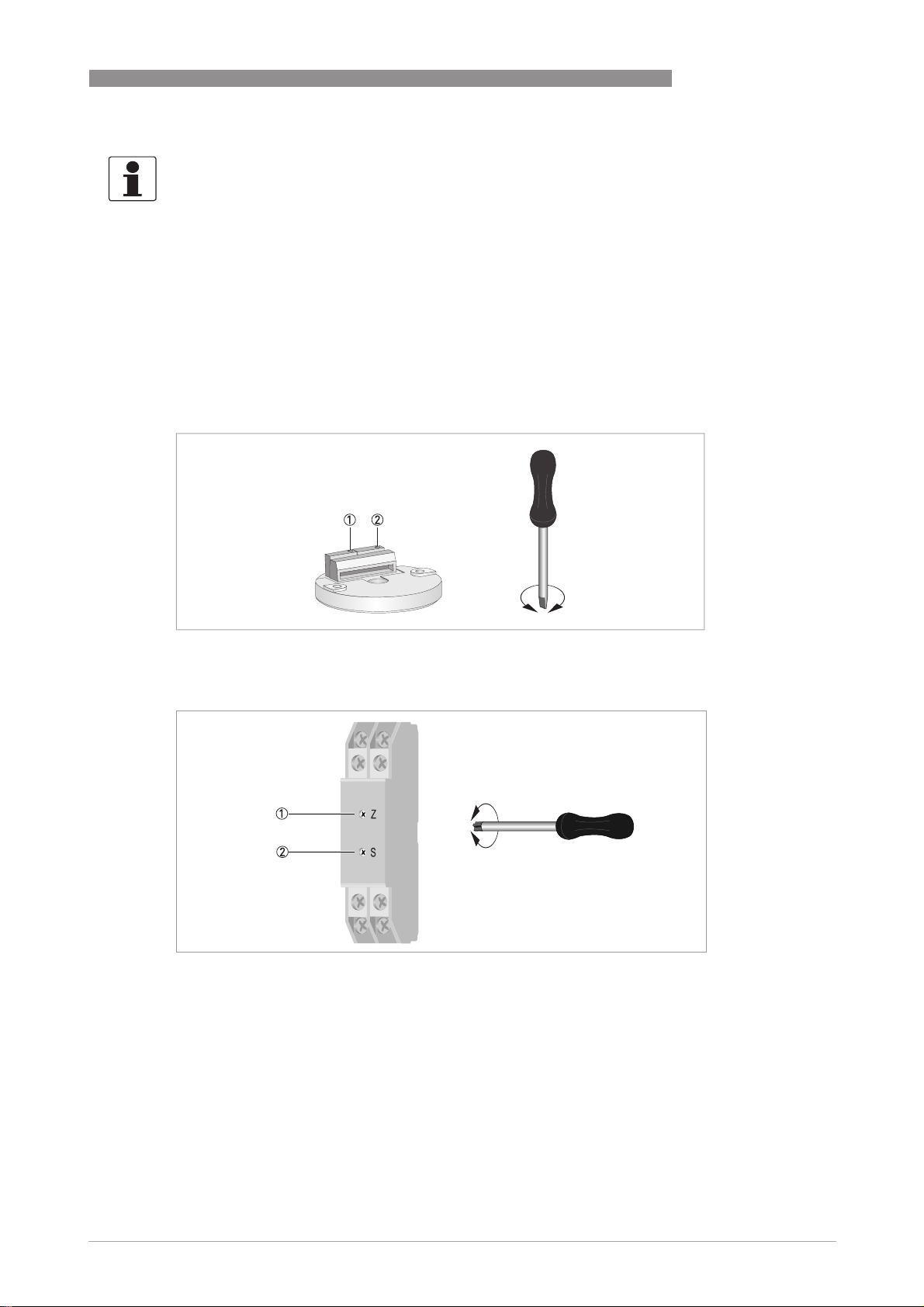
Potentiometers of the in-head version
OPERATION 5
1 Potentiometer for zero point setting
2 Potentiometer for measuring span setting
Potentiometers of the rail-mount version
1 Potentiometer for zero point setting
2 Potentiometer for measuring span setting
www.krohne.com05/2011 - 4000752902 - MA OPTITEMP TT 11 C/R R02 en
27
Page 28

5 OPERATION
INFORMATION!
The following calibration procedure is valid not only for the rail-mount transmitter, but also for
the in-head transmitter.
• Connect the power supply and the precision measuring device for current measurement
according to the connection diagram in the chapter "Electrical connections" (the typical power
supply is 24 VDC)..
• Connect the resistance decade according to the connection diagram in the chapter "Electrical
connections".
• Set an input signal that delivers an output signal of 5 V.
• Wait circa 15 minutes and check the stability of the output signal afterwards .Only if the output
signal is stable then, the transmitter is ready for calibration and you can go to the next step!
• Use the resistance decade to set an input signal T
measuring range value (e.g. 100 Ω for a measuring span from 0...+100°C / +32...212°F).
• Use the potentiometer for zero point setting to set exactly a voltage of U
drawing above).
• Use the resistance decade to set an input signal T
measuring range value (e.g. 138.5 Ω for a measuring span from 0...+100°C / +32...212°F).
• Use the potentiometer for the measuring span setting to set exactly a voltage of U
• Repeat the steps 5 till 8 until all of the signals are set exactly.
• Secure the potentiometers with varnish.
i The calibration is complete now.
OPTITEMP TT 11 C/R
that corresponds to the selected lower
in
= 0 V (refer to the
out
that corresponds to the selected upper
in
= 10 VDC.
out
28
www.krohne.com 05/2011 - 4000752902 - MA OPTITEMP TT 11 C/R R02 en
Page 29

OPTITEMP TT 11 C/R
6.1 Accessory parts
Accessory part Order code
Connection head installation kit VI70ADA00012
Rail mounting kit for in-head version VI70ADA00013
6.2 Spare parts availability
The manufacturer adheres to the basic principle that functionally adequate spare parts for each
device or each important accessory part will be kept available for a period of 3 years after
delivery of the last production run for the device.
This regulation only applies to spare parts which are subject to wear and tear under normal
operating conditions.
6.3 Availability of services
SERVICE 6
The manufacturer offers a range of services to support the customer after expiration of the
warranty. These include repair, maintenance, technical support and training.
INFORMATION!
For more precise information, please contact your local representative.
www.krohne.com05/2011 - 4000752902 - MA OPTITEMP TT 11 C/R R02 en
29
Page 30

6 SERVICE
6.4 Returning the device to the manufacturer
6.4.1 General information
This device has been carefully manufactured and tested. If installed and operated in accordance
with these operating instructions, it will rarely present any problems.
CAUTION!
Should you nevertheless need to return a device for inspection or repair, please pay strict
attention to the following points:
•
Due to statutory regulations on environmental protection and safeguarding the health and
safety of our personnel, manufacturer may only handle, test and repair returned devices that
have been in contact with products without risk to personnel and environment.
•
This means that the manufacturer can only service this device if it is accompanied by the
following certificate (see next section) confirming that the device is safe to handle.
CAUTION!
If the device has been operated with toxic, caustic, flammable or water-endangering products,
you are kindly requested:
•
to check and ensure, if necessary by rinsing or neutralizing, that all cavities are free from
such dangerous substances,
•
to enclose a certificate with the device confirming that is safe to handle and stating the
product used.
OPTITEMP TT 11 C/R
30
www.krohne.com 05/2011 - 4000752902 - MA OPTITEMP TT 11 C/R R02 en
Page 31

OPTITEMP TT 11 C/R
6.4.2 Form (for copying) to accompany a returned device
Company: Address:
Department: Name:
Tel. no.: Fax no.:
Manufacturer's order no. or serial no.:
The device has been operated with the following medium:
SERVICE 6
This medium is: water-hazardous
toxic
caustic
flammable
We checked that all cavities in the device are free from such
substances.
We have flushed out and neutralized all cavities in the
device.
We hereby confirm that there is no risk to persons or the environment through any residual media
contained in the device when it is returned.
Date: Signature:
Stamp:
6.5 Disposal
CAUTION!
Disposal must be carried out in accordance with legislation applicable in your country.
www.krohne.com05/2011 - 4000752902 - MA OPTITEMP TT 11 C/R R02 en
31
Page 32

7 TECHNICAL DATA
7.1 Resistance thermometer
The transmitter only works together with a measuring insert that has a Pt100 RTD. This kind of
measuring inserts features a temperature-sensitive sensor made from a platinum RTD, whose
value at 0°C / +32°F is 100 Ω. That is where the name "Pt100" comes from.
It is generally valid that the electric resistance of metals increases according to a mathematical
function as the temperature rises. This effect is taken advantage of by resistance thermometers
to measure temperature. The "Pt100" thermometer features a measuring resistance with
defined characteristics, standardised in IEC 60751. The same is true for the tolerances. The
average temperature coefficient of a Pt100 is 3.85 x 10
+32...+212°F.
During operation, a constant current I (≤ 1 mA) flows through the Pt100 RTD, which brings about
a voltage drop U. The resistance R is calculated using Ohm's Law (R=U/I). As the voltage drop U
at 0°C / +32°F is 100 mV, the resulting resistance of the Pt100 thermometer is 100 Ω (100 mV /
1 mA = 100 Ω).
OPTITEMP TT 11 C/R
-3K-1
in the range from 0...+100°C/
Figure 7-1: Pt100 resistance thermometer in 4 wire connection at 0°C / +32°F, schematic.
1 Pt100 RTD
2 Voltage meter
3 Current source
32
www.krohne.com 05/2011 - 4000752902 - MA OPTITEMP TT 11 C/R R02 en
Page 33

OPTITEMP TT 11 C/R
TECHNICAL DATA 7
7.2 Technical data
INFORMATION!
•
The following data is provided for general applications. If you require data that is more
relevant to your specific application, please contact us or your local representative.
•
Additional information (certificates, special tools, software,...) and complete product
documentation can be downloaded free of charge from the website (Download Center).
Measuring system
Application range Temperature measurements especially in building services applications.
Design
Versions
Versions
VersionsVersions
TT 11 C In-head transmitter which is optionally available in an intrinsically safe
TT 11 R Rail-mount transmitter, not available as intrinsically safe version.
Special feature
Special feature
Special featureSpecial feature
Sensor break monitoring User-definable output: ≤ 0V or>11VDC
version for installation in potentially explosive areas (zone 0).
Measuring accuracy
Accuracy Typically ± 0.15% of temperature span
Operating conditions
Temperature
Temperature
TemperatureTemperature
In-head transmitter Operating and storage temperature:
Rail-mount transmitter Operating and storage temperature:
Humidity 5...95% RH (non-condensing)
Protection category
Protection category
Protection categoryProtection category
In-head transmitter IP20 (with cover), IP10 (without cover)
Rail-mount transmitter IP20
Operating and storage temperature:
Operating and storage temperature:Operating and storage temperature:
-40...+85°C / -40...+185°F
Operating and storage temperature:
Operating and storage temperature:Operating and storage temperature:
-20...+70°C / -4...+158°F
www.krohne.com05/2011 - 4000752902 - MA OPTITEMP TT 11 C/R R02 en
33
Page 34

7 TECHNICAL DATA
OPTITEMP TT 11 C/R
Installation conditions
Mounting In-head transmitter: "B connection head" or larger according to DIN 43729;
Weight In-head transmitter : 40 g / 0.09 lb
Dimensions For detailed information refer to
with the help of the rail mounting kit you can also fix this transmitters on a
DIN rail according to DIN 50022 / EN 60715 ( refer to
head transmitters
Rail-mount transmitter: rail according to DIN 50022 / EN 60715, 35 mm /
1.38".
For detailed information refer to chapter "Installation".
Rail-mount transmitter: 55 g / 0.12 lb
on page 14).
Dimensions
on page 35.
Rail mounting kit for in-
Materials
Housing In-head transmitter: PC
Rail-mount transmitter: PC
Flammability acc. to UL V0 (all versions)
Electrical connections
Power supply
Power supply In-head transmitter: 15...30 VDC
Power supplyPower supply
Rail-mount transmitter: 15...30 VDC
Current consumption 12 mA
Galvanic isolation No
Connection
Polarity protection Standard for all versions
Single/stranded wires: max. 1.5 mm2/ AWG 16
Inputs / Outputs
Input
Input
InputInput
Type of connection: 3-wire
Span: 50/100/150/200°C and 100/200/300/400°F
Zero point: -50...+50°C / -60...+120°F
Fine adjustment: ±10%
Maximum lead resistance 11 Ω per wire
Output
Output
OutputOutput
Output signal 0...10 VDC, temperature linear, 3- or 4-wire connection
Update time ≤ 200 ms
Permissible load Min. 10 kΩ
NAMUR compliance Current limitations and failure currents acc. to NAMUR NE 21 (for
frequencies ≥ 150 kHz)
34
www.krohne.com 05/2011 - 4000752902 - MA OPTITEMP TT 11 C/R R02 en
Page 35

OPTITEMP TT 11 C/R
TECHNICAL DATA 7
Approvals and certifications
CE The device fulfils the statutory requirements of the EC directives.
Other standards and approvals
Other standards and approvals
Other standards and approvalsOther standards and approvals
Electromagnetic compatibility Directive: 2004/108/EC
The manufacturer certifies that these requirements have been met by
applying the CE marking.
Harmonized standard EN 61326-1:2006
7.3 Dimensions
In-head transmitter (Ex and Non-Ex)
Dimensions
[mm] [inches]
a 44 1.73
b 26 1.02
c 16 0.63
d 7 0.28
e 33 1.30
www.krohne.com05/2011 - 4000752902 - MA OPTITEMP TT 11 C/R R02 en
35
Page 36

7 TECHNICAL DATA
Rail-mount transmitter (Ex and Non-Ex)
OPTITEMP TT 11 C/R
Dimensions
[mm] [inches]
a 17.5 0.69
b 90 3.54
c 58 2.28
d 45 1.77
e 35 1.38
36
www.krohne.com 05/2011 - 4000752902 - MA OPTITEMP TT 11 C/R R02 en
Page 37

OPTITEMP TT 11 C/R
NOTES 8
www.krohne.com05/2011 - 4000752902 - MA OPTITEMP TT 11 C/R R02 en
37
Page 38

8 NOTES
OPTITEMP TT 11 C/R
38
www.krohne.com 05/2011 - 4000752902 - MA OPTITEMP TT 11 C/R R02 en
Page 39

OPTITEMP TT 11 C/R
NOTES 8
www.krohne.com05/2011 - 4000752902 - MA OPTITEMP TT 11 C/R R02 en
39
Page 40

KROHNE product overview
• Electromagnetic flowmeters
• Variable area flowmeters
• Ultrasonic flowmeters
• Mass flowmeters
• Vortex flowmeters
• Flow controllers
• Level meters
• Temperature meters
• Pressure meters
• Analysis products
• Measuring systems for the oil and gas industry
• Measuring systems for sea-going tankers
Head Office KROHNE Messtechnik GmbH
Ludwig-Krohne-Str. 5
D-47058 Duisburg (Germany)
Tel.:+49 (0)203 301 0
Fax:+49 (0)203 301 10389
info@krohne.de
© KROHNE 05/2011 - 4000752902 - MA OPTITEMP TT 11 C/R R02 en - Subject to change without notice.
The current list of all KROHNE contacts and addresses can be found at:
www.krohne.com
 Loading...