

Page 1
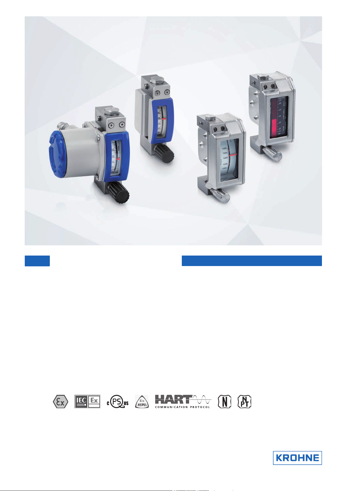
Technical Datasheet
Technical Datasheet
DK32 - DK34 - DK37
DK32 - DK34 - DK37
DK32 - DK34 - DK37DK32 - DK34 - DK37
Technical DatasheetTechnical Datasheet
Variable area flowmeters
•
Local measurement, setting and monitoring of very low flow rates
•
Compact design, no inlet and outlet sections
•
High resistance to pressure and temperature
© KROHNE 11/2018 - 4000282606 - TD DK32-34-37 R07 en
Page 2

CONTENTS
DK32 - DK34 - DK37
1 Product features 3
1.1 Variable area flowmeters in an all-metal design ............................................................ 3
1.2 Options for type DK metal ................................................................................................ 4
1.3 Functional principle.......................................................................................................... 6
2 Technical data 7
2.1 Technical data................................................................................................................... 7
2.2 Dimensions and weight .................................................................................................. 13
2.2.1 DK32, DK34 ........................................................................................................................... 13
2.2.2 DK32, DK34 with transmitter housing ESK3x ...................................................................... 15
2.2.3 DK37/M8M............................................................................................................................. 16
2.2.4 DK37/M8E.............................................................................................................................. 17
2.2.5 Minimum distances when installing several measuring devices ........................................ 18
2.3 Measuring ranges...........................................................................................................19
2.4 Differential pressure regulators .................................................................................... 21
3 Installation 24
3.1 Intended use ................................................................................................................... 24
3.2 Installation conditions ....................................................................................................25
4 Electrical connections 26
4.1 Electrical connection of the limit switches .................................................................... 26
4.2 Electrical signal output ESK3x for DK32, DK34............................................................. 27
4.2.1 Power supply......................................................................................................................... 28
4.2.2 Load for HART communication............................................................................................. 28
4.2.3 Configuration......................................................................................................................... 28
4.3 Settings of limit switches for DK37/M8M....................................................................... 29
4.4 Electrical signal output for DK37/M8E........................................................................... 30
4.4.1 Power supply......................................................................................................................... 31
4.4.2 Load for HART communication............................................................................................. 31
4.4.3 Configuration......................................................................................................................... 31
4.5 Grounding connections................................................................................................... 32
4.6 Ingress protection .......................................................................................................... 33
5 Order form 34
6 Notes 35
2
www.krohne.com 11/2018 - 4000282606 - TD DK32-34-37 R07 en
Page 3
DK32 - DK34 - DK37
PRODUCT FEATURES
1.1 Variable area flowmeters in an all-metal design
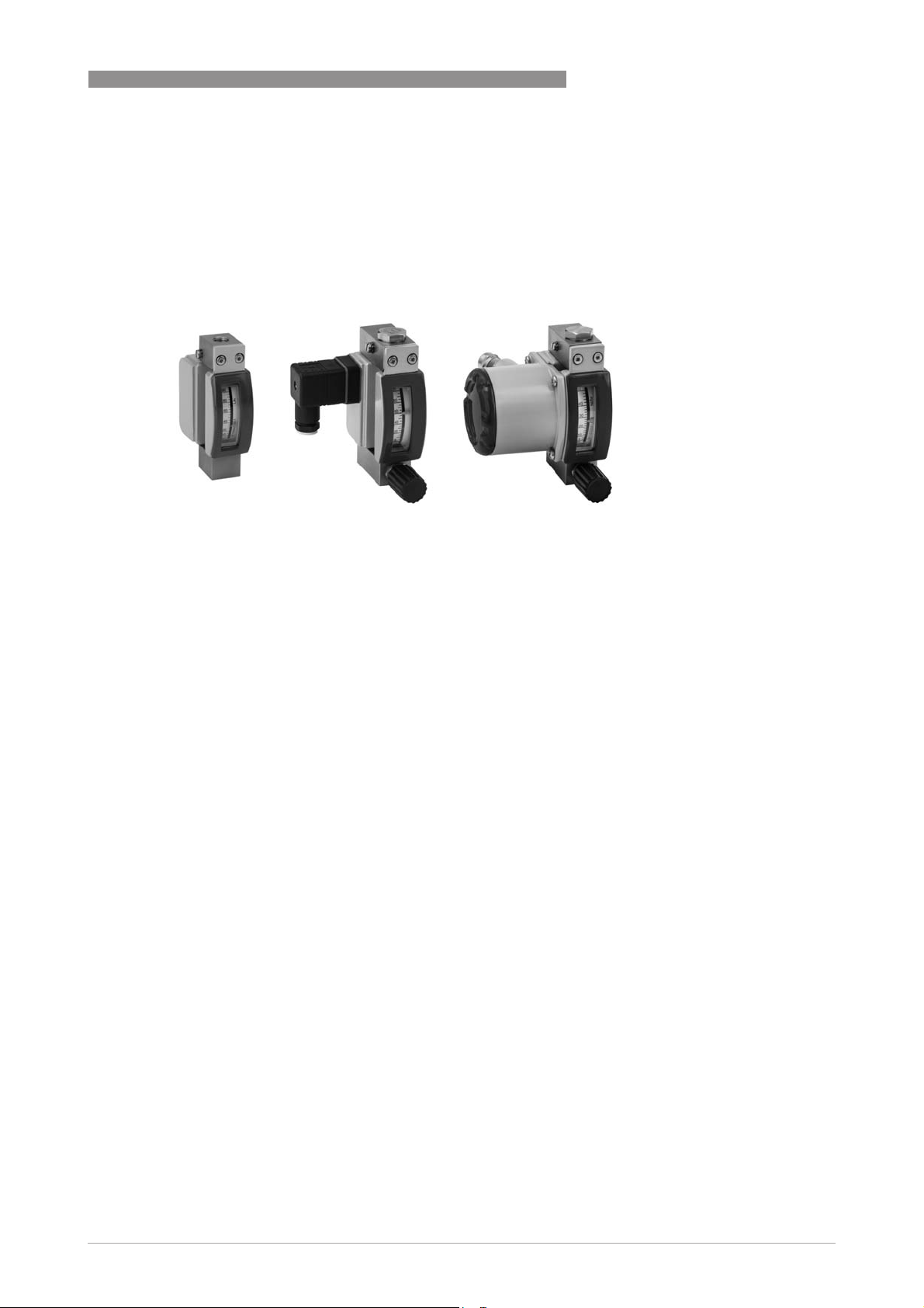
The solid metal DK flowmeters are suitable for measuring liquids and gases.
Because of their robust design the flowmeters are particularly suited for difficult operating and
environmental conditions.
The extremely compact design and the elimination of inlet and outlet sections allows for simple
and cost-effective integration into measuring systems such as process analysers.
1
Highlights
• DK32 with horizontal connections - with valve
• DK34 with vertical connections - without valve
• DK37 with a higher measuring accuracy and larger indication
• Narrow design enabling a high packing density
• Easy installation and commissioning
Industries
• Chemical
• Petrochemical
• Oil & Gas
• Mechanical and plant engineering
• Analyser system building
• Compressor and pump technology
Applications
The devices are particularly suitable for the measurement of small quantities of:
• Process or carrier gases
• Nitrogen, CO
• Sample flows for process analysers
• Sealing gas or sealing liquid measurement on sealing systems
• Purge fluids for measuring systems
• Air or water
• Chemicals and additives
• Lubricating, cooling and anti-corrosive agents
or other industrial gases
2
www.krohne.com11/2018 - 4000282606 - TD DK32-34-37 R07 en
3
Page 4
1
PRODUCT FEATURES
1.2 Options for type DK metal
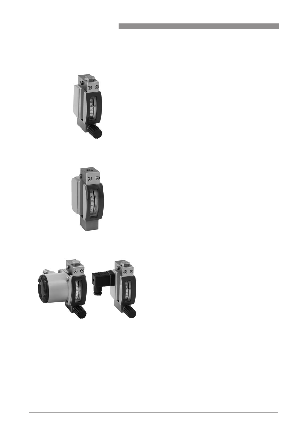
DK32
DK32
DK32DK32
DK34
DK34
DK34DK34
DK32 - DK34 - DK37
• Horizontal process connections, rear
• For flow rates of 0.15...150 l/h liquid or 1.6...4800 l/h
gas
• Design with valve at bottom, valve on top or without
valve
• Vertical process connections
• For flow rates of 0.15...150 l/h liquid or 1.6...4800 l/h
gas
• Design without valve
DK32, DK34 with electrical signal outputs
DK32, DK34 with electrical signal outputs
DK32, DK34 with electrical signal outputsDK32, DK34 with electrical signal outputs
Electrical options:
Electrical options:
Electrical options:Electrical options:
• 1 or 2 limit switches, NAMUR
• 1 limit switch, Reed
• 4...20 mA current output and HART
®
communication
4
www.krohne.com 11/2018 - 4000282606 - TD DK32-34-37 R07 en
Page 5
DK32 - DK34 - DK37
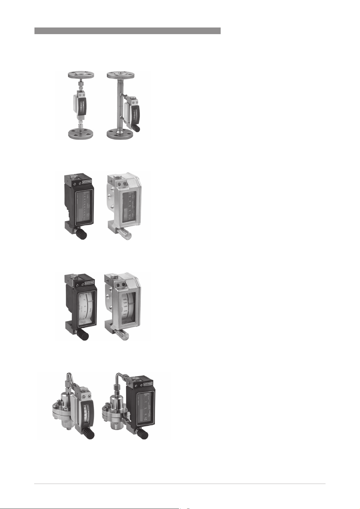
DK32, DK34 with flange connection adapter
DK32, DK34 with flange connection adapter
DK32, DK34 with flange connection adapterDK32, DK34 with flange connection adapter
DK37/M8E
DK37/M8E
DK37/M8EDK37/M8E
PRODUCT FEATURES
Flange connection adapters with a standard length of
250 mm / 9.8" and DN15/DN25 flanges can be used for
connection to the process instead of the NPT/G threads.
• Electronic bargraph indicator
• 4...20 mA current output and HART
• For flow rates of 0.15...250 l/h liquid or 1.6...8000 l/h
gas
• Design with valve at bottom, valve on top or without
valve
®
communication
1
DK37/M8M
DK37/M8M
DK37/M8MDK37/M8M
DK32, DK37 with flow regulator
DK32, DK37 with flow regulator
DK32, DK37 with flow regulatorDK32, DK37 with flow regulator
Standard housing M8E: PPS, conductive plastic
Optional housing M8E/R: stainless steel 1.4404/CF8M
• Max. two limit switches (NAMUR)
• For flow rates of 0.15...250 l/h liquid or 1.6...8000 l/h
gas
• Design with valve at bottom, valve on top or without
valve
Standard housing M8E: PPS, conductive plastic
Optional housing M8E/R: stainless steel 1.4404/CF8M
The inlet or outlet pressure regulators are used to
provide constant flow rates in the case of variable inlet
or outlet pressures.
www.krohne.com11/2018 - 4000282606 - TD DK32-34-37 R07 en
5
Page 6
1
PRODUCT FEATURES
1.3 Functional principle
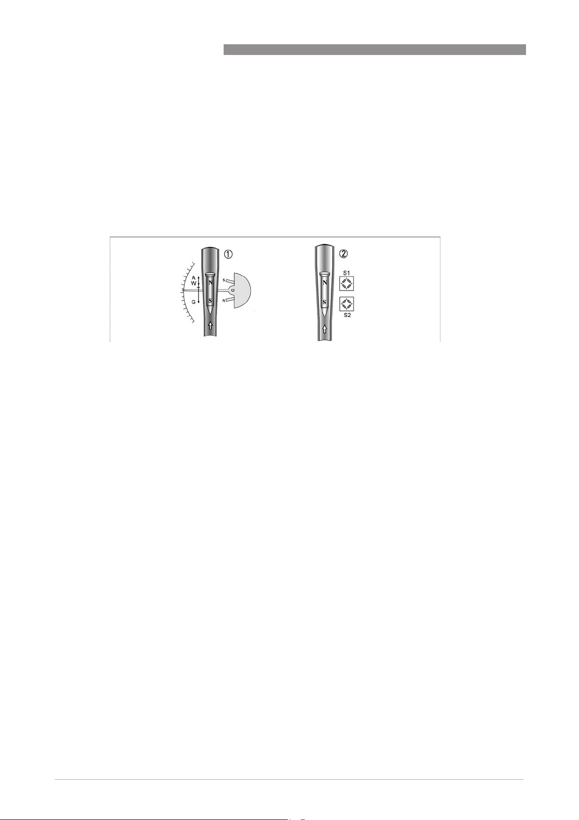
The flowmeter operates in accordance with the float measuring principle.
The measuring unit consists of a metal cone in which a float can move freely up and down.
The medium flows through the flowmeter from bottom to top.
The float adjusts itself so that the buoyancy force A acting on it, the form resistance W and its
weight G are in equilibrium: G = A + W
DK32 - DK34 - DK37
Figure 1-1: Functional principle
For DK32, DK34 and DK37/M8M 1 the flow-dependent height of the float in the measuring unit is
transmitted by means of a magnetic coupling on a scale.
For DK37/M8E, DK32/ESK and DK34/ESK 2 the flow-dependent height of the float in the
measuring unit is transmitted to the electronic display by means of a magnetic coupling on
sensors S1 and S2.
6
www.krohne.com 11/2018 - 4000282606 - TD DK32-34-37 R07 en
Page 7
DK32 - DK34 - DK37
2.1 Technical data
•
The following data is provided for general applications. If you require data that is more
relevant to your specific application, please contact us or your local sales office.
•
Additional information (certificates, special tools, software,...) and complete product
documentation can be downloaded free of charge from the website (Downloadcenter).
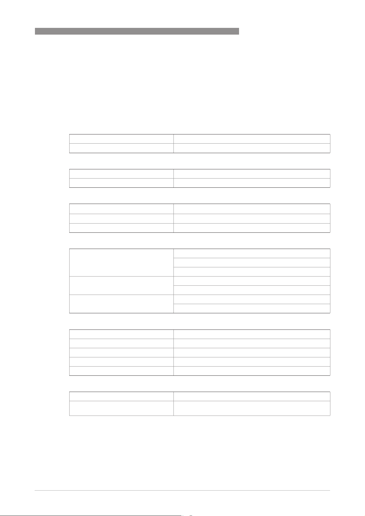
Measuring system
Application range Flow measurement of liquids or gases
Function / Measuring principle Float measuring principle
Measured value
Primary measured value Float position
Secondary measured value Operating volume flow, nominal volume flow or mass flow
Measuring accuracy
Directive VDI/VDE 3513, sheet 2 (qG = 50%)
DK32, DK34 4.0%
DK37 2.5%
TECHNICAL DATA
2
Operating conditions
Max. operating temperature TS Depending on the version (refer to nameplate)
Standard version: up to +150°C / +221°F
HT version: up to +200°C / +392°F
Max. operating pressure PS Depending on the version (refer to nameplate)
Standard version: 130 barg / 1885 psig
Max. test pressure PT Depending on the version (refer to nameplate)
Standard version: 202 barg / 2930 psig
1
1
Ingress protection
DK32, DK34 mechanical IP66/IP68
DK32, DK34 with limit switches K1/K2 IP65
DK32, DK34 with transmitter ESK3x IP66/IP68
DK37 with PPS indicator IP66
DK37 with stainless steel indicator IP66/IP67
Installation conditions
Inlet and outlet sections None
Protect devices from vibration and highfrequency oscillation
1 Higher pressures on request
Use in accordance with IEC 61298-3 in control room or field
with medium vibration level
www.krohne.com11/2018 - 4000282606 - TD DK32-34-37 R07 en
7
Page 8
2
TECHNICAL DATA
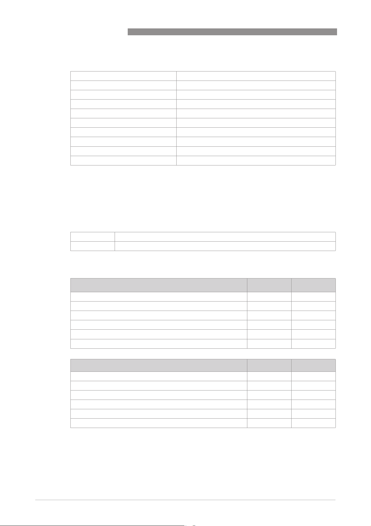
Materials
Top fitting, bottom fitting, cone CrNi steel 1.4404 / 316 L
Lock screw CrNi steel 1.4404 / 316 L
Float, standard CrNi steel 1.4404 / 316 L or titanium
Dosing unit CrNi steel 1.4571 / 316 Ti
Valve stem CrNi steel 1.4404 / 316 L
Gasket of lock screw PTFE
Gasket of dosing unit FPM/PTFE, PTFE, FFKM
Indicator housing of DK32, DK34 Die-cast aluminium with powder coating
Indicator housing of DK37/M8_/ PPS
Indicator housing of DK37/M8_/R/ Stainless steel 1.4408/CF8M
1 Other gasket materials on request
Other options on request:
• Surface passivation of all metallic, wetted parts
• Special materials: e.g. Hastelloy
1
®
, Monel®, Inconel®, titanium a.o.
DK32 - DK34 - DK37
Process connection
Standard 1/4 NPT (female)
Option G1/4, Ermeto, Serto, Gyrolok, Swagelok, flanges
1 Other connections on request
1
Temperatures
Max. product temperature at T
DK34, DK32, DK37 without valve -80…+150 -112...+302
DK32, DK37 with valve FPM/PTFE -25…+150 -13...+302
DK32, DK37 with valve FFKM -20…+150 -4...+302
DK32, DK37 with valve PTFE -40…+150 -40...+302
DK32 HT, DK34 HT high-temperature with FFKM -20…+200 -4...+392
DK32, DK34 with transmitter ESK3x -40...+140 -40...+284
Permissible ambient temperature 1 [°C] [°F]
DK32, DK34, DK37/M8M without electrical built-ins -40…+70 -40...+158
DK32, DK34, DK37/M8M with limit switch I7S2002-N or SJ2-SN -40…+70 -40...+158
DK32, DK34, DK37/M8M with limit switch SC2-N0 -25…+70 -13...+158
DK32, DK34 with transmitter ESK3x -40…+70 -40...+158
DK37/M8E -40…+70 -40...+158
DK32 HT, DK34 HT high-temperature -25…+200 -13...+392
< +40°C / +104°F 1 [°C] [°F]
amb.
1 For restrictions in hazardous areas refer to the temperature tables in the supplementary Ex
instructions
8
www.krohne.com 11/2018 - 4000282606 - TD DK32-34-37 R07 en
Page 9
DK32 - DK34 - DK37
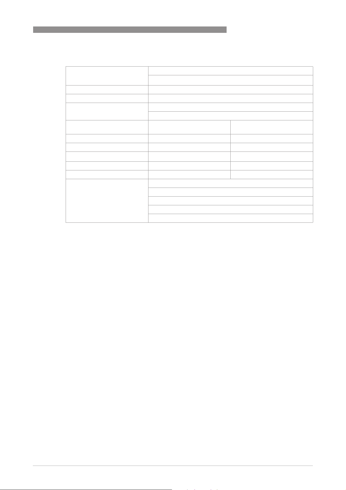
Indicator DK32, DK34, DK37/M8M with limit switch
TECHNICAL DATA
2
DK32 - 34 /K./S
DK37/M8M
DK32 - 34 /K./S Clamping range: 4.5...10 mm / 0.18...0.4"
DK37/M8M Clamping range: 3...7 mm / 0.12...0.28"
DK32 - 34/K./L Ø Connecting cable: 6.3 mm / 0.25"; 0.75 mm²
Limit switches SC2-N0
Connection type NAMUR 2-wire 2-wire
Switching element function Normally closed Normally closed
Nominal voltage U
Pointer vane not detected ≥ 3mA ≥ 3mA
Pointer vane detected ≤1mA ≤1mA
DK32 - DK34 with Reed contact Type: SPDT (3-wire, normally closed and normally open)
1 Reduced values for Ex
0
Cable gland: M16 x 1.5
1
2
SJ2-SN (safety-oriented)
SJ2-SN (safety-oriented)
SJ2-SN (safety-oriented)SJ2-SN (safety-oriented)
1
1
Terminal connection: 1.5 mm
Cable length: approx. 1.7 m / 5.6 ft (other lengths on request)
SC2-N0
SC2-N0SC2-N0
I7S2002-N
I7S2002-N
I7S2002-NI7S2002-N
8VDC 8VDC
Switching reproducibility: < 5% of full scale range
Switching capacity: 12 VA
Max. switching capacity: 30 VDC
Max. switching current: 0.5 A
www.krohne.com11/2018 - 4000282606 - TD DK32-34-37 R07 en
9
Page 10
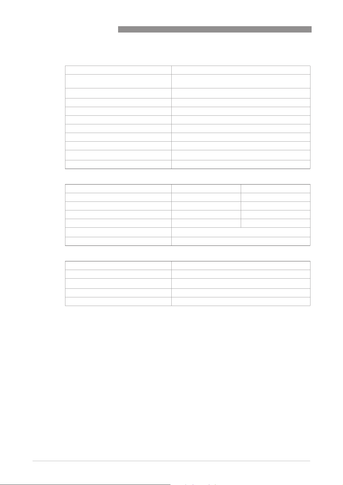
2
TECHNICAL DATA
Transmitter ESK3x for DK32, DK34
Cable entry M16 x 1.5 or 1/2" NPT
Clamping range of cable gland 3...7 mm / 0.12...0.28" (PA gland) or 5...10 mm / 0.2...0.39"
Terminal connection
Measuring signal 4...20 mA = 0…100% flow value in 2-wire technology
Power supply 12...32 VDC (non-Ex)
Power supply influence < 0.1%
Dependence on load impedance < 0.1%
Temperature influence <0.3%/10 K
Max. external resistance / load 500 Ω (24 VDC), 800 Ω (32 VDC)
Min. load for HART
NAMUR type test acc. to NE 95 Fulfills NE 21, NE 43, NE 107
ESK3x - electrical characteristics
Process variable flow rate Values [%]
Upper range limit +103.125 20.5
Device error identification < -2.5 or >106.25 <3.6 or > 21
Maximum 118.75 23.0
Multi-Drop operation - 4.0
Min. U
ext.
Capacitance number (CN) 2
DK32 - DK34 - DK37
(stainless steel gland)
2
1.5 mm
®
250 Ω
Values [%] Signal output [mA]
Values [%]Values [%]
12 VDC
Signal output [mA]
Signal output [mA]Signal output [mA]
ESK3x HART Device
Manufacturer name (code) KROHNE Messtechnik (0x0045)
Model name ESK3x (0x45BA)
HART® protocol
Device revision 1
Equipment category Transmitter
Revision 7.6
10
www.krohne.com 11/2018 - 4000282606 - TD DK32-34-37 R07 en
Page 11
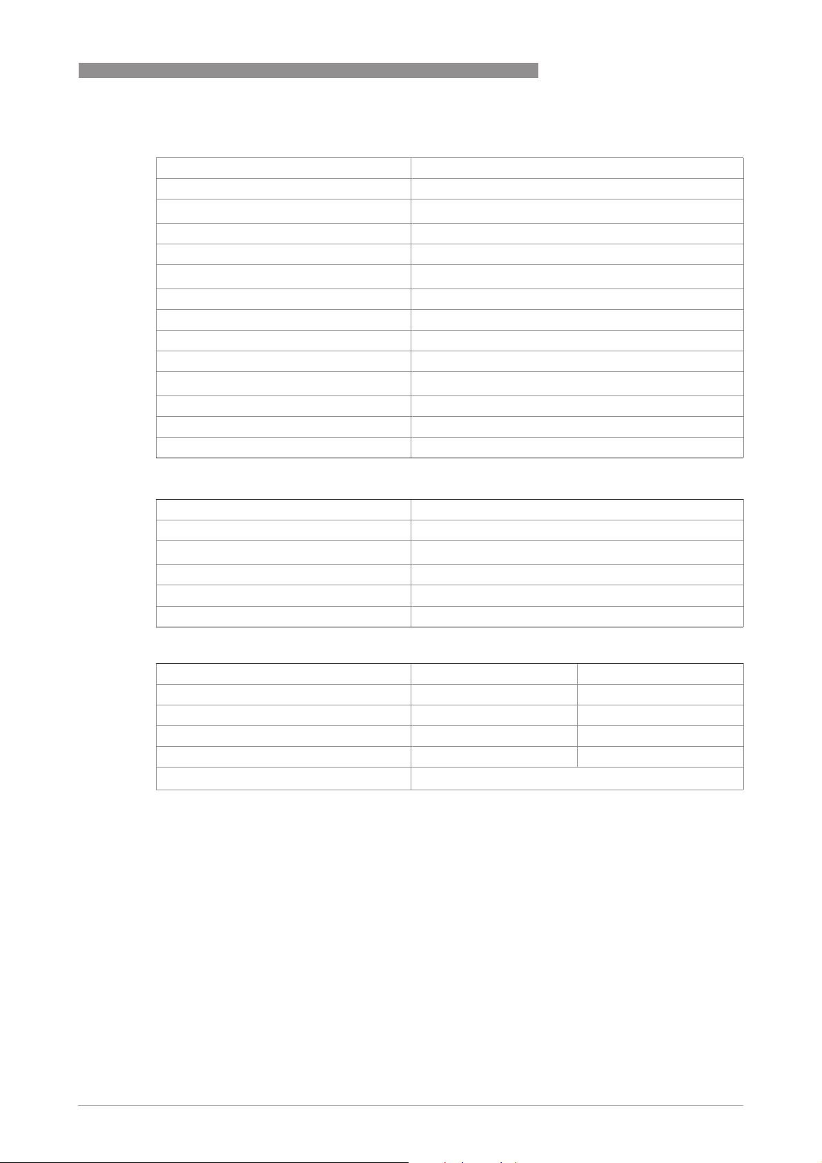
DK32 - DK34 - DK37
Indicator DK37/M8E
Cable gland M16 x 1.5
Clamping range 3...7 mm / 0.12...0.28"
Terminal connection
Measuring signal 4...20 mA = 0…100% flow value in 2-wire technology
Power supply 14.8...30 VDC
Min. power supply for HART
Power supply influence <0.1%
Dependence on load impedance <0.1%
Temperature influence <10 µA/K
Max. external resistance / load 640 Ω (30 VDC)
Min. load for HART
Software firmware version 01.15
Identification number 3204090400
NAMUR type test acc. to NE 95 Fulfills NE 21, NE 43
TECHNICAL DATA
2
2.5 mm
®
®
20.5 VDC
250 Ω
2
M8E HART® configuration
Manufacturer name (code) KROHNE Messtechnik (69)
Model name M8E (230)
HART® protocol
Device revision 1
Physical Layer FSK
Equipment category Transmitter
Revision 5.1
M8E process variable
Process variable flow rate Values [%]
Upper range limit +102.5 (±1%) 20.24...20.56
Device error identification >106.25 ≥21.00
Maximum 112.5 22
Multi-Drop operation - 4.5
Min. U
ext.
Values [%] Signal output [mA]
Values [%]Values [%]
14.8 VDC
Signal output [mA]
Signal output [mA]Signal output [mA]
www.krohne.com11/2018 - 4000282606 - TD DK32-34-37 R07 en
11
Page 12

2
TECHNICAL DATA
Approvals for DK32, DK34
Standard Device version Marking
DK32 - DK34 - DK37
ATEX Mechanical, without electrical built-ins II2G Ex h IIC T6...T3 Gb
NAMUR limit switch K1/K2 II2G Ex ia IIC T6 Gb
Reed limit switch R1 II2G Ex ia IIC T6 Gb
4...20 mA / HART signal output ESK3x II2G Ex d IIC T6 Gb
IECEx NAMUR limit switch K1/K2 Ex ia IIC T6 Gb
Reed limit switch R1 Ex ia IIC T6 Gb
4...20 mA / HART signal output ESK3x Ex d IIC T6 Gb
FM (US) NAMUR limit switch K1/K2 IS/I/1/ABCD; T6
Reed limit switch R1 IS/I/1/ABCD; T6
QPS (US/C)
(pending)
Other approvals as NEPSI, INMETRO, KCS, CCOE, EAC on request.
4...20 mA / HART signal output ESK3x XP/I/1/ABCD; T6
II2D Ex h IIIC T150°C Db
II2D Ex ia IIIC T75°C Db
II3G Ex nA/ec IIC T6 Gc
II2G Ex ia IIC T6 Gb
II2D Ex ia IIIC T75°C Db
II3G Ex nA/ec IIC T6 Gc
II2D Ex tb IIIC 75° Db
Ex ia IIIC T75°C Db
Ex nA/ec IIC T6 Gc
Ex ia IIC T6 Gb
Ex ia IIIC T75°C Db
Ex nA/ec IIC T6 Gc
Ex tb IIIC 75° Db
NI/I/2/ABCD; T6
IS/I/1/ABCD; T6
NI/I/2/ABCD; T6
DIP/II,III/1EFG;T6
Approvals for DK37
Standard Device version Marking
ATEX Mechanical, without electrical built-ins II2G Ex h IIC T6...T3 Gb
Electrical II2G Ex ia IIC T6 Gb
IECEx Electrical Ex ia IIC T6 Gb
QPS (US/C) Electrical IS/I/1/ABCD; T6
Other approvals as NEPSI, INMETRO, KCS, CCOE, EAC on request.
II2D Ex h IIIC T150°C Db
II2D Ex ia IIIC T75°C Db
Ex ia IIIC T75°C Db
12
www.krohne.com 11/2018 - 4000282606 - TD DK32-34-37 R07 en
Page 13

DK32 - DK34 - DK37
2.2 Dimensions and weight
2.2.1 DK32, DK34
TECHNICAL DATA
2
DK32 with top/bottom valve and rear process
connection
1 2
Dimensions Weight
a b c d
[mm] ["] [mm] ["] [mm] ["] [mm] ["] g lb
1 DK32 42 1.66 118 4.65 90 3.55 100 3.94 700 1.54
2 DK34 42 1.66 110 4.33 - - 75 3.07 600 1.32
Version with limit switch with connector Version with limit switch with cable end
DK32 with bottom valve /
DK34 without valve
DK32 with top valve DK32 with bottom
DK34 without valve and vertical process
connection
approx.
DK32 with top valve
valve /
DK34 without valve
3
Dimensions Weight
a b c d
[mm] ["] [mm] ["] [mm] ["] [mm] ["] g lb
3 DK32 46 1.81 approx. 90approx.
DK34 600 1.32
Weight for DK32 with differential pressure regulator: 2500 g / 5.51 lb
3.55
www.krohne.com11/2018 - 4000282606 - TD DK32-34-37 R07 en
1500 59 approx. 50approx.
1.97
approx.
700 1.54
13
Page 14
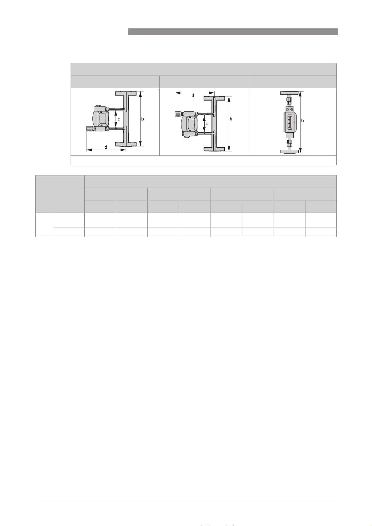
2
TECHNICAL DATA
Version with flange adapter
DK32 with bottom valve DK32 with top valve DK34 without valve
[mm] ["] [mm] ["] [mm] ["] [mm] ["]
DK32 - DK34 - DK37
4
Dimensions
a b c d
4 DK32 - - 250 10.2 90 3.55 approx.
195
DK34 - - 250 10.2 - - - -
Extra weight for flange adapter dependent on pressure rating of flange: approx. 1.5...9 kg /
3.3...19.8 lb
approx.
7.68
14
www.krohne.com 11/2018 - 4000282606 - TD DK32-34-37 R07 en
Page 15
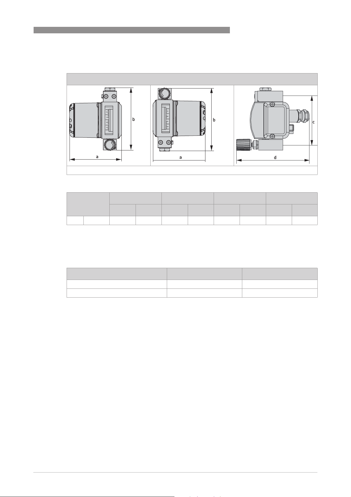
DK32 - DK34 - DK37
2.2.2 DK32, DK34 with transmitter housing ESK3x
DK32 with ESK transmitter housing with top/bottom valve
Dimensions
a b c d
1
TECHNICAL DATA
2
[mm] ["] [mm] ["] [mm] ["] [mm] ["]
1 DK32 100 3.94 118 4.65 90 3.55 140 5.51
Total length of flange connection adapter:
DK32/ESK with top or bottom valve: 250 mm / 9.8"
Weights
approx. g approx. lb
DK32 with transmitter ESK3x 1100 2.43
DK34 with transmitter ESK3x 1000 2.21
www.krohne.com11/2018 - 4000282606 - TD DK32-34-37 R07 en
15
Page 16

2
TECHNICAL DATA
2.2.3 DK37/M8M
DK32 - DK34 - DK37
With bottom valve and rear process
connection
With top valve and rear process
connection
1 2
Without valve and vertical
process connection
Dimensions
a b c d
[mm] ["] [mm] ["] [mm] ["] [mm] ["]
1 With valve 56 2.21 153 6.03 125 4.92 approx.
2 Without valve 56 2.21 145 5.71 145 5.71 approx.
144
144
Total length of flange connection adapter:
DK37/M8M with top/bottom valve: 250 mm / 9.8"
approx.
5.67
approx.
5.52
Weights
approx. g approx. lb
DK37/M8M 800 1.76
DK37/M8M with differential pressure
regulator
DK37/M8M/R 2100 4.63
DK37/M8M/R with differential pressure
regulator
2600 5.73
3900 8.60
16
www.krohne.com 11/2018 - 4000282606 - TD DK32-34-37 R07 en
Page 17

DK32 - DK34 - DK37
2.2.4 DK37/M8E
TECHNICAL DATA
2
With bottom valve and rear process
connection
1 2 3
With top valve and rear process
connection
Without valve and vertical
process connection
Dimensions
a b c d
[mm] ["] [mm] ["] [mm] ["] [mm] ["]
1 With bottom valve 56 2.21 153 6.03 125 4.92 approx.
2 With top valve 56 2.21 183 7.21 155 6.11 approx.
3 Without valve 56 2.21 145 5.71 145 5.71 approx.
144
144
121
approx.
5.67
approx.
5.67
approx.
4.77
Total length of flange connection adapter:
DK37/M8E with bottom valve: 250 mm / 9.8"
DK37/M8E with top valve: 300 mm / 11.8"
Weights
approx. g approx. lb
DK37/M8E 1000 2.21
DK37/M8E with differential pressure
regulator
DK37/M8E/R 2300 5.07
DK37/M8E/R with differential pressure
regulator
2800 6.18
4100 9.04
www.krohne.com11/2018 - 4000282606 - TD DK32-34-37 R07 en
17
Page 18
2
TECHNICAL DATA
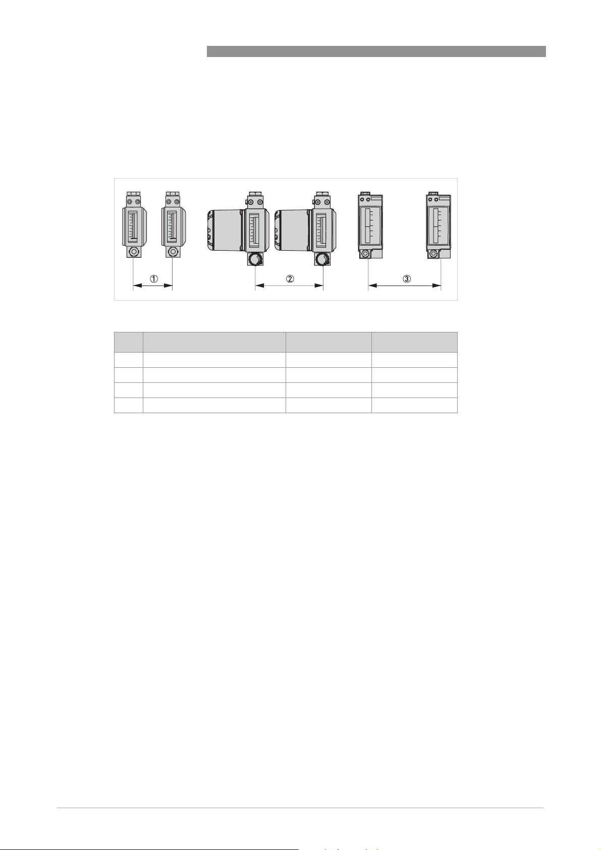
2.2.5 Minimum distances when installing several measuring devices
When installing several measuring devices side by side, a minimum distance between them has
to be observed.
Figure 2-1: Minimum distances when installing several measuring devices
Device [mm] ["]
DK32 - DK34 - DK37
1 DK32, DK34 60 2.36
2 DK32/ESK, DK34/ESK 140 5.51
3 DK37/M8M 100 3.94
3 DK37/M8E 120 4.73
18
www.krohne.com 11/2018 - 4000282606 - TD DK32-34-37 R07 en
Page 19
DK32 - DK34 - DK37
TECHNICAL DATA
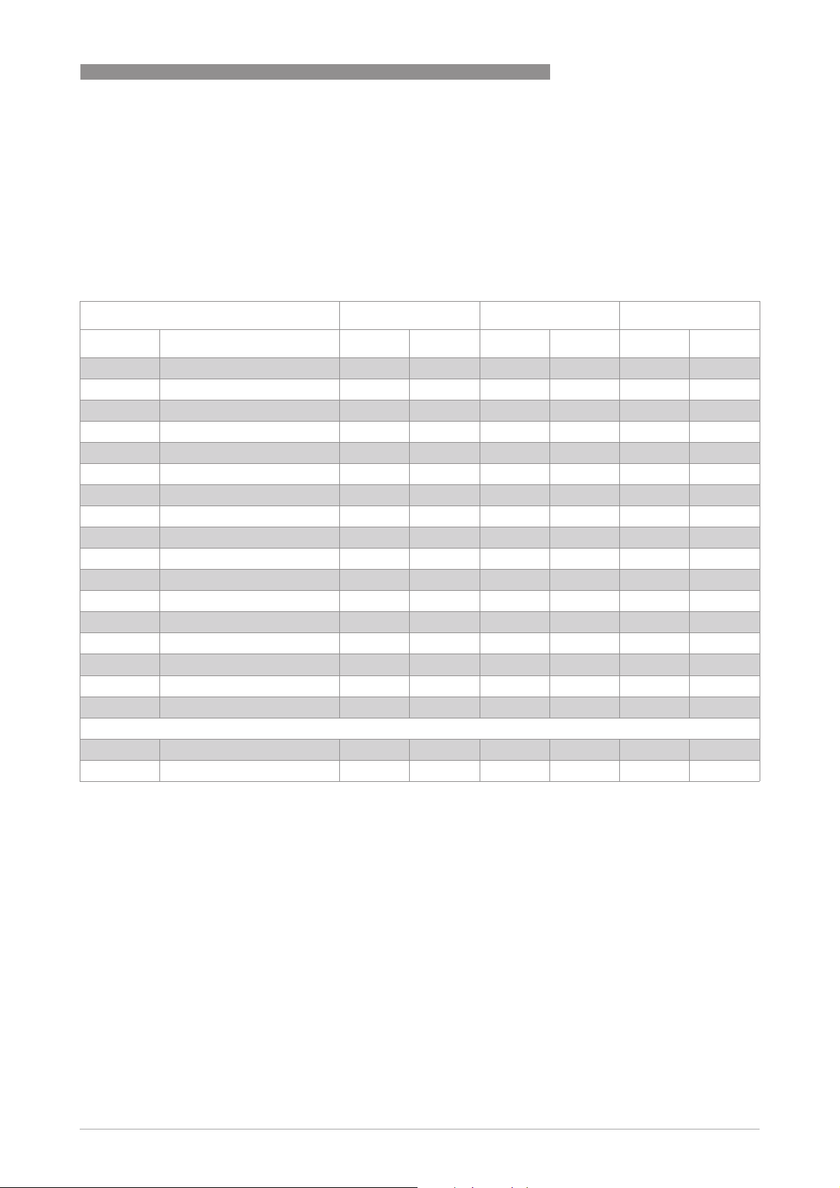
2.3 Measuring ranges
Measuring span: 10 : 1
Flow values: Values = 100%
Water: +20°C / +68°F
Air: +20°C / +68°F, 1.013 bara / 14.7 psia
Flow, water Flow, air Pressure loss
Cones Float [l/h] [GPH] [Nl/h] [SCFH] [mbar] [psi]
2
K 005 N3 titanium
K 005 N1 titanium
K 005 N1 Stainless steel - - 50 2 31 0.45
K 010 N1 titanium
K 010 N1 Stainless steel 3 0.8 100 4 38 0.55
K 015 N1 titanium
K 015 N1 Stainless steel 5 1.3 150 6 19 0.28
K 040 N2 titanium
K 040 N2 Stainless steel 10 2.6 400 15 27 0.39
K 080 N2 titanium
K 080 N2 Stainless steel 25 6.6 800 30 55 0.8
K 125 N2 titanium
K 125 N2 Stainless steel 40 11 1250 50 42 0.61
K 200 N2 Stainless steel 60 16 2000 75 85 1.23
K 300 N2 Stainless steel 80 21 2500 100 117 1.7
K 340 N2 Stainless steel 100 26 3400 125 166 2.4
K 340 N2 Triamet 150 40 4800 180 210 3.01
K 340
2
K 340
2
1 Titanium components are not suitable for use in oxygen applications (media with an oxygen content that is significantly higher than the
oxygen content in the earth's atmosphere)!
2 DK37 only
Special Stainless steel 200 53 6000 225 462 6.7
Special Triamet 250 66 8000 300 722 10.5
1
1
1
1
1
1
1
- - 16 0.6 17 0.25
- - 25 1
1.5 0.4 70 2.6 31 0.45
3 0.8 100 4 17 0.25
7 1.8 250 10 17 0.25
16 4.2 550 20 32 0.47
25 6.6 - - 45 0.65
The operating pressure should be at least double the pressure loss for liquids and five times for
gases. The indicated pressure losses are valid for water and air at maximum flow rate. Other
flow ranges on request. Conversion of other media or operating data is performed using the
calculation method in accordance with VDI/VDE directive 3513.
Reference condition for gas measurements:
Reference condition for gas measurements:
Reference condition for gas measurements:Reference condition for gas measurements:
Flow measurements for gases are attributed to:
3
- Nl/h or Nm
/h: Volume flow at standard (norm.) conditions 0°C / +32°F, 1.013 bara / 14.7 psia
(DIN 1343)
- SCFM or SCFH: Volume flow at standard (std.) conditions +15°C / +59°F, 1.013 bara / 14.7 psia
(ISO 13443)
www.krohne.com11/2018 - 4000282606 - TD DK32-34-37 R07 en
19
Page 20

2
TECHNICAL DATA
DK32 - DK34 - DK37
Valves
Measuring span: 10 : 1
Flow values: Values = 100%
Water: +20°C / +68°F
Air: +20°C / +68°F, 1.013 bara / 14.7 psia
Only DK32 and DK37 Max. flow Qv Valve
characteristic
value
Valve stem Water Air Kv Cv
Cones Ø [mm] Ø ["] [l/h] [GPH] [Nl/h] [SCFH]
K 005 - K 010 1 0.039 5 1.32 100 3.72 0.018 0.021
K 015 - K 040 - K 080 2.5 0.98 50 13.2 1000 37.2 0.15 0.175
K 125 - K 340 4.5 0.177 160 42.3 4300 160 0.48 0.552
[m3/h]
[GPM]
Valve characteristics
Spindle 1.0 mm / 0.039" Spindle 2.5 mm / 0.098"
20
Spindle 4.5 mm / 0.177" 1 Flow, air
2 Flow, water
3 Spindle revolution n
www.krohne.com 11/2018 - 4000282606 - TD DK32-34-37 R07 en
Page 21
DK32 - DK34 - DK37
2.4 Differential pressure regulators
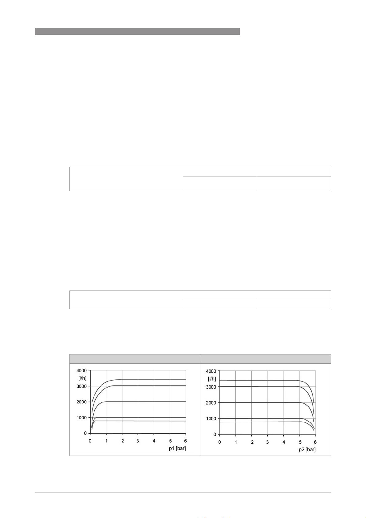
Differential pressure regulators are used (only DK32 and DK37) to guarantee constant flow
during fluctuating inlet and outlet pressure. Minimum pressures are required to operate the
regulators (refer to regulator characteristics).
Differential pressure regulators are not equivalent to pressure reducing valves!
1 Inlet pressure regulators, type RE, NRE
The regulators keep the flow rate constant in the case of a variable inlet pressure and a constant
outlet pressure.
TECHNICAL DATA
2
Example of inlet pressure regulator
RE-1000
The flow rate in the device remains constant with a fluctuating inlet pressure greater than
0.5 bar / 7.25 psi.
Current flow rate: 1000 l/h air
Outlet pressure p2
constant:
1.013 bara / 14.7 psia
2 Outlet pressure regulator, type RA, NRA
The regulators keep the flow rate constant in the case of a constant inlet pressure and a variable
outlet pressure.
There must be a pressure differential between the inlet and the outlet pressure for the outlet
pressure regulators to function. The inlet pressure p1 must always be greater than the outlet
pressure p2.
Example for outlet pressure regulator
NRA-800
The flow rate in the device remains constant with a fluctuating outlet pressure greater than
0...5.5 bar / 0...79.8 psi.
Current flow rate: 800 l/h air
Inlet pressure p1 constant: 6bar/ 87psi
Regulator characteristics
1 Inlet pressure regulators, type RE and NRE 2 Outlet pressure regulators, type RA and NRA
www.krohne.com11/2018 - 4000282606 - TD DK32-34-37 R07 en
21
Page 22
2
TECHNICAL DATA
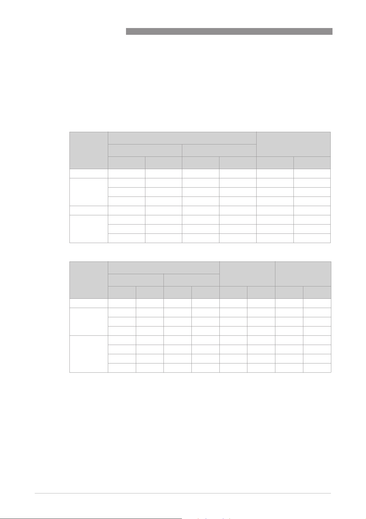
Control ranges
Measuring span: 10 : 1
Flow values: Values = 100%
Inlet pressure regulator 1
RE-1000 ...40 ...11 ...1000 ...37 0.5 7.25
RE-4000 ...80 ...20 ...2000 ...75 1 14.5
NRE-100 ...2.5 ...0.6 ...100 ...3.7 0.1 1.45
NRE-800 - - …250 ...9.0 0.1 1.45
DK32 - DK34 - DK37
Water: +20°C/ +68°F
Air: +20°C / +68°F, 1.013 bara / 14.7 psia
Max. flow rate Min. inlet pressure
Water Air
[l/h] [GPH] [Nl/h] [SCFH] p1 [bar] p1 [psi]
...100 ...25 …3000 ...110 1.5 21.8
...160 ...42 ...4000 ...150 2 29
- - …800 ...30 0.2 2.9
...25 ...6.6 - - 0.4 5.8
Outlet pressure regulator 2
Max. flow rate Min. inlet pressure Min. pressure diff.
Water Air
[l/h] [GPH] [Nl/h] [SCFH] p1 [bar] p1 [psi] Δp [bar] Δp [psi]
RA-1000 ...40 ...11 ...1000 ...37 0.5 7.25 0.4 5.8
RA-4000 ...100 ...25 …2000 ...75 1.5 21.8 1.2 17.4
- - ...3000 ...110 1.5 21.8 1.2 17.4
...160 ...42 ...4000 ...150 2 29 1.5 21.8
NRA-800 ...1 ...0.25 ...250 ...9.0 0.1 1.45 0.05 0.73
- - ...500 ...19 0.2 2.9 0.1 1.45
- - …800 ...30 0.4 5.8 0.2 2.9
...25 ...6.6 - - 0.4 5.8 0.4 5.8
* Differential pressure between inlet and outlet pressure
Reference condition for gas measurements:
Reference condition for gas measurements:
Reference condition for gas measurements:Reference condition for gas measurements:
Flow measurements for gases are attributed to:
3
- Nl/h or Nm
/h: Volume flow at standard (norm.) conditions 0°C / +32°F, 1.013 bara / 14.7 psia
(DIN 1343)
- SCFM or SCFH: Volume flow at standard (std.) conditions +15°C / +59°F, 1.013 bara / 14.7 psia
(ISO 13443)
*
22
www.krohne.com 11/2018 - 4000282606 - TD DK32-34-37 R07 en
Page 23

DK32 - DK34 - DK37
TECHNICAL DATA
Technical data for differential pressure regulator
Connection, standard 1/4 NPT
Connection, option Serto, Ermeto 6 or 8, hose nozzle 6 mm or 8 mm, Dilo, Gyrolok,
Max. operating gauge pressure (at +20°C / +68°F) 64 barg / 928 psig
Product temperature +150°C / +302°F
Material CrNi steel 1.4404
Gasket PTFE
Diaphragm Carbon/graphite-filled PTFE
O-ring FPM or FFKM
Swagelok, G1/4
Higher pressures and temperatures, other connections or materials on request
Dimensions with differential pressure regulator
approx. a approx. b c d
[mm] ["] [mm] ["] [mm] ["] [mm] ["]
DK32 230 9.1 163 6.4 70 2.8 23 0.91
DK37 230 9.1 200 7.9 70 2.8 23 0.91
DK37/M8E
1 with outlet pressure regulator
1
230 9.1 230 9.1 70 2.8 23 0.91
2
DK32 with inlet pressure regulator DK37/M8M and M8E with inlet pressure regulator
DK32 with outlet pressure regulator DK37/M8E with outlet pressure regulator
www.krohne.com11/2018 - 4000282606 - TD DK32-34-37 R07 en
23
Page 24

3
INSTALLATION
3.1 Intended use
Responsibility for the use of the measuring devices with regard to suitability, intended use and
corrosion resistance of the used materials against the measured fluid lies solely with the
operator.
This device is a Group 1, Class A device as specified within CISPR11:2009. It is intended for use in
industrial environment. There may be potential difficulties in ensuring electromagnetic
compatibility in other environments, due to conducted as well as radiated disturbances.
The manufacturer is not liable for any damage resulting from improper use or use for other than
the intended purpose.
The variable area flowmeters are suitable for measuring gases and liquids.
The devices are particularly suitable for the measurement of small quantities of:
• Process or carrier gases
• Nitrogen, CO
• Sample flows for process analysers
• Sealing gas or sealing liquid measurement on sealing systems
• Purge fluids for measuring systems
• Air or water
• Chemicals and additives
• Lubricating, cooling and anti-corrosive agents
or other industrial gases
2
DK32 - DK34 - DK37
For devices used in hazardous areas, additional safety notes apply; please refer to the Ex
documentation.
Do not use any abrasive media containing solid particles.
24
www.krohne.com 11/2018 - 4000282606 - TD DK32-34-37 R07 en
Page 25

DK32 - DK34 - DK37
3.2 Installation conditions
When installing the device in the piping, the following points must be observed:
•
The variable area flowmeter must be installed vertically (measuring principle). Flow direction
from bottom to top. For installation recommendations please refer also to directive
VDI/VDE 3513, sheet 3.
•
Before connecting, blow or flush out the pipes leading to the device.
•
Piping for gas flow need to be dried before the device is installed.
•
Use connectors suitable for the particular device version.
•
Align the piping centrically with the connection bores on the measuring device so they are
free of stresses.
•
If necessary, the piping has to be supported to avoid the vibrations transmitted to the
measuring device.
•
Do not lay signal cables directly next to cables for the power supply.
•
When several devices are installed next to one another, a minimum distance between the
devices is necessary (for details refer to chapter "Technical data").
•
The device must not be heated by radiated heat (e.g. exposure to the sun) to an electronics
housing surface temperature above the maximum permissible ambient temperature. If it is
necessary to prevent damage from heat sources, a heat protection (e.g. sun shade) has to be
installed.
INSTALLATION
3
www.krohne.com11/2018 - 4000282606 - TD DK32-34-37 R07 en
25
Page 26
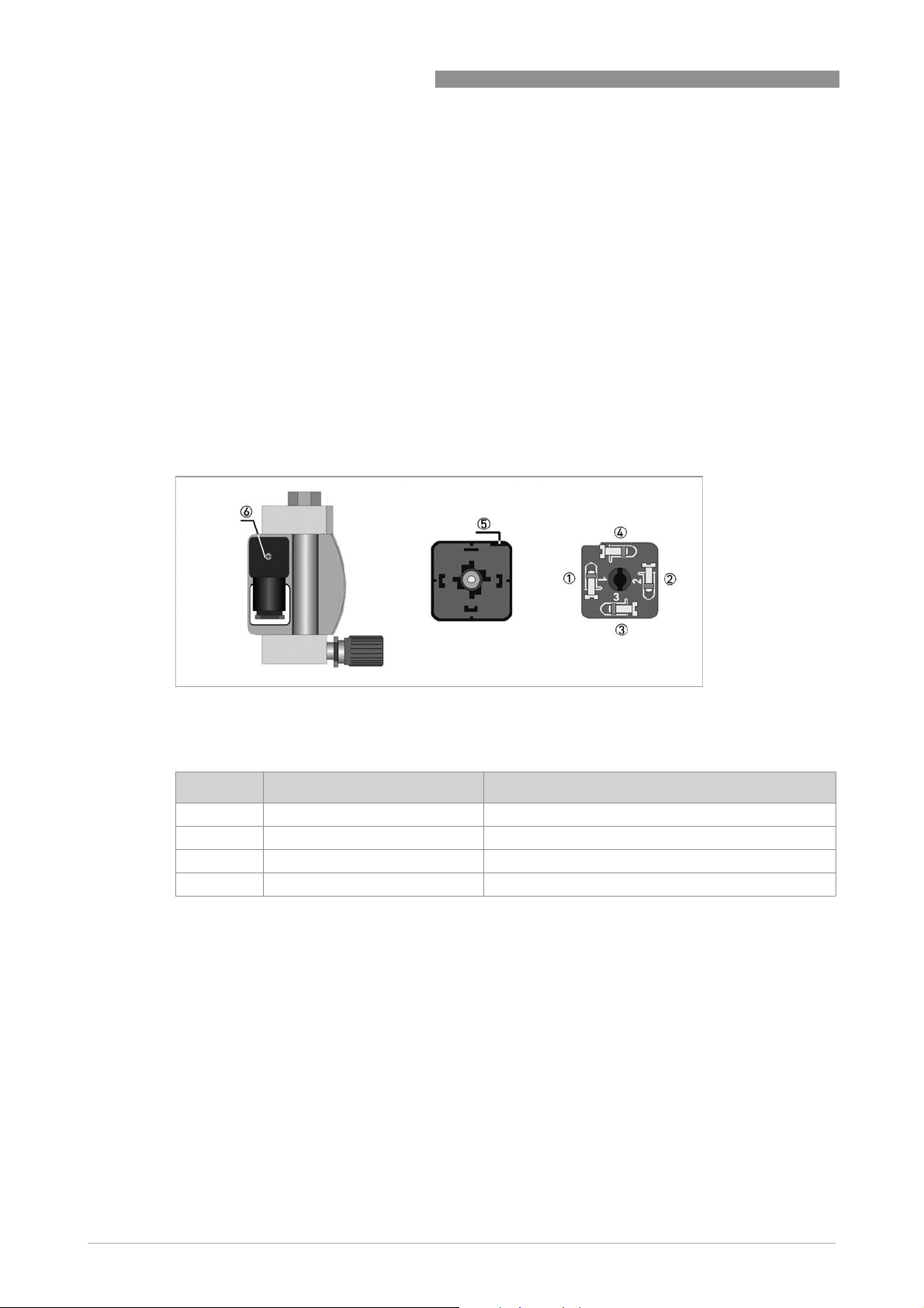
4
ELECTRICAL CONNECTIONS
4.1 Electrical connection of the limit switches
The electrical connection of the limit switches is made for
• DK../../S - in connection plug
• DK../../L - via a cable assembly
The following procedures are to be performed (DK../../S):
• Loosen the screw 6 of the connector plug
• Pull out the plug.
• Remove the screw 6 completely from the plug.
• Insert a screwdriver in the marked opening 5 (lift) and remove the terminal block.
• Lead the connection cable through the cable gland.
2
• Insert the cable (max. 1.5 mm
) and tighten it.
DK32 - DK34 - DK37
Figure 4-1: Electrical connection of the limit switches
5 Lift slot
6 Fastening screw of connection box
Contact connection Stranded wire colour for cable assembly
1 Min minus white
2 Min plus yellow
3 Max minus green
4 Max plus brown
Table 4-1: Contact connections
26
www.krohne.com 11/2018 - 4000282606 - TD DK32-34-37 R07 en
Page 27

DK32 - DK34 - DK37
Figure 4-2: Connection of 3-wire reed contact
1 Silicone-insulated wire - yellow/green / FEP-insulated wire - red
2 Silicone-insulated wire - brown / FEP-insulated wire - brown
3 Silicone-insulated wire - blue / FEP-insulated wire - blue
Table 4-2: Stranded wire colour for devices with cable assembly
ELECTRICAL CONNECTIONS
4.2 Electrical signal output ESK3x for DK32, DK34
4
Figure 4-3: Electrical connection of ESK3x
1 Lock screw
2 Terminal block
3 Power supply 12...32 VDC
4 Measuring signal 4...20 mA
5 External load, HART
®
communication
The following procedures are to be performed:
• Loosen the lock screw 1 on the locking mechanism using an Allen key (WS3).
• Unscrew the cover.
• Connect the connecting cables to the device terminals in the terminal block 2 by ensuring the
correct polarity.
• Screw on the cover.
• Tighten the lock screw on the locking mechanism using an Allen key (WS3).
For devices intended for use in hazardous areas with dust-resistant housing and/or secondary
pressure containment, the special conditions for sealing the electronic compartment and for the
cable entry are available in the supplementary instructions.
www.krohne.com11/2018 - 4000282606 - TD DK32-34-37 R07 en
27
Page 28

4
ELECTRICAL CONNECTIONS
4.2.1 Power supply
The supply voltage has to be between 12 VDC and 32 VDC. This is based on the total resistance of
the measuring loop. To calculate this, the resistance of each component in the measuring loop
(not including the device) must be added up.
The required supply voltage can be calculated using the following formula:
= RL * 22 mA + 12 V
U
ext
with
U
= minimum supply voltage
ext
R
= total measuring loop resistance
L
The power supply has to be able to supply a minimum of 22 mA.
4.2.2 Load for HART communication
®
For HART
communication a load of at least 230 Ω is required.
DK32 - DK34 - DK37
The maximum load resistance is calculated as follows:
= (U
R
L
ext
Use a twisted two-core cable to prevent electrical interference from impeding the DC output
signal.
In some cases a shielded cable may be necessary. The cable shield may only be grounded
(common ground connection) at one point (on the power supply unit).
4.2.3 Configuration
The ESK3x electrical signal output can be configured via HART® communication. DDs (Device
Description) and DTMs (Device Type Manager) are available for the configuration.
They can be downloaded free of charge from our website.
The current flow rate can be transmitted using the integrated HART
counter can be configured. Two limit values can be monitored. The limit values are assigned
either to flow values or to the counter overflow.
- 12 V) / 22 mA
®
communication. A flow
28
www.krohne.com 11/2018 - 4000282606 - TD DK32-34-37 R07 en
Page 29
DK32 - DK34 - DK37
ELECTRICAL CONNECTIONS
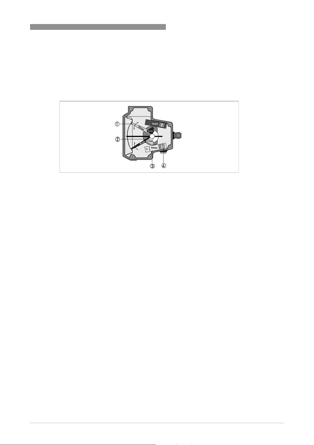
4.3 Settings of limit switches for DK37/M8M
The limit switches can be set over the entire measuring range using the maximum pointer.
The set limit values are displayed on the scale. The pointers are set to the desired limit values
using a slip coupling along the scale.
Figure 4-4: Position of the limit switch
1 Maximum pointer, switching point indicator
2 Limit switches
3 Connection board
4 Connection terminal
4
If the pointer vane goes into the slot, an alarm is triggered. An alarm is also triggered in the
event of a cable break or short circuit if a suitable amplifier is used.
www.krohne.com11/2018 - 4000282606 - TD DK32-34-37 R07 en
29
Page 30
4
ELECTRICAL CONNECTIONS
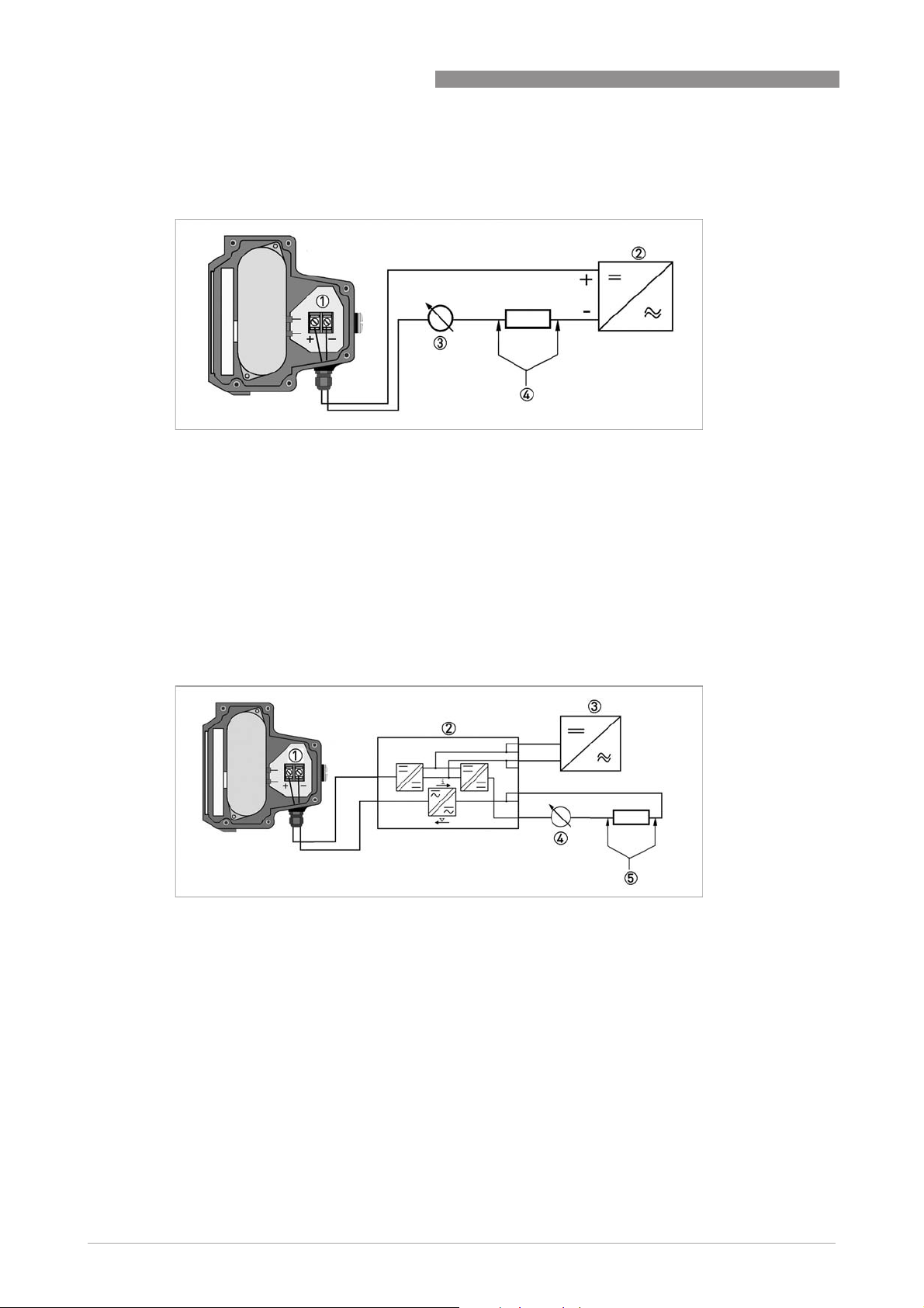
4.4 Electrical signal output for DK37/M8E
Figure 4-5: Electrical connection M8E
1 Terminal connection
2 Power supply 14.8...30 VDC
3 Measuring signal 4...20 mA
4 External load, HART
®
communication
DK32 - DK34 - DK37
Wiring must be planned with great care when it comes to connecting other devices such as
evaluation units or process control. Internal connections in these devices (e.g. GND with PE,
mass loops) may lead to non-permitted voltage potentials which could negatively affect the
function of the device itself or that of a device connected to it. In such cases a protected extralow voltage (PELV) is recommended.
Figure 4-6: Electrical connection with galvanic isolation
1 Terminal connection
2 Signal converter isolator with galvanic isolation
3 Power supply (refer to isolator information)
4 Measuring signal 4...20 mA
5 External load, HART
®
communication
30
www.krohne.com 11/2018 - 4000282606 - TD DK32-34-37 R07 en
Page 31

DK32 - DK34 - DK37
4.4.1 Power supply
The supply voltage has to be between 14.8 VDC and 30 VDC. This is based on the total resistance
of the measuring loop. To calculate this, the resistance of each component in the measuring loop
(not including the device) must be added up.
The required supply voltage can be calculated using the following formula:
= RL * 22 mA + 14.8 V
U
ext
with
U
= minimum supply voltage
ext
R
= total measuring loop resistance
L
The power supply has to be able to supply a minimum of 22 mA.
4.4.2 Load for HART communication
®
For HART
communication a load of at least 230 Ω is required.
ELECTRICAL CONNECTIONS
4
The maximum load resistance is calculated as follows:
= (U
R
L
ext
Use a twisted two-core cable to prevent electrical interference from impeding the DC output
signal.
In some cases a shielded cable may be necessary. The cable shield may only be grounded
(common ground connection) at one point (on the power supply unit).
4.4.3 Configuration
The M8E electronic indicator can be configured via HART® communication. DDs (Device
Description) and DTMs (Device Type Manager) are available for the configuration.
They can be downloaded free of charge from our website.
The current flow rate can be transmitted using the integrated HART
counter can be configured. Two limit values can be monitored. The limit values are assigned
either to flow values or to the counter overflow. The limit values are not depicted on the display.
- 14.8 V) / 22 mA
®
communication. A flow
www.krohne.com11/2018 - 4000282606 - TD DK32-34-37 R07 en
31
Page 32
4
ELECTRICAL CONNECTIONS
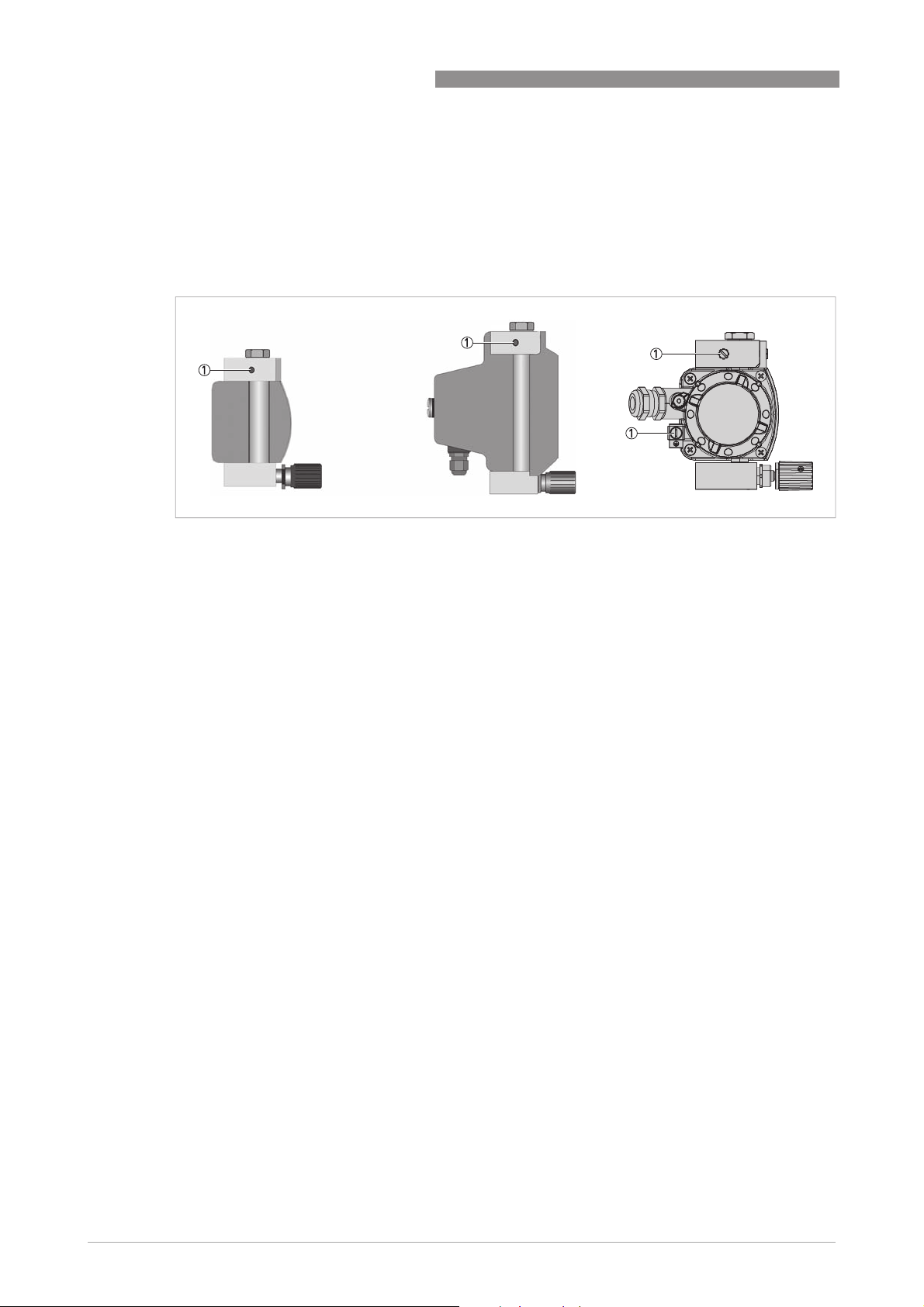
4.5 Grounding connections
The measuring unit is grounded on the top fitting 1 (M4 threaded holes).
Alternatively, the DK32 and DK34 with ESK3x transmitter can be grounded at the transmitter
housing.
DK32 - DK34 - DK37
Figure 4-7: Grounding connections
1 Grounding connection at measuring unit
The grounding wire may not transfer any interference voltage.
Do not use this grounding cable to ground any other electrical devices.
32
www.krohne.com 11/2018 - 4000282606 - TD DK32-34-37 R07 en
Page 33
DK32 - DK34 - DK37
4.6 Ingress protection
The variable area flowmeters DK32 / DK34 / DK37 have been tested for IP protection in
accordance with EN 60529. The following protection categories have been achieved:
Device variant Ingress protection according to EN 60529
DK32, DK34 mechanical IP66/IP68
DK32, DK34 with limit switches K1/K2 IP65
DK32, DK34 with transmitter ESK3x IP66/IP68
DK37 with PPS indicator IP66
DK37 with stainless steel indicator IP66/IP67
After all servicing and maintenance work on the measuring device, the specified ingress
protection category must be ensured again.
Therefore it is essential to observe the following points:
• Use only original gaskets. They must be clean and free of any damage. Defective gaskets must
be replaced.
• The electrical cables used must be undamaged and must comply with regulations.
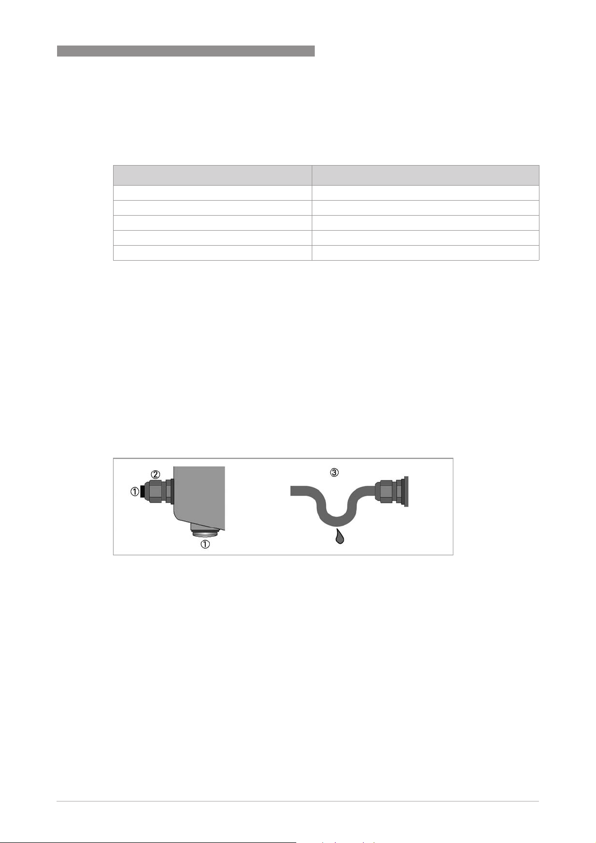
• The cables must be laid with a loop 3 upstream of the measuring device to prevent water
from getting into the housing.
• The cable feedthroughs 2 must be tightened.
• Close the unused cable feedthroughs using blind plugs 1.
• Do not remove the required cable bushing from the cable feedthrough.
ELECTRICAL CONNECTIONS
4
Figure 4-8: Cable feedthrough
1 Use blanking plugs if no cable is routed through
2 Tighten the protection cap
3 Lay the cable in a loop
www.krohne.com11/2018 - 4000282606 - TD DK32-34-37 R07 en
33
Page 34
5
ORDER FORM
Please provide us with the missing information so that we can be of help to you as quickly as
possible.
Then please fax this page to the appropriate sales associate. We will then contact you as soon as
possible.
Device data
Connection type: _ 1/4 NPT _ (others)
Connection: _ Horizontal _ Vertical
Pressure rating:
Indicator: _ DK32 _ DK34 _ DK37/M8M _ DK38/M8E
Indicator options: _ K1 1
Differential pressure
regulators:
Approval: _ None _ ATEX _ QPS (US/C) _ NEPSI
_ K2 1
_ R1 2
_ ESK 3
_ Inlet pressure
regulator
DK32 - DK34 - DK37
_ K1 1
_ K2 1
_ R1 2
_ ESK 3
_ Outlet pressure regulator
_ IECEx _ Others:__________________
_ K1 1
_ K2 1
_ ESK 3
1 NAMUR limit switch
2 Reed limit switch
3 4...20 mA / HART
®
Rating data
Medium:
Operating pressure: _ Absolute
pressure
Rated pressure:
Operating temperature:
Rated temperature:
Density: _ Standard density _ Operating density
Viscosity:
Flow range:
Comments:
_ Gauge pressure
Contact data
Company:
Contact person:
Telephone number:
Fax number:
E-mail:
34
www.krohne.com 11/2018 - 4000282606 - TD DK32-34-37 R07 en
Page 35

DK32 - DK34 - DK37
NOTES
6
www.krohne.com11/2018 - 4000282606 - TD DK32-34-37 R07 en
35
Page 36

K
K
K
KROHNE – Process instrumentation and measurement solutions
•
Flow
•
Level
•
Temperature
•
Pressure
•
Process Analysis
•
Services
© KROHNE 11/2018 - 4000282606 - TD DK32-34-37 R07 en - Subject to change without notice.
Head Office KROHNE Messtechnik GmbH
Ludwig-Krohne-Str. 5
47058 Duisburg (Germany)
Tel.: +49 203 301 0
Fax: +49 203 301 10389
[email protected]
The current list of all KROHNE contacts and addresses can be found at:
www.krohne.com
 Loading...