

Page 1
c
7025282200 www.krohne.com
KROHNE 11/2007
GR
Installation and
Operating Instructions
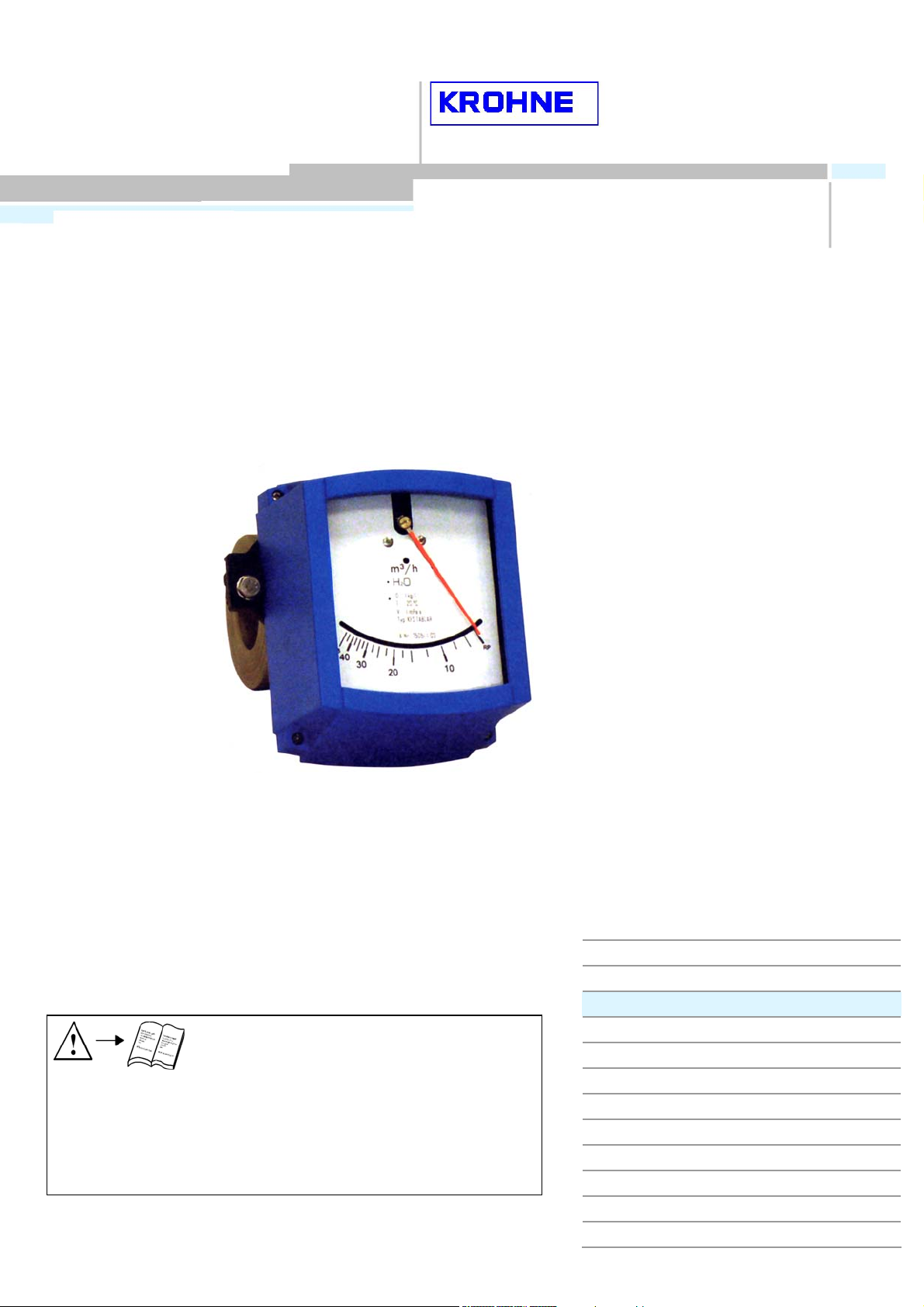
SDA
Flap-type flowmeter
for liquid measurements
Note In case of instruments which are explosion prote
please observe the supplementary installation and operating
instructions:
SDA/... Kat. II2G with electr. internals Id. Nr. 702529##00
Variable area flowmeters
Vortex flowmeters
Flow controllers
Electromagnetic flowmeters
Ultrasonic flowmeters
Mass flowmeters
Level measuring instruments
Communications technology
Engineering systems & solutions
Switches, counters, displays and recorders
Heat metering
Pressure and temperature
Page 2

Table of Contents
Product liability and warranty ...............................................................................................................3
1 General............................................................................................................................................4
1.1 Description code ..........................................................................................................................4
1.2 Marking ........................................................................................................................................4
1.3 Key for Pressure Equipment Directive.........................................................................................5
1.4 Functional principle......................................................................................................................5
2 Installation and Start-up................................................................................................................6
2.1 Prerequisite for the installation ....................................................................................................6
2.3 Preparation of the pipeline...........................................................................................................6
2.4 Observance of the IP degree (NEMA Type) of protection........................................................... 6
3 Flow table........................................................................................................................................7
4 Materials..........................................................................................................................................7
5 Technical Data................................................................................................................................8
6 Measuring temperatures ...............................................................................................................8
7 Dimensions.....................................................................................................................................9
8 Indicator part..................................................................................................................................10
8.1 Contact inserts.............................................................................................................................10
8.1.1 Electrical connection....................................................................................................................10
8.1.2 Limit setting..................................................................................................................................12
8.1.3 Switch contact definition ..............................................................................................................12
8.1.4 Technical data of limit switches ...................................................................................................13
8.2 Electrical signal output ESK.........................................................................................................14
8.2.1 Electrical connection....................................................................................................................14
8.2.2 HART
TM
communication with the ESK .........................................................................................14
8.2.3 Technical data of ESK II ..............................................................................................................15
9 Service ............................................................................................................................................15
9.1 Contact insert...............................................................................................................................15
9.2 Installing an ESK .........................................................................................................................15
10 Maintenance ...................................................................................................................................16
Information on returning instruments..................................................................................................17
Form for returning the instrument........................................................................................................20
Page 3

Product liability and warranty
The flowmeter is suitable for measuring the volume flow of liquids.
Special regulations apply for use in explosion-hazardous areas. (Refer to the section on the scope of delivery.)
Responsibility for the suitability and usage to the intended purpose of these flowmeters rests solely with the operator.
Improper installation or improper operation of the flowmeters may lead to the loss of warranty. In addition, the "General
conditions of sale" which form the basis of the purchase contract are applicable.
The calculation of the pressurized parts is effected with allowance for corrosion, erosion through abrasion or cavitation.
If the flowmeter needs to be returned to KROHNE Messtechnik, please note the information at the end of these
installation and operating instructions.
Scope of delivery
● Installation and operating instructions Ident. No.: 702124##00
● Supply without installation accessories (screw bolts, flange seal and cabling)
Special certificates (supplied to order only)
● Test certificate to EN 10204:
● Pressure test, paint penetration test, irradiation test, leak test,
ultrasonic test, heIium leakage test,
● Cleaning pursuant to works regulations
● Calibration certificate
Page 4
1 General
1.1 Description code
The description code consists of the following elements: *)
1 2 3 4
1 Series measuring unit SDA
2 Display part series
M9 : Standard indicator
M9S : with added corrosion prevention
M9R : Stainless steel housing
3 Electrical signal output
ESK : Analog signal output
4 Limit switch
K1 : One limit switch
K2 : Two limit switches
*) Positions which are not used in the description code are not required.
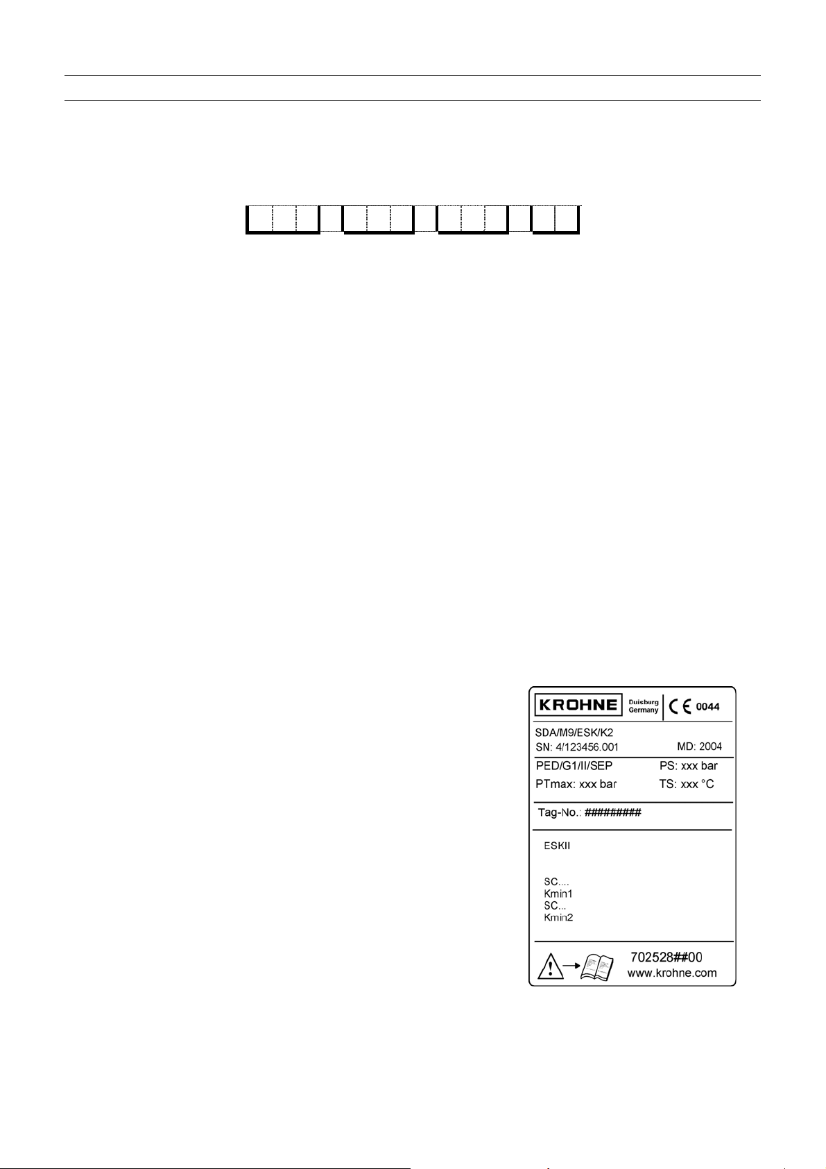
1.2 Marking
The type marking of the complete instrument is carried out at the display part by means of the rating plates shown
here (also refer to the description code).
Example:
MD: Year of manufacturing
PS: Max. permissible operating pressure
at max. permissible operating temperature TS
PT max: Maximum pressure tested
TS: Max. operating temperature
PED: Directive for Pressure Equipment
Tag No : Measuring point tag
0044: Identification number of the supervising office for
EC Directive for Pressure Equipment 97/23/EC
SN: Serial number
SO: Sales order / item
KO: KROHNE order
Vxxxx…: Product configurator code
AC: Article code
Page 5
1.3 Key for Pressure Equipment Directiv e
PED / / /
1 2 3 4 5
1 Pressure Equipment Directive
2 Fluid
G Gases, liquefied gases, gases dissolved under pressure, vapors and those liquids
whose vapor pressure lies more than 0.5 bars over the normal atmospheric pressure
(1013 mbars) at the maximum permissible temperature
L Liquids whose vapor pressure lies a maximum of 0.5 bars above the atmospheric
pressure at the maximum permissible temperature
3 Fluid group
1 Group 1: Explosion-hazardous, highly flammable, readily flammable, flammable
(when the maximum permissible temperature lies above the flash point),
highly toxic, toxic, fire stimulating
2 Group 2: All the fluids not specified in Group 1
4 Category
3.3 In accordance with Article 3.3 of Directive 97/23/EC
I Category I to 97/23/EC
II Category II to 97/23/EC
III Category III to 97/23/EC
5 Conformity evaluation process
SEP Solid engineering practice
A Module A internal process inspection
A1 Module A1 internal process inspection with supervision of the acceptance
H Module H Comprehensive quality assurance
The PED key marking is contained on the rating plate of the instrument.
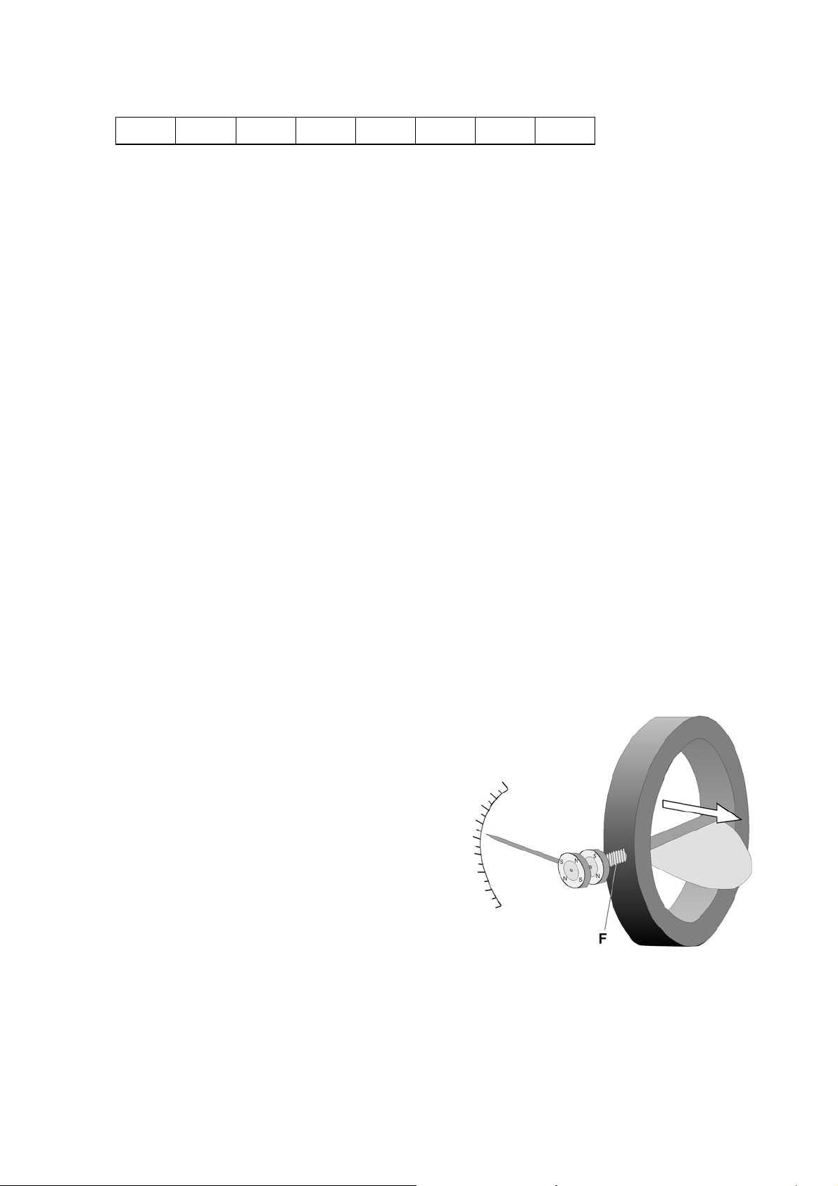
1.4 Functional principle
A half-round plate, or flap, is fastened across the
direction of flow to a springmounted rotating spindle
in a ring that is inserted between flanges in a pipeline.
As the flow rate increases, the flap rotates counter
to the restoring force F of the spring in the direction
of flow.
The ensuing angle of rotation, depending on the
volume rate of flow, is transmitted via a magnetic
coupling to the indicator part.
Page 6

s
s
r
2 Installation and Start-up
2.1 Prerequisite for the installation
The operating pressure of the plant may not exceed the value indicated on the rating plate.
Ensure that the parts coming into contact with the medium are compatible with the material.
The ambient and medium temperatures may not exceed certain maximum values.
In order to prevent distortions the connecting flanges have to face each other axially and in parallel.
2.3 Preparation of the pipeline
Generally comply with the maximum pressure and maximum temperature levels allowable
for the SDA at the measuring point in your plant. The direction of flow must be the same as that
indicated by the flow arrow on the device.
Drain the pipelines before installing the device.
Use gaskets made of rubber or SIL; for plastics devices, use only gaskets made of rubber with
a Shore hardness A of approx. 65°.
The gaskets should not project into the pipeline and the flow meter must be in line with the pipe
axis, otherwise measurements would be falsified and/or the device could jam.
Incorporating the indicator part in the equipotential bonding system in the hazardous area:
The indicator part must be earthed. This can be done e.g. using a wire jumper between the
flange on the indicator part and a pipe flange on the main pipeline with cable lugs appropriate
for the bolted connection (not included with the flow meter!).
Incorporating the indicator in the lightning protection system (if necessary). The Operator is
responsible for checking and determining the scope!
2.4 Observance of the IP degree (NEMA Ty pe) of protection
The following instructions are to be observed in order to observe the IP degree (Nema Type) of electrical built-
in parts:
● After the connecting cable has been introduced, tighten the outlet nut.
● All the cable glands which are not used remain closed with blanking plugs.
● Do not kink lines directly at the cable gland.
● Provide a drain bend
● The feed lines may not be subjected to mechanical strains. Refer to the description
of the electrical supplementary components for this device.
Cable glands / screwed glands:
Thread Material Line diameter Degree of protect Remark
M 16x1.5 PA 5 - 10 mm IP 68 - 5 bars Standard
M 20x1.5 PA 8 - 13 mm IP 68 - 5 bars
M 16x1.5 Nickel-plated bras
M 20x1,5 Nickel-plated bras
5 - 9 mm IP 68 - 5 bars
10 - 14 mm IP 68 - 10 ba
* Degree of protection is limited here to the cable screwed gland
Page 7

3 Flow table
Reference conditions: Water at 20°C
The turn-down range amounts to 10 : 1
The specified pressure losses apply for water and air at the maximum flow rate.
Nominal size Flow Water
DN Inch m3/h US GPH
25 1 6 - 12 1585 - 3170
32 1 1/4" 8 - 15 2113 - 3962
40 1 1/2" 6 - 25 1585 - 6604
50 2" 5 - 30 1320 - 7925
65 2 1/2" 20 - 80 5283 - 21133
80 3" 40 - 80 10566 - 21133
100 4" 40 - 120 10566 - 31700
125 5" 65 - 150 17171 - 39625
150 6" 80 - 225 21133 - 59438
200 8" 150 - 350 39625 - 92460
250 10" 150 - 350 39625 - 92460
300 12" 250 - 750 66043 - 198129
4 Materials
Ring
Corrosion protection for steel version
Scale casing
Pointer
Scale
Pane
Steel
Stainless steel 1.4571
PVC (up to DN300)
PP (up to DN300)
PVDF (up to DN300)
Epoxy, stove enamelled, colour: blue, RAL 5017
Aluminium, painted
Aluminium, painted
Aluminium, coated
Float glass
Page 8

5 Technical Data
Flow range min
max
Accuracy
Turndown ratio
Nominal sizes
Max. Operating pressure Standard
Option
0,5 ... 6 m3/h Water
150 ... 1500 m
3
/h Water
5% FS
min. 1 : 10
DN25 ... DN300
PN 6/10
PN 16/25/40
Mounting length Standard
Special spring
Connection Standard
Option
50 mm
60mm
Mounting between welding neck flanges to DIN 2501
ASME, JIS
Degree of protection, indicator part IP 67
6 Measuring temperatures
Type of Steel, stainless steel
PVC
PP
PVDF
- 70° C ... + 200° C
0° C ... + 20° C /10bar - 0° C ... + 40° C /6bar
0° C ... + 20° C /10bar - 0° C ... + 80° C /1,5bar
-40° C ... + 20° C /10bar - -40° C ... + 140° C / 2bar
Page 9

7 Dimensions
DN
d4 [mm] A [mm]
25 68 232,5
32
78 236,0
40 88 240,0
50 102 245,0
65 122 252,5
80 138 260,0
100 158 270,0
125 188 282,5
150 212 295,0
200 268 320,0
250 320 345,0
300 370 370,0
350 430 395,0
400 482 420,0
500 585 485,0
600 685 530,0
Standard ring C = 50mm (Option: 60mm)
Page 10

8 Indicator part
8.1 Contact inserts
The flowmeter SDA can be equipped with a maximum of two electronic limit
switches.
The limit switch functions with a slot-type initiator which is
operated inductively through the semicircular metal vane
belonging to the measuring pointer. The switching points
are set through the contact pointer. The setting of the
contact pointer serves at the same time for the optical display of the
set limit.
Contact types: 1 Limit switch
SC3,5-N0-Y 2-wire technology (NAMUR) 2 Contact pointer
SJ3,5-SN 2-wire technology safety-oriented 3 Connecting plug
SJ3,5-S1N 2-wire technology safety-oriented (inverted) 4 Connecting terminal
SB 3.5-E2 3-wire technology 5 Terminal socket
8.1.1 Electrical connection
The housing cover of the M9 display has to be removed in order to connect the contact insert. The connecting
terminals (4) have a pluggable design and can be removed in order to connect the lines. The built-in contact types are
listed in the rating plate of the display.
Electrical connection of the limit switches in 2-wire technology
Connection assignment for
SC3,5-N0-Y
SJ3,5-SN
SJ3,5-S1N
Contact MIN MAX
Connector color black gray
Labeling 1 2 3 4 5 6
2-wire technology - + - +
Electrical connection of the limit switches in 3-wire technology
Connection assignment for
SB3,5-E2
Contact MIN MAX
Connector color black gray
Labeling 1 2 3 4 5 6
3-wire technology + DC - + DC -
Connection diagram 3-wire technology
Page 11

Connection diagram 2-wire technology
NAMUR Safety-oriented *
SC3,5-N0-Y SJ3,5-SN and SJ3,5-S1N
Inputs Input
Terminals Terminal
in the in the
display display
Output I Output II Power Output III II Output I Power
LED yellow output LED green power LED yellow
Relay output
Switch S1 LED red LB/LK
Effective direction I LED red
Switch S2 LB/LK recognition
Switch S3 Effective direction II
LB/LK recognition LED green
Power
LB : Line break * Safety-oriented isolating switching amplifiers
LK : Line short-circuit are only single-channel!
Page 12

8.1.2 Limit setting
The setting is carried out directly via the contact pointer (2): Scale opening
- Slide the scale away
- Loosen the locking screw (1) slightly
- Slide the scale back to the latching point
- Set the contact pointer (2) to the desired switching point
- After setting, the contact pointer (2) is to be fastened
hand-screwed again with the locking screw (1) (max. 40 Ncm).
- Screw on the housing cover.
.
8.1.3 Switch contact definition
MIN contact
If the pointer vane (1) enters the slot, an alarm is triggered. If the
pointer vane lies outside the slot initiator, a wire break also causes
the alarm to be triggered.
No wire break recognition at SB3,5-E2
Option: Implementation as a maximum contact
In the alarm status the vane lies outside the slot.
Wire break recognition is not available here.
MAX contact
If the pointer vane (1) enters the slot (and thus dampens this initiator),
an alarm is triggered. If the pointer vane lies outside the slot initiator,
a wire break also causes the alarm to be triggered.
No wire break recognition at SB3,5-E2
Option: Implementation as a minimum contact
In the alarm status the vane lies outside the slot.
Wire break recognition is not available here.
Page 13

Definition of Min1 and Min2 / Max1 and Max2
Min1
Min2
Max1
Max2
8.1.4 Technical data of limit switches
current consumption
with the shown
pointer position
SC3,5-N0 ≤1 mA
SJ3,5-S1N ≤1 mA
current consumption
with the shown
pointer position
SJ3,5-S1N ≥3 mA
SC3,5-N0 ≥3 mA
SC3,5-N0-Y SJ3,5-SN SJ3,5-S1N SB3,5-E2
2-wire 2-wire 2-wire 3-wire
NAMUR NAMUR NAMUR
Switching element function NC contact NC contact NO contact NO contact PNP
Nominal voltage U0 8 V 8V 8V 10 to 30 V
Power consumption:
Pointer vane not detected
Pointer vane detected
≥ 3 mA ≥ 3 mA ≤ 1 mA ≤ 0.3 V
≤ 1 mA ≤ 1 mA ≥ 3 mA
Ub - 3 V
Continuous current - - - max. 100 mA
No-load current I0 - - -
≤ 15 mA
An isolating switching amplifier, e.g. Pepperl + Fuchs Series KF .. -SR2 ..., is required in order to
operate the SC3,5-N0-Y limit switch (refer to the chapter on the spare part list).
SJ3,5-SN and SJ3,5-S1N limit switches safety-oriented are connected to a safety-oriented isolating
switching amplifier, e.g. Pepperl + Fuchs K… –SH- ... (large S on the front)
Page 14

8.2 Electrical signal output ESK
8.2.1 Electrical connection
The connecting terminals of the M9 display have a pluggable design and can be removed in order to
connect the lines.
8.2.2 HART
HART
When HART
measured value transfer (4...20mA)
Exception at Multidrop operation. In Multidrop operation a maximum of 15 instruments with HART
TM
communication with the ESK
TM
communication is not compellingly required in order to operate the ESK.
TM
communication is carried out with the ESK, this does not by any means impair analog
TM
function can be operated in parallel, whereby their current outputs are switched inactive (approx. 4 mA).
If a HART
the resistor which is connected in series (R
TM
communicator (type Fisher Rosemount, Model 275) or a PC with HART
) has to exceed 250 Ohms.
ext.
TM
modem PC is used,
In this type of operation the auxiliary power must amount to at least 18 V. The communicator or the PC is
connected as shown in the drawing above.
It can be operated optionally via the connecting terminals of the ESK (2) or via an external resistance (1)
connected in series. The counter cannot be read out or operated by means of HART
TM
communication!
Page 15

8.2.3 Technical data of ESK II
Auxiliary power 12 (18 * ) to 30 V DC
Measurement signal 4.00 to 20.00 mA for 0 to 100 % flow value
> 20.8 mA for alarm status
Auxiliary power influence < 0.1%
Dependency on external resistance < 0.1%
Temperature influence < 5 μA / K
Max. external resistance / load 0 (250 * ) to 800 Ohms
* These values are to be observed as minimum values during HART
TM
communication.
9 Service
9.1 Contact insert
Bring the contact pointers (1) together in the center
Loosen the locking screw (2) of the contact pointers
Slide the contact insert into the third rail until the semicircle (3)
encloses the pointer support.
The connecting terminals of the contact insert have a pluggable
design and can be removed in order to connect the lines.
9.2 Installing an ESK
Assembly is based on the plug-in technique.
Insert the push-in lugs of the ESK under the
two studs of the baseplate (1).
Using slight pressure, press the ESK on to
the spring bolt (2) until it locks home and is securely
fastened.
Page 16

10 Maintenance
The flowmeter is also to be inspected for soiling, corrosive erosion and mechanical wear or damage to the measuring
tube and the display in the context of the routine operational maintenance of the installation and the pipelines. We
recommend at least annual inspections. In order to clean the instrument remove it from the pipeline.
Note
Pressurized lines have to be relieved before the measuring unit is removed.
Corresponding safety precautions with regard to residual liquids in the measuring unit in case of instruments which are
used to measure aggressive media.
New seals must always be used when remounting the measuring unit in the pipeline.
Electrostatic charges are to be avoided when the surfaces (e.g. viewing window) are cleaned!
Maintenance
The device is normally maintenance-free. Should it become soiled, it will need
to be removed from the pipeline for cleaning. Devices fitted with contacts
must be disconnected from supply and de-energized.
To dismantle the device you will need the following tools:
2x open-jawed spanner, jaw span 13mm
1x open-jawed spanner, jaw span 7mm
1x screwdriver 4x 0.6mm
1x socket spanner, size 7mm up to DN 100 or
1x socket spanner, size 8mm, up to DN 250 or
1x socket spanner, size 10mm, for DN 300 and higher.
Required spares: 2x gasket
If necessary, wear personal protective gear (safety goggles,
protective gloves, conductive footwear).
Depressurize the pipe.
Caution: Slacken screws/bolts only when the system has been deenergized, the pipe depressurized and free of fluid product.
Drain the pipes.
Remove the device from the pipeline in the reverse order
Detach the dial gauge with magnet casing from the neck of the
device by removing the four M8 screws (Item 1 or 2).
Unscrew the fastening screws (3) between spindle and flap (4).
Pull the spindle together with the magnet casing and the spring
assembly (5) out of the device.
Clean all mechanical parts with appropriate cleaning agents. If
necessary, clean the indicator part with a damp cloth that has been
rinsed in soap suds and wrung out.
Reassemble in the reverse order, paying special attention to the
position of the flap. The bearing marked with a centre punch must
point towards the spring. Do not change the original orientation of
the flap (maintaining the direction of rotation appropriate to the
indicator part ). The flap requires a minimum of 1 mm clearance on
both sides (risk of jamming and sparking).
Hazardous areas: Do not on any account remove the labelling on
the scale casing containing information on explosion protection.
Page 17

Information on returning instruments
Your instrument has been manufactured carefully and
tested several times. If installed and operated in
accordance with these instructions your instrument will
rarely present any problems. Should you nevertheless
need to return an instrument for checking or repair, please
pay strict attention to the following points:
Due to statutory regulations concerning protection of the
environment and safeguarding the health and safety of
our personnel, KROHNE may only handle, test and repair
returned instruments that have been in contact with liquids
if it is possible to do so without risk to personnel and
environment.
This means that KROHNE can only service your device if
it is accompanied by a certificate in line with the following
model confirming that the device is safe to handle.
If the instrument has been operated with toxic, caustic,
flammable or water-endangering liquids, you are kindly
requested:
- To check and ensure, if necessary by rinsing
or neutralizing, that all the cavities in
the instrument are free from such dangerous
substances. (Directions on how you can find out whether
the primary head has to
be opened and flushed out and neutralized
are obtainable from KROHNE on request.)
- To enclose a certificate with the device confirming that
the device is safe to handle and
stating the liquid used.
KROHNE regret that we cannot service your device
unless it is accompanied by such a certificate and thank
you for your understanding.
Page 18

Page 19

SDA Installation and operating instructions 19
Page 20

Form for returning the instrument
Company: ..................................................... Address: .......................................................................
Department: .................................................. Name: ..........................................................................
Tel. No.: ........................................................ Fax. No.: ......................................................................
The enclosed instrument
Type:...............................................................................................................................................................
KROHNE Order No. or Series No.: ................................................................................................................
has been operated with the following process liquid: .....................................................................................
Because this process liquid is water-endangering * / toxic * / caustic * / flammable *
we have
- Checked that all cavities in the instrument are free from such substances *
- Flushed out and neutralized all cavities in the instrument *
(* delete where not applicable)
We confirm that there is no risk to man or environment through any residual liquid contained in the instrument.
Date: ............................................................. Signature.......................................................................
Company stamp:
SDA Installation and operating instructions 20
 Loading...