

Page 1
Version November 1996
CORIMASS P and E Series
Software Version P2.20
Installation a nd
Operating
Instructions
MFM 2081 K and F
MFM 3081 K and F
Page 2

How to use these installation and operating instr uct i ons
For easy reference these Instructions are divided into four parts.
Only Part A (page 3) is needed for install at ion and initial start-up.
All CORI MASS mass flowmeters of the P- and E-Series are fact or y set t o y our order
specifications.
Part A
Part B
Part C
Part D
The CORIMASS mass fl owmeter MFM 2081 and MFM 3081 is designed for the direct
measurement of mass f l ow rat e, product density and pr oduct temperature, and also indirectl y
enables measurement of parameters such as total m ass, concentrat ion of dissolved
substances and the volume flow.
For use in hazardous areas, special codes and regulations are applicabl e which are specified
in the special “Ex installati on and operati ng instructions“ (s uppl ied only with hazardous-duty
equipment).
Responsibility as to suitability and intended use of our instrum ents rests solely wit h t he
purchaser.
Improper inst allation and operation of t he fl owmeters may lead to loss of warranty.
Install f lowmeter in the pipeline (Sect. 1), connect up (Sect. 2) and power the
flowmeter (Sect. 3).
The system is operati onal
Operator control and f unctions of the MFC 081 Signal Converter.
Service and functional checks.
Technical data and dim ensions.
Product liability and warranty
In addition, t he “general conditions of sale“ for ming the basis of the purchase agreement
are applicable.
If you need to return CORI MASS f lowmeters to KROHNE, pl ease complete the form on t h e
last page of thi s manual and return it wi t h t he m eter to be repaired. Krohne regr et s t hat it
cannot repair or check your fl owmeter unless accompanied by this compl et e d f or m.
CE / EMC St andar ds / Approvals
• The Corimass MFM 2081 and MFM 3081 with the MFC 081 signal converter meet the
requirements of the EU-EMC Direct i ves and bear the CE symbol.
• The Corimass MFM 2081 and MFM 3081 K -Ex are approved as hazardous duty equipment
to the harmonised European Standards and to Factor y Mutual (FM) (pending). Further
details are given in the “Ex” supplementary instructi ons pr ovi ded only wit h hazardous-dut y
equipment.
Technical data subject t o change wi t hout not ice
2
Page 3

Contents
Part A: Installation and Start-up 4 - 28
1. Instrument Descr i pt i on 5
1.1 The Corimass Measuring System 5
1.2 Mass Flow Sensor 6
1.2.1 Measuring Principle 6
1.2.2 Transducer MFS 2000 (P-Series) 6
1.2.3 MFS 3000 Transducer (E-Series) 7
2. Installation 8
2.1 General Principles 8
2.2 Installation Guidelines 9
2.2.1 Location of Corimass Transducer 9
2.2.2 Requirements of the piping system 12
2.2.3 Special remarks on the MFS 3000 15
3. Electrical Inst al lation 17
3.1 Location and Connecting Cables 17
3.2 Connection to Power 17
3.3 Inputs and Outputs 18
4. Start-up 20
4.1 Factory Set Parameters 20
4.2 Initial St ar t-up 20
4.3 Installat ion Factor 21
4.4 Zero Point Adjustment 21
4.5 Programming the Converter with a Bar Magnet 22
4.6 Installat ion of the Converter MFC 081 F 22
4.7 Connection of Remote Mounted Version 23
4.8 Connection Diagram of Compact Version 28
Part B: MFC 081 Signal Converter - Software Version P2.20 29 - 76
5. Operation of t he Si gnal Convert e r 29
5.1 Operating and Check Elements 29
5.2 Krohne Operating Concept 30
5.3 Key Functions 31
5.3.1 How to enter programming mode 32
5.3.2 How to terminate programming mode 32
5.4 Table of Programmable Functions 35
5.5 Reset / Quit Menu - Totalizer Reset and Status Indication Acknowledgement 45
5.6 Status Messages 47
5.7 Menu Variations for Systems with O t her Out put O ptions 48
6. Description of Funct i ons 49
6.1 Zero Point Adjustment 49
6.2 Low Flow Cutoff 51
6.3 Time Constant 51
6.4 Programming the Display for Measurement Values 52
6.5 Programming Numeric Data 55
6.6 Setting the Current Output 56
6.7 Setting the Frequency / Pulse Output 59
6.8 Setting the Process Alarm Output 63
6.9 Setting the Control Input 65
6.10 Setting the System Control 66
6.11 Standby Function 67
3
Page 4

6.12 Density Calibration Adjust ment 69
6.12.1 Water as the reference liquid 69
6.12.2 Process fluid as the reference liquid 69
6.13 Density - Special functions 71
6.13.1 Density - Special functions 71
6.13.2 Referred density (option) 72
6.13.3 Fixed density (option) 72
6.14 User Data 73
6.14.1 Programming the display language 73
6.14.2 Password protection of m enus 73
6.14.3 Custody transfer protection code 74
6.14.4 Primar y head type and tube parameters (CF 1 - 9) 76
6.14.5 Location 76
Part C: Special O pt i ons, Functional Checks, Service and O r der Numbers 77 - 96
7. Special Options 77
7.1 Use in Hazardous Areas 77
7.2 Converter with Non-standard Output O pt ions 77
7.3 Concentration Measurement and Special Density Options 77
7.4 Converter with Smart / HART Communication O pt ion 77
7.5 Converter with RS 485 Communi cat i on O ption 78
7.6 Custody Transfer Option 78
8. Functional Checks 78
8.1 Test Functions 78
8.1.1 Testing the display 78
8.1.2 Testing current output 79
8.1.3 Testing pulse output 79
8.1.4 Testing alarm out put 81
8.1.5 Testing control input 81
8.1.6 Viewing temperature 82
8.1.7 Viewing primar y head signal condi tions 82
9. Service and Troubleshooting 83
9.1 Threads and “O” Ring of the Converter Housing Lid 83
9.2 Replacing the Converter Electronics 83
9.3 Change of Operating Voltage and Power Fuse F9 84
9.3.1 Replacement of power fuse F9 84
9.3.2 Changing the operating voltage 84
9.4 Turning the Display Circuit Board 85
9.5 Turning the Signal Converter Housing 85
9.6 Troubleshooting 86
9.7 Fault Finding 89
9.8 Checking the Primary Head 92
9.9 Status W ar ni ngs 93
10. Order Numbers 96
Part D: Technical Data and Dimensions 97 - 103
11. Technical Data 97
11.1 Primar y Head 97
11.2 MFC 081 Signal Converter 99
11.3 Measuring Accuracy / Error limits 100
11.4 Dimensions and weights 101
11.4.1 Compact Systems - MFS 3081 K / MFS 2081 K 101
11.4.2 Remote Systems - MFS 3081 F / MFS 2081 F 102
4
Page 5
Part A Installation and Start up
1. Instrument Descr i pt i on
1.1 The CORIMASS M easur ing System
The CORIMASS Measuring Sys tem uses the Cori o lis principle for measuring the mas s flow
rate of fluids wit h hi gh accur acy.
When using thi s measuring principl e, it is possible to measure the mass flow rate directl y,
independent of any other parameters of the fluid, such as density, temperature, pressure,
viscosity, conduct i vity and flow profi l e. Hom ogeneously distr i but ed sm all solid particles
(slurries) and gas bubbles have no noticeable effect on the measuring accuracy.
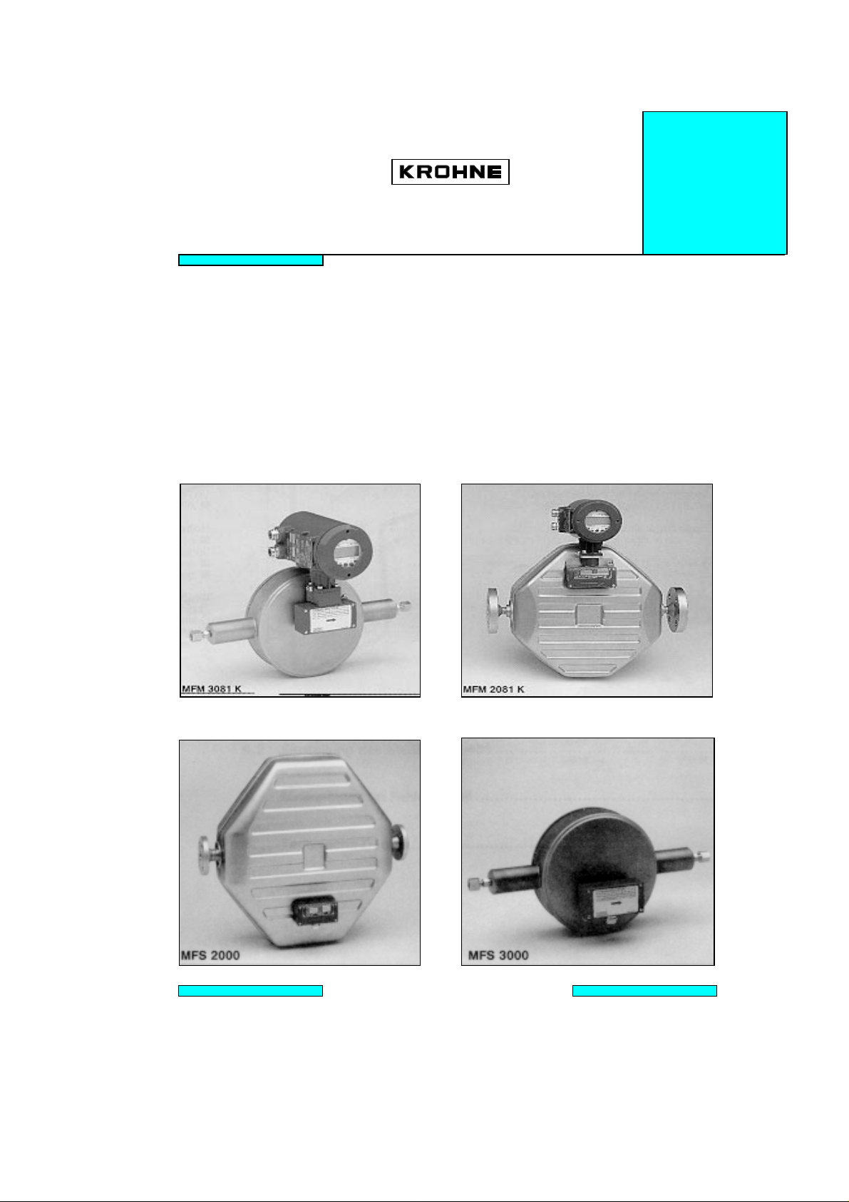
The CORIMASS mass flow rate system i s of modular type design, com pr ising a transducer
and a converter. In the compact version MFM 2081 K / MFM 3081 K the converter is mount ed
directly to the transducer; in t he separate version MFM 2081 / MFM 3081 the transducer MFS
2000 / MFS 3000 and the converter MFC 081 F are connected to each other via a shielded
multi-conductor cable (figur e 1). The MFM 2081 is also referred to as “P-Series,” and the
MFM 3081 is also referred to as “E-Series”. The measurement values of mass flow rate, total
mass and density are available.
Additional to t he standard syst em f or special r equirements the following models are available:
− tr ansducer wit h electri c or liquid heating
− tr ansducer with secondary containment or pressure relief
− hazardous duty model:
EEx ib II B or EEx ib II C (no electric heating!) ar e appli ed
− FM Class I, II, III, Div. 1 and Div. 2, Groups B-G ( pending)
Compact Version Separate Version
MFM 2081 K MFM 2081 F
Transducer MFS 2000 plus Converter MFC 081 F
Shielded multi-conduct or cabl e
Fig. 1 The CORIMASS Measuring System
5
Page 6

1.2 Mass Flow Sensor
1.2.1 Measuring Pr i nci ple
Coriolis for ces occur in r ot at ing systems when accompanying bodies are moved toward or
away from the rotat ional axis. This is illustrated by the following simple set-up: a pipe tube
rotates with a constant angular veloci t y ar ound t he axis A - B (fi gur e 2). The flui d par t icles
flow with the velocity v through t he loop. Between the points C and D they move away from
the axis and therefore have to be accelerated from a smaller to a lar ger tangential veloci t y.
Respectively, the fluid particles have to decelerate reducing their tangential velocity between
points E and F. The opposing coriol i s f or ces acti ng upon t he two dif f erent parts of t he pipe
loop are directly proporti onal to the product of the mass and the velocity of the fluid. They
cause the pipe loop to deform (DD’, EE’ and FF’ respectively) with r espect to a r otating loop
filled with a flowing fluid.
Fig. 2 Coriolis force in a rotating pipe loop
Rotation does not necessarily mean the completion of f ull circular or bi t s. Short circular
segments suffice. In the event of oscillation, the deformation of the pipe loop sides oscillates,
too. The total change in the moti on of t he pipe loop caused by the mass flow can be detected
via inductive sensors. A signal di r ectly r elated the mass f l ow rat e of the fluid flowing through
the pipe loop is then generated after appropriate signal processing.
1.2.2 Transducer MFS 2000 (P-Seri es)
For greater sized mass flow meters it has proven to be of advantage for the fluid t o f low
through two parall el measuring loops, which oscillate in opposite directions and with a phase
difference of 180°. This symmetrical arr angem ent of t he loops and the sti f f ness of the bridge
(i.e. the pipe loop supports) suppress most disturbances caused by external equipment.
Figure 3 displays an optimised transducer of the MFS 2000 series designed for mass fl ow
measurement.
Fig. 3: Transducer MFS 2000 without housing
6
Page 7

The use of flow dividers with optimised flow properties combined with the application of
measuring tubes with a large tube cross-section ensures mini mum loss of pr essure. The
danger of cavitation i n t he specified m easuri ng r ange is eliminated.
The use of thick-walled measuring tubes with a large cross-section exercises a further positive
effect. Due to the increase in the vibrating mass, the measuring system is less sensitive to
gas bubbles in the measured medium.
1.2.3 MFS 3000 Transducer (E- Ser i es)
The CORIMASS MFS 3000 series is comprised of precision transducers f or the measurement
of small fluid and gas mass f low rates with the range of 0.006 kg./mi n. t o 33. 3 kg. /min. ( 0. 013
lb./min. to 73.16 lb./min.).
In contrast to the CORIMASS P-seri es of instr u ments, t h e CORIMASS E-series is d esi g n ed as
a single-tube system with the inherent advantages of a single flow path (see Fig. 4).
Fig. 4: MFS 3000 Transducer without housing
Due to its low-frequency tuned reference platform, t he MFS 3000 is largely insensiti ve to
interference. The unit is characterised by a rugged transducer loop, which permits optional
measurements up to operating pressure levels of as much as 300 bar (4352 psig) depending
on model.
A further advantage of the E-series is its ease of maintenance and servicing.
7
Page 8
2. Installation
2.1 General Princi pl es
The MFS 2000 and MFS 3000 CORIMASS mass flowmeters are capable of providing hi gh
accuracy and excellent repeatability. The narrow band pass digital filtering, the dual parallel
tubes of the P-Series and the tuned reference platform of the E-Series provide exceptional
immunity to external vibratory di st ur bances from process equipment in the area. Furthermore,
the power of the CORIMASS with its dual driver design perm its unsurpassed performance on
certain types of slurries and on li qui ds wi t h gas bubbles. Both designs are self-draining when
installed vertically.*
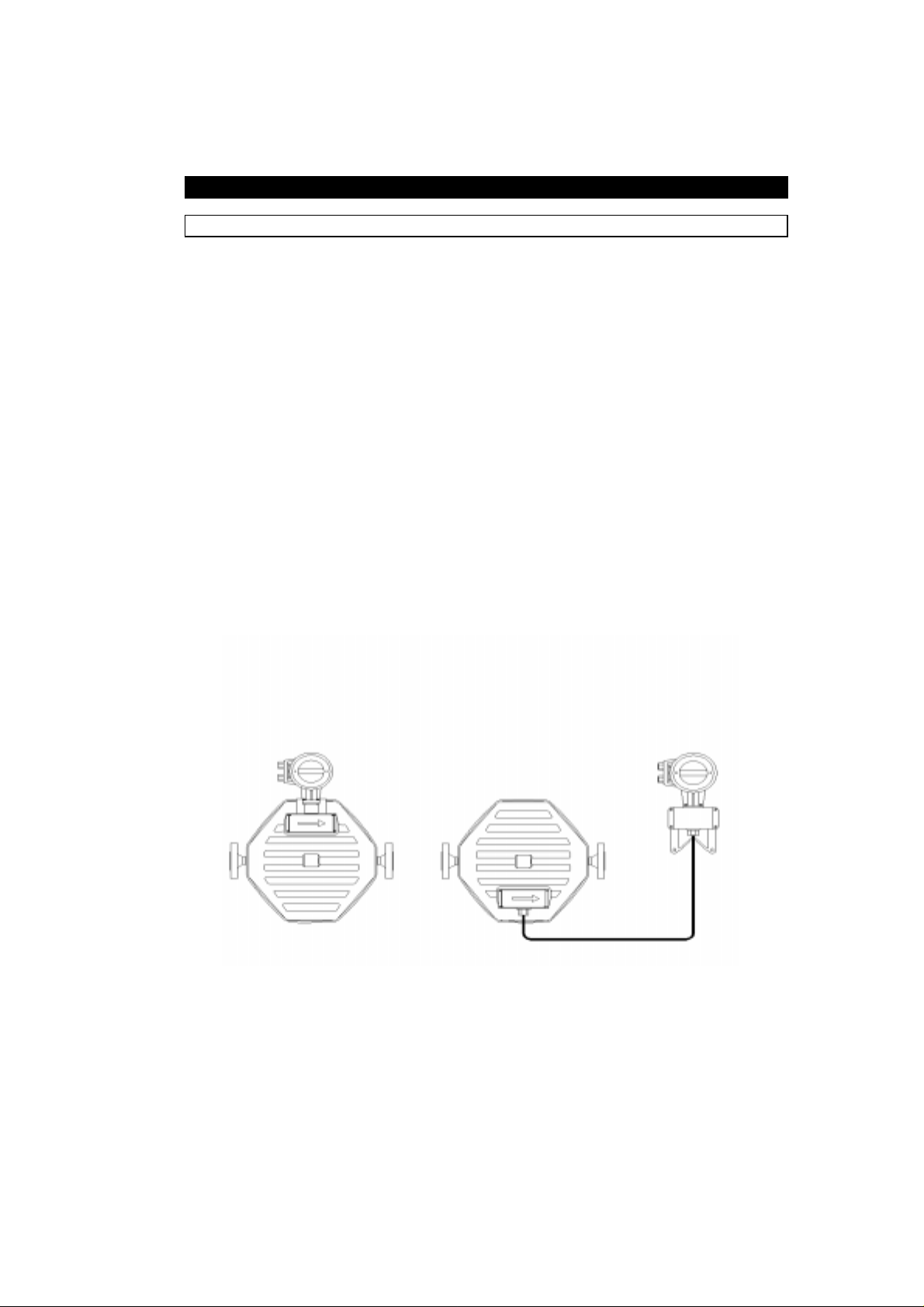
As with all Cori o lis mass flo wmeters, th e CORIMASS is an act ive device with its own energy
source. The MFS 2000 mass flow sensor should be mounted into and by a rigid suppor t i ng
piping system to avoid reflected resonant energy from adjacent piping and mounting st r uct ur es
in order to take advantage of the high degree of precision built int o t he instr ument (fig. 5) . A
possible exception is mentioned in Section 2.2.2.
Fig. 5 Basic inst a lla tion requirement
MFS 2000: rigid, stress free supporting of the tra nsducer
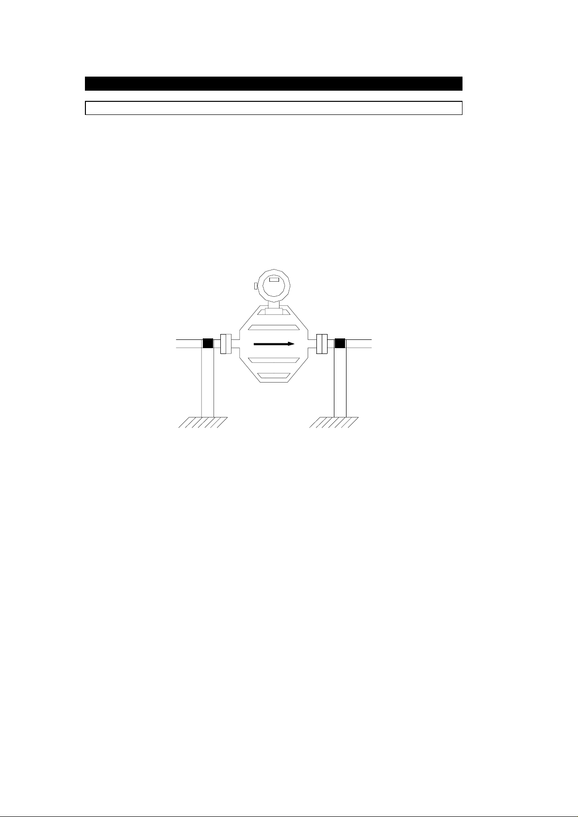
The MFS 3000 transducer should be mounted by using two metallic clamps (supplied with the
flowmeter), which are secured to a rigid mounting surface, as shown. For optimum
performance these clamps should be positi oned near the outboard ends of the transducer
support tubes. They should also be well aligned to prevent undue stress on the MFS 3000
transducer housing when the clamps are secured. Adjacent piping should be rigidly support ed
and aligned with the transducer to avoid excess loading on the transducer process
connections(See Fig. 6). For connection to tubing, pr ocess tubi ng shoul d also be secured at
appropriate locati ons ( indicated by arrows in Fig. 6) t o minimize vibration.
* Note: 1.5E requires aproximately 7° anti-clockwise rotation f r om vertical.
8
Page 9
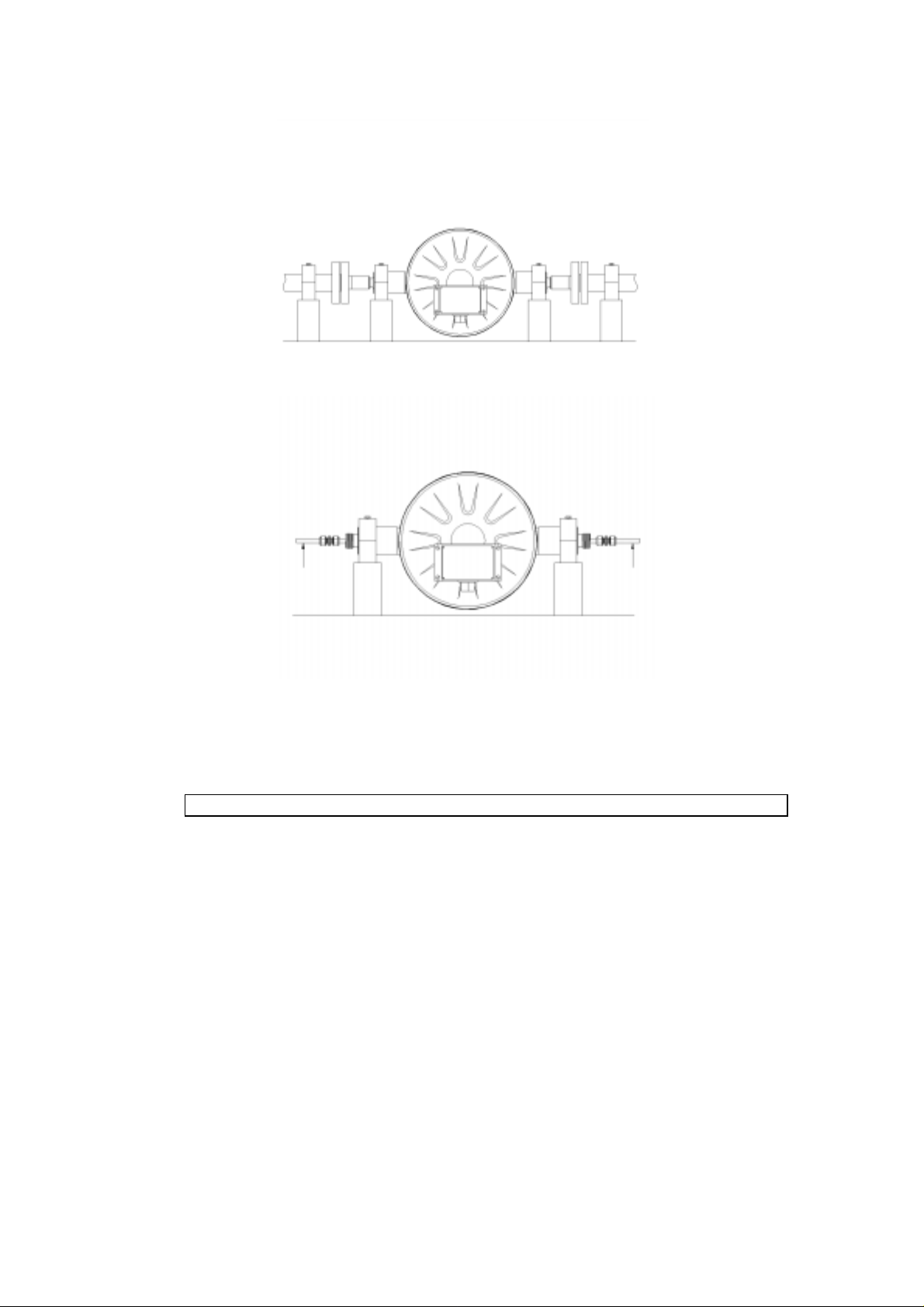
Fig. 6: Installation MFS 3000
A good installation is the basis for the high measurement accuracy of the unit.
The following instal lation guidelines are practical to implem ent, par t iculary if pl anned before
the CORIMASS is first installed.
2.2 Installation Guidelines
2.2.1 Location of CORI MASS Transducer
Please ensure the following install at ion guidelines are adhered to as they are
necessary
The transducer can be installed in any position. However, when installed in a vertical position
the transducer is self-draini ng and allows gas bubbles to be readily purged from f lowmeter
during flowing conditions (see Fig. 7a and 7b).
for good measurement results and trouble-free start-up.
absolutely
9
Page 10
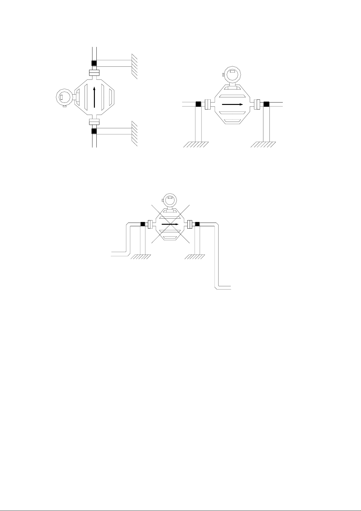
Fig. 7a Vertical installation Fig. 7b Horizontal installation
Highest positi on in Pipeline
Avoid mounti ng t he transducer in t hi s position as gas bubbles may col l ect and rem ai n in
measuring system causi ng i ncor r ect measurements (see Fig. 8).
Fig. 8 Avoid highest position in pipeline
10
Page 11
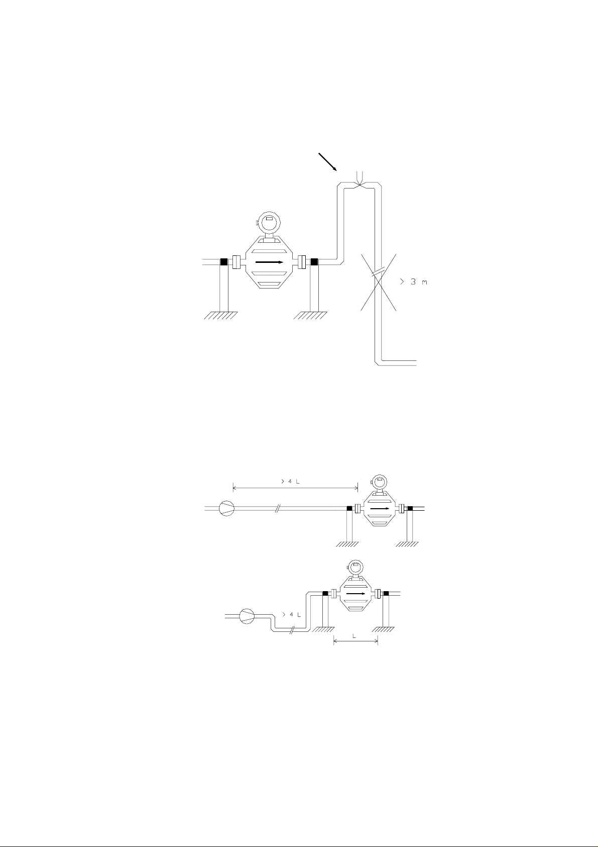
Falling Pipeline
Long downstream pipelines (> 3m ) should be avoided due to degassing of the medium .
If long downstream pi peli nes are unavoidable instal l an additional vent valve as shown in
Figure 9, unless there is under all operating conditions suf f icient back pressure to avoid
flashing of l iquid to vapor.
Fig. 9 Avoid long downstream pipelines after the transducer
Pumps
Pumps should be install ed at least 4 × L fr om the transducer.
Where pumps cause excessive vibration, de-coupling by flexible hose may be necessary.
Install as shown i n Fi gur e 10.
Fig. 10 Minimum distance from delivery pump 4 ×L
11
Page 12
Additional Devi ces
Control valves, inspection gl asses, etc., shoul d be instal led at least 1 × L from the transducer
flange.
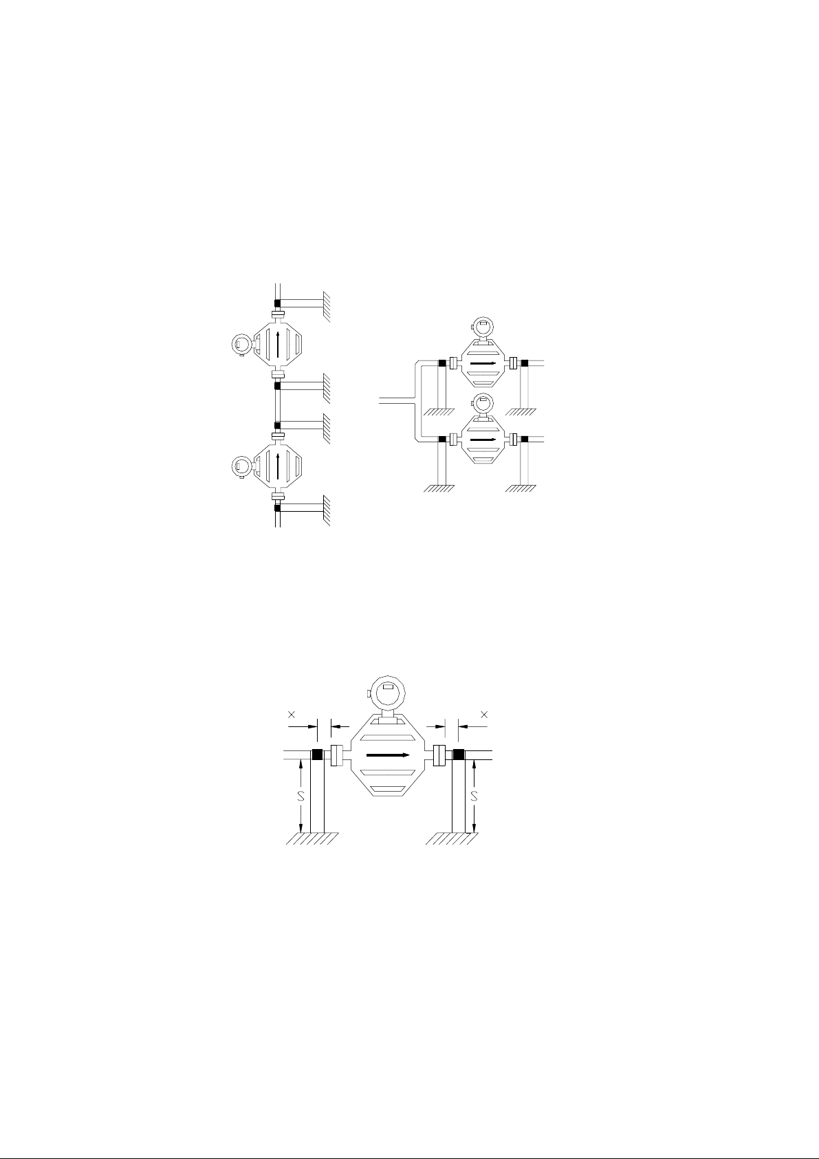
De-coupled pairs of Tr ansducer s
Transducers of the same size (or operating frequencies within 3 Hz) should not be installed in
close proximity (< 4 L) in the same pipeline or connected via a mutual mount ing frame unless
they have been specially frequency de-coupled by the manufacturer (see Fig. 11).
The first 5 digit s of t he RB (shown on the Data Plate and on the Calibrati on Certi f icate) give
the operating frequency of the transducer with water.
Fig. 11 Mounting of matched transducers serial or parallel
2.2.2 Requirement s of t he Pi pi ng System
Fixing
The mounting supports must be kept as short and as rigid as pract i cal to prevent excitation of
resonant vibrations by the transducer (see Fig. 12). Addit ional cross bracing is necessary
when the maximum support length s
is exceeded (see Fig. 13).
m
Fig. 12 Mount ing with rigid suppor ts
12
Page 13
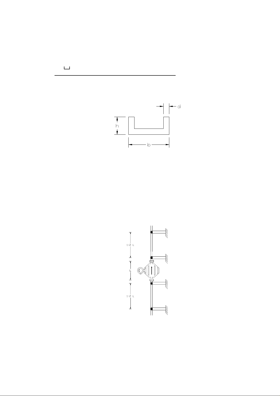
As an example the table indicates maximum support length for U-shape profile and the various
transducer sizes.
Dimensions and maximum lengths s
of U-shape supports. The chosen material dimensions
m
are examples for adjusting support dimensions to transducer size.
profile
b
mm (in)hmm (in)dmm (in)
s
m
mm (in)
e.g. for
60 P
300 P
800 P
1500 P
60 (2.4)
80 (3.1)
120 (4.7)
160 (6.3)
30 (1.2)
45 (1.8)
55 (2.2)
65 (2.6)
6 (.24)
6 (.24)
7 (.28)
7.5 (.30)
1260 (49.6)
1490 (58.7)
1810 (71.3)
2090 (82.3)
Fig. 13 U-profile
The pipe clamp on the supports should have a large surface area contact with t he support and
process pipe. No rubber, plastic or other material should be installed between the clamp and
process pipe. The transducer should be supported and clamped free of tension on either side
of the flanges as illustrated. The clamps should be equidistant and as close to the flanges as
possible.
Do not mount supports on f lang es or on the housing .
Process pipes on either side of the transducer should be axially aligned, and fl anges should be
parallel face to face within 0.4 mm (.016 in). the installat ion dimension (L) acr oss t he
transducer flanges must be mat ched to the process pipe flanges within ± 2 mm (.079 in).
For long pipe runs additi onal pipe supports must be installed 1 to 2 transducer lengths (L)
apart (fig. 14).
Fig. 14 Dist ance of a dditiona l supports
13
Page 14
Reduction in Process Pipe
Use standard reducing connectors on process pipes when they are larger than transducer
connection (fig. 15).
Fixing instructi ons mentioned previously must be foll owed.
Fig. 15 Use of reducing connectors
Flexible Hoses
Generally flexible hoses should be avoided. In applications where vibration is excessive,
flexible hoses can be used to de-couple the process from t he transducer.
Some applicati ons dem and t he use of flexible hoses and therefore the installation should
comply wit h t he diagr am (fig. 16) .
If in any doubt about t he use of flexible hoses contact KROHNE prior to instal l ation.
Fig. 16 Use of flexible hoses
Transport supports
not
Transport supports f itted to larger meters are
pipeline (fig. 17).
to be used for fixing the transducer in the
Fig. 17: Do not use t ransport supports for mounti ng
14
Page 15
Requirement for Zero Adjustment
A shut-off valve should be installed downstream of the transducer.
Tight shut-off is im por t ant ( f ig. 18).
Fig. 18 Shut-off valve downstream of the transducer
For best zero adjustment the meter can be installed in a by-pass arrangement as shown in the
diagram ( f ig. 19).
All peripheral devices can be active under operating conditi ons and t he process flow m ust not
be shut off.
Fig. 19 By-pass installation for best Zero Adjustment
2.2.3 Special rem ar ks on t he MFS 3000
In order to guarantee the perfect function of the CORIMASS transducer MFS 3000 (even after
poor transport condi t i ons) , the transducer is provided with a “Transport Safety Device”. The
“Transport Safety Device” must be inactive for operation and active for t r anspor t ation as
follows:
Comm issioning:
Before commissioning, the “Transport Safety Device” must be made
recessed Allen Screw (on reverse side of the instrument) anti - clockwise against the
mechanical stop wit h a 6 mm All en Key. In the case of the MFS 3000 - 30E two “Transport
Safety Devices” are used, and both must be made inactive prior to commissioning
(see Fig. 20).
inactive
by turning the
15
Page 16
Transport:
active
Before packing the unit for transport t he “Transport Safety Device(s)” m ust be m ade
turning clockwise against t he m echanical st op ( see Fig. 20).
Note: Models MFS 3000 - 0.3 E, 1.5 E, and 10 E are depicted above. Model MFS 3000 - 30 E
has two transport locks ( not shown) on t he sam e side of the instrument as the single transport
lock shown.
by
Fig. 20 Location “Transport Safety Device”
Flexible pipes or hoses can easily be connected at the permanently inst al led transducer.
When instal ling in a horizontal posi t ion, the transducer can also be turned 90° and mounted
flat, as shown in Figure 21.
Fig. 21: Mounting variations for horizontal installation
16
Page 17

Caution:
If the M FS 3000 tr ansducer s ar e oper at ed in the flow directi on cont r ar y to that i ndicated
by the arrow on the rating plate, the transducer constant G K may change by 0.15%
3. Electrical inst al lation
3.1 Location and connecting cabl es
Location
Do not expose the compact flow meter to direct sunlight. Inst all a sunshade if necessary.
Connecting cables
To conform t o protection category requirements, observe the following recommendations:
– Fit blanki ng plug PG 16 or 1/2” NPT and apply sealant to unused cable entries.
– Do not kink cables directly at cable entries.
– Provide water drip point ( U bend in cable).
– Do not connect rigid conduit t o cable entries. Use flexible conduit when required. Make
sure conduit drains away from connection to converter and transducer.
– If cables are a tight f it, enlarge inside diameter of cabl e gland by rem oving the appropriate
ring(s) fr om the seal.
3.2 Connection to power
Please ensure that the informat ion about power given on the
dataplate corresponds to the locally avai l able mains voltage.
– Note informat ion given on the instrument dataplat e (volt age, fr equency)!
– Electri cal connect ion in conformi ty with IEC 364 or equivalent national standard.
– Special regulations apply t o i nst allation in hazardous areas. Please refer to separate "Ex"
installation instructions.
– The PE protective ground conductor must be connected to the separate U-clamp
terminal i n the terminal box of the signal converter.
– Do not cross or loop the cables in t he t er minal box of t he signal converter. Use separate
(PG or NPT) cable glands for power and output cables.
– Ensure that the screw thread of the round cover on the term i nal box is well greased at
all times.
NOTE: The grease used must be non-corrosive to alumi nium; typi cally it m ust be resinand acid-free.
– Protect sealing ring from damage.
– See Figure 22 for the arrangement of power connections.
17
Page 18
5 6 4 4.1 4.2 11 12
}
Output
Connections
see Section 3.3
Figure 22: Power and signal connections for MFC 081 K / F
3.3 Inputs and outputs
The table below shows the input/output connection for the converter. The exact configuration
depends on which optional output m odul es were fitted in the factor y. The output opt ions listed
include presently available and planned options. See Figure 22 for the arrangement of
converter connections.
specifically ordered.
Table of input/ out put connections
No. Option 1
(Current, pulse, alarm
and input )
5 Common ( - ) Common ( - ) Current output 1 (-)
6 Current output (+) Current output 1 (+) Current output 1 (+)
}
N L AC
- + DC
PE
Option 1 is nor mally supplied unless one of the other options i s
Option 2
(2 current,NGI)
*
Option 3
(2 current,GI)
**
4 Control input Control input. Current output 2 (-)
4.1 Pulse output Current output 2 (+) Current output 2 (+)
4.2 Alarm output ( active) Alarm output (passive) not used
* The inputs/outputs share a common signal ground which i s galvanically isolated from
ground (PE).
** Both current output s ar e galvani cal ly isolated from ground and each other.
For the standard converter, the pulse output is passive and requires an external voltage source
for operation. In addition, the signal may need protection from external electrical i nt erference.
The use of screened cables and a filter capacitor next to any counter is recomm ended. (Fig.
23)
It is possibl e to connect the pulse output without using an external voltage supply. However to
do this the function of the alarm output must be sacrificed. (Fig. 24) .
If the alarm out put is used to power the pulse signal, then the following settings
in the menus.
(i) Fct. 3.5.1 ALARM FUNCTI ON must be set to OFF
(ii) Fct . 3.5.2 ALARM ACTI VE LEVEL must be set to ACTIVE LOW.
18
must
be made
Page 19

ext (Max. 24 V DC
)
V
ext
R
4.2
4.1
4
6
5
Pulse Output
Common
Screened Cable
OV
Fig. 23: Connection with external voltage source
(> 800 ohm)
ext
R
4.2
4.1
4
6
5
Pulse Output
Common
Screened Cable
OV
Fig. 24: Connection using converter internal voltage source
Additional i nput /output options
ext
V
ext >
R
0.15
88888888
+
COUNTER
_
ext
C
(10 - 100nF if required)
88888888
+
COUNTER
_
ext
C
(10 - 100nF if required)
No. Option 4
(2 current,
pulse and
input)
5 Common
(-)
6 Current
output (+)
4 Current
output 2 (+)
4.1 Control
Input
4.2 Pulse
Output
Option 5
(3 current
and
pulse)
Common
(-)
Current
output 1 (+)
Current
output 2 (+)
Current
output 3
(+)
Pulse
output
Option 6
(3 current
and
input)
Common
(-)
Current
output 1 (+)
Current
output 2 (+)
Current
output 3
(+)
Control
Input
Option 7
(3 current
and
alarm
Common
(-)
Current
output 1 (+)
Current
output 2 (+)
Current
output 3
(+)
Alarm
output
(passive)
* Refer to separate RS 485 manual
** Refer to separate manual f or t hi s out put opt ion.
*
Option B
(Current
and
RS485)
Option C
(1 Current,
1 Dual
phase pulse
output and
input)
Common
(-)
Current
output 1 (+)
Common
(-)
Current
output 1 (+)
TX/RX Control
Input
TX/RX Pulse
Output A
+5V Pulse
Output B
**
19
Page 20

4. Start-up
4.1 Factory Set Parameter s
The mass flowmeter leaves the factory ready to be used. All process data has been
programmed according to the customer order. See factory program ming sheet delivered with
the flowmeter.
When no process details were supplied at the time of order, the mass flowmeter is
programmed to a standard default set of values and functions.
The current and pulse outputs treat all flows as posi t i ve. The actual flow and quantity is
thereby measured independent of the flow direction. The indicator will indicate a “ – “ or “ + “
in front of the flow rate.
These factory-set settings for current and pulse may cause an error under the following
conditions: When the pump is stopped and a reverse flow is present, which is lar ger than the
low flow cut-of f or when total i zing shoul d be indi cat ed for bot h f low directions.
To avoid these possible problems:
a) Set flow mode (Fct. 3.1. 8) t o eit her fl ow > 0 or Flow < 0, so that back flows are ignor ed.
or
b) Increase Low Flow cut-off (Fct. 3.1.7) so that small back flows are ignored.
or
c) Set the alarm output (Fct. 3. 5. 1) to DIRECTION so that external equipment can
differentiate between positive and negative flows.
4.2 Initial St art-up
• Please check that the power supply corresponds to the informati on suppl ied on the data
plate.
• Switch on t he power supply.
• On swi t ch- on, t he signal converter fi r st car r ies out a self-test. The following sequence is
displayed:
TEST
10 E PX.XX
Primary Head Software Version
STARTUP
Mass flow will be displayed following a brief settling phase for the primar y head.
A minimum warm-up time of 30 minutes is recom mended to ensure
stable measurement operation.
• For st able and accurate mass flow results the following should be checked:
a) The quality of the mechanical i nst al lation. See Sect. 2.
b) A good zero point calibration should be done. See Sect. 4.4. Further information
regarding zero point calibration can be found in Sect. 5.
20
Page 21

4.3 Installation factor
The extensive self-diagnosis functions of t he MFM 2081 and MFM 3081 also include a socalled installat ion factor. This f act or indicates whether the flow meter has been correctly
installed in the pipeline. The install at i on factor should be checked during the initial start - up
phase. The installation fact or can be checked by way of the keystroke combination described
in Section 5.
If correctly installed, the value of the installation factor when the primary head is full of water
should be as per the table below. If the figure is higher, the specified accuracy of the flow
meter cannot be guaranteed. Please check the installation again on t he basis of t he installation
inform at i on ( Sect. 2) . I f necessary adjust cl amping with the meter displ ayi ng t he installation
factor to obtain optimum performance.
Primary Type Installation
Factor
MFM 2081 K/ F < 50
MFM 2081 K/ F
< 100
Ex
MFM 3081 K/ F < 20
MFM 3081 K/ F
< 60
Ex
4.4 Zero point adjust ment
After installation adjust the zero point. To do this, the primary head must be completely filled
with the liquid pr oduct wi t hout gas or air inclusions. This is best obtained by allowing t he
liquid product t o flow through the primary head for approx. 2 minutes at a throughput rate of
greater than 50% of rated flow. Subsequently ensure that flow comes to a complete stop in the
primar y head (see fig 10, Section 2.2. 2) f or setting the zero without interruption to pr oduct
flow, use a bypass setup as shown in fig. 11 (Section 2.2. 2) .
Now initiate zero adjustment from measuring mode as described in Section 6.1.
Under certain conditions, it may not be possible to adjust the zero point:
– If the medium is in motion. Shut-off valves not tightly closed.
– If there are gaseous inclusions in the primary head. Flush t he primary head and repeat the
calibration.
– If resonant oscillations of the piping are interfering with the primary head. Check the
clamping of the instrument.
– If there are active warning(s) in the status message list. ( See section 5.6)
In such cases, the zero point adjustment procedure is automatically aborted and the following
message is displayed for a short ti me:
ZERO.ERROR
Then the converter returns to the start of the Zero Set function 1.1.1:
Further information on zero point adjustment is given in Section 5.
The CORIMASS MFM 2081 and MFM 3081 are ready to operate after zero has been adjusted.
All param eters have been factory-set in keeping with the data specified in your order. Detailed
inform at i on for further setting of the signal converter will be found in Part B of the operating
instructions.
21
Page 22
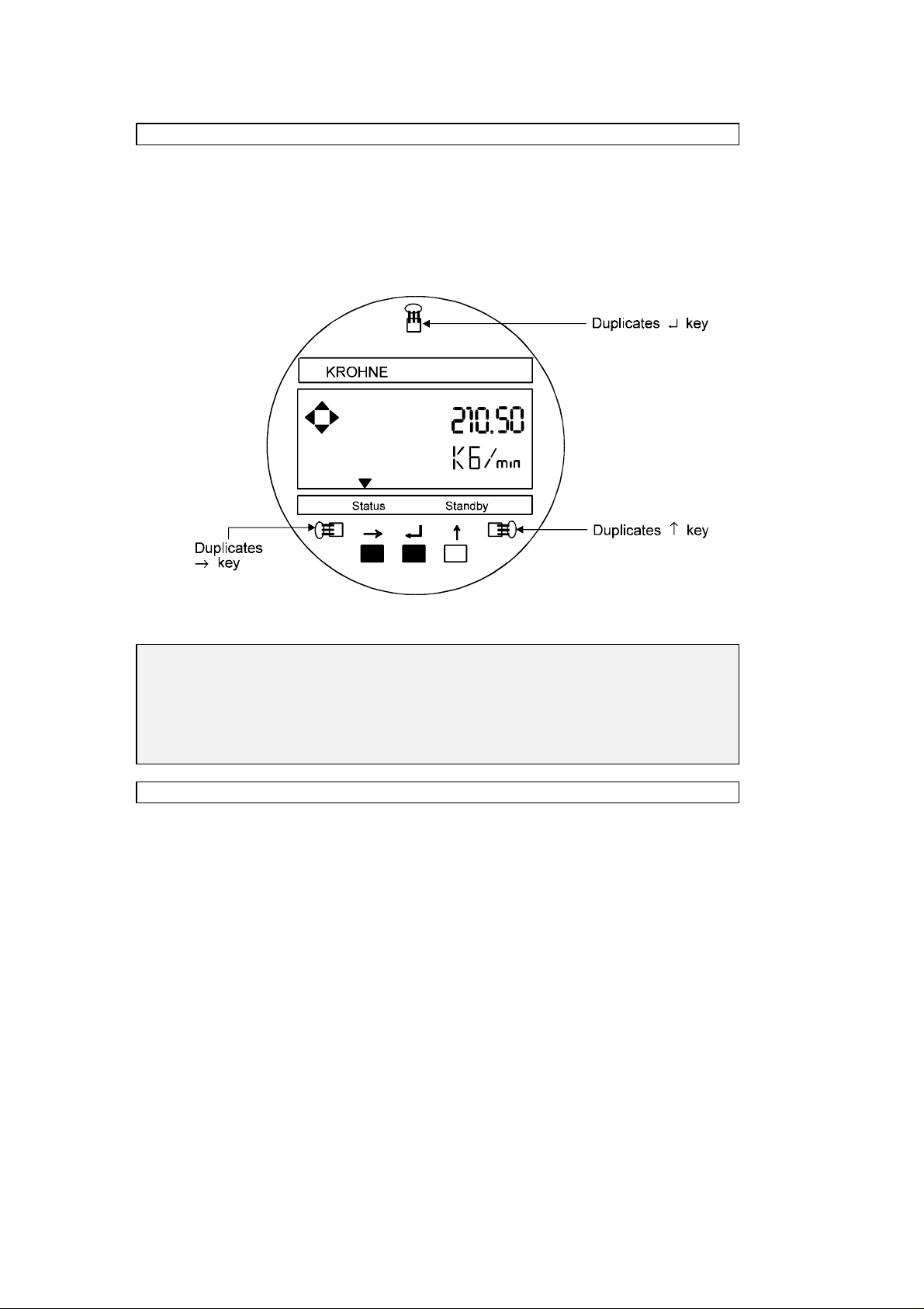
4.5 Programming the converter wit h a bar magnet
• The converter can be programm ed by means of the m agnetic sensors mounted on the
face plate without removing t he front lid (see Fig. 25).
• To do this, a bar magnet (standar d supply) is used to activate the sensors by holding the
magnet close to the glass window of the housing lid.
• These sensors then duplicate the functions of the push buttons.
MFC 081
Fig. 25: Magnetic sensor locations on MFC 081 face plate
CAUTION:
For previous software versions P2.14 to P2.18, the maximum connecting cable length between
transducer (primary head) and MFC 081 F signal converter is 5 meters (16.25 feet). Previous
software version R2.18 and this version, P2. 20, permit longer cable lengths up to 100 meters
(328 feet), unless limi t ed by CE and/or hazardous location requirements. Also note that
software versions R2.18 and P2.20 have hardware changes in the MFC 081 converter, as
compared to converters incorporati ng earlier software versions.
4.6 Installat i on of the Converter MFC 081 F
In the compact version the converter is mount ed directly onto the transducer.
In the separate version MFC 081 F (remote mounted) it has to be noticed that t he readability
of the display depends on the lighting and the viewing angle. It should, t herefore, be installed
at eye-level and in good lighting conditi ons but not exposed to direct sunlight. Refer to Section
D for dimensions of t he MFC 081 converter.
Because of the rotatable housing it is easy to connect the wires for the power supply and the
input and outputs.
The installation of t he power supply wiring must compl y wi t h local Electrical Codes.
22
Page 23
4.7 Connection of Rem ot e Mounted Version
The BTS 12L signal cable is specifically for CORIMASS remote mount ed versions and must be
used to assure proper operation. This cable must be connected as described below. The color
of the outer sheath is black for all st andar d instruments. For instruments located in hazardous
areas, the cable sheath may be blue or black depending upon the specific electrical
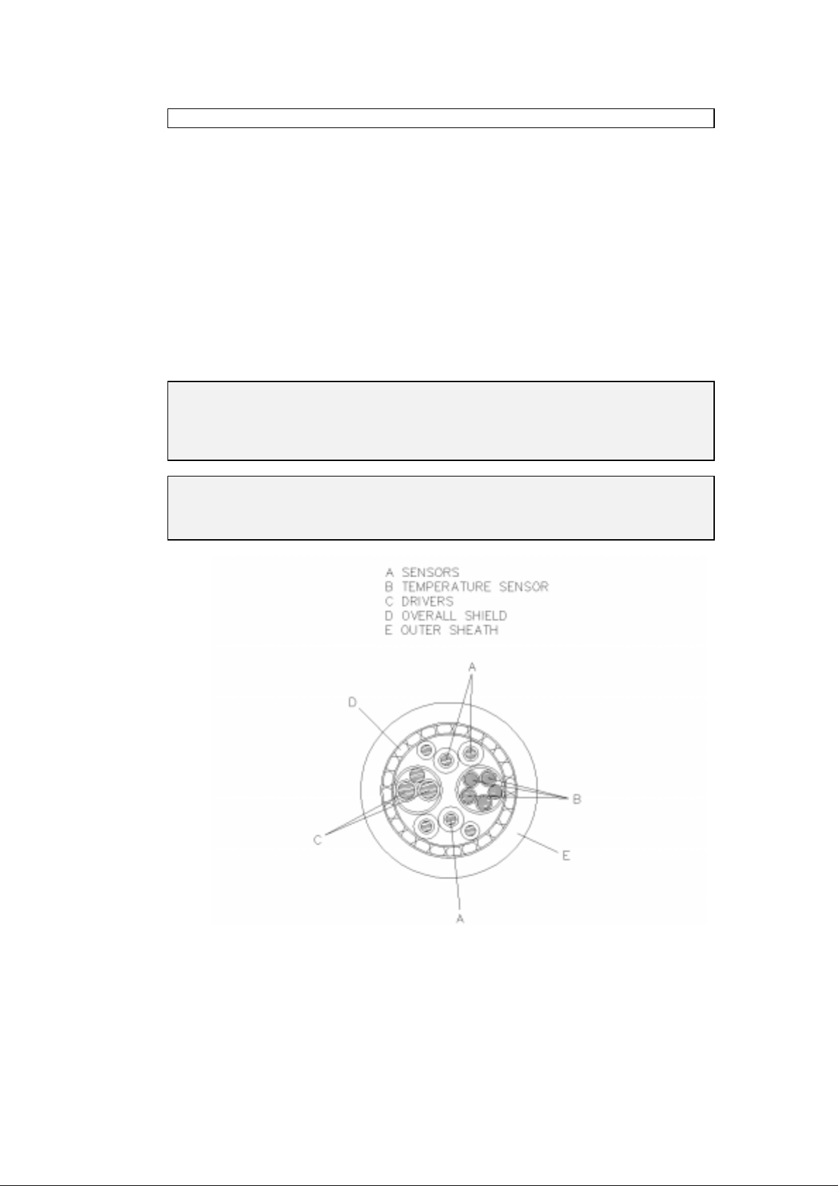
classificat i on and the approval agency (PTB, FM, etc.). Figure 26 shows a cross-section of the
BTS 12 L cable. Please note that not all conductors are used in the MFM 2081 / 3081 F
application. Figures 27 through 30 depict the connection of this cabl e to the transducer and
converter.
Minimum bend radius of cable should be 24 cm (10 inches). The cable must be fixed carefully
in the vicinity of t he transducer to avoi d r esonant vibr at ions of the cable. Also, all screws in
the terminal boxes and covers should be securely fastened.
Maximum cable length is dependant upon software version and may also be li mited by CE
requirements or local requirements for hazardous locat ions.
CAUTION:
When blue cable is required for hazardous duty instal l at ions, it is an essential part of t he
approval. For other cables the hazardous duty protection appr oval is not vali d.
Furthermore the ground terminals located on the transducers should be connected to the
potential com pensator f or t he hazardous area.
CAUTION:
For applicati ons where CE approval is required, the supplied signal cabl e fit tings must be
properly install ed to provi de less than 1 m illiohm contact resistance between the cable overall
shield and the fitti ng body.
Fig. 26: BTS 12 L Signal cable cross-section
23
Page 24
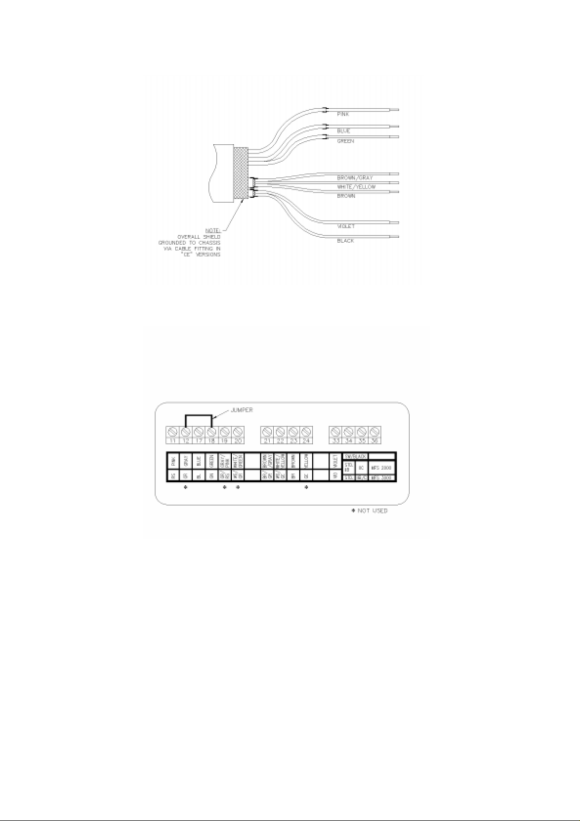
Note: On the transducer cable end individual shields are not connected and should not
protrude from under the shrink t ubing.
Fig. 27: Signal cable terminations - transducer end
For MFM 2081 F, the black wire should be connected to terminal 34 for standard and EEx ib II
B applications, or t o 35 for EEx ib II C applicati ons
For MFM 3081 F, the black wire should be connected to terminal 34 for standard applications,
or to termi nal 35 for EEx ib II C applicat ions
Fig. 28: Transducer terminal box connections
24
Page 25
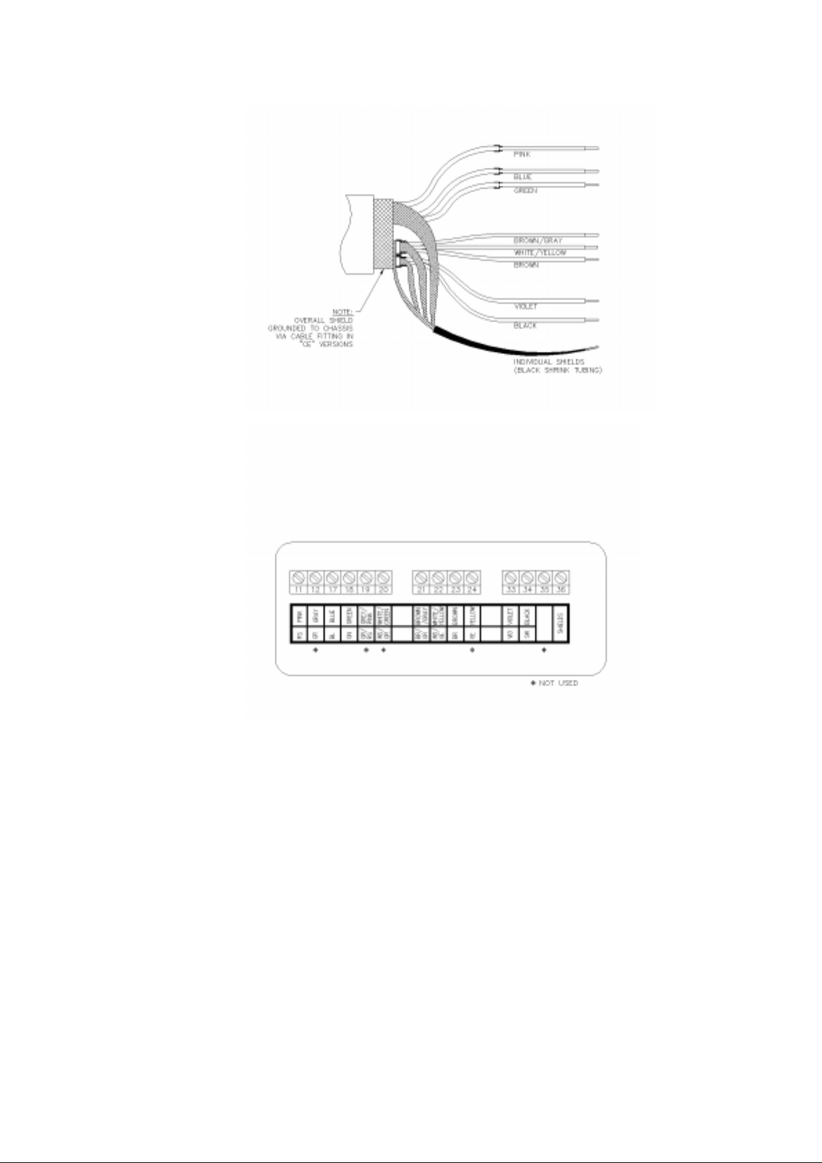
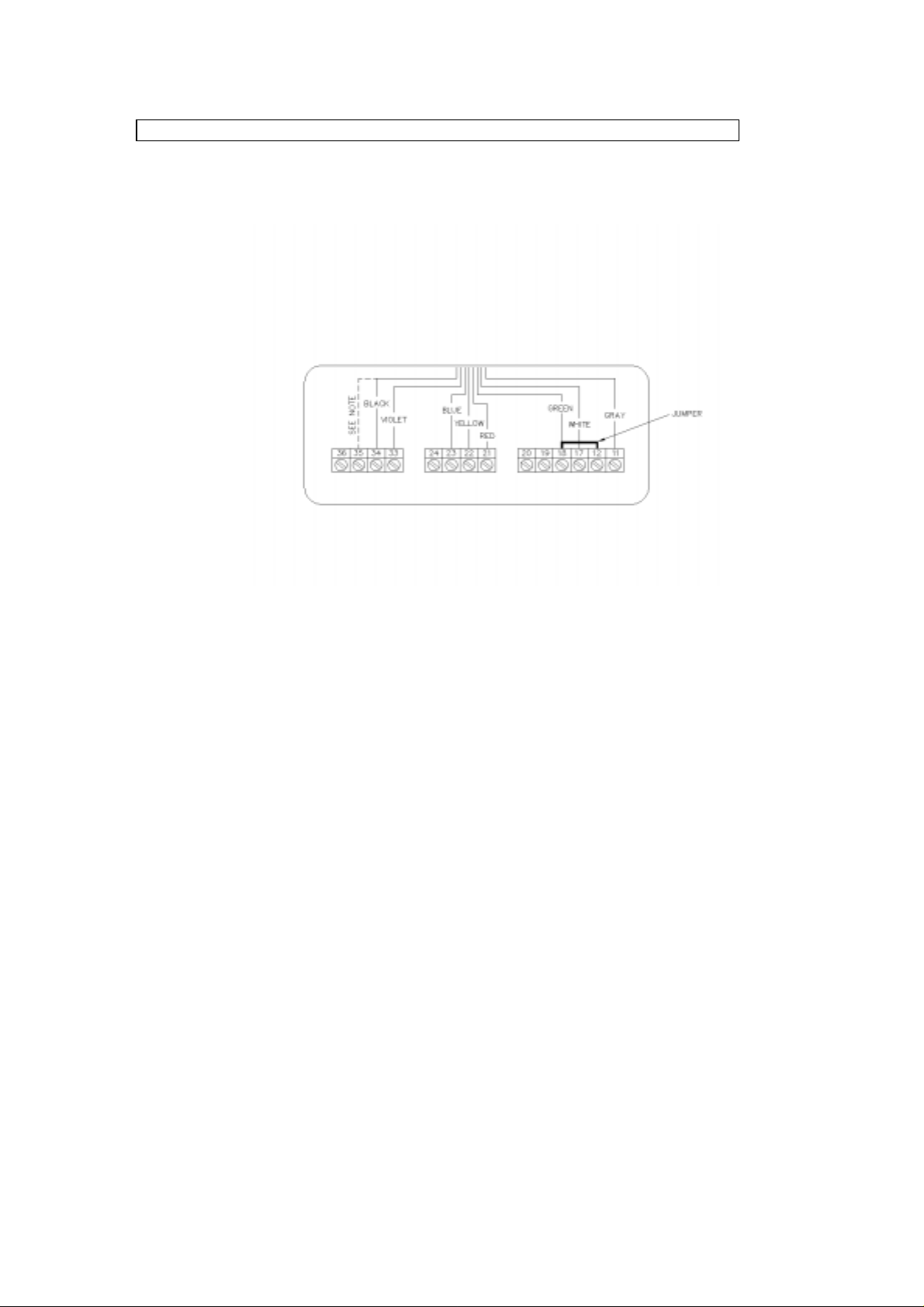
Fig. 29: Signal cable terminations - converter end
Fig. 30: Converter terminal box connections
25
Page 26

Designation of terminals in t he Convert er Ter minal Box:
11
Sensor A +
12
not connected
17
Sensor B +
18
Sensor B –, A –
19
not connected
20
not connected
21
Temperature Sensor V –
22
Temperature Sensor I +, V +
23
Temp. I –
24
not connected
33
Exciter +
34
Exciter –
36
Chassis Signal Shield
pink
blue
green
-
brown/grey
yellow/white
brown
violet
black
black (shrink)
FITTING O VERALL SHIELD
Designation of terminals in t he Transducer Ter minal Box:
11
12
17
18
19
20
Sensor A +
Sensor A Sensor B +
Sensor B –
not connected
not connected
pink
jumper to 18
blue
green / jumper to 12
-
-
21
Temperature Sensor V –
22
Temperature Sensor I +, V +
23
Temp. I –
24
not connected
33
Exciter +
(MFS 2000 - All)
(MFS 3000 - All)
34
Exciter –
(MFS 2000 - Standard and EEx ib II B)
(MFS 3000 - Standard)
35
Exciter –
(MFS 2000 - EEx ib II C)
(MFS 3000 - EEx ib II C)
FITTING O VERALL SHIELD
brown/grey
yellow/white
brown
violet
black
black (alternate)
26
Page 27

For applicait ons where CE approval is requir ed, the BTS 12 L cable is prepared by Krohne to
the required length, ready for installation. For non-CE appli cat ions, the cable provided may be
prepared only at the converter end to permit t he customer to more easily route the cable
during instal l at ion, and tailor the length as needed. In these cases, the transducer end of the
signal cable will need to be prepared by the customer using the parts in the kit provided with
the cable. The kit contains the following items:
Connector Sleeves:
(2) - 1 mm
(6) - 0.5 mm
2
for violet and black wir e ends
2
for remaining wire ends
Shrink Tubes:
(1) - 35 m m long, φ12 mm (A)
(2) - 15 m m long, φ 6 mm (B)
(3) - 15 m m long, φ 3 mm (C)
Connector sleeves are to be crimped on to the wire ends indicated and shrink tubes A, B, and
C are to be installed as shown in Figure 31. Unused conductors should be cut back cleanly to
avoid interference with the active conductors and shields.
Figure 31: Stripping lengths and shrink tube locations for BTS 12 L signal cable transducer end
27
Page 28
4.8 Connection diagram of compact versi on
The connection converter - transducer of the compact version will be carried out by the
manufacturer. A reconnection is onl y r equired in the case of a defective cable between
terminals and electronics module. You can see the connection of the converter cable in the
terminal box at Fi gur e 32.
Note:
MFM 2081 K
Black to 34 for Standard and EEx ib II B
Black to 35 for EEx ib II C
MFM 3081 K
Black to 34 for Standard
Black to 35 for EEx ib II C
Fig. 32: Connection compact version
28
Page 29
Part B MFC 081 Signal Convert er - Software Version P2.20
5. Operation of t he Si gnal conver t er
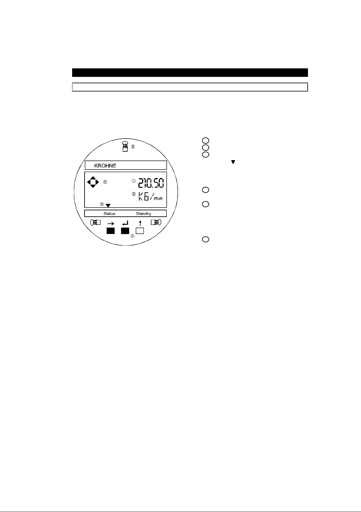
5.1 Operating and check el ements
The o perating el ements a re ac cessible af ter rem ovi ng the cover o f the electroni cs section
using the special wrench. The converter is also programm abl e with magnetic sensors and a
bar magnet without r em ovi ng t he covers of the electronic housing.
Caution: Do not damage the screw thread and the gasket, never allow dirt to accumulate,
and make sure they are well greased at all times.
1 Display 1st (top) line.
2 Display 2nd (middle) line.
3 Display 3rd (bottom) line,
MFC 081
arrows ( ) to identify the
state of the signal converter:
-
4 Keys for operator control of
the signal converter.
5 Magnetic sensors to set the
converter by means of a
handheld bar magnet without
opening the housing. Function
of sensors same as keys 4 .
6 Compass field, signals
actuation of a key.
message indicator
Status
Standby
mode.
The operator control concept consists of three levels (horizontal). See next page.
Setting level: This level is divided into three main menus:
Fct. 1.0 OPERATION: This menu contains only the m ost
import ant par ameters and functions of Menu 3 (instal l ) t o allow
rapid changes to be made during the measurement m ode.
Fct. 2.0 TEST: Test menu for checking the signal converter
(displays, outputs, measuring range), and the primary (transducer)
operation.
Fct. 3.0 INSTALL: All f l ow measurement- and flowmeter-specific
parameters and functions can be set in this menu.
Paramete r check l evel: Fct. 4.0 PARAM.ERROR: This level is not selectable.
After exiting from the “Setting l evel”, the signal converter checks
new data for plausibility. If an error is detected, the signal
converter indicates PARAM.ERROR in Fct. 4.0. In this menu, all
functions can be scanned and those changed that are not
“plausible”.
Reset/acknowledge This menu has two tasks and is selected via Entry Code 2
level (Quit): ( ↵ ↑ → )
1) Resetting of totalizer, provided that resetting is enabled under
Fct. 3.8. 5 ENABL. RESET, input YES.
2) Status message and acknowledgement (Quit) m essages that
have occurred since the last acknowledgement are indicated
in a list. After elimination of the cause(s) and
acknowledgement, these messages are deleted from the list.
29
Page 30
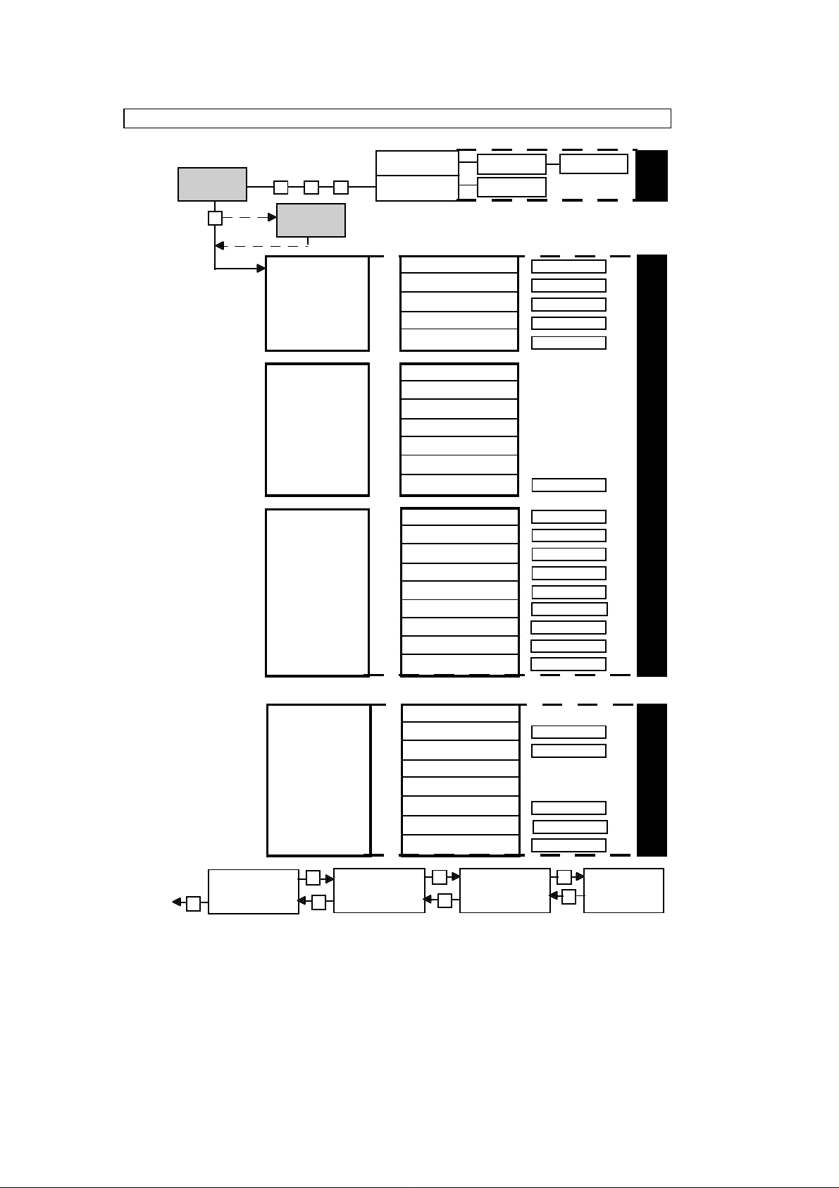
5.2 Krohne Operating Concept
↵
→
↵↵↵
↵
→
→
↵
↵
Measur ing Mode
210.50
kg/min
Split function s
of keys between
main and
submen us .
The blink ing
part of the
display (cursor)
that may be
changed is
in
bold
When in
RESET/QUIT
and progr amming
modes, outputs
remain active,
measuring
normally, except
in 2.0 TEST menu
when output is
being tes ted, and
when zeroing
flowm eter - 3.1 .1
and 1.1.1 MEAS.VALUE
Code 2
Code 1
- - - - - - -
.0 OPERATION
1
.0 TEST
2
.0 INSTALL
3
STATUS.LIST.
RESET TOTAL
When th is display appe ars, press entry code 1.
See Fct. 3.8.2 and 3.8.3. Factory setting:
1.1.0 BASIS.PARAM.
1.2.0 DISPLAY
1.3.0 CURRENT OUT I
1.4.0 PULS.OUTP.P
1.5.0 ALARM OUT A
2.1 TEST DISP
2.2 TEST I
2.3 TEST P
2.4 TEST A
2.5 TEST INP.E
2.6 TEST TEMP
2.7.0 TEST.PRIMRY
3.1.0 BASIS.PARAM
3.2.0 DISPLAY
3.3.0 CURRENT.OUT I
3.4.0 PULS.OUTP.P
3.5.0 ALARM.OUT.A
3.6.0 CTRL. INP.E
3.7.0 SYS.CTRL.S
3.8.0 USER DATA
3.9.0 TUBE PARAMS
Error List
RESET YES
RESET NO
1.1.1 - 1.1.
1.2.1 - 1.2.
1.3.1 - 1.3.
1.4.1 - 1.4.
1.5.1 - 1.5.
2.7.1 - 2.7.
3.1.1 - 3.1.
3.2.1 - 3.2.
3.3.1 - 3.3.
3.4.1 - 3.4.
3.5.1 - 3.5.
3.6.1 - 3.6.
3.7.1 - 3.7.
3.8.1 - 3.8.
3.9.1 - 3.9.
QUIT YES
QUIT NO
↑↑↑
4
7
3
3
3
4
8
8
4
4
4
2
4
8
11
RESET /
QUIT
PROGRAMMING LEVEL
Param. Check
and retu r n t o
measurement
mode
30
.0 PARAM.ERROR
4
Main Menu
Select with Key
↑
Submenu
Select with Key
↑
4.1 not used
4.2.0 CURRENT.OUT. I
4.3.0 ZERO SET
4.4 not used
4.5 not used
4.6.0 PULS.OUTP.P
4.7.0 PROC.ALARM
4.8.0 SYSTEM.CTRL
Function
Select with Key
↑
4.2.1 - 4.2.
4.3.1 - 4.3.
4.6.1 - 4.6.
4.7.1 - 4.7.
4.8.1 - 4.8.
2
2
2
2
2
Data Input
with Keys
LEVEL
PARAMETER CHECK
↑
Page 31

5.3 Key functions
Before pressing any keys on the MFC 081 converter, it should be noted that outputs rem ain in
the Measurement Mode (outputs are actively measuring) even when the converter is placed in
the Programm ing Mode with the following exceptions:
− when in the TEST menu (2.0) and act ual ly testing an output.
− after having m odi fied and accepted a parameter which will cause a given output to change,
eg. changing the range.
− when zeroing (1.1.1 and 3. 1.1) using the MEASURE. VALUE parameter at which time t he
flow must be shut off. The output associated with the flow rate defaults to its minimum
range value (0 or 4 mA, whichever is programmed) during zeroing. When using SET
VALUE, the output remains active, changing onl y by t he SET VALUE once it is accepted.
Function of the keys
Cursor
The location of the cursor on the display is i ndicated by flashing characters. This
could be a single digit when entering number; num eric si gn ( + or - ) ; measurement
units (g,kg, t etc.) ; or any ot her text field. Thr oughout this manual the location of the
cursor, in programming examples, will be indicated by parentheses ( ) around the
flashing characters.
↑ Select or Up Key. This key changes the field/digit under the cursor.
- Digit: Increase value by 1 for each key press. (0 follows 9).
- Dec. pt. Move decimal point. 0000( . ) 0000 changes to 00000(.) 000
- Menu Increase menu number by 1. i.e. Fct. 1.(1).0 changes to
Fct. 1.(2).0
When the menu number reaches its maximum the next ↑ changes
the number to 1. i.e. Fct 1.(5).0 changes to Fct 1.(1).0
- Text Change text field. i.e. “YES” to “NO” or “g” to “kg” to “ t” etc.
- Sign Toggle “+” to “-”
→
Cursor or Right Key. This key moves the cursor onto the next field to be edited.
(usually the next on the right).
- Number Move cursor from 12(3).50 to 123( . ) 50 t o 123. ( 5) 0
- Text Move to next field. i.e. (kg)/min to kg/(min)
- Menu Move to next menu column: i.e. from Fct 1.(2).0 to Fct. 1.2.(1)
or
if the cursor is already in the rightmost column: invoke that menu
function. i.e. from Fct. 1.2.(1) press → to edit MASS FLO W
format.
↵ Accept or Enter Key.
-Within a
Accept changes (if any) and exit the function.
function
-Menu Move cursor to the next column on the left.
i.e. from Fct. 1.2.(1) back to Fct. 1.(2).0
If the cursor is already in the leftmost column then ↵ exits the
menus. See next box: “To terminate” .
Note:
If numerical values are set that are outside the permissibl e input r ange, the displ ay
shows the min. or max. . acceptable value. After pressing the ↵ the number may be
corrected.
31
Page 32

5.3.1 How to enter programming mode
To start:
Display Comments
→ Press Fct. 1.0
If this appears, see previous box: “Function of the keys ” .
Operation
or
CodE 1
---------
If this appears on the display, set the 9-keystroke Entry
CodE 1 .
Factory setting: → → → ↵ ↵ ↵ ↑ ↑ ↑
1st- 8thplace
(key)
9th place
(key)
CodE 1
∗∗∗∗∗∗∗∗-
Fct. 1.0
Operation
CodE 1
(9 alpha
Each keystroke acknowledged by " ∗ " in display.
If this appears, see box: “Function of the keys ” on previous
page.
A wrong Entry CodE 1 was keyed in. Press any key and set
the correct 9-keystroke
characters)
5.3.2 How to terminate Programming mode
To termi nat e :
Press ↵ 1-3
times
↵ + 12.345
Fct (1).0
OPERATOR
kg/min
Press ↵ 1-3 times until t he cursor i s under the extreme
left menu column. (Fct. 1.0 , 2. 0 or 3. 0)
If no changes have been made to the system’s configuration return directly to the measurement mode.
or
(ACCEPT YES) Changes have been detected. Press ↵ to accept these
changes.
or
↑
(ACCEPT NO)
Press ↵ to reject changes and return directly to
measurement mode.
or
↑
(GO BACK)
Press ↵ to return to the menus, Fct. 1.(0) to make
further changes
↵ PARAM.CHECK Assuming ACCEPT YES was select ed,
the system now checks the new setting for errors.
After 1-2 sec. + 12.345
No errors detected. Return to measurement mode.
kg/min
or
Fct. (4).0
PARAM.ERROR
Errors were detected. The sub-menus of 4.0 will guide
the operator to those functions where problems have
been identified.
32
Page 33

Examples
The cursor (flashing par t of display) has a grey background in the foll owi ng exampl es:
To start programming
Measurement mode Programming mode
13.571
m3 / h r OPERAT I ON
PLEASE NOTE: When “yes” is set under Fct. 3.8.2 ENTRY CODE, the following will
appear in the display after pressing the → key:
CodE 1 - - - - - - - - -.
The 9-stroke entry code must now be entered.
Factory setting: → → → ↵ ↵ ↵ ↑ ↑ ↑.
Each keystroke is acknowledged by an “ ∗ “ in the display.
To termi nat e pr ogr amming
Press ↵ key repeatedly until one of the following m enus are displayed:
Fct. 1.0 OPERATION, Fct. 2.0 TEST or Fct. 3.0 I NSTALL
Fct. 3. 0
INSTALL. A C C E P T. Y E S
→
Press ↵key
↵
To accept the new paramet er s
Press ↵ to confirm.
“PARAM.CHECK” will appear in the display.
Fct. 1. 0
The measuring mode will continue after a few
seconds with the new parameters, when no
errors are detected.
When an error is detected the display will
indicate “Fct. 4.0 PARAM.ERROR”. The
error parameters can be called up in this
menu and corrected.
New parameters not t o be accepted
When the new parameters are not to be
accepted, the following keystrokes should be
executed: Press ↑ key. The display will
show “ACCEPT NO”. When the ↵ key is
then pressed, the instrument will return to the
measurement mode using the old
parameters.
33
Page 34

To change numeric val ues
Increase numeric value
210. 50
kg/mi n kg/mi n
To move the cursor (flashing digi t )
↑
210.60
To move to the right
210. 60
kg/mi n kg/mi n
To move the decimal point
→
210.6 0
To move to the right
21.060
kg/mi n kg/mi n
To change the text
M A S S F L O W D E N S I T Y
To change the units
↑
Select next text
↑
210. 60
Numeric values automat ically converted
Select new unit
210. 60
g/min k g/min
↑
Alternative time unit
210. 60
k g/min kg/m i n
To change from numeric values back to text
→
Alternative engineering units
210. 60
kg/mi n k g/min
Return to function display
10.3
Sec T IMECONST.
→
↵
0.21060
210.60
210.60
F c t. 1. 1. 3
34
Page 35

5.4 Table of programmable f unct ions
Fct. No. Text Description and settings
1.0 OPERATION Main menu 1. 0 Operation
1.1.0 BASIS.PARAM Submenu 1.1.0 Base data
1.1.1 ZERO SET Zero adjustm ent . See Fct. 3.1.1
1.1.2 L.F. CUTOFF Low flow cutoff. See Fct. 3.1.2
1.1.3 TIME CONST. Signal converter time const ant . See Fct. 3.1.3
1.1.4 STANDBY Switching between measur ing operation
and standby. See Fct. 3.1.4
1.2.0 DISPLAY Submenu 1.2.0 Displ a y
1.2.1 CYCL.DISP Switching between steady display and cyclic displ ay
1.2.2 STATUS MSG Select s which st at us messages should be displayed
1.2.3 MASS FLOW Unit for mass flow. See Fct. 3.2.3
1.2.4 MASS TOTAL Unit for mass total. See Fct. 3.2.4
1.2.5 DENSITY Unit for density. see Fct. 3.2.5
1.2.6 TEMPERAT Uni t f or t emperature. see Fct. 3.2.6
1.2.7 VOLUME.FLOW Unit for volume flow. See Fct. 3.2.7
1.2.8 VOLUME.TOTAL Unit for volume total. See Fct. 3.2.8
1.2.9 CONC.MEAS Parameters for concentration m easur ement.
See separate concentration measurement instruction
manual
1.2.10 CONC.MEAS See 1.2.9
1.2.11 CONC.MEAS See 1.2.9
1.3.0 CUR.OUTP. I Submenu 1.3. 0 Cur r ent output I.
1.3.1 FUNCTION I Function current out put I. see Fct. 3.3.1
1.3.2 MIN.VALUE* Mini mum range f or cur rent output I see Fct. 3.3.3
1.3.3 MAX.VALUE
*
Maximum range for cur r ent output I see Fct. 3.3.4
1.4.0 PULS.OUTP. P Submenu 1. 4. 0 Pul se, frequency output P. see Fct. 3.4.0
1.4.1 FUNCTION P Select. Parameter to be totalized
1.4.2 PULSE/MASS * Select. Pulse per unit
1.4.3 PULSE W IDTH * Select pulse width in milliseconds
1.5.0 ALARM.OUT.A Submenu 1.5.0 Process alarm output A. see Fct. 3.5.0
1.5.1 FUNCTION A Select alarm function. See Fct. 3.5.1
1.5.2 ACTIV.LEVEL Select. act i ve hi gh or low. See Fct. 3.5.2
*
Exact display de pends on selected function. See sub-menu 3.3.0
35
Page 36

Fct. No. Text Descri pt i on and settings
2.0 TEST Main Menu 2.0. Test functions
2.1 TEST DISP. Carry out display test.
Start with the key → (Duration of test approx. 30 sec.).
Stop test at any time with the ↵ key.
2.2 TEST I Test current out put I
* SURE (NO). Use the ↑ key to select YES, then press ↵.
* 0 mA will be output from the converter. Use the ↑ key
to select test currents from the list below.
0 mA, 2 m A, 4 mA, 10 mA, 16mA, 20 mA, 22 mA.
To exit test mode, press the ↵ key at any time.
2.3 TEST P Test frequency output P
* SURE (NO). Use the ↑ key to select YES ,then
press ↵ key.
2.3.1 FREQUENCY * LEVEL LOW 0 volt DC level will be output from the
converter.
Use the ↑ key to select test signals from t he list below.
* LEVEL HIGH ( + V v o lts dc)
* 1 Hz * 100 Hz
* 10 Hz *1000 Hz
2.3.2 TEST PULSE * Test Pulse
Use the ↑ key to select desired pulse width from the list
below:
∗ 0.4 mSec ∗ 100.0 mSec
∗ 1.0 mSec ∗ 500.0 mSec
∗ 10.0 mSec
Then press ↵. The system now sends pulses of the
required width. To stop the test press ↵ twice.
2.4 TEST A Test alarm out put
* SURE (NO). Use the ↑ key to select YES, then
press ↵
* LEVEL LOW. 0 Volts is out pu t on the alarm terminal.
Press the ↑ key to switch output to:
* LEVEL HIGH . +2 4V d c is output o n the alarm termi n a l.
To exit test mode, press the ↵ key at any time.
2.5 TEST INP.E Test control input
The actual input level, HI or LO, and t he selected
functions are displayed see Fct. 3.6.1
End test by pressing the ↵ key.
2.6 TEST TEMP. Test t emperature
Start with the → key. The temperature in °C is displayed.
Use the ↑ key to display the temperature in °F.
End the test by pressing
↵ key
2.7.0 TEST.PRIMRY. Sub menu 2.7.0 Test primar y head values.
2.7.1 SENSOR A Monitor t he amplitudes of sensor A and B
2.7.2 SENSOR B as percentage of their max. value. ( 80% is i deal )
Start test with the → key. End the test with the ↵ key.
2.7.3 FREQUENCY Monitor the primary head frequency.
Start test with the → key. End the test with the ↵ key.
2.7.4 INSTAL.FACT. Monit or t he pr i mary head's drive level.
Start test with the → key. End test with the ↵ key.
36
Page 37

Fct. No. Text Descri pt i on and settings
3.0 INSTALL. Main menu 3.0 Installation
3.1.0 BASIS.PARAM Submenu 3.1.0 Base data
3.1.1 ZERO SET Zero adjustm ent .
Use the ↑ key to select between MEASURE.VAL.
and SET VALUE then press the ↵ key.
* MEAS.VALUE (ensure "ZERO" flow in the pip eline)
1) Select: CALIB.YES or NO
2) If YES: Cal ibration (approx. 20 sec. dur at ion)
Display: Actual flow rate as percent of the
maximum rated flow for t he pri mary head. (Q
3) Select: ACCEPT YES or NO
* SET.VALUE Direct input of a zero flow offset.
Units: As selected by Fct. 1.2.1 or 3.2.1
3.1.2 L.F. CUTOFF Low flow cutoff
Value: 0 to 10 percent of nominal f low
3.1.3 TIME CONST. Time constant for output of measured values
Range 0.5 ... 20 sec. (Option: 0,2 ... 20 sec.)
3.1.4 STANDBY Use the key ↑ to switch between three modes
of operation, then press ↵:
* MEASURE
* STANDBY (tube vibrating, Mass Flow set to zero)
* STOP (tube drive stopped)
Note: It is not possible to switch directly
from STOP to STANDBY.
3.1.5 PRIMRY.TYPE Type of the pr i mary head **
Using the ↑ key select the primary head type
that is connected to the converter:
* 1.5 E * 10 P * 800 P
* 10 E * 60 P * 1500 P
* 30 E * 300 P
3.1.6 CF5 Primary head constant . * *
Displays the primar y head constant as st amped
on the primary head’s data plat e.
3.1.7 FLOW DIR. Define direction of flow.
Select either FORWARD or BACKWARD
3.1.8 FLOW MODE Define whether bi-directional or uni -directional
flow is expected. Select either:
* FLOW > 0 ( I gnor e negative flows)
* FLOW < 0 ( I gnor e positive flows)
* FLOW +/ - ( Al low positive and negative flows)
100%
)
** These menus are protected by the Code 4 password, see Fct. 3.8.8
37
Page 38

Fct. No. Text Descri pt i on and settings
3.2.0 DISPLAY Submenu 3.2.0 DISPLAY
3.2.1 CYCL. DISP. Cyclic display required?
Setting NO or YES. If YES is selected then in
measurement mode the display will switch from Mass
Flow to Density to Total t o Tem peratur e every 4 seconds.
3.2.2 STATUS MSG. Which status messages to be displayed ?
* NO MESSAGE (= no warning messages in ma in
display, warning syst em i gnor es status of out puts)
* PRIMRY.HEAD (= light warning messages in the
main display, warning system ignor es status of
outputs)
* OUTPUT (= output saturati on/ alarm stat us
messages in the main display)
* ALL MSG. (= all warning messages in the main
display. System responds to output st atus)
3.2.3 MASS FLOW Units and format for m ass f low display
* g, kg, t, oz, lb per s, min, h, d
* Number of digits af t er the decimal poi nt selectable.
3.2.4 MASS TOTAL Units and format for totaliser
* g, kg, t, oz, lb
* Number of digits af t er the decimal poi nt selectable.
3.2.5 DENSITY Unit s and f or mat for density*
* g, kg, t, per cm3, dm3, litre, m3 or
oz, lb per in3 ,ft3 , USgal, gallon or SG ( Specific
Gravity relative to water at 20°C)
* Number of digits af t er the decimal poi nt selectable.
3.2.6 TEMPERAT. Units for temperature
*°C or °F
* Format fi xed at 1 decimal place
3.2.7 VOLUME.FLOW Units and for mat for volume flow
* Select OFF (no volume flow displ ay) or
*cm3, dm3, litre, m3 , in3 ,ft3 , USgal, or gall on
per
* s, min, hr , day
* Number of digits af t er the decimal point selectable.
3.2.8 VOL.TOTAL Units and format for t ot alizer
cm3, dm3, liter, m3, inch3, ft3, US gal, gallon.
3.2.9 to 3.2.11 Concentration menu when installed.
Please refer to separate Concentration instruction manual
* See Section 6.13 for special density functions: Specific Gravity, Referred Density (option) ,
and Fixed Density (option).
38
Page 39

Fct. No. Text Descri pt i on and settings
}
3.3.0 CUR.OUTP. I Submenu Curr ent output I
For systems with 2 or more current outputs see Sect. 5.7
3.3.1 FUNCTION I Function current out put I
* OFF (O/P current = 0 mA)
* MASS FLOW ( Mass f low in range MIN [Fct. 3. 3.3] to
MAX [Fct. 3.3.4] output as cur rent in range [Fct 3.3.2]
0/4-20mA)
* DENSITY (Density in range MIN [Fct. 3.3.3] t o MAX
[Fct. 3.3.4] out put as current in range [Fct 3.3.2]
0/4-20 mA)
* TEMPERAT. (Temperature in range MIN [Fct. 3.3.3] to
MAX [Fct. 3.3.4] output as cur rent in range [Fct 3.3.2]
0/4-20 mA)
* VOLUME.FLOW (Volume flow in range MIN [Fct. 3. 3. 3]
to MAX [Fct. 3.3.4] out put as current in range
[Fct 3.3.2] 0/ 4- 20 mA)
Solute flow Concentration measurement
Conc. by mass functions avail able if installed
Conc. by volume (see sep. instruction manual).
* DIRECTION (Negative flow gives current of 0/4 m A,
positive flow gives current of 20 mA)
3.3.2 RANGE I Range for curr ent output I: Select from the following
by pressing ↑ key and then ↵ key
* 0-20 mA
* 4-20 mA
* 0-20/22 mA (O / P = 22 mA when error detected)
* 2/4-20 mA (O/P = 2 mA when error detected)
* 3.5/4-20 mA (O/P = 3.5 mA when error detected)
3.3.3 MIN.VALUE Value of measured quantity as set by Fct. 3.3.1
or MIN. FLOW, t hat cor r esponds to the m inimum output current
or MIN. DENSITY (0 or 4 mA as set by 3.3.2)
or MIN. TEMP.
or MIN V.FLOW
or CONC.OPTI O NS Menu not available if Function 3.3.1 is set to OFF or
DIRECTION
3.3.4 MAX.VALUE Value of measur e d quant i ty as set by Fct. 3.3.1
or MAX. FLOW, t hat corresponds to an output current of 20 mA
or MAX. DENSI T Y,
or MAX TEMP
or MAX V.FL OW
or CO NC.O PTIONS Menu not available if Function 3.3. 1 is set to OFF or
DIRECTION
39
Page 40

Fct. No. Text Descri pt i on and settings
}
3.4.0 PULS.OUTP. P Submenu 3.4.0 Frequency output P
3.4.1 FUNCTION P Function frequency output P
* OFF (Output = 0V DC)
* MASS FLOW ( F r equency output 0 to MAX Freq. Hz =
Mass Flow in range: MIN. FLOW to MAX FLOW as set
in Fct. 3.4. 3 and 3. 4. 4)
* MASS TOTAL(1 pulse = fi xed m as s as set in Fct 3.4. 2)
* DENSITY (Frequency output 0 to MAX Freq. Hz =
Density in range: MIN.DENSITY to MAX.DENSITY as
set in Fct. 3.4.3 and 3. 4. 4)
* TEMPERAT. (Frequency output 0 to MAX Freq. Hz =
Temperature in range: MIN. TEMP to MAX. TEMP as
set in Fct. 3.4.3 and 3. 4. 4)
* VOLUME.FLOW(Fr equency output 0 to MAX Freq. Hz
= Volume flow i n r ange: MIN. V. FLO W to MAX.
V.FLOW as set i n Fct . 3.4.3 and Fct. 3.4.4)
* VOL.TOTAL(1 pulse = fixed volume as set in Fct 3.4.2)
Solute flow
Solute total Concentration parameters if
Conc. by mass option installed. See separate
Conc. by volume instructi on manual.
* DIRECTION (Negative flow gives output of 0 volts DC,
Positive flow gives output of +V volt s DC)
3.4.2 PULSE/MASS Mass per pulse value for function TOTAL MASS
or PULSE/VOL. Volum e per pul se value for functi on VO L. TOTAL
or PULSE/TIME Maxim um frequency value for functions MASS FLO W,
DENSITY, TEMPERATUR and VOLUME.FLOW or
CONC.OPTIONS. Not accessible for functions OFF and
DIRECTION.
3.4.3 MIN.VALUE Value of measured quantity that cor r esponds t o
or MIN. FLO W, 0 Hz output
or MI N. DENSITY,
or MIN. TEMP.
or MIN. V.FLOW
or CONC.OPTIONS
or PULSE.WI DTH For function s MASS TO TAL, VOL.TOTAL OR
SOL.TOTAL. Not accessible for f unct i ons OFF and
DIRECTIONS
3.4.4 Full Scale Value of measured quanti ty that corresponds to
or MAX. FL OW, Max. Fr equency
or MAX. DENSITY
or MAX TEMP.
or MAX V.FL OW
or CONC.OPTI O NS Not accessibl e for f unct ions OFF, DIRECTION, TOTAL
MASS TOTAL, or VO L. TOTAL
40
Page 41

Fct. No. Text Descri pt i on and settings
}
3.5.0 ALARM.OUT.A Sub menu 3.5.0 Process alarm output
3.5.1 FUNCTION A Function for alarm out put P
* OFF (Output goes to its inactive state)
* MASS FLOW ( Alarm a ctive if mass flo w goes outside
limits as set in Fcts. 3.5.3 and 3. 5. 4)
* MASS TOTAL (Alar m activ e if totaliser goes outside
limits as set in Fcts. 3.5.3 and 3. 5. 4)
* DENSITY (Alarm active if density goes outside li mits
as set in Fcts. 3.5.3 and 3. 5. 4)
* TEMPERAT. (Alarm active if temperature goes outside
limits as set in Fcts. 3.5.3 and 3. 5. 4)
* VOLUME.FLOW (Alarm active if volume flow go
outside limits as set in Fcts. 3.5.3 and 3. 5. 4)
* VOL.TOTAL (Alarm active ...
Solute flow Concentration option
Conc. by mass if i nst alled. See separate
Conc. by volume i nst r uction manual
* I 1.SAT (Alarm act ive if value output on current output
exceeds the range as set in Fct. 3.3.3 and 3.3.4)
* P 1.SAT (Alarm acti ve if value output on pulse output
is either: > 1.3 x Max Limi t as set in Fct 3.3.4 or
< Min Limi t as set i n Fct 3. 3. 3
* ANY O/P.SAT (Alarm acti ve if value output on either
current or pulse output exceeds the selected ranges)
* SEVERE ERR. (Output act ive if a severe error is
detected)
* ALL MSG. (Output active if any warnings occur)
* DIRECTION (Output active for posi t ive flows, inactive
for negative flows)
3.5.2 ACTIV.LEVEL Select the desir ed vol t age l evel for the active stat e
* ACTIVE.HIG H (24 V dc); I NACTIVE LOW (0 Vdc)
* ACTIVE LOW (0 V dc) ; INACTIVE HIG H (24 Vdc)
3.5.3 MIN. LIMIT Minimum all owabl e val ue f or functions
TOTAL MASS, MASS FLOW, DENSITY,
TEMPERATUR and VOLUME.FLOW
Units: depend on function but will correspond
to those set in Fcts. 3.2.1 to 3.2.5
or Not accessible for all other functi ons
3.5.4 MAX. LIMIT. Maximum allowable val ue for functions
MASS TOTAL, MASS FLOW, DENSITY,
TEMPERATUR and VOLUME.FLOW
Units: depend on function but will correspond
to those set in Fcts. 3.2.1 and 3. 2. 5
or Not accessible for all other functi ons
41
Page 42

Fct. No. Text Descri pt i on and settings
3.6.0 CTRL.INP.E Submenu 3.6.0 Control input
3.6.1 FUNCTION E Function of the control input
* OFF (control i nput inactive)
* STANDBY (When active converter switches to
STANDBY)
* ZERO SET (Zero calibration tr i ggered on the transit i on
from i nact ive to active on the control input)
* RESET TOTAL (Totaliser reset to zero on the tr a ns ition
from i nact ive to active on the control input)
* CLEAR. MSG. (Status warnings cleared on the
transition f r om inactive to acti ve on the control input)
3.6.2 ACTIV.LEVEL Set the desire d vol t age l evel for the input to be act ive
* ACTIVE LOW (0 to 2 V)
* ACTIVE.HIGH (4 to 24 V)
3.7.0 SYS.CTRL S Submenu 3. 7. 0 System control
3.7.1 FUNCTION S Function for system control
* OFF (System control inact i ve)
* FLOW = O FF ( Mass flow readings forced to zero,
totaliser frozen)
* FLOW = 0/ RST. ( Mass flow readings forced to zero,
totaliser frozen while active but reset to zero
as condition becomes inacti ve. Not available with
Custody Transfer Protection)
* OUTPUTS OFF (Forces all outputs to t heir O FF st ates)
3.7.2 REFERENCE Condit i on f or triggering the above f unct ion
* DENSITY (Function is triggered if density goes outside
Max or Min limit s as set in Fct s 3. 7. 3 and 3.7.4)
* TEMPERATUR (Function is t r i ggered if tem peratur e
goes outside Max or Min limits as set in Fct 3. 7. 3 and
3.7.4) Function not available with Custody Transf er
Protection.
3.7.3 MIN. LIMIT. Minim um allowable value of t emperature or densit y
selected in Fct. 3. 7. 2
Units: depend on function but will correspond
to those set in Fct. 3.2.1 and 3. 2. 5
Function not avail able with Custody Transfer Protection.
3.7.4 MAX. LIMIT. Maximum allowable val ue of temperatur e or densi t y
selected in Fct. 3. 7. 2
Units: depend on function but will correspond
to those set in Fct. 3.2.1 and 3. 2. 5
Function not avail able with Custody Transfer Protection.
42
Page 43

Fct. No. Text Descri pt i on and settings
3.8.0 USER DATA Submenu 3.8.0 User data
3.8.1 LANGUAGE Language for display text
* GB/USA (= English)
* F (= French)
* D (= German)
3.8.2 ENTRY.CODE1 Entry code for accessing menus requi r ed?
* NO (Entry to menus with the → key only)
* YES(Entry with → key and 9-keystroke code see
Fct 3.8.3)
3.8.3 CODE 1 Set Code 1 (Fct. 3.8.2 mu s t be set to YES otherwis e this
function is not available)
* Factory setting: → → → ↵ ↵ ↵ ↑ ↑ ↑
* If a different code is required:
press any 9-keystroke combination and then press the
same key combination agai n. Each keystroke is
acknowledged by "*". CODE WRONG (incorrect entry)
appears if 1st and 2nd entries are not the same. Press
↵ then → keys and repeat the procedure.
3.8.4 LOCATION Tag name setting ( measuring point number)
Required only for flow m eters using the MIC 500 Hand
Held Comm unicator (HHC), c onnected to cur r ent out put ) ..
Factory setting: “MFC 081”
Characters assignable to each place:
A...Z / 0...9 / + / - / * / = / // ( > = blank character)
3.8.5 ENABL. RESET Allow totaliser r eset f r om the
RESET/ACKNOWLEDGE
menu or wit h Cont r ol.Input E
Select : NO/ YES
3.8.6 CSTDY CODE 3 Custody transfer requir ed?
The function is protected by the CODE E password. Aft er
pressing the → key enter a 9-keystroke password. If incorrect, 9 characters are displayed which can be decoded
in the factory, otherwise select:
* NO ( No prot ecti on)
* YES (Custody Tr a ns fer Protection required)
3.8.7 CODE 3 CodE E setting (9 characters). (If custody transfer
is active then this functi on i s unavai lable)
* Factory setting: ↵ → ↑ ↵ ↑ → ↵ → ↑
* If a different code is required, press any 9-keystroke
combinati on and then press the same key combination
again. Each keystroke is acknowledged by "*".
CODE WRONG appears if 1st and 2nd entri es are not the
same. Press ↵ then → keys and repeat the procedure.
3.8.8 PARAM.CODE 4 Extr a c od e ↵ ↑ to al l ow subsequent access to Menus:
Fct. 3.1.5 Fct. 3. 9. 1 - 3. 9. 9
Fct. 3.1.6
43
Page 44

Fct. No. Text Description and settings
3.9.0 TUBE PARAMS Submenu 3.9.0 Transducer calibration and
compensation parameters*
3.9.1 Fgw CF1 Drive frequency - water: from Calibration Certificate
3.9.2 Fcw CF2 Coriolis frequency - water: from Calibration
Certificate
3.9.3 Fgl CF3 Drive f r equency - air : from Cal i br at ion Certificate
3.9.4 Fcl CF4 Coriolis frequency - air: from Calibration Certificate
3.9.5 GK CF5 Transducer mass f l ow cal i br a t i on constant: from
Calibration Certificate
3.9.6 LIN CF6 Linearity adjustment: from Calibration Certificate
3.9.7 Tcl CF7 Mass flow temperature compensation: fr om
Calibration Certificate
3.9.8 Tc0 CF8 Mass flow tem per at ur e compensation at zero flow:
from Calibration Certificate
3.9.9 TcD CF9 Density temperatur e compensation: f r om Calibrati on
Certificate
3.9.10 D.REF.WATER Use ↑ key to select between two modes, then press ↵ to
select submenu and then ↑ for choice of parameters
* MEAS.VALUE
CALIB. NO
CALIB. YES
* SET VALUE
freq Hz
temp °C (°F)
density g/cm
3
3.9.11 D.REF.AIR Use ↑ key to select between two modes, then press ↵ to
select submenu and then ↑ for choice of parameters
* MEAS.VALUE
CALIB. NO
CALIB. YES
* SET VALUE
freq Hz
temp °C (°F)
density g/cm
3
* Many, but not necessarily all, compensation parameters are shown on instrument data
plate.
These menus, except 3.9.10 and 3.9.11, are protected by the Code 4 password; see
Fct. 3.8.8.
44
Page 45

Fct. No. Text Description and settings
4.0 PARAM.ERROR Main Menu 4.0 Parameter error
4.1 Not Used
4.2.0 CUR.OUTP.I Range settings incorrect
LOW SCALE ≥ FULL SCALE
4.2.1 LOW SCALE Low scale range for cur r ent out put I see Fct. 3.3.3
4.2.2 FULL SCALE Full scale range for current out put I see Fct. 3.3.4
4.3.0 ZERO Zero calibrati on i ncor r ect .
The measured zero offset must be less than ±10 %
of the primary head’s full scale fl ow rat ing.
4.3.1 ZERO SET Zero calibration see Fct. 3.1.7
4.3.2 PRIMRY.TYPE Type of primary head see Fct. 3.1.5
4.4 Not Used
4.5 Not Used
4.6.0 PULS.OUTP. P Range setting i ncor r ect
LOW SCALE ≥ FULL SCALE
4.6.1 LOW SCALE Low scale range for pul se out put see Fct. 3.4.3
4.6.2 FULL SCALE Full scale range for pulse output see Fct. 3.4.4
4.7.0 PROC. ALARM Minimum and maximum lim i t s incorrect
MIN.LIMIT > 96 % of MAX.LIMIT
4.7.1 MIN.LIMIT Mi ni mum limit f or r ange checking see Fct. 3.5.3
4.7.2 MAX.LIMIT Maximum l imit f or ra nge checki ng see Fct. 3.5.4
4.8.0 SYS.CTRL.S Minimum and maximum li mits incorr ect
MIN.LIMIT > 96 % of MAX.LIMIT
4.8.1 MIN. LIMIT Minimum li mit for condition checking see Fct. 3.7.3
4.8.2 MAX. LIMIT Maximum limit for condit ion checking see Fct. 3.7.4
5.5 Reset / Quit Menu - Totali zer reset and st at us i ndication acknowledgement
Totalizer reset
Button Display Descr i pt i on
10.36
Measurement mode
kg
↵ CodE 2
Enter access Code 2 for reset/quit menu: ↑ →
– –
↑ → RESET.TOTAL Totalizer reset menu
Only appears if “yes” progr ammed in Fct. 3. 8. 5. Reset
enable No or Yes. If “no” is program med “status li ght ”
only appears. See next section.
↑ RESET.YES If the reset function i s enabled RESET YES will be
shown, press ↵ to execute the function.
To cancel the reset operation press ↑ to get RESET
NO and then press ↵
If the reset function is disabl ed by menus Fct. 3. 8. 5 or
3.8.6 then BLOCKED is displayed. Press ↵ to continue
↵↵ 0.00
kg
Assuming RESET YES was selected the totalisers will
now be cleared.
45
Page 46

View status message( s) and qui t
Button Display Descr i pt i on
0.36
kg/min
∇
↵ CodeE 2
Measurement mode
The p resen ce of the ∇ m ar ker above Status on t he
display indicat es the presence of warning messages in
the status list.
Enter access code for reset/quit m enu: ↑ →
– –
∇
↑→ RESET.TOTAL
Totalizer reset menu.
∇
↑ STATUS.LIST
View/Quit Status message menu
∇
→ ≡ 1 Err ≡
MASS FLOW
∇
This display shows that there is just 1 warning in the list,
in thi s c a se MASS FLOW. The ≡ symbols indicate that
this is a new error and not one that has been previously
acknowledged. Use either the ↑ or → keys to view other
messages in the list. Otherwise press ↵ to exit.
→ ≡ 1 Err ≡
QUIT YES
∇
At the end of the message list the QUIT YES prompt i s
shown. Selecti n g YES will clear if possible messages in
the list.
To cancel the operation press ↑ to get QUIT NO and
then press ↵
↵ STATUS.LIST Assumi ng t he conditions that caused the message have
passed (i.e. mass flow is back wit hin the meter’s range)
then the Status marker, ∇ will disappear.
↵ 0.36
kg/min
Assuming RESET YES was selected, t he to talisers will
now be cleared.
46
Page 47

5.6 Status messages
ERROR
MESSAGES
SAMPLING Severe PLL out of range
SENSOR A Severe Sensor A voltage signal less than 5% of desired value
SENSOR B Severe Sensor B voltage signal less than 5% of desired value
RATIO A/B Severe O ne sensor signal much larger than the other
EEPROM FATAL Unable to save data in EEPROM. Hardware fault
SYSTEM FATAL Indicates software error, w ill always occur with
WATCHDO G Severe Reset due to SYSTEM error or temporar y power suppl y
NVRAM Severe NVRAM check sum error, previous data lost
DC A Severe max. DC voltage part of sensor A is l ar ger than 20% of ADC
DC B Severe max. DC voltage part of sensor B is l ar ger than 20% of ADC
NVRAM FULL Light NVRAM has exceeded its specified number of wri te
MASS FLOW Light Mass flo w r ate > 2 × nominal flow *
ZERO ERROR Light Mass flow rate at zero adjust is larger than > 20% of
TEMPERATUR Light Temperature > outside operating range
CURRENT.SAT Output Current out p u t saturated **
FREQ.SAT Output Frequency output saturated **
ALARM.OUT.A Output Process alarm limit check exceeded **
ROM DEF Light EEPROM check sum err or, defaults loaded fr om ROM
TOTAL O/F Light Custody transfer only. Mass total has overfl owed the
TEMP.CUST Light Custody transfer only. Operating temperature has drifted
POWER.FAI L Light Custody transfer only. There has been an interruption of
TYPE COMMENT
WATCHDOG
drop-off
cycles
nominal ( 100%) flow rate *
display, i. e. i t has gone from 99999999 → 00000000
by more than ±30°C from the zero calibration
temperature
power to the converter.
* Actual mass f low rate is too big or manual zero offset PUTIN.VAL in Fct. 1.1.1 was
programmed incorrectly.
** Change output range to avoid sat ur at ion.
47
Page 48

TO SELECT.
↵
1
5.7 Menu variat ions for systems with other out put options (Refer to Secti on 3.3)
Fct. No OPTION 1 OPTION 2 OPTION 3 OPTION 4 OPTION 5 OPTION 6 OPTION 7 OPTION B OPTION C
OPERATOR
Fct. 1.3 CUR.OUTP.I CUR.OUTP.I* CUR.OUTP.I* CUR.OUTP.I* CUR.OUTP.I* CUR.OUTP.I* CUR.OUTP.I* CUR.OUTP.I CUR.OUTP.I
TEST
Fct. 1.4 PULS.OUT.P BLOCKED BLOCKED PULS.OUT.P PULS.OUT.P BLOCKED BLOCKED BLOCKED PULS.OUT.P
Fct. 1.5 ALARM.OUT.A ALARM.OUT.A BLOCKED BLOCKED BLOCKED BLOCKED ALARM.OUT.A BLOCKED BLOCKED
Fct. 2.2 TEST I TEST I* TEST I* TEST I* TEST I* TEST I* TEST I* TEST I TEST I
Fct. 2.3 TEST P BLOCKED BLOCKED TEST P TEST P BLOCKED BLOCKED BLOCKED TEST P
Fct. 2.4 TEST A TEST A BLOCKED BLOCKED BLOCKED BLOCKED TEST A BLOCKED BLOCKED
Fct. 2.5 TEST.INP.E TEST.INP.E BLOCKED BLOCKED BLOCKED TEST.INP.E BLOCKED BLOCKED BLOCKED
INSTALL
PARAM.ERROR
Fct. 3.3 CUR.OUTP.I CUR.OUTP.I* CUR.OUTP.I* CUR.OUTP.I* CUR.OUTP.I* CUR.OUTP.I* CUR.OUTP.I* CUR.OUTP.I CUR.OUTP.I
Fct. 3.4 PULS.OUTP.P BLOCKED BLOCKED PULS.OUTP.P PULS.OUTP.P BLOCKED BLOCKED BLOCKED PULS.OUTP.P
Fct. 3.5 ALARM.OUT.A ALARM.OUT.A BLOCKED BLOCKED BLOCKED BLOCKED ALARM.OUT.A BLOCKED BLOCKED
Fct. 3.6 CTRL.INP.E CTRL.INP.E BLOCKED CRTL.INP.E BLOCKED CTRL.INP.E BLOCKED BLOCKED BLOCKED
Fct. 4.2 CUR.OUTP.I CUR.OUTP.I* CUR.OUTP.I* CUR.OUTP.I* CUR.OUTP.I* CUR.OUTP.I* CUR.OUTP.I* CUR.OUTP.I CUR.OUTP.I
Fct. 4.6 PULS.OUTP.P N/A N/A PULS.OUTP.P PULS.OUTP.P N/A N/A N/A PULS.OUTP.P
Fct. 4.7 ALARM.OUT.A ALARM.OUT.A N/A N/A N/A N/A ALARM.OUT.A N/A N/A
CUR.OUTP.I
and a flashing “1” appears. i.e. Fct. 1.3.0
→
TO SELECT THE REQUIRED OUTPUT NUMBER THEN PRESS
↑
These menus access two or more current outputs.
Press
REFER TO SECTION 3.3 FOR ADDITIONAL INFORMATION ON OUTPUT OPTIONS
∗
USE THE
NOTE: Listed options may not all be currently available
48
Page 49

6. Description of Funct i ons
6.1 Zero point adjust ment
When operating the system for the first time, it is necessary to set the zero point of the
instrument.
Once the zero point has been adjusted, the installation should not undergo any further
modifications in order to maintain the quality of the measurement. This means that after
system changes (such as the piping), it is advisable to re-adjust the zero-point.
To achieve a successful zero calibration the prim ary head should be completely ful l of pr ocess
fluid at normal operating pressures and temperatures. Ideally there should be no air incl usions
in the fluid, part icularly for horizontal installat ions, so i t is r ecom mended that the pri mary head
be flushed with the process fluid at a high fl ow rate (>50%), for 2 m i nutes, pri or to star ti ng t he
adjustment. After flushing, flow in the primary head must be brought back t o zero by tightly
closing appropriate valves.
The zero off-set can either be measured automati cally or entered manually using the displ ay
keys. If an automat ic adjustm ent is to be made then t he operator should trigger t his, with the
front cover still in place (compact systems only), using t he bar magnet provided to operate the
magnetic sensors on the display. This is to ensure that the zero adjustm ent is carri ed out with
the mechanical installation exactly the same as for normal operation.
Begin from the m easuring mode.
Key Display
line 1 line 2
→ 9-key stroke entry code
(if enabled)
Fct. (1).0 OPERATOR
↑ Fct. (2).0 TEST
↑ Fct. (3).0 INSTALL
→ Fct. 3.(1) BASE DATA
→ Fct. 3.1.(1 ) ZERO SET
→ (MEAS.VALUE)
NOTE:
The brackets around parts of the above text indicates the cursor position, these characters will
be flashing on the display. Flashing values can now be changed with the ↑ key. Pressing the
→ key moves the cursor to the next “field” which then starts to flash.
49
Page 50

The operator can now choose either A) Automat ic (recommended) or B) manual adjustment.
A) Automatic adjustment :
key Display
line 1 line 2
↵ CALIB. ( NO)
↑ CALI B. (YES)
↵ X.X PERCENT*
↵ ACCEPT (YES)
4x↵ Return to measuring mode
* Display of transducer li ve zero as a % of
maximum flow rate, for a period of 20 seconds.
B) Manual adjustm ent :
Key Display
line 1 line 2
↑ SET.VALUE
↵ (0).000 kg/min
Input zero value in the
sequence : dimension, si gn,
numeric value.
↵
4x↵ Return to measuri ng mode.
In all the following examples, a short not ation is used for the setting of the signal converter.
Pushing a key several times is indicated by the number of times without the intermediate
display messages. Only the final display output is listed. If programming is possible in the
different menus 1.0 or 3.0 the only change is in the function num ber (e.g. for zero adjustm ent
1.1.1. inst ead of 3.1. 1. ) , the inputs for the programming of the functions are the same.
Under certain conditions, it may not be possible to adjust the zero point, for instance when :
– The medium is in mot ion, because the shut-off valves etc. are not functioning properly.
– There are still gaseous inclusions in the primary head because it was flushed insufficiently.
– Resonant vibration of the piping interferes with the primary head because of poor
installation.
In such cases the zero point adjustment will not be accepted. If the zero adjustment was
started by the binary input, the converter will show the message :
ZERO.ERROR
This will appear in the display for a short ti m e after the adjustm ent. The converter also reports
the ZERO.ERROR in the status list.
If the zero calibration was started from the menus then Parameter Error 4.3 will be displayed
when the operator tries to accept the new values.
50
Page 51

Under certain circumstances, when the media consists of unevenly mixed components, it
might be diff icul t to adj ust the zero point. In such a case, t he zero point adjust m ent procedure
must be carried out under special conditi ons :
– Media which tend to vaporise or degas should be kept under higher pressure.
– Two-phase media consisting of a separable solid component (sl urry): In such a case i t
might be advisable to fill the primary head with the carrier medium only.
– Other two-phase media .
If it is not possible to separate the solid or gaseous components, the operator can f ill the
measuring system wit h a subst itute liquid (e.g. wit h water).
6.2 Low Flow Cutoff (Fct . 1.1.2 and 3.1.2)
If the FLOW MODE (Fct. 3.1.8) is set to FLO W +/- t hen at zero flow sm all signal f luctuat ions
will average out to nothing and the totaliser will remain fixed. However, if "one-way flow" is
selected, this averaging process will not work and the totaliser reading will increase slowly with
time. To prevent this t he Low Flow Cutoff should be set.
The Low Flow Cutoff is entered as a percentage of the rated flow of the prim ary head. The
cutoff m ay be set in the range of 0.0 to 10.0% i n st eps of 0.1% .
Thus, for a 10E instrum ent wit h a low fl ow cutoff of 0.2%, any flows l ess than 0.02 kg/ m in are
taken as 0 kg/min.
To set the Low Flow Cutoff to 1% :
Key. Displ ay
line 1 line 2
→→→ Fct. 1.1 .(1) ZERO SET
↑ Fct. 1.1.(2) L.F.CUTOFF
→ (0)0.0 PERCENT
→↑ (1).0 PERCENT
↵ Fct. 1.1.2 L.F. CUTOFF
4x↵
6.3 Time constant
Measurements taken from the primary head require filtering in order to give stable readings in
the presence of fluctuating flows. The degree of filtering also af fects how quickly the reading
responds to rapid changes in flow.
SHORT TIM E CONSTANT:
FAST RESPONSE
FLUCTUATING READING
LONG TIME CONSTANT:
SLOW RESPONSE
STABLE READING
Figure 33 shows the typical response of the system for varyi ng Time Constant s and a sharp
change in flow.
51
Page 52

To set the Time Constant :
Begin from measuring mode.
Key Display
line 1 line 2
→→→ Fct. 1.1.( 1 ) ZERO SET
↑↑ Fct. 1.1.(3) TIME. CONST.
→ (0)4.0 TIME C. S.
Edit the time constant in
seconds in range 0.5 to 20.
↵ Fct. 1.1.(3) TIME.CONST
4x↵
This filt ering only applies to mass and vol ume flow readings and any outputs that use them .
The mass totali ser is independent of the tim e constant.
The standard range for the time constant is 0. 5 to 20 seconds. For faster response times, a
range of 0.2 to 20 seconds is available as a factory set option.
Fig. 33: Time constant characteristic
6.4 Programming the display for measurement val ues ( Fct . 1.2. and 3.2.)
The following measurement functi ons can be displ ayed :
Fct. 1.2.1 CYCL.DISP
Fct. 1.2. 2 STATUS MSG.
Fct. 1.2 . 3 MASS FLO W
Fct. 1.2 . 4 MASS TOTAL
Fct. 1.2.5 DENSITY
Fct. 1.2 . 6 TEMPERAT.
Fct. 1.2.7 VOLUME.FLOW
Fct. 1.2.8 VOL.TOTAL
For systems with concentration software their specific extra displays will be added to the
above list from Fct. 1.2.9 onwards.
52
Page 53

The displayed measurement function can be changed in the measurement mode by pressing ↑
key.
The setting of the display output is demonst rated for the example of displaying the m ass f low
rate in kg/h.
Starting from the display of measurement values, the following programming steps are
necessary.
Begin from measuring mode.
Key Display
line 1 line2
→ Fc t. (1). 0 OPERATOR
2x↑ Fct. (3).0. INSTALL
→ Fc t. 3.(1) .0. BASE DATA
↑ Fct. 3 . (2).0. DISPLAY
→↑↑ Fct. 3 .2.(3). MASS FLOW
After pressing → key the display shows :
0000.0000 (kg)/min
This display means that mass flow will be displayed in units of kg/min to a resolution of 4
decimal places.
The brackets around 'kg' indicate the cursor position, t hese characters will be flashing on the
display. The flashing val ue can now be changed with the ↑ key. By pressing the → key the
cursor moves to 'min' which starts to flash.
This dimension may now al so be changed by using the ↑ key. After pressing the → key again,
the cursor moves to the output format of the numeric val ue which can then be edited.
To change the display to kg/h with 5 decimal pl aces, follow the following procedure.
Key Display
line 1 line 2
0000.0000 (kg)/min
→ 0000.0000 kg/(min)
↑ 0000.0000 kg/(h)
→ 0000(.)0000 kg/h
↑ 00000(.)000 kg/h
↑ 000000(.)00 kg/h
↑ 0000000(.)0 kg/h
↑ 00000000(.) kg/h
↑ 0(.)0000000 kg/h
↑ 00(.)000000 kg/h
↑ 000(.)00000 kg/h
↵ Fct. 3. 2. ( 3) .
MASS FLOW
53
Page 54

The setting of the displ ay f or TOTAL MASS or DENSITY is done the same way.
Temperature is displayed with a fixed position of one decimal place. However, the user can
choose between °C and °F.
Begin from measuring mode
Key Display
line 1 line 2
→ Fct. (1).0 OPERATOR
→↑ Fct. 1.(2) .0. DISPLAY
5x↑ Fct. 1. 2.(6). TEMPERATUR
→ (°C)
↑ (°F)
↵ Fct. 1.2.(6). TEMPERATUR
Volume flow is an optional display in the measurement mode. To turn on this display with
units dm3/hr :
Key Display
line 1 line 2
↑ Fct. 1.2. ( 7) VOL.FLOW.
→ (OFF)
↑ 00000.000 (cm3)/S
↑ 00000.000 (dm3)/S
→↑↑ 00000.000 dm3/(hr)
→ 00000(.)000 dm3/ hr
↑↑ 0000000(.)0 dm3/ hr
↵ Fct. 1. 2.(7) VOL.FLOW
For a list of avai lable units for each display r efer to Section 5, Technical data.
If a cyclic di splay of all measurement values is desired the foll owing i nputs have to be added
to the previous steps :
Key Display
line 1 line 2
↵→ Fct. 1.2.(1 ). CYCL. DISP.
→ (NO)
↑ (YES)
↵ Fct. 1.2. ( 1 ). CYCL. DISP.
4x↵
Wi t h t he cyclic di splay enabled, the converter will switch displays in the measuring mode every
3 to 4 seconds as if the operator had pressed the ↑ key.
54
Page 55

6.5 Programming Numer i c Dat a
Various functions on the MFC 081 require numeric data to be entered by the operator.
Numeric data is al ways entered in the following manner.
Using setting FULL SCALE of current output, Fct . 1.3.3 as an example:
Begin from the m easuring mode:
Key Displ ay
line 1 line 2
→ Fct. (1).0 OPERATOR
→↑↑ Fct. 1. ( 3 ) .0 CUR.OUTP. I
→↑ Fct. 1.3.(2) MIN. FLOW
(assume function is set to
MASS FLOW )
↑ Fct. 1. 3.(3) MAX. FLOW
→ (0)
*
5.0000 kg/min
Current setting of MAX.FLOW
Units and accuracy are as
set by the format Fct. 1.2.3
↑ (1)5.0000 kg/min
→ 1(5).0000 kg/min
5x↑ 1(0).0000 kg/min
→ 10(.)
**
0000 kg/min
Decimal point may now be
moved one digit to the right f or
each press of the ↑ key
→↑ 10.(1)000 kg/min
↵ Fct. 1.3.(3) MAX FLOW
4x↵
Return to measuring m ode
∗ The flashing '0' to the left of the number to be edited allows extra digit s to be added, as in
this example. If no extra digit s are required, pressing the → key will cause this leading
zero to be blanked.
(0)5.0000 kg/min
→ ( 5) .0000
∗∗ Some values do not allow the decimal point to be moved.
55
Page 56

NOTE:
Some numerical values have fixed permissible limits. For example, Menu 3.1.2., L.F. CUT
OFF only allows values in the range 0 to 10%. If, for example, the operator tries to enter a
value of 15%, the converter responds as follows :
Key Display
line 1 line 2
15.0 PERCENT
↵ 10.0 MAX.VALUE
Press ↵ again to correct the number:
↵ (0)10.0 PERCENT
Re-edit the number or press ↵ again to
accept this value.
6.6 Setting the current output (Fct. 1. 3. and 3. 3)
The current output can be programmed to the following measurement values :
– Mass Flow
– Density
– Temperature
– Volume Flow Rate
– Flow Direction
For the current output of the MFC 081, five ranges are available :
0 to 20 mA
4 to 20 mA
0 to 20 mA warning st at e: 22 mA
4 to 20 mA warning st at e: 2 mA
4 to 20 mA warning st at e; 3.5 mA
All output ranges will overrange to 20.5 mA. The 4 - 20 mA r anges will under range to 3.8 mA.
All functions except flow direction have a minim um and a maxim um value. W hen the current
output is set to one of these quantities, then the output range (4 to 20 or 0 to 20 mA) will
correspond to the appropriate mi nimum and maximum (see Fig. 34).
For example, to use the current output for density with the foll owing par ameters :
MIN DENSITY = 0.5 g /cm
MAX DENSITY = 2.0g/c m
3
3
RANGE 4 to 20 mA
Density Current
0.50 g/cm
1.25 g/cm
2.00 g/cm
3
3
3
4 mA (minimum)
12 mA
20 mA (m aximum)
56
Page 57

If the current output is used to indicate the direction of flow the output i s as follows :
Flow Current
pos. 20 mA
neg. 0 or 4 mA depending on range.
Where the current range has a warning state, the output will jump to this current level when
the meter detects an abnormal condition. When the condition clears, the current out put returns
to normal aut omatical l y.
To program t he density example above:
Begin from measuring mode
Key Displ ay
line 1 line 2
→ Fct. (1).0 OPERATOR
2x↑ Fct. (3).0 INSTALL
→↑↑ Fct. 3. ( 3 ) .0. CUR.OUTP.I
→ Fct. 3. 3.(1). FUNCTIO N I
→ (TEMPERATUR)
↑ (VOLUME.FLOW)
: (OFF)
: (MASS FLOW)
↑ (DENSITY)
↵ Fct. 3.3 .(1). FUNCTIO N 1
↑ Fct . 3.3.(2 ). MIN.DENSITY
→ Input of m in. value.
↵ Fct. 3.3 .(2). MIN.DENSITY
→ Fct. 3.3.(3). MAX.DENSITY
→ Input of m ax. val ue.
↵ Fct. 3.3.(3). MAX.DENSITY
↑ Fct. 3. 3.(4). RANGE I
→ (0-20/22mA)
↑ (2/4-20mA)
↑ (3.5/4-20mA)
↑ (0-20mA)
↑ (4-20mA)
↵ Fct. 3.3.(4) . RANGE I
4x↵
If during operation t he density measured falls outside the set maximum and m inimum lim its,
the output is said to be saturated. This m ay cause problems with external instrumentation.
Saturation m ay be indicated to the customer using either the process alarm (section 6.7) or
the status warnings (section 6.12.) .
If the output function is set to OFF or to DIRECTION then sub-menus Fct. 3. 3.3 and Fct. 3.3.4
are not available.
57
Page 58

Fig. 34: Current output characteristics
58
Page 59

6.7 Setting the fr equency/pulse out put ( Fct . 3.4. and 1.4)
The frequency/pulse output allows the transfer of one of the following measurement values :
VALUE OUTPUT TYPE
Mass Total Pulse
Mass Flow Rate Frequency
Density Frequency
Temperature Frequency
Volume Total Pulse
Volume Flow Rate Frequency
Flow Direction Binary 0 or V+
For systems with the Concentration opti on, the following functions ar e also available:
VALUE OUTPUT TYPE
Concentration by mass / Brix Fr equency
Concentration by volum e Frequency
Solute flow / Brix rate Frequency
Solute Total Pulse
The exact programming of thi s out put depends on the measurement value selected.
Pulse Outputs:
When th e pulse output ( Fct. 1.4.1 or 3. 4.1) is set to either MASS TOTAL, VOL. TOTAL OR
SOL.TOTAL (Concentration systems only) then the following sub menus are available:
Fct. 3. 4.1 FUNCTION P
Fct. 3. 4.2 PULSE/MASS
( or PULSE/VOL. )
Fct. 3.4.3 PULSE.WIDTH
59
Page 60

For these functions the output sends out a series of pulses where each pulse represents a
fixed mass or volum e. So, for example, to set the converter for 1 pulse equal to 20g, proceed
as follows :
Begin from measuring mode
Key Displ ay
line 1 line 2
→↑↑ Fct. (3).0. INSTALL.
→↑↑↑ Fct. 3.(4).0. PULS.OUTP. P
→ Fct . 3 .4.(1). FUNCTIO N P
→ (OFF)
↑ (MASS FLOW)
: (TOTAL MASS)
: (DENSITY)
: (TEMPERAT)
: (VOLUME.FLOW)
: (VOL. TOTAL)
↑ (DIRECTION)
↵ Fct. 3 . 4 .(1). FUNCTION P
↑ Fct. 3.4.(2). PULSE/MASS
→ 1.000 1 P. = (KG)
Current setting 1kg per pulse
4x↑ 1.000 1 P. = (g)
→ (0)1 . 000 1 P. = g
↑↑ ( 2) 1 . 000 1 P. = g
→9x↑ 2( 0) . 000 1 P. = g
↵ Fct. 3 . 4 .(2). PULSE/MASS
Menu Fct. 3.4.3 can now be used to set the minimum pulse width, τ , in the range 0.4 to
500 ms.
τ
τ
In this way the operator can be sure that the pulses produced by the impulse out put will never
be shorter than the specified width.
When setting the pulse width, τ, and the mass (or volume) per pulse, Q, t he operator
should take into account the maximum flow rate,
Flow
, he expects through the
max
meter, such that:
Flow
max
<
Q
2
τ
where:
Flow
Q
is in units g/s (or cm3/s)
max
is in units of g (or cm3)
τ is in units of seconds
If
Flow
exceeds the above, limit saturation will occur and pulses will be lost and any
max
external counter connected will under-read. It is possible to generate warnings of saturation in
one of two ways:
60
Page 61

I. Set the Alarm output, Fct. 3.5.1 to either P1 SAT or ANY OP.SAT. If the pulse output
saturates now the Alarm output will signal a warning.
II. Set the STATUS M SG. function Fct. 1. 2.2 to either OUTPUT or ALL MSGS. If the pulse
output becomes saturated now the Status arrow on the display will be lit and the display
will start to flash.
To program t he pulse width to 10 ms
Fct. 3.4.(2) PULSE/MASS
↑
→
↑
→ →
Fct. 3.4.(3) PULSE.W IDTH
(0)0.4 mSec
(1)0.4 mSec
10.(4) mSec
6 × ↑ 10.0 mSec
↵
Fct. 3.4.(3) PULSE.W IDTH
4 × ↵
Having programmed this, one pulse will be sent from the output for every 20g of process fluid
going through the primary head.
NOTE:
The pulse output ignores the sign, positive or negative of the flow. To ensure reliable
operation, the system should be set for one-way flow with suitable low flow cutoff.
Frequency:
For these values the frequency output sends out a continuous square wave with a frequency
representing the corresponding measured value. As with the current output, the frequency
output is scaled to mat ch the maxim um and m inim um setti ngs for these values. The range of
the frequency output may also be set by Fct. 1.4.2. or Fct . 3. 4. 2..
Example 1 :
Measured value = mass flow
Max flow = 5 kg/min
Min flow = 0
Max frequency = 500 Hz
Flow Frequency
0 kg/min
1 kg/min
5 kg/min
6.5 kg/mi n
>6.5 kg/min
0 Hz
100 Hz
500 Hz
650 Hz (1.3xMax Flow)
650 Hz
61
Page 62

Example 2 :
Measured value = temperature
Max temperature = 75°C
Min temperature = -25°C
Max frequency = 1000 Hz
Temperature Fr equency
< - 25°C
0°C
20°C
75°C
> 95°C
To set up example 1, proceed as follows :
Begin from measuring mode.
Key Dis pl ay
line line 2
→↑↑ Fct. (3).0. INSTALL.
→↑↑↑ Fct. 3. ( 4) . 0. PULS.OUTP. P
→ Fc t . 3.4.( 1). FUNCTION P
→ (TOTAL MASS)
↑ (MASS FLOW)
↵ Fct. 3.4 .(1). FUNCTIO N P
↑ Fct. 3.4.(2). PULSE/TIME
→ ( 0) 1000 MAX Hz
Current max. frequency 1000 Hz.
→9x↑ (0)000 MAX Hz
→ 0( 0) 00 MAX Hz
5x↑ 0(5)00 MAX Hz
↵ Fct. 3.4.(2) . PULSE/TIME
↑ Fct. 3. 4.(3). MIN. FLOW
→ I nput min. flow of 0 kg/min
↵↑ Fct. 3. 4. ( 4). MAX. FLOW
→ I nput max. flow of 5 kg/min
↵ Fct. 3.4.(4) . MAX. FLOW
4x↵
0 Hz
250 Hz
450 Hz
1000 Hz
1300 Hz
The frequency output will allow flows to be registered up to 1.3 times the maximum value.
(Note : for mass flow and volume flow, all flows are assumed positive).
The absolute maximum output frequency is 1300 Hz so the Max. Value all owed for Fct. 3. 4.2. i s
1000 Hz allowing for the 1.3 x over-range. See Figure 35 for the frequency output characteristics
of examples 1 and 2.
NOTE:
The frequency output has a duty cycle of 50% for a frequency range > 1Hz. For a frequency
range < 1Hz, the duty cycle is not 50%.
62
Page 63

Binary output:
If the frequency output is set to signal the flow direction, Fct. 3.4.2. is suppressed and the
output is as fol lows :
Flow Direction
pos. + V
neg. 0 Volts
Fig. 35: Frequency output characteristic of examples 1 and 2
6.8 Setting the process al ar m output (Status)
The process alarm output is a t wo state signal ( active or inact ive) that can be used to indi cate
a variety of meter and process states, as shown in the table below.
For all functi ons it is possible to define whether the output is to be active high, 24 Volts or
active low, 0 Volts (Fct. 3.5.2). The first five functi ons check measured values against userdefined limits. While the value is within these limits the Process Alarm output is inactive. If the
value exceeds the limits then the output becomes active. To prevent multiple switching of the
output when the measured value is just on the limits, hyst eresis is built i n. Refer to Figure 36;
as mass flow incr eases past the maximum lim it the output switches to active. However, as
flow then decreases the output will not switch to inactive until it becomes less than MAX - H
where H = 2% of upper limit.
Process alarm functions:
Function Inactive Active
Mass total
Mass flow
Density
Temperature
Volume flow
Concentration by mass *
Concentrationby volume *
Solute Mass Flow Rate*
Current outputs I 1,2 3
Frequency output
Any Output
All status messages
Severe errors
Flow direction
* If concentration option installed.
Total in range
Mass flow in range
Density in range
Temp. in range
Volume flow in r ange
Concentration in range
Concentration in range
Solute flow rate in range
Specified current output OK
Frequency output OK
All outputs OK
No converter errors
No serious converter faults
neg. flow (-ve)
Total out of range
Mass flow out of range
Density out of range
Temperature out of range
Volume flow out of r ange
Concentration out of range
Concentration out of range
Solute flow rate out of range
Current output saturated
Output saturated
At least one output saturated
At least one error detected
Major converter fault;m easurement stops
pos. flow (+ve)
63
Page 64

Fig. 36: Process alarm characteristics
For example, a process requires that the process fluid temperature stays within the range 30
to 40°C and the low level signal is required to indicat e that the temperature has gone out of
range.
Begin from measuring mode
Key Displ ay
line 1 line 2
→↑↑ Fct. (3).0. INSTALL
→4x↑ Fct. 3.(5).0. ALARM.OUT.A
→ Fct . 3 .5.(1). FUNCTION A
→ (OFF)
↑ (MASS FLOW )
: (MASS TOTAL)
: (DENSITY)
↑ (TEMPERATURE)
↵ Fct. 3 . 5 .(1). FUNCTION A
↑ Fct. 3.5. (2). ACTIV.LEVEL
→ (ACTIVE.HIGH)
↑ (ACTIVE LOW)
↵ Fct. 3.5.(2). ACTIV.LEVEL
↑ Fct. 3.5.(3). MIN. LIMIT
→ Input minimum temperature
↵ Fct. 3.5. ( 3) . MIN. LIMIT
↑ Fct. 3.5.(4). MAX. LIMIT
→ Input maximum temperature
↵ Fct. 3.5. ( 4) . MAX. LIMIT
4x↵
Return to measuring m ode.
NOTE: For functions other than range checking Fct. 3.5.3. and 3.5.4. are not accessible.
64
Page 65

6.9 Setting the contr ol input (Binary)
The MFC 081 has an input connection which allows certain meter functions to be controll ed
remotely. These functions are:
- Reset totaliser
- Standby
- Acknowledge status message
- Start zero calibration
The function will be triggered when the input becomes active. For standby the converter will be
held in standby for as long as the input is active. The other functions are triggered on the
transition of the input from i nact ive to active. The active level of the input may be defined using
Fct. 3.6.2. as act i ve high (4 - 24 volts) or active low (0 - 2 vol ts).
NOTE:
Internal resistors att ached to the control input pul l i t l ow, 0V, when the i nput is not dri ven (see
Figure 37).
Example:
Using a TTL signal to r eset the totali ser when the signal goes from hi gh (+5V) to low (0V).
Begin from measuring mode
Key Display
line 1 line 2
→↑↑ Fct. (3).0 INSTALL
→5x↑ Fct. 3.6.0 CTRL.INP.E
→ Fct. 3. 6.(1) FUNCTION E
→ (OFF)
↑ (STANDBY)
: (ZERO SET)
↑ (RESET MASS)
↵ Fct. 3.6.(1) FUNCTION E
↑ Fct. 3.6.(2) ACTIV.L EVEL
→ (ACTIVE.HIGH)
↑ (ACTIVE. LOW)
↵ Fct. 3.6.(2) ACTIV.LEVEL
4x↵
65
Page 66

Fig. 37: Driving the control input
6.10 Setting the system cont r ol
Some applications for the MFM 2081 and MFM 3081 may require measurement to be
suspended at particular tim es, such as during steam cleaning. The system cont rol funct ions
allow the converter to automati cally detect user-defined conditions and then to act accordingly.
Selectable conditions (Fct. 3.7.2. ) ar e :
Density out of range
Temperature out of range
The ranges for these conditions are set by Fct. 3.7.3. and 3.7.4. (These range checks are
subject to hysteresis in the same way as the process alarm, see Sect. 6.7).
When such a conditi on i s met, the converter takes one of the following actions :
1. Flow r eading for c ed to zero, totaliser stopped, any output registering flow will go to zero.
2. Flow reading forced to zero as above, but totali ser is cleared to zero when m easurement
restarts.
3. Disable outputs. All output s, curr ent, frequency and alarm ar e forced t o t heir zero/inacti ve
state.
Example:
A process has to be steam cleaned regularly. The user has the pulse output set to tot al m ass,
but he does not want pulses sent to his instrumentation during cleaning. However, he still
requires a temperature reading from t he current output. The nominal density of his process
fluid is 1. 2g/cm3.
66
Page 67

Begin from measuring mode
Key Display
→↑↑ Fct. (3).0. INSTALL
→6x↑ Fc t . 3.(7).0. SYS.CTRL.S
→ Fct. 3. 7.(1). FUNCTIO N S
→ (OFF)
↑ (FLOW OFF)
↵ Fct. 3.7 .(1). FUNCTIO N S
↑ Fct . 3.7.(2 ). REFERENCE
→ (TEMPERATUR)
↑ (DENSITY)
↵ Fct. 3.7 .(2). REFERENCE
↑ Fct. 3. 7.(3). MIN. LIMIT
→ Input mi nimum density of 0.5g/cm3
↵ Fct. 3.7.(3) . MIN. LI MIT
↑ Fct. 3. 7.(4). MAX. LIMIT
→ Input maximum density of 5.0g/ cm3.
NOTE : The max. value in this case will set a
↵ Fct. 3.7.(4) . MAX. LIMIT
4x↵
line 1 line 2
This value is set high as only low fl uid
density are of interest in this case.
hysteresis of 0.1g/cm3
As the line is drained and prior to steam cleaning, density reading w ill fall below 0.5g/cm3.
When this happens the converter will read zero flow and no more pulses will be sent from the
pulse output. The current output registering temperature will function as normal. When the line
is refilled and density exceeds 0.6g/cm3, measurement will restart.
When this funct ion becomes active then the standby indicator on the display becomes lit . All
displays for mass flow, density, temperature etc. work as normal. However, if functi ons 1 or 2
above are selected then the mass flow (and hence volume flow) will be zero and will be
displayed as shown below.
0.0000
STANDBY.
6.11 Standby function (Fct. 1. 1.4. and 3.1.4.)
The instrument may be switched to a 'STANDBY' state. Once in this state, all outputs go t o
their off state and the mass totaliser is frozen. The main display will have the STANDBY
indicator set and will display either the frozen totaliser or just STANDBY.
67
Page 68

Begin from measuring mode
Key Display
line 1 line 2
STANDBY
↑ 3.456 kg Frozen Totalizer
↑ STANDBY
While in this state the measuring tube still vibrates and the measurements can come back on
line in an instant.
There is an additional standby state, 'STOP', in this case the drive to the primary head is
disabled and vibrations cease. However, when leaving STOP the converter has t o return to
STARTUP before measurements can resume.
The instrument can be switched to STANDBY either by the keys on the display or by the
control input signal (see section 6.9). STOP can only be set by the keys.
To set STANDBY or STOP :
Begin from measuring mode
Key Display
line 1 line 2
→ Fct. (1).0. OPERATOR
→→ Fct. 1.1.(1). ZERO SET
3x↑ Fct. 1.1. ( 4) . STANDBY
→ (MEASURE)
↑ (STANDBY)
↑ (STOP)
Use the ↑ key to select
the desired mode.
↵ Fct. 1.1.(4) STANDBY
If STANDBY or STOP was selected the instrument goes immediately into that stat e.
To return to m easurem ent, go back t o Fc t . 1.1.4. and select MEASURE.
NOTE:
It is not possible to change mode directly from STOP to STANDBY, as the converter must first
be switched to MEASURE to restart the primar y head vibrat ions.
In addition to these 'standby' modes the SYSTEM CONTROL function provides a fully
automated way of switching to simi lar modes using either the density or temperature of the
process fluid as a control ( see section 6.10).
68
Page 69

6.12 Density Calibration Adjustment
6.12.1 Water as the reference li quid:
It is often convenient to do a field cali br at ion of the density function using water as the
reference liquid. Fill the flowmeter with water which is free of air. It is best to be operating the
system at process flow rates and at a stabl e temperature. The calibrat ion will automatically
input the operating frequency, temperature and the density of water at the temperature
according to the reference table on the following pages. Note the metric units for the
reference tables are Kg/m
3
. To convert to g/cm3 divide by 1000.
Follow the key strokes in the diagram below to accompl ish this calibr at ion. Begin from the
measuring m ode:
Key Display
line 1 line 2 Step #
→
Fct.(1).0 OPERATOR 1. Enter programming mode
2x↑ Fct.(3).0 INSTALL 2.
→ Fct.3,(1).0 BASIS.PARAM 3.
8x↑ Fct.3.(9).0 TUBE PARAMS 4 .
→ Fct.3.9.(1) CF1 Fgw 5.
9x↑ Fct.3.9.(10) D.REF.WATER 6.
→ (MEAS.VALUE) 7.
↵ CALIB. (NO) 8.
↑ CALI B. (YES) 9.
↵ Fct.3.9.(10) D.REF.WATER 10.
4x↵ 11. Return to measuring mode
6.12.2 Process fluid as the ref e re nce f l ui d:
Often it is very convenient to use the actual process fluid to cal i br at e the density output under
actual operating conditions against the in-plant density r eference. Be certain the process is
running in a stabl e fashion at or near normal operati ng conditions. To perform this cali br at i on,
proceed with key strokes as in 6.12.1 above except after having reached step 10, proceed as
follows:
Key Display
line 1 line 2 Step #
→ (MEAS. VALUE) 11.
↑ (SET VAL UE) 12.
↵ +132. 3566 FREQUENCY 13. set automatically in st ep 9: do not adj ust.
↵ + 67. 5 (°C) 14. set automati cally in step 9: do not adjust.
↵ 0.9990 (g)/cm
→ 0.9990 g/(cm
→
(0)0.9990 g/cm
as req’d 0.9794 g/cm
3
3
) 16. set volume units
3
3
15. set mass units
17. adjust to process density value ex. 0.9794 g/cm
18. density which will be the output when
3
*
measuring.
5x↵ 19. return to the measuring mode.
After returning to the measurement mode, the density should read 0.9794 g/cm
3
if the above procedure was
carried out correctly and the process is stable.
* If insufficient number of digits appear to permit adequate resolution refer to Section 6.5 which e xplains how to
increase the number of digits.
69
Page 70

Density of water as a functi on of temperat ur e
Temperature i n Densi t y in Temperature in Density in
°C °F kg/m
3
lb/ft
3
°C °F kg/m
3
lb/ft
3
0 32 999.8396 62.41999 25 77 997.0468 62.24563
0.5 32.9 999.8712 62.42197 25.5 77.9 996.9176 62.23757
1 33.8 999.8986 62.42367 26 78.8 996.7861 62.22936
1.5 34.7 999.9213 62.42509 26.5 79.7 996.6521 62.22099
2 35.6 999.9399 62.42625 27 80.6 996.5159 62.21249
2.5 36.5 999.9542 62.42714 27.5 81.5 996.3774 62.20384
3 37.4 999.9642 62.42777 28 82.4 996.2368 62.19507
3.5 38.3 999.9701 62.42814 28.5 83.3 996.0939 62.18614
4 39.2 999.9720 62.42825 29 84.2 995.9487 62.17708
4.5 40.1 999.9699 62.42812 29.5 85.1 995.8013 62.16788
5 41 999.9638 62.42774 30 86 995.6518 62.15855
5.5 41.9 999.9540 62.42713 30.5 86.9 995.5001 62.14907
6 42.8 999.9402 62.42627 31 87.8 995.3462 62.13947
6.5 43.7 999.9227 62.42517 31.5 88.7 995.1903 62.12973
7 44.6 999.9016 62.42386 32 89.6 995.0322 62.11986
7.5 45.5 999.8766 62.42230 32.5 90.5 994.8721 62.10987
8 46.4 999.8482 62.42053 33 91.4 994.7100 62.09975
8.5 47.3 999.8162 62.4185 33.5 92.3 994.5458 62.08950
9 48.2 999.7808 62.41632 34 93.2 994.3796 62.07912
9.5 49.1 999.7419 62.41389 34.5 94.1 994.2113 62.06861
10 50 999.6997 62.41125 35 95 994.0411 62.05799
10.5 50.9 999.6541 62.40840 35.5 95.9 993.8689 62.04724
11 51.8 999.6051 62.40535 36 98.6 993.6948 62.03637
11.5 52.7 999.5529 62.40209 36.5 97.7 993.5187 62.02537
12 53.6 999.4975 62.39863 37 98.6 993.3406 62.01426
12.5 54.5 999.4389 62.39497 37.5 99.5 993.1606 62.00302
13 55.4 999.3772 62.39112 38 100.4 992.9789 61.99168
13.5 56.3 999.3124 62.38708 38.5 101.3 992.7951 61.98020
14 57.2 999.2446 62.38284 39 102.2 992.6096 61.96862
14.5 58.1 999.1736 62.37841 39.5 103.1 992.4221 61.95692
15 59 999.0998 62.37380 40 104 992.2329 61.94510
15.5 59.9 999.0229 62.36901 40.5 104.9 992.0418 61.93317
16 60.8 998.9432 62.36403 41 105.8 991.8489 61.92113
16.5 61.7 998.8607 62.35887 41.5 106.7 991.6543 61.90898
17 62.6 998.7752 62.35354 42 107.6 991.4578 61.89672
17.5 63.5 998.6870 62.34803 42.5 108.5 991.2597 61.88434
18 64.4 998.5960 62.34235 43 109.4 991.0597 61.87186
18.5 65.3 998.5022 62.33650 43.5 110.3 990.8581 61.85927
19 66.2 998.4058 62.33047 44 111.2 990.6546 61.84657
19.5 67.1 998.3066 62.32428 44.5 112.1 990.4494 61.83376
20 68 998.2048 62.31793 45 113 990.2427 61.82085
20.5 68.9 998.1004 62.31141 45.5 113.9 990.0341 61.80783
21 69.8 997.9934 62.30473 46 114.8 989.8239 61.79471
21.5 70.7 997.8838 62.29788 46.5 115.7 989.6121 61.78149
22 71.6 997.7716 62.29088 47 116.6 989.3986 61.76816
22.5 72.5 997.6569 62.28372 47.5 117.5 989.1835 61.75473
23 73.4 997.5398 62.27641 48 118.4 988.9668 61.74120
23.5 74.3 997.4201 62.26894 48.5 119.3 988.7484 61.72756
24 75.2 997.2981 62.26132 49 120.2 988.5285 61.71384
70
Page 71

Temperature i n Densi t y in Temperature in Density in
°C °F kg/m
3
lb/ft
3
°C °F kg/m
3
lb/ft
3
50 122 988.0839 61.68608 65.5 149.9 980.4432 61.20907
50.5 122.9 987.8592 61.67205 66 150.8 980.1751 61.19233
51 123.8 987.6329 61.65793 66.5 151.7 979.9057 61.17552
51.5 124.7 987.4051 61.64371 67 152.6 979.6351 61.15862
52 125.6 987.1758 61.62939 67.5 153.5 979.3632 61.14165
52.5 126.5 986.9450 61.61498 68 154.4 979.0901 61.12460
53 127.4 986.7127 61.60048 68.5 155.3 978.8159 61.10748
53.5 128.3 986.4788 61.58588 69 156.2 978.5404 61.09028
54 129.2 986.2435 61.57118 69.5 157.1 978.2636 61.07300
54.5 130.1 986.0066 61.55640 70 158 977.9858 61.05566
55 131 985.7684 61.54153 70.5 158.9 977.7068 61.03823
55.5 131.9 985.5287 61.52656 71 159.8 977.4264 61.02074
56 132.8 985.2876 61.51150 71.5 160.7 977.1450 61.00316
56.5 133.7 985.0450 61.49636 72 161.6 976.8624 60.98552
57 134.6 984.8009 61.48112 72.5 162.5 976.5786 60.96781
57.5 135.5 984.5555 61.46580 73 163.4 976.2937 60.95002
58 136.4 984.3086 61.45039 73.5 164.3 976.0076 60.93216
58.5 137.3 984.0604 61.43489 74 165.2 975.7204 60.91423
59 138.2 983.8108 61.41931 74.5 166.1 975.4321 60.89623
59.5 139.1 983.5597 61.40364 75 167 975.1428 60.87816
60 140 983.3072 61.38787 75.5 167.9 974.8522 60.86003
60.5 140.9 983.0535 61.37203 76 168.8 974.5606 60.84182
61 141.8 982.7984 61.35611 76.5 169.7 974.2679 60.82355
61.5 142.7 982.5419 61.34009 77 170.6 973.9741 60.80520
62 143.6 982.2841 61.32400 77.5 171.5 973.6792 60.78680
62.5 144.5 982.0250 61.30783 78 172.4 973.3832 60.76832
63 145.4 981.7646 61.29157 78.5 173.3 973.0862 60.74977
63.5 146.3 981.5029 61.27523 79 174.2 972.7881 60.73116
64 147.2 981.2399 61.25881 79.5 175.1 972.4890 60.71249
64.5 148.1 980.9756 61.24231 80 176 972.1880 60.69375
65 149 980.7099 61.22573
6.13 Density - Special Functions
6.13.1 Specific Gravit y
From Softwar e version P2.14 and higher the operator has the option of displaying density as
A SPECIFIC GRAVI TY.
Specific Gravity = Density of Process Flui d ÷ Density of Water at 20° C
To set the display for Specific Gravi ty go to menu Fct. 1.2.5 or 3.2.5:
Fct. 1.2.(5) . DENSITY
→
0000.0000 (g) / cm
3
Press the ↑ key repeatedly until the
display shows
↑
0000.0000 (lb) / cm
↑
0000.0000 (S.G.)
↵
Fct. 1.2.(5) . DENSITY
3
71
Page 72

6.13.2 Referred Density (Option)
Referred density is a factory- installed option which expands the type of density outputs
available to three different variations - “ act ual” ( normal density output ), “f i xed”, and “referred”.
Any one of these three options can be selected in Fct. 1.2.5 or Fct. 3. 2. 5 - t he “DENSITY”
function of t he “DISPLAY” subm enu. Program “actual” i f the “Referred” or “Fixed” Options are
not desired.
Referred density corrects the actual density value to a standardi zed density value based on a
reference temperature. The reference temperature and the slope are programm abl e. The sign
of the slope coefficient (α) is always positive based on the assumption that i ncr easing
temperature decreases the actual density measured. The referred density equation is as
follows:
ρ
+ α ( ta − tr )
r = ρa
where “ρ“ is t he density and “t” t he temperature. Subscri pt s “r” and “a” i ndicate
“referred” or “reference” and “actual” respectively.
Note that the above equation is linear. Referred density accuracy is determi ned by how
precise a fit a linear functi on is to the actual temperature-density relationshi p of the process
over the range of operating temperatures. Also note that the coefficient, α , depends on the
temperature units selected, °F or °C, as well as the density units selected. The units of α are
the change in density per degree change in temperature.
Key strokes for the “referred density” option shown below - start f r om the measuring m ode:
Key Display Step #
line 1 line 2
→
Fct.(1).0 OPERATOR 1. enter program ming mode
2×↑ Fct.(3).0 INSTALL
→
↑
→
Fct.3.(1).0 BASIS.PARAM
Fct.3.(2).0 DISPLAY
Fct.3.2.(1) CYCL.DISP.
4×↑ Fct.3.2.(5) DENSITY
→
↑
↑
↵
→
→
↵
↵
↵
0.0000000 (g)/cm
0.0000000 g/(cm3) 3. set volume units in this step
0(.)0000000 g/cm
+ 20.0 REF. TEMP ( °C) 5. set ref. temp. -°F or °C, sign and value
(0).000000 SLOPE/°C 6. set slope (α) of tem pera tur e coef ficien t
Fct.3.2.(5) DENSITY 7. enter inputs
ACTUAL
FIXED
REFERRED
3
3
2. set mass units in this step (or S.G.)
4. set decimal point location in this st ep
4×↵ 8. return to measuring mode
6.13.3 Fixed Density (Option):
The “Fixed Density” Option perm its setting a fixed, specific density value for the purpose of
calculating vol umetric flowrat e and/or vol umetric total f r om mass fl ow. This is useful when
dealing with pure liquids or liquids with a known, f ixed composition when it is desired to know
the volumetric flow referenced to a specific (fixed) density at a specific temperature.
It is programmed by selecting “FIXED” rather than “ REFERRED” and programming t he fixed
density value in that step (step #4) of the program shown i n 6. 13.2 where the decimal point is
adjusted for “Referred Density”. After setting the fixed density value, press 4x ↵ to return to
the measuring mode. “Actual Density” is programmed in similar fashion except the density
value is not entered as with “Fixed Density”.
72
Page 73

6.14 User data
6.14.1 Programming the display language
The converter can display its messages and prompts in one of three languages, German,
English or French. The language may be changed using Menu 3.8.1..
Example: Setting for German language
Begin from measuring mode.
Key Displ ay
line 1 line 2
→ Fct. (1).0 OPERATOR
↑↑ Fct. (3).0 INSTALL
→7x↑ Fct. 3.(8).0 USER DATA
→ Fct. 3.8.(1) LANGUAGE
→ (GB/USA)
↑ (F) French
↑ (D) German
↵ Fct. 3.8.(1) SPRACHE
German selected
↵ Fct. 3.(8).0 USER DATEN
↵↵↵
6.14.2 Password protection of menus
As mentioned in Section 5.2, access to the menus can be protected by a password. This
password protection is enabled by Menu 3.8.2. and the password itself can be al t ered by Menu
3.8.3.. To enable password protection and to change the password from its factory setting,
proceed as follows (Note: the password must be enabled in Fct. 3.8.2. before it can be
changed in Fct. 3.8.3.).
Begin from measuring mode
Key Display
line 1 line 2
→ Fct . (1).0 OPERATOR
→→ Fct. (3).0 INSTALL
→7x↑ Fct. 3.(8).0 USER DATA
→↑ Fct. 3.8.(2) ENTRY.CODE.1
→ (NO)
↑ (YES)
↵ Fct. 3.8.(2) ENTRY.CODE.1.
↑ Fct. 3. 8. ( 3) CODE 1
→ CodE 1 ---------
any key x9 CodE 1 *********
Enter new password
CodE 1 --------Enter the new password again
73
Page 74

If the new password was entered the same both times it will be accepted, otherwise "CODE
WRONG" will be displayed.
NOTE:
The default value of the password protection code when leaving the factory is:
→ → → ↵ ↵ ↵ ↑ ↑ ↑
6.14.3 Custody transfer protect i on code
The converter can be set for measurement with or without the custody transfer protection
enabled.
When using custody transfer protection, any additional provisions of the local calibration
authority must be adhered to and the entire instrument must be approved by that authority.
The custody transfer protection can naturally also be used without official approval. The
calibration protection in the converter affects only the total summating counter. All settings
which alter the measured value of mass flow can no longer be altered when the calibrati on
protection is acti ve.
The following cannot be altered :
– Prim ar y head type and CF 5
– Low flow cutoff
– Custody transfer password
– Mass total displ ay uni t s and format.
– Flow direction
– Flow mode (Set to FLOW > 0 only)
– Standby
– Control input f unct ion. (Only acknowledge messages still allowed)
– Syst em control. (Conditions and li mit s that tri gger the system control funct ion are locked.
0 FLOW +RST function not allowed).
– Mass totaliser can no longer be reset. When the totaliser rolls over from 99999999 to
00000000 a status message will be set.
When custody transfer protection is enabled a warning message will be generated on any
interruption of the mains supply, or if t he process fluid temperature varies by m ore than ±30°C
from t he temperatur e that t he zero calibrati on was perfor med at.
To enable or disable the custody transfer protection, use menu Fct. 3.8.6. CSTDY CODE.
Begin from measuring mode.
Key Displ ay
line 1 line 2
→ Fct. (1).0 OPERATOR
2x↑ Fct. (3).0 INSTALL.
→ Fct. 3.(1).0 BASE DATA
7x↑ Fct. 3.(8).0 USER DATA
→ Fct. 3.8.(1) LANGUAGE
5x↑ Fct. 3 . 8 .(6) CSTDY CODE
→ CodE 3
Input 9-keystroke Entry-Code
CODE (NO)
↑ CODE (YES)
4x↵
74
Page 75

The default value of the custody transfer protection code when leaving the factory is
↵→↑↵↑→↵→↑
This password may be changed using Menu 3.8.7.. However, this can only be done if custody
transfer protection is di sabled first, as described above.
Begin from measuring mode.
Key Displ ay
line 1 line 2
→ Fct. (1).0 OPERATOR
2x↑ Fct. (3).0 INSTALL.
→ Fct. 3. ( 1 ) .0 BASE PARAM.
7x↑ Fct. 3.(8).0 USER DATA
→ Fct. 3.8.(1) LANGUAGE
6x↑ Fct. 3.8. ( 7) CODE 3
→ CodeE 3 - - - - - - - -
Enter new custody transfer
password two times.
Fct. 3.8.(7) CODE 3
4x↵
If the two entered passwords are different the message "CODE WRONG" is displ ayed.
The message has to be acknowledged with the ↵ key and input m ust be repeated with Fct.
3.8.7.. Then the protection stat e 'activ e' or 'inact i ve' can be chosen with Fct.3.8.6. .
NOTE:
If the input of the custody transfer password is wrong, a 9-character code is displayed. W ith
this character code the manufacturer can decode the password in cases where the password
is lost.
It is also possi ble to protect just the mass total iser. Menu 3.8.5. ENABL. RESET determi nes
whether the operator can clear the mass t o tal fro m the ACKNOWLEDGE/ RESET MENU.
Begin from measuring mode.
Key Display
line 1 line 2
→ Fct. (1).0 OPERATOR
2x↑ Fct. (3).0 INSTALL
→7x↑ Fct. 3.(8).0 USER DATA
→4x↑ Fc t . 3.8.( 5) ENABL.RESET
→ (YES)
↑ (NO)
↵ Fct. 3.8 .(5) ENABL.RESET
4x↵ +110.25 kg
Mass Total Display
↵ CodE 2 - -
↑→ RESET MASS
→ BLOCKED
Totaliser Reset is disabled
↵↵
75
Page 76

6.14.4 Primary head type and tube parameters (CF1-9)
The primary head type and tube parameters are factory set and should not normally be
changed by the customer. They are only normally needed if the converter has to be replaced in
the field. In this case, the new converter must be programm ed with the correct prim ary head
type and transducer-specific param eters.
In the case of remote mounted converters, particular ly, the customer may wish to verif y that
the correct converter is connected to a given transducer. This may be accomplished by
comparing the primary type and CF5 (GK) programmed in the converter with the
corresponding data printed on the transducer data tag.
To view these parameters, begin from the measuring mode:
Key Display
line 1 line 2
→↑↑ Fct. (3).0 INSTALL
→→4x↑ Fct. 3.1.(5) USER DATA
→ check for cor rect pri mary type
1.5E - 1500P
↵↑ Fct. 3.1.(6) CF5
→ Value CF5
Compare value with data tag
4x↵
To view the other transducer-specific parameters, proceed to Fct. 3.9.0 TUBE PARAMS.
Check the values programmed against the Data Plate and/ or Calibrati on Certificate data. If
the data is incorrect, it can be adjusted in Fct. 3.9.0 by f irst unprotecting the parameters via
Code 4 password (see Fct. 3.8.8).
6.14.5 Location
It is possibl e to program each unit with an i ndividual identi fication num ber. This is especially
useful if the 'SMART' option is being used. To set the location num ber :
Begin from measuring mode:
Key Display
line 1 line 2
→↑↑ Fct. (3).0 INSTALL
→7x↑ Fct. 3.(8).0 USER DATA
→↑↑↑ Fct. 3.8.(4) LOCATION
→ (M)FC 081
Factory Setting
Use the ↑ key to change the character under the cursor. The sequence is :
A to Z, 0 to 9 , +, -, *, /, =, SPACE.
Use the → key to move the cursor to the next character.
Press ↵ key when completed.
76
Page 77

Part C Special options, Functional checks, Service and Order
numbers
7. Special Options
7.1 Use in hazardous areas
MFM 2081 K and MFM 3081 K - Ex Coriolis massflow meters are approved for use in
hazardous areas as electrical equipment in conformance with the harmonised European
Standards, Factory Mutual (FM) (pending), and Canadian Standards Association (CSA)
(pending). Conform ity between the temperature classes and the temperature of the process
fluid, m eter size and material of the m easuring tube is defined in t he test certi fi cate. The Test
Certificate, certifi cate of conform ity and wiri ng instructi ons are included in the Inst allati on and
Operating instruct i ons for Ex equipment.
This is a separate manual to the standard Installation and Operating manual and is only
supplied when an instrument for use in a hazardous area is ordered. If you have an “Ex”
instrument, please ensure that you have this manual and read it carefully before using the
massflow meter.
7.2 Converter with non-standard output options
The flowmeter may be supplied with one or m or e of the out put options as mentioned in Part B,
Section 5.7. These are factory fitted options and changes should not be attempted by
unqualified personnel. Most of these options are hi-pot- tested to comply with the r equirem ents
of Ex and CE and if field exchanged these requirements may be violated. * Kr ohne will also
not accept responsibility or honour the warranty if this is done. If you need an option change,
please contact your nearest office for advice.
*All options ar e not compatible in certain confi gur at ions with older versions of software.
7.3 Concentration measurement and Speci al Density Options
The Corimass P- and E-Series may be fitted with a concentration m easurement option. This
option enables the meter to measure solute / solvent concentration of a two-component
solution as % by weight or volume, as well as °Brix or °Baumé, concentration by m ass or
volume.
The fluid may be a liquid / li quid or a li quid / soli d suspension mixtur e. If the meter has been
fitted with this option a separate Concentration manual will be supplied with the meter.
The special density option for Referred Density and Fixed Density is available as a factory set
option. This option is mutually exclusive with the Concentration option. The option is
described in Section 6.13.2 and 6.13.3.
If you have any questions, please contact your local Krohne office for fur t her assistance.
7.4 Converter with Smart / Hart communicat ion option
The instrument menu can be accessed and programmed remotely via the 4 - 20 m A output.
The following options ar e avail abl e:
a) H.H.C Hand-Held Communi cat or wi t h Krohne Sm ar t or Hart (may not be available at time
of first pr i nt ing) communications prot ocol .
b) MS DOS PC via an RS 232 adaptor and CONFIG software
Detailed instructions are supplied when these options are purchased. Refer to the section with
the Order numbers for ordering details or contact Krohne.
77
Page 78

7.5 Converter with RS 485 Communication opti on
When this opt ion is fitt ed only one analog 4 - 20 mA output is fitted as well.
Detailed description of the Krohne RS 485 protocol is avail able on request or when the meter
is ordered a copy is included in the instruction package. (This option is not available with
software versions 2.18 and lower.)
7.6 Custody Transfer option
The P- and E-Series has been approved for custody transfer applications i n Germany. If you
have a custody transfer application, please check with your l ocal authorit ies in the weights and
measures department for local r equirem ents.
Krohne will gladly assist in obtaining a local approval.
8. Functional checks
8.1 Test functions
Menu 2.0. contains a number of test functions. These allow the current, frequency and alarm
outputs to be driven at a number of fi xed test levels, so that the comm unication between the
converter and the customer's equipment can be verified. In addition, other functions allow
various measured parameters from t he prim ary head to be viewed directly for trouble shooting
purposes.
8.1.1 Testing the displa y
This function sends a test sequence to the LCD display which causes each element of the
display to be lit in sequence. If any segments fail to light, this indicates that the display is
faulty and should be replaced.
Begin from measuring mode.
Key Displ ay
line 1 line 2
→↑ Fct. (2).0 TEST
→ Fct. 2. ( 1 ) TEST DISP.
→ Display blanks then starts it s
test sequence
The test may be terminated at any tim e by pressing the ↵ key, otherwise the display returns
automati cally when the sequence is complete.
78
Page 79

8.1.2 Testing current out put
This function al lows a number of fixed current levels from 0 t o 22 mA to be driven from the
current output. This function int errupts the normal operation of the output, so t he operator will
be asked if he is sure before the test commences.
Key Displ ay
line 1 line 2
Fct. 2. ( 1 ) TEST DISP.
↑ Fct. 2.(2) TEST I
→ SURE (NO)
↑ SURE (YES)
↵ (0 mA)
0 mA is output
↑ (2 m A)
↑ (4 m A)
↑ ( 10 mA)
↑ ( 16 mA)
↑ ( 20 mA)
↑ ( 22 mA)
↑ (0 m A)
Press the ↵ key at any tim e to stop t he test and return the output to normal operation.
Systems with two or more current outputs
From software P2.14 onwards programming of any current output will be by menus Fct. 1.3.0
and Fct. 3.3.0 (t esting will be by menu Fct. 2.2) regardless of how many current outputs are
fitted. W hen programming ( or testing) a system with two current output s the operator must
first select the desired output number.
Fct. 3.(3).0 CUR.OUT.I
→
Fct. 3.3.0 CUR.OUT.I(1)
↑
Fct. 3.3.0 CUR.OUT.I(2)
Use the ↑ key to select the
desired output number
↵
Fct. 3.3.(1) FUNCTION I
Program the selected output
as normal
8.1.3 Testing pulse output
This function allows the frequency/pulse output to be tested. The frequency output has an
open collector transistor drive which requires a pull-up resistor to an external DC power
supply. (Sect. 3.3). W hen this output i s connected to the customer’s instrumentation, reliable
operation can only be ensured if the customer takes proper care to ensure the connection is
properly screened against external electrical interference. Therefore, it is important that this
output connection should be thoroughly tested before being put into use.
79
Page 80

To test the frequency, connect a frequency meter to the pulse output terminals and proceed as
follows:
Key Display
line 1 line 2
Fct. 2.(2) TEST I
↑ Fct. 2.(3) TEST P
→ SURE (NO )
↑ SURE (YES)
↵↵ Fct. 2.3. ( 1 ) FREQUENCY
→ (LEVEL LOW)
0V on the output
↑ (LEVEL HIGH)
+V on the output
↑ 1 Hz
A frequency meter
connected to the
output will show 1Hz.
↑ 10 Hz
↑ 100 Hz
↑ 1000 Hz
After testing the
1000 Hz signal
connect a counter to
the output.
↵ Fct.2.3.(1) FREQUENCY
To test the pulse output, connect an external counter to the output terminals. When testing the
pulse output, the operator has the choice of the following pulse widths: 0. 4 ms, 1.0 m s, 10.0
ms, 100.0 ms and 500 ms. The operator should choose the pulse width that best matches the
performance of his external pulse counter.
Connect a pulse counter to the impulse output and proceed as follows:
Fct. 2.(3).0 TEST P
→
↑
↵
↑
→
Fct. 2.3.(1) FREQUENCY
Fct. 2.3.(2) TEST PULSE
SURE (NO)
SURE (YES)
(0.4 mSec)
Use the ↑ to select the
desired pulse width
↑
↑
↑
(1.0 mSec)
(10.0 mSec)
(100.0 mSec)
Having selected the pulse
width zero the external
counter and then press ↵
↵
625 100.0 mSec
80
Page 81

The meter now issues a stream of pulses with the set width. The running total of pulses sent
is shown on the display. The test stops when either 100,000 pulses have been sent or the
operator presses the ↵ key.
If the counter reads a smaller num ber than the actual num ber of pulses sent, or the fr equency
meter under reads, then this indicates that a weak signal is reaching the frequency meter/pulse
counter. In this case try the foll owi ng suggestions: -
(i) Decrease the external pull-up resistor
(ii) Decrease/remove the filter capacitor.
(iii) Decrease the cable length between the converter and the counter.
(iv) Add external buffers to boost the signal.
If the pulse counter reads a larger number than the converter, or if the frequency meter reading
is high or unstable, then this indicates the presence of external interference. Try one or more
of the following:-
(i) Add/increase the size of the filter capacitor. (10 - 100nF)
(ii) Use high qualit y scr eened cable.
(iii) Keep cable lengths as short as possible, avoiding high power equipment/switchgear
and any cabling connected to them.
(iv) Use external buffers.
8.1.4 Testing alarm output
This is a sim ple function that allows the alarm output to be tested at both its hi gh and low
states.
Key Display
line 1 line 2
Fct. 2.(3) TEST P
↑ Fct. 2.(4) TEST A
→ SURE (NO)
↑ SURE (YES)
↵ (LEVEL LO W)
0V on the output
↑ (LEVEL HIG H)
+24V on the output
↵ Fct. 2.(4) TEST A
8.1.5 Testing control i nput
Menu 2.5 allows the state of the control input signal t o be tested.
Key Display
line 1 line 2
Fct. 2.(4) TEST A
↑ Fct. 2.(5) TEST INP.E
→ HI RESET MASS
81
Page 82

Line 1 of the display shows the current state of the input. HI = 4 - 24 Volts, LO = 0 - 2 Volt s.
Line 2 shows the currently selected function of the input. As the voltage on the input changes
so the display will change from HI to LO accordingly. However, whilst using the test function
no action will be taken in response to the input (i.e. the total will not be reset).
NOTE: If the input i s disconnected it will read LO.
8.1.6 Viewing temper at ur e
Menu 2.6 allows the current temperature readings to be monitor ed. These figures are used
internally by soft ware for f l ow and density compensation.
Key Di s play
line 1 line 2
Fct. 2.(5) TEST INP.E
↑ Fct. 2.(6) TEST TEMP.
→ 20.0 °C
Current temperature °C
↑ 68.0 °F
Current temperature °F
↵ Fct. 2.(7) TEST TEMP.
8.1.7 Viewing primary head signal conditions
Menu 2.7 allows four measured parameters from the primary head to be displayed.
Sensor A, Sensor B (Fct. 2.7. 1 and 2.7.2)
These give the normali sed sensor signal levels from t he primar y head. In normal operation
these are controlled so that they both read about 80 - 85%.
If the sensors read less than this it indicat es that the vibrations of the primary head are being
impeded. This could be due to a poor instal l at ion or a large quantity of ai r in the process fluid.
Frequency (menu 2.7.3)
This function displays the current resonant frequency of the primary head. This value is
primar i ly used to calculate the density of the process fluid.
Installation factor (m enu 2.7.4)
This factor is a measure of the quality of the prim ary head's installation. This figure shows
roughly how much energy is required to sustain the oscillations in the primary head. Generally,
the lower the installation factor the better the installat ion. See Section 4.3 for guidelenes on
installat ion factor values. In addition, if the process flui d has a large gas content this will have
the effect of damping out primary head oscillation, which will in turn cause the installation
factor to increase.
82
Page 83

9. Service and Troubleshooting
9.1 Threads and “O” Ring of t he conver t er housing lid
The screw threads and gaskets of both housing covers should be well greased at all tim es.
Always check for signs of damage and never allow dust to accum ul at e. Defective gaskets and
lids should be replaced imm ediat ely to maintain the integrit y of the protection category.
The grease used must be non-corrosive to alum inium and should be acid- and r esin-f r ee.
9.2 Replacing the converter electronics
Always switch off power before commencing work!
For Ex version allow 30 minutes to cool before opening housing.
1. Use the special wrench to remove the cover from the terminal compartment.
2. Disconnect all cables from the terminals in the rear terminal compartment.:
MFC 081 : term. 5/6/4/4. 1/ 4. 2/11/12
3. Use the special wrench to remove the cover from the electronic compartment.
4. Undo screws A and fold displ ay board to side.
5. Remove plug C (10-pin, signal cable).
6. Undo screws D using a screwdriver for recessed-head screws and carefully remove the
complete electronics.
7. On t he electronics, check the supply voltage and fuse F9, and change / replace if
necessary, see Sect. 9.3.
8. Reassemble in reverse order (points 6 to 1).
9. Pri mary head specific param eters, as pri nted on the Data Plate and Calibration
Certificate, must now be entered into the new converter. (see section 5.4, Fct. 3.9.0, and
section 6.14.4).
10. Subsequently be sure to check the zero and store the new zero value.
B
A. Scr ews that hol d t he displ ay
PCB in plac e.
B. Ri bbon cabl e connecting
display PCB to converter
electronics.
C
Import ant : Ensure that the screw thread of t he cover s on t he el ect r onics and terminal
compartments are well greased at all tim es. The gr ease used must be
non-corrosive to al uminium and should be acid- and resin- free.
C. 10-pin sensor connector.
D. Screws that hold the
con verter electron ics in
place.
83
Page 84

9.3 Change of operating voltage and power fuse F9
Always switch off power source before commenci ng work!
Remove electronics as described in Section 9.2.
9.3.1 Replacement of power f use F9
The mains fuse F9 of the converter, sits on the power supply board beside the transformer, as
shown in Figure 38.
The fuse will not blow, unless there was either a connection error or a fault in the converter
itself .
The table below shows the right fuse for the different voltages the converter could be set to. Do
not use any other than the specified type.
For position of f uses, see power supply board layout diagram.
Voltage Fuse F9
200,230/240 VAC 160 mA T
100,115/120 VAC 315 mA T
42,48 VAC 800 mA T
21,24 VAC 1.6 A T
The fuses should be an anti-surge type with a breaking capacity of 1500 A at 250 V AC.
For part num bers, see table under section 10, Order numbers.
9.3.2 Changing the operati ng vol t age
1. Insert vol t age select cable into the correct position on t he power supply circui t boar d, to
obtain desired voltage.
2. If necessary, change fuse F9 to suit the new voltage. (See fuse table for values of F9)
IMPORTANT
If the operating voltage has been altered from the factory setting, ensure that the primary
head’s data plate and the label on the F9 fuse holder are amended accordingly.
Fig. 38: Power supply layout
84
Page 85

9.4 Turning the displ ay circuit board
To ensure horizontal positioning of t he display irrespective of the location of the MFM 2081 K
and MFM 3081 K compact flow m eter, the displ ay ci r cuit board can be turned through 90° or
180°.
1. Swit ch of f the power supply!
2. Unscr ew the c over from the electron ics compartment using the s pecial wrench.
3. Remove screw A from the display boar d.
4. Turn di splay board into desired position.
5. Fold t he ribbon cable as shown in the following drawings. Please follow directions
scrupulously so as to avoi d damage to electronic components and printed boards! For
the version on the right the screws A must be repositioned on the display board.
6. Carefully scr ew down the display board.
Directions for f olding the ribbon cable on the display circuit boar d:
9.5 Turning the signal conver t er housing
To facilitate access to connecting, indicating and operating elements on MFM 2081 K and
MFM 3081 K compact flow m eters that ar e inst al led in locations that ar e hard to get at, the
signal converter housing can be turned through 90°.
1. The connection wires between primary head and signal converter housing are extremely
short and can break easily.
2. Switch of f the power source!
3. Clamp the flow meter fir mly by the primary head housing.
4. Secure the converter housing against slipping and t i lting.
5. Loosen slight ly but do not rem ove the 4 bolts connecting the two housings.
6. Carefully t ur n t he converter housing clockwise or anti- clockwise a maximum of 90°, but do
not lift the housing. If the gasket should stick, do not at t em pt t o lever it off.
7. To confor m to the requirements of protection category IP 67, keep connecting faces clean
and tighten the 4 fixing bolts uniforml y.
Any faults resulting from fai l ur e t o f ol low these instructions scr upulously shall not be
covered by our warranty!
WARNING: Ex/Hazardous duty versions may not be t ur ned. Pl ease
order correct posi t ion at tim e of placing order or consult Kr ohne.
85
Page 86

9.6 Troubleshooting
Operational errors may be caused by:
– The process medium
– The installation
– The measuring system
Most frequently, errors occur in the measuring system when it is install ed and switched on for
the first time. They are normally due to incorrect inst allation of the primary head.
When the measuring system i s switched on and the converter's self-test has been carried out
(Display message 'TEST') the message 'STARTUP' is displayed. During this time, the
converter tries to activate the primary head. Usually, the desired value for the oscillation
amplitude is reached after a few seconds and the converter starts displaying mass flow.
However, if the display is flashing, t he system cannot enter the measuring m ode. The problem
is signalled by the arrow to 'Status' on the front plate.
First of all, it is advisable to inspect the installation to determine if it was installed in
compliance with the install ation i nstr uctions. If t his i s the case, then the following steps should
be taken for localising the fault :
If the primary head is not installed in a vertical posi tion, increase the flush period and flow rate
in order to remove air bubbles and solid materials from the primar y head.
If the primary head starts to oscillate, but the measured values are erratic or the primary head
keeps returning to STARTUP, then the possible cause of the trouble could be:
1. Poor instal lation causing an excessively high installati on factor.
2. Bad zero calibration.
Monitor the primary head's INSTAL.FACT using Fct. 2.7.4. If the reading is hi gh, (see Section
2) then this indicates either poor m eter clamping or excessive gas in the pr ocess fluid. For
horizontally inst alled systems, flush the meter at a high fl ow rate to remove any air bubbles
that may have collected. Shut off the flow and recheck the drive level. If the drive reading is
still high, check that the meter has been installed and clamped correctly. I n a poor inst all ation,
drive power is wasted in transmitting vibrations to the attached pipe work, and this greatly
degrades meter performance. As a general guide, the clamping should be adjusted as
described in the installation manual.
Sympathetic vibrations, which are transmitted to the primary head via the floor or the pipe
system, can lead to an unstable zero point. This can cause the mass totalizer to “creep” with
time, even when the flow is shut off.
Another reason for an increase in the display of the flow rate is due to calibrating the zero
point with a non-zero flow rate. In thi s case, make sure that the shutoff valves are com pletely
closed and then re-calibrate the zero point.
Problems occurr ing during the m easur i ng pr ocess
During operation the system is continually checking itself and its measured values against
various conditi ons. If one or more of these conditions are broken, then the system i ndicates
that a problem has occurred and various messages are stored in an internal message list.
Whenever a new problem is found the display starts to flash and the status arrow is lit,
drawing the operator's attention to the problem. The display will continue to flash indefinitely
until the operator acknowledges the warnings.
86
Page 87

The operator may inspect the message lis t at any tim e, using t he RESET/ACKNOWLEDGE
menu. As the operator goes through the list, if a message is m arked with '≡' characters, this
indicates a new warning that the operator had not previously acknowledged. At the end of the
list the operator is asked to acknowledge the warnings with 'QUIT (YES)' prompt. If the
operator select s YES by pressing t he ↵ key, the system will attempt to remove the warnings
from the list. If the source of a problem is still present (say mass flow is too high for example)
the warning can not be removed from the list. W hen the operator returns to the measurement
mode the display will have stopped flashing showing that all the problem s detected so far have
been acknowledged. However, the status arrow will only be extinguished if there are no longer
any messages present in the list. It is al so possi ble to indicate i n the main display i f so desired
(see section 6.12).
In summary
The display flashes if the meter has detected problems that have not been acknowledged by
the operator.
The status arrow is shown until al l warnings have been acknowledged and cleared.
– The warning message shown in the display, if cause is still present.
– A warning is cont ai ned in t he m essage list i f :
The cause of the problem is still present.
The cause of the problem is no longer present, but the warning has not yet been
acknowledged.
– A message shows three bars "≡" as long as it has not been acknowledged.
A complete list of warni ng messages and their causes are given on the following page.
87
Page 88

Status messages
ERROR
MESSAGES
SAMPLING Severe PLL out of range
SENSOR A Severe Sensor A voltage signal less than 5% of desired value
SENSOR B Severe Sensor B voltage signal less than 5% of desired value
RATIO A/B Severe One sensor signal much larger than the other
EEPROM FATAL Unable to save data in EEPROM. Hardware fault.
SYSTEM FATAL In dicates softwa r e error , will always occur with
WATCHDO G Severe Reset due to SYSTEM error or temporary power suppl y
NVRAM Severe NVRAM check sum error, previous data lost
DC A Severe DC voltage part of sensor A is larger than 20% of ADC max
DC B Severe DC voltage part of sensor B is larger than 20% of ADC max
NVRAM FULL Light NVRAM has exceeded its specified number of write cycles
MASS FLOW Light Mass flow rat e > 2 nominal f low *
ZERO ERROR Light Mass flow rate at zero adjust is larger than > 20% of
TEMPERATUR Light Temperature > outside operating range
CURRENT.SAT Output Current output s a t u rated **
FREQ.SAT Output Frequency output saturated **
ALARM.OUT.A Output Process alarm limit check exceeded **
ROM DEF Light EEPROM check sum error, defaults loaded from ROM
TOTAL O/F Light Custody transfer only. Mass total has overflowed the
TEMP.CUST Light Custody transfer only. Operating temperatur e has drif t ed
POWER.FAI L Light Custody transfer only. There has been an interruption of
TYPE COMMENT
WATCHDOG
drop-off
nominal ( 100%) flow rate *
display, i. e. i t has gone from 99999999 to 00000000
by more than ±30°C from the zero calibration temperature
power to the converter.
* Actual mass f low rate is too big or manual zero offset SET.VAL in Fct. 1.1.1 or 3. 1. 1
was
programmed incorrectly.
** Change output range to avoid sat ur at ion.
88
Page 89

9.7 Fault findi ng
Most of the common f aults and symptoms experienced with the flowmeter can be resolved
with the help of the following table.
To simplify the use of the table, the faults and symptoms are grouped together:
GROUPS D Display, inputs and outputs
I Current output
P Pulse output
A Alarm output (Status)
E Control input ( Bi nar y)
OP Measurement mode and commi ssi oning
ST Commissioning and Start-up of the flowmeter
Please check the following t abl e of hints and advice
before calli ng your KRO HNE Ser vice Department .
Group Fault / Symptom Cause Remedy
Group D
D1 No di splay or outputs Power not switched on Swit ch on power
Power supply fuse F9
blown
Fuses F10, and/or
F12 blown
Replace fuse as per
Section 9.3.1
Replace converter as per
Sect. 9.2 or call Krohne
service.
D2 Fluctuating display and
outputs
D3 Mass flow display
incorrect
Time constant too small Increase time constant as
per Section 6.3.
The wrong value for
parameters CF5 (GK)
programmed. (This is
Check and correct
according to
Sections 6.12 and 6.14.4
stamped on the data plate)
Zero calibration Re-do zero, check manual
offset
Primary sensor faul t y Check as per Section 9.8
D4 Density di splay and
outputs not correct
Density Parameters
Excitation frequency of
primar y sensor not corr ect
Check and correct
according to 6.12
Check for air in meter.
Call Krohne.
when filled with water (see
section 2.7.3)
Primary sensor faul ty Check as per Section 9.8
Group I
I1 Connected instrument
displays 0 or negative
Connection polarity
wrong
Correct as per Sect. 3.3
values
Connected instrument
faulty or curr ent out put
faulty
Check output with a mA
meter.
I Test OK
Check cabling and
connected instrument and
replace if necessary.
I Test faulty
Current output fault y.
Replace converter or call
Krohne service.
89
Page 90

Group Fault / Symptom Cause Remedy
I2 W r ong display on
connected instrument
I3 Fluctuating display on
connected instrument
Current output switched
off.
Current programming
not correct.
Time constant too small Increase the time
Switch on as per Fct.
3.3.1
Correct the programm i ng
as per Fct. 3.3.1 - 3.3. 4
constant as per Fct. 3.1.3
Group P
P1 Connected totalizer not
counting
Connection / polarity not
correct.
Totalizer or external
supply voltage faulty.
Check and correct as per
Section 2.3
Check output with
totalizer:
Test OK
Check cabling and totalizer.
Check external voltage supply
Test faulty
Pulse output faulty. Replace
converter or call Krohne
Service.
Alarm out put is used as
external voltage supply,
a possible electrical
short-circui t or
alarm/ pulse output
faulty.
Check connections as per
Section 2.3. Voltage between
terminals 5 and 4.2 approx. 24
V. Correct short circuit if
present. If still faulty the
alarm or pulse output is faulty.
Re-place converter or call
Krohne Service.
Pulse output is switched
Switch on as per Fct. 3.4.1
off
P2 Fluct uat ing pulse rate Time constant too sm al l Increase time constant as
per Fct. 3.1.3
P3
Pulse rate too high or
too low
Programming of pulse
output incorrect.
External induced noise
dueto low quality cable
or unscreened cable.
Correct programming as
per Fct. 3.4.1 - 3.4. 4
Check cabling and replace
with s creened cable.
See Section 2.3
Group A
A1 Alarm output not
functioning
Connection / polarity
incorrect.
Alarm out put or external
instrum ent faul t y
Correct as per Sect. 2.3
Program al ar m output to
“direction” as per Fct. 3. 5. 1.
Set flow direction to negative
and check alarm output.
Test OK
Check external instrument and
if necessary replace.
Test faulty
Alarm out put f aulty. Replace
converter or call Krohne
Service.
Switch on as per Fct. 3.5.1
Correct as follows: Hi = 24 V
Lo = 0 V
A2
Incorrect voltage level
at output term inals
Alarm o/p swi t ched off
Incorrectly programmed
in Fct. 3.5.2
Hi/Lo)
90
Page 91

Group Fault / Symptom Cause Remedy
Group E
E1 Control input does not
function
Connection / polarity
incorrect.
Correct as per Sect. 3.3
Programming incorrect Correct the program ming
as per Fct. 3.6.1 - 3.6. 2.
Test as per Fct. 2.15. If
test is faulty, the output is
faulty. Replace converter
or call Krohne Service.
Control input swit ched off. Switch on as per Fct.
3.6.1
Group ST
ST1 Display keeps returning
to “test”. (dur ing start-up)
Poor/interm i ttant power.
Supply to meter.
Check incoming supply
Hardware failure Replace converter or call
Krohne Service.
ST2 Display returns to “Start
up” and the status arrow
is illuminated.
Possible poor mechanical
installation.
Check install factor and
correct installat ion as per
Section. 1
Check the status list in
reset/quit menu as per
Section 5.5 and
acknowledge the error
message.
Primary Sensor faul t y Check as per Sect. 9.8
Fuse F11 blown. (negative
Call Krohne Service.
analog voltage).
ST3 Display returns to Start-
up and the primary
sensor is noisy.
Sensor cannot vibrate
freely due to poor
mechanical installation.
Correct installation as per
Section 1 and try again.
Group OP
OP1 Installation factor larger
than value given in Sect.
4.3
Mechanical installati on not
correct or air bubbles in
process fluid. External
influences due to pumps,
Check installation and
correct if necessary (see
Section 1). Flush process
pipe work to get rid of air.
motors, etc.
OP2 Display indicates a flow-
rate during zero setting.
Valves clo sed.
Valves not shut tight or ai r
in process fluid.
Check valves for tight shutoff. Flush lines with high
velocity.
Zero calibration not O K Check that flow is zero and
pipe is full without air
bubbles. Do automati c
calibration as per Section
6.1 and ensure that a “0” is
programmed in the zero
set function.
91
Page 92

9.8 Checking the Prim ar y Head
Remem ber ! Always switch the power off before opening the converter housi ng.
If applicat i on and installati on cr i t eria have been carefully reviewed and the converter
electronics is deemed not at fault, the following checks can be performed on the primary head.
Whether the system has a remote or com pact converter, it is m ost convenient to fi r st r em ove
the 10 pin sensor connector (C) from the converter as outlined below to isolat e the converter
electronics.
For compact syst ems, remove the rectangular cover to the connection compartm ent mounted
to the primary head. Note, one of the four screws can only be loosened so the cover can be
rotated out of the way around this screw. Using an appropriate ohmmeter, check the
resistance between the various terminals according to the wire colors described on the next
page. Color/termi nal identification can be seen in Section 4.8, Fig. 32. The pin out f or t he
various wire colors for t he converter connector is shown below should the cable need to be
checked.
For remote mounted converters, the same procedure can be followed as for the compact
systems by checking at the converter connection compartment first. If a pr obl em is found, a
similar test should be performed at the prim ar y head (transducer) connection compartm ent to
check out the connecting cable and its connections. Refer to the cable connection diagrams in
Section 4.7.
Required tools and test equipment
– Phillips screwdriver
– Multimeter
– Special wrench to unscrew converter housing lids
B
A. Scr ews that hol d t he displ ay
PCB in plac e.
B. Ri bbon cabl e connecting
P
display PCB to converter
electronics.
C
Preliminary preparation
– Remove front lid of electronic housi ng
– Unscrew the two screws “A” that hold down the display PCB and fold t he ribbon cable and
PCB carefully to one side.
– Unplug blue primar y connector “ C” f r om amplifier board
C. 10-pin sensor connector.
D. Screws that hold the converter
electronics in place.
P. Power supply cir cuit board
92
Page 93

10-Pin Sensor Connector “C“ (Connector between primary and converter)
white
gray
green
open
yellow
red
blue
open*
* except for CE versions of wall mount configurat i ons; this termi nal used for gr ound
Testing the resist ance val ues of
the sensors and exciter ( compact
Typical values
(ohm)
Assesment of
measured values
systems)
1 Measur ing tube driver
Measure between violet and
black
:
P-Series
Std. 41 - 50
Ex II b 41 - 50
Ex II c 62 - 73
E-Series
Std. 71 - 87
Ex II c 262 - 296
2To
check sensor A and B
Measure between:
white* and green
(Sensor A)
gray* and green
P-Series E-Series
:
5-10 35-44
5-10 35-44
Measurements outside
typical values:
Primary f aulty
Replace or call Krohne service.
(Sensor B)
white and gray
10-18 71-87
(Sensors A and B)
black
violet
3 To check the temperature
sensor (RTD)
:
Measure between:
red and yellow
red and blue
yellow and blue
P- and E-Seri es
80 - 180
1 - 2 **
80 - 180
Measurements inside typical
values:
Sensor OK
* For remote mount ed converters, the wire colors gr ay and gr een are interchanged on the
converter connection compartm ent
** Values will be higher for remote converters depending on cable length
9.9 Status Warnings
The MFC 081 can detect a number of anomalous conditions during operation. These are
classed into four groups as fol lows :
LIGHT
Thes e inc lud e :
– Mass flow >2x primary head rati ng.
– Temperature outside operating range
– Mass total overflow.
Typically these indicate a problem wi t h t he use of the instrum ent, not the instrument itself.
93
Page 94

OUTPUT
These warnings occur where the converter is trying to drive a signal on either the current or
frequency output which is outside the selected range. For example: Max flow = 10kg/ mi n but
actual flow is 15kg/min. If the current output was set for mass f low then it would saturate at
20mA (10kg/m in) plus over-r ange. Saturation of the outputs i n this way may or m ay not be a
problem for the operator, so it is optional as to whether a warning is set or not in thi s case. (If
required, the process alarm could be used to indicate independently the saturation of the
outputs). In addi tion, if t he Process Alarm i s used to detect that a measured value is out of
range then this also generates an output warning.
SEVERE
These include any fault that causes the primary head to stop vi brating. This may be due to
large quantities of air in the process fluid or to poor clam ping of t he instrument. Severe errors
may also be due to a hardware fault. The instrument will restart as soon as the fault clears.
FATAL
Fatal errors indicate a major fault with the converter. In this case the converter stops
completely and then tries to restart as i f i t had just been switched on. Normall y such errors wi l l
require repair by service personnel.
Viewing and acknowledging warning messages
Whenever a warning occurs the display will start to flash and the status arrow on the display
will be set. The flashing display enables the operator to see from a distance that a problem
has occurred. The operator can now inspect the list as follows:
Begin from measuring mode.
Key Display
line 1 line 2
↵ CodE 2 - -
↑ CodE * -
→ RESET MASS
↑ MSG. LIST
→≡2 Err≡ MASS FLOW
(Flow > 2 x Nominal t ube flow)
The "≡" symbols indicate that
this warning has not pr eviousl y
been acknowledged.
→ 2 Err I1 SAT
(Current output saturat ed)
↵ QUIT (YES)
↵ MSG. LIST
If the operat or selects "QUI T YES" the st atu s ar row will disappear if the causes of the warni ng
have themselves cleared. However, if for example the mass flow is still too large, then the
arrow will remain. On returning to the measurement, however, the display will have stopped
flashing. Thi s shows that the warnings have been acknowledged by the operator even if it was
not possible to clear them. In this event, the flow rate should be reduced and "QUIT YES"
selected again.
The user can control the level of warnings from Fct.1. 2.2. This m enu also allows the warning
to be viewed directly from within the measurement mode if desired.
94
Page 95

The operator can choose from:
NO MESSAGE
No warnings will be displayed in the main displays. Output saturation warnings ignored. Light
warnings do not cause display to fl ash.
PRIMARY HEAD
Light warnings registered in mai n display. Output warnings ignored.
OUTPUT
Only output warni ngs i n main display.
ALL MESG.
All warning m essages displayed.
NOTE:
Only if "OUTPUT" or "ALL MESGS." are selected above will saturation of the outputs trigger a
converter warning (display flashing etc.), otherwise these conditions are completely ignored.
If this facility is enabled then the operator may view the warnings as follows :
Begin from measuring mode
Key Displ ay
line 1 line 2
(23.124 kg/min)
whole display flashing
↑ (≡2 Err ≡ Mass Flow)
error not yet acknowledged
↑ (0.98 g/cm3)
↑ (2 Er r I1 SAT)
↑ (1244.344 kg)
↑ (≡2 Err ≡ Mass Flow)
↑ (20.4 °C)
To set up the converter to display errors in the measuring mode:
Begin from measuring mode
Key Display
line 1 line 2
→ Fct. (1).0. OPERATOR
→↑ Fct. 1 .(2).0. DISPL AY
→↑ Fct. 1. 2.(2) STATUS MSG.
→ (NO MESSAGE)
↑ (PRIMRY.HEAD)
↑ (OUTPUT.)
↑ (ALL MESGS.)
↵ Fct. 1.2.(2) STATUS MSG
4x↵
If the current output is set to a r ange with a warni ng st ate (e.g. 0 - 20/22mA) then the output
will jump to that state when any anomalous condit ion occurs.
95
Page 96

10. Order num ber s
Standard Converters Order Number
100 - 240 V AC Smart CE 2107301000
21 - 48 V AC Sm ar t CE 2107303400
24 V DC Smart CE 2107291000
Ex Converters Order Number
100 - 240 V AC Smart CE 2107311000
21 - 48 V AC Sm ar t CE 2107313400
24 V DC Smart CE 2107771000
Power Supply - Fuse F9
Value Or der number Fuse type
160 mA T 5.07379.00
315 mA T 5.05804.00 Switching capacity
800 mA T 5.08085.00 1500 A
1.6 A T 5.07823.00
1.25 A T 5.09080.00 TR 5, swi t chi ng
5 × 20 mm G -Fuse
capacity 35 A
Fuse
F 10 +5 V Analog voltage 500 mA T
F 11 Negative Analog voltage 100 mA T
F 12 Input /out put f unct ions 160 mA T
These fuses F10, F11 & 12 are soldered into the power supply and are essential to ensure the
system compl i es with t he European Union’s low voltage directive. Any attempt t o r eplace
these fuses will invalidate the waranty and should not be attempted by the customer. These
fuses will only blow in the event of:
− Custom er abuse, i.e. removing the display with the power still on.
− Hard ware fault
Spares and accessories
1. Special spanner for lid 3.07421.01
2. Lid “O”ring seal
3. RS 232 Adaptor and Config. Software 2.10209.00
4. MIC 500 hand-held communicator 2.07302.00
5. Magnet 2.07053.00
Value
Order number
96
Page 97

Part D Technical Data and Dimensions
11. Technical Data
11.1 Primary Head
CORIMASS MFS 3000 - ... 1.5 10 30
Measuring ranges
68°F)
or
Nominal value 1.5 kg/min
Flowrates: min 0.035 kg/min
Connections
Screw fittings Standard
Flanges DIN 2635 / PN 40
ANSI 150 & 300RF
Sanitary connections on request on request on request
Pressure loss
nominal flowra te, 20°C or 6 8°F)
Product parameters
Temperature Standard
Density 10 - 2000 kg/m3
Nominal Pressure 160 bar or 2300 psig 250 bar or 3600 psig 300 bar or 4320 psig
Density error limits
(0.5 - 2.0 g/cm3 or 30 - 125 lb/ft
measuring range, field calib.)
Thermal shock resistance
Ambient temperature
In operation
In storage
Materials
Measuring tube CrNi steel 1.4435, 1.4571 or SS 316 L, 316 Ti - AISI, Hastelloy C
Housing CrNi steel 1.4301 or SS 304 - AISI
Terminal box die-cast aluminium with epoxy finish
Housing pressure resistance
Protection category
(IEC 529 / EN 60529)
Hazardous-duty versions
Custody transfer
(for water at
20°C
max 2.5 kg/min
NPT (female)
Swagelock
Gyrolock
(for water at
Special vers.
3.3 lb/min
0.007 lb/min
5.5 lb/min
Ermeto 6
¼” F and M
6 mm (0.24”)
6 mm (0.24”)
-
-
or
10 kg/min
or
22 lb/min
or
0.25 kg/min
or
0.55 lb/min
or
13 kg/min
or
29 lb/min
Ermeto 8
¼” F and M
8 mm (0.31”)
8 mm (0.31”)
DN 15
½”
30 kg/min
66 lb/min
0.75 kg/min
1.65 lb/min
33.3 kg/min
73.16 lb/min
Ermeto 12
½” F and M
12 mm (0.47”)
12 mm (0.47”)
DN 15/25
½” / ¾”
0.6 bar or 8.7 psig 1.6 bar or 23 psig 1.8 bar or 25.8 psig
-50 to +80°C
-58 - +176°F
-50 to +150°C
-58 to +392°F
0.6 - 125 lb/ft
3
± 0.007 g/cm
± 0.34 lb/ft
or
or
3
3
or
3
-50 to +80°C
-58 - +176°F
-50 to +200°C
-58 to +392°F
10 - 2000 kg/m3
or
0.6 - 125 lb/ft
± 0.004 g/cm
± 0.15 lb/ft
or
-50 to +80°C
-58 - +176°F
or
-50 to +200°C
-58 to +392°F
10 - 2000 kg/m3
or
3
3
or
3
0.6 - 125 lb/ft
± 0.002 g/cm
± 0.075 lb/ft
∆ T ≤ 10 K or ≤ 18°F per second
-30 to +60°C or -22 to +140°F
-50 to +85°C or -58 to +185°F
information supplied on request
IP 67, equivalent to NEMA 6
pending
PTB certification
5.411
94.08
or
or
or
or
or
or
3
3
or
3
Special versions
Insulated measuring tube on request
Flameproof enclosure 25 bar or 360 psig
97
Page 98

CORIMASS MFS 2000 - ... 1.5 10 30
Measuring ranges
(for water
at 20°C or 68°F)
Nominal value 3.6 t/h
30 lb/min
1
Flowrates: min 0.09 t/h
3.3 lb/min
max 5.4 t/h
200 lb/min
or
or
or
18 t/h
or
660 lb/min
0.45 t/h
16.5 lb/min
24 t/h
or
880 lb/min
or
Connections / Materials
Standard
14571: DIN 2635/PN40
316 L: ANSI 150 RF
Hast.C:DIN 2636/PN 40
DN 25
1”
DN 15
DN 40
2”
DN 25
Special versions
14571:DIN 2635/PN 40
DIN 2636/PN 63
ANSI 150 RF
ANSI 300 RF
DN 15
DN 15
¾”
¾”
DN 25
DN 25
1½”
1½”
SD tapered socket
t o DIN 11851
SC screw connect.
TRI-Clamp
JIS 2210 20 K
Pressure loss
10 K
(for water at
DN 15
DN 15
1”
15 A
-
0.7 bar or 10 psig 0.6 bar or 8.7 psig 0.5 bar or 7.3 psig 0.5 bar or 7.3 psig
DN 25
DN 25
1½”
25 A
-
nom. flowrate, 20°C or 68°F)
Permissible gas volume
(depending on
percent
< 15% < 5% < 2% < 2%
application conditions)
Product parameters
Temperature: Standard
Hazardous-duty
version.
Density 500 - 2000 kg/m3
Nominal Pressure (dependent
-25 to +200°C
-13 to +392°F
-25 to +130°C
-13 to 266°F
30 - 125 lb/ft
3
or
or
or
-25 to +200°C
or
-13 to +392°F
-25 to +130°C
or
-13 to 266°F
500 - 2000 kg/m3
30 - 125 lb/ft
3
or
63 bar or 910 psig 63 bar or 910 psig 63 bar or 910 psig 63 bar or 910 psig
on connection)
Density error limits
(0.5 - 2.0 g/cm3 /30 - 125 lb/ft
measuring range, field calib.)
Thermal shock resistance
3
0.006 g/cm
±
0.29 lb/ft
±
T ≤ 10 K or ≤ 18°F per second
∆
3
or
3
0.003 g/cm
±
0.14 lb/ft
±
3
or
3
Ambient temperature
In operation
In storage
-25 to +60°C or -13 to +140°F
-50 to +60°C or -58 to +140°F
Materials
Measuring tube Standard
Special vers.
CrNi steel 1.4435 SS 316 L, AISI,
Hastelloy C (MFS 2000 - 60, - 300 only), CrNi steel 1.4571 or SS 316 Ti-AISI
Housing CrNi steel 1.4301 or SS 304 - AISI
Terminal box die-cast aluminium with epoxy finish
Protection category
IP 67, equivalent to NEMA 6
(IEC 529 / EN 60529)
Hazardous-duty versions
European Standard
FM approvals
pending
pending
Special versions
Special versions
Sanitary version, 3 A approval
Krohne America approval No. 529
Tubes are crevice free and electropolished to better than # 150 grit (70µ inches) finish.
Clean-In-Place design
Insulated measuring tube on request
Flameproof enclosure on request
48 t/h
or
1760 lb/min
1.2 t/h
or
44 lb/min
72 t/h
or
2640 lb/min
DN 80
3”
DN 65
DN 65
2”
3”
DN 65
DN 65
3”
65 A
-25 to +200°C
-13 to +392°F
-25 to +130°C
-13 to 266°F
500 - 2000 kg/m3
30 - 125 lb/ft
0.002 g/cm
±
0.10 lb/ft
3
3
or
3
or
or
or
90 t/h
or
3300 lb/min
2.25 t/h
or
82 lb/min
120 t/h
or
4400 lb/min
DN 100
4”
DN 80
DN 80
3”
4”
DN 80
DN 80
4”
80 A
-25 to +200°C
-13 to +392°F
-25 to +130°C
-13 to 266°F
500 - 2000 kg/m3
30 - 125 lb/ft
0.002 g/cm
±
0.10 lb/ft
±
3
3
or
3
or
or
or
98
Page 99

11.2 MFC 081 Signal Convert er
Measured quantities and units
Ma ss flowrate
Total mass (or total volume
Density
Volume flowrate
Temperature
Option
g, kg, to, oz, lb per second, minute, hour, day
g, kg, to, oz, lb (or cm
g, kg, to per cm
3
cm
, dm3, liter, m3, in3, ft3, imp. or US gall per sec., minute, hour, day
C or °F
°
3
, dm3, m3, liter, in3, ft3, imp. or US gallons)
3
, dm3, m3, liter or oz, lb per in3, ft3, imp. or US gallons
sugar concentration in °Brix or Baumè, mass or volume concentration
Settable functions display format, physical units, current, pulse and status outputs,
low-flow cut-off, time constant, primary constant, lower/upper ra nge
limits,, forward/reverse measurement, standby, zero and reset of total
mass
Input and outputs / versions
Current output
Pulse (frequency) output
Status output
Binary input
Standard Option 1 Option 2
1
×
1
×
1 × (active) 1 × (passive)
1
×
2
×
galvanically
not
isolated
2
×
galvanically isolated from
one another
––
–
1
×
–
Current output
Function
all operating data adjustable
−
galvanically isolated via optocoupler
−
Current 0 - 20 mA or 4 - 20 mA
Load
Linearity
Pulse output not
500 ohms
≤
0.2% of measured value in range of 2 - 20 mA
≤
0.02% of full scale deflection in range of 0 - 2 mA
≤
provided if fitted with option (version) 1 or 2,
see above “input a nd outputs”
Function
all operating data adjustable
−
open collector
−
galvanically isolated via optocoupler
−
Pulse rate up to 1300 Hz
Amplitude max. 24 V
Load rating
External voltage
Status indication output not
150 mA
≤
24 V DC
≤
provided if fitted with optio n (version) 2, see “input and outputs”
above.
all operating data adjustable
−
galvanically isolated via optocoupler
−
Function status, limit value, direction identification
Voltage max. 24 V, also suitable as voltage source for the pulse output
Load rating short-circuit proof
Binary input not
Function
provided if fitted with optio n (version) 2, see “input and outputs” above
settable for tota lizer reset, zero p oint, status acknowled g emen t or
−
changeover standby measuring mode
galvanically isolated via optocoupler
−
active “high” or “low”
−
Control signals high: 4 - 24 V or terminals open
low: 0 - 2 V or terminals closed
input current: < 0.2 mA
Low-flow cut-off
Time constant for flow
0 - 10% of nominal full-scale range
1 - 20 seconds (optionally: 0.5 - 20 seconds)
Power supply
Standard
230 V AC, ± 10% or 120 V AC, +10/-15%, 48 - 63 Hz
(changeable 100, 200 or 115 V AC, ± 10%, 48 - 63 Hz)
Special ve rsions 21, 24, 42, 48 V AC, +10/-15%, 48 - 63 Hz
24 V DC, ± 30%
Power consumption AC : 18 VA DC : 10 W
99
Page 100

Operator contr ol /
interfaces
Keypad 3 keys → ↵ ↑
Local display:Type 3-line, illuminated LCD display
1st (top) li ne: 8 -char act er, 7 segm ents for numerals and signs
2nd (middl e) line: 10-character, 14 segments for texts
3rd (bottom ) line: 6 markers ▼ for status identification
Function actual measured value, forward, reverse or sum total iser (7
characters), each can be set for continuous or cyclic di spl ay
and status output.
Measured quantities
see page 6 “measured quantities and units”
and units
Plain text language English, G erman, French
Magnetic sensors MP same function as the 3 keys, operation by means of hand-held
bar magnet without opening the housing
smartSystem
(option) Operator control
Connection
Distance
Technical data
MIC 500 hand-held communicator
to the two current output term inals
max. 1000 m or 3300 f t between MIC 500 and signal converter
see separate “ sm artSys tem” Da ta Sheet
Housing mate r i al die-cast aluminium wi t h pol yur ethane fini sh
Mass flow - Accuracies as % of measured value.
(water, 20°C or 68°F)
Span: 1 : 5
1 : 10
1 : 20
1 : 40
0.2%
0.3%
0.8%
2.0%
11.3 Measuring Accuracy / Err or limit s
CORIMASS MFS 3000 - .... CORIMASS MFS 2000 - ...
1.5 E 10 E 30 E 60 P 300 P 800 P 1500 P
Mass flow
(range 0.5-2
Density
g/cm3or 30 to 125 lb/ft3,
field calibration)
Temperature
temperature range)
Zero stability
Repeatability
(within
better than ± 0.15% MV + Cz better than ± 0.15% MV + Cz
±
±
≤1°C/≤
±
±
better than ± 0.04% MV = Cz
MV = measured value
3
0.004g/cm
0.26 lb/ft
1.8°F≤1°C/≤1.8°F≤1°C/≤1.8°F≤1°C/≤1.8°F≤1°C/≤1.8°F≤1°C/≤1.8°F≤1°C/≤1.8°F
0.0003kg/min
0.0007lb/min
±
3
±
±
±
Cz =
3
0.002g/cm
3
0.13 lb/ft
0.0014 g/min
0.0031lb/min
zero stability × 100%
mass flow
0.001g/cm
±
0.007 lb/ft
±
0.0045kg/min
±
0.0099lb/min
±
3
0.002g/cm
±
3
3
0.13 lb/ft
±
0.012kg/min
±
0.03 lb/min
±
better than ± 0.04% MV = Cz
MV = measured value
3
0.002g/cm
±
0.13 lb/ft
±
0.045kg/min
±
0.10 lb/min
±
zero stability × 100%
Cz =
mass flow
3
3
0.001g/cm
±
0.007 lb/ft
±
0.118 kg/min
±
0.26 lb/min
±
3
3
0.001g/cm
±
0.007 lb/ft
±
0.227kg/min
±
0.50 lb/min
±
100
3
3
 Loading...