

Page 1
Handbook
Handbook
OPTISENS COND 1200
OPTISENS COND 1200
OPTISENS COND 1200OPTISENS COND 1200
HandbookHandbook
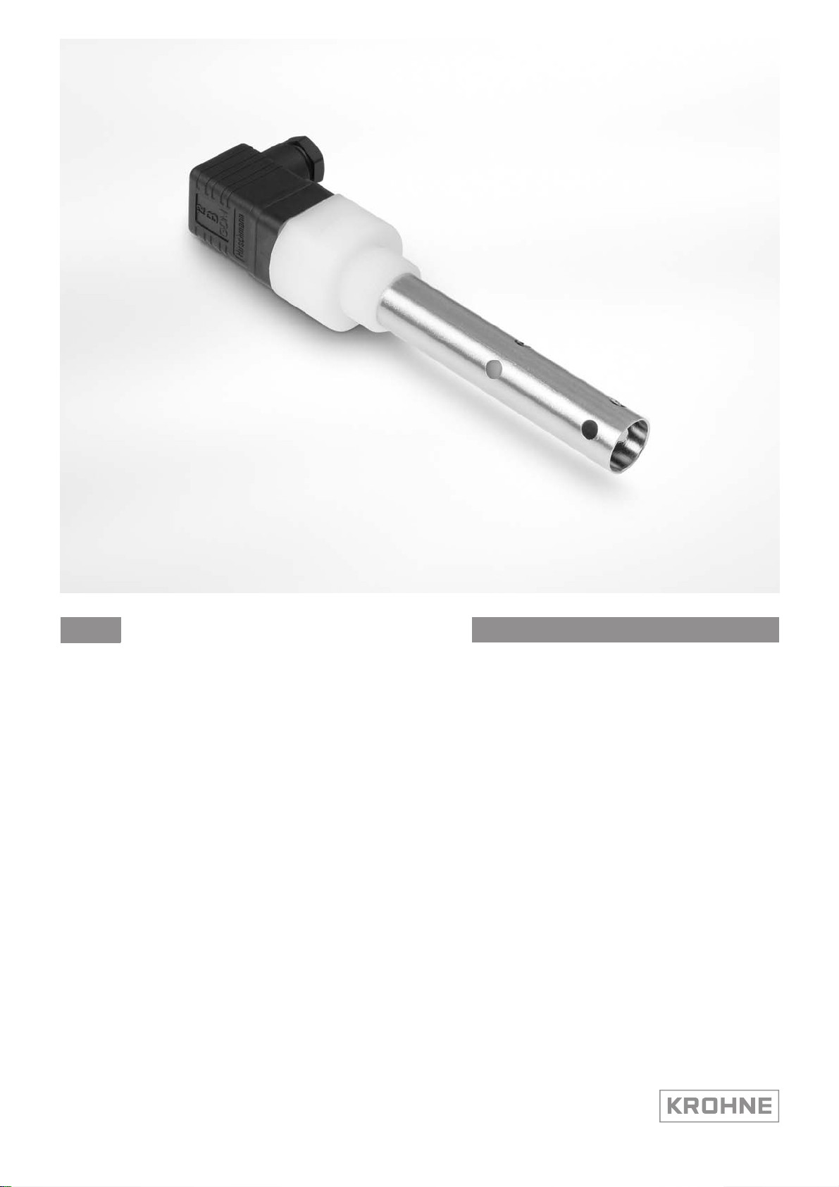
Conductive conductivity sensor
The documentation is only complete when used in combination with the relevant
documentation for the signal converter.
© KROHNE 01/2014 - 4001967301 - MA OPTISENS COND 1200 R01 en
Page 2

: IMPRINT :::::::::::::::::::::::::::::::::::::::
OPTISENS COND 1200
All rights reserved. It is prohibited to reproduce this documentation, or any part thereof, without
the prior written authorisation of KROHNE Messtechnik GmbH.
Subject to change without notice.
Copyright 2014 by
KROHNE Messtechnik GmbH - Ludwig-Krohne-Str. 5 - 47058 Duisburg (Germany)
2
www.krohne.com 01/2014 - 4001967301 - MA OPTISENS COND 1200 R01 en
Page 3

OPTISENS COND 1200
CONTENTS
1 Safety instructions 5
1.1 Intended use ..................................................................................................................... 5
1.2 Safety instructions from the manufacturer ..................................................................... 5
1.2.1 Copyright and data protection ................................................................................................ 5
1.2.2 Disclaimer ............................................................................................................................... 6
1.2.3 Product liability and warranty ................................................................................................ 6
1.2.4 Information concerning the documentation........................................................................... 6
1.2.5 Warnings and symbols used................................................................................................... 7
1.3 Safety instructions for the operator................................................................................. 7
2 Device description 8
2.1 Scope of delivery............................................................................................................... 8
2.2 Device description ............................................................................................................ 9
2.2.1 Conductivity sensor................................................................................................................. 9
2.3 Nameplate ...................................................................................................................... 10
3 Installation 11
3.1 General notes on installation ......................................................................................... 11
3.2 Storage and Transport ................................................................................................... 11
3.3 Installation procedure .................................................................................................... 11
3.4 Pre-installation requirements ....................................................................................... 12
3.5 Electrical connection......................................................................................................12
3.5.1 Connecting the cable to the sensor...................................................................................... 13
3.5.2 Cable assign of a Hirschmann plug...................................................................................... 14
3.5.3 Connecting the sensor cable to the signal converter .......................................................... 14
3.6 Calibrating the sensor.................................................................................................... 16
3.7 Installing the sensor....................................................................................................... 16
3.7.1 General installation instructions.......................................................................................... 16
3.7.2 Mounting to a flow through assembly .................................................................................. 20
3.7.3 Mounting sensor into immersion assembly......................................................................... 21
3.8 Examples of a typical measuring point.......................................................................... 22
4 Operation 23
4.1 Menu mode structure..................................................................................................... 23
4.2 Function tables ............................................................................................................... 24
4.2.1 Menu A, quick setup.............................................................................................................. 24
4.2.2 Menu B, test .......................................................................................................................... 24
4.2.3 Menu C, setup ....................................................................................................................... 25
4.3 Calibration ...................................................................................................................... 27
4.3.1 Temperature compensation .................................................................................................27
4.3.2 Calibrating measurement..................................................................................................... 30
4.3.3 Calibration log....................................................................................................................... 34
www.krohne.com01/2014 - 4001967301 - MA OPTISENS COND 1200 R01 en
3
Page 4

CONTENTS
OPTISENS COND 1200
5 Service 35
5.1 Maintenance ................................................................................................................... 35
5.1.1 Cleaning ................................................................................................................................ 35
5.1.2 Aging and re-calibration ....................................................................................................... 35
5.2 Spare parts availability...................................................................................................35
5.3 Availability of services .................................................................................................... 35
5.4 Returning the device to the manufacturer..................................................................... 35
5.5 Disposal .......................................................................................................................... 35
6 Technical data 36
6.1 Measuring principle........................................................................................................36
6.1.1 Conductive measurement..................................................................................................... 36
6.2 Technical data................................................................................................................. 37
6.3 Dimensions ..................................................................................................................... 39
7 Notes 42
4
www.krohne.com 01/2014 - 4001967301 - MA OPTISENS COND 1200 R01 en
Page 5

OPTISENS COND 1200
1.1 Intended use
CAUTION!
Responsibility for the use of the measuring devices with regard to suitability, intended use and
corrosion resistance of the used materials against the measured fluid lies solely with the
operator.
INFORMATION!
The manufacturer is not liable for any damage resulting from improper use or use for other than
the intended purpose.
The intended use of OPTISENS COND 1200 conductivity sensor is the measurement of conductive
liquids. The sensor is suitable for connection to the MAC 100 signal converter.
1.2 Safety instructions from the manufacturer
1.2.1 Copyright and data protection
The contents of this document have been created with great care. Nevertheless, we provide no
guarantee that the contents are correct, complete or up-to-date.
SAFETY INSTRUCTIONS 1
The contents and works in this document are subject to copyright. Contributions from third
parties are identified as such. Reproduction, processing, dissemination and any type of use
beyond what is permitted under copyright requires written authorisation from the respective
author and/or the manufacturer.
The manufacturer tries always to observe the copyrights of others, and to draw on works created
in-house or works in the public domain.
The collection of personal data (such as names, street addresses or e-mail addresses) in the
manufacturer's documents is always on a voluntary basis whenever possible. Whenever
feasible, it is always possible to make use of the offerings and services without providing any
personal data.
We draw your attention to the fact that data transmission over the Internet (e.g. when
communicating by e-mail) may involve gaps in security. It is not possible to protect such data
completely against access by third parties.
We hereby expressly prohibit the use of the contact data published as part of our duty to publish
an imprint for the purpose of sending us any advertising or informational materials that we have
not expressly requested.
www.krohne.com01/2014 - 4001967301 - MA OPTISENS COND 1200 R01 en
5
Page 6

1 SAFETY INSTRUCTIONS
1.2.2 Disclaimer
The manufacturer will not be liable for any damage of any kind by using its product, including,
but not limited to direct, indirect or incidental and consequential damages.
This disclaimer does not apply in case the manufacturer has acted on purpose or with gross
negligence. In the event any applicable law does not allow such limitations on implied warranties
or the exclusion of limitation of certain damages, you may, if such law applies to you, not be
subject to some or all of the above disclaimer, exclusions or limitations.
Any product purchased from the manufacturer is warranted in accordance with the relevant
product documentation and our Terms and Conditions of Sale.
The manufacturer reserves the right to alter the content of its documents, including this
disclaimer in any way, at any time, for any reason, without prior notification, and will not be liable
in any way for possible consequences of such changes.
1.2.3 Product liability and warranty
The operator shall bear responsibility for the suitability of the device for the specific purpose.
The manufacturer accepts no liability for the consequences of misuse by the operator. Improper
installation and operation of the devices (systems) will cause the warranty to be void. The
respective "Standard Terms and Conditions" which form the basis for the sales contract shall
also apply.
OPTISENS COND 1200
1.2.4 Information concerning the documentation
To prevent any injury to the user or damage to the device it is essential that you read the
information in this document and observe applicable national standards, safety requirements
and accident prevention regulations.
If this document is not in your native language and if you have any problems understanding the
text, we advise you to contact your local office for assistance. The manufacturer can not accept
responsibility for any damage or injury caused by misunderstanding of the information in this
document.
This document is provided to help you establish operating conditions, which will permit safe and
efficient use of this device. Special considerations and precautions are also described in the
document, which appear in the form of underneath icons.
6
www.krohne.com 01/2014 - 4001967301 - MA OPTISENS COND 1200 R01 en
Page 7
OPTISENS COND 1200
1.2.5 Warnings and symbols used
Safety warnings are indicated by the following symbols.
DANGER!
This information refers to the immediate danger when working with electricity.
DANGER!
This warning refers to the immediate danger of burns caused by heat or hot surfaces.
DANGER!
This warning refers to the immediate danger when using this device in a hazardous atmosphere.
DANGER!
These warnings must be observed without fail. Even partial disregard of this warning can lead to
serious health problems and even death. There is also the risk of seriously damaging the device
or parts of the operator's plant.
SAFETY INSTRUCTIONS 1
WARNING!
Disregarding this safety warning, even if only in part, poses the risk of serious health problems.
There is also the risk of damaging the device or parts of the operator's plant.
CAUTION!
Disregarding these instructions can result in damage to the device or to parts of the operator's
plant.
INFORMATION!
These instructions contain important information for the handling of the device.
LEGAL NOTICE!
This note contains information on statutory directives and standards.
• HANDLING
HANDLING
HANDLINGHANDLING
This symbol designates all instructions for actions to be carried out by the operator in the
specified sequence.
i RESULT
RESULT
RESULTRESULT
This symbol refers to all important consequences of the previous actions.
1.3 Safety instructions for the operator
WARNING!
In general, devices from the manufacturer may only be installed, commissioned, operated and
maintained by properly trained and authorized personnel.
This document is provided to help you establish operating conditions, which will permit safe and
efficient use of this device.
www.krohne.com01/2014 - 4001967301 - MA OPTISENS COND 1200 R01 en
7
Page 8
2 DEVICE DESCRIPTION
2.1 Scope of delivery
INFORMATION!
Inspect the cartons carefully for damages or signs of rough handling. Report damage to the
carrier and to the local office of the manufacturer.
INFORMATION!
Do a check of the packing list to make sure that you have all the elements given in the order.
INFORMATION!
Look at the device nameplate to ensure that the device is delivered according to your order.
Check for the correct supply voltage printed on the nameplate.
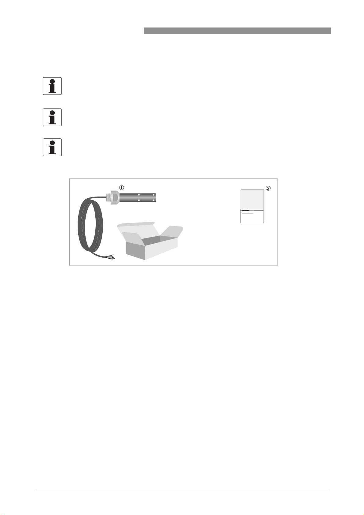
OPTISENS COND 1200
1 Ordered sensor
2 Documentation
Optional accessories
• SENSOFIT FLOW 1000 Flow-through assembly
• SENSOFIT IMM 1000 Immersion assembly
• SENSOFIT INS 1000 Screw-in adapter
Consumables/Spare parts available
• OPTISENS 1200 (W)
• OPTISENS 1200 (PW)
• OPTISENS 1200 (GF)
• Standard solution for sensor calibration
8
www.krohne.com 01/2014 - 4001967301 - MA OPTISENS COND 1200 R01 en
Page 9

OPTISENS COND 1200
2.2 Device description
2.2.1 Conductivity sensor
DEVICE DESCRIPTION 2
1 4-pin-right-angle plug
2 Process connection thread
3 Outside electrode
4 Inside electrode
The OPTISENS COND 1200 sensor is a conductive cellular measurement medium with an
integrated temperature sensor (Pt1000). It contains two stainless steel electrodes with PVDF
insulation that prevent proneness to soiling. It is available in various cell constants (c = 0.01,
0.05, 0.1, 0.2, 1.0) and thus covers a wide area of use. The conductivity sensor have a
standardised robust design and a long lifespan. In combination with a signal converter, it is
possible to create extremely reliable low-cost measurement systems, which is suitable for a
wide range of water analysis measurement tasks.
The conductive measurement principle is characterised by high sensitivity, especially at low
conductivity values. For this reason, the sensor is perfect for low-contamined, non-corrosive
media such as pure water, steam and cooling water as well as service water.
If the values exceed 20 mS/cm and in case of heavy soiling or danger of corrosion by the medium,
it is highly recommended to make use of the inductive measurement with the IND 1000 (see
handbook IND 1000).
www.krohne.com01/2014 - 4001967301 - MA OPTISENS COND 1200 R01 en
9
Page 10
2 DEVICE DESCRIPTION
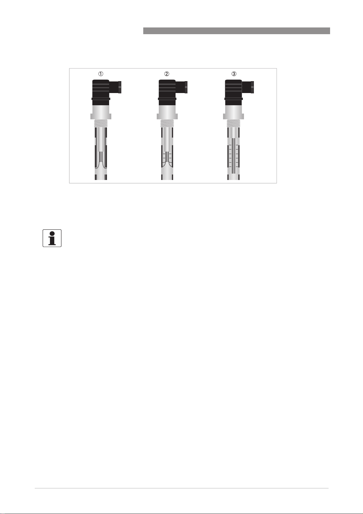
Sensor types
1 External sensor with high conductivity
2 External sensor with medium conductivity
3 External sensor with low conductivity
OPTISENS COND 1200
2.3 Nameplate
INFORMATION!
Look at the device nameplate to ensure that the device is delivered according to your order.
Check for the correct supply voltage printed on the nameplate.
The sensor type is specified on the labelling of the sensor package and on the sensor itself.
10
www.krohne.com 01/2014 - 4001967301 - MA OPTISENS COND 1200 R01 en
Page 11

OPTISENS COND 1200
3.1 General notes on installation
INFORMATION!
Inspect the cartons carefully for damages or signs of rough handling. Report damage to the
carrier and to the local office of the manufacturer.
INFORMATION!
Do a check of the packing list to make sure that you have all the elements given in the order.
INFORMATION!
Look at the device nameplate to ensure that the device is delivered according to your order.
Check for the correct supply voltage printed on the nameplate.
3.2 Storage and Transport
• Store the sensor in its original packaging in a dry and dust-free location. Keep it away from
dirt.
• The original packaging serves the protection of the equipment. Therefore always use it for
transport or return to the manufacturer.
• Avoid solar radiation.
INSTALLATION 3
3.3 Installation procedure
As a new inductivity sensor needs to be calibrated before it is installed into its final measuring
location, it is important to follow the installation order:
1. Unpack the sensor.
2. Connect the sensor to the signal converter.
3. Calibrate the sensor.
4. Install the sensor into its final measuring location.
The required steps are explained in the following sections.
www.krohne.com01/2014 - 4001967301 - MA OPTISENS COND 1200 R01 en
11
Page 12
3 INSTALLATION
3.4 Pre-installation requirements
CAUTION!
Never touch or scratch the sensor shaft or the inner electrode.
INFORMATION!
•
Install the sensor against the flow to ensure direct exposure of the electrodes.
•
Install the sensor only in T-pieces or flow through assembly of the manufacturer.
•
Avoid air getting trapped around the sensor.
•
Avoid solids collection around the electrodes.
3.5 Electrical connection
DANGER!
For devices used in hazardous areas, additional safety notes apply; please refer to the Ex
documentation.
DANGER!
All work on the electrical connections may only be carried out with the power disconnected.
OPTISENS COND 1200
DANGER!
Observe the national regulations for electrical installations!
WARNING!
Observe without fail the local occupational health and safety regulations. Any work done on the
electrical components of the measuring device may only be carried out by properly trained
specialists.
INFORMATION!
Look at the device nameplate to ensure that the device is delivered according to your order.
12
www.krohne.com 01/2014 - 4001967301 - MA OPTISENS COND 1200 R01 en
Page 13
OPTISENS COND 1200
3.5.1 Connecting the cable to the sensor
CAUTION!
Moisture inside the sensor connector must be avoided! Moisture may cause a shortcut and
deliver erratic readings!
If moisture has entered the connector, dry it with air (e.g. hair blower).
INSTALLATION 3
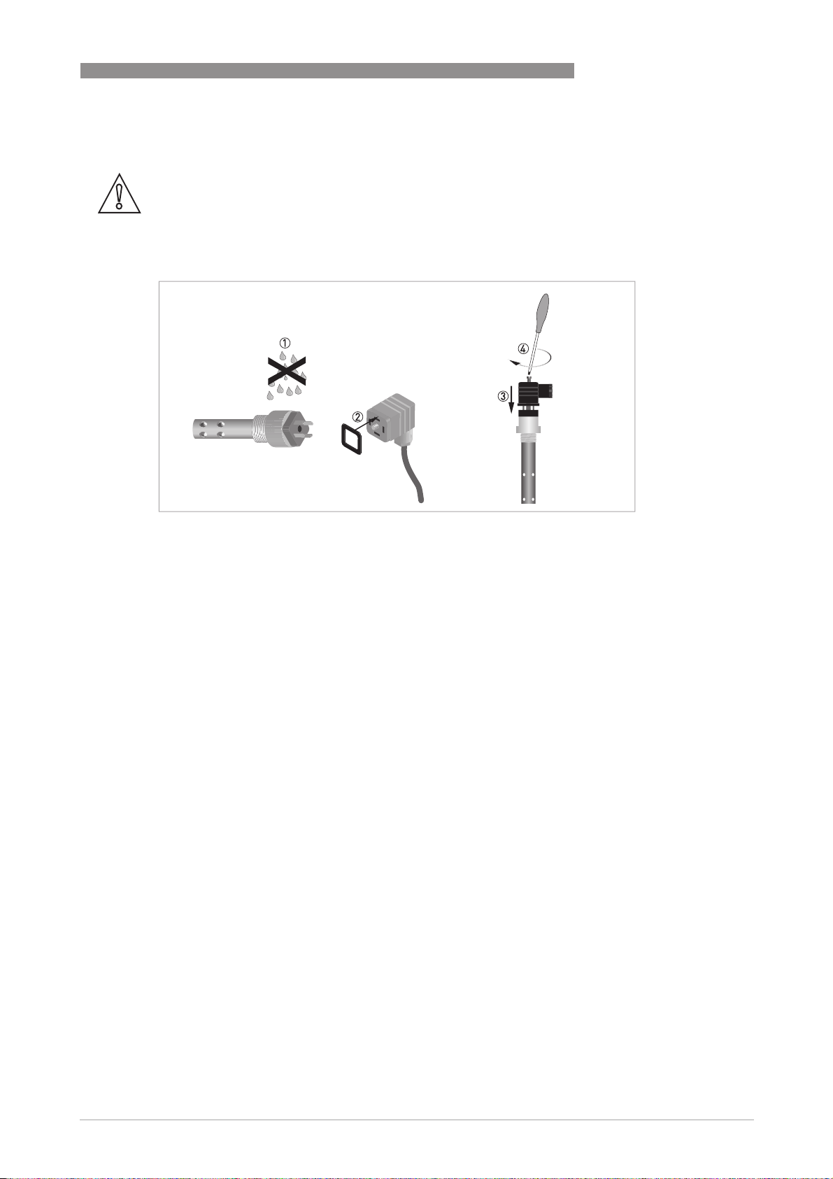
Figure 3-1: Connecting the Hirschmann plug to the sensor
Ensure that both cable and sensor connector are absolutely dry 1.
Make sure that the seal is positioned on the sensor connector 2.
Push the cable connector 3 on the sensor.
Screw the cable connector to the sensor and tighten it with a screw driver 4.
www.krohne.com01/2014 - 4001967301 - MA OPTISENS COND 1200 R01 en
13
Page 14

3 INSTALLATION
3.5.2 Cable assign of a Hirschmann plug
CAUTION!
Do not shorten the cable length. This can influence the measuring accuracy.
INFORMATION!
The given colours only refer to the delivered cables! When using cables of a different provider,
take into account the manufacturer
OPTISENS COND 1200
’
s notes concerning the cable colour and designation.
Figure 3-2: Cable assign of a Hirschmann plug
1 Cable LIYCY 4x0.5 mm
2 White
3 Brown
4 Yellow
5 Green
6 Shield
7 Pt100 sensor
8 Outer electrode
9 Inner electrode
3.5.3 Connecting the sensor cable to the signal converter
DANGER!
All work on the electrical connections may only be carried out with the power disconnected. Take
note of the voltage data on the nameplate!
CAUTION!
’
t connect the shielding to the signal converter if the sensor has got a Hirschmann GDM 3011
Don
plug!
INFORMATION!
Look at the device nameplate to ensure that the device is delivered according to your order.
Check for the correct supply voltage printed on the nameplate.
14
www.krohne.com 01/2014 - 4001967301 - MA OPTISENS COND 1200 R01 en
Page 15

OPTISENS COND 1200
1 Sensor connection terminals
2 Terminal block S (protective earth)
3 Terminal block A: terminals for sensor
4 Terminal block B: terminals for sensor
When ordering the single channel version, only the interface "Pos.A" is populated. In the version
with dual channels the interfaces "Pos.A" and "Pos.B" are populated.
INSTALLATION 3
Connecting the sensor cable to the signal converter
• Thread the sensor cable through the middle right cable gland 1.
• Push the wire 7 into the terminal block Pos. A or Pos. B as described in the chart.
• To remove a cable, press down the white clip 8 on the corresponding terminal and pull the
cable out.
Wire Terminal block Pos. A / B
Green 2 X
Yellow 3 P
White 4 I
Brown 5 E
www.krohne.com01/2014 - 4001967301 - MA OPTISENS COND 1200 R01 en
15
Page 16

3 INSTALLATION
3.6 Calibrating the sensor
Before the sensor is installed, it has to be calibrated. Proceed as described on page 27. Then
continue with the installation procedure.
3.7 Installing the sensor
3.7.1 General installation instructions
WARNING!
Ensure that the pipe is without pressure before installing or removing a sensor!
INFORMATION!
This installation procedure is only recommended for very clean water without any particles in
the water. Otherwise turn the flow-through assembly and be sure that the tube is completely
filled with water, otherwise the measuring reading is wrong.
INFORMATION!
During installation you should fix a shut-off valve in front of and behind the instrument so that
the sensor can be taken out of the bypass in case of check.
OPTISENS COND 1200
INFORMATION!
To achieve reliable measuring results, note the following items:
•
Always install the sensor in the designated flow through assembly.
•
The sensor must always have full contact with the measuring medium.
Figure 3-3: Installation requirements for the sensor
1 Flow
= 30 l/h / 7.93 gal/h
min
16
www.krohne.com 01/2014 - 4001967301 - MA OPTISENS COND 1200 R01 en
Page 17

OPTISENS COND 1200
Installation recommendation
Installation recommendation
Installation recommendationInstallation recommendation
Figure 3-4: Typical installation
1 Flow direction
2 Ordered sensor
• Installation against the flow to ensure direct exposure of the electrodes.
INSTALLATION 3
Figure 3-5: Installation for clean water
1 Flow direction
2 Ordered sensor
• This installation is only recommended if there are no particles or air bubbles in the pipe.
www.krohne.com01/2014 - 4001967301 - MA OPTISENS COND 1200 R01 en
17
Page 18

3 INSTALLATION
Figure 3-6: Installation for clean water
1 Flow direction
2 Ordered sensor
• This installation is only recommended if the pipe is completely filled.
OPTISENS COND 1200
18
Figure 3-7: Possible installation
1 Flow direction
2 Ordered sensor
• This installation is only recommended if the pipe is completely filled.
• Consider the diameter of the pipe, i.e. compare pipe DN with insertion length of the sensor
shaft.
www.krohne.com 01/2014 - 4001967301 - MA OPTISENS COND 1200 R01 en
Page 19

OPTISENS COND 1200
Figure 3-8: Possible installation
1 Flow direction
2 Ordered sensor
• This installation is only recommended if the pipe is completely filled and if there are no
particles or air bubbles in the pipe.
INSTALLATION 3
www.krohne.com01/2014 - 4001967301 - MA OPTISENS COND 1200 R01 en
19
Page 20

3 INSTALLATION
3.7.2 Mounting to a flow through assembly
WARNING!
Ensure that the pipe is without pressure before installing or removing a sensor!
INFORMATION!
The flow through assembly is an optional accessory and not part of the standard scope of
delivery. It has to be installed horizontally in pump or sample lines or directly in the process.
OPTISENS COND 1200
Figure 3-9: Possible mounting positions of the flow-through assembly
1 Mounting in an outlet pipe
2 Mounting in a bypass pipe
3 Shut-off valve
4 Sensor installed in flow through assembly
Figure 3-10: Installing the sensor into the flow-through assembly
1 Process connection
2 Protective cage
3 Flow direction
4 Female thread
5 4-pin-right-angle plug
6 Sensor
20
• Make sure that the plug 5 is connected to the sensor 6.
• Screw the sensor into the female thread 4 of the flow through assembly. Tighten the sensor
by hand.
www.krohne.com 01/2014 - 4001967301 - MA OPTISENS COND 1200 R01 en
Page 21

OPTISENS COND 1200
3.7.3 Mounting sensor into immersion assembly
1 Immersion assembly
2 Sensor-assembly connector
3 Clamps
4 Caps with cable gland
5 Sensor (only for immersion version with attached cable)
INSTALLATION 3
1 Sensor with attached cable
2 Sensor-assembly connector
3 Immersion assembly
4 Clamps onto immersion assembly
5 Cap with cable gland
• Pull the cap with cable gland 5 off the immersion assembly
• Push the sensor cable through the sensor-assembly connector 2, the immersion assembly
3 and the cap with cable gland 5.
• Screw the sensor-assembly connector 2 into the immersion assembly 3. Then screw the
sensor 1 into the sensor-assembly connector.
• Push the cap with cable gland onto the immersion assembly again 4.
www.krohne.com01/2014 - 4001967301 - MA OPTISENS COND 1200 R01 en
21
Page 22

3 INSTALLATION
3.8 Examples of a typical measuring point
The following examples each show the signal converter, a sensor with integrated temperature
sensor, and the flow-through or immersion assembly.
OPTISENS COND 1200
1 Bypass measurement
2 Inlet measurement
3 Shut-off valve
4 Flow-through assembly with sensor
5 Bypass pipe
6 Main pipe
22
Figure 3-11: Installation with signal converter
1 Single channel version
2 Dual channel version
www.krohne.com 01/2014 - 4001967301 - MA OPTISENS COND 1200 R01 en
Page 23

OPTISENS COND 1200
4.1 Menu mode structure
INFORMATION!
The following table just presents an overview. When programming the device, always consult the
function tables additionally as they contain further information!
Only the sensor relevant menus are shown in the following tables. For detailed information
about the general setting refer to the signal converter manual.
Main menu Submenu Parameter
A quick setup
A quick setup A6 analog outputs A6.1 measurement For further information
A quick setupA quick setup
B test
B test B1 sim. process input A B1.1 temperature For further information
B testB test
C setup
C setup C1 process input A C1.1 parameter For further information
C setupC setup
A6.2 spec. conductivity
B1.2 spec. conductivity
B1.3 spec. resistance
B4 actual values B4.2 process input A
B4.2.1 temperature
B4.2.2 spec. conductivity
B4.2.3 Meg. Ohm
B4.2.5 pH
B4.2.8 generator volt.
B4.2.9 CPU temp.
B4.2.10 range
B4.2.11 electrode volt.
B6 information B6.2 process input A
C1.2 cell constant
C1.3 cable resistance
C1.4 concentration
C1.14 time constant
C1.15 temperature
C1.23 cell calibration
OPERATION 4
see function tables.
see function tables.
see function tables.
www.krohne.com01/2014 - 4001967301 - MA OPTISENS COND 1200 R01 en
23
Page 24

4 OPERATION
4.2 Function tables
4.2.1 Menu A, quick setup
INFORMATION!
Note that the appearance of some sub-menus depends on the hardware setting and the used
sensor(s). Also only the sensor relevant menus and submenus are shown here in detail. For all
other menu functions refer to the MAC 100 signal converter manual.
A 6.1 measurement:
A 6.1 measurement:
A 6.1 measurement: A 6.1 measurement:
Value used for driving the current output C. Choose between:
• spec. conductivity
• temperature
• spec. resistance
• spec. conductivity
A 6.2 spec. conductivity
A 6.2 spec. conductivity
A 6.2 spec. conductivityA 6.2 spec. conductivity
OPTISENS COND 1200
Unit for the current output range. Choose between:
• µS/cm
• mS/cm
• free unit
4.2.2 Menu B, test
INFORMATION!
Note that the appearance of some sub-menus depends on the hardware setting and the used
sensor(s). Also only the sensor relevant menus and sub-menus are shown here in detail. For all
other menu functions refer to the MAC 100 signal converter manual.
The procedure to start the simulation process is the same for all functions:
• Choose the function with the help of ↓ or ↑ and press ^.
i You see the two options "set value" (opens the editor to enter the simulation value) and
"break" (exits the menu without simulation).
• Choose the desired option with the help of ↑ or ↓ and press ^.
i If you chose "set value", the device asks "start simulation" and offers the options "no" (exits
the menu without simulation) or "yes" (starts the simulation finally).
• Choose the desired option with the help of ↑ or ↓ and press ^.
i If you chose "yes", the simulation starts.
24
www.krohne.com 01/2014 - 4001967301 - MA OPTISENS COND 1200 R01 en
Page 25

OPTISENS COND 1200
OPERATION 4
B1,sim.process inp.A
B2,sim.process inp.B
Level Designation / function Settings / descriptions
B1.1
B1.1 temperature In this menu the temperature can be simulated.
B1.1B1.1
B1.2
B1.2 spec. conductivitiy In this menu the conductivity can be simulated.
B1.2B1.2
B1.3
B1.3 spec. resistance In this menu the resistance can be simulated.
B1.3B1.3
B4, actual values
Level Designation / function Settings / descriptions
This menu groups several functions which allow to display the corresponding actual reading. The shown measurements
are depending on the device configuration.
B4.2
B4.2 process input A In this menu the measurements from process input A can be read.
B4.2B4.2
B4.3
B4.3 process input B In this menu the measurements from process input B can be read. (for 2
B4.3B4.3
channel version only)
B6, information
Level Designation / function Settings / descriptions
This menu groups several other menus which contain device specific information. The build-up of the display is the
same for all menus:
st
• 1
line: ID No. of the circuit board
nd
• 2
line: software version
rd
• 3
line: production date
B6.2
B6.2 process input A Gives information about the electronical part of process input A.
B6.2B6.2
B6.3
B6.3 process input B In this menu the measurements from process input B can be read. (for 2
B6.3B6.3
channel version only)
4.2.3 Menu C, setup
INFORMATION!
The signal converter has a dual process input, A and B. Each process input has an own submenu
in this main menu. Process input A is always present, i.e. there is always a board in the interface
"Pos.A" in the connection area. The interface of process input B only has a board with the dual
channel signal converter. Be aware that the definition which kind of measurement a process
input can do is defined when ordering the device. The configuration cannot be changed later.
INFORMATION!
Note that the appearance of some submenus depends on the hardware setting and the used
sensor(s).
www.krohne.com01/2014 - 4001967301 - MA OPTISENS COND 1200 R01 en
25
Page 26

4 OPERATION
C1, process input A
C1, process input A
C1, process input AC1, process input A
C2, process input B
C2, process input B
C2, process input BC2, process input B
OPTISENS COND 1200
Level Designation / function Settings / descriptions
Process input A and B can be either a sensor 1 or a sensor 2. Further information about the type of sensor 1 or 2 please
refer to MAC 100 manual "Sensor input combinations". Process input A is always present, process Input B can be
present.
Note: The exchange of a sensor 1 with a sensor 2, or vice versa, can only be done by the manufacturer!
Depending on the sensor which is connected to a slot A or B the menu changes.
C1.1
C1.1 parameter (conductivity) This menu item is for selecting the probe which is connected to process
C1.1C1.1
C1.2
C1.2 cell constant Enter cell constant.
C1.2C1.2
C1.3
C1.3 cable resistance Enter cable resistance in Ohm
C1.3C1.3
C1.14
C1.14 time constant Enter time constant.
C1.14C1.14
C1.15
C1.15 temperature Menu for temperature measurement. Available for sensor 1 and sensor 2.
C1.15C1.15
C1.15.1 probe Options:
input A/B. The entries of this selection depends on the chosen device
configuration. The device configuration is customer specific and set during
production.
• manual: used if no internal or external temperature sensor is connected to
the signal converter
• Pt1000: used if an external Pt1000 temperature sensor is connected to the
signal converter
C1.15.2 manual Only available if C1.15.1 is set to "manual". If you have chosen "manual"
C1.15.3 correction Offset correction for temperature measurement. Not available if C1.15.1 is
C1.15.4 limitation Measuring ranges for temperature measurement. Enter limitation
C1.15.5 temp. comp. Menu for editing the temperature compensation parameters for the
enter temperature.
set to "manual". If you have chosen “Pt 1000” enter the temperature
correction.
measurement.
Options:
• off
• table
• ultra pure water NACl
• ultra pure water Nao3
• upw morpholin
• ultra pure water NH3
• ultra pure water HCL
• ultra pure water
• linear
C1.15.6 temp. coefficient If you have chosen “linear” enter the temperature coefficient.
C1.15.7 ref. temperature If you have chosen “linear” enter the reference temperature.
C1.15.8 Reference points Only available if C1.15.5 is set to “table”. Choose:
• 2 till 10
C1.15.9 tbl. temperature Only available if C1.15.5 is set to “table”. Choose:
• temperature for each row
C1.15.10 tbl. conductivity Only available if C1.15.5 is set to “table”. Choose:
• conductivity for each row
C1.23
C1.23 cell calibration For detailed information refer to calibration on page 30
C1.23C1.23
C1.23.1 temp. comp. Menu for temperature measurement.
Options:
• off: temperature measurement is disabled.
• manual: temperature value has to be entered manually.
• automatic: temperature measurement is performed as configured
26
www.krohne.com 01/2014 - 4001967301 - MA OPTISENS COND 1200 R01 en
Page 27

OPTISENS COND 1200
Level Designation / function Settings / descriptions
OPERATION 4
C1.23.2 temperature Menu for setup of manual temperature (manual temperature
C1.23.3 temp. coefficient Menu for setup of temperature coefficient (manual temperature
C1.23.4 spec. conductivity Enter the conductivity of the calibration fluid.
C1.23.5 cell constant Enter cell constant.
measurement).
measurement).
Menu for preparation of measurement:
• Put probe into calibration fluid
• Wait until measurement is stable.
• Press enter to proceed.
Wait until concentration is measured.
Check slope, press enter, decide whether to store or to discard calibration
parameter.
CAUTION!
If you choose for measurement the temperature compensation "linear" than choose between
"automatic" or "manual" for the temperature compensation during calibration. If you choose for
measurement the temperature compensation "off" than choose also "off" for the temperature
compensation during calibration.
4.3 Calibration
4.3.1 Temperature compensation
There are three basic options for temperature compensation:
• automatic:
automatic: the signal converter will automatically compensate temperature influences using
automatic:automatic:
the information of a Pt1000 temperature sensor.
• manual:
manual: the signal converter will compensate temperature influences using a manually
manual:manual:
entered value; this option only makes sense if the temperature of the measured medium is
quite constant.
• off:
off: temperature compensation is disabled.
off:off:
INFORMATION!
If you choose no compensation, the measured conductivity will most probably deviate
considerably from the actual conductivity. The reason is that the conductivity of a specific
medium varies depending on the temperature of the medium.
The menu for the type of temperature compensation offers the following options:
• Pt1000
Pt1000: choose this option if there is an external Pt1000 temperature sensor connected to the
Pt1000Pt1000
signal converter.
• manual
manual: choose this option if there is no internal or external temperature sensor connected
manualmanual
to the signal converter.
After starting-up the signal converter, the measuring screen appears. This is the standard
screen which is displayed automatically in the normal operating mode. If you are in this mode
and you want to adjust the temperature compensation, you have to perform the following steps:
www.krohne.com01/2014 - 4001967301 - MA OPTISENS COND 1200 R01 en
27
Page 28

4 OPERATION
Step 1: activating the temperature compensation for measurement
OPTISENS COND 1200
• Press >
• Press
• Now you can set up the temperature compensation. Press or to select off
> for more than 2.5 seconds, then release the button. You are on the main menu level. In the
>>
upper line of the display "A" appears, beneath the main menu quick setup
or until the main menu setup
MAIN MENU
A quick setup
B test
> C setup
> C setup
> C setup> C setup
D service
• Press >
> to enter the chosen menu.
>>
You are on the first submenu level. In the upper line of the display "setup" and "c1" appears,
beneath the submenu process input A
• Press
• Press >
or to select process input A
> to enter the chosen menu.
>>
You are on the second submenu level. In the upper line of the display "process input A"
and "c1.1"appears beneath the submenu parameter
• Press
• Press >
• Press
• Press >
or to select temperature
> to enter the chosen menu.
>>
You are on the third submenu level. In the upper line of the display "temperature"
and "C1.15.1" appears, beneath the submenu probe
or to select temp. comp.
> to enter the chosen menu.
>>
setup is highlighted.
setupsetup
process input A is highlighted.
process input Aprocess input A
process input A.
process input Aprocess input A
temperature
temperaturetemperature
temp. comp.
temp. comp.temp. comp.
quick setup is highlighted.
quick setupquick setup
parameter is highlighted.
parameterparameter
probe is highlighted
probeprobe
off or linear
offoff
^ to confirm the entered value.
linear. Press
linearlinear
28
www.krohne.com 01/2014 - 4001967301 - MA OPTISENS COND 1200 R01 en
Page 29

OPTISENS COND 1200
Step 2: choosing the type of temperature compensation
OPERATION 4
Step 2a: probe Pt100/1000
Read the currently measured temperature of the Pt1000 temperature sensor from the measurement
screen and write it down.
Measure the temperature with a reference thermometer and check if it deviates from the temperature
measured by the Pt1000.
• Press >
• Press
probe Pt100/1000
probe Pt100/1000probe Pt100/1000
> for more than 2.5 seconds, then release the button. You are on the main menu level. In the
>>
upper line of the display "A" appears, beneath the main menu setup
or until the main menu setup
MAIN MENU
A quick setup
B test
> C setup
> C setup
> C setup> C setup
D service
• Press >
> to enter the chosen menu.
>>
You are on the first submenu level. In the upper line of the display "setup" and "c1" appears,
beneath the submenu process input A
pH is configurated.
• Press
• Press >
or to select process input A
> to enter the chosen menu .
>>
You are on the second submenu level. Press or until the submenu temperature
highlighted.
• Press >
> to enter the chosen menu.
>>
You are on the third submenu level. Press or until the submenu correction
highlighted.
setup is highlighted.
setupsetup
process input A is highlighted. Choose process input A or B where ever
process input Aprocess input A
process input A.
process input Aprocess input A
setup is highlighted.
setupsetup
temperature is
temperaturetemperature
correction is
correctioncorrection
• Press ^ to enter the chosen menu
• If necessary, enter the temperature correction in Kelvin so that the signal converter shows the
same temperature as the reference thermometer. Press ^ to confirm the entered value. The
temperature sensor has been adjusted.
www.krohne.com01/2014 - 4001967301 - MA OPTISENS COND 1200 R01 en
29
Page 30

4 OPERATION
OPTISENS COND 1200
Step 2b: probe manual
Measure the temperature of the measuring medium.
• Press >
• Press
probe manual
probe manualprobe manual
> for more than 2.5 seconds, then release the button. You are on the main menu level. In the
>>
upper line of the display "A" appears, beneath the main menu setup
or until the main menu setup
MAIN MENU
A quick setup
B test
> C setup
> C setup
> C setup> C setup
D service
• Press >
> to enter the chosen menu.
>>
You are on the first submenu level. In the upper line of the display "setup" and "c1" appears,
beneath the submenu process input A
• Press
• Press >
or to select process input A
> to enter the chosen menu process input A
>>
You are on the second submenu level. Press or until the submenu temperature
highlighted.
• Press >
> to enter the chosen menu. The submenu probe
>>
• Press
setup is highlighted.
setupsetup
process input A is highlighted.
process input Aprocess input A
process input A.
process input Aprocess input A
process input A.
process input Aprocess input A
or until the submenu manual
setup is highlighted.
setupsetup
probe is highlighted.
probeprobe
manual is highlighted.
manualmanual
temperature is
temperaturetemperature
• Press ^ to enter the chosen menu
• Enter the measured temperature. Press ^ to confirm the entered value. The manually
measured temperature will now be used for temperature compensation.
4.3.2 Calibrating measurement
Calibration is necessary in regular intervals or when installing a new sensor.
When calibrating a conductivity measurement, keep in mind that the measuring system as a
whole is calibrated, and not only the sensor. Therefore the measuring system has to be
recalibrated if, for example, the measuring medium changes.
In an intact sensor, the optimal slope is 59 mV and the optimal zero point is 0 mV. The slope
should at least have a value between 50...65 mV.
Re-calibrate the sensor if the slope does not approximate those limits.
As the sensor ages, the slope gets flatter and the zero error increases. When one or both of
these values exceed certain limits, the signal converter displays a message indicating that the
sensor has to be exchanged.
To avoid alarms on the distrubted control system (DLC) when temporarily removing the sensor
(i.e. for maintenance), the signal converter has a hold function. This function "freezes" all
outputs (i.e. the display and the current outputs) of the last measured value.
INFORMATION!
As an indication that the hold function is active, the "warning sign" in the upper left corner of the
display appears. Meanwhile the status messages show "checks in progress". For more details
about how to select the manual hold function refer to the signal converter documentation.
30
www.krohne.com 01/2014 - 4001967301 - MA OPTISENS COND 1200 R01 en
Page 31

OPTISENS COND 1200
After starting-up the signal converter, the measuring screen appears. This is the standard
screen which is displayed automatically in the normal operating mode. If you are in this mode
and you want to initiate a calibration, you have to activate the manual hold function performing
the following steps.
Step 1: activating the hold function
OPERATION 4
• Press >
• Press
> for more than 2.5 seconds, then release the button. You are on the main menu level. In the
>>
upper line of the display "A" appears, beneath the main menu quick setup
or until the main menu quick setup
MAIN MENU
> A quick setup
> A quick setup
> A quick setup> A quick setup
B test
Csetup
D service
• Press >
> to enter the chosen menu.
>>
You are on the first submenu level. In the upper line of the display "quick setup" and
A1" appears, beneath the submenu language
• Press
• Press >
or until the submenu hold function
> to enter the chosen menu.
>>
quick setup is highlighted.
quick setupquick setup
You are on the second submenu level. In the upper line of the display
"manual hold" appears, beneath the option off
• Press
or to choose the option on
quick setup is highlighted.
quick setupquick setup
language is highlighted.
languagelanguage
hold function is highlighted.
hold functionhold function
off is highlighted
offoff
• Press ^ to confirm the entered value.
• You have activated the hold function. To go to the next step and prepare the calibration
procedure. You have to return to the measuring mode.
• Press ^ until you reach the measuring mode again
Step 2: preparing the calibration procedure
• If you calibrate a new sensor, make sure that the sensor is correctly connected to the signal
converter.
• Check the sensor for damages or dirt deposits.
• Provide a suitable standard solution. Further information on page 8
After activating the hold function and the preparative measures, you can get access to the
calibration procedure from the measuring mode via the main menu setup
www.krohne.com01/2014 - 4001967301 - MA OPTISENS COND 1200 R01 en
setup (step 3a).
setupsetup
31
Page 32

4 OPERATION
OPTISENS COND 1200
Step 3a: accessing the calibration menu via the main menu setup
• Press >
• Press
> for more than 2.5 seconds, then release the button. You are on the main menu level. In the
>>
upper line of the display "A" appears, beneath the main menu quick setup
or until the main menu setup
MAIN MENU
A quick setup
B test
> C setup
> C setup
> C setup> C setup
D service
• Press >
> to enter the chosen menu.
>>
You are on the first submenu level. In the upper line of the display "setup" and "c1"
appears, beneath the submenu process input A
• Press
• Press >
setup is highlighted.
setupsetup
process input A is highlighted.
process input Aprocess input A
or to select process input A
> to enter the chosen menu.
>>
You are on the second submenu level. In the upper line of the
display "process input A" and "C1.1" appears, beneath the
submenu parameter
• Press
• Press >
process input A is highlighted.
process input A process input A
parameter is highlighted.
parameterparameter
or until the submenu cell calibration
> to enter the chosen menu.
>>
quick setup is highlighted.
quick setupquick setup
setup
setupsetup
cell calibration is highlighted.
cell calibrationcell calibration
• You can start the calibration procedure now as described in "Step 4".
32
www.krohne.com 01/2014 - 4001967301 - MA OPTISENS COND 1200 R01 en
Page 33

OPTISENS COND 1200
Step 4: calibration procedure
• After choosing the submenu cell calibration
pressing >>>>.
i The signal converter demands to choose the kind of temperature compensation. You have
the options "off", "automatic" and "manual" ( refer to
27). Please select the same kind of temperature compensation for the calibration as for the
measurement.
• If you chose "automatic", just press ^^^^. If you chose "manual", first enter the temperature and
the temperature coefficient of the measured medium using or and then press ^^^^.
i On the screen the message spec.conductivity
• Enter the specific conductivity in µS/cm
• The signal converter now performs a measurement which takes 20 seconds.
i On the screen the message cell constant appears
• Enter the cell constant in 1/cm.
i The signal converter now asks store cal. value?
OPERATION 4
cell calibration (step 3a) in the previous steps, continue by
cell calibrationcell calibration
spec.conductivity appears.
spec.conductivityspec.conductivity
Temperature compensation
on page
• Choose yes
• Press ^^^^ to confirm.
yes to store the calibration values. Choose no
yesyes
no to discard the results.
nono
i Prior returning to the measuring display, you are asked if the configuration should be
stored.
• Choose yes
yes using or to store the new calibration values.
yesyes
i You have completed the calibration.
• If you want to return to the measuring mode, press ^^^^ several times until you reach this mode.
INFORMATION!
The "stored value" is a calculated value based on the actual measurement. The signal converter
calculates this value depending on the compensation methods (temperature compensation)
chosen for the calibration. Do not change the compensation method in the time between the
measurement of the "stored value" and the input of the reference value. Otherwise this could
result in a wrong calibration.
Step 5: re-installing the sensor
• After the calibration procedure, rinse the sensor with tap water.
• Reinstall the sensor into its assembly, refer to
Installing the sensor
on page 16.
Step 6: switching back to measurement
• Deactivate the function "hold function " again.
www.krohne.com01/2014 - 4001967301 - MA OPTISENS COND 1200 R01 en
33
Page 34

4 OPERATION
4.3.3 Calibration log
INFORMATION!
In order to show the history of the calibrations, the converter has a calibration logbook function.
Up to 64 entries of the calibration history are stored including date and time.
Accessing the calibtration log
OPTISENS COND 1200
• Press >
• Press
> for more than 2.5 seconds, then release the button. You are on the main menu level. In the
>>
upper line of the display "A" appears, beneath the main menu quick setup
or until the main menu test
MAIN MENU
A quick setup
> B test
> B test
> B test> B test
C setup
D service
Press >>>> to enter the chosen menu.
You are on the first submenu level. In the upper line of the display "test" and "B1" appears,
beneath the submenu sim.process input A
Press or until the submenu logbooks
Press >>>> to enter the chosen menu.
You are on the second submenu level. In the upper line of the display "logbooks" and
"B5.1" appears, beneath the submenu status log
Press or until the submenu calibration log
Press >>>> to enter the chosen menu.
test is highlighted.
testtest
sim.process input A is highlighted.
sim.process input Asim.process input A
logbooks is highlighted.
logbookslogbooks
status log is highlighted.
status logstatus log
calibration log is highlighted.
calibration logcalibration log
quick setup is highlighted.
quick setupquick setup
• You are on the data level and you see the calibration history. With the help of or you can
scroll through the different entries.
• If you want to return to the measuring mode press ^^^^ several times until you reach this mode.
34
www.krohne.com 01/2014 - 4001967301 - MA OPTISENS COND 1200 R01 en
Page 35

OPTISENS COND 1200
5.1 Maintenance
5.1.1 Cleaning
• Clean the sensor surface with pure water.
• Slight dirt residues or dust: Rinse the sensor with tap water and clean it with a soft tissue.
• Oily and greasy coatings: Remove with a warm soap solution and rinse with water.
• Hardness deposits or metal hydroxide deposits: Remove with 10% citric acid or hypochloric
acid and rinse with water.
5.1.2 Aging and re-calibration
When the sensor becomes too old to provide reliable measurements, the signal converter
displays an error message after the calibration procedure. In this case, the sensor has to be
exchanged.
5.2 Spare parts availability
The manufacturer adheres to the basic principle that functionally adequate spare parts for each
device or each important accessory part will be kept available for a period of 3 years after
delivery of the last production run for the device.
SERVICE 5
This regulation only applies to spare parts which are subject to wear and tear under normal
operating conditions.
5.3 Availability of services
The manufacturer offers a range of services to support the customer after expiration of the
warranty. These include repair, maintenance, technical support and training.
INFORMATION!
For more precise information, please contact your local sales office.
5.4 Returning the device to the manufacturer
5.5 Disposal
CAUTION!
Disposal must be carried out in accordance with legislation applicable in your country.
www.krohne.com01/2014 - 4001967301 - MA OPTISENS COND 1200 R01 en
35
Page 36

6 TECHNICAL DATA
6.1 Measuring principle
6.1.1 Conductive measurement
OPTISENS COND 1200
Figure 6-1: Measuring principle for conductivity measurement
1 Inner electrode
2 Outer electrode
3 Current measurement
4 Power supply
5 Measuring medium
The principle of conductivity measurement is defined as the capacity of a solution to conduct an
electrical current between two electrodes. For determining the electrolytic conductivity it is
necessary to record the number of dissolved ions summarily. The parameter serves as a scale
for water purity and is given in Siemens. As there are two open cells, mutual voltage is being
produced. This one on its part generates electricity depending on the resistance of the medium.
As the medium is in direct contact with the electrode, the medium reacts faster to differences in
measuring values. The integrated temperature sensor compensates the conductivity.
Using Ohm’s law: Ohm = Voltage/Current, the resistance of a liquid can be determined by
measuring the current while keeping voltage constant. Specific conductivity is defined by
1/resistance. The unit of measurement is Siemens and is normally expressed in μS/cm or
mS/cm. An important criterion for the measuring range of conductivity cells is the geometry of
the electrodes. There are two rules which are characteristic for conductivity measurement:
1. The larger the distance between the two electrodes, the larger the resistance.
2. The larger the electrode surface, the lower the resistance.
The surface area (A) and the distance (L) must be correctly matched to the desired measuring
range. This is called the "cell constant" defined as c=L/A.
36
www.krohne.com 01/2014 - 4001967301 - MA OPTISENS COND 1200 R01 en
Page 37

OPTISENS COND 1200
6.2 Technical data
Measuring system
Measuring system
Measuring systemMeasuring system
Measuring principle Conductive conductivity
Measuring range OPTISENS COND 1200 (W)
Materials
Construction OPTISENS COND 1200 (W):
Sensor options With integrated Pt100 temperature sensor
Process connection OPTISENS COND 1200 (W):
TECHNICAL DATA 6
0.1...200 µS/cm (c=0.05)
1...2000 µS/cm (c=0.2)
1...20 mS/cm (c=1)
OPTISENS COND 1200 (PW)
0.05...10 µS/cm (c=0.01)
0.001...1 mS/cm (c=0.1)
OPTISENS COND 1200 (GF)
10 µS/cm...15 mS/cm (c=1)
Body: PVDF
Cell: Stainless steel (1.4571)
OPTISENS COND 1200 (PW):
Body: PVDF
Cell: Stainless steel (1.4571) or titanium
OPTISENS COND 1200 (GF):
Body: PVDF
Cell: Graphite (GF)
G3/4 A male thread
G1/2 A male thread for immersion assembly
OPTISENS COND 1200 (PW/GF):
G3/4 A male thread
G1/2 A male thread
G1 A male thread
3/4-14 NPT male thread
Measuring accuracy
Conductivity accuracy OPTISENS COND 1200 (W): +/- 2% full scale 1
OPTISENS COND 1200 (PW): +/-10% from the nominal value 1
OPTISENS COND 1200 (GF): +/-10% from the nominal value 1
Operating conditions
Temperature range OPTISENS COND 1200 (W/PW):
Max. operating pressure OPTISENS COND 1200 (W/PW):
1 Depending on the production conditions, the cell constant can deviate from the nominal value. This deviation can be
compensated at the signal converter.
0...+135°C / +32...+275°F
OPTISENS COND 1200 (GF):
0...+130°C / +32...+266°F
16 bar at +25°C, 9 bar at +60°C / 232 psi at +77°F, 130.5 psi at +140°F
OPTISENS COND 1200 (GF):
16 bar at +25°C, 9 bar at +60°C / 232 psi at +77°F, 130.5 psi at +140°F
www.krohne.com01/2014 - 4001967301 - MA OPTISENS COND 1200 R01 en
37
Page 38

6 TECHNICAL DATA
Electrical connection
Cable Cable COND-W 1200
Sensor cable connection OPTISENS COND 1200 (W/PW/GF):
Cable length 5 m / 16.5 ft
Cable options Core end sleeve
OPTISENS COND 1200
4-pin connector (Hirschmann)
OPTISENS COND 1200 (W):
Immersion version with attached cable 10 m / 33 ft
10 m / 33 ft
15 m / 49 ft
20 m / 65 ft
38
www.krohne.com 01/2014 - 4001967301 - MA OPTISENS COND 1200 R01 en
Page 39

OPTISENS COND 1200
6.3 Dimensions
Figure 6-2: OPTISENS COND 1200 (W) immersion version
a 100 3.94
b Ø 20 Ø 0.79
c G1/2 A
TECHNICAL DATA 6
Dimensions [mm] Dimensions [inch]
Figure 6-3: OPTISENS COND 1200 (W)
Dimensions [mm] Dimensions [inch]
a 186 7.32
b 100 3.94
c Ø 20 mm Ø 0.79
d G3/4 A
www.krohne.com01/2014 - 4001967301 - MA OPTISENS COND 1200 R01 en
39
Page 40

6 TECHNICAL DATA
OPTISENS COND 1200
Figure 6-4: OPTISENS COND 1200 (PW)
Dimension in mm
a b c d e f g h i k l
145 80 20 36 3/4-14NPT 45 23.8 60 38 37 50
78 18 G1 A 22
76 16 G3/4 A 22
74 14 G1/2 A 16
Dimension in inch
a b c d e f g h i k l
5.71 3.15 0.79 1.42 3/4-14NPT 1.77 0.94 2.36 1.5 1.46 1.97
3.07 0.71 G1 A 0.87
3 0.63 G3/4 A 0.87
2.91 0.55 G1/2 A 0.63
40
www.krohne.com 01/2014 - 4001967301 - MA OPTISENS COND 1200 R01 en
Page 41

OPTISENS COND 1200
TECHNICAL DATA 6
Figure 6-5: OPTISENS COND 1200 (GF)
Dimension in mm
a b c d e f g h i k l m n
145 80 20 16 36 3/4-14NPT 45 6 23.5 60 38 37 50
78 18 G1 A
76 16 G3/4 A
Dimension in inch
a b c d e f g h i k l m n
5.71 3.15 0.79 1.42 1.42 3/4-14NPT 1.77 0.24 0.93 2.36 1.5 1.46 1.97
3.07 0.71 G1 A
3 0.63 G3/4 A
www.krohne.com01/2014 - 4001967301 - MA OPTISENS COND 1200 R01 en
41
Page 42

7 NOTES
OPTISENS COND 1200
42
www.krohne.com 01/2014 - 4001967301 - MA OPTISENS COND 1200 R01 en
Page 43

OPTISENS COND 1200
NOTES 7
www.krohne.com01/2014 - 4001967301 - MA OPTISENS COND 1200 R01 en
43
Page 44

KROHNE product overview
• Electromagnetic flowmeters
• Variable area flowmeters
• Ultrasonic flowmeters
• Mass flowmeters
• Vortex flowmeters
• Flow controllers
• Level meters
• Temperature meters
• Pressure meters
• Analysis products
• Products and systems for the oil & gas industry
• Measuring systems for the marine industry
Head Office KROHNE Messtechnik GmbH
Ludwig-Krohne-Straße 5
47058 Duisburg (Germany)
Tel.:+49 203 301 0
Fax:+49 203 301 103 89
info@krohne.com
© KROHNE 01/2014 - 4001967301 - MA OPTISENS COND 1200 R01 en - Subject to change without notice.
The current list of all KROHNE contacts and addresses can be found at:
www.krohne.com
 Loading...