

Page 1
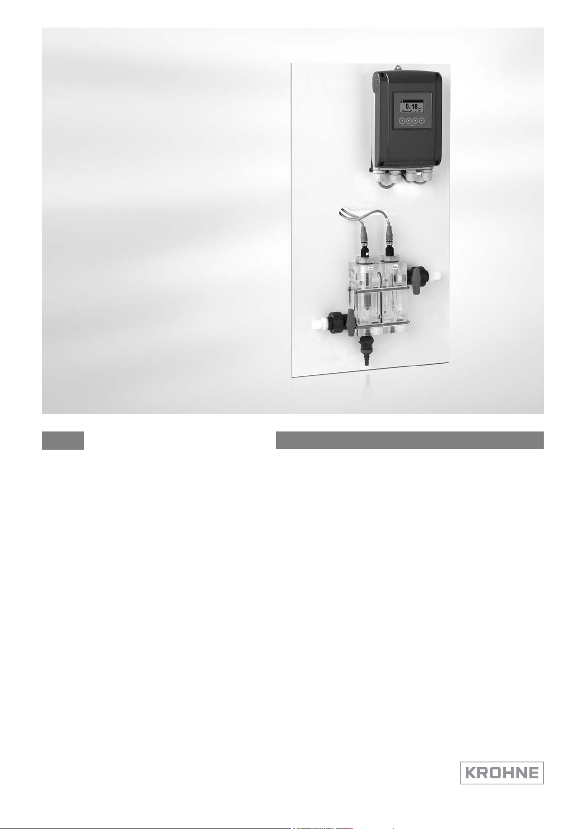
OPTISYS CL 1100
Handbook
Free chlorine/chlorine dioxide/ozone measuring system
The documentation is only complete when used in combination with the relevant
documentation for the signal converter.
© KROHNE 01/2013 - 4002492301 - MA OPTISYS CL 1100 R02 en
Page 2

: IMPRINT :::::::::::::::::::::::::::::::::::::::
All rights reserved. It is prohibited to reproduce this documentation, or any part thereof, without
the prior written authorisation of KROHNE Messtechnik GmbH.
Subject to change without notice.
Copyright 2012 by
KROHNE Messtechnik GmbH - Ludwig-Krohne-Str. 5 - 47058 Duisburg (Germany)
2
www.krohne.com 01/2013 - 4002492301 - MA OPTISYS CL 1100 R02 en
Page 3

OPTISYS CL 1100
CONTENTS
1 Safety instructions 5
1.1 Intended use ..................................................................................................................... 5
1.2 Safety instructions from the manufacturer ..................................................................... 5
1.2.1 Copyright and data protection ................................................................................................ 5
1.2.2 Disclaimer ............................................................................................................................... 6
1.2.3 Product liability and warranty ................................................................................................ 6
1.2.4 Information concerning the documentation........................................................................... 6
1.2.5 Warnings and symbols used................................................................................................... 7
1.3 Safety instructions for the operator................................................................................. 7
2 Device description 8
2.1 Scope of delivery............................................................................................................... 8
2.2 Device description of the system ..................................................................................... 9
2.3 Device description of the sensor.................................................................................... 10
2.4 Nameplate ...................................................................................................................... 10
3 Installation 11
3.1 Notes on installation ......................................................................................................11
3.2 Pre-installation requirements ....................................................................................... 11
3.3 Installing the sensor....................................................................................................... 12
3.3.1 Mounting to OPTISYS CL 1100 measuring system............................................................... 12
3.4 Examples of a typical measuring point.......................................................................... 12
4 Electrical connections 13
4.1 Safety instructions.......................................................................................................... 13
4.2 Connecting the cable to the sensor ............................................................................... 13
4.3 Connecting the sensor cable to the signal converter.................................................... 14
4.4 Connecting the external temperature sensor ............................................................... 15
5 Operation 16
5.1 Menu mode structure..................................................................................................... 16
5.2 Function tables ............................................................................................................... 18
5.2.1 Menu A, quick setup.............................................................................................................. 18
5.2.2 Menu B, test .......................................................................................................................... 19
5.2.3 Menu C, setup ....................................................................................................................... 20
5.3 Calibration ...................................................................................................................... 22
5.3.1 Calibration order................................................................................................................... 22
5.3.2 Temperature compensation .................................................................................................22
5.3.3 pH compensation .................................................................................................................. 25
5.3.4 Calibrating the free chlorine/chlorine dioxide/ozone measurement .................................. 27
5.3.5 Calibration log....................................................................................................................... 32
5.4 Troubleshooting.............................................................................................................. 32
www.krohne.com01/2013 - 4002492301 - MA OPTISYS CL 1100 R02 en
3
Page 4

CONTENTS
OPTISYS CL 1100
6 Service 33
6.1 Maintenance ................................................................................................................... 33
6.1.1 Cleaning ................................................................................................................................ 33
6.1.2 Aging and re-calibration ....................................................................................................... 34
6.2 Spare parts availability...................................................................................................34
6.3 Availability of services .................................................................................................... 34
6.4 Returning the device to the manufacturer..................................................................... 35
6.4.1 General information.............................................................................................................. 35
6.4.2 Form (for copying) to accompany a returned device............................................................ 36
6.5 Disposal .......................................................................................................................... 36
7 Technical data 37
7.1 Measuring principle........................................................................................................37
7.2 Technical data................................................................................................................. 41
7.3 Dimensions and weights for the system........................................................................ 43
7.4 Dimensions for the sensor ............................................................................................. 43
4
www.krohne.com 01/2013 - 4002492301 - MA OPTISYS CL 1100 R02 en
Page 5

OPTISYS CL 1100
1.1 Intended use
CAUTION!
Responsibility for the use of the measuring devices with regard to suitability, intended use and
corrosion resistance of the used materials against the measured fluid lies solely with the
operator.
INFORMATION!
The manufacturer is not liable for any damage resulting from improper use or use for other than
the intended purpose.
The intended use of the OPTISYS CL 1100 system is the measurement of free chlorine, chlorine
dioxide or ozone in water applications.
1.2 Safety instructions from the manufacturer
1.2.1 Copyright and data protection
The contents of this document have been created with great care. Nevertheless, we provide no
guarantee that the contents are correct, complete or up-to-date.
SAFETY INSTRUCTIONS 1
The contents and works in this document are subject to copyright. Contributions from third
parties are identified as such. Reproduction, processing, dissemination and any type of use
beyond what is permitted under copyright requires written authorisation from the respective
author and/or the manufacturer.
The manufacturer tries always to observe the copyrights of others, and to draw on works created
in-house or works in the public domain.
The collection of personal data (such as names, street addresses or e-mail addresses) in the
manufacturer's documents is always on a voluntary basis whenever possible. Whenever
feasible, it is always possible to make use of the offerings and services without providing any
personal data.
We draw your attention to the fact that data transmission over the Internet (e.g. when
communicating by e-mail) may involve gaps in security. It is not possible to protect such data
completely against access by third parties.
We hereby expressly prohibit the use of the contact data published as part of our duty to publish
an imprint for the purpose of sending us any advertising or informational materials that we have
not expressly requested.
www.krohne.com01/2013 - 4002492301 - MA OPTISYS CL 1100 R02 en
5
Page 6

1 SAFETY INSTRUCTIONS
1.2.2 Disclaimer
The manufacturer will not be liable for any damage of any kind by using its product, including,
but not limited to direct, indirect or incidental and consequential damages.
This disclaimer does not apply in case the manufacturer has acted on purpose or with gross
negligence. In the event any applicable law does not allow such limitations on implied warranties
or the exclusion of limitation of certain damages, you may, if such law applies to you, not be
subject to some or all of the above disclaimer, exclusions or limitations.
Any product purchased from the manufacturer is warranted in accordance with the relevant
product documentation and our Terms and Conditions of Sale.
The manufacturer reserves the right to alter the content of its documents, including this
disclaimer in any way, at any time, for any reason, without prior notification, and will not be liable
in any way for possible consequences of such changes.
1.2.3 Product liability and warranty
The operator shall bear responsibility for the suitability of the device for the specific purpose.
The manufacturer accepts no liability for the consequences of misuse by the operator. Improper
installation and operation of the devices (systems) will cause the warranty to be void. The
respective "Standard Terms and Conditions" which form the basis for the sales contract shall
also apply.
OPTISYS CL 1100
1.2.4 Information concerning the documentation
To prevent any injury to the user or damage to the device it is essential that you read the
information in this document and observe applicable national standards, safety requirements
and accident prevention regulations.
If this document is not in your native language and if you have any problems understanding the
text, we advise you to contact your local office for assistance. The manufacturer can not accept
responsibility for any damage or injury caused by misunderstanding of the information in this
document.
This document is provided to help you establish operating conditions, which will permit safe and
efficient use of this device. Special considerations and precautions are also described in the
document, which appear in the form of underneath icons.
6
www.krohne.com 01/2013 - 4002492301 - MA OPTISYS CL 1100 R02 en
Page 7
OPTISYS CL 1100
1.2.5 Warnings and symbols used
Safety warnings are indicated by the following symbols.
DANGER!
This information refers to the immediate danger when working with electricity.
DANGER!
This warning refers to the immediate danger of burns caused by heat or hot surfaces.
DANGER!
This warning refers to the immediate danger when using this device in a hazardous atmosphere.
DANGER!
These warnings must be observed without fail. Even partial disregard of this warning can lead to
serious health problems and even death. There is also the risk of seriously damaging the device
or parts of the operator's plant.
SAFETY INSTRUCTIONS 1
WARNING!
Disregarding this safety warning, even if only in part, poses the risk of serious health problems.
There is also the risk of damaging the device or parts of the operator's plant.
CAUTION!
Disregarding these instructions can result in damage to the device or to parts of the operator's
plant.
INFORMATION!
These instructions contain important information for the handling of the device.
LEGAL NOTICE!
This note contains information on statutory directives and standards.
• HANDLING
This symbol designates all instructions for actions to be carried out by the operator in the
specified sequence.
i RESULT
This symbol refers to all important consequences of the previous actions.
1.3 Safety instructions for the operator
WARNING!
In general, devices from the manufacturer may only be installed, commissioned, operated and
maintained by properly trained and authorized personnel.
This document is provided to help you establish operating conditions, which will permit safe and
efficient use of this device.
www.krohne.com01/2013 - 4002492301 - MA OPTISYS CL 1100 R02 en
7
Page 8
2 DEVICE DESCRIPTION
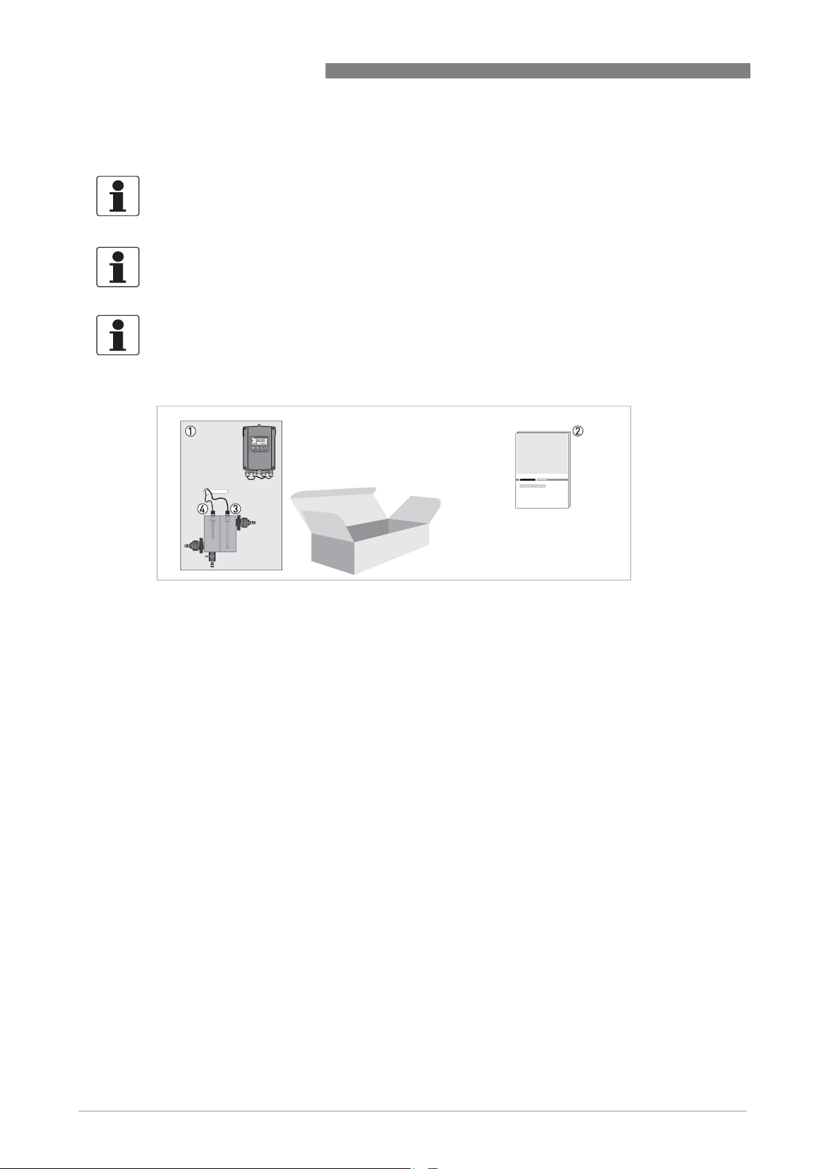
2.1 Scope of delivery
INFORMATION!
Inspect the cartons carefully for damages or signs of rough handling. Report damage to the
carrier and to the local office of the manufacturer.
INFORMATION!
Do a check of the packing list to make sure that you have all the elements given in the order.
INFORMATION!
Look at the device nameplate to ensure that the device is delivered according to your order.
Check for the correct supply voltage printed on the nameplate.
OPTISYS CL 1100
Figure 2-1: Standard scope of delivery
1 Ordered system
2 Documentation
3 OPTISENS CL 1100
4 Temperature sensor
Optional accessories
• Flow-through holder
• Sampling point
• Flow monitor
• Temperature sensor
• Automatic sensor cleaning (ASR, Patent Dr. A. Kuntze).
Consumables/Spare parts available
• OPTISENS CL 1100 sensor (Cl2)
• OPTISENS CL 1100 sensor (ClO
• OPTISENS CL 1100 sensor (O
)
2
)
3
8
www.krohne.com 01/2013 - 4002492301 - MA OPTISYS CL 1100 R02 en
Page 9
OPTISYS CL 1100
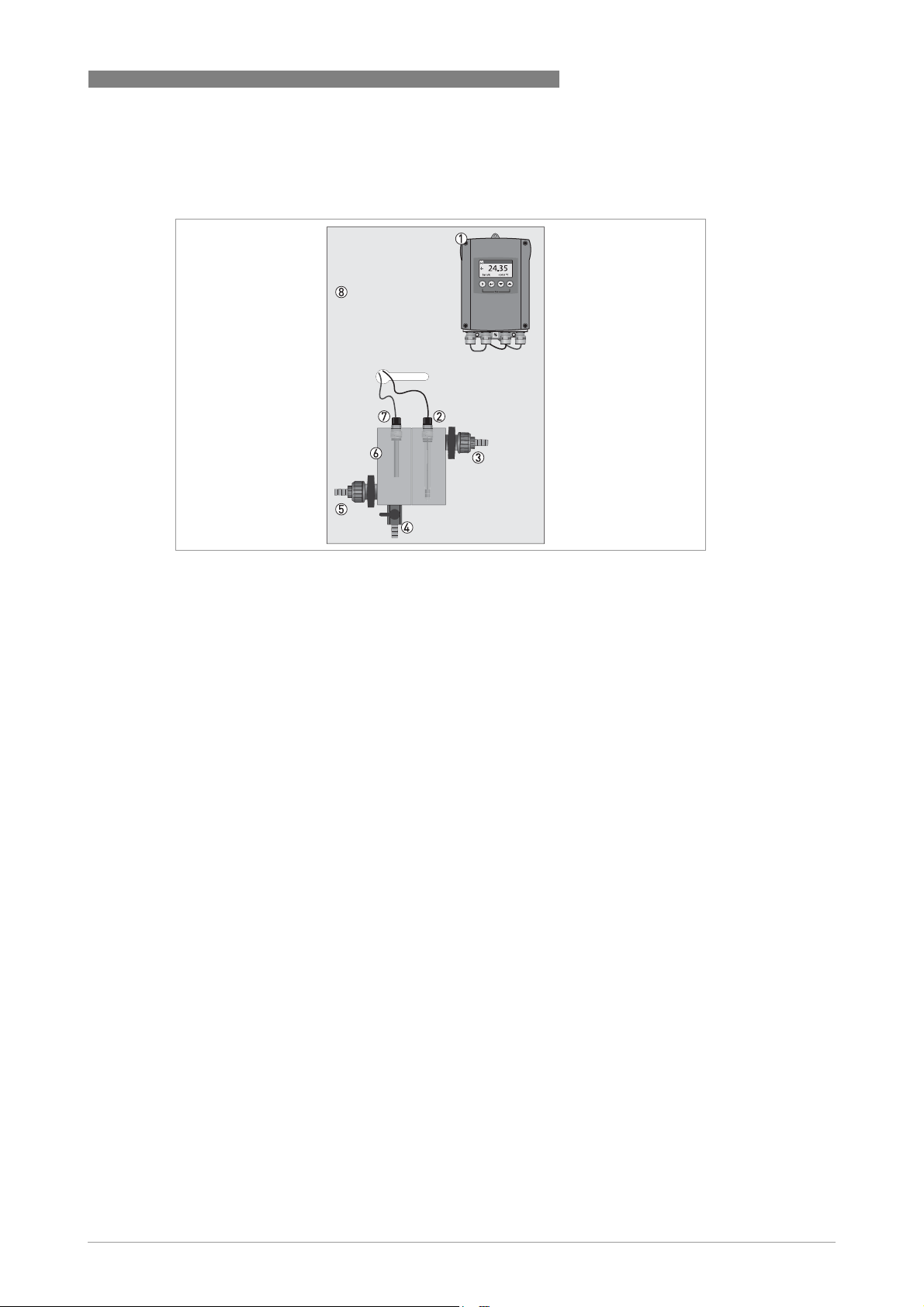
2.2 Device description of the system
DEVICE DESCRIPTION 2
Figure 2-2: Dimension of OPTISYS CL 1100
1 MAC 100 converter
2 OPTISENS CL 1100 sensor with sensor cable CL-W 1100
3 Outlet
4 Sampling point
5 Inlet
6 Flow-through holders
7 Temperature sensor with sensor cable
8 Wall panel
The system for measuring free chlorine, chlorine dioxide or ozone is a ready to use and tested
measuring system with integrated temperature sensor for compensation. As an option a pH
measurement can be added as well as the Automatic Sensor Cleaning (ASR, Patent Dr. A.
Kuntze). The sensors have to be installed and calibrated before use.
www.krohne.com01/2013 - 4002492301 - MA OPTISYS CL 1100 R02 en
9
Page 10
2 DEVICE DESCRIPTION
2.3 Device description of the sensor
The sensor for measuring free chlorine, chlorine dioxide or ozone is characterised by a robust
design and extremely low maintenance requirements. The sensor comprise double gold
electrodes and a low maintenance gel filling. The sensor measurement is virtually flow
independent above 30 l/h / 7.93 gal/h, the optimum is a stable flow between 50...150 l/h /
13.21...39.63 gal/h.
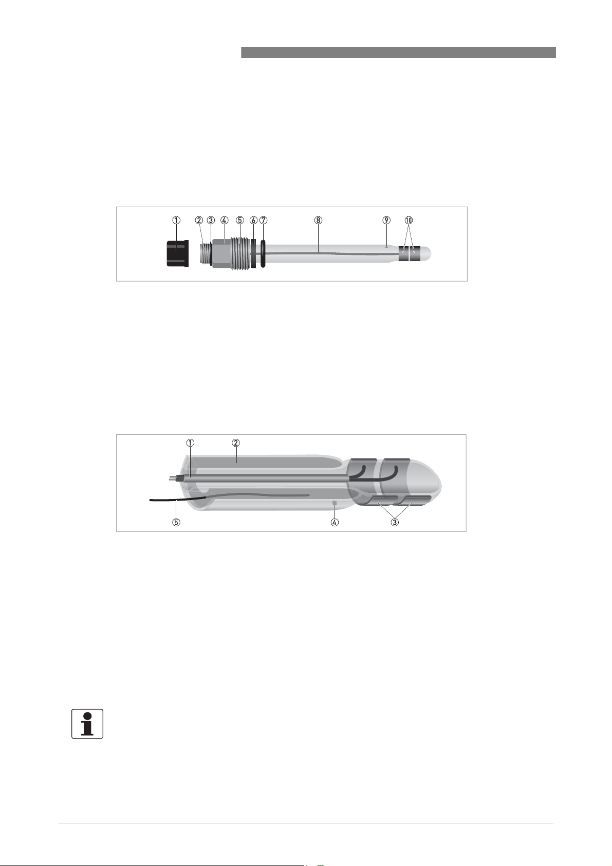
Figure 2-3: Overview of the sensor
1 Protective cap over electrical connector
2 Electrical connector
3 O-ring
4 Hexagonal nut to screw in sensor by hand
5 Sensor thread
6 Washer
7 O-ring
8 Glass tube
9 Diaphragm
10 Gold electrode
OPTISYS CL 1100
Figure 2-4: Inner parts of the sensor
1 Connections of the measuring and counter electrode in the inner glass tube
2 Gel filling of the outer glass tube
3 Measuring and counter electrode (gold)
4 Diaphragm
5 Reference electrode
The sensor is equipped with the patented Automatic Sensor Cleaning (ASR, Patent Dr. A.
Kuntze). An electrochemical process causes outgassing on the gold electrodes, dissolving even
tough coatings such as lime deposits. The ASR considerably increases the life span of the
sensors, achieving high measuring stability with extremely low maintenance requirements.
2.4 Nameplate
INFORMATION!
Look at the device nameplate to ensure that the device is delivered according to your order.
Check for the correct supply voltage printed on the nameplate.
The system type is specified on the labelling of the measuring system package and on the
measuring system itself.
10
www.krohne.com 01/2013 - 4002492301 - MA OPTISYS CL 1100 R02 en
Page 11
OPTISYS CL 1100
3.1 Notes on installation
INFORMATION!
Inspect the cartons carefully for damages or signs of rough handling. Report damage to the
carrier and to the local office of the manufacturer.
INFORMATION!
Do a check of the packing list to make sure that you have all the elements given in the order.
INFORMATION!
Look at the device nameplate to ensure that the device is delivered according to your order.
Check for the correct supply voltage printed on the nameplate.
3.2 Pre-installation requirements
CAUTION!
•
Do not touch or scratch the gold electrodes of the sensor.
•
Make sure that the gold electrodes are clean and dust-free. If necessary, clean the tip as
described on page 33
.
INSTALLATION 3
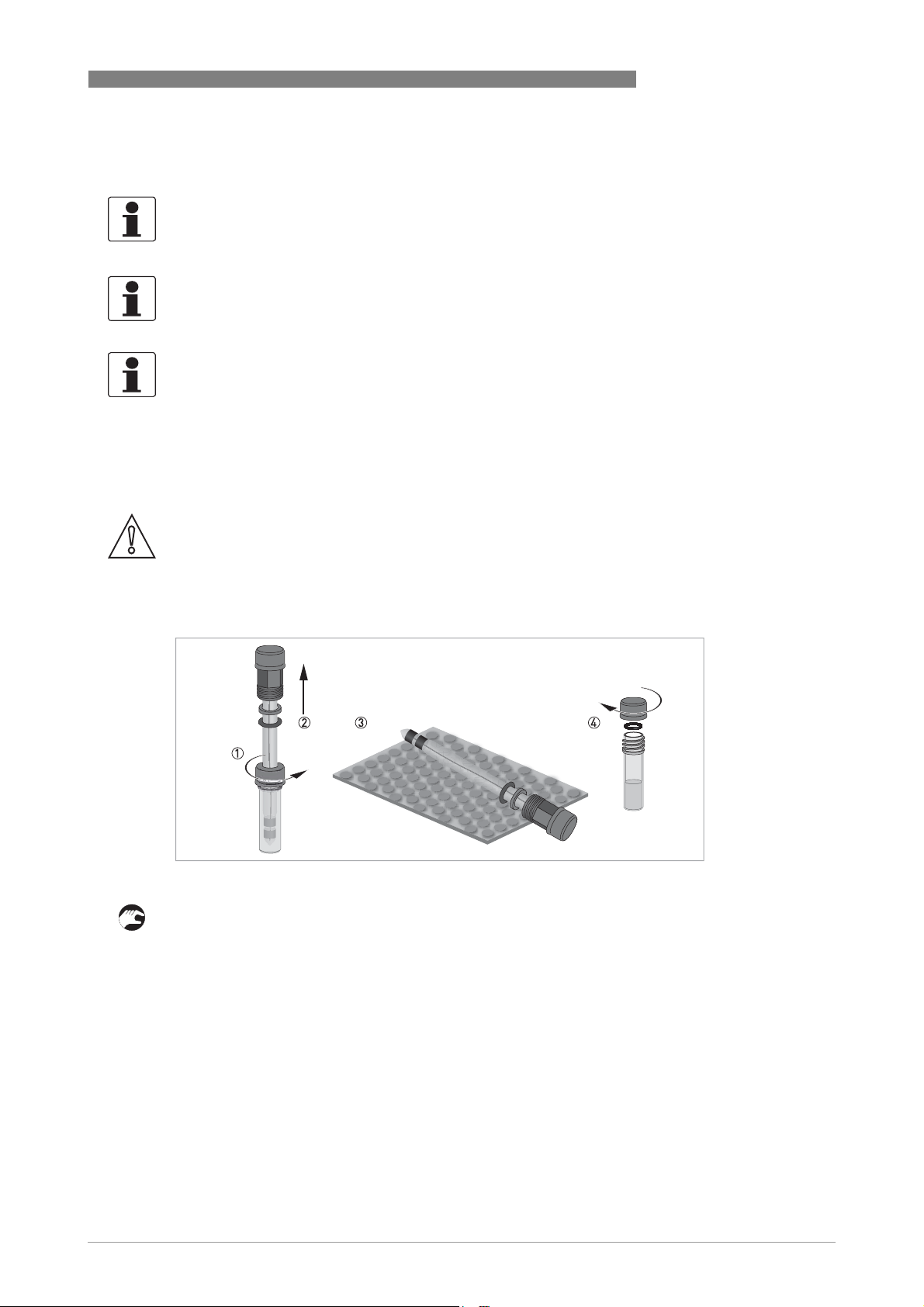
Figure 3-1: Handling the sensor
Unpacking the sensor
• Loosen the storage cap which is screwed on to the plastic tube 1.
• Gently pull the sensor out of the plastic tube 2.
• Lay the sensor on a soft mat/tissue 3.
• Screw the provided sealing cap on to the plastic tube, using O-ring and washer as pictured in
the drawing 4. Keep the storage cap (the one with the hole in it) in the original packing.
www.krohne.com01/2013 - 4002492301 - MA OPTISYS CL 1100 R02 en
11
Page 12
3 INSTALLATION
3.3 Installing the sensor
3.3.1 Mounting to OPTISYS CL 1100 measuring system
The measuring system is delivered ready-to-use. It can be mounted in a distance of 20 mm /
0.79" to a wall via 4 predrilled holes.
Water connection
Connect the water inlet on the left side and the outlet on the right side of the flow cell. The outlet
can be an open outlet (pressureless) or the water can be re-directed into a pipe or basin.
CAUTION!
Install the device at a place where mechanical and chemical stress is limited.
Mind the ingress ptotection: IP 65 (with closed terminal cover)
CAUTION!
The sensors are delivered with protective caps, which have to be removed before mounting into
the flow cell.
OPTISYS CL 1100
3.4 Examples of a typical measuring point
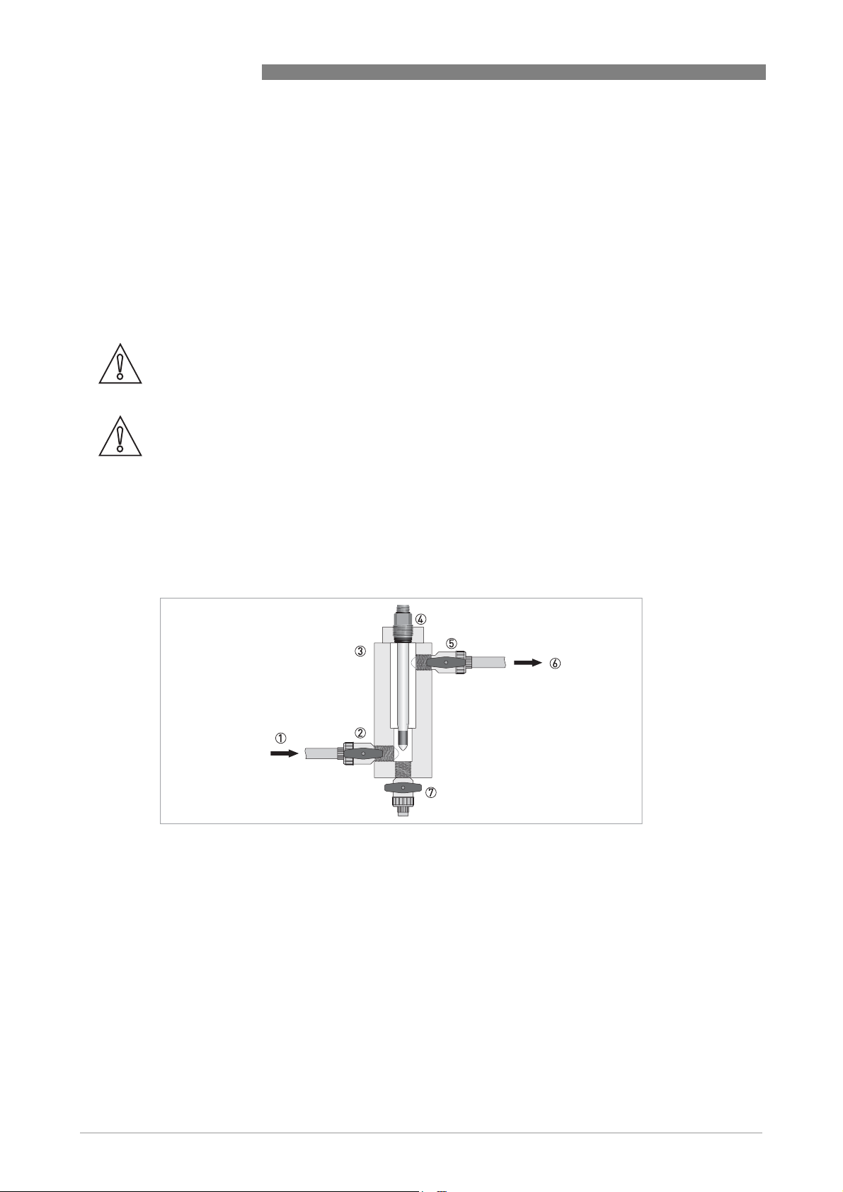
The following drawing show an example of a typical measuring point consisting of a sensor and
the flow-through holder.
Figure 3-2: Measuring point using the flow cell of the OPTISYS CL 1100 measuring system
1 Inlet
2 Inlet valve
3 Flow cell of the OPTISYS CL 1100 measuring system
4 Sensor with connection to signal converter
5 Outlet valve
6 Outlet
7 Sample outlet
12
www.krohne.com 01/2013 - 4002492301 - MA OPTISYS CL 1100 R02 en
Page 13
OPTISYS CL 1100
4.1 Safety instructions
DANGER!
All work on the electrical connections may only be carried out with the power disconnected. Take
note of the voltage data on the nameplate!
DANGER!
Observe the national regulations for electrical installations!
WARNING!
Observe without fail the local occupational health and safety regulations. Any work done on the
electrical components of the measuring device may only be carried out by properly trained
specialists.
INFORMATION!
Look at the device nameplate to ensure that the device is delivered according to your order.
Check for the correct supply voltage printed on the nameplate.
ELECTRICAL CONNECTIONS 4
4.2 Connecting the cable to the sensor
CAUTION!
Avoid moisture inside the sensor connection. If moisture has entered the connector, clean it with
pure water and then dry it with air (e.g. hair blower).
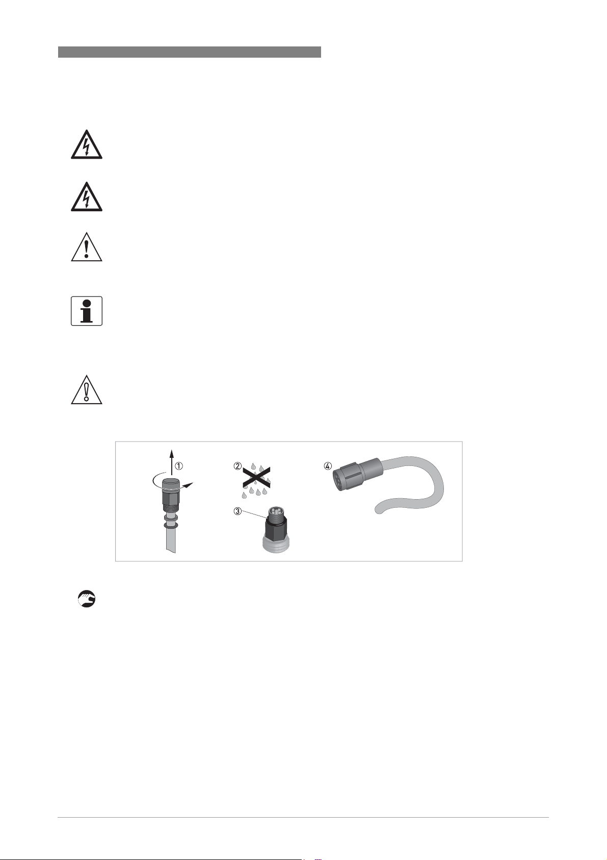
Figure 4-1: Connecting the cable to the sensor
• Unscrew the protective cap from the sensor connector and keep it for future use 1.
• Ensure that both cable and sensor connector are dry 2.
• Make sure that the O-ring is positioned on the sensor connector 3.
• Push the cable connector 4 on to the sensor.
• Screw the cable connector to the sensor and tighten it by hand.
www.krohne.com01/2013 - 4002492301 - MA OPTISYS CL 1100 R02 en
13
Page 14
4 ELECTRICAL CONNECTIONS
4.3 Connecting the sensor cable to the signal converter
DANGER!
All work on the electrical connections may only be carried out with the power disconnected. Take
note of the voltage data on the nameplate!
INFORMATION!
Look at the device nameplate to ensure that the device is delivered according to your order.
Check for the correct supply voltage printed on the nameplate.
OPTISYS CL 1100
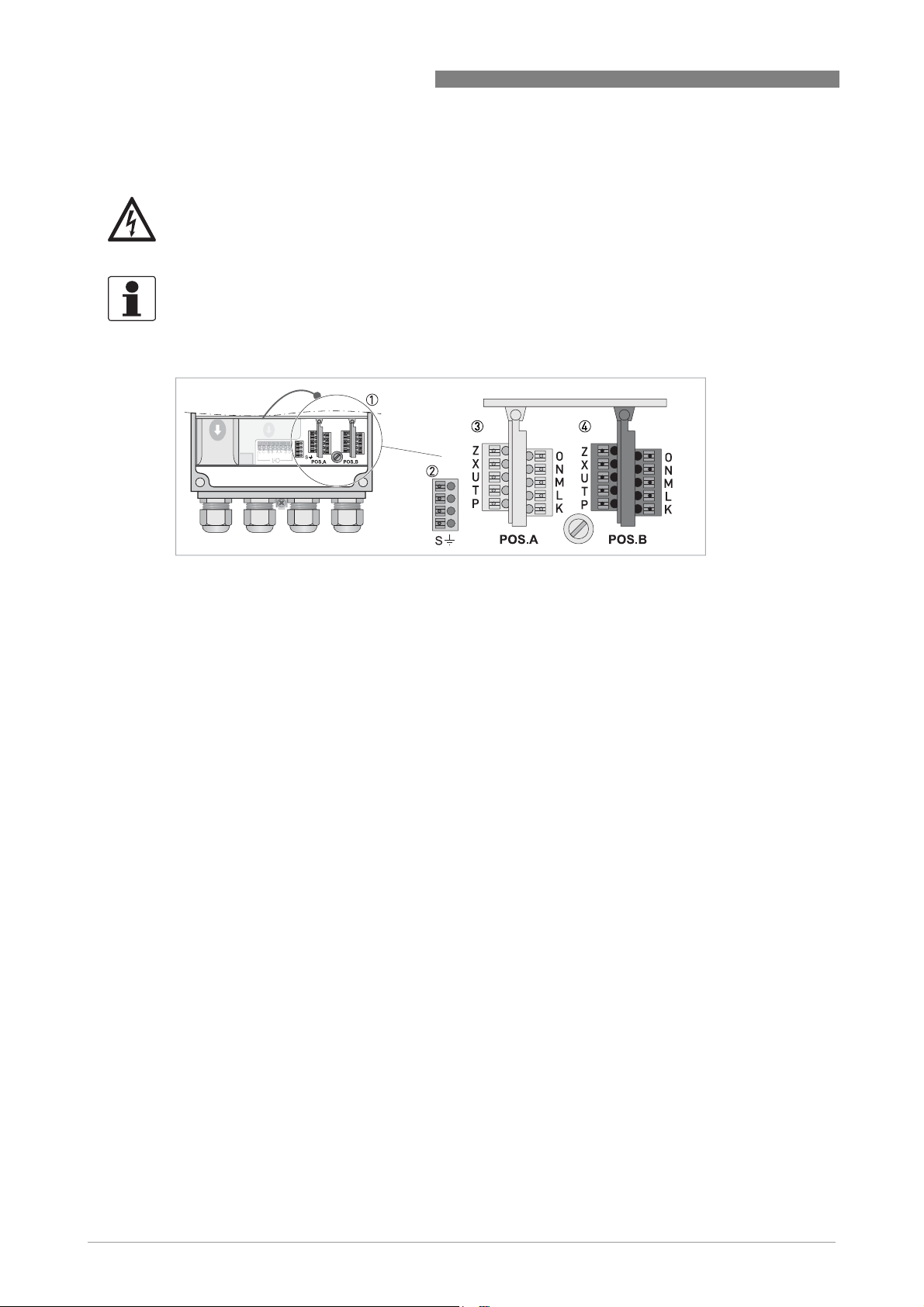
Figure 4-2: Sensor connection terminals on the signal converter
1 Sensor connection terminals
2 Terminal block S (protective earth)
3 Terminal block Pos.A: terminal for OPTISENS CL 1100 sensor and temperature
4 Terminal block Pos.B: terminal for pH sensor and temperature
The sensors for free chlorine, chlorine dioxide or ozone are always connected to terminal block
Pos.A of the signal converter. Depending on the configuration of the signal converter, a pH
sensor may be connected to terminal block Pos.B. An external temperature sensor may be
connected to terminal block Pos.A. (For detailed information how to install and configure a pH
and/or a temperature sensor please refer to the pH sensor documentation.)
14
www.krohne.com 01/2013 - 4002492301 - MA OPTISYS CL 1100 R02 en
Page 15

OPTISYS CL 1100
Figure 4-3: Connecting the 4-wire coax cable
Connecting the sensor cable to the signal converter
• Thread the sensor cable through the middle right cable gland 1.
• Push the coax shield cable 6 into one of the terminals of terminal block S 2.
• Push the blue 3, white 4, and brown 5 wire into the terminals of terminal block Pos.A as
described in the previous drawing/table.
• To remove a cable, press down the white clip 7 on the corresponding terminal and pull the
cable out.
ELECTRICAL CONNECTIONS 4
Cl
4.4 Connecting the external temperature sensor
Connect an external Pt100 or Pt1000 sensor to terminal block Pos.A/B of the signal converter
according to the following drawings:
Figure 4-4: Connection of an external Pt100/1000 temperature sensor to the signal converter
1 2-wire connection
2 3-wire connection
www.krohne.com01/2013 - 4002492301 - MA OPTISYS CL 1100 R02 en
15
Page 16

5 OPERATION
5.1 Menu mode structure
INFORMATION!
The following table just presents an overview. When programming the device, always consult the
function tables additionally as they contain further information!
Only the sensor relevant menus are shown in the following tables. For detailed information
about the general setting refer to the signal converter manual.
OPTISYS CL 1100
Measuring
mode
3 or 4
pages,
scrolling
with ↓ or ↑
Main menu Submenu Parameter
>2.5s^A quick setup >^A9 product cal.A
process input A
product
calibration
(Cl2/ClO2/O3)
A12 REDOX
calibration B
Only if switched
to ORP!
process input B
REDOX
calibration (for 2
channel version;
refer to pH/ORP
sensor
documentation
for further
information)
A13 pH cal. B
process input B
pH calibration
(for 2 channel
version; refer to
pH/ORP sensor
documentation
for further
information)
↓↑ ↓↑ ↓↑ ↓↑
>2.5s^B test >^B1 sim.process
inp.A
B2 sim.process
inp.B
B3 simulation I/O B3.1 current out A
>^A9.1 temp.comp. >^For further
A9.4 pH compensation
A9.6 start calib.
A9.7 stored value
A9.8 reference
A13.1 temp.comp.
>^B1.1 temperature >^For further
B1.4 conc.absolute
B2.1 temperature
B2.5 REDOX/ORP
Only if switched to ORP!
(for 2 channel version; refer to
pH/ORP sensor documentation
for further information)
B2.7 pH
(for 2 channel version; refer to
pH/ORP sensor manual for
further information)
B3.2 current out B
B3.3 current out C
B3.6 simulation R3 off
information
see function
tables.
information
see function
tables.
16
www.krohne.com 01/2013 - 4002492301 - MA OPTISYS CL 1100 R02 en
Page 17

OPTISYS CL 1100
OPERATION 5
Measuring
mode
Main menu Submenu Parameter
B4 actual values B4.1 operating hours
B4.2 process input A
B4.2.1 temperature
B4.2.6 concentration
(Cl2/ClO2/O3)
B4.2.9 CPU temp. (depends on V
number)
B4.2.11 electrode current (µA)
B4.3 process input B
B4.3.1 temperature
B4.3.2 pH
B4.3.9 CPU temp. (depends on V
number)
B4.3.11 elctrode current (μA)
B5 logbooks B5.1 status log
B5.2 calibration log
B6 information B6.1 C number
B6.2 process input A
B6.3 process input B
B6.4 SW.REV.MS
B6.5 SW.REV.UIS
B6.6 Electronic Revision ER
↓↑ ↓↑ ↓↑ ↓↑
www.krohne.com01/2013 - 4002492301 - MA OPTISYS CL 1100 R02 en
17
Page 18

5 OPERATION
OPTISYS CL 1100
Measuring
mode
3 or 4
pages,
scrolling
with ↓ or ↑
Main menu Submenu Parameter
>2.5s^C setup >^C1 process input A>^C1.1 parameter >^For further
C1.9 slope
C1.11 pH compensation
C1.13 cleaning
C1.14 time constant
C1.15 temperature
C1.18 product cal.
C2 process input
B (for 2 channel
version; refer to
pH/ORP sensor
manual for
further
information)
↓↑ ↓↑ ↓↑ ↓↑
C2.1 parameter (pH/REDOX)
C2.7 inner buffer (only pH)
C2.8 zero point
C2.9 slope
C2.10 calibration buffer (only
pH)
C2.14 time constant
C2.15 temperature (only pH)
C2.16 REDOX cal.
C2.17 pH cal.
information
see function
tables.
5.2 Function tables
5.2.1 Menu A, quick setup
INFORMATION!
Note that the appearance of some sub-menus depends on the hardware setting and the used
sensor(s). Also only the sensor relevant menus and submenus are shown here in detail. For all
other menu functions refer to the MAC 100 documentation .
A9, process input A product calibration (Cl2/ClO2/O3)
For 1 or 2 channel version: Settings for sensor calibration
A12, process input B REDOX calibration
For 2 channel version; refer to pH/ORP sensor manual for further information.
Only if switched to ORP!
A13, process input B pH calibration
For 2 channel version; refer to pH/ORP sensor manual for further information.
18
www.krohne.com 01/2013 - 4002492301 - MA OPTISYS CL 1100 R02 en
Page 19

OPTISYS CL 1100
5.2.2 Menu B, test
INFORMATION!
Note that the appearance of some sub-menus depends on the hardware setting and the used
sensor(s). Also only the sensor relevant menus and sub-menus are shown here in detail. For all
other menu functions refer to the converter manual.
The procedure to start the simulation process is the same for all functions:
• Choose the function with the help of ↓ or ↑ and press ^.
i You see the two options "set value" (opens the editor to enter the simulation value) and
"break" (exits the menu without simulation).
• Choose the desired option with the help of ↑ or ↓ and press ^.
i If you chose "set value", the device asks "start simulation?" and offers the options "no"
(exits the menu without simulation) or "yes" (starts the simulation finally).
• Choose the desired option with the help of ↑ or ↓ and press ^.
i If you chose "yes", the simulation starts.
OPERATION 5
B1, sim.process inp.A B2, sim.process inp.B
Level Designation / function Settings / descriptions
B1.1
B2.1
B1.4
B2.4
B2.5 REDOX/ORP In this menu the relative concentration of REDOX/ORP can be simulated. For
B2.7 pH In this menu the relative concentration of pH can be simulated. For 2
temperature In this menu the temperature can be simulated.
conc.absolute In this menu the concentration can be simulated.
2 channel version only; refer to pH/ORP sensor manual for further
information. ONLY if switched to ORP.
channel version only; refer to pH/ORP sensor manual for further
information.
B4, actual values
Level Designation / function Settings / descriptions
This menu groups several functions which allow to display the corresponding actual reading. The shown measurements
are depending on the device configuration.
B4.1 operating hours This menu shows the operating time of the devices in hours.
B4.2 process input A In this menu the measurements from process input A can be read.
B4.3 process input B In this menu the measurements from process input B can be read.
For 2 channel version only; refer to pH/ORP sensor manual for further
information.
www.krohne.com01/2013 - 4002492301 - MA OPTISYS CL 1100 R02 en
19
Page 20

5 OPERATION
OPTISYS CL 1100
5.2.3 Menu C, setup
INFORMATION!
The signal converter has two process inputs, A and B. Each process input has an own submenu
in this main menu. Process input A is always present, i.e. there is always a board in the interface
"Pos.A" in the connection area. The interface of process input B only has a board with the two
channel signal converter. Be aware that the definition which kind of measurement a process
input can do is defined when ordering the device. The configuration cannot be changed later.
INFORMATION!
Note that the appearance of some submenus depends on the hardware setting and the used
sensor(s).
C1, process input A C2, process input B
Level Designation / function Settings / descriptions
Process input A and B can be either a sensor 1 or a sensor 2. Further information about the type of sensor 1 or 2 please
refer to MAC 100 manual "Sensor input combinations". Process input A is always present, process Input B can be
present.
Note: The exchange of a sensors 1 with a sensor 2, or vice versa, can only be done by the manufacturer!
Depending on the sensor which is connected to a slot A or B the menu changes.
C1.1 parameter (Cl2/ClO2/O3) This menu item is for selecting the probe which is connected to process
C1.9 slope This menu item is read only.
C1.11 pH compensation The pH compensation menu is used for calibration of the pH sensor. For
input A. The entries of this selection depends on the chosen device
configuration. The device configuration is customer specific and set during
production.
It is used for the calibration procedure.
detailed information refer to
Options:
pH compensation
on page 25.
• off (default setting): pH compensation is disabled
• manual: pH influences are compensated with manually entered values
• automatic: pH influences are compensated automatically using the value
from a pH sensor which is connected to input B
C1.12 man. pH compensation If in menu C1.11 the pH compensation was set to manual, here the desired
C1.13 cleaning In this menu the cleaning parameters are set.
C1.13.1 cleaning Options:
pH value is entered manually.
For detailed information and the cleaning procedure refer to
page 33.
Cleaning
on
• off: cleaning is disabled
• 24h period: cleaning is performed every 24 hours. (once a day)
• 12h period: cleaning is performed every 12 hours.
• 8h period: cleaning is performed every 8 hours.
C1.13.2 start time Time:
C1.13.3 clean hold [s] Hold time [s] after cleaning. If measurement after cleaning has not
Time of day: cleaning is started at manually entered time.
The start time of the cleaning procedure can be postpone.
approximated to 10% of old value, hold time is retriggered up to two times.
20
www.krohne.com 01/2013 - 4002492301 - MA OPTISYS CL 1100 R02 en
Page 21

OPTISYS CL 1100
OPERATION 5
Level Designation / function Settings / descriptions
C1.13.4 clean Start cleaning procedure, manually.
C1.15
C2.15
C1.15.1
C2.15.1
temperature Menu for temperature measurement. Available for sensor 1 and sensor 2.
probe Options:
• manual: used if no internal or external temperature sensor is connected to
the signal converter
• Pt100: used if the pH sensor has an integrated Pt temperature
measurement or if an external Pt100 temperature sensor is connected to
the signal converter
• Pt1000: used if an external Pt1000 temperature sensor is connected to the
signal converter
C1.15.2
C2.15.2
C1.15.3
C2.15.3
C1.15.4
C2.15.4
C1.15.5
C2.15.5
manual Only available if C1.15.1 or C2.15.1 is set to "manual".
correction Offset correction for temperature measurement. Not available if C1.15.1 or
limitation Measuring ranges for temperature measurement.
temp. comp. Menu for activating the temperature compensation parameters.
C2.15.1 is set to "manual".
For detailed information refer to
Options:
Temperature compensation
on page 22.
• on: linear temperature compensation.
• off: temperature compensation is disabled.
C1.18 product calibration For detailed information refer to
C1.18.1 temp.comp Menu for activating the temperature compensation parameters for the
calibration.
Options:
Calibration
on page 22.
• off: temperature measurement is disabled
• manual: temperature value has to be entered manually
• automatic: temperature measurement is performed as configured
C1.18.2 temperature Menu for setup of manual temperature measurement
C1.18.3 temp. coefficient Temperature coefficient for manual temperature compensation during
C1.18.4 pH compensation Options:
calibration.
• off: pH measurement is disabled
• manual: pH value has to be entered manually
• automatic: pH measurement is performed as configured
C1.18.5 man. pH compensation If in menu C1.18.4 the pH compensation was set to manual, here the desired
C1.18.6 start calibration Start calibration procedure.
C1.18.7 stored value View stored value of calibration.
C1.18.8 reference Enter the reference value of the probe in mg/L.
pH value is entered manually.
CAUTION!
If you choose for measurement the temperature compensation "linear" than choose between
"automatic" or "manual" for the temperature compensation during calibration. If you choose for
measurement the temperature compensation "off" than choose also "off" for the temperature
compensation during calibration.
www.krohne.com01/2013 - 4002492301 - MA OPTISYS CL 1100 R02 en
21
Page 22

5 OPERATION
5.3 Calibration
5.3.1 Calibration order
If you are also measuring the temperature and pH value of the measuring medium, it is essential
to calibrate in the following order, otherwise start with 3. calibrate the sensor:
1. Calibrate temperature measurement as described on the following pages.
2. Calibrate pH measurement (refer to the manual of the pH sensor).
3. Calibrate the sensor as described on the following pages.
5.3.2 Temperature compensation
2 option for temperature compensation during measurement:
• on: linear temperature compensation.
• off: temperature compensation is disabled.
3 option for temperature compensation during calibration:
OPTISYS CL 1100
• automatic: the signal converter will automatically compensate temperature influence using
the information of a Pt100 or Pt1000 temperature sensor.
• manual: the signal converter will compensate temperature influence using a manually
entered value; this option only makes sense if the temperature of the measured medium is
quite constant.
• off: temperature compensation is disabled.
INFORMATION!
•
The measurement is temperature dependent due to the linear temperature compensation.
The linear temperature compensation compensates the influence of the ion velocity.
•
Please note that the temperature sensor should always record the temperature where the
measuring electrodes are exposed.
•
If you activate the temperature c the temperature coefficient can be changed. The presetting
is based on drinking water: 3%/
°
K. You have to change the presetting if the medium is not
drinking water. The coefficient depends on the hardness and the ion velocity of the medium.
•
If you choose no compensation, the measured Cl2, ClO2 or O3 concentration will most likely
deviate from the actual Cl
, ClO2 or O3 concentration. The reason is that the Cl2, ClO2 or O3
2
concentration of a specific medium varies depending on the temperature of the medium.
The menu for the type of linear temperature probes offer the following options:
• Pt1000: choose this option if there is an external Pt1000 temperature sensor connected to the
signal converter.
• Pt100: choose this option if the pH sensor has an integrated Pt100 temperature
measurement or if there is an external Pt100 temperature sensor connected to the signal
converter.
• manual: choose this option if there is no internal or external temperature sensor connected
to the signal converter.
22
www.krohne.com 01/2013 - 4002492301 - MA OPTISYS CL 1100 R02 en
Page 23

OPTISYS CL 1100
After starting-up the signal converter, the measuring screen appears. This is the standard
screen which is displayed automatically in the normal operating mode. If you are in this mode
and you want to adjust the temperature compensation, you have to perform the following steps:
Step 1: activating the temperature compensation for measurement
Press > for more than 2.5 seconds, then release the button. You are now on the main menu level. In the
upper line on the right side of the display "A" appears, beneath the main menu quick setup is highlighted.
Press or until the main menu setup is highlighted.
OPERATION 5
MAIN MENU
A quick setup
B test
> C setup
D service
Press > to enter the chosen menu.
You are on the first submenu level. In the upper line of the display "setup" and "C1"
appears, beneath the submenu process input A is highlighted.
Press > to enter the chosen menu.
You are on the second submenu level. In the submenu parameter
(Cl2/ClO2/O3) is highlighted.
Use or until the submenu temperature is highlighted.
Press > to enter the chosen menu.
You are on the parameter level. In the upper line of the display
"temperature" and "C1.15.1" or "C2.15.1"appears, beneath the option
probe is highlighted.
Use or until the menu item temp. comp. is highlighted.
Press > to enter the chosen menu.
Now you can set up the temperature compensation.
Press or to choose between on and off.
Press ^ to confirm the entered value.
If you have chosen the option linear, you can select the type of
temperature compensation now.
Press or until menu item temp.coefficient is highlighted.
Enter the value and press ^ to confirm the value.
Press or to choose probe.
Press > to enter the chosen menu.
Press or to choose between Pt1000, Pt100 or
manual.
Press ^ to confirm the entered value.
Press ^ several time until you reach the measuring mode again. Choose yes to safe and confirm
your selection.
Step 2: Configure/adjust the temperature sensor for measurement
Step 2a: probe Pt100 or Pt1000:
Read the currently measured temperature of the Pt100 / Pt1000 temperature sensor from the
measurement screen and write it down.
Measure the temperature with a reference thermometer and check if it deviates from the temperature
measured by the Pt100 / Pt1000.
Press > for more than 2.5 seconds, then release the button. You are now on the main menu level.
Press or until the main menu setup is highlighted.
www.krohne.com01/2013 - 4002492301 - MA OPTISYS CL 1100 R02 en
23
Page 24

5 OPERATION
Press ^ to confirm the entered value. The temperature sensor has been adjusted.
If necessary, enter the temperature correction in Kelvin so that the signal converter shows the
same temperature as the reference thermometer.
OPTISYS CL 1100
MAIN MENU
A quick setup
B test
> C setup
D service
Press > to enter the chosen menu.
You are on the first submenu level. In the upper line of the display "SETUP"
and "C1" appears, beneath the submenu process input A is highlighted.
Press > to enter the chosen menu process input A.
Press or until the main menu temperature is highlighted.
Press > to enter the chosen menu. The submenu probe Pt100 / 1000 is
highlighted.
Press or until the submenu correction is highlighted.
Press > to enter the chosen menu.
INFORMATION!
A separate temperature sensor has to be connected to "Pos.A" and configurated on process
input A.
24
www.krohne.com 01/2013 - 4002492301 - MA OPTISYS CL 1100 R02 en
Page 25

OPTISYS CL 1100
Step 2b: probe manual:
Measure the temperature of the measuring medium.
Press > for more than 2.5 seconds, then release the button. You are now on the main menu level.
Press or until the main menu setup is highlighted.
OPERATION 5
MAIN MENU
A quick setup
B test
> C setup
D service
Press > to enter the chosen menu.
You are on the first submenu level. In the upper line of the display "SETUP"
and "C1" appears, beneath the submenu process input A is highlighted.
Press > to enter the chosen menu process input A.
Press or until the submenu temperature is highlighted.
Press > to enter the chosen menu. The submenu probe manual is
highlighted.
Press or until the submenu manual is highlighted.
Press > to enter the chosen menu.
Enter the measured temperature.
Press ^ to confirm the entered value. The manually measured temperature will now be used for
temperature compensation.
5.3.3 pH compensation
INFORMATION!
The pH compensation is only necessary for the measurement of free chlorine.
The menu for the pH compensation offers 3 different options:
• automatic: the signal converter compensates pH influences on the free chlorine
measurement automatically using the value from a pH sensor connected to input B. This
allows a stable free chlorine measurement in water with changing pH values. Though this
kind of compensation can neither change the effect that the signal output decreases at higher
pH values nor that the disinfection ability of free chlorine decreases with increasing
pH values. As a principle the manufacturer recommends an automatic compensation if the
pH value of the measured medium is between pH 8 and 8.5 with temporal variations.
• manual: the signal converter compensates pH influences using a manually entered value.
This kind of compensation makes sense if you know the pH value, if it is stable and outside
the neutral range.
• off (default setting): the pH compensation is disabled. This option makes sense if the pH value
is more or less stable or in the neutral range (around pH 7). If the pH compensation is
disabled and you use a reference method (like DPD) which compensates the pH influence,
you calibrate this difference in. Hence if the pH value now changes, the calibration is not valid
anymore. However for slight pH changes around pH 7 this effect is only marginal, but for
drastic changes a new calibration is necessary. If those changes happen frequently, you
should select one of the other compensation methods.
www.krohne.com01/2013 - 4002492301 - MA OPTISYS CL 1100 R02 en
25
Page 26

5 OPERATION
DANGER!
Whenever you change the compensation method, a recalibration of the sensor input is
necessary. Otherwise the device displays a wrong measured value. If you use this wrong
measured value for dosing of disinfecting agents, this could result in fatal injuries.
INFORMATION!
Also note the following items concerning the pH compensation:
•
If you choose an automatic pH compensation for input A, you should calibrate the pH sensor
connected to input B before you choose this kind of compensation. Therefore refer to the
manual of the pH sensor.
•
Both the automatic and the manual function compensate the displayed value of the free
chlorine concentration to 100% HOCl at pH = 6.0. Hence for a correct calibration the
reference value should compensate the pH value in the same manner.
•
Keep in mind that if you use a pH sensor connected to input B, it has to be re-calibrated in
regular intervals.
•
For additional information concerning the effect of the pH value refer to Measuring principle
on page 37
OPTISYS CL 1100
.
Please consider that you can activate the pH compensation for measurement and separably for
the calibration.
After starting-up the signal converter, the measuring screen appears. This is the standard
screen which is displayed automatically in the normal operating mode. If you are in this mode
and you want to adjust the pH compensation, you have to perform the following steps:
Step 1: activating the pH compensation for measurement
Press > for more than 2.5 seconds, then release the button. You are on the main menu level. In the upper
line of the display "A" appears, beneath the main menu quick setup is highlighted.
Press or until the main menu setup is highlighted.
MAIN MENU
A quick setup
B test
> C setup
D service
Press > to enter the chosen menu.
You are on the first submenu level. In the upper line of the display "setup" and "C1"
appears, beneath the submenu process input A is highlighted.
Press > to enter the chosen menu.
Press or until the submenu pH compensation is highlighted.
Press > to enter the chosen menu.
Press or to choose between "automatic", "manual" or "off".
Press ^ to confirm the entered value.
26
If you want to return to the measuring mode, press ^ several times.
www.krohne.com 01/2013 - 4002492301 - MA OPTISYS CL 1100 R02 en
Page 27

OPTISYS CL 1100
OPERATION 5
Step 2: entering a pH value manually
• If you have activated the manual pH compensation as described in the previous step, you can
enter a pH value using or .
• Press ^ to confirm the value.
i The manually entered pH value will be used for pH compensation.
• If you want to return to the measuring mode, press ^ several times.
5.3.4 Calibrating the free chlorine/chlorine dioxide/ozone measurement
Calibration is necessary in regular intervals or when installing a new sensor.
INFORMATION!
When calibrating a free chlorine/chlorine dioxide/ozone measurement, keep in mind that the
measuring system as a whole is calibrated, and not only the sensor. Therefore the measuring
system has to be re-calibrated if, for example, the measuring medium changes.
To avoid alarms on the distributed control system (DLC) when temporary removing the sensor
(i.e. for maintenance), the signal converter has a hold function. This function "freezes" all
outputs (i.e. the display and the current outputs) on the last measured value.
INFORMATION!
As an indication that the manual hold function is active, the "warning sign" in the upper left
corner of the display appears. Meanwhile the status messages show "checks in progress".
After starting-up the signal converter, the measuring screen appears. This is the standard
screen which is displayed automatically in the normal operating mode. If you are in this mode
and you want to initiate a calibration, you have to activate the manual hold function performing
the following steps:
www.krohne.com01/2013 - 4002492301 - MA OPTISYS CL 1100 R02 en
27
Page 28

5 OPERATION
Step 1: activating the manual hold function
Press > for more than 2.5 seconds, then release the button.
You are on the main menu level. In the upper line on the right side of the display "A" appears, beneath the
main menu quick setup is highlighted.
You have activated the manual hold function. To perform the next step and prepare the
calibration procedure you have to return to the measuring mode.
Press ^ until you reach the measuring mode again.
OPTISYS CL 1100
MAIN MENU
> A quick setup
B test
C setup
D service
Press > to enter the chosen menu.
You are on the first submenu level. In the upper line of the display "quick
setup" and "A1" appears, beneath the submenu language is highlighted.
Press or until the submenu manual hold is highlighted.
Press > to enter the chosen menu.
You are on the parameter level. The option off is highlighted.
Press or to choose the option on.
Press ^ to confirm your selection.
Step 2: preparing the calibration procedure
• If you calibrate a new sensor, make sure that the sensor is correctly connected to the signal
converter.
• Check the sensor for damages or dirt deposits.
• During the calibration procedure, you will have to take a sample. Provide a suitable sample
vessel.
28
www.krohne.com 01/2013 - 4002492301 - MA OPTISYS CL 1100 R02 en
Page 29

OPTISYS CL 1100
After activating the manual hold function and the preparative measures, you can get access to
the calibration procedure from the measuring mode in two different ways. Either you go via the
main menu setup (Step 3a) or via the main menu quick setup (Step 3b):
Step 3a: accessing the calibration menu via the main menu "setup"
Press > for more than 2.5 seconds, then release the button. You are on the main menu level. In the upper
line of the display "A" appears, beneath the main menu quick setup is highlighted.
Press or until the main menu setup is highlighted.
MAIN MENU
A quick setup
B test
> C setup
D service
Press > to enter the chosen menu.
You are on the first submenu level. In the upper line of the display "setup"
and "C1" appears, beneath the submenu process input A is highlighted.
Press > to enter the chosen menu.
You are on the second submenu level. The submenu
parameter is highlighted.
Press > to enter the chosen menu.
OPERATION 5
Press or to select Cl2 for calibrating the
free chlorine measurement, ClO
the chlorine dioxide measurement or O3 for
calibrating the ozon measurement.
Press ^ to confirm the entered value.
Press or until the submenu product cal. is
highlighted.
for calibrating
2
You can start the calibration procedure now as described in "Step 4".
Step 3b: accessing the calibration menu via the main menu "quick setup"
Press > for more than 2.5 seconds, then release the button. You are on the main menu level. In the upper
line of the display "A" appears, beneath the main menu quick setup is highlighted.
MAIN MENU
> A quick setup
B test
C setup
D service
Press > to enter the chosen menu.
You are on the first submenu level. In the upper line of the display "quick
setup" and "A" appears, beneath the submenu language is highlighted.
Press or until the submenu product cal. A is highlighted.
Press > to enter the chosen menu.
You can start the calibration procedure now as described in "Step 4".
www.krohne.com01/2013 - 4002492301 - MA OPTISYS CL 1100 R02 en
29
Page 30

5 OPERATION
CAUTION!
When calibrating the Cl
configurated.
Step 4: calibration procedure
• After choosing the submenu product cal. (step 3a) or product cal. A (step 3b) in the previous
steps, continue by pressing >.
i The signal converter demands to choose the kind of temperature compensation for
calibration. You have the options "automatic", "manual" and "off" (for detailed information
refer to
• If you chose "automatic", just press ^. If you chose "manual", first enter the temperature of
the measured medium using or and then press ^.
i The signal converter demands to choose the kind of pH compensation. You have the
following options: "automatic", "manual" and "off" (for detailed information refer to
compensation
• If you chose "automatic", just press ^. If you chose "manual", first enter the pH value of the
measured medium using or and then press ^.
• Press or until the submenu start calib.highlighted .
Press > to enter the chosen menu
i The measured value appears on the display.
measurement, the temperature and pH compensation have to be
2
Temperature compensation
on page 25).
OPTISYS CL 1100
on page 22).
pH
• Assure that the measured medium flows with at least 30 litres per hour; if necessary wait until
the measured value is stable.
• Once the measured value is stable, press ^ and wait 25 seconds.
i The signal converter now asks store value?
• Choose yes using or and then press ^.
i The signal converter now performs a measurement which takes 25 seconds. Carry out the
next action during this time.
To perform a successful calibration please consider the installation of the sensor (for detailed
information refer to
1. Mounting in an outlet pipe
You can start with the calibration. While the signal converter performs a measurement
(25 seconds), take a sample of the measured medium. Determine the free chlorine/chlorine
dioxide/ozon concentration in a laboratory using the DPD method according to
DIN EN ISO 7393 - 2. If the laboratory test is not possible immediately, you can leave the
calibration menu and go back into the measuring mode (the measured value at the time of taking
the sample is stored and can be checked in the menu point "stored value").
2. Mounting in a bypass or direct pipe
Before starting the calibration procedure close the outlet valve and open the probe valve to take
a sample. Proceed as mentioned under "1. Mounting in an outlet pipe".
Installing the sensor
on page 12).
30
INFORMATION!
The "stored value" is a calculated value based on the actual measurement. The signal converter
calculates this value depending on the compensation methods (pH and temperature
compensation) chosen for the calibration. Do not change the compensation method in the time
between the measurement of the "stored value" and the input of the reference value. Otherwise
this could result in a wrong calibration.
www.krohne.com 01/2013 - 4002492301 - MA OPTISYS CL 1100 R02 en
Page 31

OPTISYS CL 1100
Completing the calibration procedure
• As soon as the laboratory value has been determined, go again into the calibration menu and
submenu reference by using or and then press >.
• Enter the laboratory value using or and press ^.
i The signal converter now matches the "stored value" to the laboratory value and makes a
• Assure that the slope of a new sensor is 50...150 mg/nA, otherwise the sensor has a
malfunction. Press ^ if the slope is okay.
i The signal converter now asks store value?
• Using or choose yes to store the calibration values or no to discard them.
• Press ^ to confirm.
• Press ^ several times until the questions appears if the configuration should be stored.
• Using or choose yes to store the configuration or no to discard it.
i You have completed the sensor calibration.
INFORMATION!
If an error occurs during the calibration procedure, the signal converter displays an error
message. Possible causes for an error:
OPERATION 5
re-calibration. The slope appears on the display and it is stored in the calibration logbook
(this helps to compare the slope values over the time when re-calibrating).
•
Slope too flat.
•
Sensor too old.
•
Wrong electrical connection.
Step 5: switching back to measurement
• Deactivate the function "manual hold" again.
www.krohne.com01/2013 - 4002492301 - MA OPTISYS CL 1100 R02 en
31
Page 32

5 OPERATION
5.3.5 Calibration log
INFORMATION!
In order to show the history of the calibrations, the signal converter has a calibration logbook
function. Up to 64 entries of the calibration history are stored including date and time.
Accessing the calibtration log
• Press > for more than 2.5 seconds, then release the button. You are on the main menu level. In the
upper line of the display "A" appears, beneath the main menu quick setup is highlighted.
• Press or until the main menu test is highlighted.
MAIN MENU
A quick setup
> B test
C setup
D service
Press > to enter the chosen menu.
OPTISYS CL 1100
You are on the first submenu level. In the upper line of the display "test" and "B1" appears,
beneath the submenu sim.process input A is highlighted.
Press or until the submenu logbooks is highlighted.
Press > to enter the chosen menu.
You are on the second submenu level. In the upper line of the display "logbooks" and
"B1" appears, beneath the submenu status log is highlighted.
Press or until the submenu calibration log is highlighted.
Press > to enter the chosen menu.
• You are on the data level and you see the calibration history. With the help of or you can
scroll through the different entries.
• If you want to return to the measuring mode press ^ several times until you reach this mode.
5.4 Troubleshooting
Problem Possible cause Remedy
The measurement is inaccurate. This is probably due to coatings
The sensor slope appears to be
too small.
on the electrodes.
The sensor needs to be cleaned.
Use automatic sensor cleaning
or, if this does not help, clean the
electrodes with a soft cloth. For
further information refer to
Cleaning
on page 33.
32
www.krohne.com 01/2013 - 4002492301 - MA OPTISYS CL 1100 R02 en
Page 33

OPTISYS CL 1100
6.1 Maintenance
6.1.1 Cleaning
The sensor can be equipped with the patented automatic sensor cleaning (ASR, patent Dr. A.
Kuntze). An electrochemical process causes outgassing on the measuring electrodes, which can
dissolve even tough coatings such as lime deposits or grease. The ASR considerably increases
the maintenance interval of the sensor. This way, the sensor can stay in the measuring medium
until it reaches the end of its lifetime.
SERVICE 6
Figure 6-1: Automatic sensor cleaning ASR
1 Ceramic diaphragm
2 Gold electrodes
3 Dirt deposits removed by ASR
Configuring automatic sensor cleaning
• Choose setup > process input A > cleaning > cleaning 24 h periode.
• Select a cleaning period of 24 hours (once a day), 12 hours, or 8 hours (three times a day). To
deactivate automatic sensor cleaning, select off.
i The cleaning period starts at the time of configuration.
• If required, you can postpone the start time of the cleaning procedure (setup > process input A
> cleaning > start time) and adjust the hold time after each cleaning procedure ( setup >
process input A > cleaning > hold time [s]). During the hold time, the sensor value is frozen by
the signal converter.
• The cleaning procedure may also be started manually anytime by choosing setup > process
input A > cleaning > clean.
INFORMATION!
Example: It was 3.00 pm when you configured automatic sensor cleaning with 24 hours as
cleaning period. As a result, the sensor will be cleaned once a day at 3.00 pm.
If you have specified a value in the start time submenu, for example "5", the cleaning time will be
postponed by 5 hours. The senor now is cleaned once a day at 8.00 pm.
If necessary, the gold electrodes can be cleaned with a soft cloth. Mechanical cleaning should
not be performed too often since this will disturb the polarisation layer of the sensor.
www.krohne.com01/2013 - 4002492301 - MA OPTISYS CL 1100 R02 en
33
Page 34

6 SERVICE
6.1.2 Aging and re-calibration
CAUTION!
The life time expectation of the sensor depends on the application. Normally, the life time lies
between 2 and 4 years.
In applications with high reliability requirements, e.g. drinking water, we recommend replacing
the sensor once a year.
The sensor has to be re-calibrated in regular intervals due to aging effects of the reference
electrode.For detailed information refer to
calibrating the sensor every 3 months.
When the sensor becomes too old to provide reliable measurements, the signal converter
displays an error message after the calibration procedure. In this case, the sensor has to be
exchanged.
Aging effects
Change of slope due to aging of the reference electrode: An optimal slope value is 100 mg/nA
(new sensor). When the sensor ages, this value changes. When the slope exceeds or falls below
certain limits, an error message is displayed and the sensor has to be exchanged.
The slope of the sensor and the sensor limits are displayed after each calibration procedure.
Calibration
OPTISYS CL 1100
on page 22. We recommend re-
INFORMATION!
It is helpful to note the sensor slope after each calibration procedure. This way you can compare
the slope over the sensor lifetime.
6.2 Spare parts availability
The manufacturer adheres to the basic principle that functionally adequate spare parts for each
device or each important accessory part will be kept available for a period of 3 years after
delivery of the last production run for the device.
This regulation only applies to spare parts which are subject to wear and tear under normal
operating conditions.
6.3 Availability of services
The manufacturer offers a range of services to support the customer after expiration of the
warranty. These include repair, maintenance, technical support and training.
INFORMATION!
For more precise information, please contact your local sales office.
34
www.krohne.com 01/2013 - 4002492301 - MA OPTISYS CL 1100 R02 en
Page 35

OPTISYS CL 1100
6.4 Returning the device to the manufacturer
6.4.1 General information
This device has been carefully manufactured and tested. If installed and operated in accordance
with these operating instructions, it will rarely present any problems.
CAUTION!
Should you nevertheless need to return a device for inspection or repair, please pay strict
attention to the following points:
•
Due to statutory regulations on environmental protection and safeguarding the health and
safety of our personnel, manufacturer may only handle, test and repair returned devices that
have been in contact with products without risk to personnel and environment.
•
This means that the manufacturer can only service this device if it is accompanied by the
following certificate (see next section) confirming that the device is safe to handle.
CAUTION!
If the device has been operated with toxic, caustic, flammable or water-endangering products,
you are kindly requested:
•
to check and ensure, if necessary by rinsing or neutralising, that all cavities are free from
such dangerous substances,
•
to enclose a certificate with the device confirming that is safe to handle and stating the
product used.
SERVICE 6
www.krohne.com01/2013 - 4002492301 - MA OPTISYS CL 1100 R02 en
35
Page 36

6 SERVICE
6.4.2 Form (for copying) to accompany a returned device
Company: Address:
Department: Name:
Tel. no.: Fax no.:
Manufacturer's order no. or serial no.:
The device has been operated with the following medium:
OPTISYS CL 1100
This medium is: water-hazardous
toxic
caustic
flammable
We checked that all cavities in the device are free from such
substances.
We have flushed out and neutralized all cavities in the
device.
We hereby confirm that there is no risk to persons or the environment through any residual media
contained in the device when it is returned.
Date: Signature:
Stamp:
6.5 Disposal
CAUTION!
Disposal must be carried out in accordance with legislation applicable in your country.
36
www.krohne.com 01/2013 - 4002492301 - MA OPTISYS CL 1100 R02 en
Page 37

OPTISYS CL 1100
7.1 Measuring principle
Free chlorine measurement
TECHNICAL DATA 7
Figure 7-1: Free chlorine measurement
1 Reference electrode
2 Voltage measurement
3 Current needed to maintain the constant potential
4 Counter electrode
5 Measuring electrode
The sensor has three electrodes: a measuring electrode (gold), a counter electrode (gold), and a
reference electrode (Ag/AgCl). A precise potential is built up between the measuring and the
counter electrode. The measuring electrode starts polarising, i.e. negative charges collect close
to the measuring electrode. After polarisation the electrical current decreases to 0 mA as long
as the polarising layer is not changed.
Free chlorine molecules that hit the surface of the measuring electrode take a defined portion of
the charge with them, changing the potential of the measuring potential. The signal converter
constantly measures the potential between measuring and reference electrode and immediately
readjusts the potential as soon as it begins to change. The current needed to maintain a constant
potential is directly correlated to the free chlorine concentration in the measuring medium.
www.krohne.com01/2013 - 4002492301 - MA OPTISYS CL 1100 R02 en
37
Page 38

7 TECHNICAL DATA
Free chlorine (chlorine dissolved in water) changes its chemical composition depending on the
pH value of the water. The pH value has consequences for the disinfection strength: with
increasing pH the disinfection strength decreases.
OPTISYS CL 1100
• below pH3: Chlorine gas Cl
2
• between pH3 and pH8: Hypochlorous acid HOCl
• above pH8: Hypochlorite ClO
Figure 7-2: Composition of free chlorine depending on pH value
In order to obtain a reliable free chlorine measurement you should either control or compensate
the pH value of the measuring medium. Because the pH measurement is temperature
dependent, it also makes sense to measure the temperature. For further information on
installing a pH sensor with temperature measurement, refer to the pH sensor manual.
38
www.krohne.com 01/2013 - 4002492301 - MA OPTISYS CL 1100 R02 en
Page 39

OPTISYS CL 1100
Chlorine dioxide measurement
Figure 7-3: Chlorine dioxide measurement
1 Reference electrode
2 Voltage measurement
3 Current needed to maintain the constant potential
4 Counter electrode
5 Measuring electrode
TECHNICAL DATA 7
Chlorine dioxide measurement
Chlorine dioxide (ClO
) is an instable, non-storable, toxic gas with a characteristic scent. The
2
molecule consists of one chlorine atom and two oxygen atoms – represented in the chemical
formula ClO
. It is very reactive. To avoid the risk of spontaneous explosions of gaseous chlorine
2
dioxide or concentrated solutions, it is generally handled in dilution with low concentrations.
ClO
is soluble in water, but tends to evaporate quickly. Typically it is prepared on site, for
2
example from hydrochloric acid and sodium chlorite. The procedure provides solutions with
approx. 2 g/l ClO
The disinfection effect of ClO
chlorinated byproducts are formed. ClO
that can be safely handled and stored for several days.
2
is due to the transfer of oxygen instead of chlorine, so that no
2
is used as disinfectant against biofilm, bacteria, spores,
2
and viruses. Today it is believed that the molecule´s unpaired electron is transferred to the DNA
of the microorganism which cracks and causes cell necrosis. ClO
several days. In contrast to chlorine, the disinfection strength of ClO
has a long-term effect of
2
does not depend on pH,
2
and neither does the measurement show a pH influence in the range of pH 6 to pH 9.
is measured potentiostatic with measuring and counter electrodes of pure gold and an
ClO
2
Ag/AgCl reference. The measurement shows good selectivity towards ClO
. A precise potential is
2
applied to the measuring electrode, leading to an accumulation of negative charges on the metal
surface. ClO
molecules that hit the surface take a defined portion of the charge with them. The
2
controller measures the potential between measuring and reference electrode and readjusts
the charge on the electrode surface. The current necessary to maintain a constant charge is a
direct measure for the concentration of chlorine dioxide.
www.krohne.com01/2013 - 4002492301 - MA OPTISYS CL 1100 R02 en
39
Page 40

7 TECHNICAL DATA
Ozon measurement
Figure 7-4: Ozon measurement
1 Reference electrode
2 Voltage measurement
3 Current needed to maintain the constant potential
4 Counter electrode
5 Measuring electrode
OPTISYS CL 1100
Ozone measurement
Ozone (O
) is an instable molecule of three oxygen atoms and a very strong oxidizing agent. At
3
room temperature it is a gas. Due to its instability it cannot be stored in pressurised cylinders
and has to be prepared on site.
is an eco-friendly disinfectant. However, its great disinfection strength can only be used to
O
3
good advantage in suitable reactors with a sojourn time of at least 3 minutes. The long-term
effect of O
O
is measured potentiostatic with measuring and counter electrodes of pure gold and an
3
is only a few minutes.
3
Ag/AgCl reference. The measurement shows good selectivity towards ozone. A precise potential
is applied to the measuring electrode, leading to an accumulation of negative charges on the
metal surface. O
molecules that hit the surface take a defined portion of the charge with them.
3
The controller measures the potential between measuring and reference electrode and
readjusts the charge on the electrode surface. The current necessary to maintain a constant
charge is a direct measure for the concentration of O
. The sensor design with 3 electrodes in a
3
single rod enables us to use our patented cleaning procedure ASR (patent Dr. A. Kuntze)
providing you with a low-maintenance measuring setup.
40
www.krohne.com 01/2013 - 4002492301 - MA OPTISYS CL 1100 R02 en
Page 41

OPTISYS CL 1100
7.2 Technical data
Technical data for the system
OPTISYS CL 1100
Installation conditions
Installation Wall installation with sample feed
Housing protection
class
Sample flow
connections
Drill Hole 10 mm / 0.39"
Measuring accuracy
Reference
conditions
Maximum
measuring error
Repeatability 0.2% full scale
Resolution 0.1/0.01 mg/l
Long-term stability 24 hours: tested within accuracy definition
Temperature drift Tested within accuracy definition
Cable length
variation
TECHNICAL DATA 7
IP65, Nema 4
Tube connection DN 6/8
Medium: water
Temperature: 20°C/ 68°F
Pressure: 1 bar / 14.5 psi (absolute)
≤ 2% full scale
Temperature: 1.0% full scale
Tested within accuracy definition
Operating conditions
Ambient
temperature
Process
temperature
Max. operating
pressure
Min. flow rate > 30 l/h / 7.93 gal/h
Min. conductivity > 150 μS/cmTD
-15...+55°C / +5...+131°F
0…+50°C / +32…+122°F
4 bar / 58 psi
www.krohne.com01/2013 - 4002492301 - MA OPTISYS CL 1100 R02 en
41
Page 42

7 TECHNICAL DATA
Technical data for the sensor
OPTISYS CL 1100
OPTISENS CL 1100 Cl
2
ClO
2
Measuring system
Measuring principle Potentiostatic with double gold electrodes
Application range Continuous
Measuring range Cl
measurement of free
chlorine in water
applications.
: 0.03…5mg/l ClO2: 0.05…5mg/l O3: 0.05…5mg/l
2
Continuous
measurement of
chlorine dioxide in water
applications.
Design
Construction Glass sensor
Shaft diameter 12 mm / 0.47"
Length 120 mm / 4.72"
Process connection PG 13.5
Sensor cap M12
Materials
Sensor shaft Glass
Measuring electrodes Gold
Reference electrode Ag/AgCl/Tepox gel
Diaphragm Ceramic
Gasket EPDM
O
3
Continuous
measurement of ozon in
water applications.
Electrical connection
Connector M12
For further information about the technical data please consider the OPTISENS CL 1100 manual.
42
www.krohne.com 01/2013 - 4002492301 - MA OPTISYS CL 1100 R02 en
Page 43

OPTISYS CL 1100
7.3 Dimensions and weights for the system
TECHNICAL DATA 7
[mm] [inch]
a 700 27.56
b 400 15.75
c 105.2 4.14
Weight: 5.15 kg / 11.35 lb
7.4 Dimensions for the sensor
Figure 7-5: Dimensions of OPTISENS CL 1100
Dimensions
Dimensions
[mm] [inch]
a 31 1.2
b 120 4.7
c 10 0.4
d Ø12 Ø0.5
www.krohne.com01/2013 - 4002492301 - MA OPTISYS CL 1100 R02 en
43
Page 44

KROHNE product overview
• Electromagnetic flowmeters
• Variable area flowmeters
• Ultrasonic flowmeters
• Mass flowmeters
• Vortex flowmeters
• Flow controllers
• Level meters
• Temperature meters
• Pressure meters
• Analysis products
• Products and systems for the oil & gas industry
• Measuring systems for the marine industry
Head Office KROHNE Messtechnik GmbH
Ludwig-Krohne-Str. 5
47058 Duisburg (Germany)
Tel.:+49 (0)203 301 0
Fax:+49 (0)203 301 10389
info@krohne.de
© KROHNE 01/2013 - 4002492301 - MA OPTISYS CL 1100 R02 en - Subject to change without notice.
The current list of all KROHNE contacts and addresses can be found at:
www.krohne.com
 Loading...