

Page 1
07/2008
Installation and
Operating Instructions
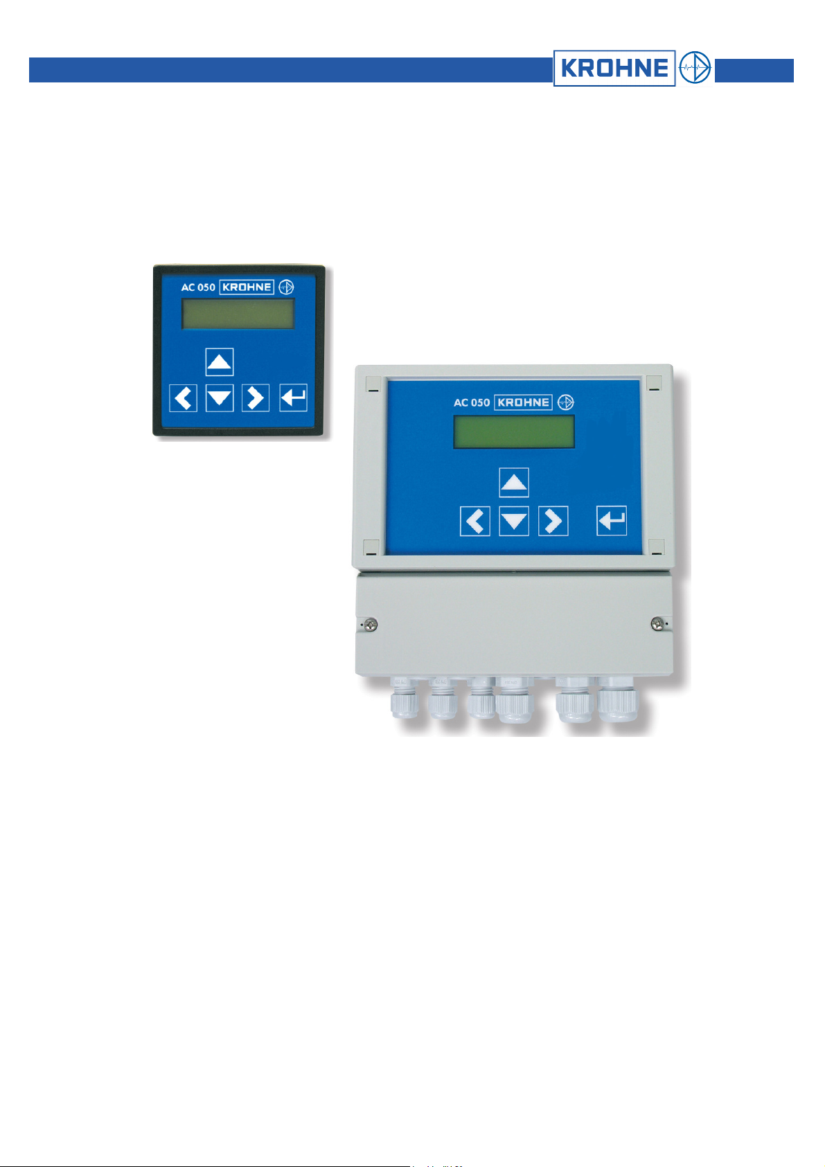
OPTISENS
CAC 050
IAC 050
Measuring and control device
for conductivity measurements
Page 2

Content
Manual OPTISENS CAC 050 / IAC 050
0. Introduction......................................................................................................................................................................................... 3
0.1
General .................................................................................................................................................................................................................. 3
0.2
Legal matters ......................................................................................................................................................................................................... 3
0.3
Safety..................................................................................................................................................................................................................... 4
0.3.1 Documentation symbols......................................................................................................................................................................................... 4
0.4
Features................................................................................................................................................................................................................. 5
0.4.1 Device .................................................................................................................................................................................................................... 5
0.4.2 Controller................................................................................................................................................................................................................ 5
0.4.3 Connections ........................................................................................................................................................................................................... 5
1. Mechanical installation ...................................................................................................................................................................... 6
1.1
Installation of panel-mounting converters .............................................................................................................................................................. 6
1.2
Installation of wall-mounting converters................................................................................................................................................................. 7
2. Electrical connection.......................................................................................................................................................................... 8
2.1
Connection diagram panel-mounting converter..................................................................................................................................................... 9
2.2
Connection diagram wall-mounting enclosure..................................................................................................................................................... 10
3. Operation of the device.................................................................................................................................................................... 11
3.1
How to adjust parameters.................................................................................................................................................................................... 11
3.1.1 Selection between alternatives ............................................................................................................................................................................ 11
3.1.2 Adjustment of numerical parameters ................................................................................................................................................................... 12
3.2
Menu Overview .................................................................................................................................................................................................... 12
3.2.1 Main menu and basic settings ............................................................................................................................................................................. 12
3.3
Password and language ...................................................................................................................................................................................... 13
3.3.1 Enter password .................................................................................................................................................................................................... 13
3.3.2 Language ............................................................................................................................................................................................................. 13
4. Adjustments for the measurement ................................................................................................................................................. 14
4.1
Configuration of the converter.............................................................................................................................................................................. 14
4.2
c value (cell factor)............................................................................................................................................................................................... 15
4.2.1 Calibration via cell factor...................................................................................................................................................................................... 15
4.3
Cable compensation and averaging .................................................................................................................................................................... 16
4.3.1 Cable compensation (zero point correction) ........................................................................................................................................................ 16
4.3.2 Averaging............................................................................................................................................................................................................. 16
4.4
Temperature compensation................................................................................................................................................................................. 16
4.4.1 Calibration of the temperature measurement ...................................................................................................................................................... 17
4.4.2 Temperature coefficient ....................................................................................................................................................................................... 17
5. Adjustments of the controller.......................................................................................................................................................... 17
5.1
ON/OFF controller................................................................................................................................................................................................ 18
5.2
P / PI controller as impulse-frequency controller ................................................................................................................................................. 18
5.3
P / PI controller as pulse-pause controller ........................................................................................................................................................... 19
5.4
Activation and deactivation of the controller ........................................................................................................................................................ 20
5.5
Turn-on delay....................................................................................................................................................................................................... 20
5.6
External controller stop ........................................................................................................................................................................................ 20
5.7
Manual operation of the relays............................................................................................................................................................................. 21
5.8
Limit values .......................................................................................................................................................................................................... 22
5.8.1 Turn-on delay....................................................................................................................................................................................................... 22
5.9
Dosage check ...................................................................................................................................................................................................... 22
6. Alarm.................................................................................................................................................................................................. 23
6.1
Error messages.................................................................................................................................................................................................... 24
7. Output................................................................................................................................................................................................ 24
7.1
Current output ...................................................................................................................................................................................................... 25
7.2
Serial interface RS485 (option)............................................................................................................................................................................ 25
8. Operation and maintenance ............................................................................................................................................................ 25
8.1
Maintenance of the device................................................................................................................................................................................... 25
8.2
Display contrast ................................................................................................................................................................................................... 25
8.3
Exchange fuse ..................................................................................................................................................................................................... 25
8.4
Cleaning............................................................................................................................................................................................................... 25
8.5
Maintenance of the conductivity measurement ................................................................................................................................................... 26
8.6
Disposal ............................................................................................................................................................................................................... 26
8.7
Service ................................................................................................................................................................................................................. 26
8.7.1 Product info.......................................................................................................................................................................................................... 26
8.7.2 Analog inputs ....................................................................................................................................................................................................... 26
OPTISENS CAC 050 / IAC 050 2
Page 3

Manual OPTISENS CAC 050 / IAC 050
8.7.3 Erase settings (reset)........................................................................................................................................................................................... 26
9. Technical data................................................................................................................................................................................... 27
9.1
Technical data...................................................................................................................................................................................................... 27
9.2
Dimensions .......................................................................................................................................................................................................... 28
9.2.1 Panel-mounting enclosure ................................................................................................................................................................................... 28
9.2.2 Wall-mounting enclosure ..................................................................................................................................................................................... 28
10. Device return form............................................................................................................................................................................ 29
11. Customer settings - for reference ................................................................................................................................................... 30
0. Introduction
0.1 General
This manual applies to the following devices:
It contains technical information for the installation, start-up and maintenance. If you have any questions not
0.2 Legal matters
Device and type revision date
CAC 050 R 09/07
CAC 050 W 09/07
IAC 050 R 09/07
IAC 050 W 09/07
included in this manual please contact your supplier or the official representative of KROHNE Water Solutions
in your country.
Authorized personnel
Installation, connection, adjustment, start-up, and maintenance of the device are carried out by authorized
personnel with adequate qualification.
Liability
Responsibility as to suitability and intended use of these devices rests solely with the user. Improper
installation and operation may lead to loss of warranty. In addition, KROHNE Group's Standard General
Conditions of Sale and Delivery, found on the back of the invoice and forming the basis of the purchasing
contract, are applicable.
General limitation on liability
Unless otherwise expressly set forth in the Standard Terms and Conditions of Sale and Delivery, the Seller is
only liable for damages, whatever their legal basis is, in case they are based on willful action or gross
negligence. This limitation on liability does not apply in the event the Buyer raises claims relating to personal
injury or damages to property according to the product liability law based on a defect of the delivered goods.
Any advice given by the Seller, in particular regarding the application of the delivered goods, shall only commit
the Seller if given or confirmed in writing.
Returning the device
If you need to return the level gauge to the manufacturer or supplier, please read to the instructions and
complete the form given in the appendix.
Warranty
Please consult KROHNE Water Solutions General Terms and Conditions for information on guarantee and
liability.
3 OPTISENS CAC 050 / IAC 050
Page 4
0.3 Safety
0.3.1 Documentation symbols
Please check for damages immediately after receiving the devices and report any damages within 24 hours to
the delivering company. Never work with a damaged device.
Keep this manual at a safe place where you can always look up the safety instructions and the information on
handling and usage.
This device was designed and built according to the safety measurements for electronic devices and has left
our company in perfect working condition. To preserve this condition and to ensure safe usage follow all
instructions carefully and pay special attention to all warnings issued in this manual. If the device is visibly
damaged or has been stored inappropriately or if there are any doubts concerning safe usage, shut it down
and make sure it cannot be restarted by accident.
A set of symbols is used to give warnings or information relevant to particular applications. These are defined
below:
Caution / Attention
Information that, if not followed, may lead to actions resulting in incorrect functioning of the device.
Warning
Information that, if not followed, may lead to actions resulting in measurement error, personal injury and/or
NOTE
damage to the device.
Is used to highlight interesting details.
Manual OPTISENS CAC 050 / IAC 050
OPTISENS CAC 050 / IAC 050 4
Page 5

Manual OPTISENS CAC 050 / IAC 050
0.4 Features
0.4.1 Device
Cell factor (recommendation)
0.4.2 Controller
0.4.3 Connections
Measuring ranges
conductive
Measuring ranges
inductive
Measuring range temperature -30.0…+140.0°C
Display Measured value with dimension
Temperature compensation manually or automatically with Pt100 or NTC
Set points 2 set points with adjustable direction
Controller types ON/OFF controller with hysteresis
Hysteresis adjustable within the measuring range
P range XP adjustable within the measuring range
Integral time TN 0…2000 s
Least pulse 0.1…9.9 s
Pulse+ pause time 02…99 s
Impulse frequency 00…72 equiv. to 0...7200 pulses/h
Turn-on delay 0…200 s
Alarm function min. and max. limit and onset delay, power failure alarm,
Dosage control 0…2000 s
Relays 3 potential-free contacts (2x controller, 1x alarm)
Analog outputs 2x 0/4…20 mA galvanically isolated
Analog inputs 1 measuring input for conductivity sensor
Digital input external controller stop or lack-of-water indication
Serial interface (Option) RS485, Baud rate 9600, data format 8 Bit,
0.00…20.00 MΩ/cm c = 0.05/cm
0.000…2.000 µS/cm c = 0.05/cm
0.00…20.00 µS/cm c = 0.05/cm
0.0…200.0 µS/cm c = 0.05/cm
0.000…2.000 mS/cm c = 0.2/cm
0.00…20.00 mS/cm c = 1/cm
0.0…200.0 mS/cm c = 10/cm
0.00…2.00 mS/cm c see measuring cell
0.,0…200.0 mS/cm c see measuring cell
0…2000 mS/cm c see measuring cell
Temperature with dimension
Status display sensor, controller & alarm
P controller as Pulse-Pause-, Impulse-Frequency- or steady controller
PI controller as Pulse-Pause-, Impulse-Frequency- or steady controller
6 A, 250 V, max. 550 VA
max. loading 500 Ohm
1 measuring input for Pt100 or NTC
1start and 1stop bit, no parity
5 OPTISENS CAC 050 / IAC 050
Page 6
1. Mechanical installation
On Chapter 9.2 you will find detailed instructions for the installation.
For panel-type meters you have to prepare an opening of 92 x 92 mm / 3.6” x 3.6”. Install the device and fix it
with the two mounting clips which were part of the delivery.
You can install devices in wall-mounting enclosures either by hanging them upon the center slot or by sliding
the slot under a screw, which is an alternative for limited space. Either way you have to fix it additionally with
two screws.
Install the device in a place where it is not put under mechanical or chemical strain!
ATTENTION
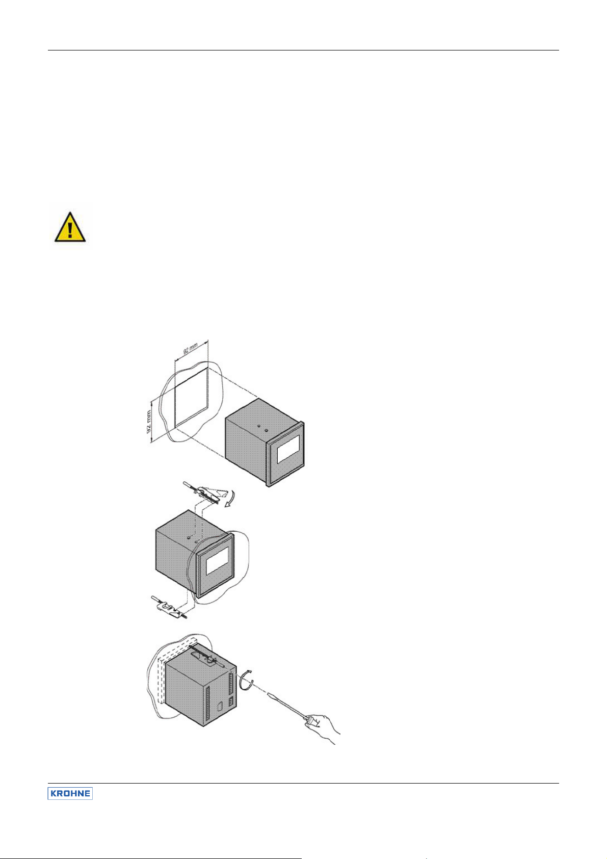
1.1 Installation of panel-mounting converters
Mind the protection class:
• Panel mounting version: IP 54 (front), IP 30 (Housing)
• Wall mounting version: IP 65 (closed terminal cover)
Prepare an opening of 92 x 92 mm / 3.6” x 3.6”.
Install the device from the front side and fix it with the
two mounting clips which were part of the delivery.
Screw tight until the device is fixed perfectly.
Manual OPTISENS CAC 050 / IAC 050
OPTISENS CAC 050 / IAC 050 6
Page 7
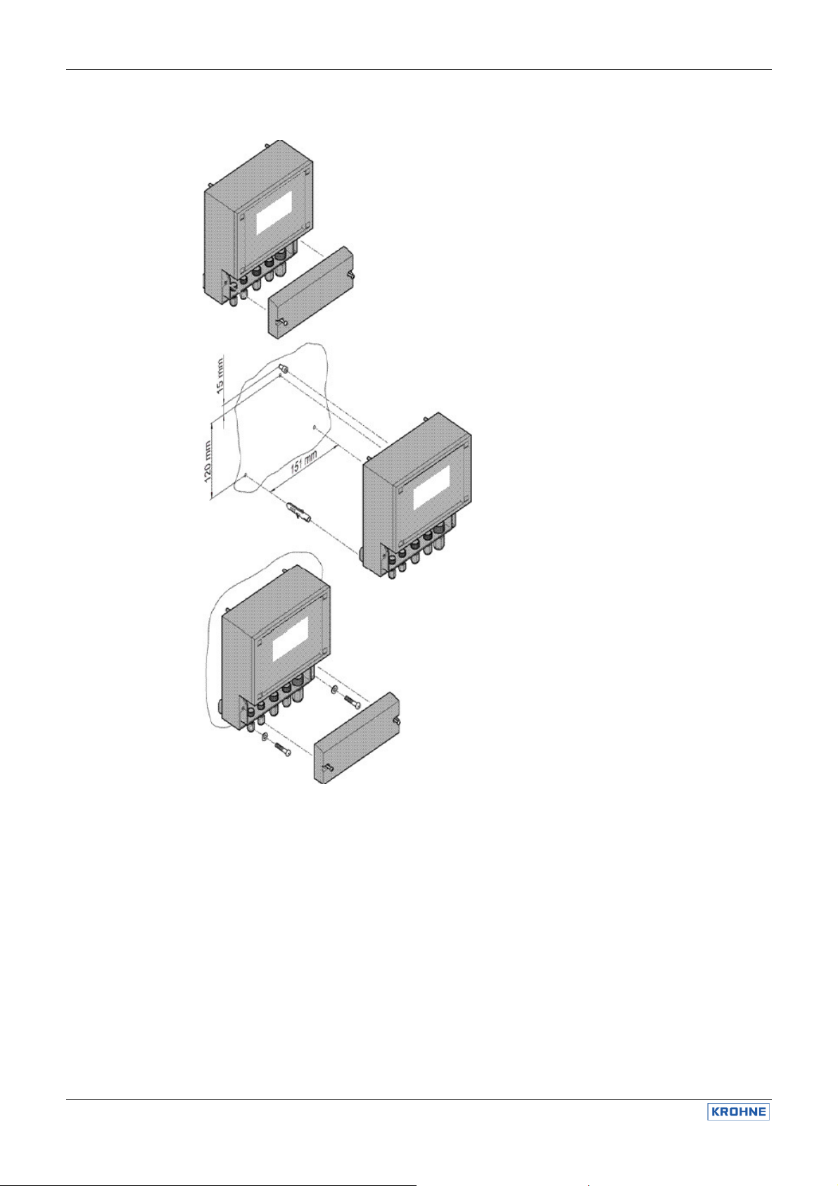
1.2 Installation of wall-mounting converters
Manual OPTISENS CAC 050 / IAC 050
Unscrew the terminal cover.
Drill three holes (max. M5) according to the drawing.
Mind that there are two ways for installation:
(1) You can hang the device upon the upper screw.
In that case drill the upper hole 120mm / 4.7” above
the lower two.
(2) Or you can slip the fixture on the back of the
device under the upper screw. In that case the upper
hole has to be another 15mm / 0.6” higher.
Insert the upper screw and make sure to leave at
least 3 mm between wall and screw head for the
fixture.
Mount the device and fix it with the two lower
screws. Close the terminal cover or start with the
connections.
7 OPTISENS CAC 050 / IAC 050
Page 8
2. Electrical connection
ATTENTION
You will find a detailed connection diagram on the following pages.
Before connecting the power supply check the information on the nameplate of the device!
Input, output and control lines must be installed separate from each other and separate from power lines!
For inputs and outputs use screened lines and connect the screen on one side only.
The conductivity measurement is interference-sensitive. Use a special screened cable and over long
distances or in humid atmosphere additionally an impedance converter.
For the connection of the temperature sensor use a low-resistance cable with a large diameter.
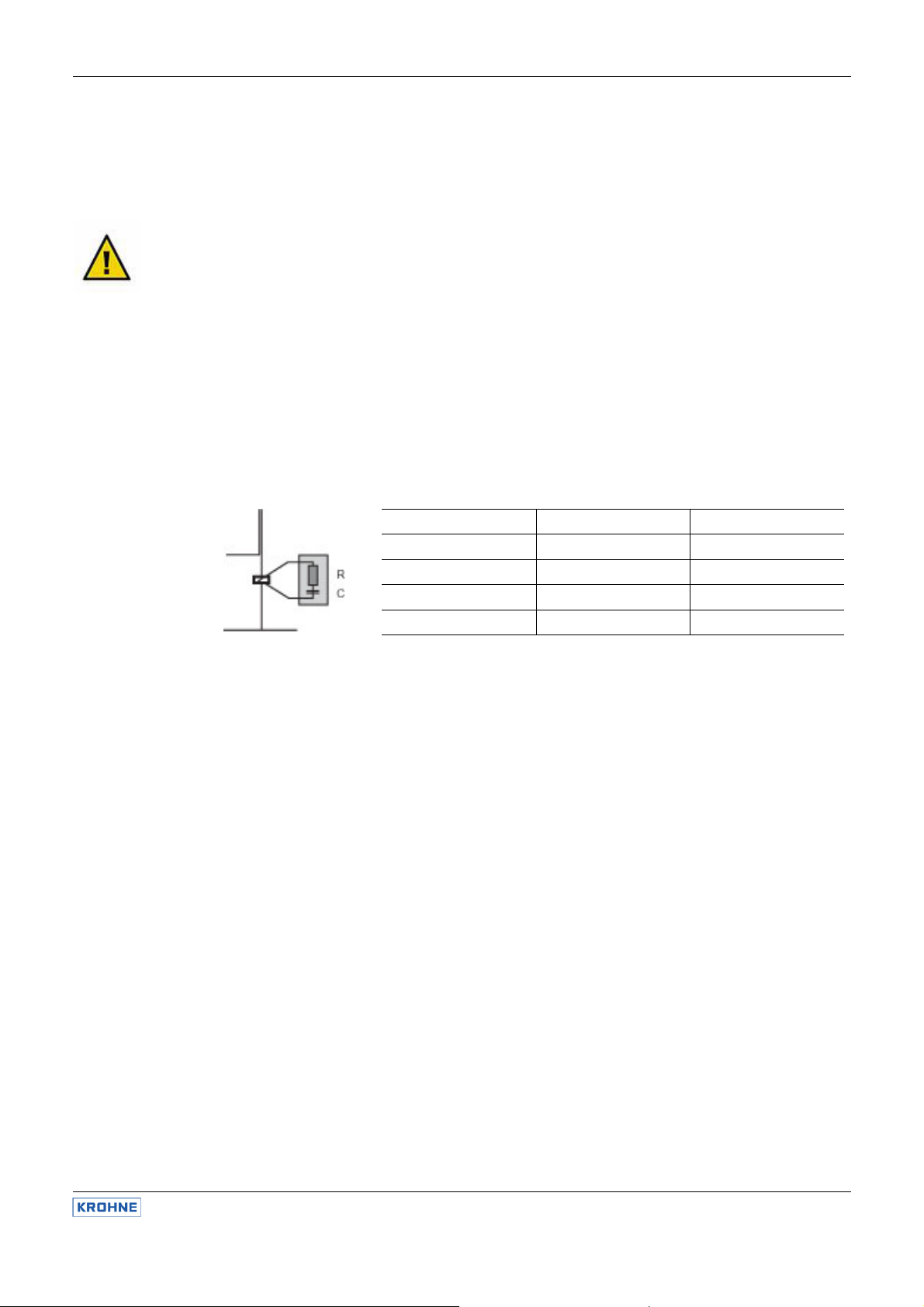
When using the relays, mind that with inductive loads, interference must be suppressed. If that is not
possible, the relay must be protected at the terminal block in the converter by a resistance-capacitance filter
or, in case of direct current, by a free- wheeling diode.
Manual OPTISENS CAC 050 / IAC 050
Current up to Capacitor C Resistance R
60 mA 10 nF 260 V 390 Ohm 2 Watt
70 mA 47 nF 260 V 22 Ohm 2 Watt
150 mA 100 nF 260 V 47 Ohm 2 Watt
1.0 A 220 nF 260 V 47 Ohm 2 Watt
OPTISENS CAC 050 / IAC 050 8
Page 9
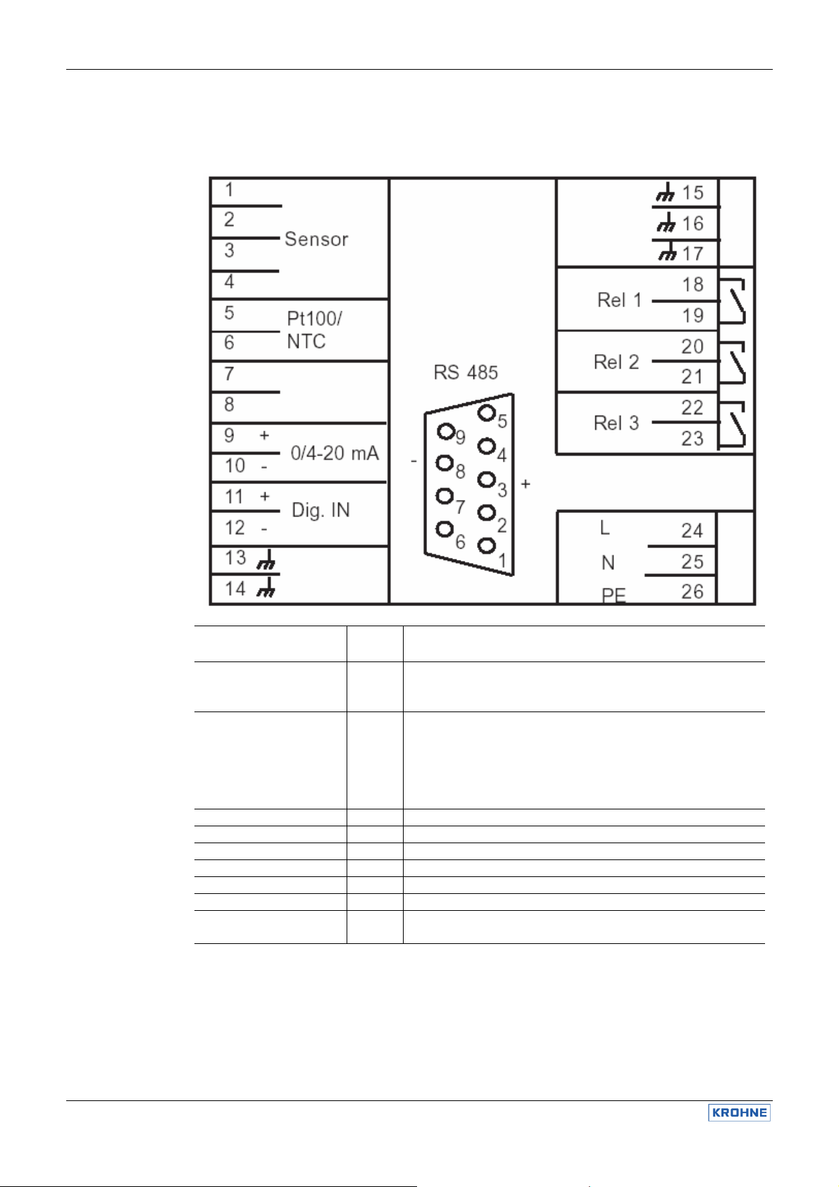
2.1 Connection diagram panel-mounting converter
Manual OPTISENS CAC 050 / IAC 050
NOTE
Connection
Conductivity sensor
conductive (CAC)
Conductivity sensor
inductive (IAC)
Pt 100 (CAC) / NTC (IAC) 5 + 6
Analog output 11 + 12 9 = + , 10 = - , max. burden 500 Ohm
Relay 1 18 + 19
Relay 2 20 + 21
Relay 3 22 + 23 Alarm relay
Power supply 24 – 26 check information given on name plate
RS485 (option) Sub-D 3 = +, 8 = -
When using different sensors or cables refer to the instructions for connection and cable color specifications
given there.
Termin
als
2 + 3
5 + 6
1 – 4
5 + 6
Notes
2 = Inner electrode = white
3 = Outer electrode = brown
Integrated Pt 100 = yellow & green
Measurement = cable #3
1 = screen, 2 = core cable #3
Voltage supply = cable #1
3 = screen, 4 = core cable #1
Integrated NTC = cable #2
5 = screen, 6 = core cable #2
4/7 bridged activates terminating resistance
9 OPTISENS CAC 050 / IAC 050
Page 10

2.2 Connection diagram wall-mounting enclosure
Manual OPTISENS CAC 050 / IAC 050
NOTE
Connection
Conductivity sensor
conductive (CAC)
Conductivity sensor
inductive (IAC)
PT 100 (CAC) / NTC (IAC) 4 + 5
Display contrast Display Potentiometer to adjust brightness
Analog output 11 + 12 11 = + , 12 = - , max. load 500 ohm
Relay 1 14 + 15
Relay 2 16 + 17
Relay 3 18 + 19 Alarm Relais
Power supply 20 - 22 Check information given on name plate
RS 485 (option) 23 + 24 23 = + , 24 = - , Jumper A activates terminating resistance
Digital input 26 + 27 26 = + , 27 = - , external controller stop and / or low water indication
When using different sensors or cables refer to the instructions for connection and cable color specifications
given there.
Termin
als
1 – 2
4 + 5
1 - 4 Measurement = cable #3
Notes
1 = Inner electrode = white
2 = Outer electrode = brown
Integrated Pt 100 = green & yellow
1 = core, 2 = screen cable #3
Voltage supply = cable #1
Integrated NTC = cable #2
4 = screen, 5 = core cable #2
OPTISENS CAC 050 / IAC 050 10
Page 11
3. Operation of the device
3.1 How to adjust parameters
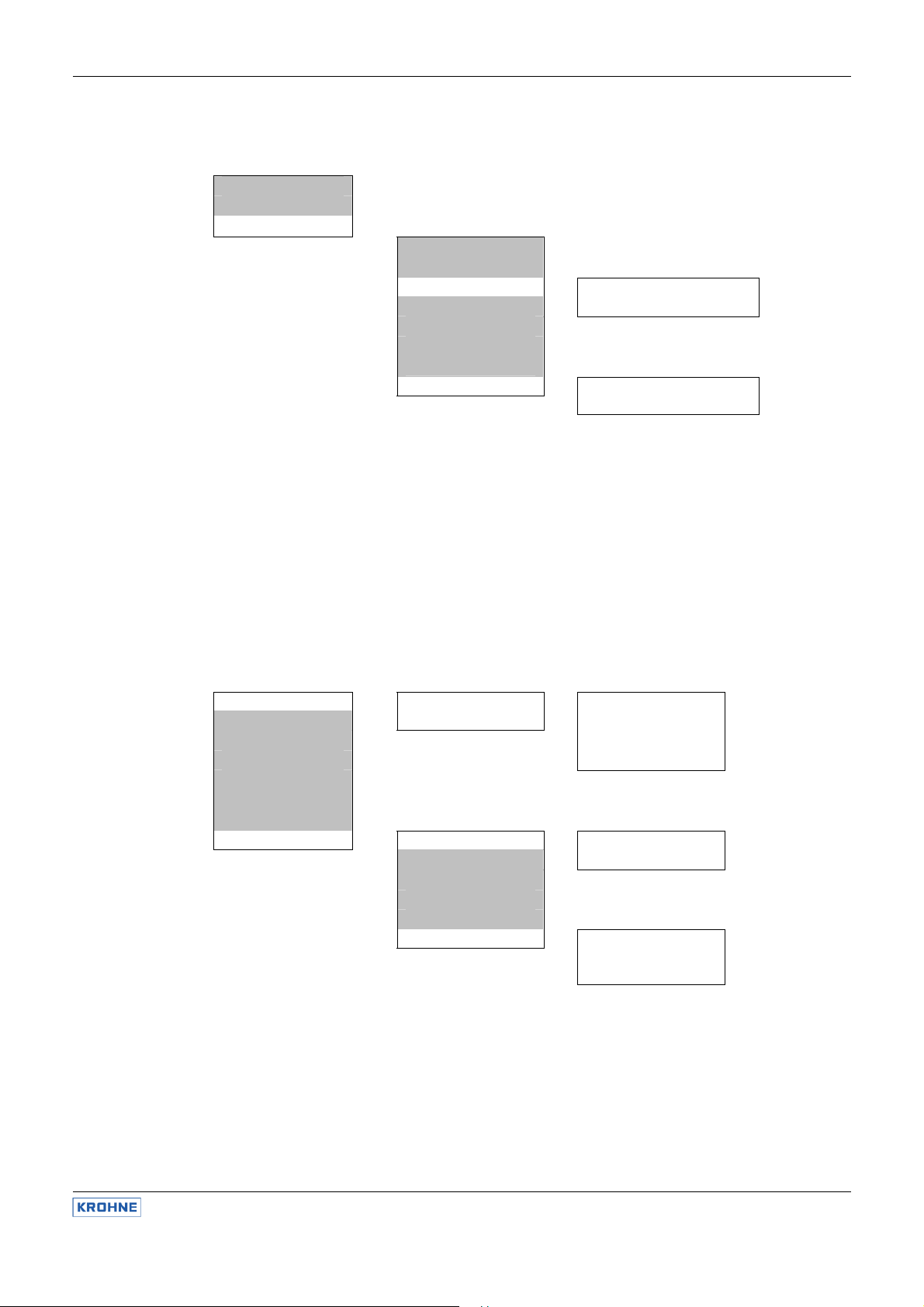
3.1.1 Selection between alternatives
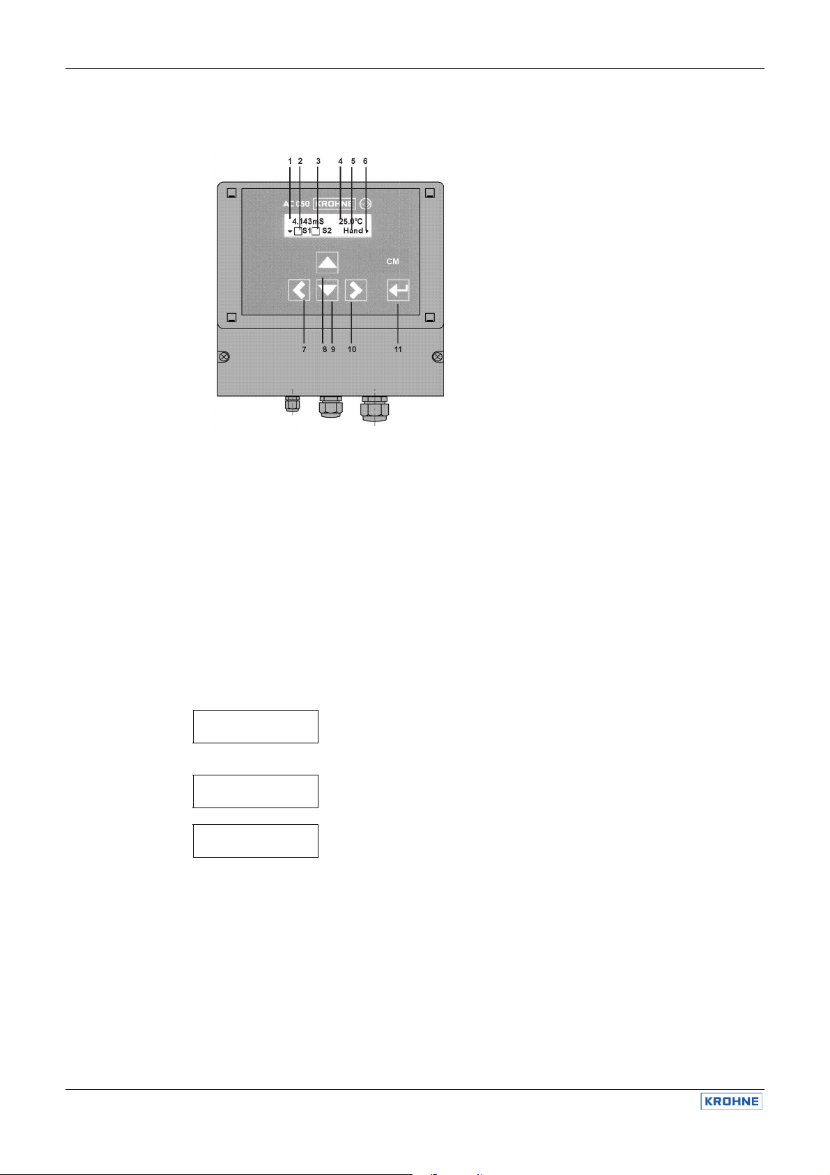
When turned on the device shows the measured values of conductivity and temperature together with the
controller mode (Man) and the status of the relays S1 and S2 (both OFF).
With five membrane keys you can move within the menu:
• With key you enter the main menu.
• With keys and you move up and down in the menu.
• With key you address a menu or parameter.
• With key you leave a menu without storing
• With key “Enter“ changes are stored.
For your convenience triangles in the display indicate the directions you can take from your position in the
menu.
Temp. comp.
Manual.
Temp. comp.
Auto
Temp. comp.
Manual.
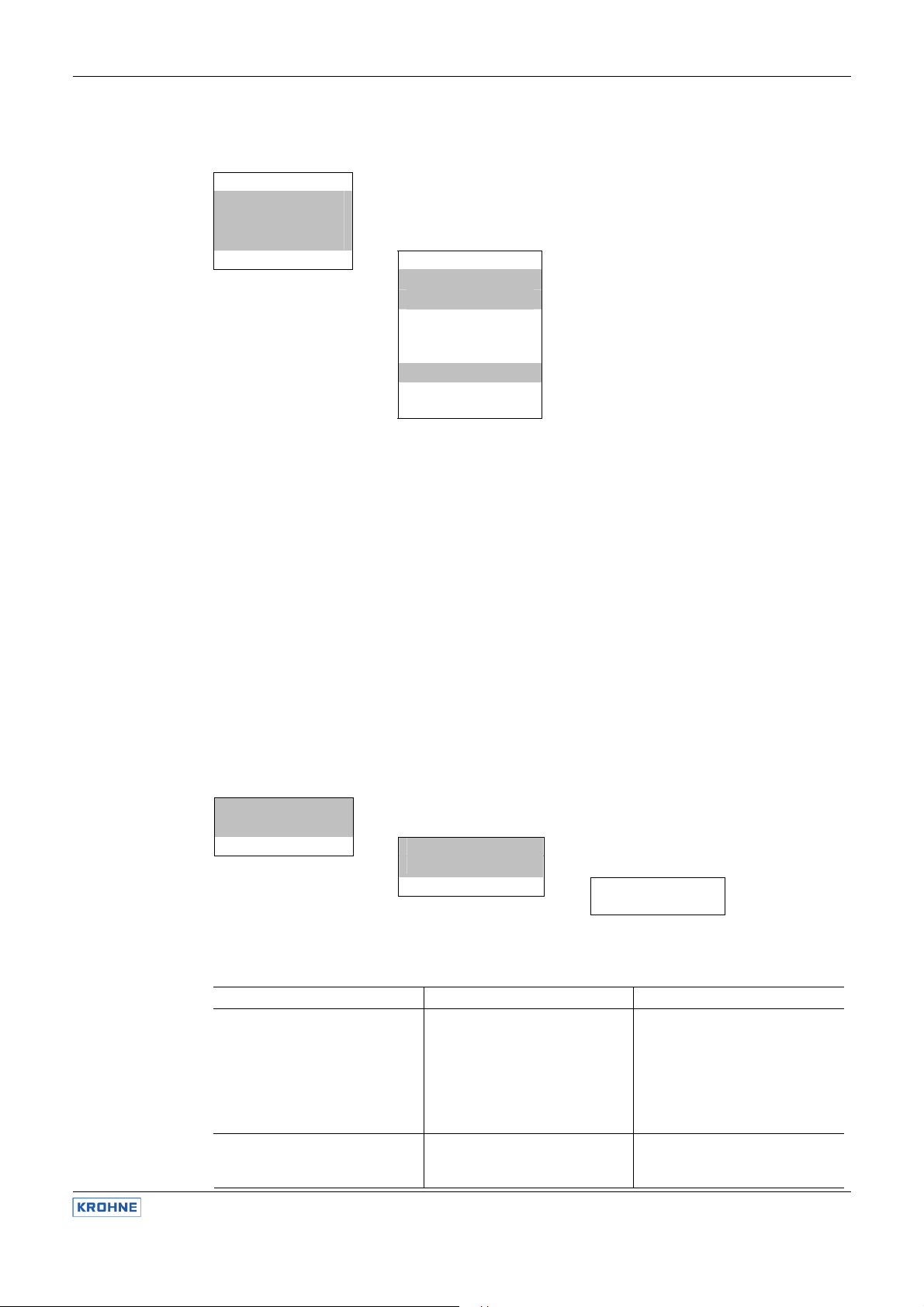
For many parameters you have the choice between two or more alternatives, for e. g. between manual and
automatic temperature compensation. For these parameters you need only key. Switch from one
alternative to the next until you either come back to where you started or until you reach the alternative you
were looking for.
With these parameters any changes are immediately valid - there is no need to store the change.
Manual OPTISENS CAC 050 / IAC 050
1 Measured value
2 Status relay 1
3 Status relay 2
relay OFF
relay ON
4 Temperature
5 Controller
AUTO: controller ON
MAN : controller OFF (manual operation
of the relays)
6 Orientation aids
7 Key left ()
8 Key up ()
9 Key down ()
10 Key right ()
11 Key “Enter“
1) When you address a parameter the actual setting is displayed.
2) Switch to the next alternative setting with key.
3) When you have come to the last alternative, pressing the key once
more will bring you back to the start.
11 OPTISENS CAC 050 / IAC 050
Page 12

3.1.2 Adjustment of numerical parameters
Enter password
058
Enter password
058
Enter password
062
3.2 Menu Overview
3.2.1 Main menu and basic settings
Numerical parameters can only be altered when a double arrow is visible behind the number. This double
arrow appears when you address the parameter with key.
Adjust the parameter with keys and . A short pressure on the key changes the last decimal by 1. If you
keep the key pressed, the value will continue changing until the pressure is released.
Store the changes with key „Enter“. The double arrow disappears.
6.98 mS 25.0°C
S1 S2 Auto
Main menu
Temp. comp. Temperature compensation
Enter password Password function
Set points Controller settings - set points, P ranges, I functions
Limit values Alarm function
Basic settings
Service Contr. settings
Turn-on delay
Analog output
Language
Temp. coeff.
Cell factor
Cable Comp.
Bus address
Meas. range
Averaging
The parameters are sorted into two menus: In the main menu you will find all functions which are used
regularly. The menu basic settings contain all parameters which are set just once during start-up.
On the following pages you will find information on how to adjust parameters and which parameters you
need for which application. The information follows the following scheme:
1) General adjustments: password and language
2) Adjustments for measurement: cable compensation and temperature compensation, averaging and
adjustment of the cell factor
3) Adjustments of the controller: selection of the controller version and corresponding parameters
4) Adjustments to read out data: analog, digitally and/or as alarm
Manual OPTISENS CAC 050 / IAC 050
1) Address the parameter with key .
2) A double triangle appears behind the number indicating that the
number can be changed now with keys and .
3) Store the new value with key „Enter“. The double arrow disappears the new value is stored.
Display of the measured values
Press key to enter the main menu.
Basic settings
Cal. Pt 100 / NTC
All parameters which are set just once
at the beginning can be found in the
menu “basic settings“
OPTISENS CAC 050 / IAC 050 12
Page 13

3.3 Password and language
3.3.1 Enter password
3.3.2 Language
Main menu
.
.
Enter password
056 Code
To get access to the various parameters you have to enter the correct password:
• Code 11 gives access to the parameters „calibration“, „temperature compensation“, and „set points“.
• Code 86 gives access to all parameters and functions.
With any other number it is impossible to select, view or change any parameter.
Main menu
.
.
Basic settings
Language
For the communication with the device you can choose from a variety of languages.
Since choosing a language is part of the basic settings, it requires code 86. If a different code is set, you will
be asked to enter the correct password.
Manual OPTISENS CAC 050 / IAC 050
Enter password
Basic settings
.
.
Language
We speak
English
13 OPTISENS CAC 050 / IAC 050
Page 14
4. Adjustments for the measurement
4.1 Configuration of the converter
OPTISENS CAC 050 / IAC 050 14
Main menu
Temp. comp.
.
.
.
Basic settings
Temp. coeff. Adjustment of the deviation per °C
Cell factor c Adjustment of the cell factor (sensor charact.)
Cable comp. Zero point correction (cable capacitance)
Meas. range Selection of the measuring range
Averaging Activation of a smoothing function
The conductivity measurement is influenced by temperature. This influence is compensated automatically or
manually. For manual compensation the temperature is entered manually, for automatic compensation a
temperature sensor must be connected. Compensation is carried out linearly using a temperature coefficient
in %/K which depends upon the composition of the test water.
The capacitance of the sensor cable can lead to a slight deviation of the measurement. This deviation can be
eliminated by cable compensation.
Especially in the lower measuring ranges the measurement tends to get a bit unsteady due to the high
resistance of the water. The signal can be smoothed out by activating an averaging function.
Conductivity sensors are optimized for certain measuring ranges by their geometric dimensions. These
define the cell factor (c value). If you want to use a sensor with a different cell factor or if you want to
calibrate the measurement, adjust the cell factor accordingly.
All these adjustments are part of the basic settings, since they are carried out only once at the beginning.
Main menu
.
.
Basic settings
Configuration
Temp. sensor
The devices CAC 050 and IAC 050 2 analog inputs:
Input 1 is for conductivity measurements (conductive with CAC 050, inductive with IAC 050) for a variety of
measuring ranges:
Method Measuring range Sensor
conductive 0.00...20.00 MOhm/cm c = 0.05/cm with Pt100
0.000...2.000 µS/cm c = 0.05/cm with Pt100
0.00...20.00 µS/cm c = 0.05/cm with Pt100
0.0...200.0 µS/cm c = 0.05/cm with Pt100
0.000…2.000 mS/cm c = 0.2/cm with Pt100
0.00...20.00 mS/cm c = 1/cm with Pt100
0.0...200.0 mS/cm c = 10/cm with Pt100
0.00...20.00 mS/cm Sensor with NTC
0.0...200.0 mS/cm Sensor with NTC
0...2000 mS/cm Sensor with NTC
Manual OPTISENS CAC 050 / IAC 050
Selection between automatic and manual temperature compensation,
adjustment of temperature for manual compensation.
Basic settings
Cal. temp. Calibration of the temperature measurement.
.
.
.
Basic settings
.
.
Configuration
Measurement
Page 15

NOTE
4.2 c value (cell factor)
4.2.1 Calibration via cell factor
NOTE
Input 2 is for temperature measurements.
At works the CAC 050 is configured for the measuring range 0.000…2.000 mS/cm.
The IAC 050 is configured for the measuring range 0.0…200.0 mS/cm.
With code 99 you can change the configuration. If you have entered code 99, a new menu appears at the
end of the list of basic settings called “configuration“.
Displayed is always the actual active configuration. With key you can switch from one alternative to the
next, i. e. for measurement from one measuring range to the next and for temperature from Pt100 to NTC.
Press the key again until you reach the desired configuration or return to the original setting.
A variety of conductive sensors is available with optimized design for certain measuring ranges, expressed in
the c value. Whenever you select a measuring range in the menu “configuration“, the converter automatically
selects the appropriate c value. In the basic settings use the menu “cell factor c“ to check, change or adjust
the c value according to your sensor.
Main menu
.
.
Basic settings
Cell factor c
Please make sure that the cell factor of the sensor is appropriate for the selected measuring range. In
contrast to the device which can be used for all ranges, the sensor’s applicability is limited by its geometrical
design, i. e. the size and arrangement of its electrodes. The cell factor is the numerical expression of this
design. With this cell factor the device can process the measurement and calculate standardized conductivity
values.
The cell factor is a sensor characteristic. You will find it indicated on the sensor. Prior to measurement, check
that the cell factor stored in the device corresponds to the sensor used.
The cell factor of a sensor can change slightly due to pollution or aggressive cleaning. It might even be
influenced by the armature. These deviations can be eliminated by determining the conductivity with a
comparative method and adjusting the cell factor until the measured value displayed by the device equals
this conductivity.
This calibration is only as good as the comparative method! Since it requires sophisticated equipment and
some skills, we advise to do it only if the highest precision is required. Usually the errors caused by
temperature measurement or inappropriate temperature coefficients are much higher than the deviations of
the cell factor.
Manual OPTISENS CAC 050 / IAC 050
Cell factor c
Cell factor c
0.050
Basic settings
.
.
15 OPTISENS CAC 050 / IAC 050
Page 16
4.3 Cable compensation and averaging
4.3.1 Cable compensation (zero point correction)
4.3.2 Averaging
4.4 Temperature compensation
Main menu
.
.
Basic settings
Cable comp.
Averaging
The cable connecting the sensor to the device can cause a capacitive error. To detect and eliminate this
error, connect the sensor to the device and let the dry sensor hang free in the air. If the measured value
displayed is not zero, then compensate by pressing keys and. Now the value displayed is zero.
Especially in the lower ranges the signal might become a bit unstable, due to the very high resistance of the
solution. In that case you can smooth out the signal by averaging over subsequent measurements. When the
averaging function is activated, the average is displayed instead of the single measured values.
Main menu
Temp. comp.
.
.
.
.
.
Auto comp. Manual comp.
Temperature
25.0°C
Basic settings
Temp. coeff.
Select between two ways of compensation:
1) Automatic compensation with temperature sensor
Mind that the temperature sensor should always measure the temperature around the conductivity sensor.
When conductivity sensor and temperature sensor are not immersed in the same solution, better switch to
manual compensation.
2) Manual compensation
If the temperature can be regarded as constant, you can enter the temperature manually instead of
measuring it continuously. The device will then compensate the temperature error of this temperature.
Basic settings
.
.
.
.
.
.
Automatic
compensation
Temp. comp.
Basic settings
Cal. temp.
.
.
.
.
Manual OPTISENS CAC 050 / IAC 050
Cable compensation
0.00 mS
press& simultaneously
Averaging
Averaging
ON
Manual
compensation
Temp. comp.
Calibration
temperature
Cal. temp.
0.0°C
Temperature
coefficient
Temp. coeff.
2.5%/K
OPTISENS CAC 050 / IAC 050 16
Page 17

4.4.1 Calibration of the temperature measurement
4.4.2 Temperature coefficient
When using a 2-wire connection for the temperature sensor, please check the temperature measurement in
the beginning. If the displayed temperature differs from the real temperature, enter the deviation as
correction in the basic settings. This correction will be added to all temperature measurements. If your
calibration was correct, the temperature displayed is now equal to the real temperature.
The temperature influence on the conductivity depends upon the composition of the solution and often
cannot be expressed by a simple equation. Instead the temperature dependency is compensated using a
linear coefficient given as deviation in % per K.
For most applications a coefficient of 2.5%/K can be used to good results. For ultra-pure water better select
the non-linear compensation “pure water“.
5. Adjustments of the controller
Main menu
.
.
Set points
.
.
Basic settings
Contr. settings
Turn-on delay
For any type of controller you have to enter one or two set points, and you have to tell the device whether
these set points are reached by increasing or decreasing the measured value.
You can choose between three different controller versions:
ON/OFF controller
The ON/OFF controller switches ON if the measured value exceeds the set point and OFF if it drops back
below it or vice versa. Dosage is always carried out with 100% (ON) or 0% (OFF). The parameter for an
ON/OFF controller is the hysteresis.
P controller
The P controller or proportional controller reduces the dosage in the vicinity of the set point proportional to
the control deviation. This is easily achieved if the analog output is used as steady control output. If the
relays are used, the proportional reduction is achieved by either reducing the switch frequency (Impulsefrequency controller) or reducing the time within a given period of time in which the relay is ON (pulse-pause
controller). The parameters for a P controller are the P range and the impulse- frequency or the pulse+
pause time and the minimum pulse. (See Point 5.3)
PI controller
The PI controller is a P controller with an additional I function. Adjustments and parameters are the same as
for a P controller. Additionally the integral action time has to be adjusted which determines the I function.
The I function eliminates the P controller’s disadvantage of a remaining steady-state deviation.
Manual OPTISENS CAC 050 / IAC 050
Selection of ON/OFF, P or PI controller, adjustment of P ranges and I
functions for 2 set points.
Basic settings
.
.
Adjustment of frequencies and pulse/pause
times, hysteresis, direction of the control
action, delay
17 OPTISENS CAC 050 / IAC 050
Page 18

5.1 ON/OFF controller
5.2 P / PI controller as impulse-frequency controller
Main menu
.
.
Set points
.
.
.
1,50 mS controller versions for S1
0,00 mS
Integral time S1
Set point S2
0,50 mS Controller Settings
P range S2
0,00 mS .
Integral time S2 Direction S1
000 sec. Raise
Direction S2
Basic settings
Contr. settings
For an ON/OFF controller you have to set the following parameters:
1) Set points S1 and S2
Set point S1 refers to relay 1, set point S2 refers to relay 2.
2) P range and integral action time for S1 and S2
For an ON/OFF controller set P range = 0 and integral time = 0.
3) Acting direction for S1 and S2
Select “raise“ if the dosage raises the measured value.
Select “lower“ if the dosage lowers the measured value.
4) Optionally a hysteresis
The hysteresis prevents fast switching in the vicinity of the set point. If hysteresis is activated (by setting a
value > 0) the relay switches only when the set point is exceeded by half the hysteresis.
Main menu
.
.
Set points
.
.
.
controller version
1,50 mS Controller versions for S1
P range S1 and S2
0,00 mS
Integral time S1
000 sec.
Basic settings
Contr. settings
Manual OPTISENS CAC 050 / IAC 050
Set point S1
You can choose different
P range S1 and S2
000 sec.
Basic settings
.
Set points and
.
Lower
Hysteresis
0,01 mS
Set point S1 You can choose different
Set point S2
0,50 mS
P range S2
0,00 mS
Integral time S2
000 sec
Basic settings
.
Controller settings
Pulse-Freq. S1
00*100 l/h
Pulse-Freq. S2
00*100 l/h
Direction S1
Raise
Direction S2
Lower
OPTISENS CAC 050 / IAC 050 18
Page 19

5.3 P / PI controller as pulse-pause controller
For an impulse-frequency controller you have to set the following parameters:
1) Set points S1 and S2
S1 refers to relay 1, S2 refers to relay 2.
2) P range and integral action time for S1 and S2
Adjust a P range > 0. For a P controller set integral time = 0, for a PI controller set an integral time > 0.
3) The acting direction for S1 and S2
Select „raise“ if the dosage raises the measured value.
Select „lower“ if the dosage lowers the measured value.
4) Pulse-frequencies for S1 and S2
Enter the maximum pulse-frequency that corresponds to 100% dosage.
Main menu
.
.
Set points
.
.
.
Set points S2 Direction S1
0.50 mS Raise
P range S2
0.00 mS lower
Integral time S2 .
000 sec. .
Basic settings
Contr. settings
For a pulse-pause controller you have to set the following parameters:
1) Set points S1 and S2
S1 refers to relay 1, S2 refers to relay 2.
2) P range and integral action time
Adjust a P range > 0. For a P controller set integral time = 0, for a PI controller set an integral time > 0.
3) Pulse-frequencies for S1 and S2
Both frequencies must be set to 00, otherwise the controller will act as an impulse-frequency controller.
4) The acting direction for S1 and S2
Select „raise“ if the dosage raises the measured value.
Select „lower“ if the dosage lowers the measured value.
5) Pulse + pause time
Define a period of time during which the relay is proportionally to the control deviation ON (pulse) or OFF (pause),
respectively.
Manual OPTISENS CAC 050 / IAC 050
You can choose different
Set points and
controller version
Set point S1 and S2
1,50 mS Controller settings
P range S1 Pulse-Freq. S1
0.00 mS
Integral Time S1 Pulse-Freq. S2
000 sec. 00*100 l/h
Basic settings
.
00*100 l/h
Direction S2
Pulse+Pause
10 s
Least Pulse
0.1 s
controller versions for S1
The pulse+pause
time must be twice as
long as the least
pulse time
19 OPTISENS CAC 050 / IAC 050
Page 20

5.4 Activation and deactivation of the controller
The controller is activated and deactivated from the main display without any menus. Press key to switch
from Manual Mode (controller OFF) to Automatic Mode (controller ON) and vice versa. The actual mode is
indicated in the display.
Make sure that the controller is deactivated before connecting dosing pumps or other actuators!
CAUTION
5.5 Turn-on delay
5.6 External controller stop
NOTE
Main menu
.
.
Basic settings
Contr. settings
OFF
ON
Turn-on delay
180 s
Set a delay time which has to pass before the controller is activated after start-up or power interrupt. This
allows the measurement to settle and prevents inappropriate dosage of chemicals.
You can activate or deactivate the controller with an external switch by using the digital input. This feature
requires no settings or adjustments. If the digital input is short- circuited, the controller stops, and the
message „external controller stop“ appears in the display.
This feature can also be used as lack-of water indication. Just connect a level sensor to the digital input.
Manual OPTISENS CAC 050 / IAC 050
Basic settings
.
.
Turn-on delay
Turn-on delay
Turn-on delay
OPTISENS CAC 050 / IAC 050 20
Page 21
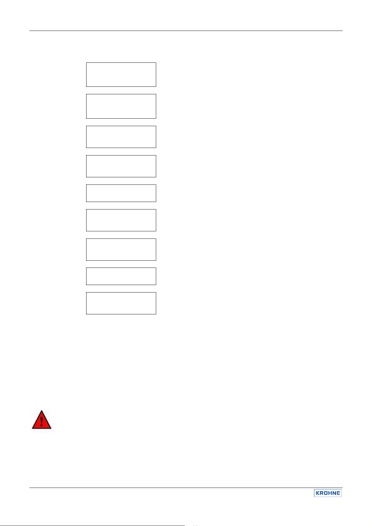
5.7 Manual operation of the relays
1.402 mS 25.0°C
S1 S2 Auto
1.402 mS 25.0°C
S1 S2 Man
1.402 mS 25.0°C
S1 S2 Man
1.402 mS 25.0°C
S1 S2 Man
1.402 mS 25.0°C
S1 S2 Man
1.402 mS 25.0°C
S1 S2 Man
1.402 mS 25.0°C
S1 S2 Man
1.402 mS 25.0°C
S1 S2 Man
1.402 mS 25.0°C
S1 S2 Man
For manual operation you need no menu.
• With key you switch OFF the controller.
• With key you switch between Manual operation <> operation mode S1 <> operation mode S2 <>
manual operation.
• In the operation mode you can switch ON and OFF the selected relay with key .
• A flashing square indicates that the relay is in operation mode.
• A dark square indicates that the relay is switched ON.
• A light square indicates that the relay is switched OFF.
If you switch ON a relay it stays ON until you switch it OFF again manually!
Manual OPTISENS CAC 050 / IAC 050
1) If the controller is ON, switch it OFF with key .
Instead of „Auto“ the display shows „Man“.
2) Switch to the operation mode of S1 with key.
The square to the left of S1 starts to flash.
3) Switch ON relay 1 with key .
The square to the left of S1 gets dark.
4) Switch OFF relay 1 again with key .
The square gets light.
5) Switch to the operation mode of S2 with key.
The square to the left of S2 starts to flash.
6) Switch ON relay 2 with key .
The square to the left of S2 gets dark.
7) Switch OFF relay 2 again with key .
The square gets light.
8) Leave the operation mode of relay 2 with key .
Both squares appear light, none flashes - You have left the operation
mode.
WARNING
21 OPTISENS CAC 050 / IAC 050
Page 22

5.8 Limit values
NOTE
5.8.1 Turn-on delay
5.9 Dosage check
NOTE
NOTE
Manual OPTISENS CAC 050 / IAC 050
Main menu
.
.
Limit values
2.00 mS
Limit S2
1.00 mS
Turn-on delay
005 sec.
For the alarm, you can adjust two limits:
• Limit 1 is an upper limit. If the measured value exceeds limit 1, an alarm is issued.
• Limit 2 is a lower limit. The alarm is issued if the measured value drops below limit 2.
In case of alarm the display shows the message „limit 1“ (or 2, respectively) and relay 3 is switched ON. This
relay can be used to activate an external horn or lamp.
The limit function is active only if the controller is set on automatic mode. When you switch the controller to
MAN, the alarm is extinguished.
In some applications it happens regularly that the measured value exceeds a limit for a short period of time.
To avoid having an alarm issued under these circumstances you can adjust a turn-on delay which has to
pass before an alarm is issued. If the turn- on delay time is >0 then the alarm is issued only if the cause of
alarm remains longer than the specified turn-on delay time.
Main menu
.
.
Basic settings
Contr. settings
Dosage check S2
00 min
In the basic settings of the controller you can define, how long a controller is supposed to dose with 100%
without raising alarm.
If the controller output is 100% for more than the specified time, this is interpreted as an indication of failure,
and the device issues an alarm and deactivates the controller, thus stopping further dosage.
The dosage check is a safety catch to prevent hazardous chemicals to be set free in case of a defective
dosing tube or tube connection.
In case of an alarm due to dosage check, only the controller concerned is deactivated.
If you set the dosage check time to 0 minutes, the dosage check function is deactivated.
Limit values
Limit S1
Basic settings
.
.
Controller settings
Dosage check S1
00 min
OPTISENS CAC 050 / IAC 050 22
Page 23

6. Alarm
Manual OPTISENS CAC 050 / IAC 050
Additional to the limit function the device provides various check functions that raise alarm.
In case of an alarm, relay 3 switches, undelayed, and the cause of the alarm is indicated in the display.
If the cause of alarm is such that control is no longer possible or might even be dangerous, the controller is
automatically deactivated until the alarm is switched off.
Switching off the alarm is done automatically by the device as soon as the cause of alarm is eliminated.
Sensor check during measurement
During measurement all connected sensors are checked. If an analog input does not receive a correct signal,
for e. g. if a cable is broken or a sensor damaged, an alarm is issued, and the controller deactivated. Alarm
and controller stop remain until the analog input receives correct signals again.
Dosage control
If a controller output is 100% longer than the defined dosage time, an alarm is issued, and the corresponding
controller is deactivated. The alarm remains until the controller output drops below 100% - it can also be
extinguished by setting the controller to manual mode.
Cause of alarm only active in AUTO mode deactivates controller
Error input 1 no yes
Error input 2 no yes
Limit yes no
Dosage yes yes
23 OPTISENS CAC 050 / IAC 050
Page 24

6.1 Error messages
7. Output
Manual OPTISENS CAC 050 / IAC 050
Error message Cause Action
Error input 1 The conductivity sensor gives no
signal.
Error input 2 The temperature sensor gives no
signal.
Please check the connections, the cable
and the sensor for signs of damage.
Please check the connections, the cable
and the sensor for signs of damage. This
message also appears if automatic
temperature compensation was selected
although no temperature sensor was
used.
Limit 1 / 2 The measured value exceeded limit
1 (or dropped below limit 2,
Please check the dosing and readjust the
control parameters, if necessary.
respectively).
Dosage Pump 1 (or 2, resp.) feeds with
100% for more than the defined
period of time.
Ext. controller stop The digital input has been short-
circuited.
Please check the dosing, especially the
feeding tubes and connections. Caution!
Carefully check for leaking chemicals!
This only indicates the external controller
stop. If, however, you have connected a
level sensor, this message appears due
to the „lack of water“ alarm.
Main menu
.
.
Basic settings
Analog output
Basic settings
.
.
.
0 – 20 mA 4-20 mA
.
.
0.00mS Corresp. to 4 mA
Analog output
Select output -between 0-20 mA and
Selection
Begin 0/4 mA -of the measured value
End 20 mA -of the measured value
2.00 mS Corresp. to 20 mA
Analog output -between readout of the
Measuring value Measurement or the
Control values
Serial interface
RS485 (option)
Bus address
Nr. 00
Bus address
Set a number between
0 and 31 to address the
device via data bus.
OPTISENS CAC 050 / IAC 050 24
Page 25

7.1 Current output
7.2 Serial interface RS485 (option)
You can read out the measured value as 0/4…20 mA signals via the current output.
With the setting 4…20 mA the resolution is lower, but defective cable connections are immediately evident.
With the parameters Begin and End you define which part of the measuring range you want to read out.
Alternatively you can use the current output as steady-state controller output. In that case assign the current
output to controller S1 or S2, respectively.
The devices are available with serial interface RS485 by means of which they can be integrated in a data
bus system. Via the interface, all settings, measured and control values as well as any error messages can
be read out digitally.
Devices with RS485 are automatically delivered with the leaflet „Information on the RS485“ which contains
instructions on the communication and a complete list of the functions available via interface.
8. Operation and maintenance
8.1 Maintenance of the device
8.2 Display contrast
8.3 Exchange fuse
The device does not require any maintenance. There is no need for readjustment. If you want to have the
device checked regularly, you are welcome to send it to KROHNE Water Solutions. Alternatively the device
can be checked on site by one of our engineers.
With devices in wall-mounting enclosures the display contrast can be adjusted to the actual light conditions
by means of a potentiometer. It is indicated in the connection diagram with the word „display“.
Devices in wall-mounting enclosures have an internal fuse which has to be replaced at need. You will find a
spare fuse fixed to the inside of the terminal cover. Information on the fuse can be found in the chapter
„Technical data“.
To exchange the fuse, open the front carefully. The fuse is located on the right hand side. It is kept in place
by a Bayonet lock. Turn the lock to the left until the fuse pops up. Exchange it and fix the new fuse by turning
the lock to the right. Put the front back on and fix it tightly.
Disconnect the power supply before opening the device!
Manual OPTISENS CAC 050 / IAC 050
WARNING
Mind that the cable connections to the front are not damaged, broken or torn during the process!
ATTENTION
8.4 Cleaning
25 OPTISENS CAC 050 / IAC 050
The front and the display should not get in touch with organic solutions such as methanol. Never let water
get inside the device. We suggest to simply use a damp cloth for cleaning.
Page 26

8.5 Maintenance of the conductivity measurement
8.6 Disposal
8.7 Service
8.7.1 Product info
8.7.2 Analog inputs
8.7.3 Erase settings (reset)
The metallic surfaces of the sensors must be cleaned regularly. Slight changes of the sensor due to usage,
aggressive cleaning or even installation conditions can be corrected by means of adjustment of the c value in
the basic settings.
For disposal please notice that the device contains electrolyte capacitors which have to be disposed
separately.
Main menu
.
.
.
.
.
Service
Analog inputs
Input 1 003
Input 2 25.0°C
Erase settings
Press &
In this menu you will find information which is especially important for any inquiries, updates or problems.
These figures allow a precise identification of the device (hardware and software).
Here you can see the raw data the device obtains from the sensors. They are not influenced by
compensations or calibration and offer valuable information in case of problems with the measurement or the
device.
If you have problems interpreting this data, send them to your supplier together with the device data and ask
for support.
With this function you can erase all customer settings and restore the original at-works data.
The process takes some 30 seconds. When it is finished the display will show the measured value, and the
controller will switch off.
Unit no.
No. 041
Software date
M/Y 1.00
Service
Product info
Manual OPTISENS CAC 050 / IAC 050
Product. date
M/Y 1.00
Analog inputs
Analog inputs
Erase settings
simultaneously
OPTISENS CAC 050 / IAC 050 26
Page 27

9. Technical data
9.1 Technical data
Manual OPTISENS CAC 050 / IAC 050
Feature
Version panel-type converter wall-mounting enclosure
Dimensions (w x h x d) 96 x 96 x 127 mm / 3.8 x 3.8 x 5” 165 x 160 x 80 mm / 6.5 x 6.3 x 3.1”
Weight 0.8 kg / 1.8 lbs 1.0 kg / 2.2 lbs
Terminals screw terminals max. 1.5 mm2 Spring terminals max. 1,5 mm2
Protection class IP 54 (front), IP 55 (front door) IP 65
Power supply 230 V +6/-10 %, 50/60 Hz, optional 110 V or 24 V
Internal fuse none 230 V: 63 mA slow
Power consumption 10 VA
Display LCD, 2-line, 2x16 characters, illuminated background
Current output 0/4...20 mA, galvanically isolated, max. loading 500 Ohm
Interface (option) RS485, Baud rate 9600, data format 8Bit, 1 Start and 1 Stop bit
Controller ON/OFF controller with hysteresis, P or PI controller as Pulse- Pause- or
Set points 2 set points adjustable within the measuring range
Alarm function with min. and max. limit and turn-on delay
Contact rating 6 A/ 250 V, max. 550 VA resistive load (with RC protective circuit)
Operation temperature 0…+50°C / 32…+120°F
Storage temperature -20…+65°C / -5…+150°F
Humidity max. 90% at 40°C /105°F non-condensing
CAC 050 R
IAC 050 W
measured value and temperature with dimensions indication of relay
status
Impulse-frequency controller, steady controller, bidirectional PI control
action, adjustable onset-delay, dosage control function, manual operation
of the relays, controller stop via external switch or level sensor (lack-ofwater sensor)
CAC 050 W
IAC 050 W
110 V: 125 mA slow
24 V: 800 mA semi-slow
27 OPTISENS CAC 050 / IAC 050
Page 28

9.2 Dimensions
9.2.1 Panel-mounting enclosure
Manual OPTISENS CAC 050 / IAC 050
9.2.2 Wall-mounting enclosure
OPTISENS CAC 050 / IAC 050 28
Page 29

Manual OPTISENS CAC 050 / IAC 050
10. Device return form
This device has been carefully manufactured and
tested. If installed and operated in accordance with
these operating instructions, it will rarely present any
problems. Should you nevertheless need to return a
device for inspection or repair, please pay strict
attention to the following points:
Due to statutory regulations on environmental
protection and safeguarding the health and safety of
our personnel, KROHNE Water Solutions may only
handle, test and repair returned devices that have
been in contact with products without risk to personnel
and environment.
This means that KROHNE Water Solutions can only
service this device if it is accompanied by the
following certificate confirming that the device is safe
to handle.
If the device has been operated with toxic, caustic,
flammable or water-endangering products, you are
kindly requested:
• to check and ensure, if necessary by rinsing or
neutralizing, that all cavities are free from such
dangerous substances,
• to enclose a certificate with the device confirming
that is safe to handle and stating the product
used.
We cannot service this device unless accompanied by
such a form.
S P E C I M E N certificate
Email:…………………………………………………...
The enclosed device
Type:……………………………………………………………………………………………………………………………
KROHNE Water Solutions Order No. or Series No.:……………………………………………………………………..
has been operated with the following liquid:……………………………………………………………………………….
Company:………………………………………………. Address:…………………………………………………
Department:…………………………………………… Name:……………………………………………………
Tel. No.:……………………………………………….. Fax No.:……………………………………………........
Because this liquid is
water-hazardous toxic caustic.. flammable
we have
checked that all cavities in the device are free from such substances
flushed out and neutralized all cavities in the device
We confirm that there is no risk to humans or environment through any residual liquid contained in this device.
29 OPTISENS CAC 050 / IAC 050
Page 30

11. Customer settings - for reference
OPTISENS CAC 050 / IAC 050 30
Device
Type: ………………. date of installation: ……………….
Serial number: ………………. Software version: ……………….
Measurement
c value: ………………... Averaging
Temperature compensation
Temperature: …………….°C Correction: …………….°C
Temperature
Analog output
Output
for conductivity
Controller S1 Controller S2
Start: ……………………
End: ……………………
Controller
Controller S1 Controller S2
Acting direction Acting direction
raise lower raise lower
Set point: …………………… Set point: ……………………
Hysteresis: …………………… Hysteresis: ……………………
P range: …………………… P range: ……………………
Integral time: …………………..s Integral time: …………………..s
Pulse+ pause time: …………………..s Pulse+ pause time: …………………..s
Minimum pulse: …………………..s Minimum pulse: …………………..s
Pulse frequency: …………….*100/h Pulse frequency: …………….*100/h
Dosage check: ……………. min Dosage check: ……………. min
Turn-on delay
Delay time: ……………… sec.
Alarm
Limit S1 …………………… Limit S2 ……………………
Delay time: ……………… sec.
Serial interface RS 485
Bus address: ……………………
Identification / location: ………………………………………………….
conductive inductive
Manual
linear Pure water
coefficient:
0…20mA 4…20mA
Manual OPTISENS CAC 050 / IAC 050
activated:
……………..%/°C
Automatic
Pt100 NTC
yes no
 Loading...