

Page 1

©
KROHNE 07/2003 7.02263.21.00
GR
Status: 05-1998
Installation and
operating instructions
C95 CI
Digital panel meter (6 digits)
Valid for instruments with version v.01
Variable area flowmeters
Vor tex flowmeters
Flow controllers
Electromagnetic flowmeters
Ultrasonic flowmeters
Mass flowmeters
Level measuring instruments
Communications technology
Engineering systems & solutions
Switches, counters, displays and recorders
Heat metering
Pressure and temperature
Australia
KROHNE Australia Pty Ltd.
Unit 19 No.9, Hudson Ave.
Castle Hill 2154, NSW
TEL.: +61(0)2-98948711
FAX: +61(0)2-98994855
e-mail: krohne@krohne.com.au
Austria
KROHNE Austria Ges.m.b.H.
Modecenterstraße 14
A-1030 Wien
TEL.: +43(0)1/203 45 32
FAX: +43(0)1/203 47 78
e-mail: info@krohne.at
Belgium
KROHNE Belgium N.V.
Brusselstraat 320
B-1702 Groot Bijgaarden
TEL.: +32(0)2-4 66 00 10
FAX: +32(0)2-4 66 08 00
e-mail: krohne@krohne.be
Brazil
KROHNE Conaut
Controles Automaticos Ltda.
Estrada Das Águas Espraiadas, 230 C.P.56
06835 - 080 EMBU - SP
TEL.: +55(0)11-4785-2700
FAX: +55(0)11-4785-2768
e-mail: conaut@conaut.com.br
China
KROHNE Measurement Instruments Co. Ltd.
Room 7E, Yi Dian Mansion
746 Zhao Jia Bang Road
Shanghai 200030
TEL.: +86(0)21-64677163
FAX: +86(0)21-64677166
Cellphone: +86(0)139 1885890
e-mail: info@krohne-asia.com
CIS
Kanex KROHNE Engineering AG
Business-Centre Planeta, Office 403
ul. Marxistskaja 3
109147 Moscow/Russia
TEL.: +7(0)095-9117165
FAX: +7(0)095-9117231
e-mail: krohne@dol.ru
Czech Republic
KROHNE CZ, spol.s r.o.
Sobe˘s˘ická 156
CZ-63800 Brno
TEL.: +420 545 532 111
FAX: +420 545 220 093
e-mail: brno@krohne.cz
Algeria
Argentina
Bulgaria
Camaroon
Canada
Chile
Columbia
Croatia
Denmark
Ecuador
Egypt
Finland
French Antilles
Greece
Guinea
Hong Kong
Hungary
Indonesia
Ivory Coast
Iran
Ireland
Israel
Japan
Jordan
Kuwait
Marocco
Mauritius
Mexico
New Zealand
Pakistan
Poland
Portu gal
Saudi Arabia
Senegal
Singapore
Slovakia
Slovenia
Sweden
Taiwan
Thailand
Turk ey
Tunesia
Venezuela
Yugoslavia
France
KROHNE S.A.S.
Usine des Ors
BP 98
F-26 103 Romans Cedex
TEL.: +33(0)4-75 05 44 00
FAX: +33(0)4-75 05 00 48
e-mail: info@krohne.fr
Germany
KROHNE Messtechnik
GmbH & Co. KG
Ludwig-Krohne-Straße
D-47058 Duisburg
TEL.: +49(0)203-301-0
FAX: +49(0)203-301 389
e-mail: krohne@krohne.de
India
KROHNE Marshall Ltd.
A-34/35, M.I.D.C.
Industrial Area, H-Block,
Pimpri Poona 411018
TEL.: +91(0)20-744 20 20
FAX: +91(0)20-744 20 40
e-mail: pcu@vsnl.net
Italy
KROHNE Italia Srl.
Via V.Monti 75
I-20145 Milano
TEL.: +39(0)2-4 30 06 61
FAX: +39(0)2- 43 00 66 66
e-mail:krohne@ krohne.it
Korea
Hankuk KROHNE
2 F,599-1
Banghwa-2-Dong
Kangseo-Ku
Seoul
TEL.: +82(0)2665-85 23-4
FAX: +82(0)2665-85 25
e-mail: flowtech@unitel.co.kr
Netherlands
KROHNE Altometer
Kerkeplaat 12
NL-3313 LC Dordrecht
TEL.: +31(0)78-6306300
FAX: +31(0)78-6306390
e-mail: postmaster@krohne-altometer.nl
KROHNE Nederland B.V.
Kerkeplaat 12
NL-3313 LC Dordrecht
TEL.: +31(0)78-6306200
FAX: +31(0)78-6306405
Service Direkt: +31(0)78-6306222
e-mail: info@krohne.nl
Norway
Krohne Instrumentation A.S.
Ekholtveien 114
NO-1526 Moss
P. O. Box 2178, NO-1521 Moss
TEL.: +47(0)69-264860
FAX: +47(0)69-267333
e-mail: postmaster@krohne.no
Internet: www.krohne.no
South Africa
KROHNE Pty.Ltd.
163 New Road
Halfway House Ext. 13
Midrand
TEL.: +27(0)11-315-2685
FAX: +27(0)11-805-0531
e-mail: midrand@krohne.co.za
Spain
I.I. KROHNE Iberia, S.r.L.
Poligono Industrial Nilo
Calle Brasil, n°. 5
E-28806 Alcalá de Henares-Madrid
TEL.: +34(0)91-8 83 21 52
FAX: +3 4(0)91-8 83 48 54
e-mail: krohne@krohne.es
Switzerland
KROHNE AG
Uferstr. 90
CH-4019 Basel
TEL.: +41(0)61-638 30 30
FAX: +41(0)61-638 30 40
e-mail: info@krohne.ch
United Kingdom
KROHNE Ltd.
Rutherford Drive
Park Farm Industrial Estate
Wellingborough,
Northants NN8 6AE, UK
TEL.: +44(0)19 33-408 500
FAX: +44(0)19 33-408 501
e-mail: info@krohne.co.uk
USA
KROHNE Inc.
7 Dearborn Road
Peabody,MA 01960
TEL.: +1-978 535-6060
FAX: +1- 978 535-1720
e-mail: info@krohne.com
Overseas Representatives
Other Countries:
KROHNE Messtechnik
GmbH & Co. KG
Ludwig-Krohne-Str.
D-47058 Duisburg
TEL.: +49(0)203-301 309
FAX: +49(0)203-301 389
e-mail: export@krohne.de
Subject to change without notice
Page 2

4.8 Access code p20
4.9 Programming of a new access code p20
4.10 Functions accessible in the main menu p20
4.10.1 - Display simulation p20
4.10.2 - Analog ouptut simulation p21
4.10.3 - Menu CLEAr : p21
Deleting of recorded alarms
4.10.4 - Menu CLr.tA : p21
Deleting of the recorded tare
5 . FUNCTIONS DIRECT FROM THE DISPLAY p21
5.1 Functions which require pressing only 1 key p21
5.1.1 - On the instant value display p21
a / Minimum value display p21
b / Maximum value display p21
c / Erasing of min. and max. values p22
5.1.2 - On the totalizer display p22
a / Upper part display p22
b / Access to the zero reset menu p22
5.2 Functions which require pressing several keys p22
5.2.1 - Display shifting p22
5.2.2 - Tare setting p23
5.2.3 - Changing of the displayed value p23
5.2.4 - Direct measure visualisation p23
5.2.5 - Visualisation and setting of alarm setpoints p23
6 . ERROR MESSAGES p23
7 . GENERAL WARRANTY TERMS p24
8 . LEXIQUE p24
9 . ANNEXE : MODBUS p28
9.1 Table of Modbus addresses p28
9.2 Description of born Modbus functions p29
9.3 Reading in double integer format p29
9.4 CRC16 calculation algorythm p30
S
Summary
1 . INTRODUCTION p2
2 . SPACE REQUIREMENTS p3
3 . WIRING p4
4 . PROGRAMMING p5
4.1 Communication with the instrument p5
4.2 Orientation through programming p6
4.3 Main menu p6
4.4 Programming menu p6
4.4.1 - Input programming p7
4.4.2 - Display programming p7
4.4.3 - Programming of the totalizer p8
4.4.4 - Programming of the analog output p8
4.4.5 - Programming of the digital output p9
4.4.6 - Programming of the LOGIC inputs p9
4.4.7 - Programming of the relay outputs p10
4.4.8 - Programming of the safeties p11
4.4.9 - Programming of the brightness, displays
and bargraph p12
4.4.10 - Programming exit p13
4.5 Input features and programming limits p13
4.5.1 - Current input p13
4.5.2 - Voltage input p14
4.5.3 - Instant value display p14
4.5.4 - Totalizer p15
4.5.5 - Display features p15
4.5.6 - LOGIC inputs p16
4.6 Output features and programming limits p17
4.6.1 - Analog output p17
4.6.2 - Digital output p17
4.6.3 - Relay outputs p17
4.6.4 - Safeties p18
4.7 Configuration reading p19
Page 3

S
The C95 CI is a totalling digital panel meter. The totalling function allows
converting any instant value, after integration, into a cumulated magnitude.
It can be connected to a flowmeter to display the instant flow and the
cumulated volume or weight, and also to a converter, for instance a
power converter to display the instant power and the energy consumption of an installation.
General features
- Instant value display on 5 digits (14mm) with scale factor adjusting
from -99 999 to 99 999
- Cumulated value display on a 6 digit counter (14mm) associated with
a second overstepping counter, allows totalling from -99 999 999 to
+999 999 999
- Totalizer memory saved in case of power supply cut
- Programming of the integration time (sec, min, hours) and of
a convertion coefficient (from 0,0001 to 999999)
- A bargraph allows a quick evaluation either of the instant value or
the cumulated value, and can also be used as indicator for various
functions (overstepping, LOGIC input, RS, etc...)
• Input
:
- Direct current or voltage, bidirectionnal
±100mV, ±1V, ±10V, ±300V, ±20mA
- Measurable scale overstepping from -5% to +5%
- Input impedance ≥1MΩ for voltage inputs
drop 0.9V max for the current input
- Enlarging effect possible
- Linear input with or without square root extraction and special curve
on 20 pt (programmable in X and in Y).
- Supply for 2 or 3 wire sensor for the current input : 26 VDC (±15%)
100mA protected from short-circuits.
11.. IINNTTRROODDUUCCTTIIOONN
•T
ransfer :
- Accuracy 0.05% of full scale at 25°C
- Thermic drift <150 ppm / °C
- Sampling time : 100ms
- Filtering : Programmable integration time (10 coefficients)
- Common mode rejection rate : 130 dB
- Serial mode rejection rate : 70 dB 50/60 Hz
- Insulation : Input / Power supply : 2.5kV 50 Hz 1 min
Input / Output : 2.5kV eff. 50 Hz 1 min
AAVVAAIILLAABBLLEE OOPPTTIIOONNSS
: (specify on order)
Insualted analog output
: A
Programmable on the instant or cumulated value
Active current output
Programmable scale ratio with enlarging effect.
Relay output
2 relays (R)
Programmable :
- As Pulse output with adjusting of the pulse weight
(-10 000 to +10 000) and of its duration
(100, 200 or 400 ms)
- In mode alarm on the instant or cumulated value
Mode setpoint or window.
Recording of alarms.
Time delay and hysteresis adjustable on each setpoint.
Alarm messages
Insulated digital output
: N
RS 485 2 wire, protocole MODBUS-JBUS.
LOGIC input 2 insulated LOGIC inputs with programmable functions
Several types of totalizer zero reset
Integration stop and start
Display blocking
Display switching (instant value / totalizer)
Function tare,
min. and max. zero reset
Page 4
S
Protection :
Front face : IP 65
Case : IP20
Terminals : IP 20
Case
:
Self-extinguishing casing of
black UL 94 V0 ABS.
Connectors
plug-off connectors on
rear face for screwed conections
(2.5mm², flexible or rigid)
Display
: (14 mm)
Electroluminescent red (green optional)
4 alarm Leds
bargraph : 16 leds
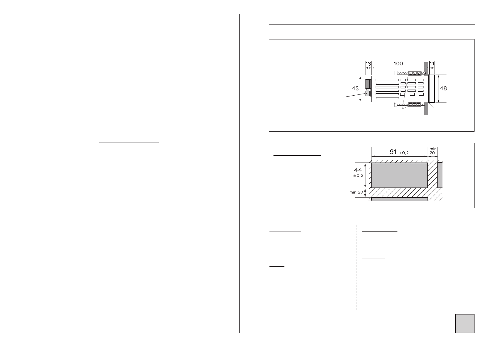
22.. SSPPAACCEE RREEQQUUIIRREEMMEENNTTSS
Case dimensions : (with terminals)
96 x 48 x 124 mm
Panel mounting
cut out 44 x 91 mm
external
seal
Fitting panel
max. thickness 30
case
tightenings
Terminals
• Power supply : (specify on order)
2 Versions : High Voltage or Low Voltage
High Voltage : 90...270 V
AC and 88 ...350 VDC 50/60/400 Hz
Low Voltage : 20...53 V
AC and 20...75 VDC 50/60/400 Hz
• Power draw : 7 W max. 10 VA max.
• Complies with standards EN 50081-2 on rejections and EN 50082-2;
on imunity (in industrial environment)
EN 61000-4-2 level 3, EN 61000-4-3 level 3,
EN 61000-4-4 level 4, EN 61000-4-6 level 3.
CE marking according to Directive EMC 89-336
Page 5
S
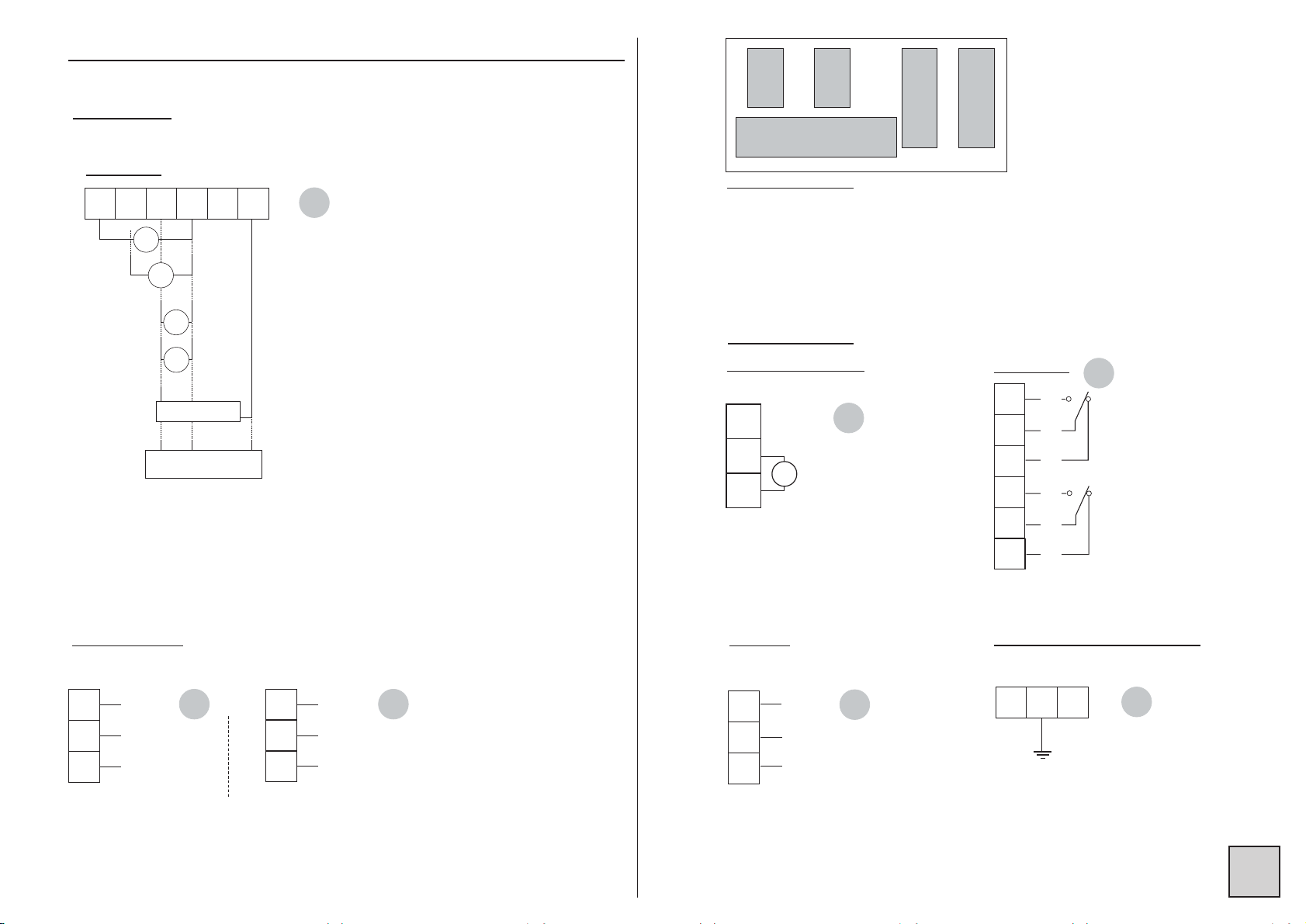
33.. WWIIRRIINNGG
20
21
22
1 2 3 4 5 6 7 8 9
Location of terminals
(view of case rear side)
23
24
25
26
27
28
29
30
31
32
33
34
35
36
37
C
E
D
B
A
4 5
6
1 2
3
7
8
9
-
~
~
+
AC
DC
INPUTS
OUTPUTS
(optional)
POWER SSUPPLY
300V
1V
10V
mV
mA
+ -
+ -
+ -
+ -
2-wire
transmitter
NC
3-wire
transmitter
+
-
IOUT
GND
VCC
26
27
28
29
30
31
2 RELAYS
T1
C1
R1
T2
C2
R2
T : ON
C : Common
R : OFF
0-4/20mA active
ACTIVE CURRENT
23
24
25
LOG 1
LOG 2
COM
LOGIC INPUTS
(optional)
20
21
22
DIGITAL
Data link RS 485
2 channels
32
33
34
LOG 1
LOG 2
COM
2 channels
B
A
COM
PROCESS
+ -
23
24
25
mA
RU
A
C
C E
D
B
A
Page 6
S
44.. PPRROOGGRRAAMMMMIINNGG
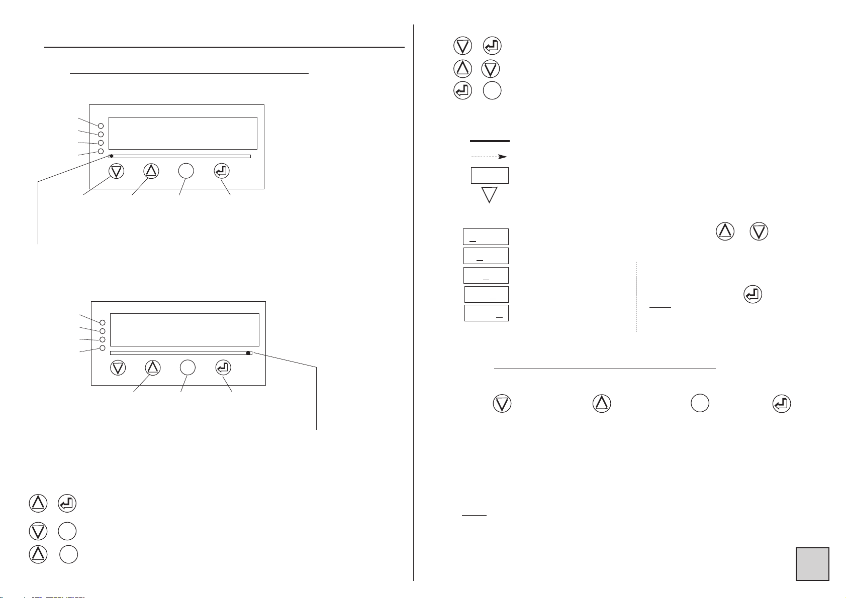
4.1 CCommunication wwith tthe iinstrument
Functions available from the instant measure :
Alarms
Led 1
Led 2
Led 3
Led 4
min. value
display
p21
Max. value
display
p21
min. and max.
zero reset
p22
Access to
the main
menu p6
Instant value display
Tare setting; (see p23)
Down scale display setting; (see p23)
Full scale display setting; (see p23)
Reading convention :
Move through main menu
Return to previous menu
Blinking display : awaiting validation or setting
Alternate information display
Entering of a parameter :
First start by increasing or decreasing
the 1st digit and the sign : from -9 to +9.
The 2nd from 0 to 9.
The 3rd from 0 to 9.
The 4th from 0 to 9.
The 5th from 0 to 9.
M
M
&
86888
86
588
865
28
8652
0
86520
«
Between each entering, validate
the cipher with key
Note
: The totalizer
parameters are entered on
6 digits.
Functions available from the totalizer :
Alarms
Led 1
Led 2
Led 3
Led 4
Display of the
oversteppings
counter.
(Hi.tot)
Access to
menu totalizer
zero reset
Access to
main
menu
Totalizer display
M
M
The Led under marking A blinks to indicate that
the displayed value is the instant value.
A B C D E F G H
The Led under marking H blinks to indicate that
the displayed value is the cumulated value.
A B C D E F G H
+
MM
MM
+
+
Further functions can be reached by pressing several keys :
Switching from instant value display to cumulated value display
and vice-versa;
Direct measure visualisation; (see p24)
Visualisation and setting of alarm setpoints; (see p24)
MM
MM
+
+
MM
MM
+
4.2 OOrientation tthrough pprogramming
Dialogue is ensured by the 4 keys located on the front face.
Move through
menus : downwards, or
decreasing of the
displayed value
Validation of
the displayed
parameter,
or access to
a sub-menu
Exit from a submenu to access
next menu /
access to the
programming
exit menu
Note
: In mode programming, the instrument will automatically resume
measuring with the previous configuration if no key is pressed during
1min.
MM
MM
Move through
menus : upwards,
or increasing of
the displayed
value
Only on the instant value display.
Page 7

S
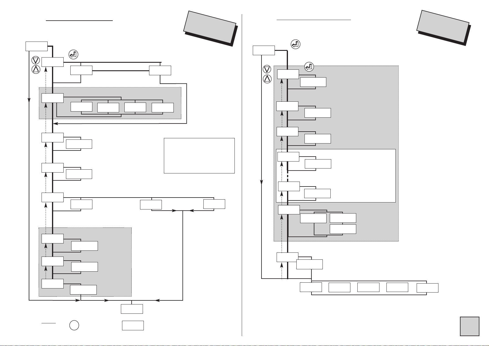
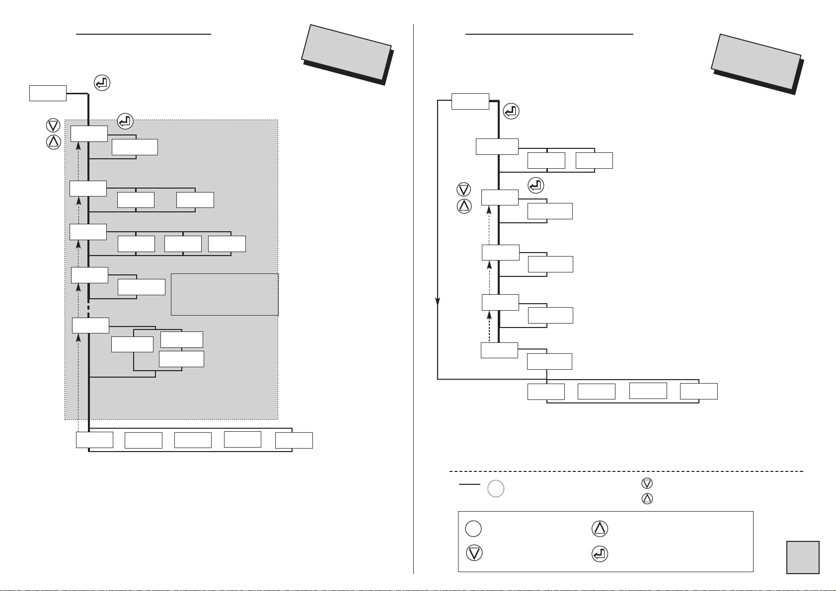
4.3 MMain mmenu
If code correct,
access to pro-
gramming
menu
Analog
output
simulation
Authorized by
access code
Erasing of
recorded
alarms
rEAd
ProG
CodE
88888
GEnE. CLEAr
«
«
«
«
«
Access code
programming
Display
simulation
instant or
cumulated
value, accor-
ding to type
of display
present before the access
to the menu
Authorized by
access code
(relay /analog
output)
(analog
output)
(relay output)
P.CodE
SIMUL
«
«
Tare zero
reset
Authorized by
access code
CLr.tA
«
menu
scroll
vertical
move
Entering of the access code.
The access to the programming
menu is protected by a 5-cipher
code.
The code on factory exit is 00000
(to change this code, see p20).
Configuration
reading
mode
M
M
4.4 PProgramming mmenu
(according to options)
dISPL.
totAl.
OUt.MA
JbuS
tor
rELAY
SECU
Pr.diS
SAvE
SAvE
Access to input programming p7
Access to the display factor programming p7
(instant value)
After programming the totalizer p8
Access to the analog output programming p8
(option analog output)
Access to the communication parameters p9
(option digital output)
Access to the programming of the LOGIC inputs p9
(option LOGIC inputs)
Access to the programming of the relays (2 relays) p10
(option relay output)
Access to the programming of the output, the relays, p11
in case of self-diagnosis and/or sensor rupture, and
access to disconnecting the sensor rupture
(option analog output or relays)
Access to the display programming : p12
Bargraph, display brightness
Access to the programming exit menu with or p13
without configuration saving
Note
:
⇒ Press to reach menu
⇒ In mode programming, the instrument will automatically resume measur-
ing with the former configuration if no key is pressed during 1min.
Move through menus / choice
InPut
Downwards move /
decrease
Validation / Vertical move
Menu exit / access
Upwards move / increase
M
M
Page 8
S
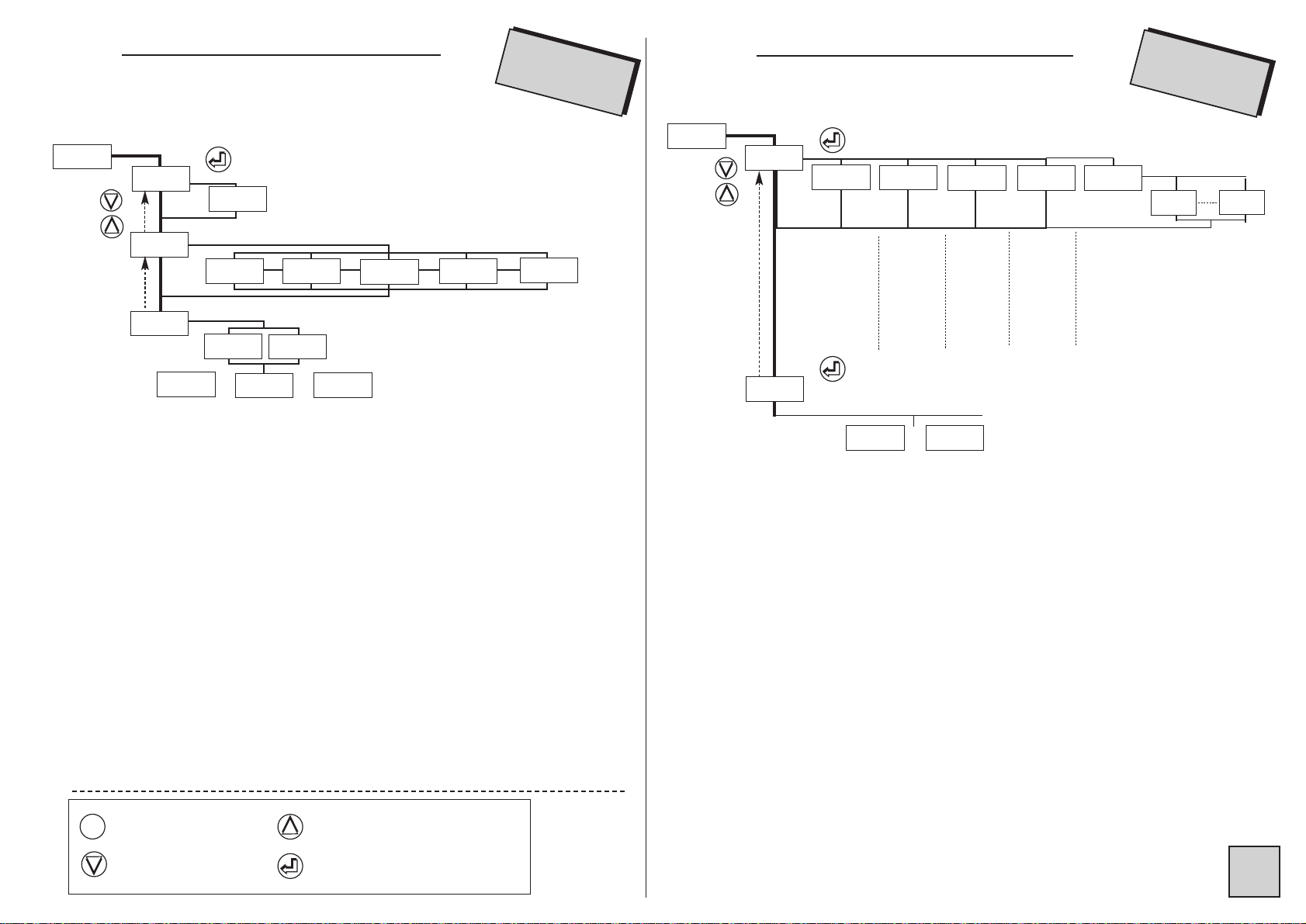
InPut
4.4.1 Input programming
voltage input
voltage input only
caliber choice
Special linearisation only
current input
down scale
-22.00 < x < 22.00 (mA)
-11.00 < x < 11.00 (10V)
-320.0 < x < 320.0 (300V)
-110.0 < x < 110.0 (0.1V)
-1.100 < x < 1.100 (1V)
from 1 to 18
linear
function
function square
root extraction
in mV, V or mA
according to
the type
special linear
function
M
M
diSPL.
Note :
Press key to reach menu
«
«
«
d.in
«
-888.88
«
root
diSPL.
U
MA
0-10
0-1300
0-0.1
«
LinEA.
«
nb
«
000018
«
A01
«
-888.88
«
A18
(1)
(1)
full scale
in mV, V or mA
according to
the type
«
F.in
«
-888.88
(1)
(1)
(1)
«
«
«
«
CALib
«
Li.SPE
«
Funct.
«
-888.88
«
tYPE
InPut
4.4.2 Displa
y programming
(instant value)
decimal point location
diSPL.
---.--
«
d.diSP
«
-88.888
«
F.diSP
«
-88.888
«
b01
display corresponding to
input down scale “d.in”
display corresponding to
input full scale “F.in”
setting in display points of
the same number of ordinates “bxx” and
abscisses “Axx”
setting in display
points
according to options
IntEG : coefficient from 0 to 10
integration indice
«
-88.888
«
b18
«
Cut.oF
«
-88.888
«
YES
«
-88.888
Out.MA
JbuS
tor
rELAY
«
IntEG.
«
000000
«
no
or or
or
or
«
«
Point
«
dISPL.
special linearisation
*
*
Changing this parameter
requires re-programming following parameters related to the
relays, the analog output, the
bargraph according to their dedication, as well as following
display parameters :
SPxx, hystx, do.diS, Fo.diS
d.bArG, F.bArG, d.diSP, FdiSP, bxx,
Cut.oF
SECU
Page 9
S
TotAl
totalizer decimal point
location
automatic
decimal pt
----.--
«
Auto.P
«
YES
«
nO
«
t.bASE
«
1
«
60
«
3600
«
Coeff
time setting for
the recording of
defects from 0 to
25.0
«
888.888
«
YES
«
88888.8
«
no
«
«
dP.tot
«
totAL.
*
coefficient setting from
±0,0001 to +999 999
or -99 999
«
M.deF.
according to options
Out.MA
JbuS
tor
rELAY
SECU
or or
or
or
* Changing this parameter
requires re-programming following parameters related to the
relays, the analog output, the
bargraph according to their dedication
SPxx, hystx, do.diS, Fo.diS
d.bArG, F.bArG,
«
8888.88
«
dO.diS
Out.MA
analog output down scale
analog output full scale
display corresponding to output down scale
display corresponding to output full scale
00.00 < x < 22.00 (mA)
00.00 < x < 11.00 (V)
according to options
JbuS
tor
rELAY
SECU
or
or
or
See also output features p17
(4)
(4)
(4)
Option aanalog ooutput
«
8888.88
«
8888.88
«
8888.88
«
d.out
«
In5tA
«
totAL
«
PArA.0
«
F.out
«
FO.diS
Out.MA
M
M
Note :
Press to go on to next menu
Move through menus / choice
Downwards move /
decrease
Validation / vertical move
Menu exit / access
Upwards move / increase
M
M
4.4.3 Totalizer programming 4.4.4 Analog output programming
integration time
parameter dedicated to the output
Page 10
S
4.4.5 Pro
gramming of the digital output
slave number
must be included between 1 and 255
transmission speed (baud rate)
switching
between
instant value
/ cumulated
value
function
min.
and
max. 0
reset
(instant
value)
function
display
hold
function
tare
(on
instant
value
only)
function totalizer
see p14
«
SLAvE
«
-8888
«
bAUd
JBuS
4.4.6 Pr
ogramming of
the LOGIC inputs
ToR
«
9600
«
4800
«
2400
«
1200
«
19200
tor
rELAY
SECU
or
or
or
rELAY
SECU
«
tArE
«
totAL
«
Fct1
«
Fct5
«
dSP.to
«
HoLd
«
CLr.M
time delay before any response
OFF : delay = 20ms
On : delay = 75ms
«
On
«
OFF
«
dELAY
See also the features of the
digital data link
See also the features of the LOGIC input
Option ddigital ooutput
Option LLOGIC iinputs
«
tor 1
«
tor 2
JBuS
tor
Idem Tor 1
Downwards move /
decrease
Validation / vertical move
Menu exit / access
Upwards move / increase
M
M
Page 11

S
«
rEL.1
rELAY
«
Acti.1
«
On
«
ModE.1
«
SP 1
0002.00
«
HYSt.1
0000.00
«
«
«
tiME.1
00000.0
«
LEd 1
«
SP1.1
«
0002.00
«
SP1.2
«
0004.00
rELAY
hysteresis
adjustable in display
points
0 < tIME < 025.0
in 0.1s increases
function alarm recording
function alarm message display
enter 4 characters + decimal point
if option 2 relays, at the end of menu REL.2,
access to or
choice of the state of the relay
associated Led
ON : led lit when relay active
OFF : led still when relay active
time delay on the relay
SPI.2 must be ≥ SPI.I
active
idem
rEL.1
de-activated
mode setpoint
mode setpoint
access to SP1
access to SP1.1
«
OFF
«
On
«
MEM.1
«
no
«
YES
«
MESSI
«
no
AbCd.
rEL.2
SECU
Pr.diS
«
«
«
YES
(5)
See also the
features of the
relay outputs
p17
Option ooutput 22 rrelays
«
tYPE.1
AlArM PULSE
InStA. totAL.
«
PArA.1
«
OFF
if mode window programmed
if mode setpoint programmed
«
rEL.2
«
P.rAt
00000
«
P.tiME
100 200 400
setting of the pulse weight from
-10 000 to +10 000
pulse time in ms
operating mode
parameter dedicated to the alarm
4.4.7 Programming of the relay outputs
Page 12

SECU
S
See also the safety features p18
option
2 relays
if mV input
option analog output
if return value entered
if input mV or mA (if d.in and F.in> 3.5mA)
«
rEL.1
«
LO
HI
«
OFF
out.MA
state of relay 1 in case of sensor rupture
«
LO
HI
«
OFF
state of the relay in case
of sensor rupture
«
sensor rupture disconnection
«
YES
«
«
no
rEPLi
output value in case of sensor rupture
00.00<rEPLI<22.00 (mA)
«
OFF
«
On
OFF : sensor rupture inactive on the relay
In case of sensor rupture
LO : relay de-activated
HI : relay active
«
8888.88
option 2 relays
option analog output
if return value programmed
«
LO
HI
«
OFF
out.MA
state of relay 1 in case
of error self-diagnosis
«
«
YES
«
«
no
rEPLi
output value in case of self-diagnosis error
00.00<rEPLI<22.00 (mA)
OFF : self-diagnosis
inactive on the relay
In case of self-diagnosis
LO : relay de-activated
HI : relay active
«
8888.88
Pr.diS
«
ruPt.
«
SECU
«
dIAG.
«
«
«
rEL.1
«
«
CAPt.
«
rEL.2
«
LO
HI
«
OFF
state of the relay in case of
error self-diagnosis
«
rEL.2
«
*
*
*
*
*
If the relay is programmed in
mode pulses, its state on sensor
rupture or self-diagnosis is blocked on OFF.
4.4.8 Pr
ogramming of the safeties
Page 13

S
Pr.diS
«
On
«
OFF
«
YES
«
no
1 1 1 1
«
b.bArG
1 1 1 1
«
L.dIG
«
nuLL
SAvE
«
000600
«
d.bArG
«
000200
«
F.bArG
adjusting of the display brightness
on 4 levels
on 4 levels
bargraph and leds brightness
not enforced to
zero
erasing of unsignificant zeros
display corresponding to
0% of the bargraph
display corresponding to
100% of the bargraph
state of the last digit (right hand side)
(enforced to zero)
See also the display features p15
«
br.diG
Pr.diS
«
InStA.
«
totAL.
«
Indic.
«
PArA.b
«
no
«
tor 1
«
no
«
rS
«
LEdd
«
no
«
tArE.
«
LEdE
«
LEdb
«
no
«
tor 2
«
LEdC
function associated with led b
function associated with led c
function associated with led d
function associated with led e
«
no
«
M.dEF
«
LEdF
function associated with led f
«
no
«
dEP.to
«
LEdG
function associated with led g
no : no dedication
tArE : led lit if a tare has been
entered
no : no dedication
M.dEF : led lit in case an error has
been recorded
no : no dedication
dEP.to : led lit if overstepping on the
1st totalizer
>999 999 or < -99 999 (Hi.tot ≠ 0)
no : no dedication
tor 1 : led b dedicated to the
indication of logic input 1
no : no dedication
tor 2 : led c dedicated to the
indication of logic input 2
no : no dedication
rS : led lit in case of RS transmission
Choice of the bargraph operating mode
insta : on the instant value
total : on the totalizer
indic : use of the bargraph to indicate some functions
4.4.9 Programming of the brightness,
the displays and the bargraph
Page 14

S
SAvE
MA
SAvE
no
YES
exit with configuration saving
exit without
configuration
saving
revert to measure
display
4.5.1 Current input
• Linear :
Features
Measurable input limits : -22 to 22 mA
•
Unlinear :
Square root extraction
Note : The function square root extraction tends to amplify the input
signal background noise on getting near zero.
To avoid the ripples caused by this noise, just programme a cut-off value
(in display points), see p14.
Special linearisation :
For specific applications such as volume measurements, the meter can
memorise an unlinear curve programmable in X and in Y.
4.5 IInput ffeatures aand pprogramming llimits
«
root
«
Caliber
Display
resolution
Input stage
resolution
Accuracy
from -20 to
+20mA
± 1 digit 16 bits 0.05% of MR
Li.SPE
«
The curve resulting from your equation can be replaced by a series of
linear segments, with a maximum of 20 points
(19 segments).
Note
: The values of the abscises (x) have to go increasing d.in < value
of A01 < value of A02...< F.in.
Example
:
Say a layed cylindric tank, 1 meter high (h) and 1 meter long (l). A linear
0-20 mA sensor measures the height of the liquid surface line :
Meter input : height h
0 meter -> 0 mA (empty tank)
1 meter -> 20 mA (full tank)
with cos β/2 = (R-h)/R
Sin β /2 = C/2R
Meter display :
Empty tank volume d.diSP = 0.000
Full tank volume F.diSP =0.785
Volume = L [
π R² β /360 - C(R-h)/2]
Hence a curve of 10 equally long segments :
Etendue de mesure / nr of segments = 20mA/10 = 2mA length of
the segment. For 10 segments nb = 9 (11 points to be programmed,
including d.in and F.in).
Input
mA
d.in 0
A01 2
A02 4
A03 6
A04 8
A05 10
A06 12
A07 14
A08 16
A09 18
F.in 20
0.0
0.1
0.2
0.3
0.4
0.5
0.6
0.7
0.8
0.9
1.0
0.00
73.74
106.26
132.84
156.93
180.00
203.07
227.16
253.74
286.76
360.00
0.00
0.60
0.80
0.92
0.98
1.00
0.98
0.92
0.70
0.60
0.00
0.000
0.041
0.112
0.198
0.293
0.393
0.492
0.587
0.674
0.745
0.785
d.diSP
B01
B02
B03
B04
B05
B06
B07
B08
B09
F.diSP
00.00
01.04
02.85
05.04
07.47
10.00
12.54
14.96
17.17
18.98
20.00
Height
m
Degree
Chord
m
Volume
m
3
Outps.
in mA
β
(R)
L (length)
C (chord)
R (ray)
h
(height)
Note : Exit from mode programming with configuration saving (SAvE, YES) will
automatically reset to zero the tare, the min. and max. and the recording of
alarms, as well as the pulse output buffers.
In case of modification of the decimal point location of the instant value or of
the totalizer, the instrument will propose after
SAvE YES all the decimal point rela-
ted parameters which have not been modified.
A
SAvE YES will not reset the totalizer to zero. If its parameters have been chan-
ged it will have to be reset to zero, in order to avoid an incoherent counting
(see p22).
4.4.10 Programming exit with or without saving
Page 15

S
Programming :
d.in = 0 mA F.in = 20 mA
nb = 9
d.disp = 0,000 m3F.disp = 0,785 m
3
Programming from A01 to A09 and from B01 to B09 according to table.
4.5.2 V
oltage input
• Linear : Features
0 2 4 6 8 10 12 14 16 18 20
0 0.1 0.2 0.3 0.4 0.5 0.6 0.7 0.8 0.9 1
20
18
16
14
12
10
8
6
4
2
0.11
0.04
0.20
0.29
0.39
0.49
0.59
0.67
0.75
0.79
volume
in m
3
output (mA)
Y
X
input (mA)
height (m)
U
«
Caliber
Display
resolution
Input stage
resolution
Accuracy
-100 to +100 mV
-1 to + 1 V
-10 to +10 V
-300 to 300 V
± 1 digit 16 bits 0.05% of MR
• Unlinear : (see p13)
Measurable limits : -5% to +5%
Example for caliber 1V : -1.1V to +1.1V
4.5.3 Instant v
alue displa
y :
Decimal point location for the instant value display
(4 decimals maximum).
Display corresponding to input down scale
Display corresponding to input full scale
Setting in display points of the ordinate for point Axx for
a special curve input (see unlinear input)
Expressed in display points.
− If display full scale > display down scale and if display ≤ cut off value,
then it is maintained at down scale.
− If display full scale < display down scale and if display ≥ cut off value,
then it is maintained at down scale.
••
Response time
:
Digital filtering integration indice :
Programmable from 0 to 10; to be used in case of unsteady input.
2 cycle times, i.e. 240 ms must be added to obtain the maximum response
time.
Note
: For the analog output response time, add 40ms to the values
shown in the table.
For the relays : add the time delay programmed on the alarms.
Point
d.diSP
F.diSP
bXX
Cut.oF
intEG
Typical response
time at 90%
120 ms 400 ms 600 ms
intEG
0 1 2
1 s
3
1.4 s
4
2 s
5
3 s 5 s 7.5 s
6 7 8
10 s
9
15 s
10
Page 16

Parameter applied to the bargraph
Bargraph on the instant value
Bargraph on the cumulated value
Bargraph in mode indication
Led marking b
No dedication (led still)
Led lit when logic input 1 is active
S
4.5.4 Totalizer
Totalizer decimal point location
(4 decimal maximum)
Fix decimal point
Automatic decimal point
Decimal point : The totalizer is displayed with a maximum of decimals, and the decimal point will move as the total increases, until
the number of decimals programmed in
Dp.tot is reached
eg. : programming of the decimal point = -.-on starting the totalizer indicates 00.0000. When it reaches
99.9999 it will indicate 100.000, and then 1000.00.
Integration time basis
: 1 sec : 60 sec : 3600 sec
Convertion coefficient : coefficient to be applied on the
instant value to calculate the cumulated value, adjustable
from ± 0.0001 to 999 999 or -99 999.
Eg. : if the instant value represents m
3
and you want to total up
liters, the coefficient will be equal to 1000.
Recording of defects.
No recording
Recording of defects (input electrical oversteppings or
sensor rupture) if defect present on the input during a time
≥ pro-
grammed time. Programming of the time from 0 to 25.0 sec, in 0.1
sec. increases.
Display of error messages alternating with the cumulated value if
recording. To reset the recording to zero, see p22 .
Dp.tot
Auto.P
no
yes
no
yes
t.BASE
1 60 3600
CoEFF
M.dEF
br.diG
1 1 1 1
4444
1 1 1 1
4444
br.bAr
L.dIG
nuLL
nuLL
YES
••
Last digit inhibition (low weight)
In mode programming, the menu L.dIG allows suppressing of the last
digit display, the latter being enforced to 0 if OFF is validated.
••
Erasing of unsignificant zeros
Suppresses the display of unsignificant zeros on the
left hand side.
Eg.
: Display value 0015
Display 0015
Display 15
Eg.
: Display value 00.15
Display 00.15
Display 0.15
••
Setting of the bargraph brightness
Lowest brightness Strongest brightness
The brightness level is visualised directly on the bargraph.
Caution : during setting, the bargraph no longer represents measure,
including also in mode reading.
=
nuLL
no
YES
=
=
nuLL
no
YES
=
=
4.5.5 Diplay features :
••
Adjusting of the digits brightness
Lowest brightness Strongest brightness
PArA.b
InStA
totAL
Indic
LEdb
no
tor1
••
Bargraph display factor
Display corresponding to the still bargraph (0%)
Display corresponding to the fully lit bargraph (100%)
In case of overstepping, the bargraph will start to blink. A sensor rupture
is indicated on the bargraph (if dedicated to the instant value) by the
lighting of one led out of two.
d.bArG
F.bArG
Page 17

S
Led marking e
No dedication (led still)
Led lit when a tare has been entered
Led marking f
No dedication (led still)
Led lit if defect recorded
Led marking g
No dedication (led still)
Led lit if overstepping of the 1st totalizer
-99 999 > counting > 999 999
(Hi.tot ≠0)
LEdE
no
tArE
LEdF
no
M.dEF
LEdG
no
dEP.to
Led marking c
No dedication (led still)
Led lit when logic input 2 is active
Led marking d
No dedication (led still)
Led lit during answering of the instrument on
the RS
LEd C
no
tor2
LEdd
no
RS
Switching to the cumulated value display if LOGIC activated,
if not instant value display.
Function on the totalizer
meter zero reset on ascending front, and counting.
zero reset on ascending front, and counting on low level
only
diSP
totAL
Fct1
Fct2
Fct3
24VDC
0V
counting counting counting
meter meter
zero reset zero reset
24VDC
0V
counting counting stopped counting
meter meter
zero reset zero reset
zero reset on ascending front, and counting on high level
only
Counting on high level only (no reset)
Counting on low level only (no reset)
24VDC
0V
counting counting stopped
meter meter
zero reset zero reset
24VDC
0V
counting counting stopped counting counting stopped
Fct4
24VDC
0V
counting stopped counting
Fct5
4.5.6 L
OGIC inputs
(optional)
• Board of 2 LOGIC inputs : Input signal 24 Vdc
Possible functions :
Holding of the instant value display in case of activation of the
LOGIC function. The display and the analog output if it is dedicated to the instant value remain fixed in case of variation of the input
signal. The relays and the totalizer carry on reacting to the input signal.
Min. and max. zero reset. The activation of the LOGIC
function resets the min. and max. to zero
Activation of function tare.
The meter switches to mode tare, the tare being the display
value present at the time of this activation.
HoLd
CLr.M
tArE
Page 18

S
4.6 OOutput ffeatures aand pprogramming llimits
4.6.1 Analog output
Current output 0/4-20mA active
• Accuracy 0.1 % in relation to the display (at +25°C)
• Residual ripple ≤ 0.2%
• Admissible load 0Ω≤ Lr ≤ 500Ω
• Programmable scale ratio with enlarging effect
• Response time : 40 ms in relation to the display
Out.MA
Parameter applied to the output
Output on the instant value
Output on the cumulated value
Analog ouput down scale (eg. 04.00 (4mA))
Analog output full scale (eg. 20.00 (20mA))
Display value corresponding to output down scale
Display value corresponding to output full scale
In mode measurement, the analog output can not overstepp 10% of the
greatest of the 2 values : d.out and F.out
F.out
dO.diS
FO.diS
d.out
TotAL
InStA
PArA.0
4.6.3 Relay outputs :
2 relay outputs
• Relays programmable independently in mode alarm, or as pulses output
• NO-NC contact 8 A - 250 V on resistive load
rEL.1
rEL.2
4.6.2 Digital output
:
- Data link RS485 (2 wire)
- Protocoles MODBUS-JBUS format of data : integer and double integer
- Exclusive transmission format : 1 bit start
8 bits without parity
1 bit stop
Slave number between 1 and 255
Transmission speed between 1200 and 19200 bauds
Time delay before any response
Complete description of option MODBUS : see annexe documentation : MODBUS/JBUS.
Including : table of modbus addresses, used functions, description of the
configuration bytes and advanced functions.
SLAvE
bAud
dELAY
Activation or de-activation of relay x
The state of relay x depends on the carried programming
Relay x remains still.
Choice of relay x operating mode
Mode alarm
Mode pulses
Parameter applied to alarm X
Alarm X on the instant value
Alarm X on the cumulated value
Act.X
On
OFF
tYPEX
AlArM
PulSE
PArA.X
InStA
totAL
Choice of the operating mode
••
Mode setpoint
OFF
ON
setpoint setpoint
Legend :
ON coil supplied
OFF coil not supplied
or
OFF
ON
ModE.x
Mode alarm
••
Mode window
OFF
OFF
OFF
ON
ON
ON
setpoint
set-
point
set-
point
or
SPX.2
SPX.1
SPX.2
SPX.1
Page 19

S
••
Mode setpoint
••
Mode window
Choice of the state of the relay associated led
The led indicates the alarm state.
Led lit when relay active (coil supplied)
Led still when relay active (coil supplied)
Hysteresis setting in display points .
The hysteresis is active on switching from lit led to still led; i.e.
on switching out of alarm, as the led represents the alarm state.
SP.X
SP.X
- Hystx
HYSt.x
LEdx
On
OFF
led lit
SPX.1
SPX.1
-Hyst.x
SPX.2
SPX.2
+Hyst.x
led lit
led still
led still
led still
CLEAr
MESSx
••
Display of alarm messages
A programmed alarm message can be made to appear alternating with
measure. The message will appear only during the alarm state, while the
associated led is lit.
••
Setting of setpoints : There are 2 ways to adjust setpoints.
- either in mode programming entering the correct access code
- or by pressing simultaneously on and if the access to quick
entering has been authorized during the code programming (see p20).
M
M
tiME.x
MEM.x
••
Time delay on the alarm
The time delay on the relay si adjustable from 000.0 to 025.0s, in 0.1s
increases
It is active both on switching and switching back.
••
Alarm recording
Allows recording of the alarm after a setpoint has been passed. Once
measure reverts below the alarm setpoint, the relay remains on and the
led blinks to warn the user that a setpoint has been passed (to reset the
recording of alarms to zero see menu p21).
Note
: Exit from mode programming wih configuration saving will reset
alarm recordings to zero.
Weight of the pulse to be applied on the totalizer unit
adjustable from -10 000 to +10 000.
eg. :
1 : one pulse at each increase of the totalizer unit
-1 : one pulse at each decrease of the totalizer unit
1000 : one pulse every 1000 increases of the totalizer unit
-1000 : one pulse every 1000 decreases of the totalizer unit
Pulse duration : 100ms, 200ms or 400ms.
Note : The programmed pulses duration applies both to the high and low
level, in order to allow some time between two consecutive pulses. When
the pulse frequency is too high in relation to the output capacity, they are
stored in a buffer, and restituted as soon as the frequency drops again. A
(
SAVE, YES), a totalizer zero reset or a power supply cut will reset the buf-
fers to zero.
P.rAt
P.tiME
Mode pulses
diAG
4.6.4 Safeties :
••
Self-diagnosis
:
The meter permanently watches any drifts that may surge on its components. The self-diagnosis serves to warn the user in case of abnormal
increase of these drifts, before they provoque false measures.
The self-diagnosis error information can be reported
:
· On the display
: An error message appears alternating with measure;
an error code is registered and can be read in menu About
Page 20

S
ruPt
OFF
OPEn
LO
HI
· On the analog output
If a return value has been programmed
Value included between : 0 and 22 mA
••
Sensor rupture
The sensor rupture can be detected on mV and current inputs if down
and full scale > 3.5 mA.
The sensor rupture information can be reported
:
· On the relay
No influence of the sensor rupture on the relay
Relay de-activated (coil not supplied) in case of sensor
rupture
Relay active (coil supplied) in case of sensor rupture
Note
: The led is either still or lit, according to its programming in menu
rELAY.
If the relay is programmed in mode pulses, its state on sensor rupture and
self-diagnosis error is blocked on position OFF.
· On the analog output
If a return value has been entered
Value between : 0 and 22 mA
OFF
LO
HI
· On the relays :
No influence of a self-diagnosis error on the relay
Relay de-activated (coil not supplied) in case of self-diagnosis
error
Relay active (coil supplied) in case of self-diagnosis error
Note : The led is either still or lit, according to its programming in menu
rELAY.
If the relay is programmed in mode pulses, its state on sensor rupture and
self-diagnosis error is blocked on position OFF.
••
Sensor rupture disconnection (If mV input)
The sensor rupture can be disconnected, in order not to disturb some
calibrators which may be sensitive to the rupture detection current.
In menu :
Activation of the sensor rupture, or not
Sensor rupture active
Sensor rupture disconnected
CAPt
SECU
OFF
On
rEAd
rEAd
InPut
diSPL
Out.MA
JbuS
totAL
rELAY
tor
Pr.diS
About
4.7 CConfiguration rreading
Reading of the input parameters
Reading of the instant measure display
parameters
Reading of the totalizer parameters
Reading of the analog output parameters
(option analog output)
Reading of the communication parameters
(option digital output)
Reading of the LOGIC input parameters
(option LOGIC input)
Reading of the alarm parameters
(option 2 relays)
Reading of the safety parameters for sensor
rutpure or self-diagnosis on the outputs
Reading of the display programming
parameters (leds, bargraph leds...)
Reading of the intrument’s own parameters
In each reading sub-menu, use keys and to move, and key
to visualise parameters
If no key is pressed during 20 s., the instrument will automatically
revert to measure display.
Validation /
Vertical move
SECU
Coding :
1 : Programming error
2 : Gain error
4 : Offset error
8 : Input calibration error
16 : Output calibration error
If the instrument detects for instance an offset error (4) and a gain error
(2) the error code value will be 6 (4+2).
· On the display
: Message
Note
: The sensor rupture detection has priority over the self-diagnosis.
Page 21

4.8 AAccess ccode
An access code adjustable from 00000 to 59999 serves to protect the
meter from unauthorized programming, and to lock access to some
functions.
00000 Factory code
x x x x x
0 to 5 Access to display shifting
6 to 9 No access
0 to 5 Access to display and output simulations
6 to 9 No access
0 to 5 Access to function “tare”
6 to 9 No access
0 to 5 Access to quick entering of alarm setpoints
6 to 9 No access
0 to 2 Access to the totalizer zero reset menu
3 to 5 No access
S
About
C95 CI
n
0
A0123
ProG
0 1.05
0Pt10.
Ar--.
Err.
0000
CH.SUM
FC4E
Validation / Vertical
move
instrument type
Sub-menu
instrument number
programme version
code of installed
options
error code in case of
error self-diagnosis
check sum of the
flash memory
X1 : - : No analog output
A : Analog output
X2 X3 : - - : No relay output
r- : Output 2 relays
X4 : - : No RS output
n : RS output
X5 - : No LOGIC input
t : 2 LOGIC inputs
00000
XXXXX
1 2 3 4 5
.
00000
XXXXX
1 2 3 4 5
.
4.9 PProgramming oof aa nnew aaccess ccode
P.CodE
no
Enter pre-
vious code
if code incorrect
(old)
display during 2s.
and revert to measure display
display during 2s.
if new code
≥60 000
if new code < 60 000
new code registered
Revert to measure
display
if code correct
(old)
Enter new
code
no
Reminder : If no key is pressed during 1 min, the instrument will automatically revert to measure display.
SIMUL
SIMUL
Display value
if
M
M
Pressing on
menu reverts
to measure
display.
4.10 FFunctions aaccessible iin tthe mmain mmenu
4.10.1 Display simulation
(accessible according to programmed access code and if option
relays or analog output)
The display canbe simulated with the meter in order to validate the
configuration of the analog output, alarm and pulse outputs in the installation.
The simulated display corresponds to the one (instant or cumulated
value) which was on display at the time of the access to this menu (the
blinking led A or H indicates the type of this value).
Enter new display value
Page 22

S
GEnE.
GEnE.
Output value
if
Enter value to
be injected
M
M
Pressing menu
reverts to
measure
display.
Note : The instrument carries on measuring during the simulation.
Only the analog output no longer reacts to measure.
CLEAr
4.10.3 Menu :Erasing of recorded alarms
If the function recording of alarms has been programmed, the relay
state will be recorded after a setpoint has been passed.
If the setpoint is passed back the other way, the relay state does not
change and the corresponding led starts to blink.
To come back to the normal state (led not blinking and relay in the correct state) use menu CLEAr.
M
M
CLEAr
recorded alarms are not
erased
erasing of recorded
alarms, and revert to
measure display
Reminder
: If no key is pressed during 20 s.,
the instrument will revert to measure display.
Note : Exit from mode programming with configuration saving will reset
alarm recordings to zero.
(accessible according to programmed access
code and if option analog output)
4.10.2 Analo
g output simulation (mode generator)
CLr.tA
4.10.4 Menu : Deleting of the programmed tare
M
M
CLr.tA
the recorded tare is not
suppressed
deleting of the recorded
tare, and revert to measure display
Reminder
: If no key is pressed during 20 s. , the instrument will
automatically revert to measure display.
Note : Exit from mode programming with configuration saving will
reset the tare to zero.
(accessible according to programmed access
code)
5.1 FFunctions wwhich rrequire ppressing oonly 11 kkey :
5.1.1 On instant value display
a / min. value display b/ Max. value display
InF.
02.00
Measure
display
Alternate information display
Minimum value
55.. FFUUNNCCTTIIOONNSS AACCCCEESSSSIIBBLLEE DDIIRREECCTTLLYY FFRROOMM
DDIISSPPLLAAYY
SUP.
08.00
Measure
display
Alternate information display
Maximum value
Note : The instrument does not measure during the simulation. The analog outputs, the alarm, the pulse outputs and the bargraph will react
according to the value entered for simulation purpose.
The totalizer stops during the simulation. It is saved, and will then be
restored.
If alarm messages have been programmed, they may appear during the
simulation.
Page 23

S
c / Deleting of maximum and minimum values
M
M
CLr.M
Measure
display
revert to measure display.
Reminder
: If no key is pressed during 20 s.,
the instrument will revert to measure display.
Note
: Exit from mode programming with configuration saving
will reset min. and max. values to zero
Deleting of recorded min. and
max., and revert to measure
display
5.1.1 On the totalizer display
a) Totalizer upper part display
Hi.tot
0010
Totalizer
display
number of overteppings on the
totalizer
The cumulated value is :
Hi.tot x 1 000 000 + totalizer value if totalizer ≥ 0
and Hi.tot x -100 000 + totalizer value if totalizer < 0
b) Access to the totalizer zero reset menu
rdEP
r.totA
Totalizer
display
Zero reset of error
recordings
Zero reset of the
totalizer, Hi.tot and
of error recordings
Access only if user code
<30 000
5.2 FFunctions wwhich rrequire ppressing sseveral kkeys
:
5.2.1 Display shifting (only on the instant value display)
(accessible according to programmed access code)
M
M
Display down scale shifting (AdJ.Lo)
Display full scale shifting (AdJ.Hi)
After injecting an input signal corresponding to the down (or full) display
scale, press simultaneously on keys and (or and ) The
message AdJ.Lo (AdJ.Hi) will appear alternating with the value, to indicate you are in menu adjustment.
The display down and full scale can be increased or decreased by pressing or .
Keep pressing during 3s. on key or to access a fast increasing or
decreasing of the display value.
Press to validate the shifting. Once all shiftings are validated, the
input thus shifted will keep its shifting even after a setting off tension.
Press (or do not press any key during 20 s) to revert to the
measure display without modifications.
M
M
M
M
Page 24

S
5.2.2 Tare setting (only on instant value display)
Press and to enforce the signal present on the input as display
down scale
Note : The tare is not recorded in case of power supply cut.
To suppress the tare, go into menu in the main menu p6.
Exit from mode programming with configuration saving will automatically
reset the tare to zero.
(accessible according to programmed access code)
d.dISP
CLr.tA
5.2.4 Direct measure visualising
Press and to visualise the signal directly without any processing
: scale factor, square root, linearisation
− in mV, V or mA.
M
M
5.2.3 Changing of the display
ed value
Press and to switch from the instant value to the totalizer, and
vice-versa.
Led marking A blinking : instant value.
Led marking H blinking : totalizer
5.2.5 Visualisation and setting of alarm setpoints
Setting of setpoints : There are 2 ways to adjust setpoints.
- either in mode programming entering the correct safety access code
- or by simultaneous pressing on and
MM
MM
Option 22 rrelays
MM
MM
The meter will then show the message SP.x or SPx.x alternating with
the value of the corresponding setpoint.
The various setpoint values can be accessed by or .
These setpoints can then be changed (according to the programmed
access code, see p20) pressing
Once the setpoint is adjusted, press to revert to the setpoints reading menu.
Once all setpoints are adjusted, just press and the meter will revert
to mode measure, taking the new values into account.
If no key is pressed during 60 s., the meter will revert to measure
display without taking the modifications of setpoint values into account.
66.. EERRRROORR oorr iinnddiiccaattiioonn MMEESSSSAAGGEESS
2000
OPEn
Err.1
Value in overstepping
Sensor rupture
«
01000
Counting overstepping
> 999 999 999
or < -99 999 999
«
----
O.L.
Er.xxx
Input upper or lower electrical
overstepping
Displayable value overstepping.
Self-diagnosis error
Value set out of range
On instant value display
On totalizer display
totalizer
OPEN -----
Electrical overstepping or
sensor rupture recorded.
or
Page 25

S
77.. GGEENNEERRAALL WWAARRRRAANNTTYY TTEERRMMSS
WARRANTY applying and duration
This appliance is garanteed for a duration of 1 year against any design
or manufacturing defects, under normal operating conditions.
Processing conditions * : Processing not under warranty will be submited to the acceptance of a repair estimate. The customer will return
the products at his charge, and they will be restored to him after processing. Without a written agreement on the repair estimate within 30
days, products will not be held.
* Complete warranty terms and details available on request.
88.. LLEEXXIIQQUUEE
Messages shown by the meter in mode programming and/or reading
GGeenneerraall aacccceessss
Access to the reading of the parameters
Access to the programming of input and output parameters
Code for access to the programming of input and output
parameters
Programming of a new access code
Access to display simulation
Access to a simulation of the analog output
Deleting of recorded alarms
Tare suppressing
rEAd
ProG
CLEAr
CLr.tA
CodE
SiMUL
P.CodE
GEnE
0-10
300
0-0. 1
Input 0 to 10 V (or -10/10V)
Input 0 to 300 V (or -300/300V)
Input 0 to 100 mV (or -100/100mV)
Input 0 to 1 V (or -1/+1V)
Input down scale
Input full scale
Choice of the processing function
Linear
Square root extraction
Special linearisation
Number of linearisation points
Abscisse of a special linearisation point
0-1
d.in
F.in
nb
Axx
Funct
LinEA.
Li.SPE
root
CALib
IInnppuuttss
Access to the input programming sub-menu
Input type
Voltage input
Current input
Choice of the voltage caliber
InPut
tYPE
MA
U
diSPL.
Point
--.-d.diSP
F.diSP
bxx
Cut.oF
IntEG.
Instant value
Access to the display programming sub-menu
Choice of the decimal point location
Decimal point location
Display down scale
Display down scale
Ordinate of a special linearisation point
Cut-off programmable or not
Integration indice
Totalizer
Choice of the decimal point location
Decimal point
Choice of the decimal point operating mode
fixed decimal point
automatic decimal point
dP.tot
----.-
no
Auto.P
yes
Page 26

LOGIC inputs
Access to the LOGIC inputs programming sub-menu
Programming of LOGIC input 1
Programming of LOGIC input 2
Function erasing of min. and max.
Function display holding
Function Tare
Totalizer display / instant value display
Function on the totalizer
Function type X
S
FctX
tor
tor 1
tor 2
CLr.M
HoLd
tArE
dSP.to
totAL
Choice of the time basis
second
minute
hour
Convertion coefficient
Recording of errors, or not
t.baSE
CoeFF
MdeF
1
60
3600
Pr.diS
br.diG
br.bAr
1 1 1 1
4444
1 1 1 1
4444
L.dIG
On
OFF
nuLL
no
YES
Display parameters
Display features programming sub-menu
Adjusting of the digits brightness (4 levels)
Lowest brightness Strongest brightness
Adjusting of the bargraph brightness
Lowest brightness Strongest brightness
Last digit (low weight)
Last digit in service Last digit enforced to 0
Deleting of unsignificant zeros
Yes No
Display corresponding to an extinguished bargraph (0%)
Display corresponding to a fully lit bargraph
(100%)
Bargraph in mode indication
Led marking b
No dedication (led still)
Led lit when LOGIC input 1 is active
Indic
LEdb
no
tor1
d.bArG
F.bArG
Led marking c
No dedication (led still)
Led lit when LOGIC input 2 is active
Led marking d
No dedication (led still)
Led lit during RS response from the
instrument
LEd C
no
tor2
LEdd
no
RS
Parameter applied to the bargraph
Bargraph on the instant value
Bargraph on the cumulated value
PArA.b
InStA
totAL
Led marking e
No dedication (led still)
Led lit when a tare has been entered
Led marking f
No dedication (led still)
Led lit in case an error has been recorded
Led marking g
No dedication (led still)
Led lit in case of totalizer ovestepping
-99 999< counting > 999 999
LEdE
no
tArE
LEdF
no
M.dEF
LEdG
no
dEP.to
Analog
Access to the current output programming sub-menu
Parameter applied to the output
Out.MA
PArA.O
Page 27

S
Output on the instant value
Output on the cumulated value
Analog output down scale
Analog output full scale
Access to programming of the display for output down scale
Access to programming of the display for output full scale
d.out
F.out
InStA
totAL
dO.diS
FO.diS
19200
dELAY
Digital output
Access to the RS output programming sub-menu
Slave number
Transmission speed (baud rate)
Possible speeds
Possible speeds
Time delay before any response
Delay 75ms Delay 20ms
bAud
SLAuE
1200
JbuS
OFF
On
Setpoint value in mode setpoint
1st setpoint value in mode window
2nd setpoint value in mode window
Hysteresis value in display points
Time delay on relay X
SPx.1
SPx.2
HYSt.x
tiME.x
SPx
Relay outputs : x : 1 à 2
Access to the relay outputs programming sub-menu
Access to the programming of relay x
Activation of relay output 1
Activation De-activation
Relay operating mode
Mode alarm
Mode pulses
Parameter applied to the alarm
Alarm on the instant value
Alarm on the cumulated value
Relay x operating mode
Mode setpoints
Mode window
OFF
ModE.x
__1
--
--
1__
ActiX
tYPE.X
PArA.X
ALArM
PuLSE
inStA
totAL
rEL.x
On
rELAY
_1--1_
-
1__1
-
Programming of the relay associated led
Led lit when relay active (coil supplied)
Led still when relay active (coil supplied)
Recording of alarm X
Recording No recording
Alarm message
Message No message
Pulse weight
LEdx
On
OFF
MEM.x
MESSx
P.rAt
no
YES
no
YES
Pulse duration
100 ms
200 ms
400 ms
P.time
100
200
400
rEL.X
OFF
rUPt
CAPt.
OFF
LO
H I
SECU
Safeties
Access to the safeties programming sub-menu
Programming of the sensor rupture safety
Sensor rupture activation (or not)
De-activated Active
State of relay X in case of sensor rupture
No sensor rupture associated with the relay
Relay de-activated in case of sensor rupture
(coil not supplied)
Relay active in case of sensor rupture
(coil supplied)
On
Page 28

Reading of the instrument internal features
Access to the internal features reading sub-menu
Instrument type : C95 CI
Identification number
Programme version
Programme version number
Option code
Option code value
Self-diagnosis error
Type of error
Check sum display
Check sum value
S
YES
rEPLi
out.MA
dIAG.
Return value (or not) on the output
in case of sensor rupture
Return value required No return value
Return value
Programming of the self-diagnosis safety
State of relay X in case of self-diagnosis error
No self-diagnosis associated with the relay
Relay de-activated in case of self-diagnosis error
(coil not supplied)
Relay active in case of self-diagnosis error
(coil supplied)
rEL.X
OFF
LO
H I
no
Return value (or not) on the output
in case of self-diagnosis error
Return value required No return value
Return value
out.MA
no
YES
rEPLi
About
C95 CI
n
0
A0006
PrOG
01.05
OPtIO.
Ar---.
Err.
SAvE
YES
no
0000
CH.SuM
FC4E
Configuration saving
Configuration saving
Recording No recording
Further functions
Minimum value display
Maximum value display
Deleting of min. and Max.
Zero reset of the error recordings
Totalizer zero reset
Value of the oversteppings couter
InF.
SuP.
CLr.M
r.dEP
r.tot
Hi.tot
Err.1
OPEn
2000
OL
----
Er.xxx
Error messages
Value set out of range
Sensor rupture
Blinking measure : measure in overstepping
Displayable value overstepping
Upper or lower electrical overstepping on the input
Self-diagnosis error
«
Page 29

S
Address
196
197
198
200
202
204
206
208
290
291
State of the totalizer
Value of the oversteppings counter
Value of the totalizer
Value of the analog output
in µA
Minimum value of the displayed
value
Maximum value of the displayed
value
Instant measure displayed
Direct measure
State of relay 1
State of relay 2
Format
integer
integer
double integer
double integer
double integer
double integer
double integer
double integer
integer
integer
nb of words
1
1
2
2
2
2
2
2
1
1
99.. AANNNNEEXXEE :: MMOODDBBUUSS
9.1 Ta
ble of modbus addresses
••
Direct measure :
Value without scale factor for inputs 100 mV, 1V, 10V, 300V, 20 mA :
- in mV for the 10V input
- in 10
th
of mV for the 1V input
- in µA for the mA input
- in 100 thof mV for the mV input
- in 100 thof V for the 300V input
••
State of the relays
:
bit 15
bit 7
bit 6
bit 0
1 : Led lit
1 : Led blinking : mode
recording and measure
not in alarm area
1 : Relays ON
Alarm recorded
••
Instant measure :
The instant measure value is shown on the display without the decimal point.
To read the decimal point value, read the word at address 120.
bit 15
bit 2
bit 1
bit 0
*Decimal point location
1 : Display with 4 decimals
2 : Display with 3 decimals
3 : Display with 2 decimals
4 : Display with 1 decimal
5 : Display with 0 decimals
••
Value of the totalizer :
The totalizer value is :
if value negative :
value of the oversteppings counter x -100 000 + totalizer value
if value positive :
value of the oversteppings counter x 1 000 000 + totalizer value
To know the decimal point, read the word at address 138.
Address 138
:
bit 15
bit 2
bit 1
bit 0
Location of the totalizer decimal point
1 : Display with 4 decimals
2 : Display with 3 decimals
3 : Display with 2 decimals
4 : Display with 1 decimal
5 : Display with 0 decimals
bit 15
bit 2
bit 1
bit 0
1: sensor rupture error
recorded
1: electrical overstepping error recorded
positive overstepping of
the oversteppings
counter Hi.tot > 1000
negative overstepping
of the oversteppings
counter Hi.tot < -1000
••
State of the totalizer :
bit 4bit 5
bit 3
totalizer overstepping
(oversteppings counter
Hi.tot ≠ 0)
Address 120 :
Page 30

S
2 bytes
CRC 16
Slave
number
1 byte
1 byte
2 bytes
Function
3 or 4
CRC 16
1st word
MSB
address
LSB
Number
MSB
of words
LSB
2 bytes
2 bytes
Slave
number
1 byte
1 byte
1 byte
2 bytes
Function
3 or 4
CRC 16
Number
of bytes
read
Response pattern :
1st word
MSB
value
LSB
2 bytes
2nd word
MSB
value
LSB
2 bytes
Slave
number
1 byte
1 byte
2 bytes
Function
16
CRC 16
1st word
address
Nbr of
words to
be enfor.
Writing of N words : Function N°16 :
Request pattern
:
Value of the words
to be enforced
2 bytes 2 bytes
Number
of words
to be enf.
2 bytes
Nbr of
bytes to
be enfor.
1 byte
n bytes
Slave
number
1 byte
1 byte
1 byte
Function161st word
address
Response pattern :
2 bytes
CRC 16
Slave
number
1 byte
1 byte
2 bytes
Function
6
CRC 16
Word
address
Writing of 1 word : Function N°6 :
Request pattern
:
2 bytes
Value of
word to
be enfor.
2 bytes
Value of
word to
be enfor.
2 bytes
Slave
number
1 byte
1 byte
2 bytes
Function6Word
address
2 bytes
CRC 16
Slave
number
1 byte
1 byte
1 byte
Function
requested with
MSB=1
Error
code
Response pattern :
Exception pattern :
V
alues of the error codes :
1 : Function code unknown
2 : Address incorrect
3 : Data incorrect
9 : Writing impossible
Request pattern
:
254 03
00000000
CRC 160 206
9.3 Reading in double inte
ger format
:
Example : Reading of the displayed measure
Request
:
0 2
Address
Reading
of n words
Slave
number
byte 3
00000000
byte 4
00010011
byte 1
10001000
byte 2
0
Sign : 0 positive
1 negative
0 19 136
Number of words
254 3 4 19
••
Response with a positive measure :
136
0
CRC 160
Measure value :
measure
byte 1
byte 2
byte 3
byte 4
2 bytes
11111111
byte 3
11111111
byte 4
11101100
byte 1
01111000
byte 2
Sign : 1 negative : inverting of bits and adding of 1.
Measure = byte 3 x 2563+ byte 4 x 2562+ byte 1 x 256 + byte 2
= 0 x 256
3
+ 0 x 256
2
+ 19 x 256 + 136
= 5000
Reading of address 120 => decimal point = 2 => displayed meas. 50.00
254 3 4 236
••
Response with a negative measure :
120 255
CRC 16255
measure
byte 1
byte 2
byte 3
byte 4
2 bytes
9.2 Description of born Modbus functions :
Reading of N words : Function n°3
Page 31

S
00000000
byte 3
00000000
byte 4
00010011
byte 1
10000111
byte 2
00000000
byte 3
00000000
byte 4
00010011
byte 1
10001000
byte 2
0
0 19 136
Plus 1
Invertion
Measure = -(byte 3 x 2563+ byte 4 x 2562+ byte 1 x 256+ byte 2)
= -( 0 x 256
3
+ 0 x 256
2
+ 19 x 256 + 136)
= - 5000
Reading of address 120 =>decimal point = 2 =>displayed meas. -50.00
9.4 CR
C 16 calculation algorythm :
FFFF → CRC
CRC ⊕ BYTE → CRC
FIN
yes
no
n = 0
n = n + 1
yes
no
shifting by 1 bit to the
right of CRC
carry
CRC ⊕ poly → CRC
n > 7
next byte
yes
no
Note 1 : ⊕ = exclusive or.
Note 2 : POLY = A001 (hex).
Note 3 :
The CRC16 calculation applies to all bytes in the pattern (except CRC16).
Note 4 :
Caution ! In the CRC 16, the 1st sent byte is the LSB.
Example
: Pattern 1-3-0-75-0-2 CRC16 = 180-29 (values are decimal).
end of pattern
 Loading...