

Page 1
Supplementary instructions
Supplementary instructions
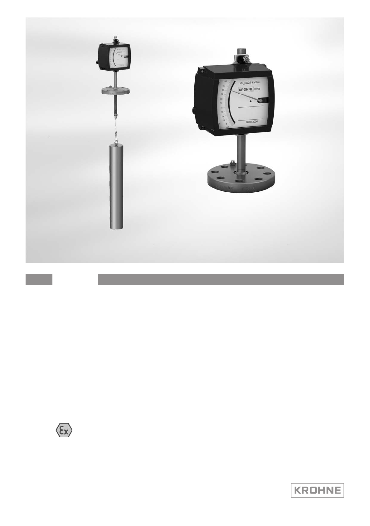
BW25
BW25
BW25BW25
Ex supplementary instructions
Equipment category II 1/2 G
Supplementary instructions Supplementary instructions
© KROHNE 03/2010 - 4000862901 MA BW25-Ex-II1/2G-AD R01 en
Page 2

CONTENTS
BW25
1 Safety instructions 3
1.1 General notes ................................................................................................................... 3
1.2 EC conformity ................................................................................................................... 3
1.3 Security information......................................................................................................... 3
2 Device description 4
2.1 Device version................................................................................................................... 4
2.2 Description code............................................................................................................... 5
2.3 Nameplate ........................................................................................................................ 6
2.4 Flammable products ........................................................................................................ 7
2.5 Device category ................................................................................................................ 7
2.6 Types of protection ........................................................................................................... 7
2.7 Ambient temperature / temperature classes.................................................................. 8
2.8 Electrical data................................................................................................................. 11
3 Installation 12
3.1 Installation...................................................................................................................... 12
3.2 Installation condititions ..................................................................................................12
3.3 Tank socket..................................................................................................................... 12
3.4 Auxiliary connections on the reference vessel .............................................................. 12
4 Electrical connections 13
4.1 General notes ................................................................................................................. 13
4.2 Electrical connection BW25/.././M9./../…/...................................................................... 13
4.3 Electrical connection BW25/.././M10.............................................................................. 14
4.4 Earthing and equipotential bonding ............................................................................... 16
5 Operation 17
5.1 Start-up........................................................................................................................... 17
5.2 Operation ........................................................................................................................ 17
5.2.1 Version BW25/.././M9./../.../ .................................................................................................. 17
5.2.2 Version BW25/.././M10 .......................................................................................................... 17
6 Service 18
6.1 Maintenance ................................................................................................................... 18
6.2 Dismantling .................................................................................................................... 20
7 Notes 21
2
www.krohne.com 03/2010 - 4000862901 MA BW25-Ex-II1/2G-AD R01 en
Page 3

BW25
1.1 General notes
These additional instructions apply to explosion-protected versions of level meters with
electrical built-ins and the marking II 1/2 G. They complete the installation and operation
instructions for the non-explosion protected versions.
The information given in these instructions contains only the data relevant to category 1/2
explosion protection. The technical details given in the installation and operation instructions for
the non-explosion protected versions apply unchanged unless excluded or superseded by these
instructions.
1.2 EC conformity
Under his sole responsibility, the manufacturer hereby declares conformity with the protection
goals of Directive 94/9/EC for use in hazardous areas.
The EC Type Examination Certificate of the Physikalisch Technische Bundesanstalt
(PTB) forms the basis of the EC Declaration of Conformity:
SAFETY INSTRUCTIONS 1
If required the EC Type Test Certificate can be downloaded under www.krohne.com.
1.3 Security information
Assembly, installation, start-up and maintenance may only be performed by personnel trained in
explosion protection!
CAUTION!
The operator respectively his agent is responsible to follow further standards, directives or laws
if required due to operating conditions or place of installation. This applies particularly for the
use of easy detachable process connections such as SMS or Clamp when measuring flammable
mediums.
PTB 05 ATEX 1053 X
PTB 05 ATEX 1053 X
PTB 05 ATEX 1053 XPTB 05 ATEX 1053 X
www.krohne.com03/2010 - 4000862901 MA BW25-Ex-II1/2G-AD R01 en
3
Page 4
2 DEVICE DESCRIPTION
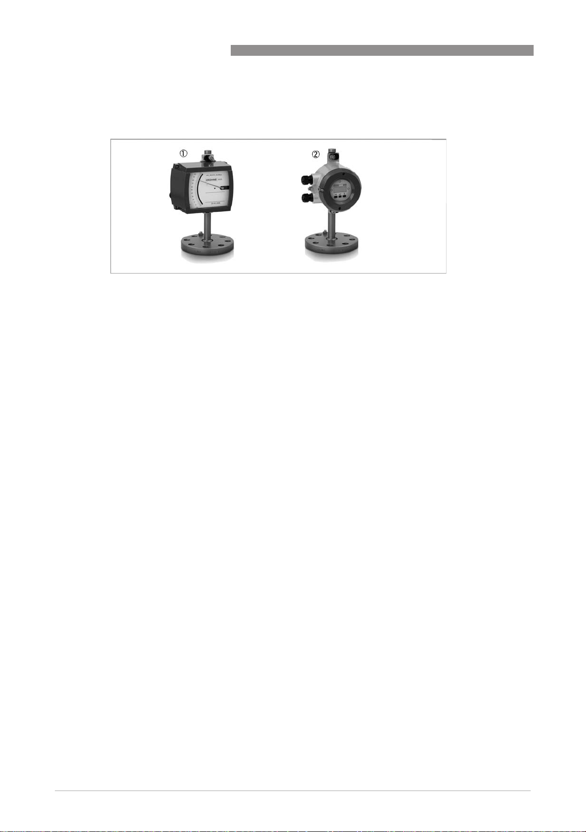
2.1 Device version
1 BW25 with indicator M9
2 BW25 with indicator M10
1 BW25/M9
• Local indicator without auxiliary power
• Max. 2 limit switches, type NAMUR, NAMUR safety-oriented
• 2-wire current output 4…20 mA, HART
®
communication
BW25
2 BW25/M10
• Ex d flameproof enclosure
• 2 digital adjustable limit switches, 2-wire open collector or type NAMUR
®
• 2-wire current output 4…20 mA, HART
communication
4
www.krohne.com 03/2010 - 4000862901 MA BW25-Ex-II1/2G-AD R01 en
Page 5

BW25
2.2 Description code
The description code* consists of the following elements:
1 Materials / versions
RR - Stainless Steel
Ti - rust-proof steel (device flange), titanium (displacement rod)
2 Version with bypass chamber
B - with bypass chamber
3 Series of indicators
M9 - Indicator M9 standard indicator
M9S - Indicator with knock-resistant sight glass
M9R - Indicator in Stainless Steel housing
M9T - Stainless steel indicator with knock-resistant sight glass
M10 - Indicator or signal converter M10
DEVICE DESCRIPTION 2
4 High temperature version
HT - Version with HT extension
5 Electrical signal output
ESK - Electronic transmitter
6 Limit switch
K1 - One limit switch
K2 - Two limit switches
* positions which are not needed are omitted (no blank positions)
www.krohne.com03/2010 - 4000862901 MA BW25-Ex-II1/2G-AD R01 en
5
Page 6
2 DEVICE DESCRIPTION
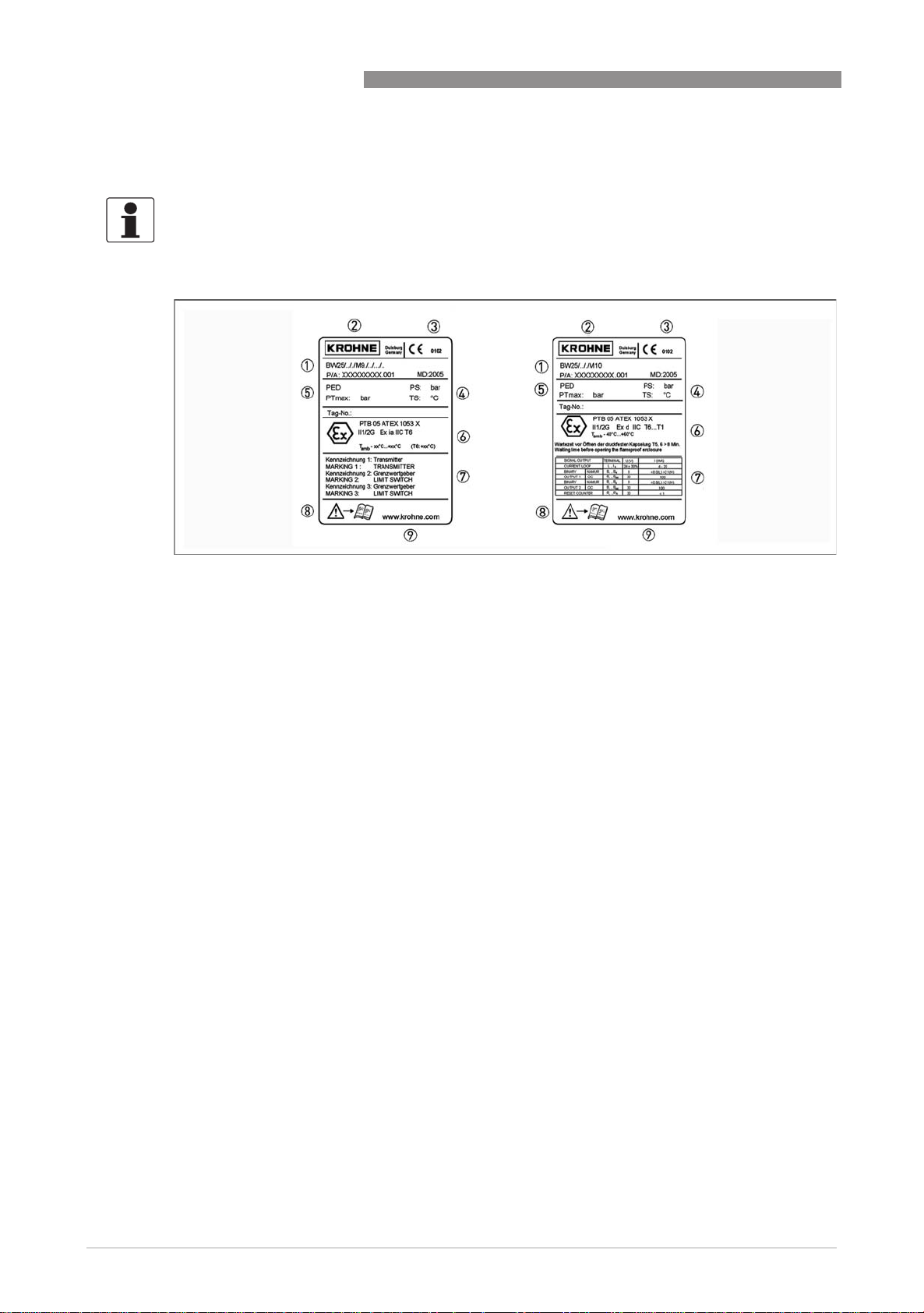
2.3 Nameplate
INFORMATION!
Before installing the device, make sure that the information on the nameplate corresponds to
the ordering data.
BW25
Figure 2-1: Nameplates on the indicator
1 Device type
2 Manufacturer
3 Notified ATEX body
4 Sizing data: temperature & pressure rating
5 PED data
6 Ex-data (respectively II 1/2G c for M9 without electrical installations)
7 Electrical connection data (are omitted for M9 without electrical installations)
8 Note manual
9 KROHNE website
Additional markings on the indicator
• SO - sales order / item
• KO - KROHNE order
• Vx - product configurator code
• AC - article code
6
www.krohne.com 03/2010 - 4000862901 MA BW25-Ex-II1/2G-AD R01 en
Page 7

BW25
2.4 Flammable products
Atmospheric conditions, flammable fluids
An explosive atmosphere is defined as a mixture of air and flammable gases, vapours, mists or
dusts under atmospheric conditions with the values
= -20...+60°C / -4...+140°F and P
T
atm
Outside of this range, no key data are available as to ignition behaviour for most mixtures. If the
application conditions do not fall within the above range, the risk of ignition in each individual
situation must be analysed on the basis of the known parameters (e.g. pressure, temperature,
process product, meter material).
2.5 Device category
The liquid level indicators are designed for Category 1/2 as per RL 94/9 EC and according to EN
60079-14 for use in Zone 0. The converters are designed for Category 2 as per RL 94/9 EC for use
in Zone 1.
= 0.8...1.1 bar.
atm
DEVICE DESCRIPTION 2
2.6 Types of protection
BW25/.././M9./.. converters without electric components are supplied as type of protection
constructional safety "c".
Electrical circuits for M9. converters with limit switches or electronic signal outputs are supplied
as intrinsically safe, category "ia" or "ib" as per EN 60079-11.
The M10 converter is supplied as protection type "explosion proof".
The marking is:
Version BW25/.././M9./.. c
Version BW25/.././M9./../.../.. Ex ia IIC T6
Version BW25/.././M10 Ex d IIC T6
The marking contains the following information:
cccc constructional safety "c"
ia
ia Intrinsically safe, level of protection "ia"
iaia
dddd flameproof enclosure
IIC
IIC Suitable for gas groups IIC, IIB and IIA
IICIIC
T6
T6 Suitable for temperature classes T6 ... T1
T6T6
www.krohne.com03/2010 - 4000862901 MA BW25-Ex-II1/2G-AD R01 en
7
Page 8

2 DEVICE DESCRIPTION
2.7 Ambient temperature / temperature classes
Due to the influence of the product temperature, level meter with built-in electrical equipment
(electric variants) are not assigned to any fixed temperature class. The temperature class of
these devices is rather a function of the product temperature and ambient temperature that is
present and the specific device version. Please see the following tables for the assignments.
The tables take into account the following parameters:
• Installed equipment
• Maximum values P
• Ambient temperature T
• Product temperature T
• Standard or high temperature version (HT)
• Heat resistance of the connecting cable
When there is more than type of built-in equipment, the data of the most unfavourable
equipment should be used.
for K1, K2, ESK
i
amb.
m
BW25
INFORMATION!
The maximum permissible product temperatures listed in the tables are valid under
the following conditions:
•
The measuring device is installed and operated in accordance with the installation
instructions.
•
It must be ensured that the flowmeter is not heated by the effects of additional
heat radiation (sunshine, neighbouring system components) and
thus operated above the permissible ambient temperature range.
•
Insulation must be limited to the piping.
Unobstructed ventilation of the indicator part must be ensured.
To do this, the variant with a projecting indicator (HT version) is preferable.
8
www.krohne.com 03/2010 - 4000862901 MA BW25-Ex-II1/2G-AD R01 en
Page 9

BW25
DEVICE DESCRIPTION 2
Maximum permissible product / flange temperature T
Device version Operation in temperature class and T
Display Installat
ion
M9
M9S
M9R
M9T
1 heat-resistant cable Tmin ≤90°C
ESK 85 97 135 1 200 1 290 1 290 1
ESK X 85 100 135 1 200 1 300 1 400 1
K. 85 100 135 1 200 1 290 1 290 1
K. X 85 100 135 1 200 1 300 1 400 1
ESK/K. 85 97 135 1 200 1 290 1 290 1
ESK/K. X 85 100 135 1 200 1 300 1 400 1
ESK 85 85 135 1 200 1 250 1 250 1
ESK X 85 100 135 1 200 1 295 1 295 1
K. 85 100 135 1 200 1 275 1 275 1
K. X 85 100 135 1 200 1 295 1 295 1
ESK/K. 85 85 135 1 200 1 250 1 250 1
ESK/K. X 85 100 135 1 200 1 295 1 295 1
HT T6 T5 T4 T3 T2 T1
T
≤40°C T
amb
[°C] BW25/.././M9./../.../..
m
amb
≤60°C
amb
Maximum permissible product / flange temperature T
Device version Operation in temperature class and T
Display Installat
ion
M9
M9S
M9R
M9T
1 heat-resistant cable Tmin ≤194°F
ESK 185 207 275 1 392 1 554 1 554 1
ESK X 185 212 275 1 392 1 572 1 752 1
K. 185 212 275 1 392 1 554 1 554 1
K. X 185 212 275 1 392 1 572 1 752 1
ESK/K. 185 207 275 1 392 1 554 1 554 1
ESK/K. X 185 212 275 1 392 1 572 1 752 1
ESK 185 185 275 1 392 1 482 1 482 1
ESK X 185 212 275 1 392 1 563 1 563 1
K. 185 212 275 1 392 1 527 1 527 1
K. X 185 212 275 1 392 1 563 1 563 1
ESK/K. 185 185 275 1 392 1 482 1 482 1
ESK/K. X 185 212 275 1 392 1 563 1 563 1
HT T6 T5 T4 T3 T2 T1
T
≤104°F T
amb
[°F] BW25/.././M9./../.../..
m
amb
≤140°F
amb
www.krohne.com03/2010 - 4000862901 MA BW25-Ex-II1/2G-AD R01 en
9
Page 10

2 DEVICE DESCRIPTION
BW25/.././M9./../…/.. minimum ambient temperatures
Indicator type Electrical module Permitted ambient temperature
BW25
Limit switch Electrical signal
[°C] °F]
output
M9. ... ESK.... -40 -40
M9 / M9R SJ3.5-SN
SJ3.5-S1N
SC3,5-N0-Y
I7S23,5-N optional -40 -40
M9S / M9T SJ3.5-SN
I7S23,5-N
optional -20 -4
optional -40 -40
Maximum permissible product / flange temperature Tm [°C] BW25/.././M9./.. without
electrical components
Display HT T
M9. 300°C 572°F
X 400°C 752°F
-40...+60°C T
amb
-40...+140°F
amb
Maximum permissible product / flange temperature Tm [°C] BW25/.././M10
T6 T5 T4 T3 T2 T1
T
-40...+60°C 85°C 100°C 135°C 1 200°C 1 300°C 1 300°C 1
amb
T
-40...+140°F 185°F 212°F 275°F 2 392°F 2 572°F 2 572°F 2
amb
1 heat-resistant cable Tmin ≤90°C
2 heat-resistant cable Tmin ≤194°F
10
www.krohne.com 03/2010 - 4000862901 MA BW25-Ex-II1/2G-AD R01 en
Page 11

BW25
2.8 Electrical data
BW25/.././M9./../
BW25/.././M9./../…/..
BW25/.././M9./../BW25/.././M9./../
The electronic signal output ESK and the limit switch may only be connected to intrinsically safe
circuits.
Maximum values shall be maintained for the isolated circuits and the following
reactances shall be taken into consideration:
/..
/../..
DEVICE DESCRIPTION 2
Circuit U
ESK2A 30 VDC 100mA 1W ≈20 nF ≈0 μH
ESK3-PA 24 VDC FISCO- Field Device
SC3,5-N0-Y.. 16 VDC 25mA 64mW 150nF 150 μH
I7S23,5-N...
SJ3.5-SN 16 VDC 25mA 64mW 30nF 100 μH
SJ3.5-S1N
BW25/.././M10
BW25/.././M10
BW25/.././M10BW25/.././M10
i
I
i
P
i
C
i
L
i
When connecting the I/O interfaces for BW25/.././M10 liquid level indicators, the following data
shall be taken into account:
Only for connection to circuits with "protected extra-low voltage (PELV)" .
For nominal values I/O function and nominal values of the non-certified slave see BW25
handbook.
www.krohne.com03/2010 - 4000862901 MA BW25-Ex-II1/2G-AD R01 en
11
Page 12

3 INSTALLATION
3.1 Installation
Installation and setup must be carried out according to the applicable installation installation
standards (e.g. EN 60079-14) by qualified personnel trained in explosion protection. The
information given in the Installation and Operation Instructions and the Supplementary
Installation and Operation Instructions must always be observed.
Install level meters so that
• There are no external forces affecting the indicator part.
• The device is accessible for any visual inspections that are necessary, and can be viewed from
all sides.
• The nameplate is clearly visible.
• It can be operated from a location with secure footing.
CAUTION!
The manufacturer is not liable for any damage resulting from improper use or use other than the
intended purpose. This applies in particular to hazards due to insufficient corrosion resistance
and suitability of the materials in contact with product.
BW25
3.2 Installation condititions
The device shall be installed such that mechanical forces from incoming flow or impact sparks in
the measuring system (e.g., from agitators) are prevented, particularly for displacement rods
made of titanium.
3.3 Tank socket
The tank socket for the meter must form a flameproof joint with the screw thread on the tank
such that the joint conforms to EN 50 018
3.4 Auxiliary connections on the reference vessel
The locking screw thread forms a flameproof joint with the reference vessel when given at least
five full turns. The screw must be removed to use the auxiliary connection. The tank must be
emptied prior to removing the locking screw!
Take appropriate measures to ensure that the auxiliary connection is flameproof. The fitting
screwed into the auxiliary connection must form a flameproof joint with the thread in the
reference vessel that conforms to DIN EN 60079-1 (note thread quality and thread length).
12
When using the auxiliary connection, the operator must ensure that no prohibited changes are
made to the process conditions (e.g. pressure, temperature, etc.).
www.krohne.com 03/2010 - 4000862901 MA BW25-Ex-II1/2G-AD R01 en
Page 13

BW25
ELECTRICAL CONNECTIONS 4
4.1 General notes
The insulation for the BW25/.././…/../…/.. liquid level indicator is rated in accordance with VDE
0110-1, in compliance with IEC 60 664-1.
Rated values for insulation:
• Overvoltage category for signal and instrument loops: II
• Pollution degree of the insulation: 2
4.2 Electrical connection BW25/.././M9./../…/
Terminal assignment
Terminal assignment
Terminal assignmentTerminal assignment
The electrical connection for the limit switch or the electronic signal output is made in the
terminal compartment of the indicator housing. Consult the handbook for terminal assignment.
Ensure that the connection conforms to the terminal polarity labelling. When the meter is
equipped with two different limit switches, the switch configuration is shown on the nameplate
and on the terminals to ensure they are assigned correctly.
Connecting cable
Connecting cable
Connecting cableConnecting cable
Connection cables for the intrinsically safe circuits must be selected to comply with the
applicable installation standard (e.g., EN 60079-14 / VDE 0165). The formation of summation
currents between the various intrinsically safe circuits shall be prevented.
Lay cables so as to ensure that there is sufficient distance between surfaces of the measuring
unit and the connecting cable.
Cable entries / Blanking plugs
Cable entries / Blanking plugs
Cable entries / Blanking plugsCable entries / Blanking plugs
The level meter comes standard with a blanking plug and a cable entry. These elements
guarantee protection from foreign bodies and water (protection type) IP65 as per EN 60529.
Consult the "Technical Data" section in the BW25 handbook for the nominal diameter range for
the cable entries.
Proper blanking plugs and seals are to be used for unused cable entries. Ensure that the seals
are tight.
www.krohne.com03/2010 - 4000862901 MA BW25-Ex-II1/2G-AD R01 en
13
Page 14

4 ELECTRICAL CONNECTIONS
4.3 Electrical connection BW25/.././M10
Terminal compartment
Terminal compartment
Terminal compartmentTerminal compartment
The cover for the electronics compartment is secured by means of a special clasp. Use an SW3
Allen key to turn the screw.
The electrical connections for the power supply and I/O functions are made in the integrated
terminal compartment of the converter. The protection type of the terminal compartment is Ex d.
Unused openings shall be closed in compliance with DIN EN 60079-1.
Cable entries and blanking plugs used shall comply with class of protection when they are ready
for operation and receive individual separate certification in accordance with DIN EN 60079-1. In
accordance with the standard IP54 is requested as minimum.
The cables can be routed into the flameproof terminal compartment in different ways:
• Direct entry of the power cables by way of flameproof cable glands in the flameproof terminal
compartment requires a separate test certificate as per DIN EN 60079-1 for flameproof
entries.
• Direct entry of the cables by way of conduits into the flameproof terminal compartment of the
device requires a flameproof joint after screwing in the conduit and a suitable stopping box in
accordance with DIN EN 60079-1.
• Direct entry of the cables by way of conduits using built-in conical thread adapters. Only
conduit with threaded ends that comply with the description on the adapter shall be inserted
into the thread adapter. The thread on the conduit must conform to the requirements of
standard DIN EN 60079-1 (min. 6 threads). A suitable stopping box shall be provided within
450 mm of the entry into the terminal compartment.
BW25
CAUTION!
Ensure that the thread adapter is firmly seated in the housing. This applies in particular after
loosening the conduits. Devices shall be electrically isolated before loosening the conduits.
Before loosening any conduit adapters, be sure to allow for any necessary waiting times before
opening the flameproof enclosure.
…
The continuous service temperature range of any components used shall be at least -40
°
(-40...+158
service temperature range must be at least -40
Connecting cable
Connecting cable
Connecting cableConnecting cable
Connecting cables shall comply with relevant installation standards (e.g., EN 60079-14 / VDE
0165). The outer diameter of the connecting wires shall conform to the cable clamping area for
the supplied cable entries.
F). For temperature ranges where a heat-resistant cable is specified, the continuous
…90°
C (-40...+194°F).
+70°C
14
www.krohne.com 03/2010 - 4000862901 MA BW25-Ex-II1/2G-AD R01 en
Page 15

BW25
ELECTRICAL CONNECTIONS 4
Connecting power and I/O functions
Connecting power and I/O functions
Connecting power and I/O functionsConnecting power and I/O functions
DANGER!
•
The converter shall be connected to the equipotential bonding conductors via the outer PA
connector
•
The wiring for the liquid level indicator's electrical connection shall be fixed.
BW25/.././M10 liquid level indicators do not require a separate power supply. The required
supply is provided via the current output.
• Before connecting or disconnecting the electrical connection cables of the device, make sure
that all cables leading to the converter are isolated from the ground of the hazardous area.
This also applies to equipotential bonding conductors (PA).
• All connecting cable conductors and shields that are not securely connected to the
equipotential grounding system of the hazardous area shall be carefully isolated from one
another and from ground (1500Vrms test voltage for non-intrinsically safe cables)
• Connect all shields by the shortest route possible to the press fitted U-clamp (PE) terminal
located in the terminal compartment. If shields are to be grounded at both ends (e.g., for EMC
reasons), adequate equipotential bonding is required between the two shields to avoid
unacceptable equalizing currents.
The converter shall be incorporated into the equipotential bonding system of the hazardous area.
Connect the conductor to the press-fitted U-clamp mounted on the outside of the converter
housing.
The meter can be incorporated into the equipotential bonding system of the hazardous area
using the U-clamp mounted on the flange if present, or suitable conductive connections (seals,
etc.)
Consult the BW25 handbook for terminal assignment.
www.krohne.com03/2010 - 4000862901 MA BW25-Ex-II1/2G-AD R01 en
15
Page 16

4 ELECTRICAL CONNECTIONS
4.4 Earthing and equipotential bonding
If the process connection does not establish an adequate electrostatic ground for the device, a
supplementary ground connection shall be established using the earth screw 1 - 2 - 3 or 4.
The position of the ground terminal is illustrated below. This bond only provides an electrostatic
connection for the device and does not fulfil the requirements for an equipotential connection.
BW25
Also ensure that the mounting screws for the indicator are firmly tightened.
16
www.krohne.com 03/2010 - 4000862901 MA BW25-Ex-II1/2G-AD R01 en
Page 17

BW25
5.1 Start-up
Make the following checks before starting up the device:
• Suitability of the materials used for the measuring unit and for the gaskets for adequate
resistance to corrosion from the process product.
• Correct connection of the built-in electrical components.
• Check that the liquid level indicator is properly mounted on the container, including any
auxiliary equipment such as the reference vessel and/or the auxiliary connections
• Check that the equipotential bonding system is connected properly (BW25/.././M10 only)
• Check that the electrostatic ground is connected properly (BW25/.././M9/../…/.. only)
• Check the correct connection of the power supply and I/O functions.
• Check that the covers of the electronic compartment are firmly in place and special locks
have been tightened down (BW25/.././M10 only).
5.2 Operation
OPERATION 5
5.2.1 Version BW25/.././M9./../.../
Adjusting the limit switch during operation is permitted. To do so, remove the housing cover.
Replace the housing cover immediately after adjusting the limit switch.
5.2.2 Version BW25/.././M10
Do not open the cover of the electronics compartment in the presence of an explosive
atmosphere.
If the device needs to be configured due to the existence of an explosive atmosphere, this can be
done using the supplied programming magnets. There is no need to open the housing as it can
be done through the glass window of the electronics compartment or digitally via the signal
output.
www.krohne.com03/2010 - 4000862901 MA BW25-Ex-II1/2G-AD R01 en
17
Page 18

6 SERVICE
6.1 Maintenance
Indicator M9
Indicator M9
Indicator M9Indicator M9
The indicator requires no maintenance under normal operating conditions and when used as
prescribed.
Within the scope of checks required to be carried out in hazardous areas to maintain systems in
proper working order, the following visual inspections should be carried out at regular intervals:
• Inspect the housing, cable entries and incoming cables for signs of corrosion or damage.
Indicator M10
Indicator M10
Indicator M10Indicator M10
The converter requires no maintenance under normal operating conditions and when used as
prescribed.
The device must be electrically isolated if it becomes necessary to open the flameproof
electronics compartment in the presence of an explosive atmosphere. For temperature classes
T6 and T5, be absolutely sure to wait until the time shown on the converter nameplate has
elapsed before opening the flameproof enclosure (8 minutes).
BW25
Before connecting or disconnecting the electrical connection cables of the device, make sure
that all cables leading to the converter are isolated from the ground of the hazardous area. This
also applies to protective ground (PE) and equipotential bonding conductors (PA).
Re-grease the flameproof cover thread of the converter and the cover seals with a suitable
resin-free grease after doing any maintenance work.
Within the scope of checks required to be carried out in hazardous areas to maintain systems
in proper working order, the following visual inspections should be carried out at regular
intervals:
• Inspect the housing, cable entries and incoming cables for signs of corrosion or damage.
18
www.krohne.com 03/2010 - 4000862901 MA BW25-Ex-II1/2G-AD R01 en
Page 19

BW25
SERVICE 6
Meter
Meter
MeterMeter
The meter requires no maintenance under normal operating conditions and when used as
prescribed.
The following visual checks should be carried out at regular intervals in conjunction with the
plant inspections required in hazardous areas to keep equipment in good operating condition:
• Check the meter and, if applicable, the reference vessel for leakage
• Include the liquid level indicator in regular pressure tests of the process vessels (only for
flammable process products).
Depending on the application, worst-case operating conditions may lead to reduced measuring
performance as a result of fouling of the measuring system. Clean the meter in accordance with
the installation and operating instructions for non-explosion proof versions of the product. The
meter must be removed for cleaning. Removing the meter will need to be coordinated with
operating conditions (e.g., check for existence of a flammable liquid or explosive atmosphere in
or at the tank or pressurized tank) and is the responsibility of the operator.
Follow the instructions for removing the entire device refer to
Dismantling
on page 20.
www.krohne.com03/2010 - 4000862901 MA BW25-Ex-II1/2G-AD R01 en
19
Page 20

6 SERVICE
6.2 Dismantling
Replacing the indicator
Replacing the indicator
Replacing the indicatorReplacing the indicator
Because of the modular design of the liquid level indicator it is possible to replace the indicator
and, if applicable, the electronic components with identical spare parts. The meter process
connections do not need to be removed. This also applies to pressurized processes.
Replacing M9 indicator
Replacing M9 indicator
Replacing M9 indicator Replacing M9 indicator
If at all possible, the meter should be electrically isolated before removing and replacing the
indicator. If this is not possible, be sure to adhere to the general conditions for intrinsically safe
circuits when removing (e.g. grounding or interconnecting any intrinsically safe circuits.)
Replacing M10 indicator
Replacing M10 indicator
Replacing M10 indicatorReplacing M10 indicator
Before disconnecting the electrical connection cables of the device, make sure that all cables
leading to the converter are isolated from the ground of the hazardous area. This also applies to
equipotential bonding conductors (PA).
BW25
The device shall be electrically isolated if it becomes necessary to open the flameproof
electronics compartment enclosure in the presence of an explosive atmosphere. For
temperature classes T6 and T5, be absolutely sure to wait until the time shown on the converter
nameplate has elapsed before opening the flameproof enclosure (8 minutes).
Exchanging the entire device
Exchanging the entire device
Exchanging the entire deviceExchanging the entire device
The same requirements described under "Replacing the indicator" apply for the indicator.
CAUTION!
Depressurize process connections prior to removing the meter.
Avoid uncontrolled discharge of residual fluid from the measuring unit.
Where environmentally critical products are concerned, carefully decontaminate the wetted
parts of the measuring tube after dismantling.
Removal and installation are the responsibility of the operator.
Maintenance
Maintenance
MaintenanceMaintenance
Maintenance work of a safety-relevant nature within the meaning of explosion protection may
only be carried out by the manufacturer, his authorised representative or under the supervision
of authorised inspectors.
20
www.krohne.com 03/2010 - 4000862901 MA BW25-Ex-II1/2G-AD R01 en
Page 21

BW25
NOTES 7
www.krohne.com03/2010 - 4000862901 MA BW25-Ex-II1/2G-AD R01 en
21
Page 22

7 NOTES
BW25
22
www.krohne.com 03/2010 - 4000862901 MA BW25-Ex-II1/2G-AD R01 en
Page 23

BW25
NOTES 7
www.krohne.com03/2010 - 4000862901 MA BW25-Ex-II1/2G-AD R01 en
23
Page 24

KROHNE product overview
• Electromagnetic flowmeters
• Variable area flowmeters
• Ultrasonic flowmeters
• Mass flowmeters
• Vortex flowmeters
• Flow controllers
• Level meters
• Temperature meters
• Pressure meters
• Analysis products
• Products and systems for the oil & gas industry
• Measuring systems for the marine industry
Head Office KROHNE Messtechnik GmbH
Ludwig-Krohne-Str. 5
47058 Duisburg (Germany)
Tel.:+49 (0)203 301 0
Fax:+49 (0)203 301 10389
info@krohne.de
© KROHNE 03/2010 - 4000862901 MA BW25-Ex-II1/2G-AD R01 en - Subject to change without notice.
The current list of all KROHNE contacts and addresses can be found at:
www.krohne.com
 Loading...