

Page 1
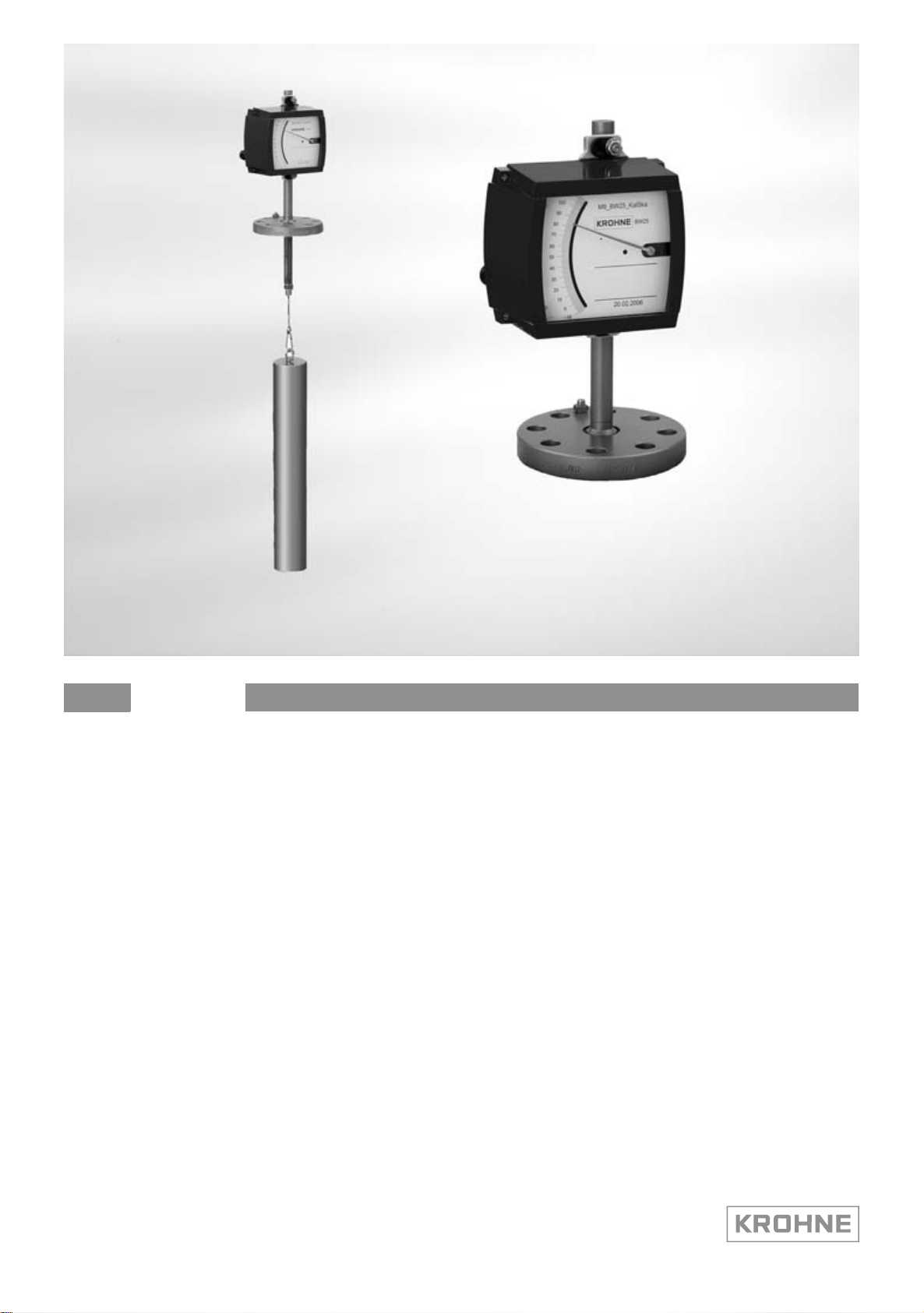
BW25
BW25
BW25BW25
Level meter
Handbook
Handbook
HandbookHandbook
© KROHNE 09/2010 - 4000432302 MA BW25 R05 en
Page 2

: IMPRINT ::::::::::::::::::::::::::::::::::
All rights reserved. It is prohibited to reproduce this documentation, or any part thereof, without
the prior written authorisation of KROHNE Messtechnik GmbH.
Subject to change without notice.
Copyright 2010 by
KROHNE Messtechnik GmbH - Ludwig-Krohne-Str. 5 - 47058 Duisburg (Germany)
2
www.krohne.com 09/2010 - 4000432302 MA BW25 R05 en
Page 3

BW25
CONTENTS
1 Safety instructions 5
1.1 Intended use ..................................................................................................................... 5
1.2 Certifications .................................................................................................................... 5
1.3 Safety instructions from the manufacturer ..................................................................... 6
1.3.1 Copyright and data protection ................................................................................................ 6
1.3.2 Disclaimer ............................................................................................................................... 6
1.3.3 Product liability and warranty ................................................................................................ 7
1.3.4 Information concerning the documentation........................................................................... 7
1.3.5 Warnings and symbols used................................................................................................... 8
1.4 Safety instructions for the operator................................................................................. 8
2 Device description 9
2.1 Scope of delivery............................................................................................................... 9
2.2 Device version................................................................................................................. 10
2.3 Nameplate ...................................................................................................................... 11
2.4 Description code............................................................................................................. 12
3 Installation 13
3.1 Notes on installation ......................................................................................................13
3.2 Storage ........................................................................................................................... 13
3.3 Installation condititions ..................................................................................................13
3.4 Installation...................................................................................................................... 14
4 Electrical connections 15
4.1 Safety instructions.......................................................................................................... 15
4.2 Electrical connection indicator M9................................................................................. 16
4.2.1 Limit switch........................................................................................................................... 16
4.2.2 Electrical signal output ESK ................................................................................................. 19
4.3 Electrical connection indicator M10............................................................................... 21
4.3.1 Electrical connection and functions ..................................................................................... 21
4.3.2 M10 Power supply - current output...................................................................................... 21
4.3.3 M10 switching outputs B1 and B2 ........................................................................................ 24
4.4 Grounding ....................................................................................................................... 26
4.5 Protection category ........................................................................................................26
5 Start-up 27
5.1 Start-up........................................................................................................................... 27
5.2 Indicator M10 .................................................................................................................. 27
www.krohne.com09/2010 - 4000432302 MA BW25 R05 en
3
Page 4

CONTENTS
BW25
6 Operation 28
6.1 Operating elements........................................................................................................ 28
6.2 Basic principles of operation.......................................................................................... 29
6.2.1 Functional description of the buttons................................................................................... 29
6.2.2 Navigation within the menu structure.................................................................................. 29
6.2.3 Changing the settings in the menu....................................................................................... 30
6.2.4 Measures in the event of faulty indications.......................................................................... 30
6.3 Overview of the most important functions and indicators............................................. 31
6.4 Error messages.............................................................................................................. 32
6.5 Menu indicator M10 ........................................................................................................ 34
6.5.1 Factory Settings .................................................................................................................... 34
6.5.2 Menu structure ..................................................................................................................... 35
6.5.3 Menu explanations................................................................................................................ 36
7 Service 39
7.1 Maintenance ................................................................................................................... 39
7.2 Spare parts availability...................................................................................................39
7.3 Availability of services .................................................................................................... 39
7.4 Returning the device to the manufacturer..................................................................... 39
7.4.1 General information.............................................................................................................. 39
7.4.2 Form (for copying) to accompany a returned device............................................................ 41
7.5 Disposal .......................................................................................................................... 41
8 Technical data 42
8.1 Operating principle......................................................................................................... 42
8.2 Technical data................................................................................................................. 43
8.3 Dimensions ..................................................................................................................... 48
9 Notes 50
4
www.krohne.com 09/2010 - 4000432302 MA BW25 R05 en
Page 5
BW25
1.1 Intended use
The level meter is suitable for measuring liquids and separation layers in liquids.
The devices are especially well suited for the measurement of:
• Liquids
• Water
• Chemicals with low corrosiveness
DANGER!
For devices used in hazardous areas, additional safety notes apply; please refer to the Ex
documentation.
WARNING!
Responsibility for the use of the measurement devices with regard to suitability, intended use
and corrosion resistance of the used materials against the measured fluid lies solely with the
operator.
The manufacturer is not liable for any damage resulting from improper use or use for other than
the intended purpose.
Do not use any abrasive or highly viscous media.
SAFETY INSTRUCTIONS 1
1.2 Certifications
CE marking
The device fulfils the statutory requirements of the following EC directives:
• Pressure Equipment Directive 97/23/EC Article 3.3
• EC directive 94/9 EC - ATEX directive
• EMC Directive 89/336/EC
as well as
• EN 61010
• EMC specification acc. to EN 61326/A1
• NAMUR recommendations NE 21 and NE 43
The manufacturer certifies successful testing of the product by applying the CE marking.
www.krohne.com09/2010 - 4000432302 MA BW25 R05 en
5
Page 6

1 SAFETY INSTRUCTIONS
1.3 Safety instructions from the manufacturer
1.3.1 Copyright and data protection
The contents of this document have been created with great care. Nevertheless, we provide no
guarantee that the contents are correct, complete or up-to-date.
The contents and works in this document are subject to copyright. Contributions from third
parties are identified as such. Reproduction, processing, dissemination and any type of use
beyond what is permitted under copyright requires written authorisation from the respective
author and/or the manufacturer.
The manufacturer tries always to observe the copyrights of others, and to draw on works created
in-house or works in the public domain.
The collection of personal data (such as names, street addresses or e-mail addresses) in the
manufacturer's documents is always on a voluntary basis whenever possible. Whenever
feasible, it is always possible to make use of the offerings and services without providing any
personal data.
BW25
We draw your attention to the fact that data transmission over the Internet (e.g. when
communicating by e-mail) may involve gaps in security. It is not possible to protect such data
completely against access by third parties.
We hereby expressly prohibit the use of the contact data published as part of our duty to publish
an imprint for the purpose of sending us any advertising or informational materials that we have
not expressly requested.
1.3.2 Disclaimer
The manufacturer will not be liable for any damage of any kind by using its product, including,
but not limited to direct, indirect, incidental, punitive and consequential damages.
This disclaimer does not apply in case the manufacturer has acted on purpose or with gross
negligence. In the event any applicable law does not allow such limitations on implied warranties
or the exclusion of limitation of certain damages, you may, if such law applies to you, not be
subject to some or all of the above disclaimer, exclusions or limitations.
Any product purchased from the manufacturer is warranted in accordance with the relevant
product documentation and our Terms and Conditions of Sale.
The manufacturer reserves the right to alter the content of its documents, including this
disclaimer in any way, at any time, for any reason, without prior notification, and will not be liable
in any way for possible consequences of such changes.
6
www.krohne.com 09/2010 - 4000432302 MA BW25 R05 en
Page 7

BW25
1.3.3 Product liability and warranty
The operator shall bear responsibility for the suitability of the device for the specific purpose.
The manufacturer accepts no liability for the consequences of misuse by the operator. Improper
installation and operation of the devices (systems) will cause the warranty to be void. The
respective "Standard Terms and Conditions" which form the basis for the sales contract shall
also apply.
1.3.4 Information concerning the documentation
To prevent any injury to the user or damage to the device it is essential that you read the
information in this document and observe applicable national standards, safety requirements
and accident prevention regulations.
If this document is not in your native language and if you have any problems understanding the
text, we advise you to contact your local office for assistance. The manufacturer can not accept
responsibility for any damage or injury caused by misunderstanding of the information in this
document.
This document is provided to help you establish operating conditions, which will permit safe and
efficient use of this device. Special considerations and precautions are also described in the
document, which appear in the form of underneath icons.
SAFETY INSTRUCTIONS 1
www.krohne.com09/2010 - 4000432302 MA BW25 R05 en
7
Page 8
1 SAFETY INSTRUCTIONS
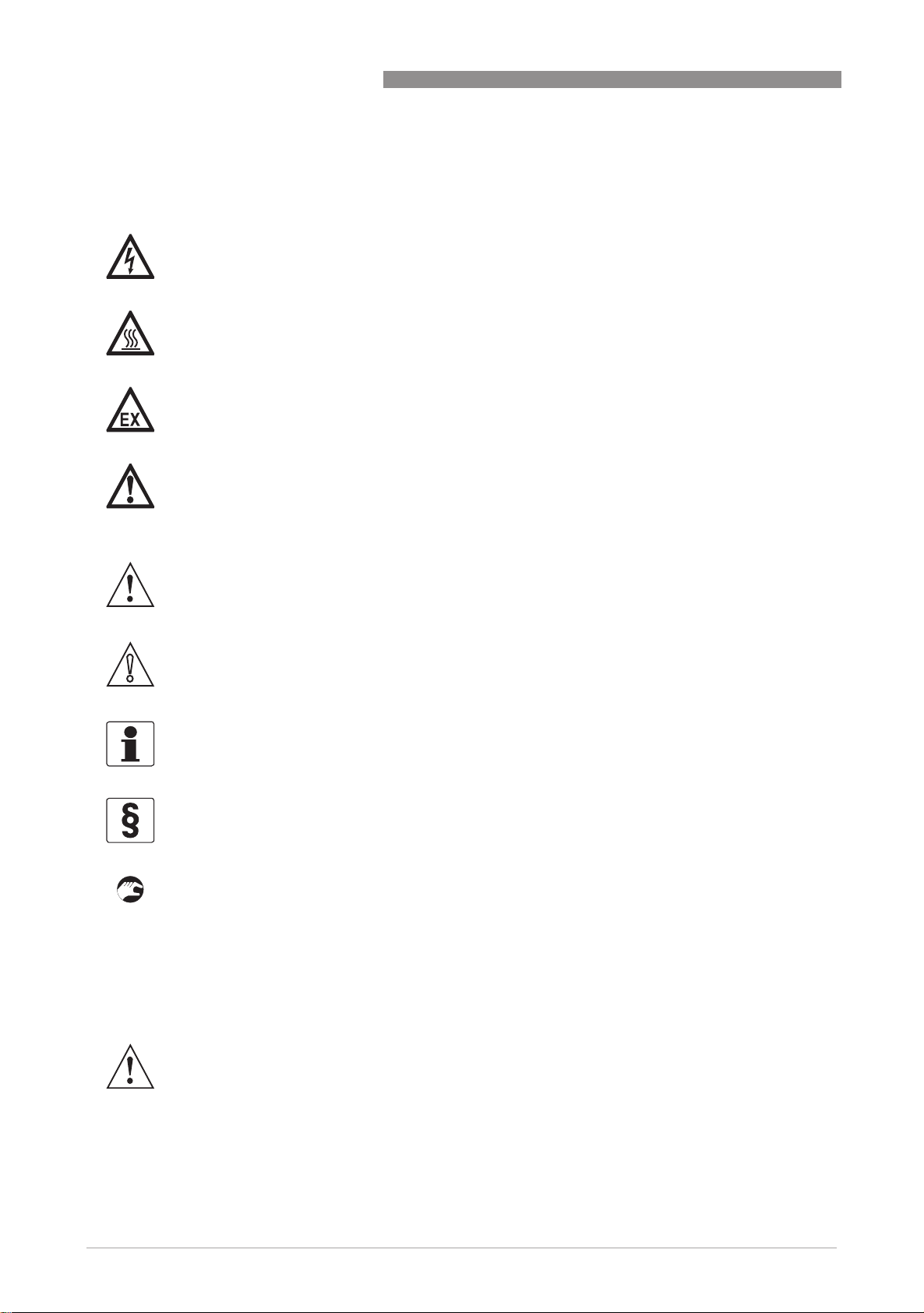
1.3.5 Warnings and symbols used
Safety warnings are indicated by the following symbols.
DANGER!
This information refers to the immediate danger when working with electricity.
DANGER!
This warning refers to the immediate danger of burns caused by heat or hot surfaces.
DANGER!
This warning refers to the immediate danger when using this device in a hazardous atmosphere.
DANGER!
These warnings must be observed without fail. Even partial disregard of this warning can lead to
serious health problems and even death. There is also the risk of seriously damaging the device
or parts of the operator's plant.
BW25
WARNING!
Disregarding this safety warning, even if only in part, poses the risk of serious health problems.
There is also the risk of damaging the device or parts of the operator's plant.
CAUTION!
Disregarding these instructions can result in damage to the device or to parts of the operator's
plant.
INFORMATION!
These instructions contain important information for the handling of the device.
LEGAL NOTICE!
This note contains information on statutory directives and standards.
• HANDLING
HANDLING
HANDLINGHANDLING
This symbol designates all instructions for actions to be carried out by the operator in the
specified sequence.
i RESULT
RESULT
RESULTRESULT
This symbol refers to all important consequences of the previous actions.
1.4 Safety instructions for the operator
WARNING!
In general, devices from the manufacturer may only be installed, commissioned, operated and
maintained by properly trained and authorized personnel.
This document is provided to help you establish operating conditions, which will permit safe and
efficient use of this device.
8
www.krohne.com 09/2010 - 4000432302 MA BW25 R05 en
Page 9
BW25
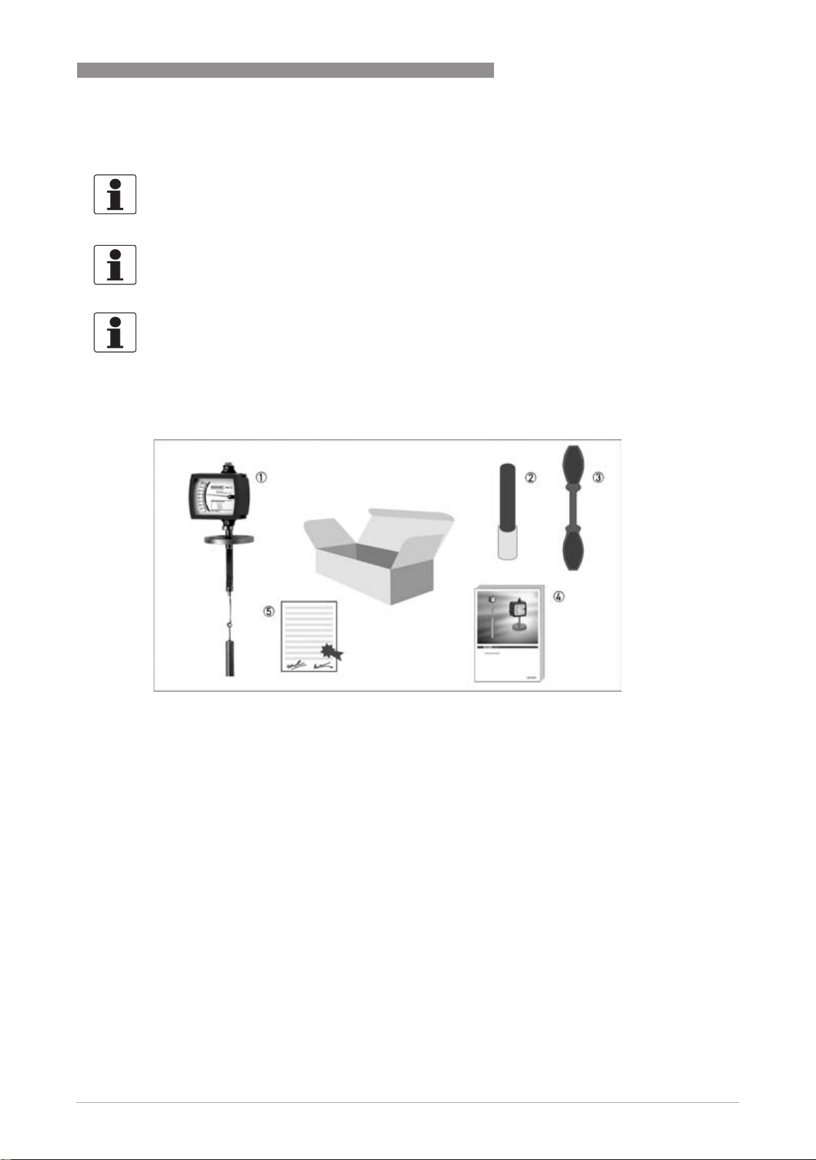
2.1 Scope of delivery
INFORMATION!
Inspect the cartons carefully for damage or signs of rough handling. Report damage to the
carrier and to the local office of the manufacturer.
INFORMATION!
Check the packing list to check if you received completely all that you ordered.
INFORMATION!
Look at the device nameplate to ensure that the device is delivered according to your order.
Check for the correct supply voltage printed on the nameplate.
DEVICE DESCRIPTION 2
1 Measuring device in ordered version
2 For indicator M10 - bar magnet
3 For indicator M10 - key
4 Handbook
5 Certificates, calibration report (supplied to order only)
www.krohne.com09/2010 - 4000432302 MA BW25 R05 en
9
Page 10

2 DEVICE DESCRIPTION
2.2 Device version
1 BW25 with indicator M9
2 BW25 with indicator M10
1 BW25/M9
• Local indicator without auxiliary power
• Max. 2 limit switches, type NAMUR, NAMUR safety-oriented
• 2-wire current output 4…20 mA, HART
®
communication
BW25
2 BW25/M10
• Ex d flameproof enclosure
• 2 digital adjustable limit switches, 2-wire open collector or type NAMUR
®
• 2-wire current output 4…20 mA, HART
communication
10
www.krohne.com 09/2010 - 4000432302 MA BW25 R05 en
Page 11
BW25
2.3 Nameplate
INFORMATION!
Look at the device nameplate to ensure that the device is delivered according to your order.
Check for the correct supply voltage printed on the nameplate.
DEVICE DESCRIPTION 2
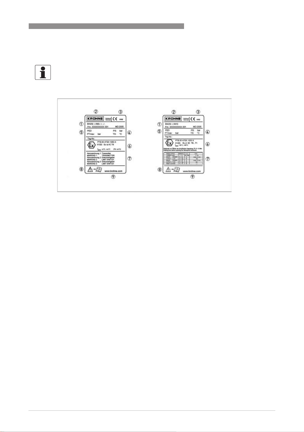
Figure 2-1: Nameplates on the indicator
1 Device type
2 Manufacturer
3 Notified ATEX body
4 Sizing data: temperature & pressure rating
5 PED data
6 Ex data
7 Electrical connection data
8 Note manual
9 KROHNE website
Additional markings on the indicator
• SO - sales order / item
• PA - order
• Vx - product configurator code
• AC - article code
www.krohne.com09/2010 - 4000432302 MA BW25 R05 en
11
Page 12

2 DEVICE DESCRIPTION
2.4 Description code
The description code* consists of the following elements:
1 Materials / versions
RR - Stainless Steel
Ti - rust-proof steel (device flange), titanium (displacement rod)
2 Version with bypass chamber
B - with bypass chamber
3 Series of indicators
M9 - Indicator M9 standard indicator
M9S - Indicator with knock-resistant sight glass
M9R - Indicator in Stainless Steel housing
M9T - Stainless steel indicator with knock-resistant sight glass
M10 - Indicator or signal converter M10
BW25
4 High temperature version
HT - Version with HT extension
5 Electrical signal output
ESK - Electronic transmitter
6 Limit switch
K1 - One limit switch
K2 - Two limit switches
* positions which are not needed are omitted (no blank positions)
12
www.krohne.com 09/2010 - 4000432302 MA BW25 R05 en
Page 13
BW25
3.1 Notes on installation
INFORMATION!
Inspect the cartons carefully for damage or signs of rough handling. Report damage to the
carrier and to the local office of the manufacturer.
INFORMATION!
Check the packing list to check if you received completely all that you ordered.
INFORMATION!
Look at the device nameplate to ensure that the device is delivered according to your order.
Check for the correct supply voltage printed on the nameplate.
3.2 Storage
• Store the device in a dry and dust-free location.
• Avoid lasting direct exposure to the sun.
• Store the device in its original packing.
• The permissible storage temperature for standard devices is -40...+80°C / -40...+176°F.
INSTALLATION 3
3.3 Installation condititions
CAUTION!
When installing the device, the following points must be observed:
•
Before installation, compare the serial number of the display (nameplate) with the serial
number on the displacement rod, the flange and the magnet.
•
In the case of level displays with a bypass chamber, the BW25 serial number on the bypass
chamber should be compared with the serial number on the display.
•
Avoid combining parts with differing serial numbers.
•
Ensure the material compatibility of the parts in contact with the product.
•
Screws, bolts and gaskets are to be provided by the customer and must be selected in
accordance with the pressure rating of the mounting flange or the operating pressure.
•
Align the gaskets. Tighten the nuts with the tightening torques of the appropriate pressure
rating.
•
Do not lay signal cables directly next to cables for the power supply.
www.krohne.com09/2010 - 4000432302 MA BW25 R05 en
13
Page 14
3 INSTALLATION
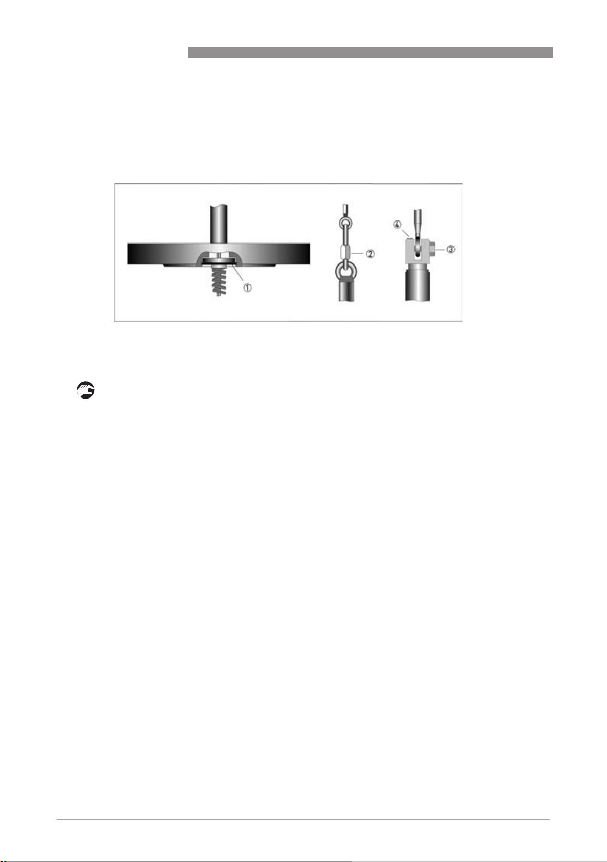
3.4 Installation
The sealing surface of the tank flange must be horizontal to ensure the perfect function of the
level measurement unit.
1 Lock ring
2 Quick-action lock
3 Retaining screw
4 Cover stop
BW25
• Insert the spring suspension pin in the flange system and secure it with a retaining ring 1.
• Install the retaining ring 1 properly and check for a correct seat all round.
• Place the seal on the tank flange.
• Suspend the displacer body on the spring suspension pin.
• Tighten the locking elements of the quick-action lock 2 (standard) or, with the variant, 3 and
4 and check for a tight fit.
• Insert the displacer element and the spring suspension pin into the tank through the tank
flange or into the preinstalled bypass chamber.
• Tighten the flange connection.
14
www.krohne.com 09/2010 - 4000432302 MA BW25 R05 en
Page 15
BW25
4.1 Safety instructions
DANGER!
All work on the electrical connections may only be carried out with the power disconnected. Take
note of the voltage data on the nameplate!
DANGER!
Observe the national regulations for electrical installations!
DANGER!
For devices used in hazardous areas, additional safety notes apply; please refer to the Ex
documentation.
WARNING!
Observe without fail the local occupational health and safety regulations. Any work done on the
electrical components of the measuring device may only be carried out by properly trained
specialists.
ELECTRICAL CONNECTIONS 4
INFORMATION!
Look at the device nameplate to ensure that the device is delivered according to your order.
Check for the correct supply voltage printed on the nameplate.
www.krohne.com09/2010 - 4000432302 MA BW25 R05 en
15
Page 16
4 ELECTRICAL CONNECTIONS
4.2 Electrical connection indicator M9
4.2.1 Limit switch
Indicator M9 can be equipped with a maximum of two electronic limit switches. The limit switch
functions with a slot sensor which is operated inductively through the semicircular metal vane
belonging to the measuring pointer. The switching points are set through the contact pointers.
The position of the contact pointer is indicated on the scale.
Limit switch module
BW25
1 Min. contact
2 Max. contact
3 Locking screw
4 Maximum pointer
5 Connection terminal
The connecting terminals have a pluggable design and can be removed in order to connect the
lines. The built-in contact types are shown on the nameplate of the indicator.
Electrical connection of the limit switches
Contact MIN MAX
Terminal no. 1 2 3 4 5 6
Connection 2-wire NAMUR - + - +
Connection 3-wire + - + -
16
www.krohne.com 09/2010 - 4000432302 MA BW25 R05 en
Page 17

BW25
ELECTRICAL CONNECTIONS 4
Limit switch connection terminals
1 2-wire limit switch NAMUR
2 3-wire limit switch
3 Terminal connection min contact
4 Terminal connection max contact
5 3-wire load
6 NAMUR isolated switching amplifier
7 3-wire power supply
Limit setting
1 Contact pointer MAX
2 Contact pointer MIN
3 Locking screw
Setting is carried out directly via contact pointers 1 and 2 :
• Slide the scale away
• Loosen the locking screw 3 slightly
• Slide the scale back to the latching point
• Set contact pointers 1 and 2 to the desired switching point
After setting has been carried out: Fix the contact pointers with the locking screw 3.
www.krohne.com09/2010 - 4000432302 MA BW25 R05 en
17
Page 18

4 ELECTRICAL CONNECTIONS
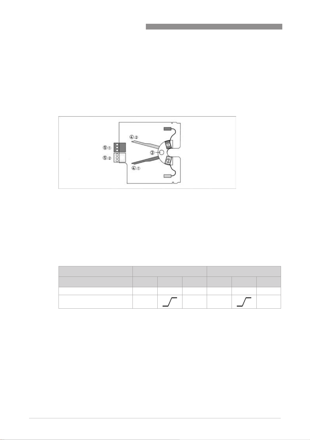
Switch contact definition
1 MIN contact
2 MAX contact
3 Pointer vane with switching vane
If the measuring pointer vane goes into the slot an alarm is triggered. If the pointer vane lies
outside the slot sensor, a wire break also causes the alarm to be triggered.
The 3-wire limit switch does not have any wire break detection
BW25
Definition MinMin - MaxMax
1 MIN 2 contact or MAX 1 contact
2 MIN 1 contact or MAX 2 contact
Current consumption in the position shown:
Contact Type Current
MIN 1 NAMUR ≤ 1 mA
MIN 2 NAMUR ≤ 1 mA
MAX 1 NAMUR ≥ 3 mA
MAX 2 NAMUR ≥ 3 mA
18
www.krohne.com 09/2010 - 4000432302 MA BW25 R05 en
Page 19

BW25
4.2.2 Electrical signal output ESK
The connecting terminals of the ESK have a pluggable design and can be removed in order to
connect the cables.
1 ESK2A current transmitter
2 Power supply 12...30VDC
3 Measurement signal 4...20 mA
4 External load, HART
®
communication
ELECTRICAL CONNECTIONS 4
The circuitry for connection to other devices such as digital evaluator units or process control
equipment must be designed with special care. In some circumstances, internal connections in
these devices (e.g. GND with PE, ground loops) may lead to impermissible voltage potentials,
which can compromise the function of the device itself or a connected device. In such cases a
protected extra-low voltage (PELV) is recommended.
1 Terminal connection
2 Converter supply isolator with electrical isolation
3 Power supply (see supply isolator information)
4 Measurement signal 4...20mA
5 External load, HART
®
communication
HART® communication
When HART® communication is carried out with the ESK, this will not in any way impair analog
measured-data transmission (4...20 mA). Exception: multidrop operation. In multidrop operation
®
a maximum of 15 devices with HART
function can be operated in parallel, whereby their analog
outputs are switched inactive. (I approx. 4 mA per device).
www.krohne.com09/2010 - 4000432302 MA BW25 R05 en
19
Page 20

4 ELECTRICAL CONNECTIONS
Power supply
INFORMATION!
The supply voltage has to be between 12 VDC and 30 VDC. This is based on the total resistance of
the measuring loop. To determine this, add up the resistances of each component in the
measuring loop (not including the level meter).
The required supply voltage can be calculated using the formula below:
.
= R
U
ext.
where
U
ext.
= the total measuring loop resistance.
R
L
INFORMATION!
The power supply has to be able to supply a minimum of 22 mA.
22 mA + 12 V
L
= the minimum supply voltage and
BW25
Load for HART® communication
INFORMATION!
®
For HART
communication a load of at least 230 ohm is required.
The maximum load resistance is calculated as follows:
DANGER!
Use a twisted two-core cable to prevent electrical interference from impeding the DC output
signal.
In some cases a shielded cable may be necessary. The cable shield may only be earthed
(grounded) at one place (on the power supply unit).
Configuration
The ESK can be configured via HART® communication. DD (Device Description) for AMS 6.x and
PDM 5.2 as well as a DTM (Device Type Manager) are available for configuration (go to download
centre at www.krohne.com).
20
With the integrated HART
values can be monitored.
®
communication, the current level can be transmitted. Two limit
www.krohne.com 09/2010 - 4000432302 MA BW25 R05 en
Page 21

BW25
4.3 Electrical connection indicator M10
4.3.1 Electrical connection and functions
The display can be removed after the housing lid has been unscrewed. The connection terminals
have a spring locking system.
Terminal connection
1 Power supply - current output
2 Switching output B1
3 Switching output B2
4 Not used for BW25
ELECTRICAL CONNECTIONS 4
4.3.2 M10 Power supply - current output
The electrical connection is reverse-polarity protected.
M10 - terminal connection I
1 Terminal connection
2 Power supply 16...32VDC
3 Measurement signal 4...20 mA
4 External load, HART
®
communication
www.krohne.com09/2010 - 4000432302 MA BW25 R05 en
21
Page 22

4 ELECTRICAL CONNECTIONS
The circuitry to other devices must be designed with especial care. In some circumstances
internal connections in these devices (e.g. GND with PE, ground loops) may lead to
impermissible voltage potentials, which can compromise the function of the device itself or a
connected device. In such cases a protected extra-low voltage (PELV) is recommended.
1 Terminal connection
2 Converter supply isolator with electrical isolation
3 Power supply (see supply isolator information)
4 Measurement signal 4...20mA
5 External load, HART
®
communication
BW25
HART® communication
When HART® communication is carried out with the M10, this will not in any way impair analogue
measured data transmission (4...20 mA).
Exception for multidrop operation. In multidrop operation, a maximum of 15 devices with
®
HART
TM function can be operated in parallel, for which the current outputs are switched to
inactive (I approx. 4 mA per device).
Power supply
INFORMATION!
The supply voltage has to be between 16 VDC and 32 VDC. This is based on the total resistance of
the measuring loop. To determine this, add up the resistances of each component in the
measuring loop (not including the level meter).
The required supply voltage can be calculated using the formula below:
.
= R
U
ext.
22 mA + 16 V
L
where
U
= the minimum supply voltage and
ext.
R
= the total measuring loop resistance.
L
22
www.krohne.com 09/2010 - 4000432302 MA BW25 R05 en
Page 23

BW25
ELECTRICAL CONNECTIONS 4
INFORMATION!
The power supply has to be able to supply a minimum of 22 mA.
Load for HART® communication
INFORMATION!
®
For HART
The maximum load resistance is calculated as follows:
DANGER!
Use a twisted two-core cable to prevent electrical interference from impeding the DC output
signal.
In some cases a shielded cable may be necessary. The cable shield may only be earthed
(grounded) at one place (on the power supply unit).
communication a load of at least 230 ohm is required.
Configuration
The electronic M10 indicator can be configured using HART® communication. DD (Device
Description) for AMS 6.x and PDM 5.2 as well as a DTM (Device Type Manager) are available for
configuration (go to download centre at www.krohne.com).
®
The current level can be transmitted using the integral HART
can be monitored.
communications. Two limit values
www.krohne.com09/2010 - 4000432302 MA BW25 R05 en
23
Page 24

4 ELECTRICAL CONNECTIONS
4.3.3 M10 switching outputs B1 and B2
The switching outputs are electrically isolated from each other and from the current output.
CAUTION!
The switching outputs can only be operating if the power supply is applied to terminals I+ and I-.
Switching outputs B1 and B2 can be electrically connected in two ways:
• NAMUR switching output - Ri approx. 1kOhm
• Low-resistance switching output with PNP technology
M10 - switching outputs
BW25
1 NAMUR terminal connection
2 Isolation switching amplifier
3 PNP technology terminal connection
4 Power supply
5 Load
Switching values
NC contact NO contact
NAMUR OC NAMUR OC
Switching value reached ≤1 mA ≤1 mA > 3mA max. 100 mA
Switching value not reached > 3mA max. 100 mA ≤1 mA ≤1 mA
24
www.krohne.com 09/2010 - 4000432302 MA BW25 R05 en
Page 25

BW25
ELECTRICAL CONNECTIONS 4
Switching capacity of B1 and B2 with PNP technology
Due to the PNP technology and the associated protective elements, there is a voltage drop Uv for
the load to be operated.
Switching capacity of B1 and B2
1 Max. switching current I [mA]
2 Minimum load impedance R
3 Power supply U
ext.
[Ohm]
L
Power loss of B1 and B2
1 Load impedance RL 100 Ohm
2 Load impedance R
3 Power loss U
4 Power supply U
d
1000 Ohm
L
ext.
www.krohne.com09/2010 - 4000432302 MA BW25 R05 en
25
Page 26

4 ELECTRICAL CONNECTIONS
4.4 Grounding
1 Grounding on the flange
2 Grounding indicator M9
3 Grounding indicator M10
DANGER!
The grounding wire may not transfer any interference voltage.
Do not use this grounding wire to ground any other electrical devices.
BW25
4.5 Protection category
The measuring device meets all requirements of protection category IP67, NEMA 4x.
DANGER!
After all servicing and maintenance work on the measuring device, the specified protection
category has to be ensured again.
Therefore it is essential to observe the following points:
• Use only original gaskets. They must be clean and free of any damage. Defective gaskets must
be replaced.
• The electrical cables used must be undamaged and must comply with regulations.
• The cables must be laid with a loop 3 upstream of the measuring device to prevent water
from getting into the housing.
• The cable feedthroughs 2 must be tightened.
• Close the unused cable feedthroughs using blanking plugs 1.
26
www.krohne.com 09/2010 - 4000432302 MA BW25 R05 en
Page 27

BW25
5.1 Start-up
CAUTION!
When starting up the device, the following points must be observed:
•
Compare the serial number on the indicator (nameplate) with the serial number on the
displacement rod, the pressure sleeve and the flange.
•
Avoid assembling components that have different serial numbers.
•
Ensure material compatibility of the wetted parts.
•
The indicator system has been factory set such that when the displacement rod is not
immersed (empty tank) the indicator shows "0" at an operating temperature of 20
•
Do not change the factory setting of the pointer. This applies in particular where high
pressures and high temperatures are involved.
5.2 Indicator M10
INFORMATION!
The device is always preset for the user and his application.
START-UP 5
°
C.
Start
After the device is switched on, the display shows the following in sequence
• "Test",
• the device type and
• the version number.
Afterwards the device performs a self-test and switches to measurement mode. Here all of the
parameters preset for the customer are analysed and checked for plausibility, and the current
measured value is displayed.
Operation
INFORMATION!
The device is low-maintenance
Comply with the application limits with regard to temperature of the medium and ambient
temperature.
www.krohne.com09/2010 - 4000432302 MA BW25 R05 en
27
Page 28

6 OPERATION
6.1 Operating elements
BW25
The device is operated with the cover on the front open, using the mechanical keys
cover closed using a bar magnet
bar magnet.
bar magnetbar magnet
keys, or with the
keyskeys
CAUTION!
The switching point of the magnetic sensors is directly under the glass disc over the appropriate
circle. Only touch the circle vertically and from the front using the bar magnet. Touching it from
the side may cause a malfunction.
Figure 6-1: Display and operating elements
1 Enter button (circuit for bar magnet)
2 Up button (circuit for bar magnet)
3 Right button (circuit for bar magnet)
4 Display
The mechanical keys and keys for the bar magnet have the same functionality. In this
documentation the keys are represented as symbols to describe the operating functions:
M10 operation keys
Button Symbol
right →
up ↑
Enter ^
28
www.krohne.com 09/2010 - 4000432302 MA BW25 R05 en
Page 29

BW25
6.2 Basic principles of operation
6.2.1 Functional description of the buttons
OPERATION 6
→
↑
^
Switch from measuring mode to menu mode
Switch to one menu level lower
Open menu item and activate change mode
In change mode:
In change mode: Move the input cursor one position to the right; after the last digit the
In change mode:In change mode:
input cursor jumps back to the beginning.
In measuring mode:
In measuring mode: Switch between measured values and error messages
In measuring mode:In measuring mode:
Change between the menu items within a menu level
In change mode:
In change mode: Changing parameters and settings; running through the available
In change mode:In change mode:
characters; shifting the decimal point to the right.
Switch to one menu level higher
Return to measuring mode with a query whether the data should be accepted
6.2.2 Navigation within the menu structure
Navigation within the menu is by means of the → and ^ buttons. Pressing button → takes you
one menu lower, ^ takes you one menu higher.
If you are already located at the lowest level (function level), you can use the button → to go the
the change mode, which can be used to set data and values.
If you are located at the first level (main menu), you can use the ^ key to exit the menu mode and
return to the measuring mode.
Measuring
mode
→ Main menu↑→ Sub-menu↑→ Function
^^^^ ^^^^ ^^^^ ^^^^
↑
→ Edit
→ ↑ ^^^^
www.krohne.com09/2010 - 4000432302 MA BW25 R05 en
29
Page 30

6 OPERATION
6.2.3 Changing the settings in the menu
Starting operation
Starting operation
Starting operationStarting operation
Operation is started using the → key
If a different key is pressed, it is necessary to wait 5 seconds before activating the → key.
If a control lockout is set, the code → → → ^ ^ ^ ↑ ↑ ↑ must be entered. If no key is pressed
within 5 seconds, code input is exited.
Exiting operator input
Exiting operator input
Exiting operator inputExiting operator input
Operation is exited by pressing the ^ key several times.
If data have been changed:
Save Yes → Changes saved.
Save No ^^^^ Changes not saved.
CAUTION!
Each time parameters or settings are changed, the measuring device carries out an internal
plausibility check.
If implausible inputs have been made, the indicator remains in the current menu, and the
changes are not accepted.
An update is carried out and the display returns to measuring mode.
The display returns to measuring mode.
BW25
Example: changing the default parameter from mmmm to cm
Display Display
Example: 5.0
1x → Fct. 1111.0
2x ↑ Fct. 3333.0
1x → Fct 3.1111
12x ↑ Fct 3.13
m
OPERATION
INSTALLATION
LANGUAGE
13
1313
END&UNIT
6.2.4 Measures in the event of faulty indications
If the indications on the display or the responses to keypad commands are faulty, you have to do
a hardware reset. Switch the power supply OFF and ON again.
cm
cmcm
1x → Fct. 3.13.1111
1x → 5.0000
6x ↑ 500
1x ^^^^ Save Yes
3x ^^^^ 500
LEVEL
m
cm
cm
30
www.krohne.com 09/2010 - 4000432302 MA BW25 R05 en
Page 31

BW25
6.3 Overview of the most important functions and indicators
INFORMATION!
A complete list of all functions and short descriptions is provided in the appendix. All default
parameters and settings are adapted for the specific customer.
Level Designation Explanation
1.4 TIME CONST. Time constant, damping value [s]
1.5.2 ERROR Error indicator
Yes: Error messages are deleted
No: error messages are suppressed.
2.1 4-20mA OUT Check current output
2.2 -
2.4
3.1 LANGUAGE Select the menu language
3.13.1 LEVEL Maximum level of the liquid
OUTPUT B Testing the switching output
The value set is represented by a 20 mA analogue current output.
If the current value exceeds the preset value, an alarm is indicated.
OPERATION 6
M10 level units
The following units are supported: m - cm - mm - inch - feet
www.krohne.com09/2010 - 4000432302 MA BW25 R05 en
31
Page 32

6 OPERATION
6.4 Error messages
Error message Description Category Remedy
BW25
NOT LINEARIZED Linearization faulty or
not activated =
measuring error
NEW LINEARI.
TABLE BAD
Faulty or non-existent
data in the
linearisation table =
measuring error
NOT
MONOTONOUS
The sequence of the
linearisation values
does not rise
monotonously.
FIRST NOT 0 % The first level value of
the linearisation table
is not 0%
LAST NOT 100 % The last level value of
the linearisation table
is not 100%
LINEARIZATIO
UNDER CONFIG
The device is in
linearization mode =
measuring error
UNIT SYSTEM
CONFLICT
The unit of the
linearisation value is
not correct for the
select level meter.
TOO FEW
ENTRIES
The linearisation
table does not have
enough support
points.
NO ZERO CAL OF AOThe analog output
zero point 4.00 mA is
not calibrated. =
Possible
measurement error
in the process control
system
NO F.SC. CAL OF AOThe current output
100% = 20.00mA is
not calibrated. =
potential measuring
error in process
control
NO TEMP.
COMPENSATION
The sensor
temperature
compensation of the
device is faulty or has
not been carried out =
possible measuring
error
OUTPUT NOT
LINEARIZED
Linearization is not
activated = measuring
error
Errors Activate linearization or carry it out again
(HART
®
communication and linearization
software are required; the original calibration
values must be known), or send the device
back to the manufacturer for linearization.
Error Check linearization or carry it out again
(HART
®
communication and linearization
software are required; the original calibration
values must be known), or send the device
back to the manufacturer for a check of the
linearization.
Error Check linearization and/or carry it out again
(HART
®
communication and linearization
software are required), or send the device
back to the manufacturer for linearization.
Error Complete the linearization and activate it
(HART
®
communication and linearization
software are required), or send the device
back to the manufacturer for linearization.
Error Correct error, carry out linearization again if
necessary (HART
®
communication and
linearization software are required), or send
the device back to the manufacturer for
linearization.
Error Carry out linearization at at least 5 points
(HART
®
communication and linearization
software are required), or send the device
back to the manufacturer for linearization.
Warning Perform calibration using ammeter and menu
3.10 or using standard HART
®
tools/process
control system and poss. external ammeter.
Caution: during calibration, switch the
measuring point to manual control.
Warning Perform calibration using ammeter and menu
item 3.11 or using standard HART
®
tools and
external ammeter if necessary. Caution:
during calibration, switch the measuring point
to manual control.
Error The device, together with an indication of the
error, must be sent back to the manufacturer
for checking.
Error Activate linearization or carry it out again
(HART
®
communication and linearization
software are required; the original calibration
values must be known), or send the device
back to the manufacturer for linearization.
32
www.krohne.com 09/2010 - 4000432302 MA BW25 R05 en
Page 33

BW25
OPERATION 6
Error message Description Category Remedy
FRAM WRITE
FAULT
ROM/FLASH
ERROR
RESTART OF
DEVICE
MULTIDROP
MODE
CRYSTAL OSC
FAULT
REF VOLTAGE
FAULT
SENSOR A FAULT
SENSOR B
FAULT
MEMORY
CORRUPTION
AO FIXED The current output is
AO SATURATED Current output
Internal
communication error
Memory error
detected during selftest.
A device restart has
taken place
The HART® multidrop
mode is activated.
The current output is
set to a fixed value of
4.5 mA.
Internal error in
device
Internal memory
error, caused by a
hardware or software
problem
set to a fixed value.
saturated
Error Check whether the display is plugged in
Error Restart the device. If the error occurs again:
Information The device has been restarted using menu
Information
Error The device must be sent back to the
Error Restart the device; if the error occurs again
Information The current output is fixed and does not
Information The current output is saturated at 20.4 or 22.0
correctly and restart the device. If the error
occurs again: send the device back to the
manufacturer with an indication of the error.
send the device back to the manufacturer with
an indication of the error.
item 1.5.2 since the last time the error
messages were reset.
The HART® multi-drop mode is activated by
selecting a polling address not equal to 0
using menu item 3.9. Polling address 0
reactivates the current output.
manufacturer with an indication of the error.
the device must be sent back to the
manufacturer with an indication of the error.
reflect the measured value. This is the case in
multidrop mode, with current output
test/calibration using the menu or HART
mA (depending on whether the alarm current
is activated or deactivated in menu item 3.12),
and is no longer coupled with the measured
value.
®
DDs ("driver") for HART
®
HART
DTMs are available at the KROHNE Download Center.
®
Tools, process control (e.g. Siemens PDM or AMS) PACTware™ and
www.krohne.com09/2010 - 4000432302 MA BW25 R05 en
33
Page 34

6 OPERATION
6.5 Menu indicator M10
6.5.1 Factory Settings
Menu Function Setting
1.1.1 Switching value B1 0.0
1.1.2 Hysteresis B1 0.0
1.2.1 Switching value B2 0.0
1.2.2 Hysteresis B2 0.0
1.3 Display Flow rate
1.4 Time constant 3 s
1.5.2 Reset error NO
3.1 Language DEUTSCH
3.2 Function B1 INACTIVE
3.3 Contact B1 NC contact
3.4 Function B2 INACTIVE
3.5 Contact B2 NC contact
3.9 Multidrop polling address 0
3.12 Alarm current OFF
3.13.1 Level meter see nameplate
3.15 Input code NO
BW25
INFORMATION!
The measuring device has been preset at the factory in accordance with the customer order.
Therefore subsequent configuration via the menu is only necessary if the intended use of the
device is changed.
34
www.krohne.com 09/2010 - 4000432302 MA BW25 R05 en
Page 35

BW25
6.5.2 Menu structure
Menu Sub-menu 1 Sub-menu 2
1111 Operation 1.2 OUTPUT B2 1.1.1 Switching value B1
2222 Test & Info 2.1 4...20 mA output
3333 Installation 3.1 Language
OPERATION 6
1.1.2 Hysteresis B1
1.2 OUTPUT B2 1.2.1 Switching value B2
1.2.2 Hysteresis B2
1.3 Display
1.4 Time constant
1.5 Reset 1.5.1 Inactive
1.5.2 Error reset
2.2 OUTPUT B1
2.3 OUTPUT B2
2.4 Inactive
2.5 Serial no.
2.6 Software Version
2.7 Tag no.
3.2 Function B1
3.3 Contact B1
3.4 Function B2
3.5 Contact B2
3.6 Inactive
3.7 Inactive
3.8 Inactive
3.9 Multidrop
3.10 Calibration 4mA
3.11 Calibration 20mA
3.12 Alarm current
3.13 Upper range value and unit 3.13.1 Level
3.13.2 Inactive
3.14 Inactive 3.14.1 Inactive
3.14.2 Inactive
3.14.3 Inactive
3.15 Input code
3.16 Basic setting
www.krohne.com09/2010 - 4000432302 MA BW25 R05 en
35
Page 36

6 OPERATION
6.5.3 Menu explanations
BW25
Level Designation Selection/input
Explanation
options
1.1.1 OUTPUT B1 INACTIVE
LEV.VALUE B1 Level value switching point. A numeric value between 0.0 ...
1.1.2 OUTPUT B1 HYST.B1 Hysteresis setting for the level value switching point. Value
100% of the level value can be set. If the current level value
exceeds this set switching point, then output B1 is
activated.
Note
Note
NoteNote
The function NC or NO can be selected using menu 3.3.
range 0…switching point. Example: If, under 1.1.1, a
switching point of 200 is set, a hysteresis value of 0...200
can be set. If a value of 0 is entered, this output has no
hysteresis. If a value of 20 is entered, the output works as
follows: If the current level value exceeds the value of 200,
the output switches. 3 If the current level value is under
the hysteresis value of 180, the switching output returns to
its normal state. 4
Note
Note
NoteNote
If this function is inverted, the output under menu 3.3 must
be set from NO 1 to NC 2 or vice versa. This function is
not activated with the counter switching point.
1.2.1 OUTPUT B2 INACTIVE
LEV.VALUE B2 See LEV.VALUE B1
1.2.2 OUTPUT B2 HYST.B2 See HYST. B1
1.3 DISPLAY LEVEL
%
LEVEL & %
1.4 TIME CONST. Setting : 1 ... 20 seconds
Note
Note
NoteNote
The settable time constant affects the current output and
the displayed current level. It thus allows attenuated
depiction when the display is not calm. If the current level
is polled via HART communication, then the transferred
measured value is dependent on the time constant.
36
www.krohne.com 09/2010 - 4000432302 MA BW25 R05 en
Page 37

BW25
OPERATION 6
1.5.1 Inactive
1.5.2 RESET ERROR YES - NO
2.1 4-20mA OUT The analogue current output can be set to fixed values in 10
2.2 OUTPUT B1 OPEN The function assignment in menu 3.2 is not taken into
CLOSED
2.3 OUTPUT B2 OPEN The function assignment in menu 3.2 is not taken into
CLOSED
2.4 Inactive
3.1 LANGUAGE ENGLISH
DEUTSCH
FRANCAIS
ITALIANO
ESPANOL
CESKY
POLSKI
NEDERLANDS
3.2 FUNCTION B1 INACTIVE Output B1 is switched off.
SWITCHING
POINT
3.3 CONTACT B1 NC contact Output B1 is normally closed. If an alarm situation occurs,
NO CONTACT Output B1 is normally open. If an alarm situation occurs,
3.4 FUNCTION B2 INACTIVE See FUNCTION B1
SWITCHING
POINT
3.5 CONTACT B2 NC contact See CONTACT B1
NO CONTACT See CONTACT B1
3.6 Inactive
3.7 Inactive
3.8 Inactive
3.9 MULTIDROP 0…15 Multi-drop mode means that the device is continuously
% increments from 4.00...20.00mA. This function has no
influence on the binary switching outputs.
Note
Note
NoteNote
This test function is switched off in multi-drop mode.
Display: "NOT AVAILABLE".
consideration here.
consideration here.
The output B1 switches at a set value depending on the
current level value.
the contact opens.
the contact closes.
See FUNCTION B1
®
working in bus mode via HART
parallel devices). The analogue current output is then fixed
to 4.1 mA. Measured values are transmitted via HART
communication (max. 15
®
communication. However, the display allows local reading
of the measured values. The polling address can be set to 1
.... 15. Larger whole numbers are not permitted. If the
polling address is set to 0, HART
The device functions as analogue. The current output of 4-
20mA is active. Standard HART
®
bus mode is switched off.
®
communication is further
guaranteed.
www.krohne.com09/2010 - 4000432302 MA BW25 R05 en
37
Page 38

6 OPERATION
BW25
3.10 4mA CALIBR. This menu item allows precise calibration of the current
3.11 20mA CALIBR. This menu item allows precise calibration of the current
3.12 ALARM
CURRENT
3.13 END & UNIT The level meter and end value can be changed.
3.13.1 LEVEL For a units list, see Section 7.4 of the manual
3.13.2 Inactive
3.14 Inactive
3.15 INP. CODE YES The input code is used to prevent authorised adjustment of
3.16 BASIC
SETTING
OFF Measured values > 100% are indicated as a current signal
ON In the event of an error the current output is set to the fixed
NO
YES This menu item can be used to select the calibrated basic
NO
output. The device generates a fixed analogue output of
4.00 mA. If the measured value differs from the one
displayed, the measured value must be entered. When the
menu is exited, the corrected value is saved.
output. The device generates a fixed analog output of 20.00
mA. If the measured value deviates from the displayed one,
then the measured value must be input. When the menu is
exited, the corrected value is saved.
up to a maximum of 22 mA.
value of 22m A.
the measurement parameters. The input code is not active
by default. If YES is selected, the last code entered must be
typed in. The default code is: → → → ^ ^ ^
↑ ↑ ↑ If, after confirmation with YES, the key → is pressed,
then a new individual, nine-digit code can be typed in. The
display shows the required key combination.
setting. This can be helpful if operating data have been
changed a number of times. This menu item cannot be
used to reset the calibration.
38
www.krohne.com 09/2010 - 4000432302 MA BW25 R05 en
Page 39

BW25
7.1 Maintenance
During routine operational maintenance of the system, the level meter should also be checked
for soiling, corrosion and mechanical wear or damage to the displacer rod, pressure sleeve and
the display.
We advise that inspections be carried out at least once per year. The device must be removed
before cleaning.
CAUTION!
Before dismantling, ensure that the tank is depressurised and vented.
In the case of devices used for measuring aggressive media, appropriate safety precautions
must be taken with regard to residual liquids on the measuring unit.
Avoid electrostatic charges when cleaning the surfaces (e.g. sight window)!
7.2 Spare parts availability
The manufacturer adheres to the basic principle that functionally adequate spare parts for each
device or each important accessory part will be kept available for a period of 3 years after
delivery of the last production run for the device.
SERVICE 7
This regulation only applies to spare parts which are subject to wear and tear under normal
operating conditions.
7.3 Availability of services
The manufacturer offers a range of services to support the customer after expiration of the
warranty. These include repair, technical support and training.
INFORMATION!
For more precise information, please contact your local representative.
7.4 Returning the device to the manufacturer
7.4.1 General information
This device has been carefully manufactured and tested. If installed and operated in accordance
with these operating instructions, it will rarely present any problems.
CAUTION!
Should you nevertheless need to return a device for inspection or repair, please pay strict
attention to the following points:
•
Due to statutory regulations on environmental protection and safeguarding the health and
safety of our personnel, manufacturer may only handle, test and repair returned devices that
have been in contact with products without risk to personnel and environment.
•
This means that the manufacturer can only service this device if it is accompanied by the
following certificate (see next section) confirming that the device is safe to handle.
www.krohne.com09/2010 - 4000432302 MA BW25 R05 en
39
Page 40

7 SERVICE
CAUTION!
If the device has been operated with toxic, caustic, flammable or water-endangering products,
you are kindly requested:
•
to check and ensure, if necessary by rinsing or neutralizing, that all cavities are free from
such dangerous substances,
•
to enclose a certificate with the device confirming that is safe to handle and stating the
product used.
BW25
40
www.krohne.com 09/2010 - 4000432302 MA BW25 R05 en
Page 41

BW25
7.4.2 Form (for copying) to accompany a returned device
Company: Address:
Department: Name:
Tel. no.: Fax no.:
Manufacturer's order no. or serial no.:
The device has been operated with the following medium:
SERVICE 7
This medium is: water-hazardous
toxic
caustic
flammable
We checked that all cavities in the device are free from such
substances.
We have flushed out and neutralized all cavities in the
device.
We hereby confirm that there is no risk to persons or the environment through any residual media
contained in the device when it is returned.
Date: Signature:
Stamp:
7.5 Disposal
CAUTION!
Disposal must be carried out in accordance with legislation applicable in your country.
www.krohne.com09/2010 - 4000432302 MA BW25 R05 en
41
Page 42

8 TECHNICAL DATA
8.1 Operating principle
The device works according to the displacement principle.
The length of the displacer rod 4 corresponds to the measuring range 2.
The displacer rod 4 suspended from a measuring spring 1 is immersed in the liquid and
detects a lifting force, which is proportional to the mass of the displaced liquid.
Each change to the rod weight corresponds to the change in the length of the spring and is thus a
measure of the filling height.
The expansion of the spring and thus the measuring stroke is transmitted to a display using a
solenoid coupling from the measuring chamber.
If the device cannot be installed from above, e.g. because there is an agitator in the tank, then
there is a special bypass chamber available for side mounting.
The lift of the proportional rod is dependent on the density of the product.
The level indication must be displayed for the liquid to be measured.
The difference in density between the tank atmosphere and liquid must be at least 100 g/l.
The atmospheric pressure and temperature must be known.
Due to the length of the spring suspension pin 3, the unmeasureable area is L = 340 mm.
BW25
42
1 Measuring spring
2 Measuring range
3 L ≥ 340mm
4 Displacer rod
www.krohne.com 09/2010 - 4000432302 MA BW25 R05 en
Page 43

BW25
8.2 Technical data
INFORMATION!
•
The following data is provided for general applications. If you require data that is more
relevant to your specific application, please contact us or your local representative.
•
Additional information (certificates, special tools, software,...) and complete product
documentation can be downloaded free of charge from the website (Download Center).
Measuring system
Application range Level measurement
Operating method / measuring principle Displacement principle
Measured value Level, separating layer
Measuring accuracy
Standard < 1.5% full scale value
Min. measuring range 0.3 m / 12"
Max. measuring range 6 m / 20 ft
Medium Liquids
Density
TECHNICAL DATA 8
≥ 0.45 kg/l / 28.1 lbs/ft
3
Materials
Housing Aluminium with artificial resin coating
Housing option Stainless steel (indicator M9)
Displacer rod Stainless steel 1.4404
Displacer rod option Titanium
Spring Stainless steel 1.4571 (T
Spring option ATS 340 (T
Flange Stainless steel 1.4404
Pressure sleeve Stainless steel 1.4404
> 100°C / 212°F)
m
< 100°C / 212°F)
m
Process connections
Max. operating pressure 40 bar - optional to 400 bar / 580 - optional 5802
Standard flange DN50 - PN40 / 2" ASME 300 lbs
Optional flange ...DN100 - ...PN400 / …4" ASME ...2.500 lbs
psig
Approvals
ATEX, indicator M9 with electrical installations Cat. II 1/2G, EEx ia IIC T6
ATEX, indicator M10 Cat. II 1/2G, EEx d IIC T6
ATEX, indicator M9 without electrical installations
for Zone 0 tanks Cat. II 1/2 Gc
for Zone 1.21 Cat. II 2 GD
for Zone 2.22 Cat. II 3 GD
www.krohne.com09/2010 - 4000432302 MA BW25 R05 en
43
Page 44

8 TECHNICAL DATA
Temperatures
Indicator M9 without electrical installations
Product or flange temperature -40…+400°C -40...+752°F
Ambient temperature T
Storage temperature -40…+60°C -40...+140°F
Indicator M9 with electrical installations
Product or flange temperature -20…+295°C -4...+563°F
Product or flange temperature, HT version -40…+400°C -40...+752°F
Ambient temperature T
Storage temperature -40…+60°C -40...+140°F
Indicator M10
Product or flange temperature -40…+200°C -40...+392°F
Ambient temperature T
Storage temperature -40…+60°C -40...+140°F
amb.
amb.
amb.
BW25
-40…+60°C -40...+140°F
-40…+60°C -40...
-40…+60°C -40...+140°F
44
www.krohne.com 09/2010 - 4000432302 MA BW25 R05 en
Page 45

BW25
TECHNICAL DATA 8
Technical data, indicator M9
M9 cable glands
Cable gland Material Cable diameter
M 16x1.5 Standard PA 3...7 mm 0.118...0.276"
M20 x 1.5 PA 8...13 mm 0.315...0.512"
M 16x1.5 Nickel-plated brass 5...9 mm 0.197...0.355"
M20 x 1.5 Nickel-plated brass 10...14 mm 0.394...0.552"
M9 limit switches
Terminal connection
Limit switch I7S23,5-N
NAMUR yes yes yes no
Connection type 2-wire 2-wire 2-wire 3-wire
Switching element
function
Nominal voltage U
Pointer vane not detected ≥ 3 mA ≥ 3 mA ≤ 1 mA ≤ 0.3 VDC
Pointer vane detected ≤ 1 mA ≤ 1 mA ≥ 3 mA UB - 3 VDC
Continuous current - - - max. 100 mA
No load current I
1 safety oriented
0
0
2
2.5 mm
SC3,5-N0
NC contact NC contact NO contact PNP NO contact
8 VDC 8 VDC 8 VDC 10...30 VDC
- - - ≤ 15 mA
SJ3,5-SN 1 SJ3,5-S1N 1 SB3,5-E2
M9 current output ESK2A
Terminal connection
Power supply 12...30 VDC
Min. power supply for HART TM 18 VDC
Measuring signal 4.00...20.00 mA = 0...100% level value in 2-wire technology
Power supply influence < 0.1%
Dependence on external resistance < 0.1%
Temperature influence < 5 uA / K
Max. external resistance / load 800 Ohm (30 VDC)
Min. load for HART TM 250 Ohm
Software firmware version 02.14
Ident No: 3210680500
2.5 mm
2
www.krohne.com09/2010 - 4000432302 MA BW25 R05 en
45
Page 46

8 TECHNICAL DATA
M9 ESK2A HART
ESK2A HART® configuration
Manufacturer name (code) KROHNE Messtechnik (69 = 45h)
Model name ESK2A (226 = E2h)
HART TM protocol revision 5.9
Device revision 1
Physical layer FSK
Device category Transmitter without galvanic isolation
M9 ESK2A process variable
ESK2A process variable, level Values [%] Signal output [mA]
Over range +102.5 (± 1%) 20.24...20.56
Device error identification > 106.25 > 21.00
Maximum 131.25 25
Multi-drop operation - 4.5
Min. U
ext.
BW25
12VDC
Technical data, indicator M10
Cable gland Standard: without
Terminal connection
Power supply 24 VDC +/- 30%
Min. power supply for HART TM 18 VDC
Measuring signal 4.00...20.00 mA = 0...100% level value in 2-wire technology
Power supply influence < 0.1 %
Dependence on external resistance < 0.1 %
Temperature influence < 5 µA/K
Max. external resistance / load ≤ 630 Ohm
Min. load for HART ≥ 250 Ohm
Software firmware version 02.14
Ident No: 3209470500
2,5mm
2
M10 HART
Manufacturer name (code) KROHNE Messtechnik (69 = 45h)
Model name M10 (234 = EA)
HART TM protocol revision 5.9
Device revision 1
Physical layer FSK
Device category Transmitter
46
www.krohne.com 09/2010 - 4000432302 MA BW25 R05 en
Page 47

BW25
TECHNICAL DATA 8
M10 process variable
Values [%] Signal output [mA]
Over range +105 (± 1%) 20.64...20.96
Device error identification > 110 > 21.60
Maximum 112.5 22
Multi-drop operation - 4.5
Min. U
ext.
M10 binary output
Two binary outputs Galvanically isolated
Operating mode Switch output NAMUR or open collector
Configurable as switch contact or pulse
NAMUR switch output
Power supply U
Signal current > 3 mA switching value not
Switch output, open collector
Power supply 8...30 VDC
Pmax 500 mW
Imax 100mA
ext.
12 VDC
output
8VDC
reached;
Open / closed or max. 10 P/s
< 1 mA switching value
reached
www.krohne.com09/2010 - 4000432302 MA BW25 R05 en
47
Page 48

8 TECHNICAL DATA
8.3 Dimensions
Dimensions with M9 indicator
Front view Side view Side view HT
BW25
HT - high temperature version
a b c d e f g h j k
[mm] 181 110 138 168 min. 340
["] 7.13 4.33 5.44 6.62 min 13.39
1 Length of the displacer rod (measuring area)
2 According to the operating conditions
1
1
≥ 20 2 106 303 185
≥ 0.79 2 4.18 11.94 7.29
48
www.krohne.com 09/2010 - 4000432302 MA BW25 R05 en
Page 49

BW25
TECHNICAL DATA 8
Dimensions M10 indicator and bypass chamber
Indicator M10 front
view
Indicator M10 side
view
Bypass
chamber.
Dimensions with M10 indicator
a b c d e f
[mm] 71 64 37 124 302 114
["] 2.8 2.5 1.5 4.9 11.9 4.5
Dimensions of bypass chamber
a b c d e f g
[mm]
["]
1 Connection according to DIN EN 1092-1
2 Length of the displacer rod (measuring area)
3 Connection according to ASME B16.5
1 1
3 3
www.krohne.com09/2010 - 4000432302 MA BW25 R05 en
340 72 115
13.4 2.8 4.5
2
2
120
4.7
49
Page 50

9 NOTES
BW25
50
www.krohne.com 09/2010 - 4000432302 MA BW25 R05 en
Page 51

BW25
NOTES 9
www.krohne.com09/2010 - 4000432302 MA BW25 R05 en
51
Page 52

KROHNE product overview
• Electromagnetic flowmeters
• Variable area flowmeters
• Ultrasonic flowmeters
• Mass flowmeters
• Vortex flowmeters
• Flow controllers
• Level meters
• Temperature meters
• Pressure meters
• Analysis products
• Measuring systems for the oil and gas industry
• Measuring systems for sea-going tankers
Head Office KROHNE Messtechnik GmbH
Ludwig-Krohne-Str. 5
D-47058 Duisburg (Germany)
Tel.:+49 (0)203 301 0
Fax:+49 (0)203 301 10389
info@krohne.de
© KROHNE 09/2010 - 4000432302 MA BW25 R05 en - Subject to change without notice.
The current list of all KROHNE contacts and addresses can be found at:
www.krohne.com
 Loading...