

Page 1
GR/PRINTO
Variable area flowmeters
Vortex flowmeters
Flow controllers
Electromagnetic flowmeters
Ultrasonic flowmeters
Mass flowmeters
Level measuring instruments
Communications engineering
Engineering systems & solutions
©
KROHNE 09/2001 7.02368.21.00
Liquid level indicator
BW 25
Status: 10/99
Page 2
152
Liquid level indicator
BW 25
Level measurement of liquids, even at high
pressures using the displacement principle
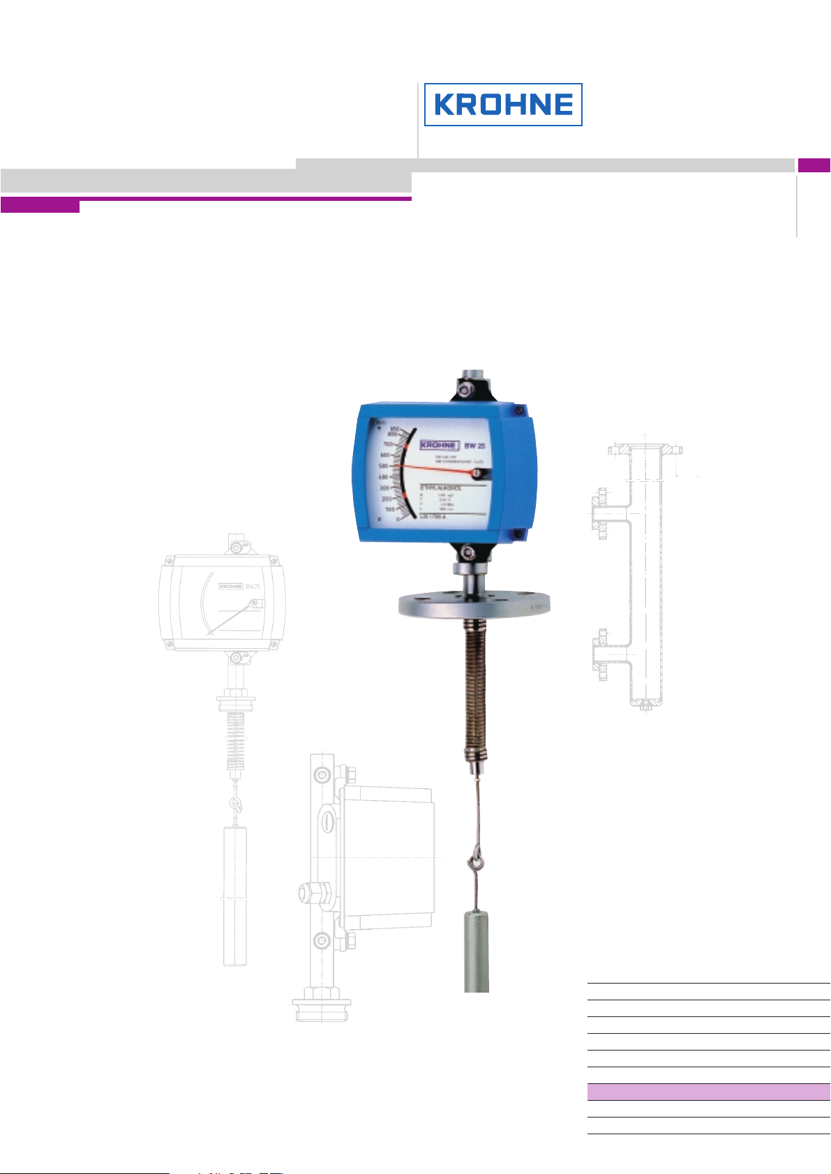
Operating principle
The BW 25 liquid level indicator operates
on the displacement principle.
The length of the displacement rod corresponds to the measuring range.
A displacement body suspended on a
measuring spring is immersed in the liquid
and is subjected to an upthrust based on
Archimedes’ principle, this being proportional
to the mass of the liquid displaced. Every
change in the weight of the rod corresponds
to a certain change in the length of the
spring, and is therefore an indication of the
liquid level. Extension of the spring is transmitted by magnetic coupling from the measuring zone to an indicator. This transmission
method permits pressure-tight separation of
the measuring spring system and the scale.
Modular assembly,
replacement or
retrofit without
interruption of the
process
Pressure-tight
separation of
measuring
and display
parts
Interface
detection
possible
Displacement rod
available 0.3 – 6 m
(1 – 20 ft)
Resistant to high
pressures ≤ 700 bar
(10000 psig) and
high temperature
≤ 400°C (752°F)
;
;
;
;
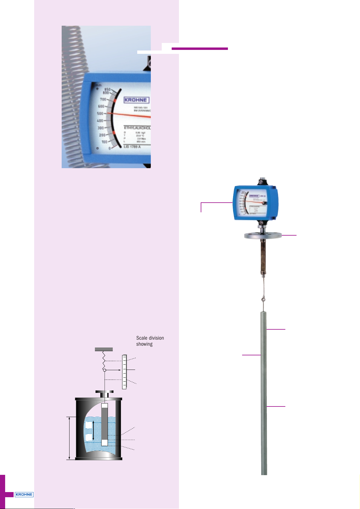
;
Scale division
showing
… full tank
… level x
… empty tank
Height setting
for
… full tank
… level x
… empty tank
Level
F
G
F
A
FA = Buoyancy
F
G
= Weight
;
;
;
;
;
Page 3

Product
Overview
Ultrasonic
Buoyancy
Capacitance
Ultrasonic RadarUltrasonic Buoyancy TDR
Continuous, non-contact
Switches
Vibration
Continuous, contact
BW 25 153
BW 25
Application range
The limit switch can be used for various materials.
This device is suitable for extreme ambient conditions.
Temperatures –60 … +400°C (–76 … +752°F)
Pressure Up to 700 bar (10 000 psig)
If the display cannot be installed from above, e.g. there is an agitator
in the container, it is possible to install it lateral with the special reference chamber.
In both cases it is important to note that the non-measurable depth
is 340 mm because of the spring mounting.
Modularity
The M9 indicator is of modular design.
This offers the following advantages:
● Electrical functions can be retrofitted
● Installation without interrupting the process
● No re-calibration necessary
● Easy and quick to replace through plug-in-technology
Product Ammonia
Pressure 450 bar (6525 psig)
Temperature 70°C (158°F)
Measuring range 1500 mm (4.9 ft)
With special versions it is possible to measure the level of the interface between two immiscible liquids of different densities. The displace rod
must be covered completely with liquid. The difference in density should be min. 100 g/l.
≤ 340 mm
Typical products are:
● Water, aqueous liquids
● Acids/alkalis
● Organic and inorganic solvents
Typical application in the chemical industry
Page 4

Technical data
Operating conditions
Product Liquids
Density ≥ 0.45 kg/l
Measuring range 0.3 – 6 m (1 – 20 ft)
Measuring accuracy ± 1.5 % of full scale range
Temperature –60 … +400°C (–76 … +752°F)
Ambient temperature ≤ 60°C (≤ 40°F)
Operating pressure
Standard 40 bar (580 psig)
Optional 700 bar (10000 psig)
Indication Linear scale markings
mm, cm, m, inch, ft, %, volume
Material
Housing Die-cast aluminium
Displacement rod
Standard Stainless steel 1.4571 (316 Ti)
Optional Titanium
Spring
Standard Stainless steel 1.4571 (316 Ti)
Optional (> 100°C /212°F) ATS 340
Flange with pressure gland Stainless steel 1.4571 (316 Ti)
Connection
Flange DIN 2501 or ANSI 16.5
Standard DN 50, PN 40
Optional DN 40/50/80/100, PN 40; DN 50, PN 64/100
1
1
/2”/ 2’’/ 3’’/ 4”, 150/300 lb
Screw G 1
1
/2’’
Others on request
Protection category (EN 60529 / IEC 529) IP 65
Electromagnetic compatibility (EMC) EN 50081-1, EN 50082-2
BW 25
154 BW 25
Responsibility for suitability and intended use of our instruments rests solely with the purchaser.
Page 5

Limit switches and electrical signal output
One or two limit switches can be built into the indicators.
Limit switches SC 3.5 N0
2-wire limit switches are connected in conformity with DIN 19234
(NAMUR). For operation, an isolation switching amplifier is required.
Technical data SC 3.5-N0
Connection 2-wire
Voltage 8 V DC
Ambient temperature –25 … +100°C (–13 … +212°F)
Protection category
to EN 60529 / IEC 529 IP 67
Self-inductance (L
i
) 150 µH
Self-capacitance (C
i
) 100 nF
Electromagnetic compatibility (EMC) EN 50081-2, EN 50082-2
Spark protection EEx ia IIC T6, EEx ib IIC T6
Approval PTB No. Ex-95.D.2195 X
Technical Data Auto cut-off
No-load voltage U
i
16 V
Short-circuit current I
i
52 mA
Output P
i
169 mW
Connection diagram
SC 3.5-N0
K1 = 1 Limit switch
K2 = 2 Limit switches
155BW 25
BW 25
Product
Overview
Ultrasonic
Buoyancy
Capacitance
Ultrasonic RadarUltrasonic Buoyancy TDR
Continuous, non-contact
Switches
Vibration
Continuous, contact
K1
K1
DC
12 3
brown black blue
K1
DC
456
brown black blue
K2
BN
BK
BU
DC
Connection diagram
ESK II- wire configuration, 4 – 20 mA
US= 12.7– 30 V
4 – 20 mA
Rext.
11+
12
–
ESK II
Limit switches SB 3.5-E2-Y
This 3-wire limit switch has a 10 – 30 V DC connection.The switching
point is visible on the scale.
3-wire limit switches (with integrated preamplifier) can be connected
directly to a PLC.
Technical data SB 3.5-E2-Y
Electrical connection 3-wire
Voltage 10 – 30 V DC
No-load power consumption ≥ 15 mA
Continuous current 100 mA
Ambient temperature –25 … +70°C
(–13 … +158°F)
Protection category
to EN 60529/IEC 529 IP 67
Electromagnetic compatibility (EMC) EN 50081-2, EN 50082-2
Display LED
Connection diagram
SB 3.5-E2-Y
Electrical signal output ESK II
The ESK II can be installed in the indicators as an option.
Given an intrinsically safe feed unit, the transmitter may also be used
in hazardous areas.
Technical data
Electrical connection 2-wire
Power supply 12.7 – 30 V DC
Current output 4 – 20 mA
Power influence < 0.1%
Load resistance dependence < 0.1%
Temperature drift ≤ 5 µA/ K
Load impedance (U-12 V)/20 mA, max. 800 Ω
Ambient temperature –25 … +85°C
Effective inner self-inductance negligible
Effective inner self-capacitance ≤ 20 nF
Protection category
to EN 60529/IEC 529 IP 20
Spark protection EEx ia IIC T6
Approval PTB No. Ex-94.C.2067
Only for connection to intrinsically safe circuits with the following
peak values:
No-load voltage U
i
30 V
Short-circuit current I
i
100 mA
Output P
i
1 W
Page 6

BW 25
156 BW 25
Reference vessel
Connection DIN 2501 or ANSI B 16.5
Flanges DN 25/50, PN 40
11/2”– 2” / Class 150/300 lb
Drain
Plug
3
/8”
Other connections on request
3
/8”
dia. 130 (dia. 5.12”)
dia. 100
30 (1.18”)
181 (7.13”)
dia. D ≥ 20 ≥ (0.79”) acc. to operating data
Dimension C = length of displacer rod (measuring range) Dimensions in mm (inches)
Dimension C = Distance between sockets (measuring range)
Flange version Screw version
110 (4.35”) 70.5 (2.78”)
138 (5.43”)
222 (8.74”)
106 (4.17”)
M16x1.5
min. 340 (min. 13.4”)
c
G 1/2 A
≥ 340 (≥ 13.39”)
340 (13.39”)C
120 (4.72”)
(dia. 3.94”)
Special flange PN 40 (300 lb/RF)
dia. 72 (dia. 2.84”)
115
(4.53”)
Page 7

157BW 25
BW 25
Product
Overview
Ultrasonic
Buoyancy
Capacitance
Ultrasonic RadarUltrasonic Buoyancy TDR
Continuous, non-contact
Switches
Vibration
Continuous, contact
Approvals
Application
With explosion protection:
In stationary storage tanks for flammable liquids of
dangerous materials classes AI, AII and B, excl.
carbon disulphide (CS2), in Zone 0.
Note: Certified devices are not standard versions! Deviations in design and technical data are possible!
Instrument version
BW 25 /... /. /.. /.. /.. – .. / Z0
Certification mark
PTB No. III B/S 1970
Type code
Instrument
BW 25 Liquid level indicator
Material (flange)
R Stainless steel 1.4571
Measuring section
N No reference vessel
B Reference vessel
Top-mounted indicator
M 9 Indicator M 9
Built-in equipment
KI.. Limit switch SC 3.5-N0 with 1–2 contacts
KD.. Limit switch SB 3.5-E2-Y with 1–2 contacts
ESK Electrical signal output
ESK/K.. Electrical signal output and 1–2 limit switches
Safety function
Ex Explosion-protected electrical equipment
Application
N Non-Ex
Z0 Flammable liquids of dangerous materials classes AI, AII and B
Options
TS Liquid/liquid interface detection
BW 25
Page 8

Notes
 Loading...