

Page 1
© KROHNE 07/2000
Operating Instructions
Supplementary
Installation and
BM70 A / P
KROHNE Messtechnik GmbH & Co. KG · Ludwig-Krohne-Str. 5 D-47058 Duisburg 1/7
Tel.: 0203-301 309 Fax: 0203-301389 · e-mail: krohne@krohne.de
Page 2

Supplementary Documentation BM 70 A, BM 70 P with PROFIBUS-PA
GENERAL .......................................................................................................................................................................3
ITEMS INCLUDED WITH SUPPLY ........................................................................................................................................3
SOFTWARE HISTORY.......................................................................................................................................................3
1. PROFIBUS-PA ............................................................................................................................................................3
1.1 GSD........................................................................................................................................................................4
1.2 PROFIBUS-PA PROFILE .........................................................................................................................................4
1.3 MEANING OF MEASUREMENT AND STATUS INFORMATION............................................................................................. 4
2. ELECTRICAL CONNECTION (SEE SECTION 7.8 IN THE INSTALLATION AND OPERATING INSTRUCTIONS)
.........................................................................................................................................................................................7
2.1 INTERCONNECTION OF DEVICES IN THE HAZARDOUS LOCATION....................................................................................7
2.2 BUS CABLE...............................................................................................................................................................7
2.3 SHIELDING AND GROUNDING......................................................................................................................................7
2.4 PROFIBUS-PA CONNECTION ..................................................................................................................................7
3. MENU SETTINGS FOR PROFIBUS-PA (SEE SECTION 8.4 IN THE INSTALLATION AND OPERATING
INSTRUCTIONS).............................................................................................................................................................8
4. TECHNICAL DATA, PROFIBUS IDENT-NO. F901.................................................................................................... 8
KROHNE Messtechnik GmbH & Co. KG · Ludwig-Krohne-Str. 5 D-47058 Duisburg 2/7
Tel.: 0203-301 309 Fax: 0203-301389 · e-mail: krohne@krohne.de
Page 3
Supplementary Documentation BM 70 A, BM 70 P with PROFIBUS-PA
General
These Instructions are supplementary to the ”Installation and Operating Instructions (Reference Manual) BM 70 A/P”
dated 5/98. The details given there, in particular the Safety Information, are valid and should be observed. These
Supplementary Instructions provide only additional information for device operation and connection to a PROFIBUSPA fieldbus.
Attention: Please set the controller to manual mode before changing parameters of the BM 70 A/P.
Items included with supply
In addition to the standard scope of supply, these Supplementary Instructions for the BM 70 A/P with PROFIBUS-PA
interface plus a diskette with all available device master files of KROHNE devices.
Software history
Issued
month/year Hardware Firmware Hardware Operating
09/98 PROFIBUS-
05/99 PROFIBUS-
Signal converter User program Instructions
Software Device User
system
1.00 05/98+Suppleme
PA Module
PA Module
3.01/990519 PC Windows
95, 98, NT
4.0
PDM ³
V4.1.1(12.9
9)
nt 09/98
05/98+Suppleme
nt 05/99, 08/99,
12/99
program
02/00 PROFIBUS-
PA
Module+Dev
ice
07/00 PROFIBUS-
PA
Module+Dev
ice
1. PROFIBUS-PA
Control system (PLC)
Class 1 master
3.03/991231 PC Windows
95, 98, NT
4.0
3.03/000622 PC Windows
95, 98, NT
4.0
Engineering or operation
control tool
Class 2 master
Analog I/O module
4-20 mA
PROFIBUS-DP, up to 12 Mbit/s
Power
Supply
Segment
coupler/link
HART device
PDM ³
V4.1.1(12.9
9)
PDM ³
V4.1.1(12.9
9)
PROFIBUS-PA
KROHNE
1 2 3 4 5 6
Segment
coupler/link
PROFIBUS-PA
KROHNE
1 2 3 4 5 6
05/98+Suppleme
nt 02/00
05/98+Suppleme
nt 07/00
kg/h
1000
kg
2
03687
900
800
H250
KROHNE
700
SN 586 677/01-03
MC H250/RR/M9/K2/ESK-Z
600
C K25.2 1.4571
F CIV 25 1.4571
MD 1997
500
C2H50H
400
D 0.93 kg/l
V 2.5 mPa.s
300
T 23.5 C
P 0.4 MPa
200
FIA 1025
100
RP
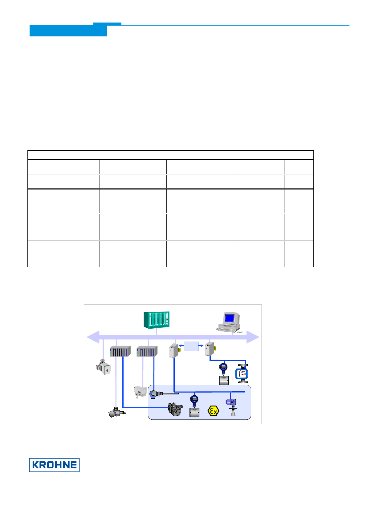
The above diagram shows a typical instrumentation with PROFIBUS-PA devices in hazardous and non-hazardous
locations, including connection of conventional devices (e.g. with 4-20mA signals) to the PROFIBUS-PA.
KROHNE Messtechnik GmbH & Co. KG · Ludwig-Krohne-Str. 5 D-47058 Duisburg 3/7
Tel.: 0203-301 309 Fax: 0203-301389 · e-mail: krohne@krohne.de
Page 4

Supplementary Documentation BM 70 A, BM 70 P with PROFIBUS-PA
The PROFIBUS-PA is normally connected to a segment coupler which, among other things, carries out the
conversion to the PROFIBUS-DP. Here, it needs to be noted in particular that the segment coupler is normally set to
a fixed baud rate on the DP side.
Further information on the planning and operation of PROFIBUS-PA networks is to be found in the KROHNE
brochure ”PROFIBUS-PA networks”.
1.1 GSD
All available GSD files of KROHNE devices – including those of the BM 70 A/P, of course - are supplied together with
each device. The GSD contains information that is needed for project planning of the PROFIBUS-DP/PA
communication network. The relevant data files must be loaded into the project planning system/master system
before start-up of the bus system.
For example, the following applies to COMET 200 or COM PROFIBUS from Siemens:
· all GSD files (*.GSD) into the directory of the GSD files, e.g. *\GSD
· all BMP files (*.BMP) into the directory of the bit maps, e.g. *\BITMAPS
In STEP7, the GSD file is automatically copied into the respective directory with “install new GSD” (in the HW-Config
Menu: EXTRAS). After that, the bit map must be copied into the directory *\SIEMENS\STEP7\S7data\Nsbmp.
Following “catalog updating” the device can be placed in the project. This will then enable the cyclic communication
(measured values and status).
1.2 PROFIBUS-PA profile
The BM 70 A/P supports the PROFIBUS-PA profile Version 2.0. Additionally, all parameters in the device are offered
via the PROFIBUS-PA interface. Within the BM 70 A/P, the following blocks are included:
· Two Function Blocks (FB) Analog Input (AI) plus Volume:
Level (default unit “m”) - Function Block AI
Distance (default unit „m“) - Function Block AI
Volume (default unit „m
Changing the unit
3
“) - as cyclic value
A change of the unit can be done only via the PROFIBUS by an operating tool. The units for level and distance
are realised according to the Profile 2.0. It can be changed via an operating tool which supports Profile 2.0.
The volume unit can be changed via the acyclic parameter in Slot 1, Index 175. Therefore an operating tool
which supports slot and index addressing is needed. Another possibility is to use the PDM tool from Siemens
because the BM 70 A/P has been integrated completely.
Volume table
The volume table is being used to calculate the volume by using the level plus a conversion table called volume
table. This volume table has to be integrated into the BM 70 A/P. The calculated volume value is available as a
cyclic value plus status. The volume table can be written to the device only by KROHNE because PROFIBUS
doesn´t support this feature at the moment.
· One transducer block for Level
This block provides the parameters defined in Profile 2.0.
· One physical block
This block contains the parameters defined in Profile 2.0, and also all device-specific parameters in the form of
an appendix.
1.3 Meaning of measurement and status information
During integration of the KROHNE device into the PROFIBUS master you can choose which values should be
transferred via PROFIBUS. This can be done by using the GSD file. Each value which is a 4 Byte Float Format
according IEEE Standard 754 Short Real Number a status byte follows. That means each measurement value
consists of 4 byte value plus 1 byte status. Other measurement values will directly follow as 5 Byte package if
configured during integration. Below the meaning of the float format and the status byte is described:
Float Format
Bit7
VZ 27 26 25 24 23 22 21 20 2-1 2-22-3 2-4 2-5 2-6 2-7 2-82-92
Exponent Mantissa Mantissa Mantissa
Example: 40 F0 00 00 (hex) = 0100 0000 1111 0000 0000 0000 0000 0000 (binary)
Byte n Byte n+1 Byte n+2 Byte n+3
Bit6
Bit7
Bit6 Bit7 Bit7
-102-112-122-132-142-152-162-172-182-192-202-212-22 2-23
KROHNE Messtechnik GmbH & Co. KG · Ludwig-Krohne-Str. 5 D-47058 Duisburg 4/7
Tel.: 0203-301 309 Fax: 0203-301389 · e-mail: krohne@krohne.de
Page 5

Supplementary Documentation BM 70 A, BM 70 P with PROFIBUS-PA
Calculation: Value = (-1)
Value = (-1)
Value = 1 * 4 * (1 + 0,5 + 0,25 + 0,125) = 7,5
VZ
0
* 2
* 2
(Exponent - 127)
(129 - 127)
* (1 + 2-1 + 2-2 + 2-3)
* (1 + Mantissa)
KROHNE Messtechnik GmbH & Co. KG · Ludwig-Krohne-Str. 5 D-47058 Duisburg 5/7
Tel.: 0203-301 309 Fax: 0203-301389 · e-mail: krohne@krohne.de
Page 6

Supplementary Documentation BM 70 A, BM 70 P with PROFIBUS-PA
Meaning of the status byte (1 Byte):
Quality Quality-Substatus Limits
Gr Gr QS QS QS QS Qu Qu
27 26 25 24 23 22 21 20
0 0 = bad
0 1 = uncertain
1 0 = good (Non Cascade)
1 1 = good (Cascade) - not supported
Status = bad
0 0 0 0 0 0 = non-specific
0 0 0 0 0 1 = configuration error
0 0 0 0 1 0 = not connected
0 0 0 0 1 1 = device failure
0 0 0 1 0 0 = sensor failure
0 0 0 1 0 1 = no communication (last usable value)
0 0 0 1 1 0 = no communication (no usable value)
0 0 0 1 1 1 = out of service
Status = uncertain
0 1 0 0 0 0 = non-specific
0 1 0 0 0 1 = last usable value
0 1 0 0 1 0 = substitute-set
0 1 0 0 1 1 = initial value
0 1 0 1 0 0 = sensor conversion not accurate
0 1 0 1 0 1 = engineering unit violation (unit not in the valid set)
0 1 0 1 1 0 = sub-normal
0 1 0 1 1 1 = configuration error
Status = good (Non-Cascade)
1 0 0 0 0 0 = ok
1 0 0 0 0 1 = active block alarm
1 0 0 0 1 0 = active advisory alarm (priority < 8)
1 0 0 0 1 1 = active critical alarm (priority > 8)
1 0 0 1 0 0 = unacknowledged block alarm
1 0 0 1 0 1 = unacknowledged advisory alarm
1 0 0 1 1 0 = unacknowledged critical alarm
1 0 1 0 0 0 = initiate fail safe
1 0 1 0 0 1 = maintenance required
Status = Limits
0 0 = ok
0 1 = low limited
1 0 = high limited
1 1 = constant
Check the first two quality bits in order to get the quality information of the measurement value:
Good (non Cascade) measurement value is ok and can be used without restrictions
Uncertain measurement value can be used but the accuracy can not be guaranteed (e.g. measurement
value has been frozen or A/D converter is saturated)
Bad measurement value is bad don´t use it
Good (Cascade) not supported because it´s not applicable for measurement devices
Diagnostics
If the device has been detected an error additional diagnostic information will be send to the master. The meaning of
the additional information is described within the GSD file under UNIT_DIAG_BIT(i).
KROHNE Messtechnik GmbH & Co. KG · Ludwig-Krohne-Str. 5 D-47058 Duisburg 6/7
Tel.: 0203-301 309 Fax: 0203-301389 · e-mail: krohne@krohne.de
Page 7

Supplementary Documentation BM 70 A, BM 70 P with PROFIBUS-PA
2. Electrical connection (see Section 7.8 in the Installation and Operating Instructions)
2.1 Interconnection of devices in the hazardous location
We recommend that a PROFIBUS-PA network in the hazardous location be projected in accordance with PTB’s
FISCO model (see KROHNE brochure ”PROFIBUS-PA networks”). The FISCO-Model may be used, if:
all electrical components which should be connected to the bus must be approved according the FISCO model (even
the termination),
the maximum cable length does not exceed 1000 m,
the values of the cable are within the following ranges R´=15...150W/km; L´=0,4...1mH/km; C´=80...200nF/km,
the approved input values of the field devices (Uo, Io, Po) are matchable with the output values of the power supply
(e.g. segmment coupler) which menas U
2.2 Bus cable
Further limitations to the cable than the FISCO limitations are not existent. Nevertheless a twisted pair and shielded
cable is strongly recommended. The good quality cable could have the following data: 44W/km, <90nF/km, <3dB
attenuation at 39kHz and 100 Ohm impedance at 31,25kHz.
2.3 Shielding and grounding
For optimum electromagnetic compatibility of systems it is extremely important that the system components, and
particularly the bus cables connecting the components, be shielded and that such shields - if possible - form an
unbroken cover, electrically speaking.
Hence it follows that, for use in non-hazardous duty systems
possible.
In “Ex“ systems an adequate equipotential bonding in the hazardous and non-hazardous location
fieldbus installation is strongly recommended. Multiple grounding of the shield is also of advantage.
Note: The use of twisted and shielded cables is strongly recommended, otherwise EMC protection of the BM 70 A/P
cannot be assured.
2.4 PROFIBUS-PA connection
Connect the bus cable as shown in the figure.
· Connect cable cores to terminals 31 and 32.
· Polarity reversal will not have any effect.
· The cable shield should be connected with minimum
length to the functional ground FE.
· The equipotential bonding conductor must be connected
to the device, if necessary via the outer U-clamp ground
terminal.
PROFIBUS-PA with current output: PROFIBUS-PA with switching output:
current-
output
I £ Uo, II £ Io und PI £ Po.
, the cable shield should be grounded as often as
FE
along the entire
32 31
bus-
connection
switching output
max. 110mA/30V
42
41
32 31
-
+
U min.
= 8V
-
4-20mA
+
Ex-i-feeder-
unit
+
U max.= 30V
KROHNE Messtechnik GmbH & Co. KG · Ludwig-Krohne-Str. 5 D-47058 Duisburg 7/7
Tel.: 0203-301 309 Fax: 0203-301389 · e-mail: krohne@krohne.de
bus-
connection
42 41
32 31
bus-
connection
Page 8

Supplementary Documentation BM 70 A, BM 70 P with PROFIBUS-PA
3. Menu settings for PROFIBUS-PA (see Section 8.4 in the Installation and Operating Instructions)
The following settings need to be made for operation of the BM 70 A/P on a PROFIBUS-PA network. Note that the
service “set slave address” is not being supported. Therefore the address can only be set by way of the local display
and operator interface.
Function (Fct.) Input range Default value Description
3.3.5 BAUDRATE Select 31250 Bd. 31250 Bd. If Fct. 3.3.7 is set to ”PROFIBUS”, the baud rate is
3.3.6 ADDRESS Input 0 ... 126
3.3.7 PROTOCOL Select HART
KROHNE/PC
PROFIBUS
126 If Fct. 3.3.7 is set to ”PROFIBUS”, the default value
PROFIBUS Selection of the communications protocol.
fixed at 31250 Bd.
of the address is 126.
Set to PROFIBUS when delivered.
(only when appropriate hardware provided)
4. Technical data, PROFIBUS Ident-No. F901
Hardware
Physical to IEC 61158-2 and the FISCO model
Bus characteristics 9... 30 V; 0.3 A max. ; 4.2 W max.
Base current 10 mA
FDE yes: separate fault disconnection electronics
provided
Fault current 6 mA; (fault current = max. continuous
current – base current)
Starting current lower than base current
”Ex” approval EEx ia IIC T6 or EEx ib IIC/IIB T6 in
conformity with the FISCO model
Connection independent of polarity
Software
GSD all KROHNE GSD files supplied on diskette
Device profile complete implementation of Profile B, V2.0
Functional blocks level [m], distance [m], in addition volume [m
Address range 0-126, default 126,
Operator control local display and operator interface at device
SAP`s 1; typically the number of service access points
as cyclic value plus status
mentioned units are default units
“set slave address” not supported
is equal to the number of class 2 masters
(operating tools)
3
]
KROHNE Messtechnik GmbH & Co. KG · Ludwig-Krohne-Str. 5 D-47058 Duisburg 8/7
Tel.: 0203-301 309 Fax: 0203-301389 · e-mail: krohne@krohne.de
 Loading...