

Page 1

Handbook
Handbook
BM 702 A
BM 702 A
BM 702 ABM 702 A
HandbookHandbook
2-wire non-contact Radar (FMCW) level meter
Software: PC-CAT 2 for Windows 5.0.0
Firmware: 7.44
© KROHNE 09/2009 - 4000643301 - MA BM 702 A R01 en
Page 2

: IMPRINT ::::::::::::::::::::::::::::::::::
All rights reserved. It is prohibited to reproduce this documentation, or any part thereof, without
the prior written authorisation of KROHNE Messtechnik GmbH & Co. KG.
Subject to change without notice.
Copyright 2009 by
KROHNE Messtechnik GmbH & Co. KG - Ludwig-Krohne-Straße 5 - 47058 Duisburg
2
www.krohne.com 09/2009 - 4000643301 - MA BM 702 A R01 en
Page 3

BM 702 A
CONTENTS
1 Safety instructions 5
1.1 Software history ............................................................................................................... 5
1.2 Intended use ..................................................................................................................... 5
1.3 Certification ...................................................................................................................... 5
1.4 European Union (EU) ........................................................................................................6
1.5 Safety instructions from the manufacturer ..................................................................... 7
1.5.1 Copyright and data protection ................................................................................................ 7
1.5.2 Disclaimer ............................................................................................................................... 7
1.5.3 Product liability and warranty ................................................................................................ 8
1.5.4 Information concerning the documentation........................................................................... 8
1.5.5 Warnings and symbols used................................................................................................... 9
1.6 Safety instructions for the operator................................................................................. 9
2 Device description 10
2.1 Scope of delivery............................................................................................................. 10
2.2 Device description .......................................................................................................... 11
2.3 Nameplates .................................................................................................................... 13
2.3.1 Non-Ex nameplate ................................................................................................................ 13
2.3.2 Ex nameplate ........................................................................................................................ 13
3 Installation 14
3.1 Notes on installation ......................................................................................................14
3.2 Storage ........................................................................................................................... 14
3.3 Transport ........................................................................................................................ 15
3.4 Pre-installation requirements ....................................................................................... 15
3.5 Theoretical data for nozzle position............................................................................... 16
3.6 Installation recommendations for liquids...................................................................... 18
3.6.1 General requirements .......................................................................................................... 18
3.6.2 Installation in stilling wells................................................................................................... 19
3.6.3 Bypass chambers.................................................................................................................. 22
3.7 How to keep false reflections to a minimum ................................................................. 24
3.8 How to install the device on the tank ............................................................................. 25
3.8.1 How to install a device with a flange connection ................................................................. 25
3.8.2 How to install a device with a threaded connection............................................................. 26
3.8.3 Field assembly ...................................................................................................................... 27
3.8.4 Antenna purging system (option for horn antenna) ............................................................. 28
4 Electrical connections 29
4.1 Safety instructions.......................................................................................................... 29
4.2 Electrical installation of output...................................................................................... 29
4.2.1 Electrical connection ............................................................................................................ 29
4.2.2 Non-Ex................................................................................................................................... 30
4.2.3 Ex i ......................................................................................................................................... 30
4.3 Protection category ........................................................................................................31
www.krohne.com09/2009 - 4000643301 - MA BM 702 A R01 en
3
Page 4

CONTENTS
BM 702 A
4.4 Networks ........................................................................................................................ 32
4.4.1 General information.............................................................................................................. 32
4.4.2 Point-to-point connection..................................................................................................... 32
4.4.3 Multi-drop networks ............................................................................................................. 33
5 Start-up 34
5.1 Start-up checklist........................................................................................................... 34
6 Operation 35
6.1 Setting parameters via program PC-CAT 2 for Windows 5.0.0 ..................................... 35
6.2 Display and operating elements (optional) .................................................................... 36
6.3 Description of status markers ....................................................................................... 37
6.4 Configuration menu (version 7.44)................................................................................. 38
6.5 Function description.......................................................................................................40
6.5.1 Tank height............................................................................................................................ 40
6.5.2 Block distance....................................................................................................................... 40
6.5.3 Scaling of the current output................................................................................................ 40
6.5.4 Empty-tank spectrum........................................................................................................... 42
6.5.5 Tank bottom tracing mode (FTB).......................................................................................... 43
6.5.6 Conversion table / volume table........................................................................................... 43
6.6 Sequence for setting parameters (example) ................................................................. 44
7 Service 45
7.1 Replacement of the signal converter............................................................................. 45
7.2 Spare parts availability...................................................................................................46
7.3 Availability of services .................................................................................................... 46
7.4 Returning the device to the manufacturer..................................................................... 46
7.4.1 General information.............................................................................................................. 46
7.4.2 Form (for copying) to accompany a returned device............................................................ 47
7.5 Disposal .......................................................................................................................... 47
8 Technical data 48
8.1 Measuring principle........................................................................................................48
8.2 Technical data................................................................................................................. 49
8.3 Pressure ratings............................................................................................................. 53
8.4 Antenna selection........................................................................................................... 54
8.5 Dimensions ..................................................................................................................... 55
9 Appendix 57
9.1 Parameter check list ...................................................................................................... 57
10 Notes 58
4
www.krohne.com 09/2009 - 4000643301 - MA BM 702 A R01 en
Page 5
BM 702 A
SAFETY INSTRUCTIONS 1
1.1 Software history
Introduction Signal converter User program Instructions
Mth./year Hardware Firmware Hardware Operating
system
Test version for field tests
12/08 BM 702 A 7.44PRE06 PC Windows
95/98/2000/
NT/XP/Vista
Series version for BM 702 A
09/09 BM 702 A 7.44 PC Windows
95/98/2000/
NT/XP/Vista
1.2 Intended use
This radar level meter measures distance, level, mass and volume of liquids, pastes and
slurries. It can be installed on tanks and reactors.
1.3 Certification
CE marking
Software Device User
program
PC-CAT 2 for
Windows
5.0.0.116
PC-CAT 2 for
Windows
5.0.0
- Online help
09/09 Online help
The device fulfils the statutory requirements of the following EC directives and
harmonized standards:
• EMC Directive 2004/108/EC: EN 61326-2-3:2006
• ATEX Directive 94/9/EC: EN 60079-0:2006, EN 60079-11:2007, EN 60079-26:2007
• R&TTE Directive 1995/5/EC: EN 302 372-2 V1.1.1
The manufacturer certifies successful testing of the product by applying the CE marking.
DANGER!
For devices used in hazardous areas, additional safety notes apply; please refer to the Ex
documentation.
www.krohne.com09/2009 - 4000643301 - MA BM 702 A R01 en
5
Page 6

1 SAFETY INSTRUCTIONS
1.4 European Union (EU)
LEGAL NOTICE!
This level transmitter is intended for installation in closed metallic tanks. It meets the
requirements of the R & TTE (Radio Equipment and Telecommunications Terminal Equipment)
Directive 1999/05/EC for use in the member countries of the EU.
The device operates using a frequency band that is not fully harmonized within the EU.
According to article 6.4 of the R&TTE Directive, the product is marked by the CE sign +
notified body number (0682) + Class 2 identifier (= alert sign).
BM 702 A
Figure 1-1: Radio approval information on the nameplate
1 CE sign
2 Notified body number (0682 = CETECOM)
3 Class 2 identifier
Refer also to the radio approval certificate on the internet site.
6
www.krohne.com 09/2009 - 4000643301 - MA BM 702 A R01 en
Page 7

BM 702 A
1.5 Safety instructions from the manufacturer
1.5.1 Copyright and data protection
The contents of this document have been created with great care. Nevertheless, we provide no
guarantee that the contents are correct, complete or up-to-date.
The contents and works in this document are subject to German copyright. Contributions from
third parties are identified as such. Reproduction, processing, dissemination and any type of use
beyond what is permitted under copyright requires written authorisation from the respective
author and/or the manufacturer.
The manufacturer tries always to observe the copyrights of others, and to draw on works created
in-house or works in the public domain.
The collection of personal data (such as names, street addresses or e-mail addresses) in the
manufacturer's documents is always on a voluntary basis whenever possible. Whenever
feasible, it is always possible to make use of the offerings and services without providing any
personal data.
SAFETY INSTRUCTIONS 1
We draw your attention to the fact that data transmission over the Internet (e.g. when
communicating by e-mail) may involve gaps in security. It is not possible to protect such data
completely against access by third parties.
We hereby expressly prohibit the use of the contact data published as part of our duty to publish
an imprint for the purpose of sending us any advertising or informational materials that we have
not expressly requested.
1.5.2 Disclaimer
The manufacturer will not be liable for any damage of any kind by using its product, including,
but not limited to direct, indirect, incidental, punitive and consequential damages.
This disclaimer does not apply in case the manufacturer has acted on purpose or with gross
negligence. In the event any applicable law does not allow such limitations on implied warranties
or the exclusion of limitation of certain damages, you may, if such law applies to you, not be
subject to some or all of the above disclaimer, exclusions or limitations.
Any product purchased from the manufacturer is warranted in accordance with the relevant
product documentation and our Terms and Conditions of Sale.
The manufacturer reserves the right to alter the content of its documents, including this
disclaimer in any way, at any time, for any reason, without prior notification, and will not be liable
in any way for possible consequences of such changes.
www.krohne.com09/2009 - 4000643301 - MA BM 702 A R01 en
7
Page 8

1 SAFETY INSTRUCTIONS
1.5.3 Product liability and warranty
The operator shall bear responsibility for the suitability of the device for the specific purpose.
The manufacturer accepts no liability for the consequences of misuse by the operator. Improper
installation and operation of the devices (systems) will cause the warranty to be void. The
respective "Standard Terms and Conditions" which form the basis for the sales contract shall
also apply.
1.5.4 Information concerning the documentation
To prevent any injury to the user or damage to the device it is essential that you read the
information in this document and observe applicable national standards, safety requirements
and accident prevention regulations.
If this document is not in your native language and if you have any problems understanding the
text, we advise you to contact your local office for assistance. The manufacturer can not accept
responsibility for any damage or injury caused by misunderstanding of the information in this
document.
This document is provided to help you establish operating conditions, which will permit safe and
efficient use of this device. Special considerations and precautions are also described in the
document, which appear in the form of underneath icons.
BM 702 A
8
www.krohne.com 09/2009 - 4000643301 - MA BM 702 A R01 en
Page 9

BM 702 A
1.5.5 Warnings and symbols used
Safety warnings are indicated by the following symbols.
DANGER!
This information refers to the immediate danger when working with electricity.
DANGER!
This warning refers to the immediate danger of burns caused by heat or hot surfaces.
DANGER!
This warning refers to the immediate danger when using this device in a hazardous atmosphere.
DANGER!
These warnings must be observed without fail. Even partial disregard of this warning can lead to
serious health problems and even death. There is also the risk of seriously damaging the device
or parts of the operator's plant.
SAFETY INSTRUCTIONS 1
WARNING!
Disregarding this safety warning, even if only in part, poses the risk of serious health problems.
There is also the risk of damaging the device or parts of the operator's plant.
CAUTION!
Disregarding these instructions can result in damage to the device or to parts of the operator's
plant.
INFORMATION!
These instructions contain important information for the handling of the device.
LEGAL NOTICE!
This note contains information on statutory directives and standards.
• HANDLING
HANDLING
HANDLINGHANDLING
This symbol designates all instructions for actions to be carried out by the operator in the
specified sequence.
i RESULT
RESULT
RESULTRESULT
This symbol refers to all important consequences of the previous actions.
1.6 Safety instructions for the operator
WARNING!
In general, devices from the manufacturer may only be installed, commissioned, operated and
maintained by properly trained and authorized personnel.
This document is provided to help you establish operating conditions, which will permit safe and
efficient use of this device.
www.krohne.com09/2009 - 4000643301 - MA BM 702 A R01 en
9
Page 10
2 DEVICE DESCRIPTION
2.1 Scope of delivery
INFORMATION!
Inspect the cartons carefully for damage or signs of rough handling. Report damage to the
carrier and to the local office of the manufacturer.
INFORMATION!
Check the packing list to check if you received completely all that you ordered.
INFORMATION!
Look at the device nameplate to ensure that the device is delivered according to your order.
Check for the correct supply voltage printed on the nameplate.
BM 702 A
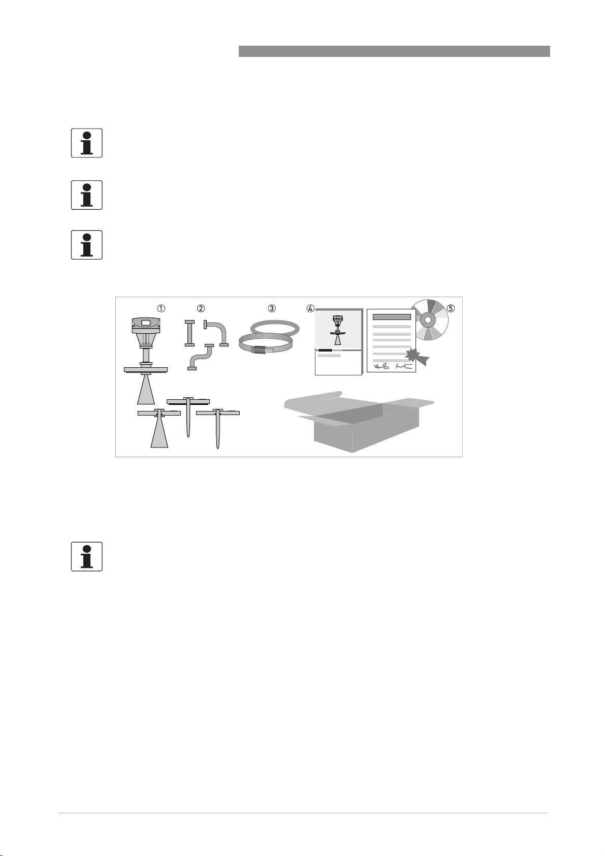
Figure 2-1: Scope of delivery
1 Signal converter and antenna as ordered
2 Antenna extensions (option)
3 Shielding material with tightening strap
4 Product documentation
5 CD-ROM (including related software)
INFORMATION!
Assembly materials and tools are not part of the delivery. Use the assembly materials and tools
in compliance with the applicable occupational health and safety directives.
10
www.krohne.com 09/2009 - 4000643301 - MA BM 702 A R01 en
Page 11
BM 702 A
2.2 Device description
Most of the device versions are delivered in fully assembled condition. The modular design
allows maximum flexibility.
The system consists of:
• Converter
• Flange
• Antenna (Wave-Stick or horn antenna)
DEVICE DESCRIPTION 2
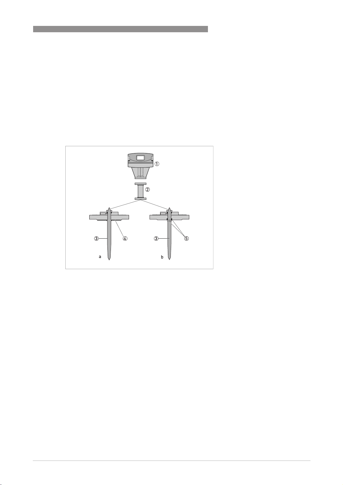
Figure 2-2: Versions with Wave-Stick
a = Wave-Stick with plate (PTFE)
b = Wave-Stick without plate (PP or PTFE)
1 Converter
2 High-temperature distance piece (option)
3 Wave-Stick
4 Flange plate
5 Gasket
www.krohne.com09/2009 - 4000643301 - MA BM 702 A R01 en
11
Page 12
2 DEVICE DESCRIPTION
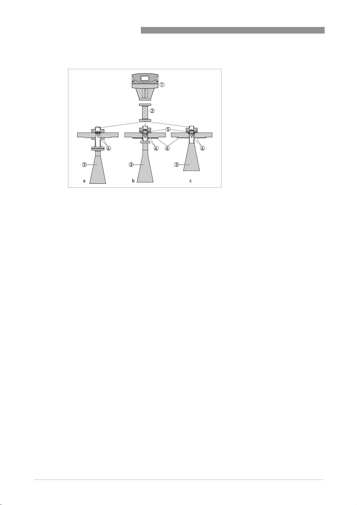
Figure 2-3: Versions with horn antenna
a = horn antenna with LP flange system
b = horn antenna with V96 flange system (Hastelloy
c = horn antenna with V96 flange system (Titanium or Tantalum flange plate)
®
flange plate)
BM 702 A
1 Converter
2 High-temperature distance piece (option)
3 Horn antenna
4 Gasket
5 Separation (Metaglass
6 Flange plate
®
)
12
www.krohne.com 09/2009 - 4000643301 - MA BM 702 A R01 en
Page 13
BM 702 A
2.3 Nameplates
INFORMATION!
Look at the device nameplate to ensure that the device is delivered according to your order.
Check for the correct supply voltage printed on the nameplate.
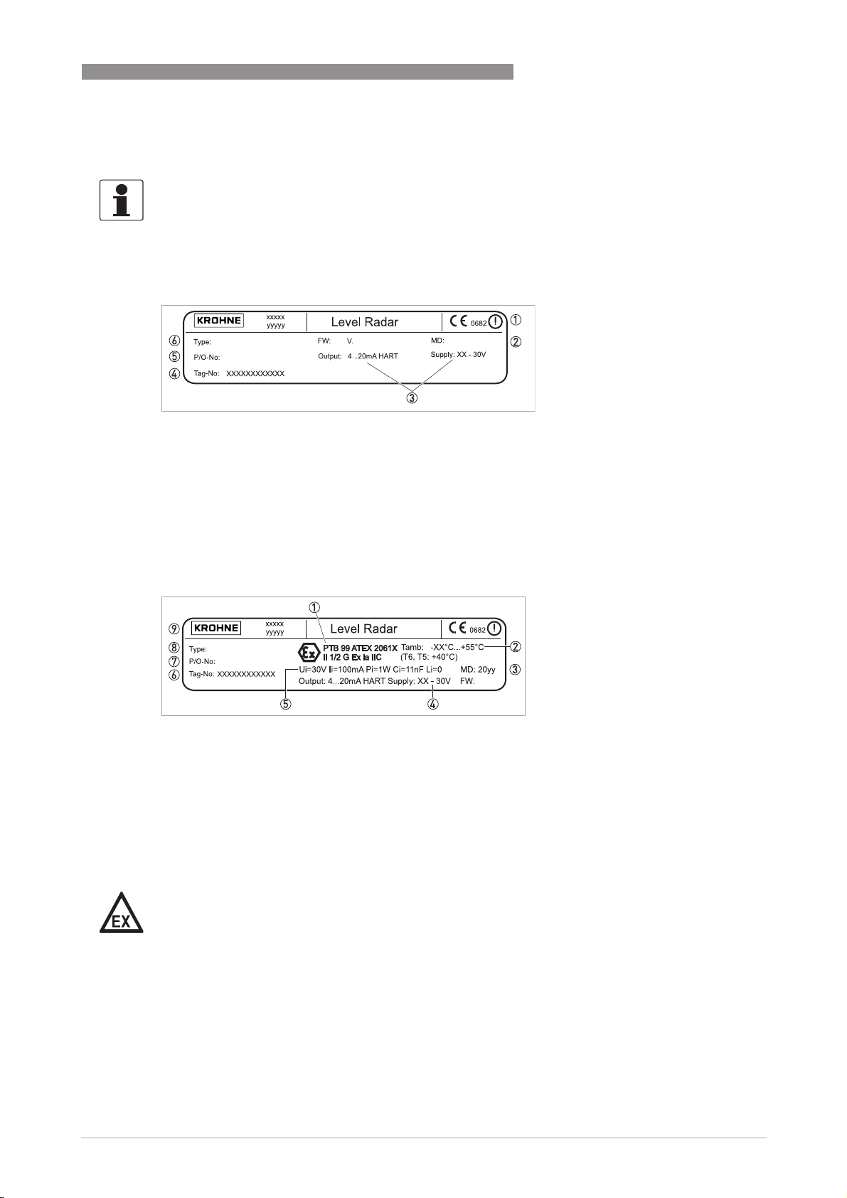
2.3.1 Non-Ex nameplate
Figure 2-4: Non-Ex nameplate
1 Notified body for radio approval.
2 Date of manufacture
3 Electrical data: supply voltage and output
4 Customer tag number
5 Production order number
6 Model name and number
DEVICE DESCRIPTION 2
2.3.2 Ex nameplate
Figure 2-5: Non-Ex nameplate
1 ATEX certifcation agency code and equipment approval categories
2 Ambient temperature and temperature classes
3 Date of manufacture
4 Electrical data: supply voltage and output
5 Intrinsically-safe circuit data
6 Customer tag number
7 Production order number
8 Model name and number
9 Company logo and information
DANGER!
For devices used in hazardous areas, additional safety notes apply; please refer to the Ex
documentation.
www.krohne.com09/2009 - 4000643301 - MA BM 702 A R01 en
13
Page 14
3 INSTALLATION
3.1 Notes on installation
INFORMATION!
Inspect the cartons carefully for damage or signs of rough handling. Report damage to the
carrier and to the local office of the manufacturer.
INFORMATION!
Check the packing list to check if you received completely all that you ordered.
INFORMATION!
Look at the device nameplate to ensure that the device is delivered according to your order.
Check for the correct supply voltage printed on the nameplate.
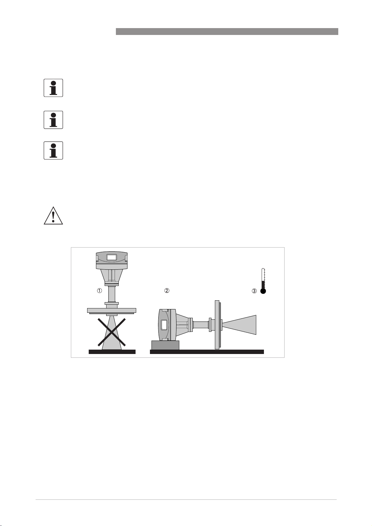
3.2 Storage
WARNING!
Do not keep the device in a vertical position. This will damage the antenna and the device will not
measure correctly.
BM 702 A
14
Figure 3-1: Storage conditions
1 When you put the device into storage, do not keep it in a vertical position.
2 Put the device on its side. We recommend that you use the packing in which it was delivered.
3 Storage temperature range: -40...+85°C / -40...+185°F
• Store the device in a dry and dust-free location.
• Keep the converter out of the sunlight.
• Store the device in its original packing.
www.krohne.com 09/2009 - 4000643301 - MA BM 702 A R01 en
Page 15

BM 702 A
3.3 Transport
WARNING!
•
Depending on the version, the device will weight approx. 5...30 kg / 11...66 lbs. To carry, use
both hands to lift the device carefully by the converter housing. If necessary, lift the device
with a hoist.
•
When handling the device, avoid hard blows, jolts, impact, etc. to prevent damage.
3.4 Pre-installation requirements
INFORMATION!
The following precautions must be taken to make sure it is correctly installed.
• Make sure that there is adequate space on all sides.
• Protect the signal converter from direct sunlight and install the weather protection accessory
if necessary.
• Do not subject the signal converter to heavy vibrations. The devices are tested for vibration
and agree with EN 50178 and IEC 60068-2-6.
INSTALLATION 3
To make sure that you install the device quickly, easily and safely, prepare the installation as
given in the instructions that follow.
www.krohne.com09/2009 - 4000643301 - MA BM 702 A R01 en
15
Page 16
3 INSTALLATION
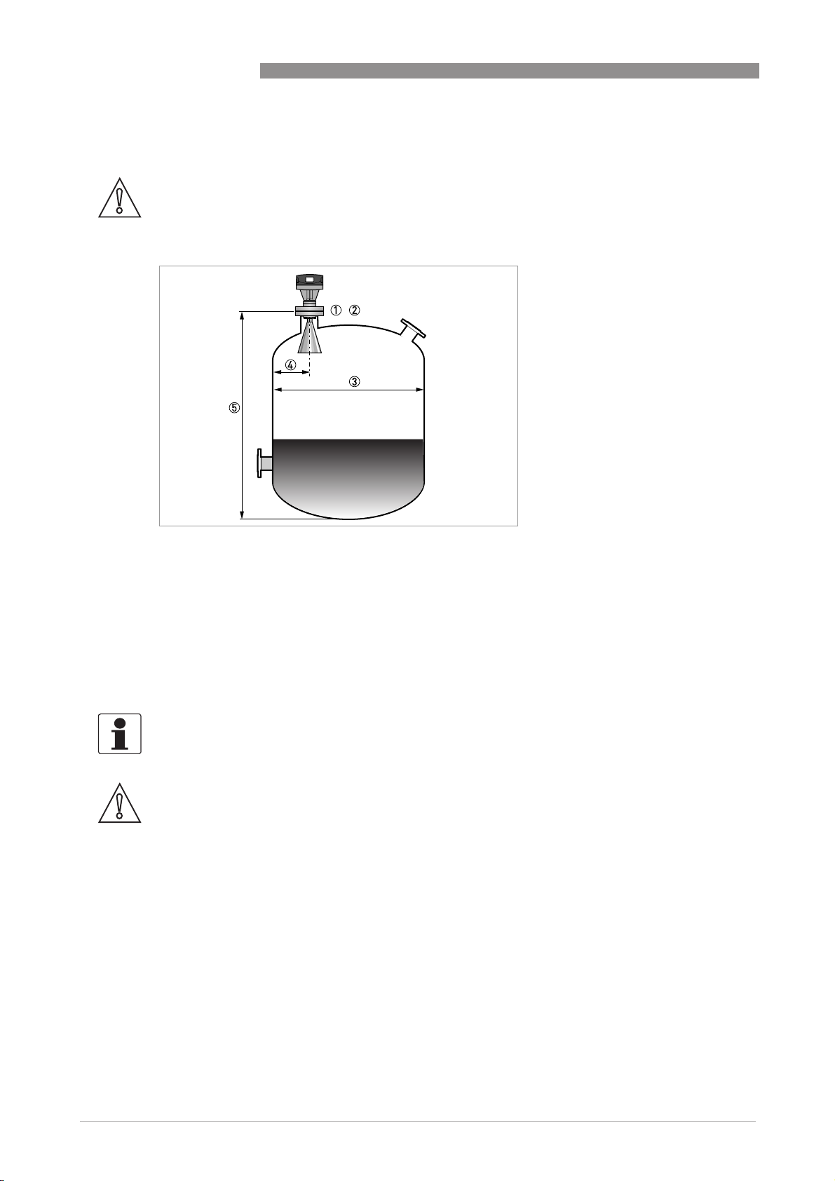
3.5 Theoretical data for nozzle position
CAUTION!
Follow these recommendations to make sure that the device measures correctly.
BM 702 A
Figure 3-2: Recommended nozzle position for liquids, pastes and slurries
1 Nozzles for DN150 or Wave-Stick antennas
2 Nozzles for DN200 antennas
3 Tank diameter
4 Minimum distance of nozzle from the tank wall depending on:
1 1/7 x tank height
2 1/10 x tank height
Maximum distance of nozzle from the tank wall depending on:
1 1/3 x tank diameter
2 1/3 x tank diameter
5 Tank height
INFORMATION!
If possible, do not put a nozzle on the tank centerline.
CAUTION!
Do not put the device near to the product inlet. If the product that enters the tank touches the
antenna, the device will measure incorrectly. If the product fills the tank directly below the
antenna, the device will also measure incorrectly.
16
www.krohne.com 09/2009 - 4000643301 - MA BM 702 A R01 en
Page 17
BM 702 A
INSTALLATION 3
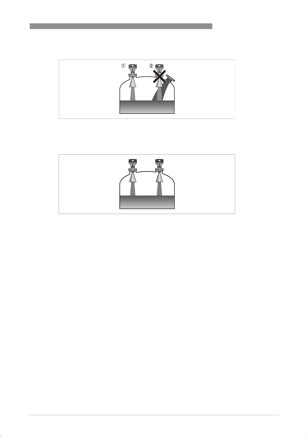
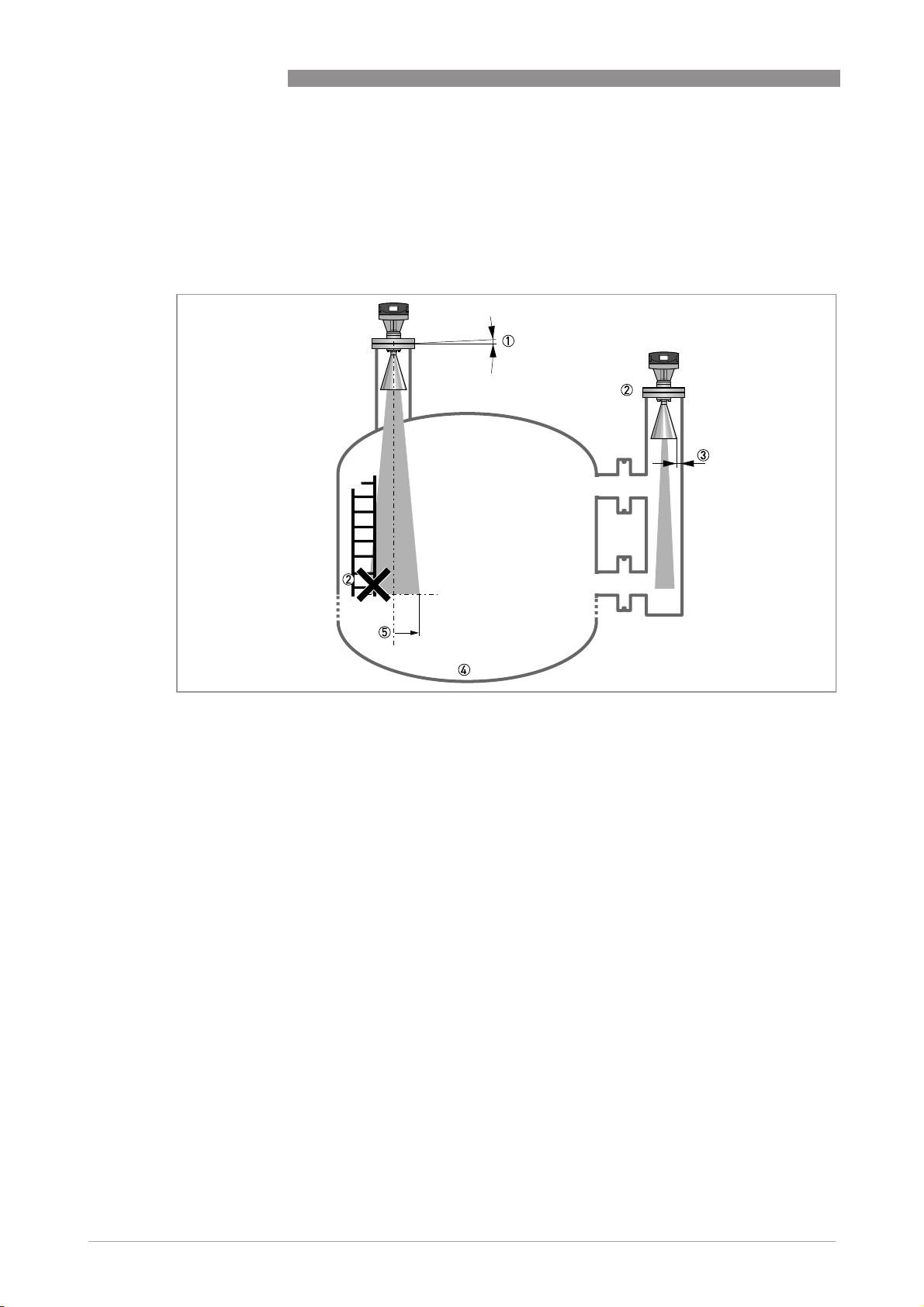
Figure 3-3: Product inlets
1 The device is in the correct position.
2 The device is too near to the product inlet.
Figure 3-4: More than 1 FMCW radar level meter can be operated in a tank
More than 1 FMCW radar level meter can be operated in a tank.
www.krohne.com09/2009 - 4000643301 - MA BM 702 A R01 en
17
Page 18
3 INSTALLATION
3.6 Installation recommendations for liquids
3.6.1 General requirements
We recommend that you prepare the installation when the tank is empty.
BM 702 A
Figure 3-5: General Installation recommendations
1 Do not tilt the device more than 2°.
2 If there are too many obstacles in the radar beam, do an empty spectrum scan (refer to Operation
chamber or stilling well.
3 ≤5 mm / 0.2" max. for high-dielectric constant liquids
4 Curved and conical tank bottoms. Refer to Operation
5 Radius of radar footprint (DN80 Horn antenna): increments of 300 mm/m or 12"/ft (16°)
Radius of radar footprint (DN100 Horn antenna): increments of 220 mm/m or 9"/ft (12°)
Radius of radar footprint (DN150 Horn antenna): increments of 140 mm/m or 5.5"/ft (8°)
Radius of radar footprint (DN200 Horn antenna): increments of 100 mm/m or 4"/ft (6°)
Operation for fine adjustment of the device.
OperationOperation
Operation) or install a bypass
OperationOperation
18
www.krohne.com 09/2009 - 4000643301 - MA BM 702 A R01 en
Page 19

BM 702 A
3.6.2 Installation in stilling wells
Use a stilling well if:
• There is highly conductive foam in the tank.
• The liquid is very turbulent or agitated.
• There are too many other obstacles near to the area where you want to install the device.
• There is an applications with a tank with a floating roof.
INSTALLATION 3
Figure 3-6: Installation recommendations for stilling wells
1 Basic requirements for a stilling well
2 Recommendations for tanks that have no foam
3 Air circulation hole (max. Ø10 mm / 0.4")
4 Maximum level of the liquid
5 Liquid circulation holes (max. Ø10 mm / 0.4")
6 Distance between holes ≥ 50 mm / 2"
7 Clearance between the antenna and the wall of the stilling well ≤ 5mm / 0.2"
8 Sudden change in well diameter ≤ 1 mm / 0.04"
CAUTION!
Installation requirements
•
The stilling well must be electrically conductive.
•
The inside diameter of the stilling well must not be more than 10 mm / 0.4" over the diameter
of the antenna.
•
The stilling well must be straight.
•
The stilling well must have a surface roughness of ±≤0.1 mm / 0.004" or better.
•
There must be no sudden changes in internal diameter greater than 1 mm / 0.04".
www.krohne.com09/2009 - 4000643301 - MA BM 702 A R01 en
19
Page 20

3 INSTALLATION
Installation in tanks containing one liquid and foam
• Drill a pressure equalization hole in the stilling well above the maximum level.
• Deburr the hole.
Installation in tanks containing one liquid or more without foam
• Drill a pressure equalization hole in the stilling well above the maximum level of the top liquid.
i These holes help the liquid to move freely between the stilling well and the tank.
• Deburr the holes.
Floating roofs
If the device must be installed on a tank with a floating roof, install it in a stilling well.
BM 702 A
20
Figure 3-7: Floating roofs
1 Sediment
2 Support fixtures
3 Stilling well
4 Floating roof
5 Product
6 Tank
www.krohne.com 09/2009 - 4000643301 - MA BM 702 A R01 en
Page 21

BM 702 A
INSTALLATION 3
Horizontal cylindrical tanks
If the device:
• is for a horizontal cylindrical tank,
• is in a metallic tank,
• measures a product with a high dielectric constant and
• is on the centerline of the tank,
we recommend that you install it in a stilling well.
Figure 3-8: Horizontal cylindrical tanks
1 The device is installed without a stilling well. There are multiple reflections. Refer to the CAUTION! that follows.
2 The device is installed in a stilling well and measures correctly.
CAUTION!
If the device is installed in horizontal cylindrical tank that contains a high dielectric constant
liquid without a stilling well, do not put it on the tank centerline. This will cause multiple
reflections and the device will not measure accurately. Use the multiple reflections
menu 3.0 Installation > 3.5 Application > 3.5.5 Multip.Refl.
menu 3.0 Installation > 3.5 Application > 3.5.5 Multip.Refl. to keep the effect of multiple
menu 3.0 Installation > 3.5 Application > 3.5.5 Multip.Refl.menu 3.0 Installation > 3.5 Application > 3.5.5 Multip.Refl.
multiple reflections function in
multiple reflectionsmultiple reflections
reflections to a minimum. For more data, refer to "Function description" in the handbook.
www.krohne.com09/2009 - 4000643301 - MA BM 702 A R01 en
21
Page 22

3 INSTALLATION
3.6.3 Bypass chambers
Install a bypass chamber next to the tank if:
• There is highly conductive foam in the tank.
• The liquid is very turbulent or agitated.
• There are too many obstacles in the tank.
BM 702 A
Figure 3-9: Installation recommendations for bypass chambers
1 Bypass chamber
2 Clearance between the antenna and the wall of the stilling well ≤ 5mm / 0.2"
3 Sudden change in well diameter ≤ 1 mm / 0.04"
CAUTION!
Installation requirements
•
The bypass chamber must be electrically conductive.
•
The inside diameter of the bypass chamber must not be more than 10 mm / 0.4" over the
diameter of the antenna.
•
The bypass chamber must be straight.
•
The bypass chamber must have a surface roughness of ±≤0.1 mm / 0.004".
•
There must be no sudden changes in internal diameter greater than 1 mm / 0.04".
22
www.krohne.com 09/2009 - 4000643301 - MA BM 702 A R01 en
Page 23

BM 702 A
INSTALLATION 3
Installation next to tanks containing one liquid and foam
• The top process connection of the bypass chamber must be above the maximum level of
liquid.
• The bottom process connection of the bypass chamber must be below the lowest measured
level of liquid.
Installation next to tanks containing more than one liquid
• The top process connection of the bypass chamber must be above the maximum level of
liquid.
• The bottom process connection of the bypass chamber must be below the lowest measured
level of liquid.
• Additional process connections are necessary for the liquids to circulate freely along the
length of the bypass chamber. These additional process connections must be separated by a
distance equal to or less than the minimum level of the bottom liquid.
Figure 3-10: Installation recommendations for bypass chambers that contain more than one liquid
1 Bypass chamber
2 Distance between connections ≤ the minimum level of the bottom liquid.
3 Additional process connection
www.krohne.com09/2009 - 4000643301 - MA BM 702 A R01 en
23
Page 24

3 INSTALLATION
3.7 How to keep false reflections to a minimum
CAUTION!
If there are false reflections, the device will not measure correctly.
False reflections are caused by:
• Objects in the tank.
• Sharp corners that are perpendicular to the path of the beam.
• Sudden changes in tank diameter in the path of the beam.
If there are too many obstacles in the path of the radar beam, do an empty spectrum scan.
Alternatively, install the device on a bypass chamber or stilling well.
False reflections
BM 702 A
24
Figure 3-11: False reflections and deflector plates
1 Sharp corners and sudden changes in tank diameter can cause the device to measure incorrectly
2 Install a deflector plate to prevent false reflections
3 Deflector plate
www.krohne.com 09/2009 - 4000643301 - MA BM 702 A R01 en
Page 25

BM 702 A
3.8 How to install the device on the tank
3.8.1 How to install a device with a flange connection
Equipment needed:
• Device
• Gasket (not supplied)
Requirements for flange connections
INSTALLATION 3
Figure 3-12: Flange connection
• Make sure the flange on the nozzle is level.
• Make sure that you use the applicable gasket for the flange dimensions and the process.
• Align the gasket correctly on the flange facing of the nozzle.
• Lower the antenna carefully into the tank.
• Tighten the flange bolts.
i Refer to local rules and regulations for the correct torque to apply to the bolts.
www.krohne.com09/2009 - 4000643301 - MA BM 702 A R01 en
25
Page 26

3 INSTALLATION
3.8.2 How to install a device with a threaded connection
Equipment needed:
• Device
• Gasket for G1½ or 1½NPT connection (not supplied)
Requirements for threaded connections
BM 702 A
Figure 3-13: Threaded connection
• Make sure the tank connection is level.
• Make sure that you use the applicable gasket for the connection dimensions and the process.
• Make sure the tank connection is larger than the antenna.
• If the tank connection is smaller than the antenna, remove the antenna from the housing.
i Either provide the means to adapt the device to a larger process connection on the tank (for
example, a plate with a slot), or use the same process connection, but remove the antenna
from the device before installation and attach it from inside the tank.
• Align the gasket correctly.
• Lower the antenna carefully into the tank.
• Turn the threaded connection on the housing to attach the device to the process connection.
• Tighten the connection.
i Refer to local rules and regulations for the correct torque to apply to the connection.
• If the tank connection is smaller than the antenna, attach the antenna from inside the tank.
26
www.krohne.com 09/2009 - 4000643301 - MA BM 702 A R01 en
Page 27

BM 702 A
3.8.3 Field assembly
In general all device versions are delivered in fully assembled condition. However ia a device
should be delivered in parts, or parts are subsequently replaced, the following provedure should
be noted.
INFORMATION!
For any necessary field assembly all parts are included with the delivery (stud bolts, washers,
etc.).
INSTALLATION 3
Figure 3-14: Field assembly of device
1 Signal converter
2 O-ring
3 Distance piece for high-temperature version (option)
4 Upper Teflon
5 Lower Teflon
6 Antenna
7 Antenna extension (option)
8 Connecting flange of device
®
plug
®
plug
• Bolt the Wave-Guide window (flange mount) or distance piece 3, if supplied loose, to the
device.
• Torque for the sets of 4 Allen screws MMMM (key size 5 mm) is max. 8 Nm / 5.8 ft lbf.
®
Caution: Ensure the upper Teflon
plug 4 is kept absolutely dry and clean! Moisture and dirt
will impair the functionality of the device!
• Bolt antenna extension 7 to the antenna 8.
• Torque for the 3 stud bolts AAAA is max. 8Nm / 5.8ftlbf.
Caution: Do not detach bolts HHHH!
www.krohne.com09/2009 - 4000643301 - MA BM 702 A R01 en
27
Page 28

3 INSTALLATION
3.8.4 Antenna purging system (option for horn antenna)
Figure 3-15: Installation of purging system
1 Screw plug
• Remove screw plug ¼" R 1 and screw in screwed tube joint, e.g. Ermeto ¼" R.
BM 702 A
DANGER!
Consult Ex specifications relating to the purging circuit (provided by customer)!
28
www.krohne.com 09/2009 - 4000643301 - MA BM 702 A R01 en
Page 29

BM 702 A
4.1 Safety instructions
DANGER!
All work on the electrical connections may only be carried out with the power disconnected. Take
note of the voltage data on the nameplate!
DANGER!
Observe the national regulations for electrical installations!
DANGER!
For devices used in hazardous areas, additional safety notes apply; please refer to the Ex
documentation.
WARNING!
Observe without fail the local occupational health and safety regulations. Any work done on the
electrical components of the measuring device may only be carried out by properly trained
specialists.
ELECTRICAL CONNECTIONS 4
INFORMATION!
Look at the device nameplate to ensure that the device is delivered according to your order.
Check for the correct supply voltage printed on the nameplate.
4.2 Electrical installation of output
4.2.1 Electrical connection
To open the signal converter, use a screwdriver and release the four visible srews on top of the
housing.
INFORMATION!
The polarity of the 4...20 mA connection is arbitrary.
Figure 4-1: Terminal assignment
1 Terminal current output (polarity independent)
2 Grounding terminal in the housing
www.krohne.com09/2009 - 4000643301 - MA BM 702 A R01 en
29
Page 30

4 ELECTRICAL CONNECTIONS
4.2.2 Non-Ex
Figure 4-2: Electrical connections for non-Ex devices
1 Power supply
2 Resistor for HART
3 14.5...30 VDC for an output of 22 mA at the terminal
4.2.3 Ex i
®
communication
BM 702 A
Figure 4-3: HART® connection to the Ex i circuit with a resistor
1 Intrinsically-safe power supply
2 Zone non-Ex
3 Zone Ex
4 Resistor for HART
5 14.5...30 VDC for an output of 22 mA at the terminal
®
communication
INFORMATION!
®
If the barrier has a HART
terminal, you can connect HART® devices directly to the barrier
without a resistor.
Figure 4-4: HART® connection to the Ex i barrier without a resistor
1 Intrinsically-safe power supply
2 Zone non-Ex
3 Zone Ex
4 14.5...30 VDC for an output of 22 mA at the terminal
30
www.krohne.com 09/2009 - 4000643301 - MA BM 702 A R01 en
Page 31

BM 702 A
4.3 Protection category
INFORMATION!
The device fulfills all requirements per protection class IP66/67 (equivalent to NEMA6-6X).
DANGER!
Make sure the cable gland is watertight.
ELECTRICAL CONNECTIONS 4
Figure 4-5: How to make the installation agree with protection category IP67
• Make sure that the gaskets are not damaged.
• Make sure that the electrical cables are not damaged.
• Make sure that the electrical cables agree with the national electrical code.
• The cables are in a loop in front of the device 1 so water does not go into the housing.
• Tighten the cable feedthroughs 2.
www.krohne.com09/2009 - 4000643301 - MA BM 702 A R01 en
31
Page 32

4 ELECTRICAL CONNECTIONS
4.4 Networks
4.4.1 General information
The device uses the HART® communication protocol. This protocol agrees with the HART®
Communication Foundation standard. The device can be connected either via point-to-point or
operate in a multi-drop network of up to 15 devices.
The output is factory-set to communicate point-to-point.
4.4.2 Point-to-point connection
BM 702 A
Figure 4-6: Point-to-point connection (non-Ex)
1 Address of the device (0 for point-to-point connection)
2 4...20 mA + HART
3 Resistor for HART® communication
4 Power supply
5 HART
6 HART
®
converter
®
communication software
®
32
www.krohne.com 09/2009 - 4000643301 - MA BM 702 A R01 en
Page 33

BM 702 A
4.4.3 Multi-drop networks
ELECTRICAL CONNECTIONS 4
Figure 4-7: Multi-drop network (non-Ex)
1 Address of the device (n+1 for multidrop networks)
2 Address of the device (1 for multidrop networks)
3 4mA + HART
4 Resistor for HART® communication
5 Power supply
6 HART
7 HART
®
®
converter
®
communication software
www.krohne.com09/2009 - 4000643301 - MA BM 702 A R01 en
33
Page 34

5 START-UP
5.1 Start-up checklist
Check these points before you energize the device:
• Are all the wetted components (antenna, flange and gaskets) resistant to the product in the
tank?
• Does the information on the signal converter nameplate agree with the operating data?
• Did you correctly install the device on the tank?
• Do the electrical connections agree with the national electrical codes?
DANGER!
Before you energize the device, make sure that the supply voltage and polarity are correct.
DANGER!
Make sure that the device and the installation agrees with the requirements of the Ex certificate
of compliance.
BM 702 A
34
www.krohne.com 09/2009 - 4000643301 - MA BM 702 A R01 en
Page 35

BM 702 A
OPERATION 6
6.1 Setting parameters via program PC-CAT 2 for Windows 5.0.0
1 PC
2 RS232 / USB
3 HART
4 Load: ≥250 Ω
5 Isolation amplifier
With the program PC-CAT 2 for Windows, version 5.0.0.116 or higher, you can configurate the
devices in a very comfortable way from a PC. Connect the non-intrinsically safe side of the
isolation amplifier over a load between 250 Ω and 350 Ω to the HART
with a serial port of the PC or a USB port.
®
-Adapter
®
adapter and connect it
The used isolation amplifier must be HART
®
compatible.
www.krohne.com09/2009 - 4000643301 - MA BM 702 A R01 en
35
Page 36

6 OPERATION
6.2 Display and operating elements (optional)
Figure 6-1: Display and operating elements (optional)
1 Numeric display, measured values
2 Alphanumeric display, function/unit
3 Bargraph indication
4 6 Markers to display measurement status
5 4 keys for configuration and error interrogation
Key Description Functionality
→ Cursor key • Selects the configuration menu.
• Branches the menu to the next lower level.
• Shifts the cursor* to the next column on the right.
↓ or ↑ Select key • Branches the menu to the next digit on the same level.
• Changes the content (digit, text character) at the cursor*
position.
^ Enter key • Branches the menu to the next higher level.
• Stores newly entered parameters.
• Executes displayed functions.
• Selects special functions (e.g. error memory).
* The cursor position is signalled by inverted representation of the character at the appropriate place.
Table 6-1: Description of key functionality
BM 702 A
36
www.krohne.com 09/2009 - 4000643301 - MA BM 702 A R01 en
Page 37

BM 702 A
6.3 Description of status markers
INFORMATION!
This function is only available for version with local display.
The markers below the local display only show information about the status of
measurement and are no error displays!
1 No current measured value:
No current measured value:
No current measured value:No current measured value:
The device is searching for a new value. If the search for a plausible level fails for a certain time,
"No Measurand" appears as error display.
2 Signal too weak:
Signal too weak:
Signal too weak:Signal too weak:
Mean of reflected microwaves is very low. Gain is automatically stepped up, if possible.
3 Poor spectrum:
Poor spectrum:
Poor spectrum:Poor spectrum:
Brief showing of this marker has no significance. If permanently on, this may result in uncertain
(incorrect) measured values or the error message "No Measurand".
4 No measured value as yet:
No measured value as yet:
No measured value as yet:No measured value as yet:
Evaluable measured values not available after the device has been started up. Measured value
automatically set to the level of the tank bottom. This marker disappears when the first valid
measured value is obtained.
5 Tank bottom:
Tank bottom:
Tank bottom:Tank bottom:
In tanks with dished bottom, for example, the measuring signal can "disappear" if measurements
are carried out near the bottom. The measured value is then automatically set to the level of the
tank bottom.
6 Measurement frozen:
Measurement frozen:
Measurement frozen:Measurement frozen:
Device is in the block distance detection
OPERATION 6
www.krohne.com09/2009 - 4000643301 - MA BM 702 A R01 en
37
Page 38

6 OPERATION
BM 702 A
6.4 Configuration menu (version 7.44)
INFORMATION!
The default settings are marked in bold
No. Function (Fct.) Settings Description
1.0
1.0 Operation
1.01.0
1.1
1.1 Display
1.11.1
1.1.1 Fct. Display Identical with Fct. 3.2.1
1.1.2 Unit Length Identical with Fct. 3.2.2
1.1.3 Unit Convers Identical with Fct. 3.2.3
2.0
2.0 Test
2.02.0
2.1
2.1 Hardware
2.12.1
2.1.1 Master Master hardware test.
2.1.2 Display Display hardware test.
2.1.3 Status Status information for service.
2.2
2.2 Cur.Output I
2.22.2
2.2.1 Value I Value display Display of actual value of the current
2.2.2 Test I Select:
2.4
2.4 Firmware
2.42.4
2.4.1 Master Display Display of master firmware version.
3.0
3.0 Installation
3.03.0
3.1
3.1 Basis Param.
3.13.1
3.1.1 Tank Height Select unit:
3.1.2 Block Dist. Enter:
3.1.3 Antenna Select:
3.1.4 Ant. Extens. Enter:
3.1.5 Dist. Piece Enter:
3.1.6 Stillwell Select:
3.1.7 Ref. Offset Enter:
3.1.8 Tkb. Offset Enter:
Operation
OperationOperation
Display
DisplayDisplay
Test
TestTest
Hardware
HardwareHardware
Cur.Output I
Cur.Output ICur.Output I
Firmware
FirmwareFirmware
Installation
InstallationInstallation
Basis Param.
Basis Param.Basis Param.
3.6 mA / 4 mA / 6 mA / ... / 20 mA / 22 mA
mmmm / cm / mm / inch / ft
Enter:
0.50...30.00 [m]
0.10 [m]...tank height
Standard / Wave stick
0.00 [m]...tank height
0...2000 [mm]
No
No / Yes
NoNo
If "Yes": enter 25...200 [mm]
-10.00...0000...+10.00 [m]
-100.00...0000...+100.00 [m]
bold in the table.
boldbold
output.
Output of selected value to the current
output. With safety query.
Enter tank height. For detailed
information refer to
on page 40. The unit entered here is also
used for all other length entries.
Enter block distance = nonmeasurable
range below bottom edge of flange. For
detailed information refer to
description
Select antenna type. "Wave stick" for all
Wave-Stick versions, except type "SW" for
stillwells. All other = "Standard".
Enter length of antenna extension (not for
Wave-Stick: set to 0)
Enter length of distance piece above
flange (high temp. version = 120 mm).
Selection: without or with still well. With
still well: enter inside diameter in [mm]
(compensates different wave speeds in
still wells)
Reference offset is added to measured
distance values.
Tank bottom offset is added to measured
level values.
on page 40.
Function description
Function
38
www.krohne.com 09/2009 - 4000643301 - MA BM 702 A R01 en
Page 39

BM 702 A
3.2
3.2 Display
3.23.2
3.2.1 Fct. Display Select:
3.2.2 Unit Length Select:
3.2.3 Unit Convers Select:
3.2.4 User Unit Text entry:
3.2.5 Error Msg. Select:
3.3
3.3 Signal Outp.
3.33.3
3.3.1 Function I Select:
3.3.2 Range I Select:
3.3.3 Scale 4 mA Enter:
3.3.4 Scale 20 mA Enter:
3.3.5 Baudrate Select:
3.3.6 Address 0000...15
3.4
3.4 User Data
3.43.4
3.4.1 Language Select:
3.4.2 Entry Code 1 Select:
3.4.3 Code 1 Code entry:
3.4.4 Location Text entry:
3.5
3.5 Application
3.53.5
3.5.1 Auto Tankh. Special function Automatic determination of tank height.
Display
DisplayDisplay
Signal Outp.
Signal Outp.Signal Outp.
User Data
User DataUser Data
Application
ApplicationApplication
Level
Level / Distance / Conversion
LevelLevel
mmmm / cm / mm/ inch / ft
m3
m3 / l (Liter) / US Gal / GB Gal / ft3 / bbl /
m3m3
Free Unit
10 characters
No / Yes
Yes
YesYes
Off / Level
Level / Distance / Conversion
LevelLevel
3.8-20.5E3.6 / 3.8-20.5E22 / 4-20mA / 420mA E=3.6 / 4-20mA E=22
-200.00 [m]...Scale 20 mA /
0.00 [m3]...Scale 20 mA
Scale 4 mA...+200.00 [m] /
Scale 4 mA...99999.99 [m3] /
1200 / 2400 / 4800 / 8600 / 19200 / 38400
Baud
Baud
BaudBaud
GB-USA / D / F / I / E / P / S
No
No / Yes
NoNo
RRREEEUUU
8 characters
4-20mA E=22
4-20mA E=224-20mA E=22
38400
38400 38400
Select function of display (value to be
displayed). For detailed information refer
to
Function description
Select unit for length value to be displayed
(only for level and distance).
Select unit for conversion value to be
displayed ("volume table"). For detailed
information refer to
on page 40.
Enter user-defined unit for the conversion
table.
Select whether error messages to be
shown in display.
Select function of the current output.
Select range/error status for the current
output (hold last value or 3.6 mA/22 mA in
error status).
Enter lower measuring range value for the
current output (4 mA). For detailed
information refer to
on page 40.
Enter full-scale range value for the
current output (20 mA). See also
explanatory notes.
Baud rate for service interface
communication. Normally set to 38400
Enter device address (for HART®
Multidrop, when > 0).
Select language for the optional display.
Switch the access lockout on/off.
If "Yes", for every access a 9-digit entry
code on the 4 keys is necessary.
Enter the entry code for access lockout.
Enter a device identifier.
For detailed information refer to
description
3.5.2 Empty Spect. Select:
3.5.3 Time Const. Value:
3.5.4 Tracing Vel. Value:
3.5.5 Multip.Refl. Select:
Off / On
On / Record
OnOn
1...10
10...100 [s]
1010
0.01...0.50
No
No / Yes
NoNo
0.50...10.00 [m/min]
0.500.50
Recording the profile of the empty tank
(empty-tank spectrum). For detailed
information refer to
on page 40.
Enter time constant for measured-value
filtering.
Enter the maximum rate of change in level
that can occur in operation.
Switch the multi-reflection identifier
on/off.
OPERATION 6
on page 40.
Function description
Function description
Function
on page 40.
Function description
www.krohne.com09/2009 - 4000643301 - MA BM 702 A R01 en
39
Page 40

6 OPERATION
BM 702 A
3.5.6 BD Detection Select:
3.5.7 Function FTB Select:
3.5.8 Epsilon R Enter:
3.5.9 Tanktype Select:
No / Yes
Off
Off / Partial / Total
OffOff
1.1000...8.0000
Storage Tank
Storage Tank / Process Tank
Storage TankStorage Tank
6.5 Function description
6.5.1 Tank height
The tank height (Fct. 3.1.1
connecting flange and the bottom reference point. The bottom reference point is that "point" in
the tank on which the microwaves of the device hit and from which they are reflected. This may
be the tank bottom (symmetrical tank with flat bottom) or the non-horizontal part of the bottom
(e.g. tank with dished bottom) or an additionally fitted plate. The device cannot measure below
this point ("sump"in the tank).
INFORMATION!
When the tank is completely empty and the tank bottom provides good reflections (flat, not
dished bottom!), the tank height can also be automatically determined with the aid of Fct. 3.5.1
"Auto Tankh.". Before confirming, check carefully that the proposed tank height is plausible!
Fct. 3.1.1) is defined as the distance between the top edge of the tank
Fct. 3.1.1Fct. 3.1.1
Yes
YesYes
Switch the block distance (overfill)
identifier on/off. For detailed information
refer to
Select function of tank bottom tracing
system. For detailed information refer to
Function description
Enter relative permittivity of product (only
for Fct. 3.5.7
Select tank type.
"Storage Tank" = smooth product surface
"Process Tank" = slightly disturbed
product surface
Function description
Fct. 3.5.7).
Fct. 3.5.7Fct. 3.5.7
on page 40.
on page 40.
Fct. 3.5.1
Fct. 3.5.1Fct. 3.5.1
6.5.2 Block distance
The "block distance" function (Fct. 3.1.2
measurements are not meant to take place. The value should be at least 10...20 cm / 3.9...7.9"
greater than the length of antenna + antenna extension, or at least 20 cm / 7.9" in the case of the
Wave-Stick.
Signals within the block distance are suppressed; a rise in the tank filling above this limit
(response threshold) will lead to a measuring result corresponding to a distance = block
distance, when Fct. 3.5.6
Fct. 3.5.6 "BD Detection" is switched on.
Fct. 3.5.6Fct. 3.5.6
6.5.3 Scaling of the current output
The scaling of the current output (Fct. 3.3.3
possible lie within the measuring range (between bottom reference point and response
threshold).
By pressing the two upper keys (→ and ↑) or the two lower keys (^ and ↓) at the same time, the
0% setting (= 4 mA) or 100% setting (= 20 mA) can be programmed according to the actual level.
Fct. 3.1.2) defines a zone below the top reference point in which
Fct. 3.1.2Fct. 3.1.2
Fct. 3.3.3: level 1 = 4 mA ; Fct. 3.3.4
Fct. 3.3.3Fct. 3.3.3
Fct. 3.3.4: level 2 = 20 mA) should if
Fct. 3.3.4Fct. 3.3.4
40
www.krohne.com 09/2009 - 4000643301 - MA BM 702 A R01 en
Page 41

BM 702 A
1 Drain the tank completely to the 0% marking (= 4 mA).
This example was written for the case: current output = level (default). For
distance measurement the points 0% (short distance = high level) and
100% (large distance = low level) are exchanged.
2 Press the lower keys (^ und ↓) down, until the asterisks on the display
"Tank Height |********" are replaced by the actual measured distance
value.
If no reliable measurement is possible "No Access" is displayed. Abort by
pressing ^.
3 Then release and press ^. In the lower line: "Sure ? No" is displayed.
4 If this value is not plausible or the tank is not empty, abort by ^. Or
accept the value by pressing ↑ ("Sure ? Yes") and then ^.
OPERATION 6
5 Now the tank height is set.
6 In the next step you can also enter this value as 4 mA scaling (0%). Press
^. In the lower line now: "Sure ? No" is displayed again.
7 If this value shall not be stored, abort by ^. Or accept this 4 mA scaling
by pressing ↑ ("Sure ? Yes") and then ^.
8 Fill the tank to the 100% mark. Use the same procedure for the 100%
point = 20 mA only now by pressing the top keys → and ↑.
This example was written for the case: current output = level (default). For
distance measurement the points 0% (short distance = high level) and
100% (large distance = low level) are exchanged.
If no reliable measurement is possible "No Access" is displayed. Abort by
pressing ^.
9 First the measured distance can be taken as block distance. After this
you can enter or adjust the 20 mA point (100%) according to the actual
level.
100%
www.krohne.com09/2009 - 4000643301 - MA BM 702 A R01 en
41
Page 42

6 OPERATION
6.5.4 Empty-tank spectrum
To enable the device to identify and blank out interference signals, e.g. caused by fixed and
moving tank internals, the tank profile (empty-tank spectrum) needs to be recorded once only
prior to (initial) start-up. For recording, the tank should be completely empty and all moving
parts (e.g. agitators) switched on. If major interference through internals is not expected,
recording of the empty-tank spectrum can also be dispensed with, since the factory has already
carried out and stored a partial empty spectrum of the flange system.
Empty-tank spectrum recording via display
After selecting menu item Fct. 3.5.2
spectrum is currently "On" or "Off". Then press the ^ key if no change is to be made, or use the
↑ key to choose between the following options:
• "On": the empty-tank spectrum is (again) switched on and taken into account for
measurements.
• "Off": the empty-tank spectrum is not taken into account for measurements, but remains
stored and can be switched on again at a later date.
• "Record": the existing empty-tank spectrum is to be deleted and a new one recorded.
BM 702 A
Fct. 3.5.2, press key →. The display then shows whether the empty
Fct. 3.5.2Fct. 3.5.2
After selecting "Record": if other parameters had previously been changed, the query "Store
Yes" is first made as to whether they are to be stored. In this case, confirm by pressing ^. To
record, use the ↑ key to select one of the following options:
• "Max. values": (only maximum values are taken into account when the empty-tank spectrum
is recorded; useful e.g. with "difficult" agitators).
• "Average": (values are averaged; this setting can be used for most applications).
After selecting with the ↑ key, press the ^ key to select "Total" or the ↑ key to select "Partial".
• When "Total" is selected, the empty-tank spectrum is recorded over the entire range (tank
height).
• If the tank has not been fully drained, the empty-tank spectrum can also be recorded up to a
certain distance, in which case the menu item "Partial" should be selected. When this has
been selected, a query takes place by way of the ^ key concerning the distance value up to
which the empty-tank spectrum is to be recorded. The tank area below the current filling
level is then excluded from the empty-tank recording. It is recommended to maintain a safety
distance of 20...30 cm / 7.9...11.8" from the actual product distance.
Subsequently press key ^ to start recording the empty-tank spectrum. The display starts with
"200" and counts down to "0". The sign "Wait ..." is shown in the display. "Ready" appears after
approx. 1...3 minutes. Then press key ^ five times to store the recorded empty-tank spectrum,
which is taken into account for measurements.
42
www.krohne.com 09/2009 - 4000643301 - MA BM 702 A R01 en
Page 43

BM 702 A
6.5.5 Tank bottom tracing mode (FTB)
The device includes an additional function for measuring reliably low levels in tanks with flat
bottom and poorly reflecting products (low dielectric constant). This tank bottom tracing system
(abbreviated FTB) is activated optionally in the vicinity of the tank bottom (max. 20% level) or for
the whole tank area.
If the measurement jumps to the correct level only after filling above a certain level (approx.
0.3…1.0 m / 1…3.3 ft), you can activate the FTB function Fct. 3.5.7
permittivity ε
of 2.0. Since the exact position of the tank bottom must be know for this process, it is advisable
when using the FTB to determine the tank height automatically with an empty tank, using
Fct. 3.5.1
Fct. 3.5.1.
Fct. 3.5.1Fct. 3.5.1
of the tank product must also be set in Fct. 3.5.8
r
OPERATION 6
Fct. 3.5.7 "Partial". The relative
Fct. 3.5.7Fct. 3.5.7
Fct. 3.5.8. If it is not known, enter the figure
Fct. 3.5.8Fct. 3.5.8
Activating FTB function Fct. 3.5.7
measuring range (tank height). This option is intended for tank products with very low
permittivity when also at higher filling level no measurement is possible. With increasing tank
heights, however, measuring accuracy is additionally affected.
Fct. 3.5.7 "Full" expands the tank bottom tracing over the total
Fct. 3.5.7Fct. 3.5.7
6.5.6 Conversion table / volume table
A table consisting of a maximum of 50 points can be stored for non-linear or linear conversion of
the level, e.g. into a volumetric value. This table, however, can only be programmed with the PCCAT 2 program (Fct. 3.7.2
Fct. 3.7.2).
Fct. 3.7.2Fct. 3.7.2
www.krohne.com09/2009 - 4000643301 - MA BM 702 A R01 en
43
Page 44

6 OPERATION
6.6 Sequence for setting parameters (example)
INFORMATION!
Only for version with local display valid.
The following description refers to a storage tank. If the device no longer contains the default
parameters, the keystroke combination for entering the numerical values may differ.
BM 702 A
Activity Keys to be
actuated
Entry into configuration menu → Fct. 1.0
Setting the parameter: tank height ↑↑→→ Fct. 3.1.1
Display of default value → 10.000 m
Input of tank height "5.30 m" →↓→5x↑→3x↑ 05.300 m
Confirm tank height and move to block distance ^↑ Fct. 3.1.2
Display default value → 0.5000 m
Enter block distance "0.60 m" →↑ 0.6000 m
Confirm block distance and move to current
output configuration
Move to lower range value →↑↑ Fct. 3.3.3
Display default value → + 00.000 m
Enter lower range value (0.4 m = 4 mA) 3x→4x↑ + 00.400 m
Confirm lower range value and move to fullscale range value
Display default value → 010.00 m
Enter full-scale value (4.0 m = 20 mA) 2x→↓→4x↑ 004.00 m
Confirm full-scale value and move to empty
tank spectrum
Select: re-record empty spectrum →↑↑ Record
Store changed parameters ^ Store Yes
Confirm and select: averaging ^↑ Average
Confirm and start recording; then wait for
approx. 1...3 minutes!
Confirm and move to tank type ^7x↑ Fct. 3.5.9
Display of default value → Process Tank
Select tank type "storage tank" ↑↑ Storage Tank
Return to measurement function with
confirmation of changed parameters
^^↑↑ Fct. 3.3
^↑ Fct. 3.3.4
^^↑↑→↑ Fct. 3.5.2
^^ Ready
5x^ Starting, then meas.val. display
Content of display after
activity
Operation
Tank Height
Block Dist.
Signal Outp.
Scale 4 mA
Scale 20 mA
Empty Spect.
Tanktype
44
www.krohne.com 09/2009 - 4000643301 - MA BM 702 A R01 en
Page 45

BM 702 A
7.1 Replacement of the signal converter
DANGER!
Before starting, note the parameters of the device and switch off the power supply!
CAUTION!
On pressurized tanks, do not on any account remove the 4 screws HHHH connecting the waveguide
window to the flange!
SERVICE 7
1 Signal converter
2 O-ring
3 Connecting flange
4 Distance piece (for high-temperature version)
1 Disconnect all cables from the terminals in the terminal compartment.
2 Remove the 4 Allen screws MMMM (Allen key size 5 mm) and lift off the signal converter. The flange
unit (incl. waveguide window) will remain tight even with pressurized tanks.
3 Fit the new converter.
4 Reconnect all cables in the terminal compartment. For detailed information refer to
installation of output
5 Check against the enclosed report on settings whether the factory-set parameters are correct
for your application. If not, reset.
6 Record the empty spectrum. For detailed information refer to
42.
on page 29.
Empty-tank spectrum
Electrical
on page
www.krohne.com09/2009 - 4000643301 - MA BM 702 A R01 en
45
Page 46

7 SERVICE
7.2 Spare parts availability
The manufacturer adheres to the basic principle that functionally adequate spare parts for each
device or each important accessory part will be kept available for a period of 3 years after
delivery of the last production run for the device.
This regulation only applies to spare parts which are under normal operating conditions subjects
to wear and tear.
7.3 Availability of services
The manufacturer offers a range of services to support the customer after expiration of the
warranty. These include repair, technical support and training.
INFORMATION!
For more precise information, please contact your local representative.
7.4 Returning the device to the manufacturer
BM 702 A
7.4.1 General information
This device has been carefully manufactured and tested. If installed and operated in accordance
with these operating instructions, it will rarely present any problems.
CAUTION!
Should you nevertheless need to return a device for inspection or repair, please pay strict
attention to the following points:
•
Due to statutory regulations on environmental protection and safeguarding the health and
safety of our personnel, manufacturer may only handle, test and repair returned devices that
have been in contact with products without risk to personnel and environment.
•
This means that the manufacturer can only service this device if it is accompanied by the
following certificate (see next section) confirming that the device is safe to handle.
CAUTION!
If the device has been operated with toxic, caustic, flammable or water-endangering products,
you are kindly requested:
•
to check and ensure, if necessary by rinsing or neutralizing, that all cavities are free from
such dangerous substances,
•
to enclose a certificate with the device confirming that is safe to handle and stating the
product used.
46
www.krohne.com 09/2009 - 4000643301 - MA BM 702 A R01 en
Page 47

BM 702 A
7.4.2 Form (for copying) to accompany a returned device
Company: Address:
Department: Name:
Tel. no.: Fax no.:
Manufacturer's order no. or serial no.:
The device has been operated with the following medium:
SERVICE 7
This medium is: water-hazardous
toxic
caustic
flammable
We checked that all cavities in the device are free from such
substances.
We have flushed out and neutralized all cavities in the
device.
We hereby confirm that there is no risk to persons or the environment through any residual media
contained in the device when it is returned.
Date: Signature:
Stamp:
7.5 Disposal
CAUTION!
Disposal must be carried out in accordance with legislation applicable in your country.
www.krohne.com09/2009 - 4000643301 - MA BM 702 A R01 en
47
Page 48

8 TECHNICAL DATA
8.1 Measuring principle
A radar signal is emitted via an antenna, reflected on the product surface and received after a
time t. The radar principle used is FMCW (Frequency Modulated Continuous Wave).
The FMCW-radar transmits a high frequency signal whose frequency increases linearly during
the measurement phase (called the frequency sweep). The signal is emitted, reflected on the
measuring surface and received with a time delay, t. Delay time, t=2d/c, where d is the distance
to the product surface and c is the speed of light in the gas above the product.
For further signal processing the difference Δf is calculated from the actual transmit frequency
and the receive frequency. The difference is directly proportional to the distance. A large
frequency difference corresponds to a large distance and vice versa. The frequency difference Δf
is transformed via a Fourier transformation (FFT) into a frequency spectrum and then the
distance is calculated from the spectrum. The level results from the difference between tank
height and measuring distance.
BM 702 A
Figure 8-1: Measuring principle of FMCW radar
1 Transmitter
2 Mixer
3 Antenna
4 Distance to product surface, where change in frequency is proportional to distance
5 Differential time delay, Δt
6 Differential frequency, Δf
7 Frequency transmitted
8 Frequency received
9 Frequency
10 Time
48
www.krohne.com 09/2009 - 4000643301 - MA BM 702 A R01 en
Page 49

BM 702 A
TECHNICAL DATA 8
8.2 Technical data
INFORMATION!
•
The following data is provided for general applications. If you require data that is more
relevant to your specific application, please contact us or your local representative.
•
Additional information (certificates, special tools, software,...) and complete product
documentation can be downloaded free of charge from the website (Downloadcenter).
Measuring system
Measuring principle 2-wire loop-powered level transmitter; X-band FMCW radar
Application range Level measurement of liquids, pastes and slurries
Primary measured value Δf (change in frequency) between the emitted and received signal
Secondary measured value Distance, level and volume
Design
Construction The measurement system consists of a measuring sensor (horn or Wave-Stick
Options Integrated graphical display
Accessories Weather protection
Max. measuring range 30 m / 98 ft
Min. tank height 0.5 m / 19.7"
Min. block distance 0.2...0.5 m / 0.7...1.6 ft
Beam angle of antenna Horn DN80 / 3", type 1: 16°
Display and user interface
Display and user interface
Display and user interfaceDisplay and user interface
Display Graphical display (64 x 128 pixels)
Interface languages English, German, French, Italian, Spanish, Portuguese, Swedish
Measurement units Lengths: m, cm, mm, inch, ft
antenna) and a signal converter which is available in a compact version.
High-temperature version (max. +250°C / +480°F, dep. on used gaskets)
Special version (with PFA gaskets) for low temperatures
(min. -60°C / -76°F)
Version for food application with dairy screw or Tri-clamp connection
Antenna purging system for horn antenna (supplied with ¼ NPTF connection)
Wave-Guide antenna
Wave-Stick: PTFE flange plate
Heated or cooled antenna for sticky products or high-temperature applications
Antenna extensions of 100 mm / 3.9" length; 90° bent; S-shaped
Depends on the antenna option, dielectric constant of the product and installation
type. Refer also to "Antenna selection".
Horn DN100 / 4", type 2: 12°
Horn DN150 / 6", type 3: 8°
Horn DN200 / 8", type 4: 6°
Wave-Stick 25 mm / 1": 9°
Wave-Guide / stilling well 25...200 mm / 1...8": Propagation only inside the stilling
well
3
Volume: m
, Liter, US Gal, GB Gal, ft3, bbl, free unit (customer defined)
www.krohne.com09/2009 - 4000643301 - MA BM 702 A R01 en
49
Page 50

8 TECHNICAL DATA
Measuring accuracy
Resolution 1 mm / 0.04"
Repeatability ≤ 0.5 x measuring error
Accuracy Standard: ±10 mm / ±0.4", when distance ≤ 5 m / 16.4 ft or
Reference conditions acc. to EN 60770
Reference conditions acc. to EN 60770
Reference conditions acc. to EN 60770Reference conditions acc. to EN 60770
Temperature +20°C ±5°C / +70°F ±10°F
Pressure 1013 mbar abs. ±20 mbar / 14.69 psig ±0.29 psig
Relative air humidity 60% ±15%
Target Metal plate in an anechoic chamber
Operating conditions
Temperature
Temperature
TemperatureTemperature
Ambient temperature -20…+55°C / -4…+130°F
Storage temperature -40…+85°C / -40…+185°F
Process connection temperature V96 flange system with horn antenna or Wave-Guide:
±0.2% of measured distance, when distance > 5 m / 16.4 ft
Option: ±5 mm / ±0.2", when distance ≤ 5 m / 16.4 ft or
±0.1% of measured distance, when distance > 5 m / 16.4 ft
Functional range: -40...+70°C / -40...+160°F
V96 flange system with horn antenna or Wave-Guide:
V96 flange system with horn antenna or Wave-Guide:V96 flange system with horn antenna or Wave-Guide:
Standard without HT distance piece (K6375 gasket): -20…+130°C / -5…+260°F
(depending on the temperature limits of the gasket material. For other gasket
materials see "Materials" in this table.)
BM 702 A
With HT distance piece (K6375 gasket): -20…+250°C / -5…+260°F
(depending on the temperature limits of the gasket material. For other gasket
materials see "Materials" in this table.)
LP flange system with horn antenna or Wave-Guide:
LP flange system with horn antenna or Wave-Guide:
LP flange system with horn antenna or Wave-Guide:LP flange system with horn antenna or Wave-Guide:
-20…+130°C / -4…+266°F (only available without HT distance piece)
Wave-Stick:
Wave-Stick:
Wave-Stick:Wave-Stick:
PTFE with or without flange plate: -20…+130°C / -5…+260°F
(dep. on flange size and pressure rating. Refer to chapter "Pressure ratings".)
PTFE with or without flange plate and HT distance piece: -20…+150°C / -5…+300°F
(dep. on flange size and pressure rating. Refer to chapter "Pressure ratings".)
PP without flange plate: -20…+100°C / -5…+210°F
(only available without HT distance piece)
Thermal shock resistance <40°C/s / <72°F/s
Pressure
Pressure
PressurePressure
Operating pressure V96 flange system with horn antenna or Wave-Guide:
V96 flange system with horn antenna or Wave-Guide:
V96 flange system with horn antenna or Wave-Guide:V96 flange system with horn antenna or Wave-Guide:
-1…40 bar / -14.5…580 psig
(dep. on flange size and pressure rating. Refer to chapter "Pressure ratings".)
Higher pressures on request.
LP flange system with horn antenna, Wave-Guide or
LP flange system with horn antenna, Wave-Guide or
LP flange system with horn antenna, Wave-Guide orLP flange system with horn antenna, Wave-Guide or
Wave-Stick without flange plate:
Wave-Stick without flange plate:
Wave-Stick without flange plate:Wave-Stick without flange plate:
-1…2 bar / -14.5…29 psig
Wave-Stick with flange plate:
Wave-Stick with flange plate:
Wave-Stick with flange plate:Wave-Stick with flange plate:
-1...16 bar / -14.5...232 psig
(dep. on temperature; Refer to chapter "Pressure ratings".)
50
www.krohne.com 09/2009 - 4000643301 - MA BM 702 A R01 en
Page 51

BM 702 A
Other conditions
Other conditions
Other conditionsOther conditions
Physical properties No effect on measurement results; for reliable measurements the relative
Dielectric constant (εr) εr ≥ 1.5;
Product limitations Liquid ammonia (NH3), liquid hydrogen (H2), liquid helium (He)
Vibration resistance IEC 60068-2-6 and EN 50178 (10...57 Hz: 0.075 mm / 57...150 Hz:1g)
Protection category IP66/67 equivalent to NEMA 6-6X
permittivity should have the following values:
εr < 3: stilling well recommended;
Wave-Stick immersed: εr ≥ 4
TECHNICAL DATA 8
Installation conditions
Installation requirement For detailed information refer to chapter "Installation".
Process connection position Make sure that there are not any obstructions directly below the process
Dimensions and weights For detailed information refer to chapter "Dimensions and weights".
connection for the device.
Materials
Signal converter housing Aluminium with electrostatic powder coating
Sight window: glass
Flange system (V96 and LP),
antenna, antenna extension
Wave-Stick Flanges: Stainless Steel (1.4571 / 316 Ti)
Gaskets K4079 without HT distance piece: -20…+130°C / -5…+260°F
Weather protection (Option) Stainless Steel (1.4301 / 304)
Standard: Stainless Steel (1.4571 / 316 Ti)
Option: Stainless Steel (1.4435 / 316 L), Hastelloy® C4 or B2, Titanium, Tantalum
Information on other materials on request.
Flange plate: PTFE
K4079 with HT distance piece: -20…+250°C / -5…+480°F
K2035 without HT distance piece: -20…+130°C / -5…+260°F
K2035 with HT distance piece: -20…+210°C / -5…+410°F
K6230 without HT distance piece: -20…+130°C / -5…+260°F
K6230 with HT distance piece: -20…+210°C / -5…+410°F
K6375 without HT distance piece: -20…+130°C / -5…+260°F
K6375 with HT distance piece: -20…+250°C / -5…+480°F
FPM without HT distance piece: -20…+130°C / -5…+260°F
FPM with HT distance piece: -20…+200°C / -5…+390°F
FPM/FEP without HT distance piece: -15…+130°C / +5…+260°F
FPM/FEP with HT distance piece: -15…+200°C / +5…+390°F
Silicone/FEP without HT distance piece: -30…+130°C / -20…+260°F
Silicone/FEP with HT distance piece: -30…+200°C / -20…+390°F
PFA without HT distance piece: -30…+130°C / -20…+260°F
PFA with HT distance piece: -30…+200°C / -20…+390°F
Special version: -60…+130°C / -75…+260°F
www.krohne.com09/2009 - 4000643301 - MA BM 702 A R01 en
51
Page 52

8 TECHNICAL DATA
Process connections
Horn antenna or Wave-Guide DN50...200, PN6...64
Wave-Stick DN50...150
Dairy screw connection DIN 11851: DN50, DN65, DN80
Tri-clamp ISO 2852: 2...4"
Electrical connections
Power supply Non-Ex / Ex i: 14.5…30 VDC
Cable entry M20x1.5; ½NPT
Cable gland Standard: M20x1.5
Cable entry capacity (terminal)
U-clamp terminals
(for PA and FE)
ASME B16.5: 2...8", 150/300 lbs/RF
ASME B16.5: 2...6", G1½, 1½NPT
SMS 1145: 51 mm, 63 mm, 76 mm
G½
Options: ½NPT, G½ adapter
0.5…1.5 mm
Max. 4 mm2 / AWG 12
2
/ AWG 20...16
BM 702 A
Output
Description of the used
abbreviations
Current output
Current output
Current outputCurrent output
Output data Distance, level and volume
Measuring range
Load Minimal 0 Ω; max. RL = ((U
Temperature drift ≤ 150 ppm/K
Error signal Acc. to NAMUR NE 43
®
HART
HART
HARTHART
Description
Load
Multidrop operation Yes, current output = 4 mA
U
= external voltage; RL = load + resistance
ext
4…20 mA HART® or 3.8…20.5 mA acc. to NAMUR NE 43 1
High value: 22 mA
Low value: 3.6 mA
HART® protocol via current output
HART® version: V5
≥ 250 Ω at HART® test point;
Note maximum load for current output!
Multidrop address adjustable in operation menu 1…15
- 14.5 VDC) / 22 mA)
ext.
52
www.krohne.com 09/2009 - 4000643301 - MA BM 702 A R01 en
Page 53

BM 702 A
TECHNICAL DATA 8
Approvals and certifications
CE This device fulfils the statutory requirements of the EC directives.
ATEX ATEX II 1/2 G Ex ia IIC T6...T1
Other standards and approvals
Other standards and approvals
Other standards and approvalsOther standards and approvals
EMC EMC Directive 2004/108/EC: EN 61326-2-3:2006
R&TTE R&TTE Directive 1995/5/EC: EN 302 372-2 V1.1.1
1 HART® is a registered trademark of the HART Communication Foundation.
The manufacturer certifies successful testing of the product by applying the CE
marking.
ATEX Directive 94/9/EC: EN 60079-0:2006, EN 60079-11:2007, EN 60079-26:2007
8.3 Pressure ratings
V96 flange system with horn antenna or Wave-Guide:
max. allowable operating pressure
Nominal
Flange rated pressure
diameter
PN16 PN25 PN40 PN64
DN inches bar psig bar psig bar psig bar psig
80 3 16 232 - - 40 580 64 928
100 4 16 232 - - 38 551 55 797
150 6 16 232 - - 34 493 47 681
200 8 16 232 25 362 32 464 45 652
Wave-Stick with flange plate: pressure / temperature rating
1 Pressure in [bar] or [psig]
2 Temperature in [°C] or [°F]
www.krohne.com09/2009 - 4000643301 - MA BM 702 A R01 en
53
Page 54

8 TECHNICAL DATA
8.4 Antenna selection
The graph below shows which antenna to select for the application.
BM 702 A
Graph of tank height / measuring range against dielectric constant ε
r
Figure 8-2: Selection of antenna
a = tank height / measuring range [ft / m]
b = ε
for storage tanks with smooth product surface
r
c = ε
for process tanks or foam
r
d = ε
for agitator tanks with vortex
r
1 Stilling well* (not for agitator tanks)
2 Stilling well* (not for agitator tanks) or antenna type 4
3 Stilling well* (not for agitator tanks); Wave-Stick or antenna type 3 and type 4
4 Stilling well* (not for agitator tanks); antenna type 2, type 3 and type 4 or Wave-Stick
5 Stilling well* (not for agitator tanks) or Wave-Stick
* Stilling well is equal to Wave-Guide antenna and bypass chamber
54
www.krohne.com 09/2009 - 4000643301 - MA BM 702 A R01 en
Page 55

BM 702 A
TECHNICAL DATA 8
8.5 Dimensions
Horn antenna
Horn antenna High-temperature version
Horn antennaHorn antenna
High-temperature version
High-temperature versionHigh-temperature version
b = 215 mm / 8.5" a = 355 mm / 14"
c = 155 mm / 6.1"
e = 198 mm / 7.8"
f = 172 mm / 6.8"
For dimensions of a and Ød, see table below.
Nominal size Antenna Dimensions [mm] Approx.
weight
DN
[mm]
80 3 1 80 110 145 110 9
100 4 2 100 148 177 146 10
150 6 3 140 223 250 220 16
200 8 4 200 335 360 332 21
ASME
[inches]
Type Ød a
(SS 1.4571/
SS 316 Ti)
a
(Hastelloy
®
C4)
a
(Titanium,
Tantalum)
[kg]
Nominal size Antenna Dimensions [inches] Approx.
weight
DN
[mm]
ASME
[inches]
Type Ød a
(SS 1.4571/
SS 316 Ti)
a
(Hastelloy
®
C4)
a
(Titanium,
Tantalum)
[lbs]
80 3 1 3.15 4.33 5.71 4.33 20
100 4 2 3.94 5.83 6.97 5.75 22
150 6 3 5.51 8.78 9.84 8.66 35
200 8 4 7.87 13.19 14.17 13.07 46
www.krohne.com09/2009 - 4000643301 - MA BM 702 A R01 en
55
Page 56

8 TECHNICAL DATA
Wave-Stick
Wave-Stick Wave-Guide
Wave-StickWave-Stick
Wave-Guide Wave-Stick
Wave-GuideWave-Guide
Wave-Stick
Wave-StickWave-Stick
Dairy screw connection
Dairy screw connection
Dairy screw connectionDairy screw connection
BM 702 A
a = Ø25 mm / Ø1.0" a = Ø30 mm / Ø1.2" a = Ø25 mm / Ø1.0"
b = ≥270 mm / 10.6" b = 215 mm / 8.5" b = 205 mm / 8.1"
c = ≥270 mm / 10.6"
Weight: approx. 6 kg / 13.2 lbs (DN50) Weight: approx. 7 kg / 15.4 lbs
(DN50, 1 m / 3.9")
Weight: approx. 4.4 kg / 8.8 lbs
56
www.krohne.com 09/2009 - 4000643301 - MA BM 702 A R01 en
Page 57

BM 702 A
9.1 Parameter check list
BM 702 A Vers.: Device no.:
Menu
Menu modified at
MenuMenu
Fct.
Fct. Configuration parameters (extract)
Fct.Fct.
3.1.1 Tank height:
3.1.2 Block distance:
3.1.3 Antenna:
3.1.4 Antenna extension:
3.1.5 Distance piece:
3.1.6 Stillwell / diameter:
3.1.7 Reference offset:
3.1.8 Tank bottom offset:
3.3.1 Current output function:
3.3.2 Current output range / error:
3.3.3 Min. current scale:
3.3.4 Max. current scale:
3.5.2 Empty spectrum:
3.5.3 Time constant:
3.5.4 Tracing velocity:
3.5.5 Multiple reflections (yes / no):
3.5.6 Block distance ident (yes / no):
3.5.7 Function FTB:
3.5.8 Epsilon R (εr):
3.5.9 Tank type:
modified at
modified atmodified at
Configuration parameters (extract)
Configuration parameters (extract)Configuration parameters (extract)
APPENDIX 9
www.krohne.com09/2009 - 4000643301 - MA BM 702 A R01 en
57
Page 58

10 NOTES
BM 702 A
58
www.krohne.com 09/2009 - 4000643301 - MA BM 702 A R01 en
Page 59

BM 702 A
NOTES 10
www.krohne.com09/2009 - 4000643301 - MA BM 702 A R01 en
59
Page 60

KROHNE product overview
• Electromagnetic flowmeters
• Variable area flowmeters
• Ultrasonic flowmeters
• Mass flowmeters
• Vortex flowmeters
• Flow controllers
• Level meters
• Temperature meters
• Pressure meters
• Analysis products
• Measuring systems for the oil and gas industry
• Measuring systems for sea-going tankers
Head Office KROHNE Messtechnik GmbH & Co. KG
Ludwig-Krohne-Str. 5
D-47058 Duisburg (Germany)
Tel.:+49 (0)203 301 0
Fax:+49 (0)203 301 10389
info@krohne.de
The current list of all KROHNE contacts and addresses can be found at:
© KROHNE 09/2009 - 4000643301 - MA BM 702 A R01 en - Subject to change without notice.
www.krohne.com
 Loading...