

Page 1
©
KROHNE
7.02226.31.00
Status: 06-1999
Installation and operating
instructions
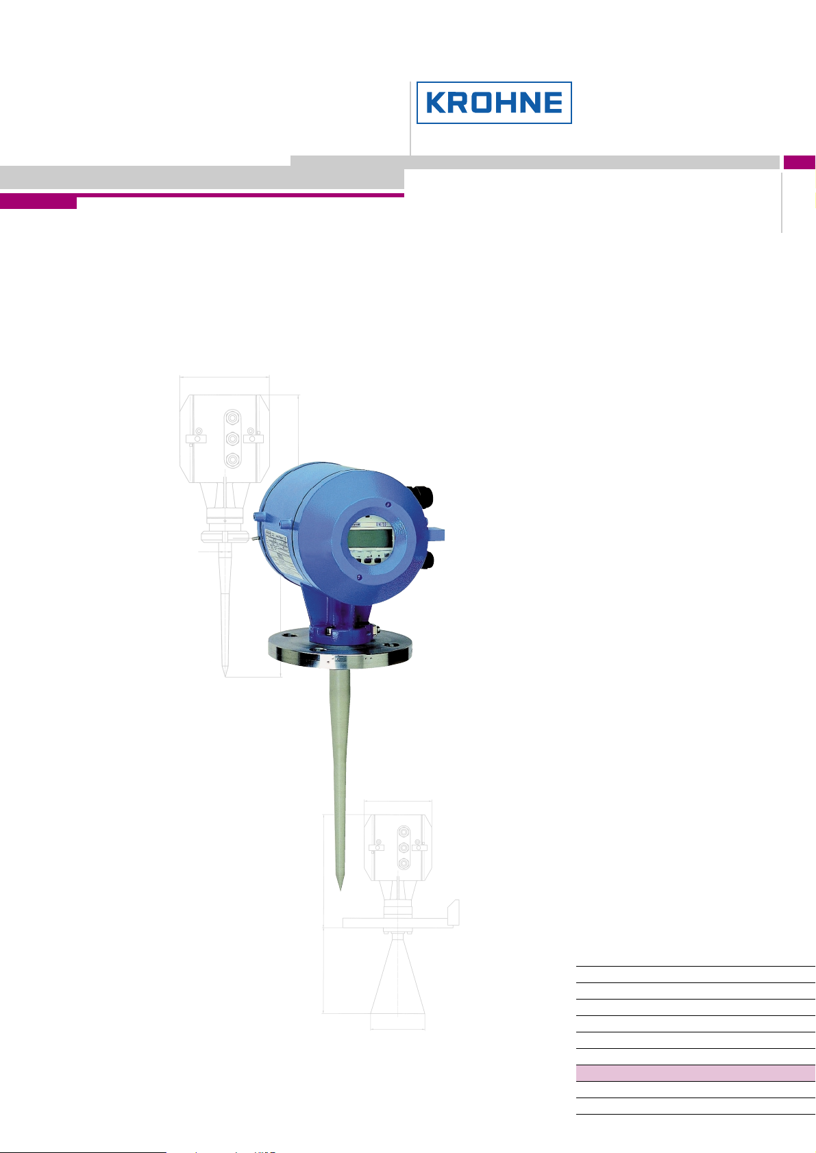
Level-Radar
BM 700
Variable area flowmeters
Vortex flowmeters
Flow controllers
Electromagnetic flowmeters
Ultrasonic flowmeters
Mass flowmeters
Level measuring instruments
Communications technology
Engineering systems & solutions
Page 2

Software History
Intro-
duction
Signal converter User program Instructions
Mth./Yr Hardware Firmware Hardware Operating-
system
04/98 BM 700
Test versions for BM 700.
10/98 BM 700 5.01 PC DOS 5.0
First serial version for BM 700.
5.00PREnn
5.01PRE01
PC DOS 5.0
and higher
and higher
Software Device User
PC-CAT
3.00
PREnn
PC-CAT
3.00
Suppl.
instruction
to BM 70A
10/98 7.02221.11
program
7.02221.11
+ Suppl.
instruction
+ Suppl.
instruction
Items included with supply
The scope of supply includes, in the version as ordered:
• Signal converter bolted to waveguide window and antenna; optionally: antenna
extension, sunshade (with fastening material in each case)
• Shielding material with tightening strap (not for the US market)
• Installation and operating instructions plus instruction card
• Report on factory settings for the signal converter
• Certification and approval documents, unless reproduced in the device
documentation
• Bar magnet for operator control (only for version with local display)
• Wrench for covers
Installation material (stud bolts, flange gasket and cabling) not supplied, to be
provided by customer!
Page 2 BM 700 Installation and Operating Instructions
Page 3

Contents:
page
1 Handling and storage 3
2 Installation 4
2.1 Field assembly 4
2.2 Mechanical installation 5
3 Electrical connection 7
4 Setting the parameters 8
5 Maintenance, error handling 16
6 Safety information 17
7 Technical data (extract) 18
8 BM 700 Level-Radar Type code 19
9 Parameter check list BM 700 21
Appendix 22
Product liability and warranty:
The BM 700 level gauge is designed solely for measuring the level, distance, volume
and reflection of liquids, pastes, slurries, particulate materials and solids.
The BM 700 level gauge does not form part of an overfill protection system as
defined in the WHG (= German water pollution regulation).
Local codes and regulations apply to its use in hazardous areas.
Responsibility as to suitability and intended use of these level gauges rests solely
with the user.
Improper installation and operation of our level gauges may lead to loss of warranty.
In addition, the "General conditions of sale", form the basis of the purchasing
contract.
If you need to return the level gauge to the manufacturer or supplier, please refer to
the information given in Section 5
1 Handling and storage
Safety advice
Depending on the version, the device will weigh between approx. 10 kg and 30 kg.
To carry, use both hands to lift the device carefully by the converter housing. If
necessary, use lifting gear.
When handling the BM 700, avoid hard blows, jolts, impact, etc.
When storing the "Wave-Stick" version, make sure that the device is not placed on its
side on the PTFE antenna, as this may cause the rod to bend.
BM 700 Installation and Operating Instructions Page 3
Page 4

2 Installation
Most of the BM 700 versions are supplied in fully assembled condition. In this case,
you may skip this chapter. However, if a device should be delivered in parts, or parts
are subsequently replaced, the following should be noted.
2.1 Field assembly
• For any necessary field assembly of the
BM 700, all parts are included with the
supply (stud bolts, washers, etc.).
• Bolt the waveguide window (flange mount)
or distance piece, if supplied loose, to the
BM 700. Torque for the sets of 4 Allen
screws M (key size 5 mm): max. 8 Nm ∼
0.8 kpm (5.8 ft lbf).
• Note: Ensure the upper Teflon plug is kept
absolutely dry and clean! Moisture and dirt
will impair functionability of the BM 700!
signal converter
distance piece (for
high-temperature version
up to 250°C (482 °F)
H
BM70 A
connecting flange
antenna extension
O-ring
upper Teflon plug
O-ring
lower Teflon plug
M
M
• Bolt antenna extension to the antenna;
torque for the 3 stud bolts A: max. 8 Nm ∼
0.8 kpm (5.8 ft lbf).
Do not detach bolts H !
Versions:
BM 700
converter
blind
Stick
Flange
plate
Gasket
Stick
BM 700
converter
with Display
High temperature
distance piece
(optional)
Horn
antenna
Gasket
antenna
Horn
antenna
A
Separation
(Metaglass)
Flange
plating
(for Hastelloy,
Ti, Ta)
Wave-Stick
PTFE
Page 4 BM 700 Installation and Operating Instructions
Wave-Stick
w/o plate
(PP or PTFE)
max. 2 bar
max. 2 bar (29 psig)
LP flange system
max. 2 bar (29 psig)
max. 2 bar
with horn antenna
Flange system 96
with horn antenna
Page 5
2.2 Mechanical installation
Hazardous-duty systems:
• The BM 700 Ex is certified in conformity with European Standard for use in Zone
0, 1 and 2 hazardous locations (dependent on version).
• Attention is drawn to the data and information given on the nameplate of the
converter, the nameplate of the flange and the specifications in the approval
certificates.
Safety:
• Surface temperature: The housing of the signal converter can, in extreme
ambient conditions, have a temperature of more than 70°C (158°F)!
• Check material compatibility of antenna, extension, flange, gaskets, and PP or
PTFE (used in all versions) with the product! See also section 8 "Type code"!
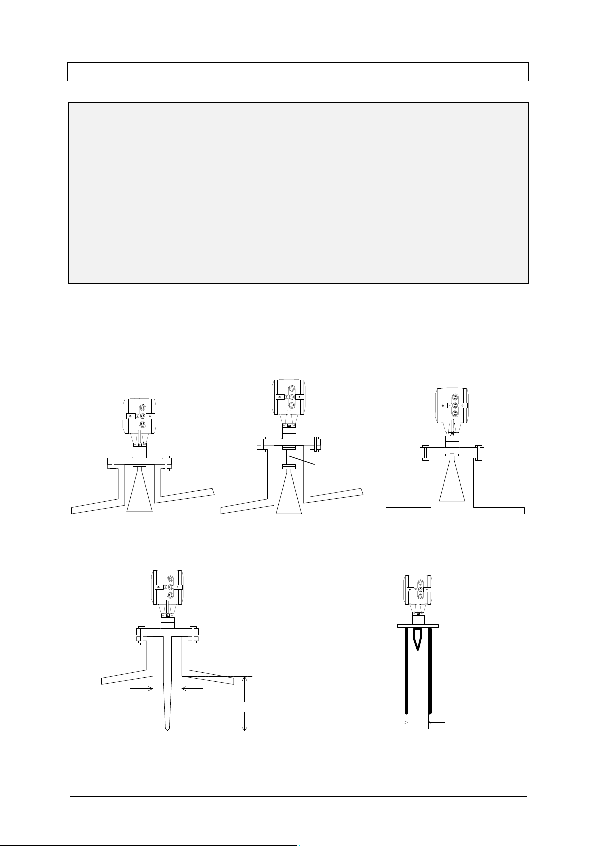
Mounting on the tank nozzle
a) Devices with horn antenna:
The antenna should project out of the nozzle. If necessary, use an antenna extension. Exception: in case of a symmetrical tank fitting.
Antenna
Tank nozzle
Tank nozzle
extension
Tank nozzle
b) Wave-Stick
Note the requirements imposed on nozzle diameter and nozzle length:
Version for
still wells
dia. 40...55 mm
(1.57" to 2.17")
e.g. DN50 (2")
tank nozzle
min. 50 mm
min. 235 mm
BM 700 Installation and Operating Instructions Page 5
Page 6
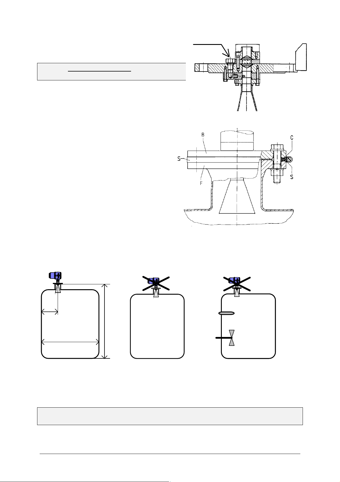
c) Purging device
Do not forget the gasket when
positioning the BM 700 on the tank
nozzle flange. Align BM 700 and gasket,
slightly tighten nuts on stud bolts (by
in the gap
700 flanges and
(both
must fit closely and
Tighten down stud bolt nuts firmly. The
dependent upon the
strength properties of the stud bolts and
Remove screw plug ¼" R and screw in
screwed tube joint, e.g. Ermeto ¼" R.
Consult “Ex“ specifications relating to the
purging circuit (provided by customer)!
Installation on the tank
•
hand).
• Press shielding strip C*
between tank and BM
secure with strap retainer S*
items included with supply).
• Strap retainer S*
overlap both flanges.
* only required for European radio approvals
•
tightening torque is
the pressure rating of the tank.
Positioning on the tank
C* = shielding strip B = BM 700 flange
S* = strap retainer F = tank flange
>1/7×H, but max. 1/3×D
D
H
Recommended distance Do not position in Do not position
from the tank wall tank centreline! above internals!
(multiple reflections!) (interference reflections!)
A Stilling well or Wave-Guide may be mounted in any position on the tank!
When using the PTFE Wave-Stick in hazardous areas of Zone 0, any electrostatic
charging of the stick, e.g. by flow of product, must be avoided!
Page 6 BM 700 Installation and Operating Instructions
Page 7
3 Electrical connection
BM 700 (max. 5 instruments)
BM 700 (max. 5 instruments)
To open the terminal compartment of the signal converter, first open the safety lock
with an Allen key (size: 4 mm) and then use the enclosed special wrench to turn the
cover anticlockwise.
Supply power
Variant Voltage range Recommended fuse protection
24 V DCAC
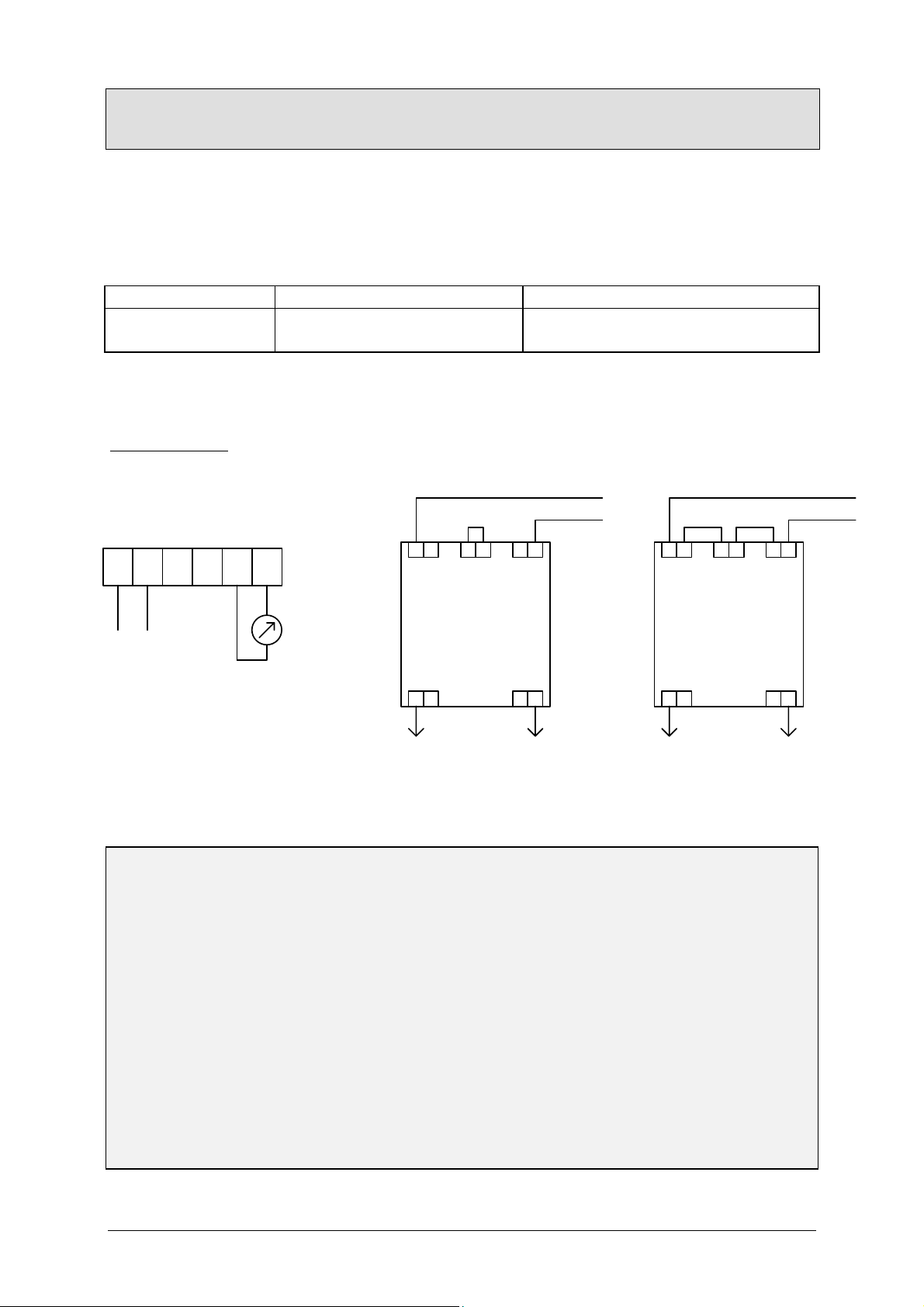
Terminal assignment
Supply power:
Terminal compartment BM 700: External power supply "FEAS, type PSLC242":
19.2 - 28.8 V DC or
20.4 - 26.4 V AC
min. T 0.5 A
230 V AC
L1L1 N N3 4
1 2
Current
output
32 31
-
+
L1L1 N N3 4
+
Power supply
24 V DC (+/-20%)
or
24 V AC (+10/-15%)
< 300 mA
max.350 Ω
Class of protection
The BM 700 level gauge is designed for safety class 1 in conformity with VDE 0106
Part 1.
24 V DCAC supply
When connected to a “functional extra-low voltage with safety separation“ power
source (SELV or PELV) in accordance with VDE 0100, Part 410 or equivalent
(inter)national regulations, connection of a safety conductor (PE) is not required.
Equipotential bonding
When used in hazardous areas, the BM 700 Ex must be incorporated in the PA
equipotential bonding system , irrespective of the type of power supply! If the PA is
connected via a separate conductor, this must be connected to the separate U-clamp
terminal at the “neck“ of the BM 700 Ex. Cancellation of equipotential bonding is only
permitted when the BM 700 is disconnected from supply.
Rated temperature of connecting cables: see Section 6.
4-20mA
-
+ +
Power supply galvanically insulated according to VDE 0551
Dimensions (W×H×D): 55×75×110 mm, usable for rail
mounting
- -
+ +
115 V AC
- -
BM 700 Installation and Operating Instructions Page 7
Page 8

4 Setting the parameters
Setting parameters via program PC-CAT
RS232
Adapter
≥ 120 Ω
With the program PC-CAT, version 3.00 or higher, you can configurate BM 700
instruments in a very comfortable way form a PC. Connect the current output of
BM 700 over a load between 120 Ω and 350 Ω to the Smart adapter (delivered
together with PC-CAT) and connect it with a serial port of the PC.
Local display (optional)
• Numeric display, measured values
‚ Alphanumeric display, function/unit
ƒ Max. 6 markers to display measurement
status
„ 3 keys for configuration and error
interrogation
… Magnetic sensors for operator control
through the closed housing (function
same as the 3 keys)
† Compass field, indicates actuation of a
key
Page 8 BM 700 Installation and Operating Instructions
Page 9

Function of keys (only for version with local display)
Operator control via the keys: For reasons of electrical safety, the keys (below the
display, when housing is open) may only be actuated for servicing and repair work by
specialist personnel, on no account, however, when there is risk of explosion!
Operator control can be carried out with the aid of the supplied bar magnet without
opening the housing. However, a particularly convenient form of parameter setting is
offered by the PC program PC-CAT (special accessories, see above).
→ (cursor key): - selects the configuration menu,
- branches the menu to the next lower level,
- shifts the cursor* to the next column on the right.
↑ (select key): - branches the menu to the next digit on the same level,
- changes the content (digit, text character) at the cursor*
position.
↵ (ENTER key): - branches the menu to the next higher level,
- stores newly entered parameters,
- executes displayed functions,
- selects special functions (e.g. error memory, see Sect. 5).
* The cursor position is signalled by flashing of the character or the option at the appropriate place.
Meaning of status markers (only for version with local display)
The 6 markers below the local display only show information about the status of
measurement and are no error displays!
1: No current measured value: The device is searching for a new value. If the
search for a plausible level fails for a certain time, "SIGNAL DOWN" appears as
error display.
2: Signal too strong: Mean of reflected microwaves is very high. Gain is automa-
tically stepped down.
3: Poor spectrum: Brief showing of this marker has no significance. If permanent-
ly on, this may result in uncertain (incorrect) measured values or the error
message "NO M.VALUE".
4: No measured value as yet: Evaluable measured values not available after the
device has been started up. Measured value automatically set to the level of the
tank bottom. This marker disappears when the first valid measured value is
obtained.
5: Tank bottom: In tanks with dished bottom, for example, the measuring signal
can "disappear" if measurements are carried out near the bottom. The measured value is then automatically set to the level of the tank bottom.
6: Measurement frozen: Device is in the block distance detection (see below).
Description of functions
The table on the following 2 pages provides an overview of all parameters that can
be set in the configuration menu.
This is followed by more precise explanations of some functions and a typical
configuration.
BM 700 Installation and Operating Instructions Page 9
Page 10

Configuration menu (version 5.00 / 5.01)
Function (Fct.) Input range Description
1.0 OPERATION
1.1 DISPLAY
1.1.1 FCT.DISP identical with 3.2.1
1.1.2 UNIT.LENGTH identical with 3.2.2
1.1.3 UNIT.CONV. identical with 3.2.3
2.0 TEST
2.1 HARDWARE
2.1.1 MASTER Master hardware test.
2.1.2 DISPLAY Display hardware test.
2.1.3 STATUS Status information for Service
2.2 CUR.OUTP.I
2.2.1 VALUE I Value display Display of actual value of the current
output.
2.2.2 TEST I Select 2 mA/4 mA/6 mA/...
2.4 FIRMWARE
2.4.1 MASTER Display Display of master firmware version.
2.4.2 DISPLAY Display Display of display firmware version.
3.0 INSTALL.
3.1 BASIS.PARAM
3.1.1 TANKHEIGHT
3.1.2 BLOCKDIST Enter
3.1.3 ANTENNA Select STANDARD
3.1.4 ANT.EXTENS. Enter 0.00 [m] ... tank height Enter length of antenna extension.
3.1.5 DIST.PIECE Enter 0 ... 2000 [mm] Enter length of distance piece above
3.1.6 STILLWELL
3.1.7 REF.OFFSET
3.1.8 TB.OFFSET
3.2 DISPLAY
3.2.1 FCT.DISP
3.2.2 UNIT.LENGTH
3.2.3 UNIT.CONV.
3.2.4 USER UNIT Text entry
3.2.5 ERROR MSG.
... 20 mA/22 mA
Select unit m/cm/mm/
inch/Ft
Enter
0.50 ... 20.00 [m]
0.10 [m] ... tank height
WAVE-STICK
Select NO / YES
If “YES“: enter 25 ... 200 [mm]
Enter -10.00...0...+10.00 [m]
Enter -100.00...0...+100.00 [m]
Select LEVEL
DISTANCE
CONVERSION
Select m/cm/mm/
inch/Ft/
PERCENT/BARGRAPH
Select m3/l(Liter)/US Gal/
GB Gal/Ft3/bbl/PERCENT/
BARGRAPH/USER UNIT
10 characters
Select NO/YES
Output of selected value to the current
output. With safety query.
Enter tank height (see explanatory
notes).
The unit entered here is also used for
all other length entries.
Enter block distance = non-measurable
range below bottom edge of flange (see
explanatory notes).
Select antenna type. WAVE-STICK for
all Wave-Stick versions, except type
"SW" for stillwells. All other =
STANDARD.
flange (high temperature version =
120 mm).
Selection: without or with still well.
With still well: enter inside diameter in
[mm] (compensates different wave
speeds in still wells)
Reference offset is added to measured
distance values.
Tank bottom offset is added to
measured level values.
Select function of display
(value to be displayed).
(see also explanatory notes)
Select unit for length value to be
displayed (only for level and distance).
Select unit for conversion value to be
displayed (“volume table“).
(see explanatory notes)
Enter user-defined unit for the
conversion table.
Select whether error messages to be
shown in display.
Page 10 BM 700 Installation and Operating Instructions
Page 11

Function (Fct.) Input range Description
/DISTANCE
3.3 SIGNAL OUT
3.3.1 FUNCTION I
3.3.2 RANGE I Select 4-20mA
3.3.3 SCALE 4mA Enter -200.00 ... +200.00 [m]
3.3.4 SCALE 20mA Enter -200.00 ... +200.00 [m]
3.3.5 BAUDRATE Select 1200 Bd
3.3.6 ADDRESS
3.3.7 PROTOCOL Select
3.4 USER DATA
3.4.1 LANGUAGE Select GB-USA/D/F/I/E/P/S Select language for the optional
3.4.2 ENTRY CODE 1
3.4.3 CODE 1
3.4.4 LOCATION Enter text (8 characters) Enter a device identifier.
3.5 APPLICAT.
3.5.1 AUTO TANKH. Special function Automatic determination of tank height
3.5.2 EMPTY.SPEC.
3.5.3 TIMECONST.
3.5.4 TRACING.VEL. Value
3.5.5 MULT.REFL.
3.5.6 BD-DETECT.
3.5.7 FUNCT. FTB
3.5.8 EPSILON R Enter
3.5.9 TANKTYPE
Select OFF/LEVEL
/CONVERSION//SW.OUTP.
4-20mA/E2
4-20mA/E22
0.00 ... 99999.99 [m3]
0.00 ... 99999.99 [m3]
Enter 0 ... 255
HART/KROHNE-PC
Select NO/YES
Enter code (RRREEEUUU)
Select OFF/ON/
RECORD
Value 1...10...100 [s]
0.01...0.50...10.00 [m/Min]
Select NO/YES
Select NO/YES
Select OFF/
PARTIAL
1.1000 ... 8.0000
Select STORAGE T./
PROC TANK
Select function of the current output.
Select range/error status for the current
output (hold last value or 2mA / 22mA
in error status).
Enter lower measuring range value for
the current output (4 mA).
(see explanatory notes)
Enter full-scale range value for the
current output (20 mA).
(see explanatory notes)
Baud rate for HART communication
(non-changeable).
Enter device address.
(for HART multidrop)
Select communications protocol
display.
Switch the access lockout on/off.
If YES, for every access a 9-digit entry
code on the 3 keys is necessary.
Enter the entry code for access lockout.
(see explanatory notes).
Recording the profile of the empty tank
(empty-tank spectrum) (see explanatory notes).
Enter time constant for measured-value
filtering
Enter the maximum rate of change in
level that can occur in operation.
Switch the multi-reflection identifier
on/off.
Switch the block distance (overfill)
identifier on/off (see explanatory notes).
Select function of tank bottom tracing
system (see explanatory notes).
Enter relative permittivity of product
(only for Fct. 3.5.7)
Select tank type.
STORAGE T. = smooth product surface
PROC TANK = slightly disturbed product surface
Default values are shown in bold type in the table.
BM 700 Installation and Operating Instructions Page 11
Page 12

Explanatory notes
Tank height
The tank height (Fct. 3.1.1) for the BM 700 is defined as the distance between the
top edge of the tank connecting flange and the bottom reference point. The bottom
reference point is that “point“ in the tank on which the microwaves of the BM 700 hit
and from which they are reflected. This may be the tank bottom (symmetrical tank
with flat bottom) or the non-horizontal part of the bottom (e.g. tank with dished
bottom) or an additionally fitted plate. The BM 700 cannot measure below this point
(“sump“ in the tank).
Note: When the tank is completely empty and the tank bottom provides good
reflections (flat, not dished bottom!), the tank height can also be automatically
determined with the aid of Function Fct. 3.5.1 AUTO TANKH. Before confirming,
check carefully that the proposed tank height is plausible!
Block distance
The “block distance“ function (Fct. 3.1.2) defines a zone below the top reference
point in which measurements are not meant to take place. The value should be at
least 10 - 20 cm greater than the length of antenna+antenna extension, or at least 20
cm in the case of the Wave-Stick.
Signals within the block distance are suppressed; a rise in the tank filling above this
limit (response threshold) will lead to a measuring result corresponding to a distance
= block distance, when Fct. 3.5.6 BD-DETECT. is switched on.
Scaling of the current output
The scaling of the current output (Fct. 3.3.3: level 1 = 4 mA ; Fct. 3.3.4: level 2 = 20
mA) should if possible lie within the measuring range (between bottom reference
point and response threshold).
[Bsp: 0]
Fct. 3.1.4
[e.g.: 0]
tank height
(Fct. 3.1.1)
[e.g.: 5.30 m]
non
measurable
zone
Fct. 3.1.5
+
+
+
+
+
+
+
+
+
+
+
+
+
+
+
+
upper reference point
(top edge of tank connecting flange)
block distance (Fct. 3.1.2)
[e.g.: 0.6 m]
response
threshold
+
+
+
+
+
+
+
+
+
+
+
+
+
+
+
+
measuring
range
Sump
Imax
20
(Fct. 3.3.4)
mA
[e.g.: 4.0 m]
current output
Imin
4
(Fct. 3.3.3)
mA
[e.g.: 0.4 m]
lower reference point
(tank bottom / datum point)
Page 12 BM 700 Installation and Operating Instructions
Page 13

Empty-tank spectrum
To enable the BM 700 to identify and blank out interference signals, e.g. caused by
fixed and moving tank internals, the tank profile (empty-tank spectrum) needs to be
recorded once only prior to (initial) start-up. For recording, the tank should be
completely empty and all moving parts (e.g. agitators) switched on. If major interference through internals is not expected, recording of the empty-tank spectrum can
also be dispensed with, since the factory has already carried out and stored a partial
empty spectrum of the flange system.
Empty-tank spectrum recording via display
After selecting menu item Fct. 3.5.2, press key →. The display then shows whether
the empty spectrum is currently ON or OFF. Then press the ↵ key if no change is to
be made, or use the ↑ key to choose between the following options:
• ON: the empty-tank spectrum is (again) switched on and taken into account for
measurements.
• OFF: the empty-tank spectrum is not taken into account for measurements, but
remains stored in the BM 700 and can be switched on again at a later date.
• RECORD: the existing empty-tank spectrum is to be deleted and a new one
recorded.
After selecting "RECORD": if other parameters had previously been changed, the
query "ACCEPT YES" is first made as to whether they are to be stored. In this case,
confirm by pressing ↵. To record, use the ↑ key to select one of the following options:
• MAX. VALUES: (only maximum values are taken into account when the emptytank spectrum is recorded; useful e.g. with “difficult“ agitators).
• AVERAGE: (values are averaged; this setting can be used for most
applications).
After selecting with the ↑ key, press the ↵ key to select TOTAL or the ↑ key to select
PARTIAL.
• When TOTAL is selected, the empty-tank spectrum is recorded over the entire
range (tank height).
• If the tank has not been fully drained, the empty-tank spectrum can also be
recorded up to a certain distance, in which case the menu item PARTIAL should
be selected. When this has been selected, a query takes place by way of the ↵
key concerning the distance value up to which the empty-tank spectrum is to be
recorded. The tank area below the current filling level is then excluded from the
empty-tank recording. It is recommended to maintain a safety distance of 20 to
30 cm from the actual product distance.
Subsequently press key ↵ to start recording the empty-tank spectrum. The display
starts with “1000“ and counts down to “0“. The sign WAIT flashes in the display.
READY appears after approx. 2 minutes. Then press key ↵ five times to store the
recorded empty-tank spectrum, which is taken into account for measurements.??
Empty-tank spectrum recording via PC-CAT
Connect the BM 700 and press in the display mode of PC-CAT the key combination
Ctrl-L. The type of empty-tank spectrum can be selected by one of the following keys:
1: Max.Values 4: Max. Partial A: Break
2: Average 5: Avg. Partial
BM 700 Installation and Operating Instructions Page 13
Page 14

Tank bottom tracing mode (FTB)
The BM 700 includes an additional function for measuring reliably low levels in tanks
with flat bottom and poorly reflecting products (low dielectric constant). This tank
bottom tracing system (abbreviated FTB) is activated in the vicinity of the tank bottom
(max. 20% level). Given higher levels, the normal measuring method is used
(reflection from the product surface).
If the measurement jumps to the correct level only after filling above a certain level
(approx. 0.3-1.0 m), you can activate the FTB function Fct. 3.5.7 „PARTIAL“. The
relative permittivity εr of the tank product must be set in Fct. 3.5.8. If it is not known,
enter the figure of 2.0. Since the exact position of the tank bottom must be known for
this process, it is advisable when using the FTB to determine the tank height
automatically with an empty tank, using Fct. 3.5.1.
Conversion table/Volume table
A table consisting of a maximum of 50 points can be stored in the BM 700 for nonlinear or linear conversion of the level, e.g. into a volumetric value. This table,
however, can only be programmed with the PC-CAT program (Fct. 3.7.2).
Page 14 BM 700 Installation and Operating Instructions
Page 15

Sequence for setting parameters (example)
(for version with local display)
The following description refers to a storage tank with the parameter examples taken
from the illustration in this Section. If the device no longer contains the default
parameters, the keystroke combination for entering the numerical values may differ.
Activity Keys to be
actuated
Entry into configuration menu
Setting the parameter: tank height
Display of default value
Input of tank height "5.30 m"
Confirm tank height and move to block
distance
Display default value
Enter block distance "0.60 m"
Confirm block distance and move to current
output configuration
Move to lower range value
Display default value
Enter lower range value (0.4 m = 4 mA)
→
↑ ↑ → →
→
→ 9x ↑ →
5x ↑ →3x ↑
↵ ↑
→
→ ↑
↵ ↵ ↑ ↑
→ ↑ ↑
→
3x → 4x ↑
Content of BM 700 display
after activity carried out
Fct. 1.0
OPERATION
Fct. 3.1.1
Tankheight
10.000 m
05.300 m
Fct. 3.1.2
Blockdist
0.5000 m
0.6000 m
Fct. 3.3
SIGNAL OUT
Fct. 3.3.3
Scale 4 mA
+ 00.000 m
+ 00.400 m
Confirm lower range value and move to fullscale range value
Display of default value
Enter full-scale value (4.0 m = 20 mA)
Confirm full-scale value and move to empty
tank spectrum
Select: re-record empty spectrum
Store changed parameters
Confirm and select: averaging
Confirm and start recording; then wait for
approx. 2 minutes!
Confirm and move to tank type
Display of default value
Select tank type "storage tank"
Return to measurement function with
confirmation of changed parameters
↵ ↑
→
2x→ 9x↑ → 4x↑
↵ ↵ ↑ ↑ → ↑
→ ↑ ↑
↵
↵ ↑
↵ ↵
↵ 7x ↑
→
↑ ↑
5x ↵
Fct. 3.3.4
Scale. 20mA
010.00 m
004.00 m
Fct. 3.5.2
EMPTY.SPEC.
RECORD
Accept. Yes
AveragE
READY
Fct. 3.5.9
Tank type
PROC tank
Storage t.
Param.Check,
then START,
then meas.val. display
BM 700 Installation and Operating Instructions Page 15
Page 16

5 Maintenance, error handling
Hazardous-duty systems
• Within the scope of routine checks required to be carried out on systems operated
in hazardous areas (maintaining the system in good working order), the “flameproof enclosure“ (cover on signal converter) should also be visually inspected
for outward damage and signs of corrosion.
• Before opening the “flameproof enclosure“ (e.g. to inspect the inside or for re-
pair work) or the terminal compartment (e.g. to connect or disconnect cables) or
replacing the signal converter in hazardous locations, make sure:
- that the BM 700 Level-Radar has been disconnected from supply,
- before opening the flameproof enclosure allow the prescribed waiting time of 10
minutes to elapse first,
- or that there is no explosion hazard (gas-free certificate!).
Replacement of the signal converter
Before commencing, note the parameters of the BM 700 and switch off the power
supply!
1. Detach safety lock at terminal compartment using Allen key (size 4 mm) and
unscrew cover from terminal compartment using the special wrench. If a sunshade
(option) is fitted, remove this first.
2. Disconnect all cables from the terminals in the terminal compartment.
3. Remove the 4 Allen screws M (Allen key size 5 mm) and lift off the signal converter. The flange unit (incl. waveguide window) will remain tight even with pressurized tanks.
Caution
On pressurized tanks, do not on any account remove the 4 screws H connecting the
wave guide window to the BM 700 flange! DANGER!
4. Fit the new BM 700 converter.
M
5. Reconnect all cables in the terminal
compartment, as described in Section 3.
signal converter
O-ring
6. Check against the enclosed report on
settings whether the factory-set parameters
are correct for your application. If not, reset.
7. Record the empty spectrum, see Section 4.
Important: Make sure that the screw thread of
distance piece
(for hightemperature
version up to 250°C (482°F)
H
BM70
connecting flange
the covers on the terminal and electronic
compartments is well greased at all times.
Returning a BM 700
The party returning a device is obligated to check and ensure that all cavities in the
device are free from dangerous substances (toxic, caustic, flammable, waterendangering), and that a certificate is enclosed with the device confirming that it is
safe to handle.
Page 16 BM 700 Installation and Operating Instructions
Page 17

Error display during measurement (only for versions with local display)
When function 3.2.5 "ERROR. MSG." is set to YES, any error occurring during
measurement is indicated in the display and alternates with the measured value for
as long as the error is present.
In addition, all errors are stored. Press the keystroke combination ↵ ↑ → → to get
into the error list. You can page through the list with key → , and acknowledge the
errors at the end - if required - by "QUIT YES". Press key ↵ twice to return to the
measuring mode.
Fatal errors (FATAL ERROR), that are detected when the device is started up, render
operation of the BM 700 impossible.
6 Safety information
Insulation rating
The insulation of type BM 700 level gauges is rated in conformity with VDE
0110/01.89, equivalent to IEC 664, and takes into account the following ratings:
• overvoltage category for the power line circuit: III
• overvoltage category for the output circuit: II
• insulation contamination level: 2 (inside the device)
Disconnecting device
The type BM 700 level gauge does not feature any device for switching or disconnection.
Hazardous-duty systems
• Types of protection in the BM 700 terminal compartment:
Increased Safety “e“ for signal output and power supply
• Consult the relevant wiring and installation regulations, e.g. VDE 0165, before
mounting, dismantling or making electrical connections in a hazardous area.
• Before making the electrical connection, make sure all cables leading into the
BM 700 Ex are disconnected from supply!
Temperature rating of connecting cables:
The temperature rating of connecting cables is dependent on the maximum temperature of the flange:
Version Max. flange
temperature
Without high temperature
distance piece > 100°C (212°F) 80°C (176°F)
With high temperature
distance piece > 200°C (392°F) 80°C (176°F)
≤ 100°C (212°F)
≤ 200°C (392°F)
Cable temperature
rating
70°C (158°F)
70°C (158°F)
BM 700 Installation and Operating Instructions Page 17
Page 18

7 Technical data (extract)
Tank height (measuring range) 0.5 m to 20 m (1.64 ft to 65.6 ft)
Measuring accuracy (distance) from 1 m (3.3 ft): + 1 cm (0.4")
from 3.3 m (10.8 ft): + 0.3%
Measured-value resolution 1 mm (0.04")
Rate of change in level max. 10 m/min (33 ft/min) (tracking speed)
Connecting flanges
Horn antenna/Wave-Guide DIN 2501 DN 50 to DN 200 / PN 6 to PN 64 and higher;
Shape C to DIN 2526 or others
ANSI B16.5 2” to 8", Class 150 lbs or 300 lbs, RF
Wave-Stick Only DN 50...150 or ANSI 2”...6”, dairy DIN11851
DN50/65/80, Triclamp 2/3/4”, SMS 51/63/76 mm, G 1½"
Max. allowable operating pressure -1 bar (14.5 psig) (vacuum) to max. 64 bar (928 psig) ,
depending on version and flange pressure rating. (see
name plate)
LP flange system with horn antenna, Wave-Guide or Wave-Stick without flange plate
2 bar
V96 flange system with Hornantenne or Wave-Guide:
Connection: nominal dia. Flange rated pressure
PN 16 PN 25 PN 40 PN 64
DN mm inches bar psig bar psig bar psig bar psig
80 3 16 232 --- --- 40 580 64 928
100 4 16 232 --- --- 38 551 55 797
150 6 16 232 --- --- 34 493 47 681
200 8 16 232 25 bar 362 32 464 45 652
Wave-Stick: max. 16 bar (232 psig), temperature-dependent:
[bar]
[psig]
+16
+232
46 - 0.3·T[°C] bar
Pressure
+14
-14
Operating temperature
+1
-1
-20 +150 °C+100
-4 +212 +302 °F
Temperature T
LP flange system: -20°C (-4°F) to +150°C (302°F)
745 - 2.42·T[°F] psig
at flange V96 flange system:
(see also chapter 8) Basic version: -30°C (-22°F) to +130°C (266°F)
Special version: min. - 60°C (-76°F)
High temp. version, FFKM: max. +250°C (482°F)
Kalrez 2035: max. +210°C (410°F)
FPM (Viton) or FEP-coated: max. +200°C (392°F)
PTFE-Wave-Stick: -20°C (-4°F) to + 150°C (302°F),
pressure depend
PP-Wave-Stick: -20°C (-4°F) to + 100°C (212°F)
Page 18 BM 700 Installation and Operating Instructions
Page 19

Product temperature Unrestricted, provided ambient temperature and flange
Material "Metaglass" ring
(for Hastelloy, Ti, Ta)
temperature are within the specified limits
Ambient temperature Signal converter (T
): - 20°C (-4°F) to + 55°C (131°F)
amb
Power supply
24 V DCAC 19.2 - 28.8 V DC or 20.4 - 26.4 V AC (45 - 66 Hz)
Power consumption (typical) approx. 6 W; AC: approx. 12 VA
Microwaves
Measuring principle FMCW Radar
Frequency range X-Band 8.5 - 9.9 GHz
Antenna radiation angle Type 3: ± 8° Type 4: ± 6° Wave-Stick: ± 9°
Ex-e current output HART® (active)
Current 4 - 20 mA; without or with error message 2 mA or 22 mA
Accuracy and linearity 0.15 %; TC=100 ppm/K
Load impedance < 350 Ohm
Digital communication HART®
Ambient conditions
Environment class Locations exposed direct to open-air climate,
D1 Severity in conformity with EN 60654-1
Protection category
(converter) IP66 / IP67 (equivalent to NEMA 4 and 4X)
Electrical connection
Cable entries: 3 x M25 × 1.5 (US: with adapter ½" NPT) (delivered with
2 cable glands 9-16 mm (0.35"-0.63") and 1 blind cap)
Terminals: Cable cross-section 0.5-2.5 mm² (AWG 20-14)
(solid conductor: max. 4 mm² (AWG 12))
U-clamp terminals (for PA and FE) cable cross-section max. 4 mm² (AWG 12)
8 BM 700 Level-Radar Type code
Series V96 or LP: Series WS:
Terminal cover
Name plate
Flange system
xxx
Converter cover
Name plate
Converter
High temperature distance piece
(optional)
Marking
(not for LP version)
xxx
Marking
Flange material
Flange plating
Terminal cover
Stick
(LPTFE/PTFE/PP)
Converter cover
Name plate
Converter
Name plate
Flange system
xxx
optional: antenna
(LP horn antenna)
Marking
Flange material
optional: flange plate
(Vers. LPTFE/PTFE)
BM 700 Installation and Operating Instructions Page 19
Marking
Flange plating
(for Hastelloy)
Page 20

Marking of the signal converter (see name plate):
BM 700 non-Ex version for non-hazardous areas
BM 700 / E-EEx Ex version for hazardous areas,
terminal compartment in Increased Safety „e“
Marking of the Flange systems (see name plate on flange):
..(1).. ....(2)...... non-Ex version for non-hazardous areas
..(1).. ....(2)...... – E Ex ..(3).. Ex version for hazardous areas
(1) Series
V96 Flange system V96
(with „Metaglass“ as versions with horn antenna or Wave-Guide)
WS Wave-Stick
(plastics rod antenna or short stick for still wells)
LP LP version
(with horn antenna or Wave-Guide)
(2) Materials of the parts in contact with the product
- Series V96:
» Antennas and flanges:
SS Flange and antenna of stainless steel
used material: see marking on flange
HB Flange plating and antenna of Hastelloy B (e.g. B2)
used material: see marking on plating
HC Flange plating and antenna of Hastelloy C (e.g. C4 or C22)
used material: see marking on plating
Ti Flange plating and antenna of Titanium
Ta Flange plating and antenna of Tantalum
Mo Flange plating and antenna of Monel
» gasket material:
FFKM Gaskets of FFKM, e.g. Kalrez™ 4079 or Parofluor™ V3819-75
K2035 Gaskets of Kalrez™ 2035
FPM Gaskets of FPM, e.g. Viton™
FEP Gaskets FEP-coated (FPM core)
- Series WS
LPTFE Stick and flange plate of conductive PTFE
PTFE Stick and flange plate of PTFE
SS PTFE stainless steel PTFE, gasket of FFKM
also for version „LP horn antenna“
SS PP stainless steel PP, gasket of FPM (Viton™)
(3) Application conditions, equipment group II
(explosive atmosphere by gases, vapours, mists)
1G equipment category 1, application in Zone 0
(versions V96, or Wave-Stick LPTFE or PTFE with Metaglass)
2G equipment category 2, application in Zone 1
(Wave-Stick PP or PTFE without Metaglass, or LP flange system)
(free) Without Ex approval (e.g. LP version)
Page 20 BM 700 Installation and Operating Instructions
Page 21

Limits of temperature at flange:
Version Minimum flange temperature Maximum flange temperature
(1)+(2) of the
type code
Standard
version
Special version
with marking
„2.4610“ at the
Without high
temperature
distance piece
With high
temperature
distance piece
Metaglas ring
V96 ... FFKM
V96 ... K2035
V96 ... FPM
V96 ... FEP
WS LPTFE
WS PTFE
WS SS PTFE
WS SS PP
- 30°C (- 22°F) - 60°C (-76°F) +130°C (+266°F) +250°C (+482°F)
- 30°C (- 22°F) - 60°C (-76°F) +130°C (+266°F) +210°C (+410°F)
- 30°C (- 22°F) - 60°C (-76°F) +130°C (+266°F) +200°C (+392°F)
- 30°C (- 22°F) - 60°C (-76°F) +130°C (+266°F) +200°C (+392°F)
- 40°C (- 40°F) ––– +130°C (+266°F) +150°C (+302°F)
- 40°C (- 40°F) ––– +130°C (+266°F) +150°C (+302°F)
- 20°C (- 4°F) ––– +130°C (+266°F) +150°C (+302°F)
- 20°C (- 4°F) ––– +100°C (+212°F) +100°C (+212°F)
9 Parameter check list BM 700
Menu item changed on Version:
Fct. Configuration parameters (extract)
3.1.1 Tank height
3.1.2 Block distance
3.1.3 Antenna
3.1.4 Antenna extension
3.1.5 Distance piece
3.1.6 Stillwell / diameter
3.1.7 Reference offset
3.1.8 Tank bottom
3.3.1 Current output, function offset
3.3.2 Current output range/error
3.3.3 Min. current scale
3.3.4 Max. current scale
3.5.2 Empty spectrum
3.5.3 Time constant
3.5.4 Tracking speed
3.5.5 Multiple reflections (yes/no)
3.5.6 Block distance ident (yes/no)
3.5.7 Function FTB
3.5.8 Epsilon R
3.5.9 Tank type
BM 700 Installation and Operating Instructions Page 21
Page 22

Appendix
(for Germany)
Gazette 129, 20.11.1989
Decree 1117/1989
General licence No. 353 for radio transmitting and receiving installations
The installation and operation of the radio transmitting and receiving system "BM 70 Level
Radar" and "BM 70 Ex Level Radar" manufactured by Firma KROHNE Messtechnik GmbH &
quency in the 8.1 9.4 GHz frequency range, is hereby authorized pursuant to §§ 1 and 2 of
the law concerning telecommunication systems as adopted in the
dated 03.07.1989. The radio systems may only be operated inside totally enclosed metal
tanks.
1.
sector, including radio systems, must not suffer any interference.
2. -mentioned type designations
tent with the models examined and tested by the Central App mu-
-
-
"Postsignum Z G490353X" and the name of KROHNE Messtechnik GmbH & Co. KG,
4100 Duisburg, and the type designation "BM 70 Level Radar" or "BM -Ex Level
3. The identification mark must be embossed or engraved on the housing or on a plate made
of metal or similarly strong material. The plate must be attached to the housing in such a
way that it is impossible to remove or can only be removed by the use of force. The
identification mark must be visible at all times from the outside.
4. The operator of such radio systems has no benefit of protection whatsoever against
interference from other telecommunication systems or telecommunication equipment (e.g.
including radio systems that are duly operated in the same frequency range).
5. The above-mentioned radio systems may not be linked to other telecommunication
systems or telecommunication equipment without special approval from the Deutsche
Bundespost.
6. This "general licence" can at any time be revoked in toto - or in isolated cases can also be
revoked for individual radio systems by the relevant local licensing authority.
Additional notes for manufacturer and users
1. The manufacturer of these generally licensed radio systems has the responsibility towards
the Deutsche Bundespost to ensure that a reprint of this "general licence" accompanies
each and every instrument brought onto the market under the above-mentioned
certification mark.
2. The licence to link these radio systems with other telecommunication systems or
telecommunication equipment is governed by the respective requirements (provisions
concerning private-sector cabled telecommunication equipment, and the
telecommunication regulations). Information in this respect is available from the
appropriate telecommunication offices (acceptance and testing service).
281-3 A 3552-2/A
Page 22 BM 700 Installation and Operating Instructions
Page 23

Bundesministerium für Post und Telekommunikation Gazette 23/95 1421
Decree 241/1995
Extension of the general licence No. 353 for radio transmitting and receiving
installations
To Gazette Decree 1117/1989, page 2066
The above-mentioned general licence for radio installations issued to the company of
KROHNE Messtechnik GmbH & Co. KG, 47058 Duisburg, shall with immediate effect also
include radio installations that operate at a frequency in the frequency range of 8.1 - 9.9
GHz, for the same purpose are placed by the company on the market and which are marked
in accordance with the general licence. At the same time, the purpose is extended to level
measurements in concrete tanks having a minimum wall thickness of 19 cm. The radio
installations may only be operated in fully enclosed tanks.
314-1A 3552-2/A
CE Manufacturer's declaration:
DECLARATION OF CONFORMITY
We, KROHNE Messtechnik GmbH & Co.KG
Ludwig - Krohne - Straße 5
D - 47058 Duisburg
declare on our own responsibility that the products
• BM 700 Level-Radar
to which this declaration refers, are in conformity with the following standards:
• EN 50081 - 1 : 1993 - 3
• EN 50082 - 2 : 1995 - 3
• pr EN 50178 : 1994 - 8
• EN 61010 - 1 : 1993 - 4
in accordance with the provisions of Directives 89 / 336 / EEC and 73 / 23 / EEC.
Duisburg, 01.09.1998
(Place and date of issue) (signed: Company Management)
BM 700 Installation and Operating Instructions Page 23
Page 24

Funktechnische Zulassung
Amtsbl 129, 20.11.1989
Fernmeldewesen
Vfg 1117/1989
Allgemeingenehmigung Nr. 353 für Sende- und Empfangsfunkanlagen
Das Errichten und Betreiben der Sende- und Empfangsfunkanlage "BM 70 Level Radar"
sowie "BM 70-Ex Level Radar" der Firma KROHNE Meßtechnik GmbH & Co. KG, 4100
Duisburg, für Fernwirkzwecke (Füllstandsmessungen in Metalltanks) auf einer Frequenz im
Frequenzbereich 8,1 - 9,4 GHz, wird aufgrund der §§ 1 und 2 des Gesetzes über
Fernmeldeanlagen in der Fassung der Bekanntmachung vom 03.07.1989 hiermit genehmigt.
Die Funkanlagen dürfen nur innerhalb allseits geschlossener Metalltanks betrieben werden.
1. Andere Fernmeldeanlagen und Telekommunikationseinrichtungen, die öffentlichen
Zwecken dienen, sowie Funkanlagen dürfen nicht gestört werden.
2. Funkanlagen, die unter den vorgenannten Typenbezeichnungen in den Verkehr gebracht
werden, bedürfen keiner besonderen Genehmigung im einzelnen, wenn sie mit den beim
Zentralamt für Zulassungen im Fernmeldewesen (ZZF) technisch geprüften Baumustern
elektrisch und mechanisch übereinstimmen und mit dem Zulassungszeichen der
Deutschen Bundespost wie folgt: "Postsignum Z G490353X" sowie mit dem Namen der
Firma KROHNE Meßtechnik GmbH & Co. KG, 4100 Duisburg, und der Typenbezeichnung
"BM 70 Level Radar" bzw. "BM 70-Ex Level Radar" gekennzeichnet sind.
3. Die Kennzeichnung muß in das Gehäuse bzw. auf einem Plättchen aus Metall oder ähnlich
festem Material eingeprägt oder eingraviert sein. Das Plättchen muß so mit dem Gehäuse
verbunden sein, daß es nicht oder nur mit Gewalt von diesem entfernt werden kann. Die
Kennzeichnung muß von außen jederzeit sichtbar sein.
4. Der Betreiber solcher Funkanlagen genießt keinerlei Schutz vor Störungen durch andere
Fernmeldeanlagen und Telekommunikationseinrichtungen (z.B. auch durch Funkanlagen,
die ordnungsgemäß im gleichen Frequenzbereich betrieben werden)
5. Die obengenannten Funkanlagen dürfen ohne eine besondere Genehmigung der
Deutschen Bundespost nicht mit anderen Fernmeldeanlagen oder
Telekommunikationseinrichtungen verbunden werden.
6. Diese "Allgemeingenehmigung“ kann insgesamt - oder im Einzelfall auch für einzelne
Funkanlagen durch die örtlich zuständige Genehmigungsbehörde - jederzeit widerrufen
werden.
Zusatzhinweise für die Herstellerfirma und die Benutzer
1. Die Herstellerfirma dieser allgemein genehmigten Funkanlagen hat sich gegenüber der
Deutschen Bundespost verpflichtet, jedem unter dem o.g. Zulassungszeichen in Verkehr zu
bringenden Gerät einen Nachdruck dieser "Allgemeingenehmigung" beizufügen.
2. Die Genehmigung zum Verbinden dieser Funkanlagen mit anderen Fernmeldeanlagen oder
Telekommunikationseinrichtungen richtet sich nach den jeweiligen Vorschriften (Bestimmungen über private Drahtfernmeldeanlagen bzw. der Telekommunikationsordnung).
Auskünfte hierzu erteilen die zuständigen Fernmeldeämter (Abnahme- und Prüfdienst).
281-3 A 3552-2/A
Page 24 BM 700 Installation and Operating Instructions
Page 25

Bundesministerium für Post und Telekommunikation Amtsblatt 23/95
1421
Vfg 241/1995
Erweiterung der Allgemeingenehmigung Nr. 353 für Sende- und Empfangsfunkanlagen
Zur AmtsblVfg 1117/1989, S.2066
Die obengenannte Allgemeingenehmigung für Funkanlagen der Firma KROHNE Meßtechnik
GmbH & Co. KG, 47058 Duisburg, erstreckt sich ab sofort auch auf die Funkanlagen, die auf
einer Frequenz im Frequenzbereich 8,1 - 9,9 GHz arbeiten, von der Firma für den gleichen
Verwendungszweck in den Verkehr gebracht werden und die entsprechend der
Allgemeingenehmigung gekennzeichnet sind. Gleichzeitig wird der Verwendungszweck auf
Füllstandsmessungen in Betontanks mit einer Mindestwandstärke von 19 cm erweitert.
Die Funkanlagen dürfen nur in allseits geschlossenen Tanks betrieben werden.
314-1A 3552-2/A
CE-Herstellererklärung:
KONFORMITÄTSERKLÄRUNG
Wir, KROHNE Messtechnik GmbH & Co.KG
Ludwig - Krohne - Straße 5
D - 47058 Duisburg
erklären in alleiniger Verantwortung, dass die Produkte
• BM 700 Level-Radar
auf die sich diese Erklärung bezieht, mit den folgenden Normen übereinstimmen:
• EN 50081 - 1 : 1993 - 3
• EN 50082 - 2 : 1995 - 3
• pr EN 50178 : 1994 - 8
• EN 61010 - 1 : 1993 - 4
gemäß den Bestimmungen der Richtlinien 89 / 336 / EWG und 73 / 23 / EWG.
Duisburg, 01.09.1998
(Ort und Datum der Ausstellung) (gez. Geschäftsführung)
BM 700 Installation and Operating Instructions Page 25
 Loading...