

Page 1
Installation and
operating instructions
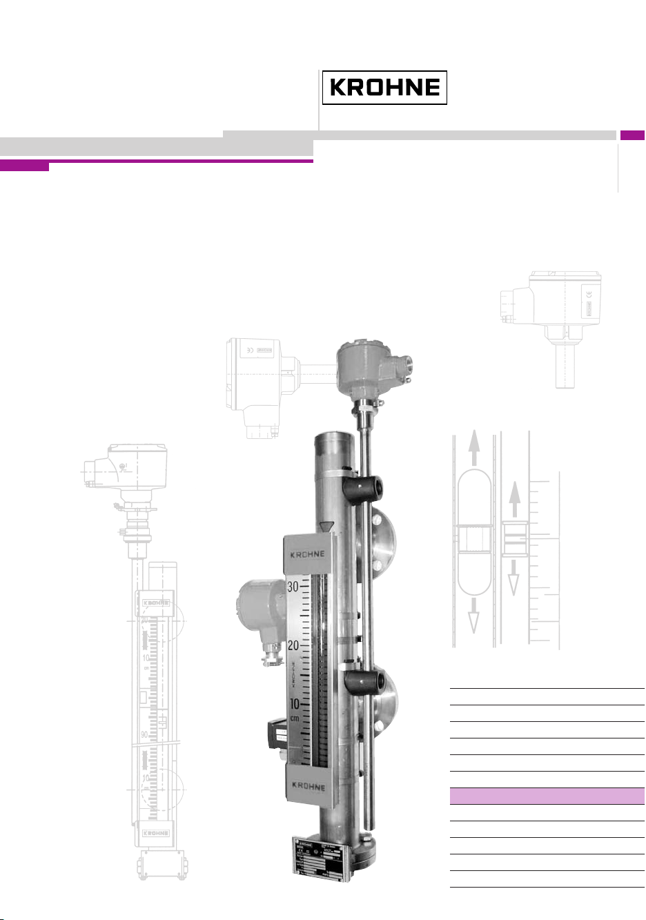
Bypass Level Indicator
BM 26 A
For level or interface
measurement of liquids
©
KROHNE 10/2006 7.02186.26.00
CMD
Variable area flowmeters
Vortex flowmeters
Flow controllers
Electromagnetic flowmeters
Ultrasonic flowmeters
Mass flowmeters
Level measuring instruments
Communications engineering
Engineering systems & solutions
Switches, counters, displays and recorders
Heat metering
Pressure and temperature
Subject to change without notice.
Page 2

Contents
General advice on safety.............................................................................................................4
Description: BM 26 A bypass level indicator with magnetic flaps or bar scale ..................... 4
Documentation symbols ............................................................................................................. 5
Handling .......................................................................................................................................5
Product liability and warranty.....................................................................................................5
Items supplied.............................................................................................................................. 5
Standards / Approvals................................................................................................................. 6
Official approvals and certificates .............................................................................................7
Principal gauge components......................................................................................................7
1
Installation .........................................................................................................................8
1.1 Packing and storage .............................................................................................................8
1.2 BM 26 A construction details............................................................................................... 10
1.3 Mechanical installation requirements ..................................................................................12
1.4 Mounting on the tank........................................................................................................... 13
1.5 Start-up procedure ..............................................................................................................14
1.6 True level indication ............................................................................................................ 15
1.6.1 Level measurement using the local indicator and scale .................................................. 15
1.6.2 Floats ..................................................................................................................... 16
1.6.3 Changing the process conditions .................................................................................... 18
1.6.4 Correcting the scale position to accurately read true liquid level..................................... 20
1.6.5 Functional check of local level display (bar indicator only).............................................. 22
Level transducer .............................................................................................................23
2
2.1 General notes...................................................................................................................... 23
2.2 Transmitters ........................................................................................................................ 24
2.2.1 Transmitter versions for the BM 26 A.............................................................................. 24
2.2.2 Electrical connections .....................................................................................................24
3
Limit switches / contacts................................................................................................ 26
3.1 General notes...................................................................................................................... 26
3.2 Designation code for defining limit switch versions .............................................................26
3.3 Limit switch options for the BM 26 A (non-Ex)..................................................................... 26
3.4 Limit switch options for the BM 26 A (ATEX version) .......................................................... 27
3.5 How to use a limit switch..................................................................................................... 27
3.5.1 Operating principle .......................................................................................................... 27
3.5.2 Installation ..................................................................................................................... 27
3.5.3 Overall dimensions of limit switches mounted on measuring tube ..................................29
3.5.4 Limit switch dimensions (without bracket and clamp)...................................................... 30
3.5.5 Electrical connections .....................................................................................................31
3.6 Fine adjustments to the limit switch trigger point................................................................. 33
3.6.1 General notes.................................................................................................................. 33
3.6.2 Fine adjustments to the limit switch trigger point............................................................. 33
3.6.3 Switching point diagram and offset values for limit switches........................................... 34
2 Installation and Operating Instructions BM 26 A
Page 3

4
Special versions.............................................................................................................. 35
4.1 Low-temperature versions AG-TR-IC/TR............................................................................ 35
4.2 High-temperature versions HR-IC/HR................................................................................. 35
4.3 Heating system for measuring tube BM 26 A/B .................................................................. 36
4.4 Liquid/liquid interface measurement BM 26 A/TS ............................................................... 36
5
Maintenance .................................................................................................................... 37
6
Ordering spare parts ...................................................................................................... 37
7
Technical data................................................................................................................. 38
7.1 Technical data: BM 26 A ..................................................................................................... 38
7.2 Technical data: level transmitter modules ........................................................................... 40
7.3 Technical data: limit switches.............................................................................................. 41
7.4 Guide tube assembly materials........................................................................................... 42
7.4.1 Maximum operating conditions for BM 26 A with 316 Ti steel measuring tube ............... 42
7.4.2 Flange categories for operating conditions in a 316Ti steel measuring tube .................. 42
7.4.3 Maximum operating conditions for BM 26 A with 316 L steel measuring tube ................ 43
7.4.4 Flange categories for operating conditions in a 316L steel measuring tube ................... 43
7.5 BM 26 A weights and dimensions ....................................................................................... 44
7.5.1 Weights ..................................................................................................................... 44
7.5.2 Indicator dimensions ....................................................................................................... 44
7.5.3 Overall dimensions of measuring tube classes (with loose or welding neck flanges) ..... 44
7.5.4 Distance of welding neck flange raised facing from measuring tube axis ....................... 47
8
Measuring principle ........................................................................................................ 48
Appendices ................................................................................................................................ 49
Appendix A: Declaration of conformity: CE............................................................................ 49
Appendix B: Declaration of conformity: Pressure Equipment Directive 97/23/EC .............. 50
Appendix C: EC-Type Examination Certificate INERIS 02ATEX0088X ................................. 51
If you need to return level gauges for testing or repair to KROHNE..................................... 71
Installation and Operating Instructions BM 26 A 3
Page 4
General advice on safety
This manual gives a complete set of instructions for the installation, operation and maintenance of
the ATEX version of the BM 26 A Bypass Level Indicator.
This instrument is designed to function at near constant pressure conditions.
The instrument must be installed and used by suitably qualified personnel.
Our conformity declaration is limited to the parts of the level indicator that are under pressure,
excluding parts that may be dismantled (e.g. valves).
Events that are not taken into account in the calculations include: exceptional risks such as
earthquakes, bad weather, acts of destruction (such as sabotage, terrorism, vandalism, etc.) and
fire.
WARNING
Special regulations are applicable to the use of equipment in hazardous locations,
and these are described in this booklet. Data is supplied on explosion protection.
Description: BM 26 A bypass level indicator with magnetic flaps or bar scale
The BM 26 A bypass level indicator is used for measuring level, interface or volume in open or
pressurized tanks. It is mounted adjacent to the tank and uses the principle of communicating
vessels – the liquid level in the measuring tube corresponds to the liquid level in the tank. Due to its
design, the unit is suitable for use in connection with corrosive, toxic or flammable substances and in
severe service conditions.
The local indicator consists of:-
• A bar indicator (follower magnet) in a Pyrex glass tube as standard
• or a flap indicator (yellow/black magnetic flaps) in a Pyrex glass tube.
No power is required for local liquid-level indication.
Optionally, the unit can be equipped or retrofitted with an electrical analogue level transducer
system and/or limit switches.
Use in hazardous areas
The BM 26 A bypass level indicator is approved for use in explosive atmospheres when equipped
with the appropriate options. It is imperative that the approval certificate details and boundary
conditions are observed.
Special measures must be taken when using titanium floats in order to avoid
friction between the titanium and stainless steel causing sparks in an inflammable
gaseous environment.
The standard design calculation does not take into account the theoretical
coefficient of corrosion. The product circulating in the vessel must not have
properties that give rise to surface erosion.
4 Installation and Operating Instructions BM 26 A
Page 5
Documentation symbols
CAUTION
Information that, if not followed, may lead to actions resulting in incorrect
functioning of the device.
Handling
Product liability and warranty
The BM 26 A bypass level indicator is designed exclusively for liquid-level, liquid/liquid interface or
volume measurement, depending on the scale and float selected by the customer.
Special codes and regulations apply to its use in hazardous areas.
Responsibility as to suitability and intended use of this bypass level indicator rests solely with the
operator.
Improper installation and operation of these bypass level indicators may lead to loss of warranty.
In addition, the “General conditions of sale” forming the basis of the purchase contract are
applicable.
If the bypass level indicator needs to be returned to KROHNE, please read and follow the
instructions given at the end of this manual.
Items supplied
• BM 26 A bypass level indicator option: with or without current output or limit switches
• These installation and operating instructions
• Approval documents / certificates of conformity (for hazardous duty only)
Supplied without mounting accessories (stud bolts, flange gaskets and wiring to be provided by
customer).
WARNING
Information that, if not followed, may lead to actions resulting in measurement
error, personal injury and/or damage to the device.
Information and instructions for Ex applications
Information that must be used to observe the safety requirements for installation,
operation and maintenance in hazardous areas. If instructions are not followed, this
may result in personal injury, damage to the device and/or incorrect functioning of
the device.
WARNING
The device normally weighs from 14.5 kg or 32 lb to 40kg or 88 lb. Carry the device
using at least two people, lifting it by the process connections. Lifting gear may also
be used but no attempt should be made to lift the device by the measuring scale,
level transducer or other attached equipment.
Installation and Operating Instructions BM 26 A 5
Page 6
Special certificates (Optional: supplied on customer demand only)
• Test certificate to EN 10204: pressure test, dye penetration test, radiographic test, leak-tightness
test, ultrasonic test, helium leak test, surface cleanness and material
Standards / Approvals
In compliance with European Directive 94/9/EC (ATEX 100a), the bypass level
indicators described in these instructions conform to European Standards
EN50014, EN 50020, EN50018, EN13463-1 and EN 50284 and are certified for
use in hazardous locations by the INERIS certification agency under INERIS
02ATEX0088X when equipped with the appropriate options.
WARNING
The details given in this approval certificate together with its boundary conditions
must be observed.
This instrument also conforms to the European Union Pressure Equipment Directive 97/23/EC.
Ex Safety Instructions
ATEX-certified BM 26 A level indicators can be used in explosive atmospheres of all flammable
substances in Gas Group IIC (with the exception of cases given in these instructions) and
applications requiring Category 1 / 2 G and 1 G equipment. The instrument must be installed and
used by suitably qualified personnel.
Ex Equipment Category Definitions
Category 1 / 2 G – instruments
(for applications where the Exd-rated explosion-proof box is used)
The signal converter for current output and limit switch options are located in hazardous areas
requiring instruments qualified as being category 2. The process connection and tank wall form an
interface between zones for category 1 and 2 equipment. The indicator measuring elements (float
and measuring tube) are qualified as being category 1. The G rating means that the instrument is
qualified for gas environments.
Category 1 G - instruments
The signal converter for current output, limit switch options and measuring components are located
in hazardous areas requiring instruments qualified as being category 1.
6 Installation and Operating Instructions BM 26 A
Page 7
Official approvals and certificates
Application Approved by Instrument version Certification mark
ATEX certification
*This EC-type Examination Certificate is available on KROHNE’s download centre webpage on
http://www.krohne.com.
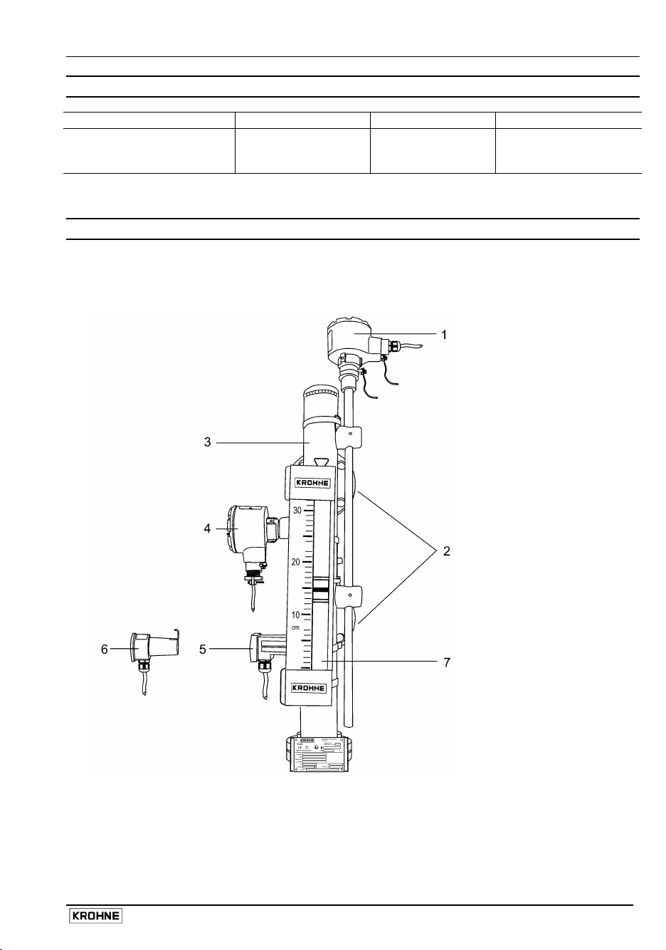
Principal gauge components
Installation and Operating Instructions BM 26 A 7
INERIS BM 26 A Certificate no.
INERIS 02ATEX0088X*
1
Level
transducer
(cable entry
fitting not
supplied)
2 Process
connections
3 Measuring tube
(bypass
chamber)
containing float
loaded with
magnets
4 MS 15 /EXD
limit switch
(cable entry
fitting not
supplied)
5 MS 15 /STD or
/EXI limit switch
6 MS 20 /STD or
/EXI limit switch
(shown
separate from
assembly, may
replace or be
used with items
4 and 5)
7 Scale clamped
adjacent to
measuring tube
integrating a
Pyrex tube with
float-following
indicator bar.
Page 8
1 Installation
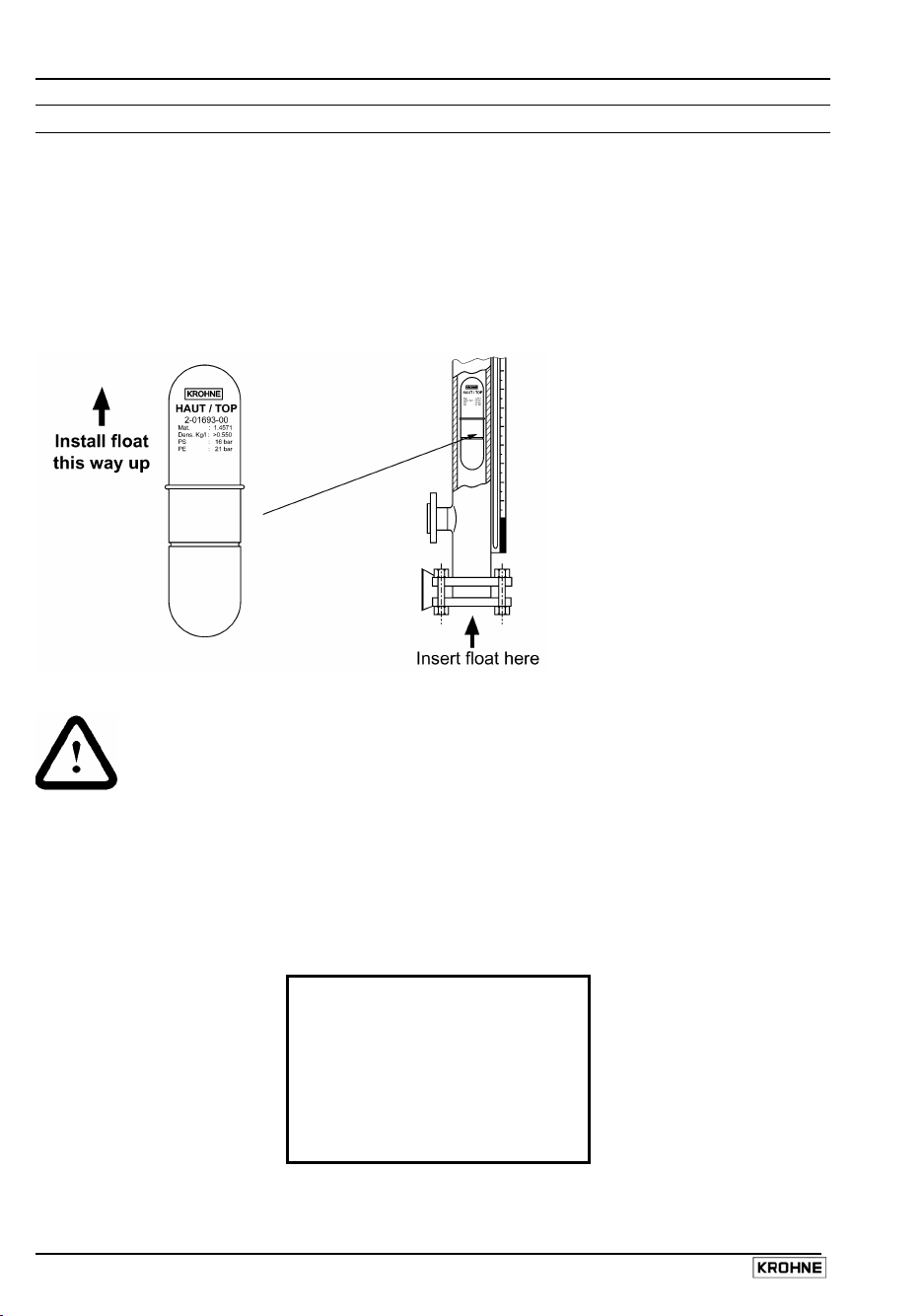
1.1 Packing and storage
Floats packed separately
1
2 Align gaskets.
3 Tighten nuts using the correct torque with regards to the strength of bolts specified for the
To install, remove the bottom flange and insert the float – the right way up – into the guide
chamber.
vessel pressure rating, connecting flange and material.
CAUTION
Make sure that the guide tube is free of foreign bodies
(dirt, loose objects, etc.).
Floats held in position during transit by a plastic locking clip
This should be removed from the guide tube before installation through the bottom connection
flange. Follow the procedure below:
Step 1
Check measuring tube for a red sticker next to the bottom process connection.
ATTENTION!
Retirer la tige de sécurité
maintenant le flotteur
ATTENTION !
Take away transport safety
device for float
ACHTUNG !
Transportsicherung für
Schwimmer entfernen
8 Installation and Operating Instructions BM 26 A
Page 9
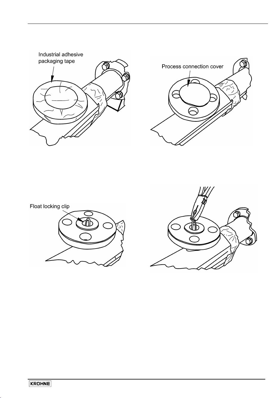
Step 2
Undo adhesive tape around
bottom process connection
Step 3
Remove process connection plastic
protective cover
Step 4
Locate clip
Step 5
Remove clip with a pair of pliers
Installation and Operating Instructions BM 26 A 9
Page 10
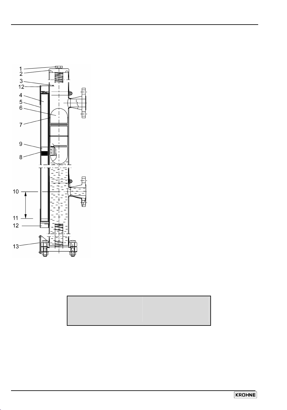
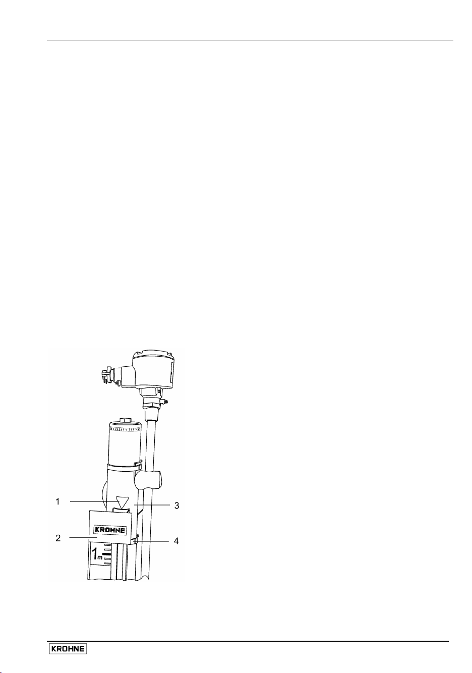
1.2 BM 26 A construction details
The diagram below shows a standard BM 26 A/C/RR without level transducer and switch options
1 Vent plug
2 Measuring tube
3 Red triangle reference mark giving
factory-calculated zero position of
measuring scale
4 Glass tube for indicator
5 Scale
6 Float (magnets mounted in lower half)
7 Liquid level
8 Mid-point of indicator
9 Indicator (standard follower bar)**
10 Zero point of measurement
(centreline of lower connecting flange)
11 Scale zero
12 Stop (red KROHNE plate)
13 Instrument nameplate
* optional flap indicator available (see section 8)
Details:
Item 12 – The red KROHNE plate at the bottom of the scale (item 5) has a label listing the product
and the operating conditions. For example :
Working pressure :
Working temperature :
Density :
Fluid :
6 bar g
25 C
0.778 s g.
cyclohexane
10 Installation and Operating Instructions BM 26 A
Page 11
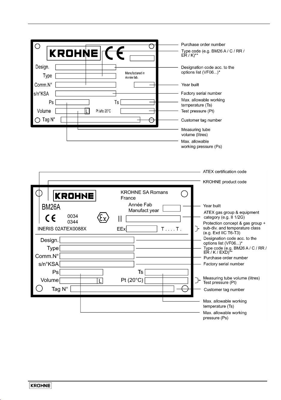
Item 13A – BM 26 A Standard nameplate
Item 13B – BM 26 A ATEX nameplate
* See BM 26 A Data Sheet for a list of standard options and designation codes
** Type code is defined as:
Product code/Process connections/Material code/Design/Level transducer/Contact/Approval
Installation and Operating Instructions BM 26 A 11
Page 12
Type code
Type code element Code Code definition
Product code BM 26 A Bypass Level Indicator (A model)
Process connections C
D
E
F
Construction material code RR Stainless steel
Design No info
B
AG
IC/TR
IC/HR
Level transducer No info
ER
Contact No info
K
Approval No info
EXI
EXD
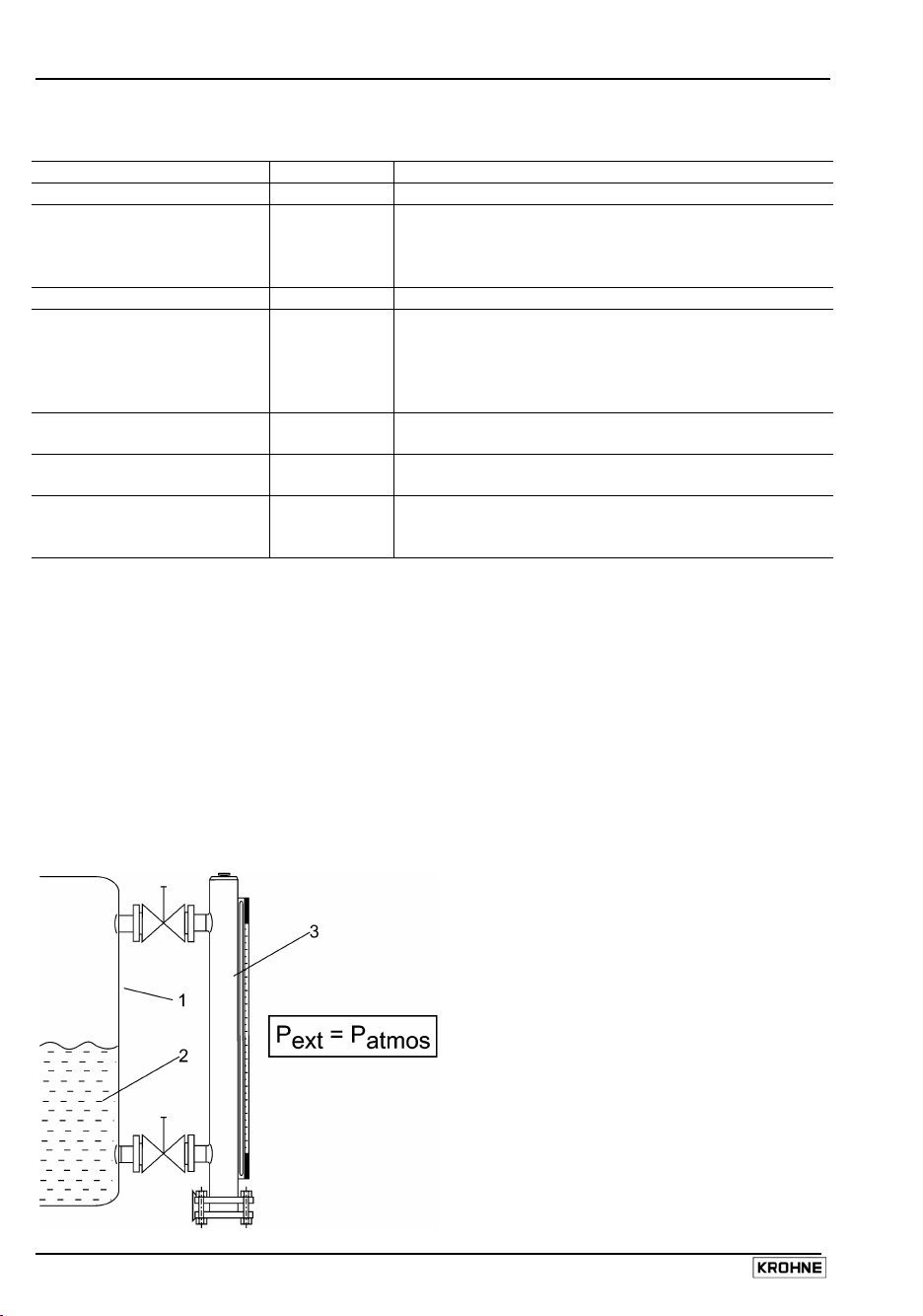
1.3 Mechanical installation requirements
Ensure that the requirements given below have been followed:
• The effective pressure of the installation (the maximum permitted by the pressure limiting valve)
must never be greater than the maximum permitted pressure, P
nameplate. The test pressure, P
• The user must be sure that materials in contact (guide tube, float, gaskets, etc) with the fluid
used are compatible with the fluid and conform to ageing characteristics of the fluid used and the
measurement environment. These have either been recommended in the instructions or form the
subject of a particular specification in the contract.
• The external pressure (P
ext
, is given on the order documents and BM 26 A nameplate.
t
) must be equal to atmospheric pressure(P
Two lateral connections
Two axial connections
One top lateral entry and one bottom axial exit
One bottom lateral entry and one top axial exit
Standard design
Heater
Anti-freeze version -40°C / -40°F
With low temperature insulation
With high temperature insulation
Without level transducer
With level transducer
Without limit switches
With limit switches
Standard, no approval
For EEx – intrinsically safe applications
For EEx – flameproof applications
, marked on the instrument
s
).
atmos
1 Tank
2 Liquid product
3 BM 26A level-liquid indicator
(measuring tube):
Vertical installation only!
12 Installation and Operating Instructions BM 26 A
Page 13
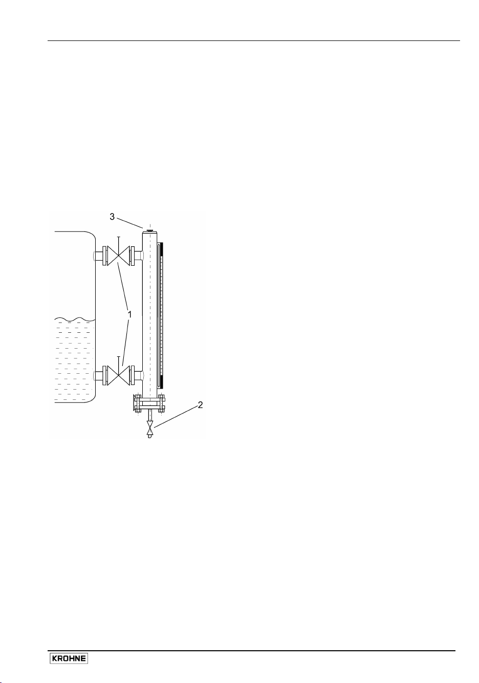
1.4 Mounting on the tank
• The BM 26 A bypass level indicator must be installed vertically on the tank
• When installing the BM 26 A bypass level indicator with or without the electrical level transducer
system, make sure that any magnetic fields generated by other equipment will not affect
measurements.
• Select bolts and gaskets (supplied by customer) that correspond to the pressure rating of the
connecting flange and the operating pressure.
• The process connections (flanges) must fit perfectly, i.e. they must be centred, parallel and
bolted in a professional way, in order to avoid unnecessary mechanical stress on the installation.
• The tank must be free of contaminants. It is recommended to install shut-off elements, e.g.
cocks, valves, etc., between the tank and bypass level indicator to allow the bypass level
indicator to be cleaned independently of the tank. The drain plug in the bottom flange must also
be replaced by a drainage cock with discharge line.
1
Shut-off valve (top and bottom)
2
Drainage valve with discharge tube.
3
Vent plug
Installation and Operating Instructions BM 26 A 13
Page 14
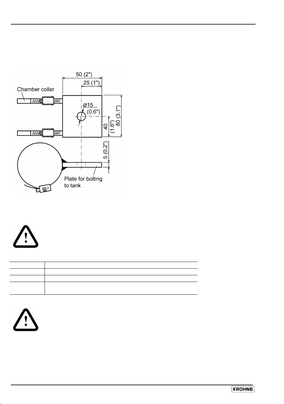
• Additional anchoring points between the BM 26 A and the tank are recommended for very high
installations (above 6 metres length for stainless steel). The standard anchor is a set of collars
welded to a plate. This is available on demand from KROHNE. See figure below for side and
plan view and dimensions in millimetres (inches).
1.5 Start-up procedure
WARNING
Take the necessary safety precautions when working with
pressurized tanks.
Step Action
1 Close drainage plugs and/or drainage cock .
2 Open shutoff elements at lower and upper connecting flange.
3 Adjust the position of the local measuring scale so that scale
level corresponds exactly to true level, see section 1.6.
WARNING
• The user must take the necessary steps to protect the installed instrument from
shock waves (water hammer). A pressure limiting valve must equally protect the
installation.
• The instrument must regularly undergo servicing to conform to the rules and
regulations applicable to the site that it is installed on.
• High Temperature versions - precautions must be taken to avoid burns to
operators.
14 Installation and Operating Instructions BM 26 A
Page 15
1.6 True level indication
1.6.1 Level measurement using the local indicator and scale
The float is equipped with a ring system of permanent magnets for transmission of liquid level to the
indicator. The indicator is linked magnetically to the magnet system in the float.
For design reasons, the minimum level in the measuring tube is given by the lower lateral flange
connection axis i.e. liquid level zero is the centreline of the lower connecting flange. As can be seen
in the diagram of the float and indicator in section 1.2, the bar follows the float below the liquid level.
There is a difference between true liquid level and the indicator position because:
• the float is immersed to a certain depth depending on the product density and float type,
• the float magnets are positioned below the float centreline in order for the float to have good
stability.
The scale is delivered correctly set up for measuring the product specified in the order. The red
reference mark at the top of the measuring tube (item 1 in the diagram below) shows where the top
of the scale must be clamped for the indicator to give an accurate reading of liquid level. No further
adjustment is necessary when the gauge is commissioned.
Note
If there is a large change in product density, a product other than the one specified in the order is
measured or a different float is installed, the scale on the BM 26 A may require adjusting to give an
accurate reading. Contact KROHNE for assistance (see also section 1.6.4 to correct the scale’s
position).
1 Reference mark : the top of the upper red
KROHNE plate must touch the bottom point
of the triangle
2 Scale
3 Measuring tube (containing float)
4 Top clamping collar ( scale-measuring tube)
Installation and Operating Instructions BM 26 A 15
Page 16
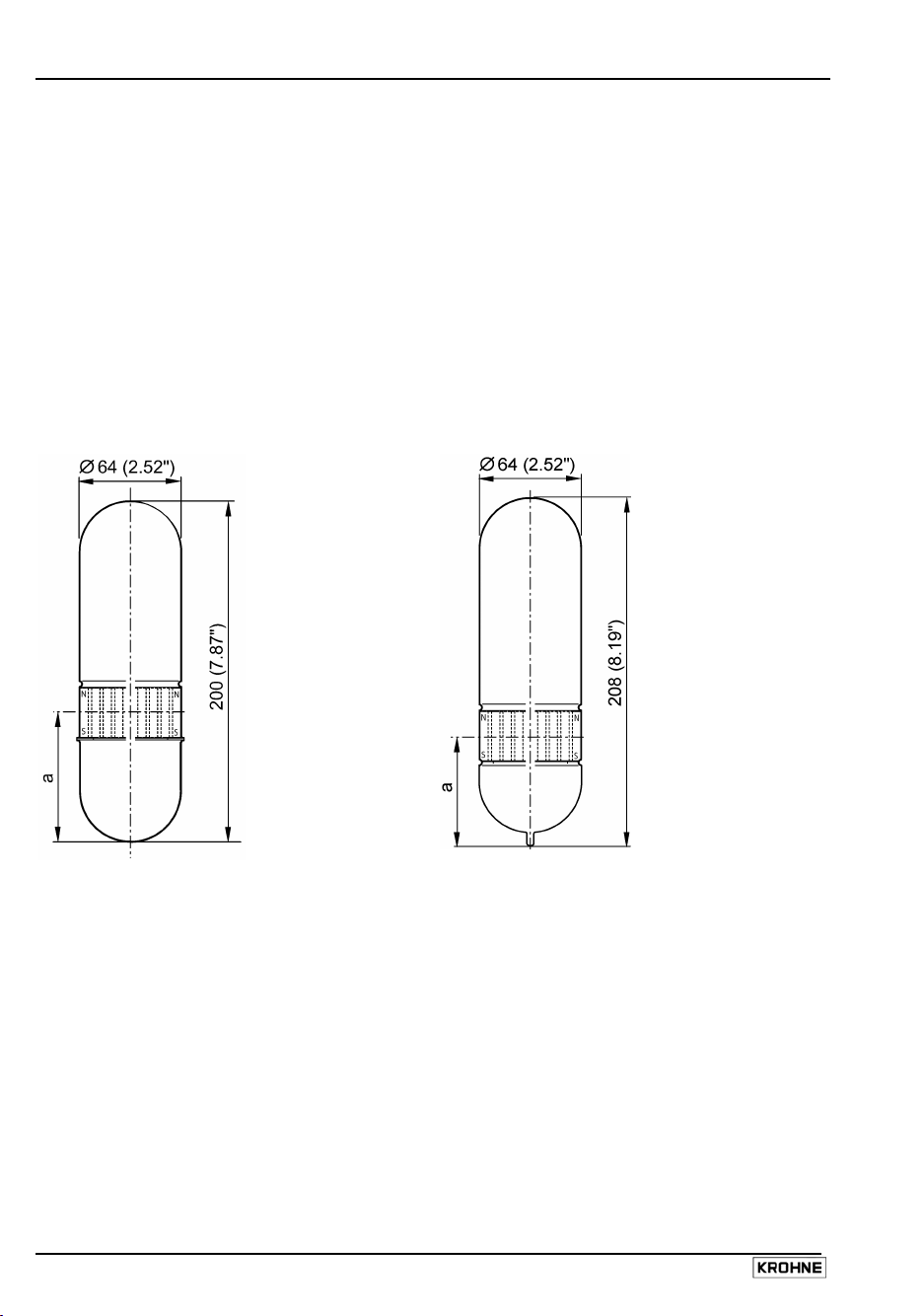
1.6.2 Floats
Four float types are used for liquid level measurement.
• Floats 1 and 2 are made of either 316L or 316Ti (as ordered).
• Floats 3 and 4 are made of titanium
The float number identifies the wall thickness of the float and the material used.
The dimension “a” in the diagrams below gives the distance from the base of the float to the centre
line of the integrated magnet system. This should be used in calculations for adjustments to the
measuring scale caused by differences between true liquid-level zero and indicated scale zero (see
section 1.6.4).
316L or 316Ti floats-No.1 and 2 Titanium floats-No. 3 and 4
where a = 47 mm or 1.85“ where a = 48 mm or 1.89“
and :
Float No.1 wall thickness = 1mm or 0.04”
Float No.2 wall thickness = 0.5mm or 0.02”
Dimensions in mm (inches)
Note
Minor variants of the above exist for particular applications: very low density products, interface
measurement applications and so on. Contact KROHNE for further information.
and :
Float No.3 wall thickness = 0.6mm or 0.024”
Float No.4 wall thickness = 1mm or 0.04”
16 Installation and Operating Instructions BM 26 A
Page 17
Density and operating temperature limits
Float
type
No. Min. density of product Product temperature
Min. Max.
kg/l lbs/
BM 26 A / Standard versions without approvals
1 0.82 51.19 – 200 – 325 300 570
2 0.55 34.34 – 200 – 325 300 570
3 0.50 31.21 – 200 – 325 300 570
4 0.60 37.46 – 200 – 325 300 570
Instruments or approved for use in Ex hazardous zones
BM 26 A / ATEX (local indicator with electrical equipment)
1 0.82 51.19 – 40 – 40 70 … 195* 160…380*
2 0.55 34.34 – 40 – 40 70 … 195* 160…380*
3 0.50 31.21 – 40 – 40 70 … 195* 160…380*
4 0.60 37.46 – 40 – 40 70 … 195* 160…380*
* The product temperature depends on the BM 26 A ATEX temperature class (T3 … T6). See
section 7.1 for further information.
Operating pressure limits
Float type
BM 26 A
No. Max. allowable operating pressure
At 20°C / 70°F At 100°C / 210°F At 200°C / 390°F At 300°C / 570°F
bar psig bar psig bar psig bar psig
Standard versions without approvals
1 55 800 41 600 37 535 32 465
2 23 335 12 175 10 145 9 130
3 23 335 13 190 10 145 8 115
4 55 800 31 450 24 350 19 275
Instruments approved for use in Zone 0
BM 26 A/ATEX (local indicator with electrical equipment)
1 55 800 41 600 – – – –
2 23 335 12 175 – – – –
3 23 335 13 190 – – – –
4 55 800 31 450 – – – –
Important note
Float test pressure is tested according to pressure equipment directive 97/23/EC and official
approvals.
Density and operating temperature limits
3
ft
Operating pressure limits of the float
°C °F °C °F
Installation and Operating Instructions BM 26 A 17
Page 18
1.6.3 Changing the process conditions
If the user wishes to use the BM 26 A to measure another product, then the following points should
be noted:
• Contact KROHNE for advice and information on equipment / product compatibility especially
where use in hazardous areas is concerned.
• Ensure that Pressure Equipment Directive 97/23/EC is observed, if relevant.
• The depth of immersion “c” (see section 1.6.4) of the float increases as product density
decreases. This depth is also dependent on the float model (No. 1, 2, 3 or 4) and material used
(316L, 316Ti or titanium). The new depth of immersion “c” is shown on the two line graphs
below. Further information is available from KROHNE on request to accurately calibrate your
instrument. When contacting KROHNE remember to:
− quote KROHNE references (order / fabrication no.) for the BM 26 A in question
− identify the new product and give its density at the new operating conditions.
− give information about the old application. Floats may have been especially adapted
for specific applications; for example: density- adjusted (pressurized) or floats for low
density applications and floats with ballast for interface measurement.
• The top of the float must be no more than 35mm or 1.38” above the product surface to ensure
reliable floatability and accurate measurement.
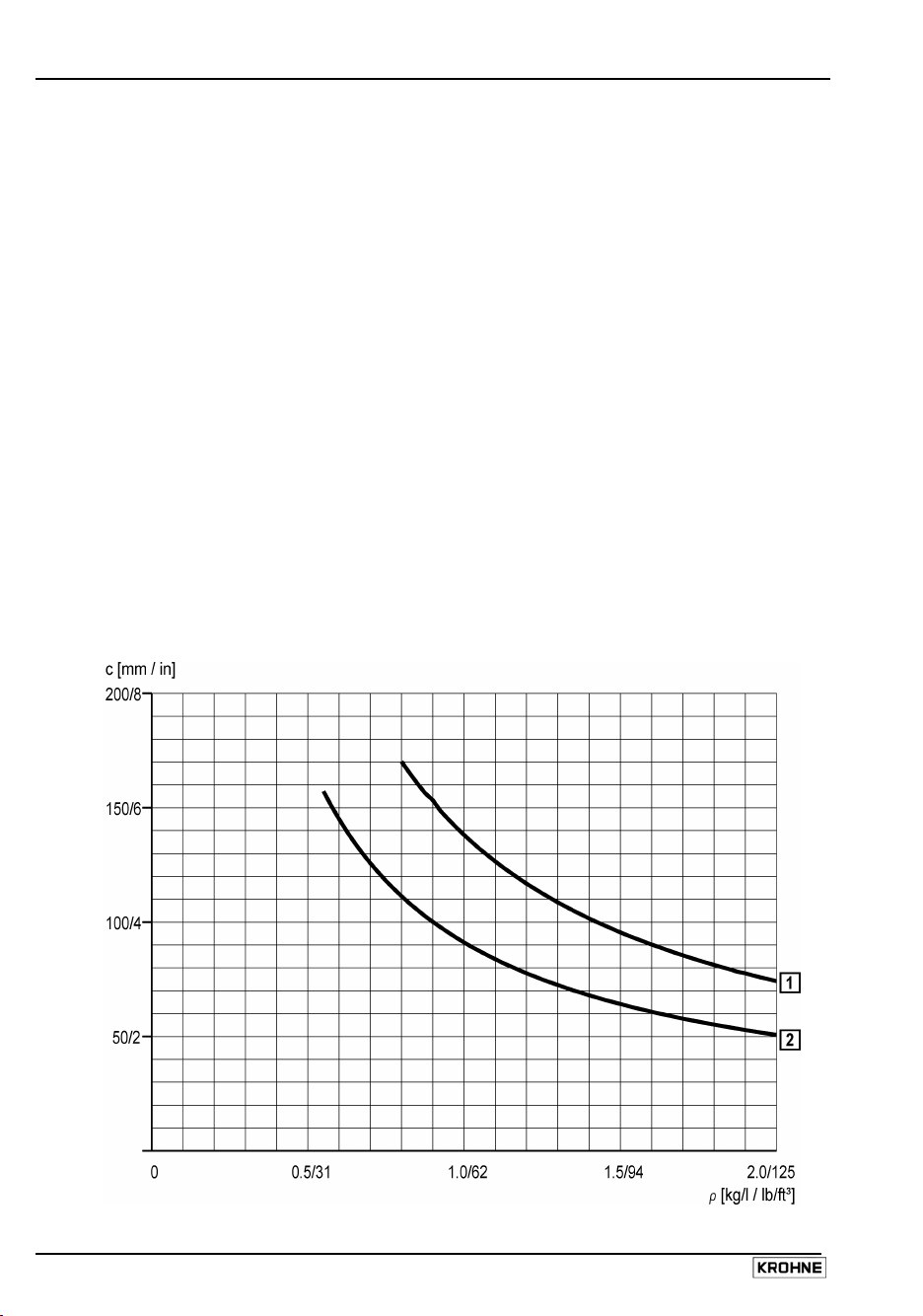
Graph 1: Float immersion depth against product density
Line 1 : Float no. 1 made of 316Ti (1.4571) or 316L (1.4404), wall thickness 1mm or 0.04”
Line 2 : Float no. 2 made of 316Ti (1.4571) or 316L (1.4404), wall thickness 0.6 mm or 0.02”
Where c is immersion depth and ρ is product density
18 Installation and Operating Instructions BM 26 A
Page 19
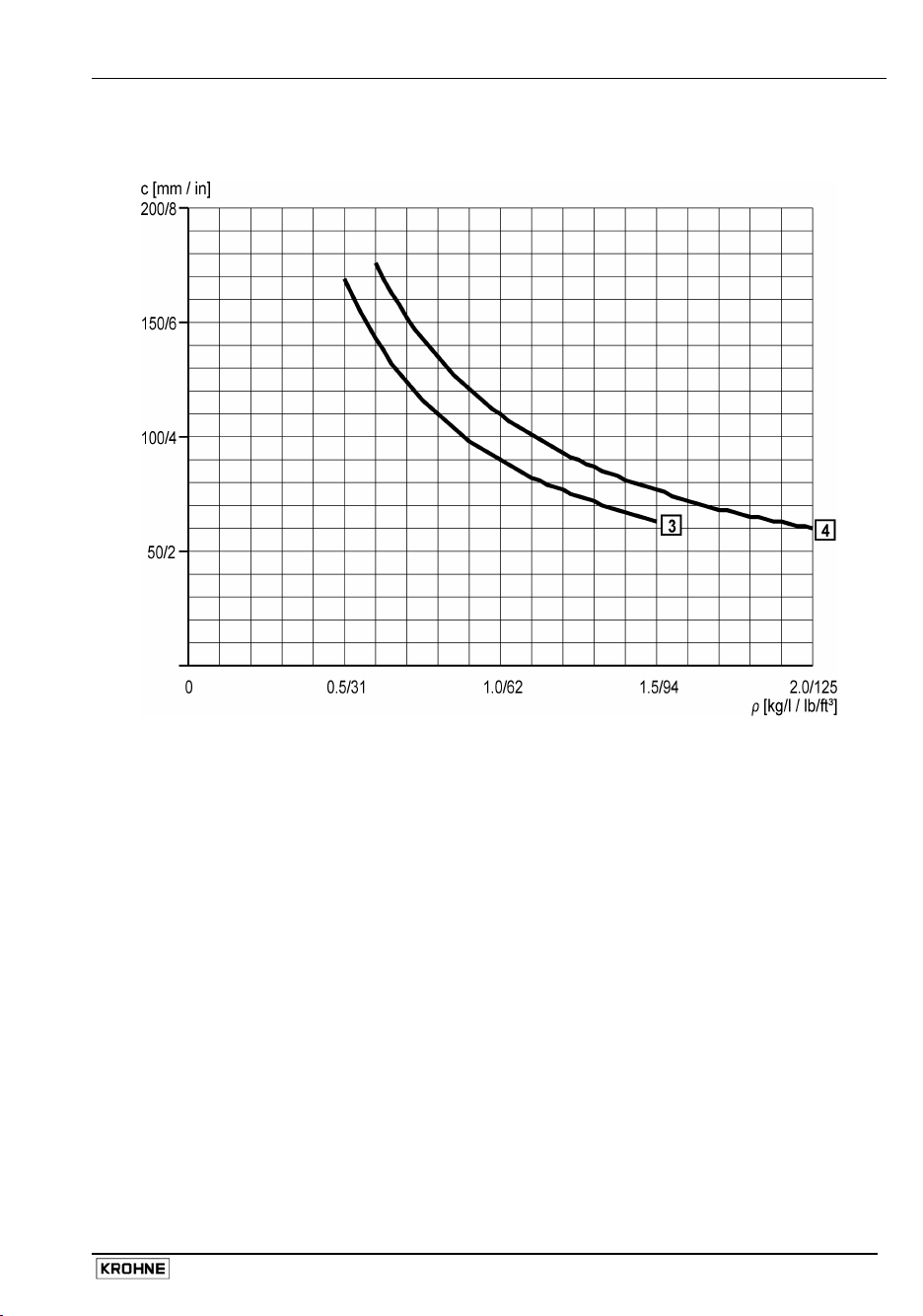
Graph 2: Float immersion depth against product density
Line 3 : Float no. 3 made of titanium, wall thickness 0.6 mm or 0.024”
Line 4 : Float no. 4 made of titanium, wall thickness 1 mm or 0.04”
Where c is immersion depth and ρ is product density
Installation and Operating Instructions BM 26 A 19
Page 20
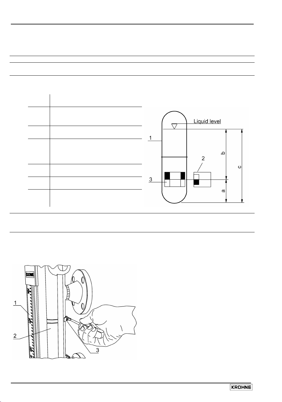
1.6.4 Correcting the scale position to accurately read true liquid level
The scale* can be corrected by the customer using the following procedure:
Step Action
1 Find the float immersion depth “c” (supplied by KROHNE, refer also to section 1.6.3).
2 Subtract the dimension “a”, float base to magnet centreline (given on the float dimensioned
drawing in Section 1.6.2), from “c” to get the dimension “b”, scale correction factor.
b = c – a (difference between liquid level
c = float immersion depth (a function of
a = distance from centerline of magnet
1 = Float
2 = Follower magnet of indicator (or limit
3 = Position of magnets mounted in the
3 Loosen the two clamp collars holding the measuring scale onto the measuring tube using a
4 Bring the zero point (top of the lower red KROHNE plate) on the scale into line with the
4a Undo top collar
*This information also applies to the initial setting up of limit switches – however, the fitter should
also remember to take into account the limit switches offset trigger point (see section 3.6).
Item Description
and indicator position due to product
density)
product density), see section 1.6.3.
system to the float base, see
dimensioned float drawings in
section 1.6.2.
switch)
float
screwdriver or 8 mm wrench.
centreline of the bottom lateral process connection.
1 Measuring scale
2 Measuring tube
3 Top measuring scale collar
20 Installation and Operating Instructions BM 26 A
Page 21
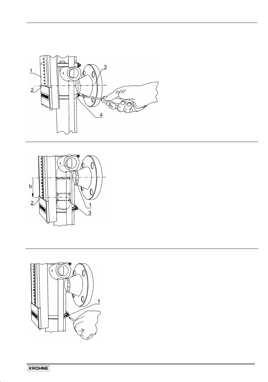
4b Undo bottom collar
4c Zero the scale (default)
1 Measuring scale
2 Bottom of scale (item 1) indicated
by top of red KROHNE plate.
Default position is on the same level
as item 3.
3 Centreline of bottom lateral process
connection.
4 Bottom measuring scale clamp
5 Move the measuring scale down the measuring tube to set to by “b” mm.
1 Centreline of bottom lateral process
connection.
2 Bottom of scale (item 1) indicated
by top of red KROHNE plate.
3 Position of float (dashed lines)
when measuring tube filled up to
the centre line of bottom lateral
process connection.
6 Retighten the two collars holding the measuring scale onto the measuring tube.
B Move scale down measuring tube
by “b” mm. The bottom of the scale
will then be at the same level as the
magnets in the float
1 Measuring scale collar screw
Installation and Operating Instructions BM 26 A 21
Page 22

1.6.5 Functional check of local level display (bar indicator only)
Step Action Comments
1 Break the magnetic bond between the
float and the indicator bar using a bar
magnet.
2 Retrieve the indicator the bottom of the
tube with a bar magnet. Lift up the tube.
3 End of the procedure. If the indicator bar fails to bond
*See diagram in section 1.2.
The indicator bar (9*) will drop down and
disappear behind the red cover (12*) on
the front scale.
The indicator will again magnetically bond
with the float at the correct indicated value.
magnetically, please contact KROHNE for
assistance.
22 Installation and Operating Instructions BM 26 A
Page 23

2 Level transducer
2.1 General notes
In addition to the local scale indicator, the BM 26 A can be fitted with a level transducer that
transmits a magnetically-actuated 4 to 20 mA analogue current output for monitoring level outside a
hazardous zone.
This type of indication uses a stainless steel tube containing a resistive reed contact chain that is
clamped adjacent to the measuring tube. The position of the float magnet in the measuring tube
determines the output. This output is calibrated at the factory and does not require any further
adjustment when the BM 26 A is commissioned.
The transducer reading is converted into a current output of 4 to 20 mA by the transmitter that is
potted into the transducer housing. The transmitter module used is detailed in the following subsection (detailed technical data is given in section 7.2). The intrinsically safe transmitter may be
used with or without a galvanically-isolated 4 to 20 mA output for the BM 26 A Eex ia version.
BM 26 A Std/ EEx i/EEx d with level transducer (aluminium transmitter housing)
1 Cable entry.
Only Ex i or Ex d-certified
components and cable entry
fittings to be connected!
With M20 x 1.5 thread.
Optional: M25 x 1.5
NPT¾
2 Level transducer housing
3 Stainless steel tube-encased
reed chain
4 BM 26 A measuring tube and
scale with magnetic following
level-indicator
5 PE Ground terminals.
Both terminals must be
connected to Ground!
Dimensions in mm and (inches)
Installation and Operating Instructions BM 26 A 23
Page 24

2.2 Transmitters
The BM 26 A can be equipped with a level transducer. The level transducer is defined by the type of
communication used (ER – electronic remote), housing protection (Ex d, Ex I etc.), housing material
(AL – aluminium) and transmitter module.
2.2.1 Transmitter versions for the BM 26 A
Version designation Housing protection Transmitter module
ER/STD/AL/D Without (non-Ex)
ER/EXI/AL/D EXI (EEx ia)
ER/EXD/AL/D EXD (EExd )
ER/STD/AL/E Without (non-Ex)
ER/EXI/AL/E EXI (EEx ia)
ER/EXD/AL/E EXD (EEx d)
ER/STD/AL/F Without (non-Ex)
ER/EXI/AL/F EXI (EEx ia)
ER/EXD/AL/F EXD (EEx d)
2.2.2 Electrical connections
WARNING
Do not remove the transducer cover until the power supply
has been disconnected
PR 5343B : 4-20mA (top view)
D PR 5343B
4-20mA
E PR 5350B
PROFIBUS PA / FF
F PR 5335B
4-20mA+HART
24 Installation and Operating Instructions BM 26 A
Page 25

PR 5350B : PROFIBUS PA / FF
PR 5335B : 4-20mA+HART
WARNING
Refer to section 7.2 for technical information on the use of equipment in hazardous
locations.
®
Installation and Operating Instructions BM 26 A 25
Page 26

3 Limit switches / contacts
3.1 General notes
To signal specific liquid levels, the BM 26 A bypass level indicator can be equipped with 13 different
types of limit switch that are clamped to the measuring tube and are adjustable over the whole
measuring range. They are actuated by a magnet incorporated into the float. The operating
conditions define which limit switches may be used. Refer to section 7.3 for detailed technical data
on each type of limit switch.
The limit switches are delivered separate from the BM 26 A gauge and have to be mounted on site.
See sections 3.5 to 3.6 for installation instructions.
3.2 Designation code for defining limit switch versions
Housing
protection
STD (Without) LC (Low power
EXI (EEx ia)
EXD (EEx d)
3.3 Limit switch options for the BM 26 A (non-Ex)
Designation Housing
MS20/STD/L
C/PC/NN/BT
MS15/STD/L
C/PC/NO/BT
MS15/STD/L
C/AL/NN/HT
MS15/STD/L
C/AL/NO/HT
MS15/STD/H
C/PC/NN/BT
MS15/STD/H
C/AL/NN/HT
Cut-out
power
Housing
material
NAMUR
conformity
Process
temperature
applications
PC (Polycarbonate /
cut-out)
HC (High power
Standard)
AL (Aluminium) NO (NAMUR) HT (High
cut-out)
protection
Housing
material
Power cut-out Process temperature Ambient
Without PC 30VA
<250°C <480°F -20...+120 -5...+245
NN (NonNAMUR)
temperature
/ °C
BT (Low
temperature)
temperature)
Ambient
temperature
/ °F
0.5A
230V AC
Without PC NAMUR <250°C <480°F -20...+120 -5...+245
Without ALU 20VA
<300°C <570°F -20...+120 -5...+245
1.5A
250V AC
Without ALU NAMUR <300°C <570°F -20...+120 -5...+245
Without PC Max.: 100VA
<250°C <480°F -20...+120 -5...+245
Min.: 3VA
1.5 A
250V AC
Without ALU Max.: 100VA
<300°C <570°F -20...+120 -5...+245
Min.: 3VA
1.5A
250V AC
26 Installation and Operating Instructions BM 26 A
Page 27

3.4 Limit switch options for the BM 26 A (ATEX version)
Designation Housing
MS20/EXI/LC/
protection
EXI* PC 0.5A* ** ** Ui
PC/NN/BT
MS15/EXI/LC/
EXI* PC NAMUR ** ** Ui
PC/NO/BT
MS15/EXI/
EXI* ALU 1.5A* ** ** Ui
LC/AL/NN/HT
MS15/EXI/
EXI* ALU NAMUR ** ** Ui
LC/AL/NO/HT
MS15/EXD/LC/A
EXD ALU 20VA
L/NN/HT
MS15/EXD/LC/A
EXD ALU NAMUR ** ** U
L/NO/HT
MS15/EXD/HC/A
EXD ALU Max.:*****
L/NN/HT
* To be connected to a certified intrinsically-safe power supply only.
** Dependant on ATEX temperature class. Refer to section 7.1 for further information.
*** The current value is not imposed, however the power supply must be intrinsically-safe.
**** The voltage value is not defined, however the power supply must be intrinsically-safe.
3.5 How to use a limit switch
3.5.1 Operating principle
The MS 15/STD, MS 15/EXI, MS 15/EXD, MS 20/STD and MS 20/EXI limit switches consist of a
reed contact that is actuated directly by the magnet system in the float. Due to their bi-stable
switching characteristic, the switching state is maintained until the float magnet system again
deactivates the limit switch in the opposite direction. Line-side connection of a suitable isolation
switching amplifier is recommended.
3.5.2 Installation
1 Attach the switch to the measuring tube at the desired level using the metal collar supplied.
2 Adjust the switch level to take into account the difference between indicated level and true level
(see section 1.6.4).
3 Adjust the switch level to take into account limit switch trigger point offset (see section 3.6.2).
Note:
Due to its bi-stable characteristic, the switch can be operated in open-circuit or closedcircuit mode (see section 3.5.5 Electrical connections), when appropriately connected.
Housing
material
Power
cut-out
1.5A
250V AC
Min.: 3 VA
1.5 A
250 V AC
Process
temperature
Ambient
temperature
** ** U
** ** U
Power supply
characteristics
****
I
100mA
i
C
0
i
L
0
i
24V
***
I
i
C
0
i
0
L
i
****
500mA
I
i
C
0
i
L
i
24V
I
***
i
C
0
i
L
0
i
380VAC
max
I
1,5 A
max
P
20 VA
max
380VAC
max
1,5 A
I
max
P
20 VA
max
380VAC
max
1,5 A
I
max
P
20 VA
max
Installation and Operating Instructions BM 26 A 27
Page 28

Clamping in position on measuring tube
MS 15 /STD/…/PC/…/BT or MS 15/EXI/…/PC/…/BT
MS 15/STD/…/AL/…/HT, MS 15/EXD/…/AL/…/HT, or MS 15/EXI/…/AL/…/HT
1 Limit switch clamp
2 Limit switch bracket
3 Measuring scale
4 Measuring tube
5 2 M4 screws (for
6 Switching point
7 MS 15 /STD or /EXI
1 1 x locking screws M6
2 Limit switch
3 Limit switch clamp
clamp
bracket)
centerline
Fine adjustment:
See procedure,
section 3.6
limit switch cover
-use 3 mm Allen key
bracket
4 Measuring tube
5 Measuring scale
clamp
6 Switching point
centerline
Fine adjustment:
See procedure,
section 3.6
7 Cover lock:
M3 screw -
use 2mm Allen key
8 MS15 EXD
28 Installation and Operating Instructions BM 26 A
limit switch cover
9 Cable fitting (not
supplied by KROHNE)
Page 29

MS 20 /STD or /EXI
1 Limit switch clamp (switch
has an integral bracket)
2 Measuring scale clamp
3 Measuring tube
4 Switching point centerline
Fine adjustment:
See procedure, section 3.6
5 MS20 /STD or /EXI
limit switch cover
3.5.3 Overall dimensions of limit switches mounted on measuring tube
MS 15/STD/…/PC/…/BT and
MS 15/EXI/…/PC/…/BT
* Item 1: limit switch collar screw
MS 20/STD and MS 20/EXI
MS 15/STD/…/AL/…/HT,
MS 15/EXI/…/AL/…/HT, and /EXD/…/AL/…/HT
1 Metal clamping collar screw
2 MS 20 limit switch
3 Measuring tube
Dimensions in mm (inches)
Installation and Operating Instructions BM 26 A 29
Page 30

3.5.4 Limit switch dimensions (without bracket and clamp)
MS 15/STD/…/PC/…/BT
and /EXI/STD/…/PC/…/BT
with PG13.5 fitting
Side view Side view
MS 15/STD/…/AL/…/HT,
MS 15/EXI/…/AL/…/HT,
and MS 15/EXD/…/AL/…/HT
without cable fitting (supplied by customer)
Top view
MS 20/STD and /EXI with PG9 fitting and integrated bracket
Side view
Dimensions in mm (inches)
30 Installation and Operating Instructions BM 26 A
Page 31

3.5.5 Electrical connections
Unscrew the housing cover at the rear. For further technical data, see Section 7.3. Use connections
that are certified for Exd applications for EXD casings. Wire as shown below:
WARNING
Do not remove the limit switch cover until the power supply has been disconnected
MS 15 limit switches
STD/…/PC/…/BT or EXI/…/PC/…/BT terminals
1 Terminals
2 Cable entry fitting
STD/…/AL/…/HT, EXI/…AL/…/HT, or EXD/…/AL/…/HT terminals
1 Terminals
2 Hole with M20 x 1.5
PG 13.5
thread. Cable fitting
supplied by customer
Installation and Operating Instructions BM 26 A 31
Page 32

STD/…/PC/NO/BT or EXI/…/PC/NO/BT (NAMUR) terminals
1 Terminals
2 Cable entry fitting
PG 13.5
MS 20 limit switches
STD and EXI terminals
1 Cable entry fitting PG9
2 Terminal block
3 Blue wire (terminal 1)
4 Black wire (terminal 3)
5 Brown wire (terminal 2)
32 Installation and Operating Instructions BM 26 A
Page 33

3.6 Fine adjustments to the limit switch trigger point
3.6.1 General notes
Due to the way the reed switch switches from one state to another and the geometry of magnets
integrated into the float, different switching points are obtained when the float moves up or down.
This must be taken into account when positioning the limit switch.
The assembler must equally remember that as with the local display, limit switch position must take
into account the fact that indicated level is lower than true level.
By default, indicated level is lower than true level by “b” mm. This should be adjusted during
commissioning (see section 1.6.4). When the float moves up, the switch is triggered with the float
offset by “d” mm. When the float moves down, the switch is triggered with the float offset by “e” mm
(see section 3.6.3).
Hysteresis: see section 7.3.
3.6.2 Fine adjustments to the limit switch trigger point
Step Action
1 Choose the true level at which the limit switch should signal “limit reached“.
2 Adjust the switch position using the procedure in Section 1.6.4 to take into account the
difference between true liquid level and indicated level (magnet position). Move switch down
measuring tube by “b” mm.
3 Refer to the table in section 3.6.3: “Switching point offsets“. Find the limit switch offset based
on the limit switch type and the direction in which the float is moving for the switch to be
triggered. Example: if the switch has to trigger when the float moves upwards then a MS
15/STD switch needs to be moved down the measuring tube by 5mm or 0.2 ”.
4 Loosen the collar holding the limit switch onto the measuring tube.
5 Now re-position again to take into account the switch trigger points -Move the switch up or
down the measuring tube by the amount required for the offset as indicated in the table and
drawing in section 3.6.3.
6 Retighten the collar holding the limit switch onto the indicator tube.
Installation and Operating Instructions BM 26 A 33
Page 34

3.6.3 Switching point diagram and offset values for limit switches
Item Description
0 zero scale mark
b difference between liquid level and scale reading due to product density
L level indication (limit value) on the scale
d trigger point offset of limit switch when the float goes up (distance between contact
centreline and level indication or limit value - see table below)
e trigger point offset of limit switch when the float goes down (distance between contact
centreline and level indication or limit value)
Switching point offsets
Offset due to direction of
float displacement
Limit switch d (Up) e (Down)
mm inch mm inch
MS 15/STD
MS 15/EXI
MS 15/EXD
MS 20/STD
MS 20/EXI
– 5
– 5
– 0.2
– 0.2 – 5
– 5
– 0.2
– 0.2
Dimensions in mm (inches)
34 Installation and Operating Instructions BM 26 A
Page 35

4 Special versions
4.1 Low-temperature versions AG, TR or IC/TR
Version BM 26 A/AG: to -40°C or -40°F
Version BM 26 A/TR: to -200°C or -330°F
Version BM 26 A/IC/TR: to -200°C or -330°F
All components are made of solid CrNi steel grade 316 Ti (equivalent to 1.4571) or 316 L (equivalent
to 1.4404). The measuring tube in the BM 26 A/IC/TR has glass wool insulation and aluminium
cladding. The float magnets are made of a special material.
The scale indication is magnified by plexitherm glass for easier reading. The ambient temperature
and product temperature will have been specified by the customer to ensure insulation is
appropriate. The socket length to the connecting flange will have been specified by the customer if
insulation is supplied by the customer.
Version AG Version TR Version IC/TR
1 Plexitherm glass 1 Measuring tube 1 Measuring tube
2 Indicator scale 2 Indicating tube with indicator 2 Insulation (lagging)
3 Indicating tube with indicator 3 Plexitherm glass 3 Indicating tube with indicator
4 Measuring tube 4 Insulation 4 Plexitherm glass
5 Aluminium cladding
Dimensions in mm (inches)
4.2 High-temperature versions HR or IC/HR
The BM 26 A/HR and BM 26 A/IC/HR versions are suitable for applications in the range from
200°C or 390 °F to 300°C or 570°F. All components are made of solid stainless CrNi steel. The
measuring tube in the BM 26 A/IC/HR version has glass wool insulation and aluminium cladding.
1 Measuring tube
2 Insulation (lagging)
3 Indicating tube with indicator
4 Aluminium cladding
Installation and Operating Instructions BM 26 A 35
Page 36

4.3 Heating system for measuring tube BM 26 A/B
For extreme operating conditions, the measuring tube is fitted with a heating jacket with 2 standard
Ermeto 12 connections, for heat transfer fluid or steam heating. See section 7.1 for more technical
data.
The maximum allowable operating pressure, Pmax, of the heating medium depends on the length of
the measuring chamber.
Measuring chamber length, L Pmax*
m ft bar psig
0 < L ≤ 2 0 < L ≤ 6.5 10 145
2 < L ≤ 4 6.5 < L ≤ 13 7 101.5
4 < L ≤ 6 13 < L ≤ 19.5 5 72.5
* The heating steam or cooling fluid must have a temperature in the range of -200°C to +400°C /
-330°F to 750°F. Insulation of the measuring tube is recommended.
If operating conditions outside the ranges above are necessary, please contact KROHNE.
1. Heating medium inlet
2. Heating system
3. Measuring tube
4.4 Liquid/liquid interface measurement BM 26 A/TS
If a tank contains two liquids with different densities, the level of the interface can be measured
by means of an adapted float loaded with ballast. The floats buoyancy properties permit it to float on
the surface of the heavier liquid and ignore the lighter liquid. The difference in liquid densities must
be at least 100 g/l or 6.24 lb/ft
3
, with the float being fully submerged in the lighter liquid.
36 Installation and Operating Instructions BM 26 A
Page 37

5 Maintenance
The instrument will not normally require any maintenance. However, flushing the instrument is
recommended from time to time if the tank product is contaminated or has a tendency to form
deposits. In order to do this, open the drain plug or drain valve and flush out. If the float also requires
cleaning, remove it from the bottom of the measuring tube after first closing off the shut-off
elements.
WARNING
Follow accident prevention regulations carefully when working with pressurized tanks
and dangerous chemical products
6 Ordering spare parts
The following details are required for ordering spares:
1. Commission number of the level gauge (see instrument nameplate)
2. Instrument type, model, description, nominal size of process connections (DN)
3. Construction materials
Note:
Please specify flange spacing (measuring range ie. the distance between the process
connections axes) or the KROHNE Comm. No. from the initial order.
Installation and Operating Instructions BM 26 A 37
Page 38

7 Technical data
7.1 Technical data: BM 26 A
Instrument type BM 26 A
Measuring range
Standard 0.3 … 6 m / 1 … 20 ft
Accuracy
Min. product density
Viscosity
Max. allowable operating
pressure at 20°C / 70°F*
Indicator
Standard linear indicator with cm/m graduation
Optional linear scale with inch/feet, % or volume
graduation, as required; flap indicator without
Mounting position
Protection (indicator) to EN 60529
Pressure vessel approvals
Electromagnetic compatibility (EMC)
Process temperature
Standard, with flap or bar indicator -40°C…+200°C or -40…+390°F
Optional, non- Ex -200°C … +300°C / -325 … +570°F *,**
Other approvals
ATEX
INERIS 02ATEX0088 X
ATEX applications: special conditions for safe use
BM 26 A Bypass Level Indicator for all options
Temperature class*** Process temperature Ambient temperature range
T6 T(fluid) <= 70°C / 158°F -40 to +60°C / -40 to +140°F
T5 T(fluid) <= 95°C / 203°F -40 to +50°C / -40 to +122°F
T4 T(fluid) <= 130°C / 266°F -40 to +50°C / -40 to +122°F
T3 T(fluid) <= 195°C / 383°F -40 to +40°C / -40 to +104°F
* dependent on material, flange pressure rating and float pressure resistance
** higher on request
*** the temperature category of the BM 26 A depends on the options fitted to the
indicator, the ambient temperature and the process temperature
± 10 mm / ± 0.4” of measured value
0.5 kg/l … 3.0 kg/l / 31.2 … 187 lb/ft
≤ 5000 mPa.s / 3.360 lb/ft.s
40 bar / 580 psig (information on higher
pressure levels available on request)
scale; flap indicator with scale in cm/m,
inch/feet, % or volume graduation, as required
vertical
IP 68 (equivalent to NEMA 6)
Pressure equipment directive 97/23/EC.
to EN 50081-1, EN 50082-2 & EN61326 (1+2)
ATEX II 1/2 G or ATEX II 1 G
EEx d ia IIC T3 … T6 or EEx d IIC T3 … T6 ;
EEx ia IIC T3 … T6
3
38 Installation and Operating Instructions BM 26 A
Page 39

Connecting flanges
to DIN 2501:
Standard DN 25, PN 40 Form B1 (EN 1092-1)
Option DN 15 to DN 50, PN 16 or PN 40
to ASME B 16.5:
for the heating jacket
Connecting tube (standard) For Ermeto 12 screw joint
to DIN 2501 DN 15, PN 40
to ASME B 16.5 ½”, 150LB/RF or 300LB/RF
Pipe 12 x 1 mm (0.47” x 0.04”)
Information on other standards and pressure ratings supplied on request
Materials (BM 26 A without options)
Level transducer (reed chain)
see section 7.2 for technical data on
½” to 2”, ASME150LB/RF or 300LB/RF
Stainless steel 316 L or Ti
current output 4 … 20 mA
current output 4 … 20 mA + HART
output PROFIBUS PA/FF
transmitter module options
Installation and Operating Instructions BM 26 A 39
Page 40

7.2 Technical data: level transmitter modules
Name PRETOP 5343B PR 5350B PR 5335B
Description
4 … 20mA. Conversion of
resistance variation to
analogue current signals.
PROFIBUS PA or FF.
Conversion of resistance
variation.
4-20mA+HART
Conversion of resistance
variation to analogue
current signals.
Connection of up to 15
transmitters to a digital 2wire signal with HART
communication.
4 … 20 mA
(limits : 3.5 & 23 mA) and
HART® protocol (loop link)
Output
4 … 20 mA
(limits : 3.5 & 23 mA)
PROFIBUS
®
PA protocol
Profile A&B, ver. 3.0 (EN
50170 vol.2) or
FOUNDATION™
Fieldbus protocol
Max. load RL
Measuring
error
Power supply
Ambient
temperature
(U – 8)
0.023
8 … 35Vdc
8 … 30Vdc (ATEX)
Refer to table in “ATEX applications: special conditions for safe use”, section 7.1
Ohms
- (U – 8) Ohms
0.023
± 10 mm
9 … 32Vdc
9 … 30Vdc (ATEX)
8 … 35Vdc
8 … 30Vdc (ATEX)
Approvals
Ex EEx ia, EEx d
Max power
dissipated by
Exd housing,
P
max
Max voltage
for Exd
housing, U
Max safety
5 W
36 V
max
values for Exi
applications
Terminal
block
28V
U
i
30 V
28V
Ii 120mA 120mA 120mA
Pi 0.84W 0.84W 0.84W
Ci 1nF 2nF 1nF
Li 10µH 1µH 10µH
®
.
40 Installation and Operating Instructions BM 26 A
Page 41

7.3 Technical data: limit switches
Limit switch MS 20/STD MS 20/EXI
Max. switching capacity
Ambient temperature
Process temperature
Protection category
to EN 60529
Cable entry
Max. safety values
Housing material
Hysteresis
Weight
Limit switch MS 15/STD MS 15/EXI MS 15/EXD MS15/*/NAMUR
max. switching capacity
LC (low power cut-out)
max. switching capacity
HC (high power cut-out)
Ambient temperature
Process temperature HT
(high)
Process temperature BT
(low)
Protection category
to EN 60529
Cable entry PC
AL
Max. safety values
Housing material BT
HT
Hysteresis
Weight PC
AL
* For these characteristics refer to the other columns in the table above for STD (i.e. non-Ex),
EXI or EXD switches – depending on which official approval has been selected.
** standard thread (fitting not supplied). Optional: M25 x 1.5 or NPT ¾.
*** Refer to table in “ATEX applications: special conditions for safe use”, section 7.1
**** The value is not defined, however the power supply must be intrinsically-safe
***** U
= 380 V CA, I
max
30 VA 0.5 A
0.5 A, 230 V AC
–20°C … 120°C
–4°F … 250°F
-20°C … +80°C
-4°F … 175°F (T6) or
-20°C … +95°C
-4°F … 200°F (T5)
< 250°C / < 480°F < 250°C / < 480°F
IP 65 IP 65
NEMA 4/4X NEMA 4/4X
PG 9 PG 9
- Ui= ****
Ii = 100 mA
Ci= 0 nF, Li= 0 µH
polycarbonate polycarbonate
0
0
85 g / 0.2 lb 85 g / 0.2 lb
20 VA 1.5 A According to
1.5 A, 250 V AC
20 VA
1.5 A
NAMUR 19234
250 V CA*****
Max. 100 VA
Min. 3VA
1.5 A
-
Min. 3 VA
1.5 A
250 V CA*****
*
250 VA
–20°C … 120°C *** *** *
–4°F … 250°F
< 250°C
*** *** *
< 480°F
< 300°C
*** *** *
< 570°F
IP 65 IP 65 IP 65 *
NEMA 4/4X NEMA 4/4X NEMA 4/4X
PG 13.5
M 20 x 1.5**
- Ui=****
Polycarbonate
Aluminium
0 0 0
130 g / 0.3 lb
1200 g / 2.6 lb
= 1,5 A, P
max
max
PG 13.5
M 20 x 1.5**
M 20 x 1.5**
***** *. For Exi :
Ii =500 mA
Ci=0nF,Li= 0µH
Polycarbonate
Aluminium
Aluminium
130 g / 0.3 lb
1200 g / 2.6 lb - 1200 g / 2.6 lb
= 20 VA
*
Ui=24V, Ii = ****,
Ci=0nF, Li= 0µF
*
*
*
Installation and Operating Instructions BM 26 A 41
Page 42
7.4 Guide tube assembly materials
Version Flange Gaskets Measuring tube
Material Diameter
mm inches
BM 26A 316Ti (1.4571)
316L (1.4404)
7.4.1 Maximum operating conditions for BM 26 A with 316 Ti steel measuring tube
according to European Union Pressure Equipment Directive 97/23/EC
The graph below shows the maximum allowable process pressure, Ps, for a given process
temperature, Ts, in a 316Ti measuring chamber of a given nominal diameter (the flanges being
grouped into 4 categories).
aramide
(PTFE optional)
316Ti (1.4571)
316L (1.4404)
72 x 2.3 2.83 x 0.091
Higher operating pressures may be approved by KROHNE following analysis of customer
specifications. Maximum product temperature is dependant on the application and is defined by the
customer in the product order options list.
7.4.2 Flange categories for operating conditions in a 316Ti steel measuring tube
Flange Categories
1 2 3 4
DN15 PN40 DN50 PN40 DN40 PN40 ½ " ASME 150LB
DN20 PN40 DN50 PN40 WN DN40 PN40 WN ¾ " ASME 150LB
DN25 PN40 2" ASME 300LB 1" ASME 150LB
DN15 PN40 WN 1"½ ASME 150LB
DN20 PN40 WN 2" ASME 150LB
DN25 PN40 WN
½ " ASME 300LB
¾ " ASME 300LB
1" ASME 300LB
1"½ ASME 300LB
42 Installation and Operating Instructions BM 26 A
Page 43

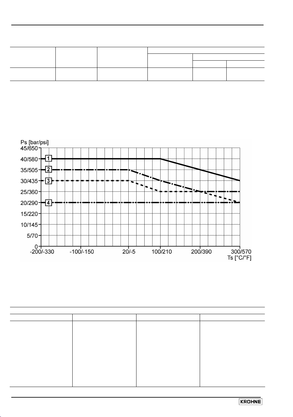
7.4.3 Maximum operating conditions for BM 26 A with 316 L steel measuring tube
according to European Union Pressure Equipment Directive 97/23/EC
The graph below shows the maximum allowable process pressure, Ps, for a given process
temperature, Ts, in a 316L measuring chamber of a given nominal diameter (the flanges being
grouped into 4 categories)
Higher operating pressures may be approved by KROHNE following analysis of customer
specifications. Maximum product temperature is dependant on the application and is defined by the
customer in the product order options list.
7.4.4 Flange categories for operating conditions in a 316L steel measuring tube
Flange Categories
1 2 3 4
DN15 PN40 DN25 PN40 DN40 PN40 ½ " ASME 150LB
DN20 PN40 DN25 PN40 WN DN40 PN40 WN ¾ " ASME 150LB
DN15 PN40 WN 1" ASME 300LB DN50 PN40 1" ASME 150LB
DN20 PN40 WN DN50 PN40 WN 1"½ ASME 150LB
½ " ASME 300LB 1"½ ASME 300LB 2" ASME 150LB
¾ " ASME 300LB 2" ASME 300LB
Installation and Operating Instructions BM 26 A 43
Page 44
7.5 BM 26 A weights and dimensions
7.5.1 Weights
For units with 1 m or 3.28 ft flange spacing. The weight for every additional 100 mm or 3.94’’
between flanges is given in brackets.
Version Weight in
kg lbs
BM 26 A/STD 14.5 (0.51) 31.96 (1.12)
BM 26 A/EXD 20.6 (0.82) 45.50 (1.81)
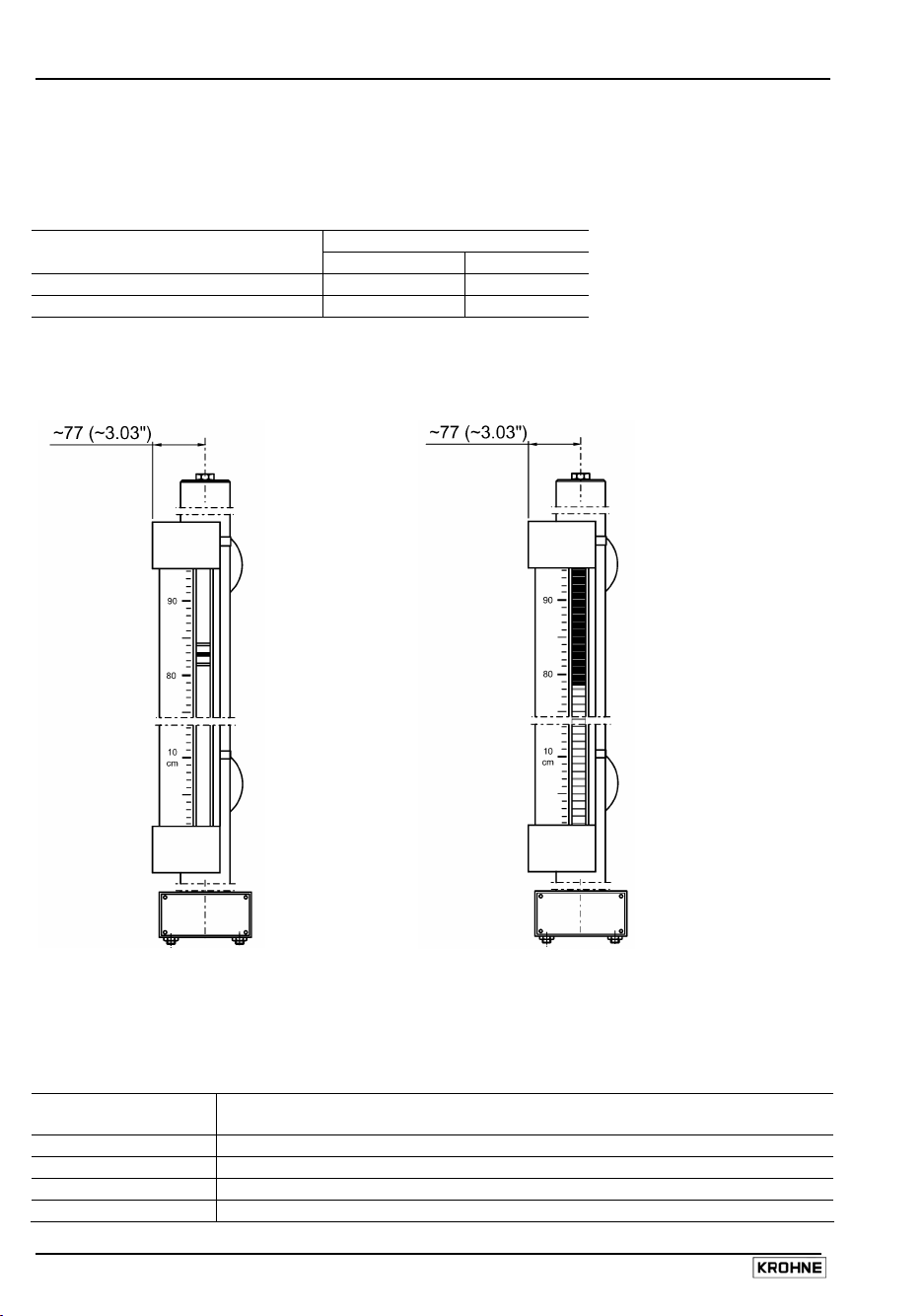
7.5.2 Indicator dimensions
BM 26 A with standard bar indicator BM 26 A with optional flap indicator
Dimensions in mm and (inches)
7.5.3 Overall dimensions of measuring tube classes (with loose or welding neck flanges)
The BM 26 A is divided into four different classes that define the positions of the process
connections.
BM 26 A measuring
tube class
BM 26 A/C Equipped with two lateral connections
BM 26 A/D Equipped with two axial connections
BM 26 A/E Equipped with one lateral entry and one bottom axial exit connection
BM 26 A/F Equipped with one lateral entry and one top axial exit connection
44 Installation and Operating Instructions BM 26 A
Description
Page 45

BM 26 A/C/RR BM 26 A/C/RR
Welding neck flange Loose (EN-DIN) flange
BM 26 A/C/B BM 26 A/C/AG BM 26 A/C/IC/TR or /HR
(heater sub-type C) (anti-freeze sub-type C) TR low, HR high temp.
Loose (EN-DIN) flange Welding neck flange Loose (EN-DIN) flange
(lagged)
The dimensions are given in mm (inches).
Installation and Operating Instructions BM 26 A 45
Page 46

BM 26 A/D/RR BM 26 A/D/RR
Welding neck flange Loose (EN-DIN) flange
BM 26 A/E/RR BM 26 A/E/RR
Welding neck flange Loose (EN-DIN) flange
The dimensions are given in mm (inches).
46 Installation and Operating Instructions BM 26 A
Page 47

BM 26 A/F/RR BM 26 A/F/RR
Welding neck flange Loose (EN-DIN) flange
The dimensions are given in mm (inches).
7.5.4 Distance of welding neck flange raised facing from measuring tube axis
Refer to the diagrams in section 7.5.3
Flange, process connection ratings BM 26 A tube axis to
DN 15 PN 40, welding neck flange 79.5 / 3.13“
DN 20 PN 40, welding neck flange 81.5 / 3.21“
DN 25 PN 40, welding neck flange 81.5 / 3.21“
DN 40 PN 40, welding neck flange 86.5 / 3.41“
DN 50 PN 40, welding neck flange 89.5 / 3.52“
½” ASME 150LB, welding neck flange 89.5 / 3.52“
1” ASME 150LB, welding neck flange 97.5 / 3.84“
1”½ ASME 150LB, welding neck flange 103.5 / 4.07“
2” ASME 150LB, welding neck flange 104.5 / 4.11“
¾” ASME 150LB, welding neck flange 93.5 / 3.68“
½” ASME 300LB, welding neck flange 93.5 / 3.68“
¾” ASME 300LB, welding neck flange 98.5 / 3.88“
1” ASME 300LB, welding neck flange 103.5 / 4.07“
1”½ ASME 300LB, welding neck flange 109.5 / 4.31“
2” ASME 300LB, welding neck flange 111.5 / 4.39“
* Dimensions in X mm / X inches
flange raised facing*
Installation and Operating Instructions BM 26 A 47
Page 48

8 Measuring principle
The instrument operates on the principle of communicating tubes. The measuring tube is connected
as adjacent to the tank (i.e. a bypass chamber) such that the same conditions are obtained in the
tube as those in the tank.
The float is equipped with a number of permanent magnets to transmit measured values to the local
indicator. Two methods of local indication are used:
Standard bar indicator
The indicator tube contains a magnetised indicator bar that follows changes in floater position.
1 Indicator tube
2 Bar (float-following indicator)
3 Measuring scale
4 Magnets set inside the float
5 Measuring tube
Optional flap indicator
The magnet mounted in the float activates (rotates) the magnetic flaps according to the liquid level in
the indicating section of the indicator. The column of reversed yellow magnetic flaps, or the vertical
position of the follower magnet, is the indication of the liquid level. Additionally, the liquid level can
be read off from a large-size scale in various units of length or graduations showing percentages or
volumes.
Remote indication is possible by choosing the level transducer and level switch options. Information
on their working principles and characteristics are given in sections 2 and 3 respectively.
1 Black front face of flap indicator
2 Flap rotates as magnet in float
moves past this point
3 Yellow reverse face of flap
indicator
4 Flap indicator tube
5 Magnets set inside the float
6 Measuring tube
7 Measuring scale
48 Installation and Operating Instructions BM 26 A
Page 49

Appendices
Appendix A: Declaration of conformity: CE
Installation and Operating Instructions BM 26 A 49
Page 50

Appendix B: Declaration of conformity: Pressure Equipment Directive 97/23/EC
50 Installation and Operating Instructions BM 26 A
Page 51

Appendix C: EC-Type Examination Certificate INERIS 02ATEX0088X
Installation and Operating Instructions BM 26 A 51
Page 52

52 Installation and Operating Instructions BM 26 A
Page 53

Installation and Operating Instructions BM 26 A 53
Page 54

54 Installation and Operating Instructions BM 26 A
Page 55

Installation and Operating Instructions BM 26 A 55
Page 56

56 Installation and Operating Instructions BM 26 A
Page 57

Installation and Operating Instructions BM 26 A 57
Page 58

58 Installation and Operating Instructions BM 26 A
Page 59

Installation and Operating Instructions BM 26 A 59
Page 60

60 Installation and Operating Instructions BM 26 A
Page 61

Installation and Operating Instructions BM 26 A 61
Page 62

62 Installation and Operating Instructions BM 26 A
Page 63

Installation and Operating Instructions BM 26 A 63
Page 64

64 Installation and Operating Instructions BM 26 A
Page 65

Installation and Operating Instructions BM 26 A 65
Page 66

66 Installation and Operating Instructions BM 26 A
Page 67

Installation and Operating Instructions BM 26 A 67
Page 68

68 Installation and Operating Instructions BM 26 A
Page 69

Installation and Operating Instructions BM 26 A 69
Page 70

Notes
70 Installation and Operating Instructions BM 26 A
Page 71

If you need to return level gauges for testing or repair to KROHNE
If installed and operated in accordance with these operating instructions, your level gauges will
rarely present any problems.
Should you nevertheless need to return a BM 26 A unit for checkout or repair, please pay strict
attention to the following points:
Due to statutory regulations concerning protection of the environment and the health and safety of
our personnel, KROHNE may only handle, test and repair returned level gauges that have been in
contact with liquids if it is possible to do so without risk to personnel and environment. This means
that KROHNE can only service your unit if it is accompanied by a certificate in line with the following
model confirming that the level gauge is safe to handle.
If the unit has been operated with toxic, caustic, flammable or water-endangering liquids, you are
kindly requested
• to check and ensure, if necessary by rinsing or neutralizing, that all cavities are free from such
dangerous substances.
(Directions on how you can find out whether the unit has to be opened and then flushed out or
neutralized are obtainable from KROHNE on request.)
• to enclose a certificate with the level gauge confirming that it is safe to handle and stating the
liquid used.
KROHNE regret that they cannot service your level gauge unless accompanied by such a certificate.
Specimen certificate
Company: Address:
Department: Name:
Tel. No.:
The enclosed liquid level gauge
Type:
KROHNE Order No. or Series No.:
has been operated with the following liquid:
Because this liquid is
water-endangering
toxic
caustic
flammable
we have
checked that all cavities in the unit are free from such substances
flushed out and neutralized all cavities in the unit
We confirm that there is no risk to man or environment through any residual liquid contained in this
level gauge.
Date: Signature:
Company stamp:
Installation and Operating Instructions BM 26 A 71
 Loading...