

Page 1

Handbook
Handbook
BM 26 BASIC/ADVANCED
BM 26 BASIC/ADVANCED
BM 26 BASIC/ADVANCEDBM 26 BASIC/ADVANCED
Stainless Steel Bypass Level Indicators for applications
up to 40 bar / 580 psi
HandbookHandbook
© KROHNE 10/2012 - 4000347004 - HB BM26 Basic/Adv R04 en
Page 2

6
: IMPRINT :::::::::::::::::::::::::::::::::::::::
BM 2
All rights reserved. It is prohibited to reproduce this documentation, or any part thereof, without
the prior written authorisation of KROHNE Messtechnik GmbH.
Subject to change without notice.
Copyright 2012 by
KROHNE Messtechnik GmbH - Ludwig-Krohne-Str. 5 - 47058 Duisburg (Germany)
2
www.krohne.com 10/2012 - 4000347004 - HB BM26 Basic/Adv R04 en
Page 3

BM 26 BASIC/ADVANCED
CONTENTS
1 Safety instructions 5
1.1 Intended use ..................................................................................................................... 5
1.2 Certification ...................................................................................................................... 5
1.3 Safety instructions from the manufacturer ..................................................................... 6
1.3.1 Disclaimer ............................................................................................................................... 6
1.3.2 Product liability and warranty ................................................................................................ 7
1.3.3 Information concerning the documentation........................................................................... 7
1.3.4 Warnings and symbols used................................................................................................... 8
1.4 Safety instructions for the operator................................................................................. 8
2 Device description 9
2.1 Scope of delivery............................................................................................................... 9
2.2 Device description .......................................................................................................... 10
2.3 Nameplates .................................................................................................................... 11
2.3.1 Visual Check.......................................................................................................................... 11
2.3.2 Nameplates........................................................................................................................... 11
2.3.3 Other device data .................................................................................................................. 14
3 Installation 15
3.1 Storage ........................................................................................................................... 15
3.2 Transportation ................................................................................................................ 16
3.3 Remove all packing before installation ......................................................................... 16
3.4 General requirements .................................................................................................... 18
3.4.1 Pressure and temperature ranges....................................................................................... 18
3.4.2 How to attach the bypass level indicator to the tank ........................................................... 19
3.5 Level indicator column................................................................................................... 21
3.6 Optional analog transmitter ........................................................................................... 22
3.7 Optional limit switch....................................................................................................... 23
3.8 Electromagnetic compatibility ....................................................................................... 26
4 Electrical connections 27
4.1 Optional analog transmitter ........................................................................................... 27
4.2 Optional limit switches ................................................................................................... 29
4.3 Protection category ........................................................................................................30
5 Start-up 31
5.1 Start-up checklist........................................................................................................... 31
5.2 Operating concept ..........................................................................................................31
www.krohne.com10/2012 - 4000347004 - HB BM26 Basic/Adv R04 en
3
Page 4

CONTENTS
BM 26 BASIC/ADVANCED
6 Operation 32
6.1 Local display options ......................................................................................................32
6.1.1 Level indicator column ......................................................................................................... 32
6.1.2 Analog transmitter (option) .................................................................................................. 33
6.2 Errors.............................................................................................................................. 37
6.2.1 Error indication ..................................................................................................................... 37
6.2.2 Error handling....................................................................................................................... 38
7 Service 41
7.1 Periodic maintenance..................................................................................................... 41
7.2 Keep the device clean..................................................................................................... 41
7.3 How to replace device components ............................................................................... 41
7.3.1 Service warranty ................................................................................................................... 41
7.4 Availability of services .................................................................................................... 42
7.4.1 General notes........................................................................................................................ 42
7.4.2 List of spare parts................................................................................................................. 42
7.4.3 List of accessories ................................................................................................................ 43
7.5 Availability of services .................................................................................................... 43
7.6 Returning the device to the manufacturer..................................................................... 44
7.6.1 General information.............................................................................................................. 44
7.6.2 Form (for copying) to accompany a returned device............................................................ 45
7.7 Disposal .......................................................................................................................... 45
8 Technical data 46
8.1 Measuring principle........................................................................................................46
8.2 Technical data: general information .............................................................................. 47
8.3 Technical data: optional analog transmitter.................................................................. 51
8.4 Technical data: optional limit switches.......................................................................... 56
8.5 Basic version: Dimensions and weights ........................................................................ 58
8.6 Advanced version: Dimensions and weights.................................................................. 66
8.7 Analog transmitter: Dimensions and weight ................................................................. 74
8.8 Support bracket option: Dimensions and weight........................................................... 75
8.9 Guidelines for maximum operating pressure................................................................ 76
8.10 Floats ............................................................................................................................ 78
9 Appendix 79
9.1 Liquid level offset: description....................................................................................... 79
9.2 Liquid level offset: correction data ................................................................................ 80
9.3 Glossary .......................................................................................................................... 83
9.4 Order code ...................................................................................................................... 84
9.5 Spare parts code ............................................................................................................ 92
10 Notes 94
4
www.krohne.com 10/2012 - 4000347004 - HB BM26 Basic/Adv R04 en
Page 5
BM 26 BASIC/ADVANCED
1.1 Intended use
This magnetic level indicator measures the level or volume of liquids.
It is installed next to open or pressurized tanks. With the applicable options, it is resistant to
difficult service conditions and liquids that are poisonous, flammable, or that cause corrosion.
CAUTION!
Responsibility for the use of the measuring devices with regard to suitability, intended use and
corrosion resistance of the used materials against the measured fluid lies solely with the
operator.
INFORMATION!
The manufacturer is not liable for any damage resulting from improper use or use for other than
the intended purpose.
1.2 Certification
SAFETY INSTRUCTIONS 1
In accordance with KROHNE’s commitment to customer service and safety, the level indicators
described in this handbook meet the following safety requirements:
• EMC Directive 2004/108/EC in conjunction with EN 61326-1: 2006
• Low Voltage Directive 2006/95/EC in conjunction with EN 61010-1: 2001
• Pressure Equipment Directive 97/23/EC in conjunction with CODAP® 2010
INFORMATION!
The optimized design of the Basic version is not subject to PED test requirements (CE marking is
not applicable). The Advanced version agrees with the requirements for CE marking.
The Low Voltage Directive is only applicable to limit switches (non-NAMUR option).
www.krohne.com10/2012 - 4000347004 - HB BM26 Basic/Adv R04 en
5
Page 6

1 SAFETY INSTRUCTIONS
1.3 Safety instructions from the manufacturer
1.3.1 Disclaimer
The manufacturer will not be liable for any damage of any kind by using its product, including,
but not limited to direct, indirect or incidental and consequential damages.
This disclaimer does not apply in case the manufacturer has acted on purpose or with gross
negligence. In the event any applicable law does not allow such limitations on implied warranties
or the exclusion of limitation of certain damages, you may, if such law applies to you, not be
subject to some or all of the above disclaimer, exclusions or limitations.
Any product purchased from the manufacturer is warranted in accordance with the relevant
product documentation and our Terms and Conditions of Sale.
The manufacturer reserves the right to alter the content of its documents, including this
disclaimer in any way, at any time, for any reason, without prior notification, and will not be liable
in any way for possible consequences of such changes.
BM 26 BASIC/ADVANCED
6
www.krohne.com 10/2012 - 4000347004 - HB BM26 Basic/Adv R04 en
Page 7

BM 26 BASIC/ADVANCED
1.3.2 Product liability and warranty
Bypass level indicators from KROHNE are designed solely for measuring the level and
volume of liquids.
Responsibility as to suitability and intended use of these level indicators rests solely with the
operator. The supplier does not accept any liability resulting from misuse by the operator.
Improper installation and operation of the level transmitters may lead to loss of warranty. In
addition, the “General conditions of sale“ which forms the basis of the purchase agreement are
applicable.
1.3.3 Information concerning the documentation
To prevent any injury to the user or damage to the device it is essential that you read the
information in this document and observe applicable national standards, safety requirements
and accident prevention regulations.
If this document is not in your native language and if you have any problems understanding the
text, we advise you to contact your local office for assistance. The manufacturer can not accept
responsibility for any damage or injury caused by misunderstanding of the information in this
document.
SAFETY INSTRUCTIONS 1
This document is provided to help you establish operating conditions, which will permit safe and
efficient use of this device. Special considerations and precautions are also described in the
document, which appear in the form of underneath icons.
www.krohne.com10/2012 - 4000347004 - HB BM26 Basic/Adv R04 en
7
Page 8
1 SAFETY INSTRUCTIONS
1.3.4 Warnings and symbols used
Safety warnings are indicated by the following symbols.
DANGER!
This information refers to the immediate danger when working with electricity.
DANGER!
This warning refers to the immediate danger of burns caused by heat or hot surfaces.
DANGER!
This warning refers to the immediate danger when using this device in a hazardous atmosphere.
DANGER!
These warnings must be observed without fail. Even partial disregard of this warning can lead to
serious health problems and even death. There is also the risk of seriously damaging the device
or parts of the operator's plant.
BM 26 BASIC/ADVANCED
WARNING!
Disregarding this safety warning, even if only in part, poses the risk of serious health problems.
There is also the risk of damaging the device or parts of the operator's plant.
CAUTION!
Disregarding these instructions can result in damage to the device or to parts of the operator's
plant.
INFORMATION!
These instructions contain important information for the handling of the device.
LEGAL NOTICE!
This note contains information on statutory directives and standards.
• HANDLING
HANDLING
HANDLINGHANDLING
This symbol designates all instructions for actions to be carried out by the operator in the
specified sequence.
i RESULT
RESULT
RESULTRESULT
This symbol refers to all important consequences of the previous actions.
1.4 Safety instructions for the operator
WARNING!
In general, devices from the manufacturer may only be installed, commissioned, operated and
maintained by properly trained and authorized personnel.
This document is provided to help you establish operating conditions, which will permit safe and
efficient use of this device.
8
www.krohne.com 10/2012 - 4000347004 - HB BM26 Basic/Adv R04 en
Page 9

BM 26 BASIC/ADVANCED
2.1 Scope of delivery
INFORMATION!
Check the packing list to see if you have received all that you require.
The device will be delivered in one box.
INFORMATION!
Inspect the cartons carefully for damages or signs of rough handling. Report damage to the
carrier and to the local office of the manufacturer.
DEVICE DESCRIPTION 2
Figure 2-1: Scope of delivery
1 Measuring chamber with the indicator column and optional indicator scale
2 Optional analog transmitter
3 Optional limit switches (not attached to the device)
4 Magnet (to set the indicator column to zero after installation)
5 Quick Start and Handbook
INFORMATION!
No special tools, no training required!
www.krohne.com10/2012 - 4000347004 - HB BM26 Basic/Adv R04 en
9
Page 10

2 DEVICE DESCRIPTION
2.2 Device description
Magnetic level indicators have a measuring chamber that contains a magnetic float. It is
attached vertically to the side of open or pressurized tanks. A level indicator is attached adjacent
to the measuring chamber. As the float moves up and down, it rotates a column of flaps inside
the glass tube of the indicator. If an analog level transmitter is also attached adjacent to the
measuring chamber, it is possible to have an output current that can be monitored from a
remote station. Optional bistable switches let the user monitor important measurement limits.
BM 26 BASIC/ADVANCED
The measuring chamber of the Basic
232 psig (depending on the length of the chamber). It is unnecessary to test the measuring
chamber according to PED 97/23/EC as it does not have to comply with CE marking
requirements. It is also ideal for measuring liquids with a density ≥0.8 kg/l / ≥49.9 lb/ft³ and
temperatures up to 150°C/ 300°F.
The Advanced
Advanced version is ideal for measuring liquids with density range of 0.58...2.0 kg/l /
AdvancedAdvanced
36.2...124.8 lb/ft³, temperatures up to 300°C/ 570°F or pressures up to 40 barg / 580 psig.
Basic version has a maximum operating pressure of 16 barg /
BasicBasic
WARNING!
Pressure Equipment Directive 97/23/EC data
•
This device is designed to function at near constant pressure conditions. It is not designed for
operating conditions where vibration or fatigue stress is present.
•
Events that are not taken into account in the calculations include exceptional risks such as:
earthquakes, bad weather, fire etc.
•
The standard design calculation does not take into account the theoretical coefficient of
corrosion. The product circulating in the device must not have properties that give rise to
surface erosion.
•
Our conformity declaration is limited to the parts of the device that are pressurized. It does
not include parts that can be dismantled (valves, ...).
You can also order these accessories:
• Limit switches
10
www.krohne.com 10/2012 - 4000347004 - HB BM26 Basic/Adv R04 en
Page 11
BM 26 BASIC/ADVANCED
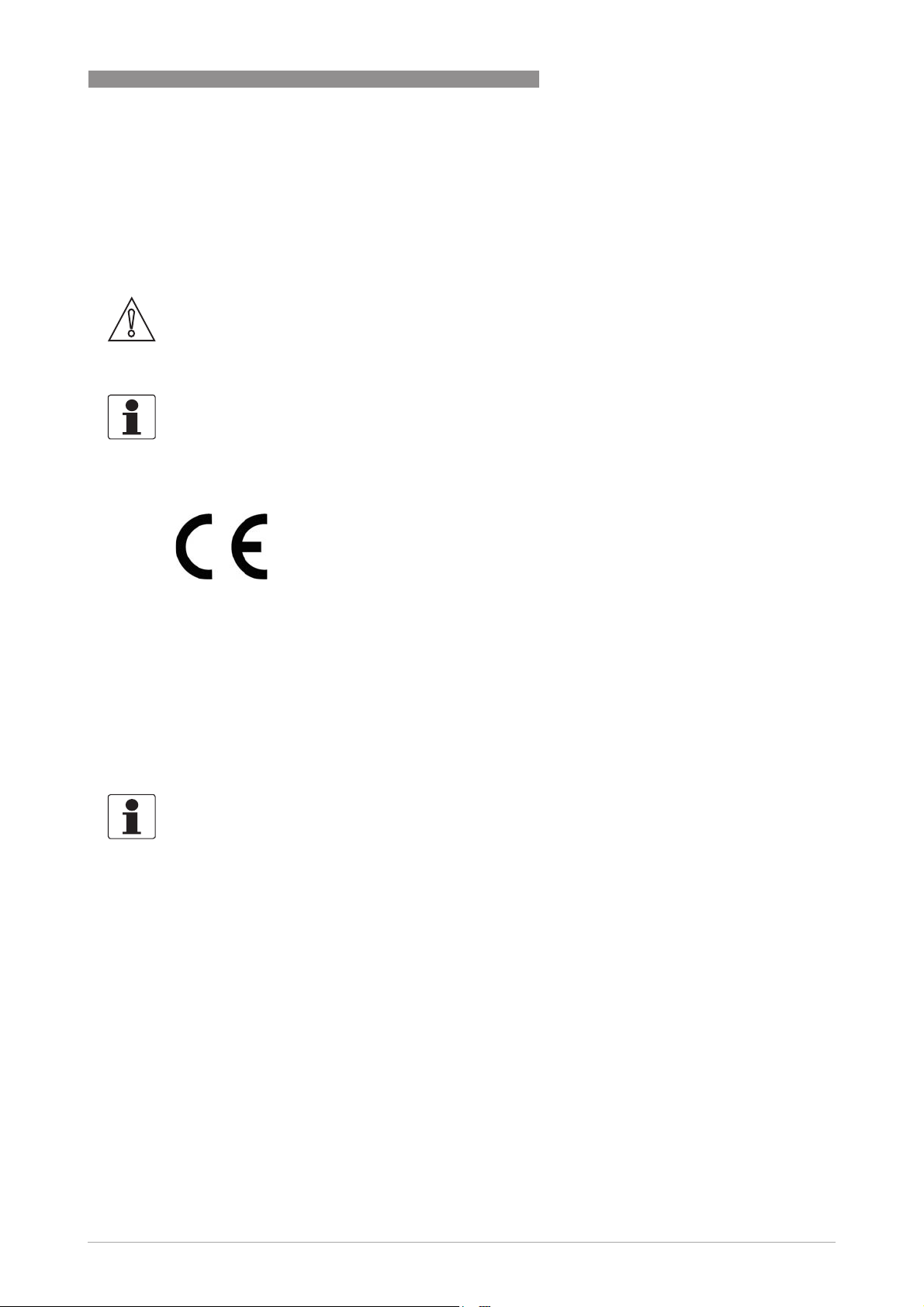
2.3 Nameplates
INFORMATION!
Look at the device nameplate to ensure that the device is delivered according to your order.
Check for the correct supply voltage printed on the nameplate.
2.3.1 Visual Check
DEVICE DESCRIPTION 2
Figure 2-2: Visual check
• Check the delivery for damage.
• Are all the wetted components (chamber, flanges and gaskets) resistant to the product in the
tank?
• Compare the data on the nameplate with your order data.
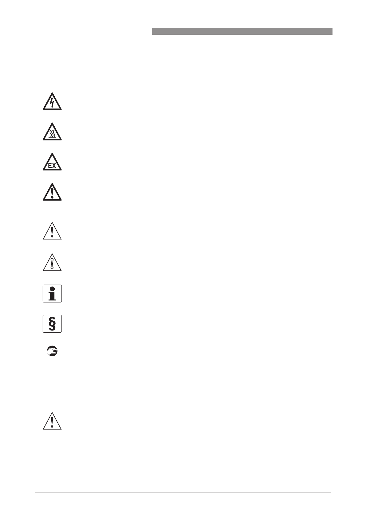
2.3.2 Nameplates
Figure 2-3: Location of device nameplates
1 Measuring chamber nameplate
2 Analog transmitter nameplate
3 Limit switch nameplate (housing cover)
4 Limit switch nameplate (housing)
www.krohne.com10/2012 - 4000347004 - HB BM26 Basic/Adv R04 en
11
Page 12

2 DEVICE DESCRIPTION
Figure 2-4: Basic version: Non-Ex nameplate
BM 26 BASIC/ADVANCED
L
Figure 2-5: Advanced version: Non-Ex nameplate
1 Customer tag number
2 Measuring tube volume in litres
3 Maximum allowable pressure (P
4 Factory serial number
5 Purchase order number
6 Model name and number
7 Designation code (VF code given in the order)
8 Year of manufacture
9 Maximum allowable temperature (T
10 Test pressure (P
ment Directive 97/23/EC.
at 20°C) - if the device agrees with the requirements of Categories I, II or III of the Pressure Equip-
t
)
s
)
s
L
12
www.krohne.com 10/2012 - 4000347004 - HB BM26 Basic/Adv R04 en
Page 13
BM 26 BASIC/ADVANCED
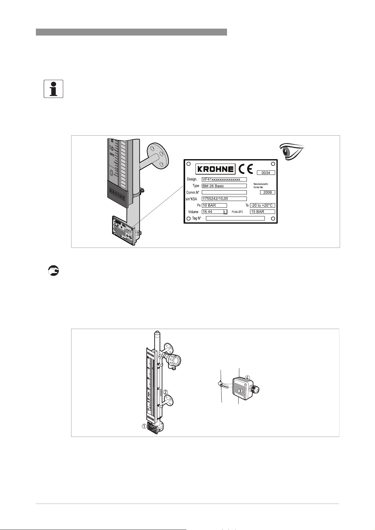
Figure 2-6: Limit switch: Non-Ex nameplate (housing cover)
1 Non-NAMUR option
2 NAMUR option
3 Model
4 Designation code (VF code given in the order)
5 Date of manufacture
6 Factory serial number and bar code
7 Electrical data
DEVICE DESCRIPTION 2
Figure 2-7: Limit switch: Non-Ex nameplate (housing)
1 Non-NAMUR option
2 NAMUR option
3 Electrical schema
4 Factory serial number
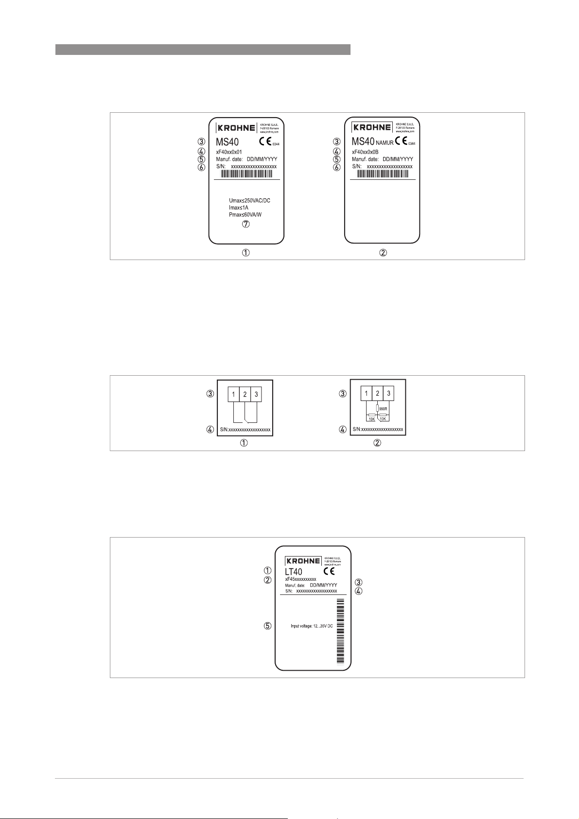
Figure 2-8: Analog transmitter: Non-Ex nameplate
1 Model
2 Designation code (VF code given in the order)
3 Date of manufacture
4 Factory serial number
5 Input voltage
www.krohne.com10/2012 - 4000347004 - HB BM26 Basic/Adv R04 en
13
Page 14
2 DEVICE DESCRIPTION
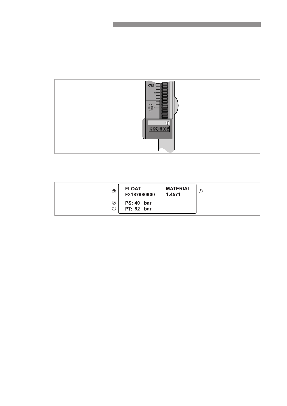
2.3.3 Other device data
The supplier's bottom logo plate has a sticker:
Figure 2-9: Other device data
1 Float data sticker
BM 26 BASIC/ADVANCED
Figure 2-10: Float data sticker
1 Test pressure, PT, in bar
2 Maximum allowable pressure, PS, in bar
3 Float drawing number
4 Float material
14
www.krohne.com 10/2012 - 4000347004 - HB BM26 Basic/Adv R04 en
Page 15
BM 26 BASIC/ADVANCED
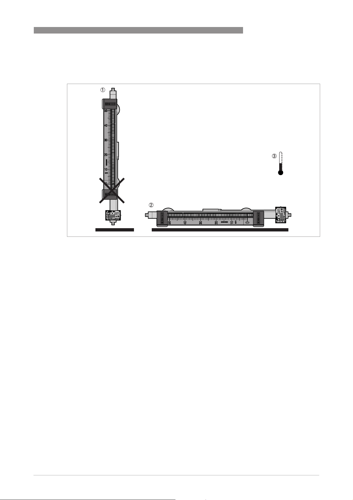
3.1 Storage
INSTALLATION 3
Figure 3-1: Storage conditions
1 Do not keep the device in a vertical position before installation.
2 Put the device on its side.
3 Storage temperature range: -50…+80°C/ -58…+176°F
• Store the device in a dry and dust-free location.
• Store the device in its original packing.
www.krohne.com10/2012 - 4000347004 - HB BM26 Basic/Adv R04 en
15
Page 16
3 INSTALLATION
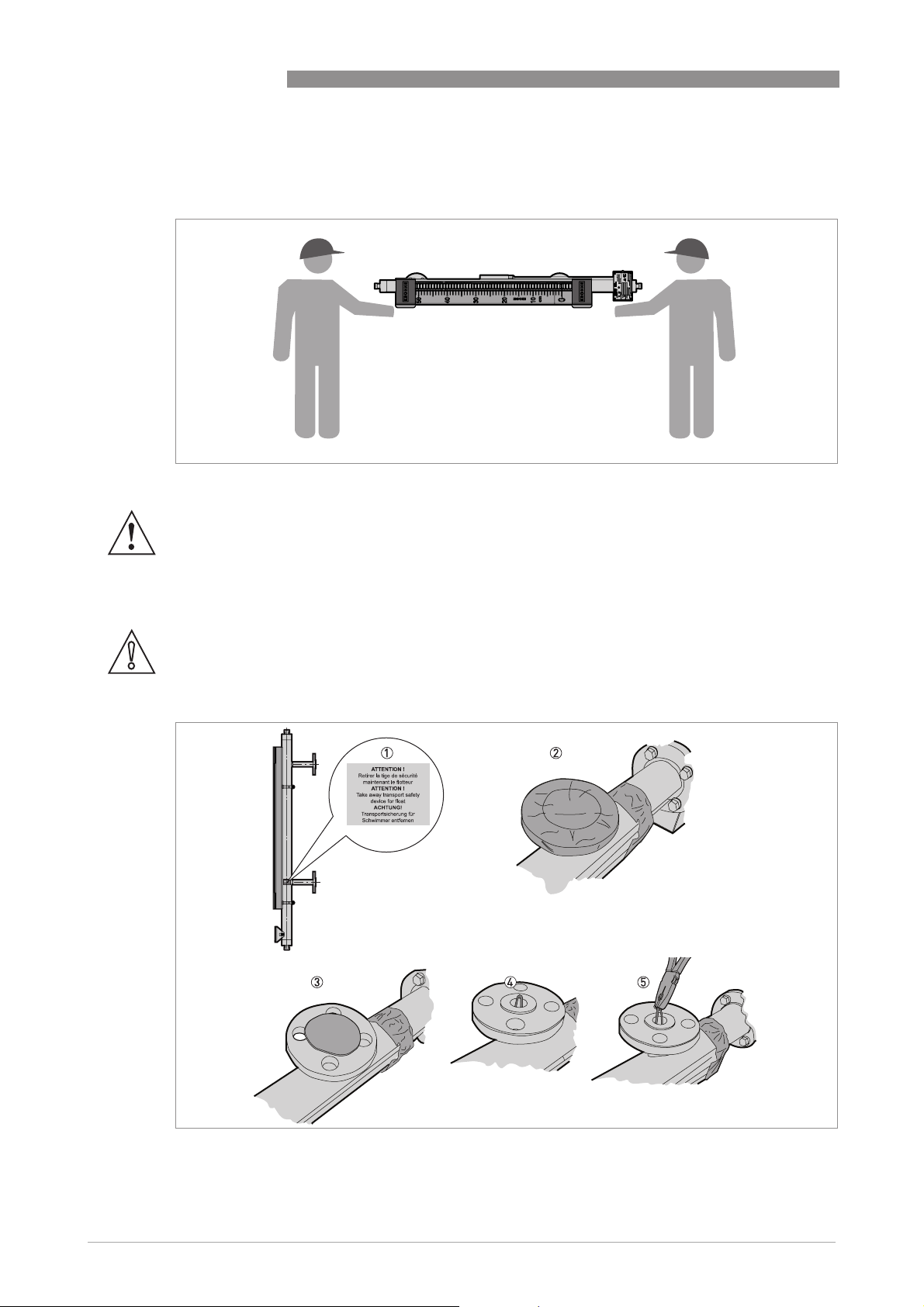
3.2 Transportation
Figure 3-2: Transportation
WARNING!
The indicator column is made of Pyrex
If you do not lift the device carefully, you can cause damage to the device.
®
glass.
BM 26 BASIC/ADVANCED
3.3 Remove all packing before installation
CAUTION!
Make sure that the measuring chamber does not contain unwanted objects (dirt etc.)
How to remove the float lock pin (devices with side process connections)
16
Figure 3-3: How to remove the float lock pin (devices with side process connections)
www.krohne.com 10/2012 - 4000347004 - HB BM26 Basic/Adv R04 en
Page 17
BM 26 BASIC/ADVANCED
How to remove the float lock pin (devices with side process connections)
1 Check the measuring chamber for a red sticker next to the bottom side process connection.
i Sticker text: ATTENTION! Take away transport safety device for float.
2 Remove the adhesive tape around the top and bottom process connections.
3 Remove the plastic protection from the top and bottom process connections.
4 Find the lock pin.
5 Remove the lock pin with a pair of pliers.
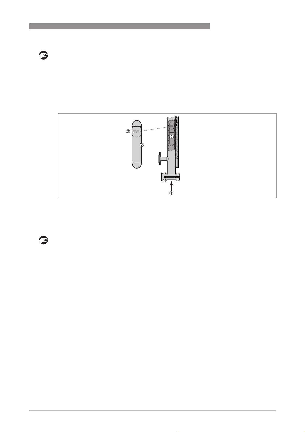
How to put the float in the measuring chamber
INSTALLATION 3
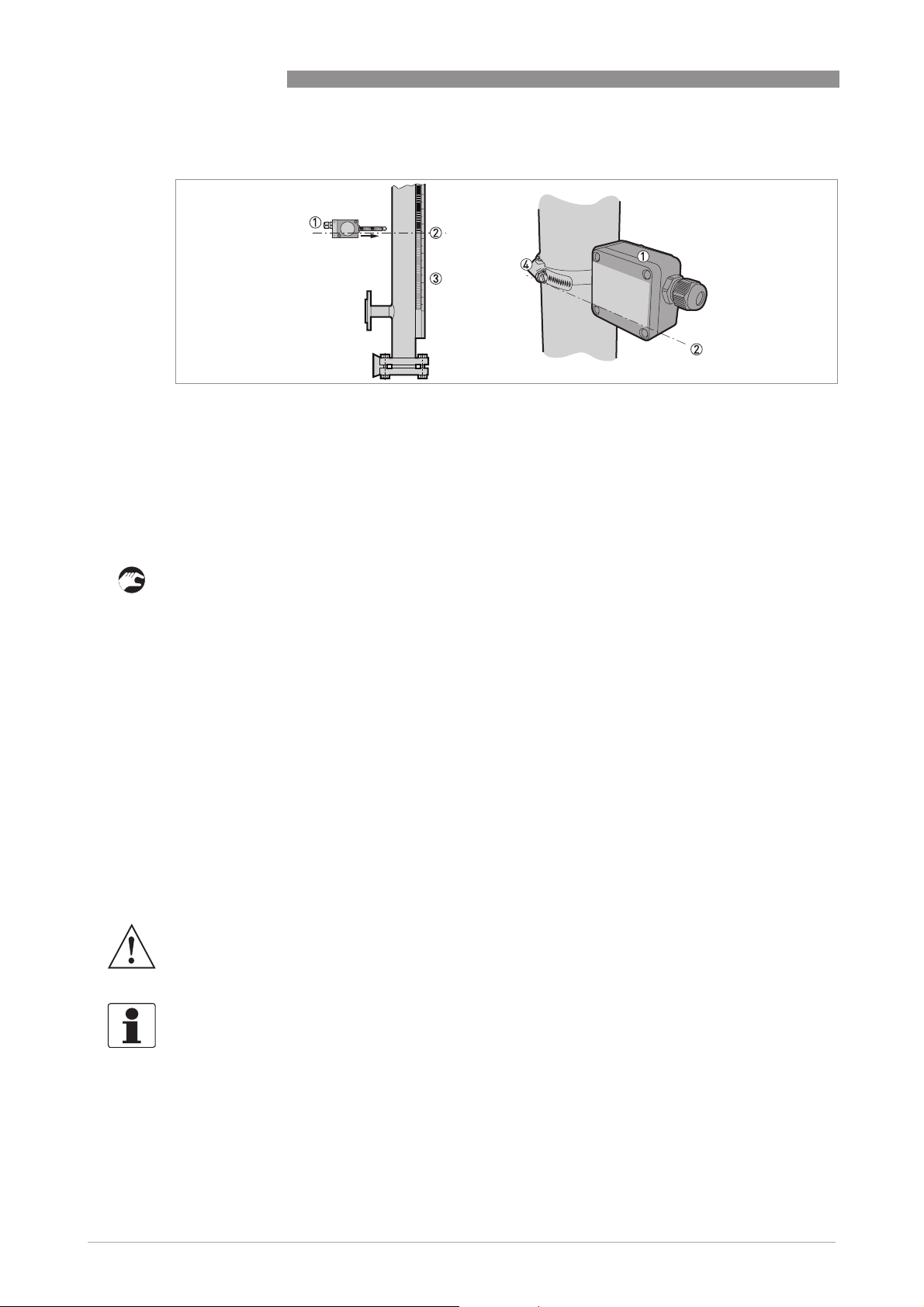
Figure 3-4: How to put the float in the measuring chamber (if it is delivered separately)
1 Put the float in here
2 Float
3 The float data (date of manufacture, P
the measuring chamber
, float material etc.) must be at the top of the float when you put the float in
s/Pt
How to put the float in the measuring chamber (if it is delivered separately)
• Remove the bottom blind flange or plug (if the basic version has the 1¼¨ drain option).
• Put the top of the float (the float data is on the top part of the float) in the measuring chamber
first.
• Align the gaskets.
• Tighten the nuts on the blind flange to the correct torque (11 Nm in operating conditions,
23.5 Nm in test conditions). The 1¼¨ plug must be tightened in agreement with good
engineering practice.
www.krohne.com10/2012 - 4000347004 - HB BM26 Basic/Adv R04 en
17
Page 18
3 INSTALLATION
3.4 General requirements
3.4.1 Pressure and temperature ranges
BM 26 BASIC/ADVANCED
1 Process temperature
Basic version: -40…+150°C/ -40…300°F
Advanced version: -40...+300°C/ -40…570°F
Ex devices: refer to supplementary instructions
2 Maximum process pressure
Basic version: 16 barg / 232 psig (depends on the length of the measuring chamber. For more data, refer to
for maximum operating pressure
Advanced version: 40 barg / 580 psig (according to the flange pressure rating. For more data, refer to
maximum operating pressure
3 Ambient temperature
Non-Ex devices: -40…+80°C/ -40…+176°F
Ex devices: refer to supplementary instructions
on page 76).
on page 76).
Guidelines
Guidelines for
WARNING!
Refer to the operating conditions data on the device nameplate. The data is applicable to that
device.
WARNING!
PED 97/23/EC requirement:
PED 97/23/EC requirement: External pressure must be equal to atmospheric pressure.
PED 97/23/EC requirement:PED 97/23/EC requirement:
18
www.krohne.com 10/2012 - 4000347004 - HB BM26 Basic/Adv R04 en
Page 19
BM 26 BASIC/ADVANCED
3.4.2 How to attach the bypass level indicator to the tank
INSTALLATION 3
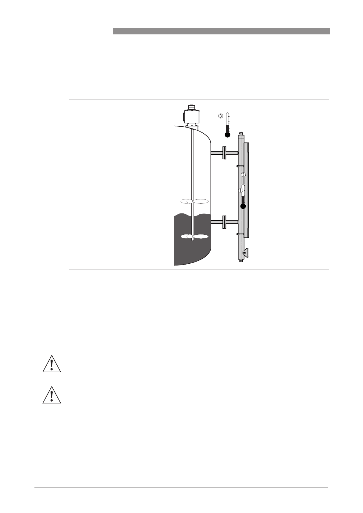
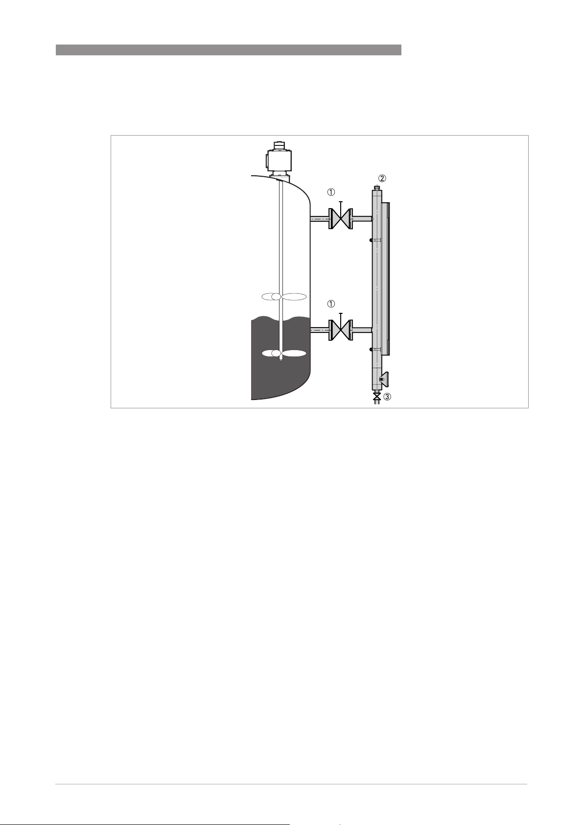
Figure 3-5: How to attach the bypass level indicator to the tank
1 Optional isolation valve
2 Optional vent
3 Optional drain with isolation valve
Obey the instructions that follow:
• Select bolts and gaskets (not supplied) that agree with the pressure rating of the process
connection and the operating pressure.
• Install the bypass level indicator vertically on the tank.
• Make sure that there is no contamination (dirt etc.) or unwanted objects in the measuring
chamber.
• Make sure that mechanical loadings do not cause damage to the process connections. If
necessary, put supports on the device.
• Install shut-off valves so that the device can be cleaned separately from the tank. Drain the
device only when it is isolated from the tank.
www.krohne.com10/2012 - 4000347004 - HB BM26 Basic/Adv R04 en
19
Page 20

3 INSTALLATION
Figure 3-6: Stay away from the process connections
WARNING!
Stay away from the process connections. If you stand on the process connections, you can cause
damage to the device and the installation.
BM 26 BASIC/ADVANCED
DANGER!
°
Make sure that the outer surface temperature of the device is not more than 60
°
surface temperature is more than 60
C / 140°F, use the device with precautions that agree with
C / 140°F. If the
Health and Safety rules and regulations.
WARNING!
Pressure Equipment Directive 97/23/EC data
•
The process connections must be attached correctly to prevent mechanical stress. The axis
of the process connection must be parallel to and centred with the axis of the tank's process
connections. Tighten the process connections in agreement with the design code.
•
The user must take necessary steps to protect the installed device from shock waves (water
hammer). A pressure limiting valve must protect the installation.
•
The effective pressure of the installation (the maximum permitted by the pressure limiting
valve) must never be greater than the maximum permitted pressure, P
device nameplate.
•
Make sure that the parts in contact with the fluid are compatible with the fluid and conform to
the ageing characteristics of the measurement environment and the fluid used. These have
either been recommended in the instructions or form the subject of a particular specification
in the contract.
•
The external pressure, P
•
If stainless steel devices are more than 6 m / 20 ft high, we recommend more anchoring
, must be equal to atmospheric pressure, P
ext
points.
, marked on the
s
(P
atmos
ext
= P
atmos
).
20
CAUTION!
Before you fill the tank, make sure that the column of rotating flaps is set to zero (the flaps are
all black). If not, the device may incorrectly indicate the level.
www.krohne.com 10/2012 - 4000347004 - HB BM26 Basic/Adv R04 en
Page 21
BM 26 BASIC/ADVANCED
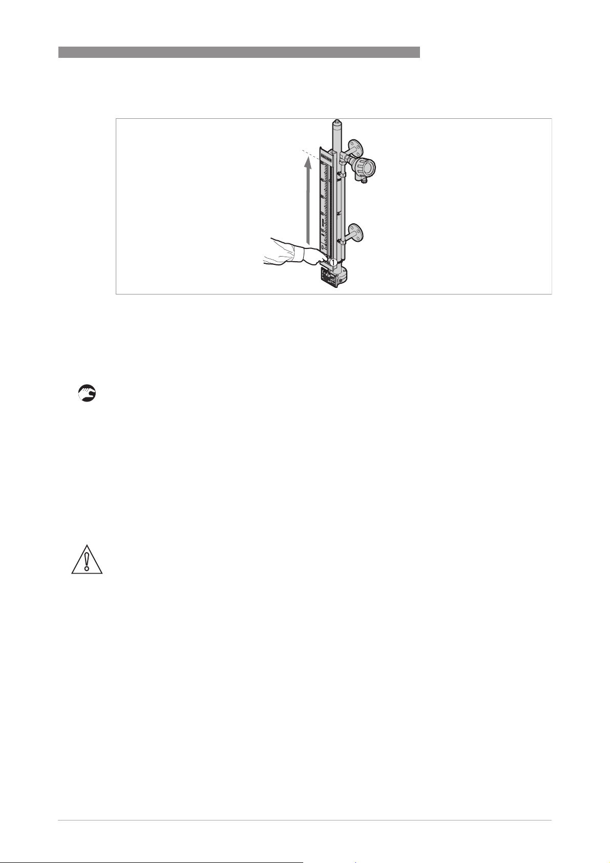
Figure 3-7: Set the indicator column to zero
1 Magnet - point the red end of the magnet at the glass tube
Equipment needed:
• Magnet (supplied with the device)
INSTALLATION 3
How to make sure the column of rotating flaps is set to zero
• Hold the magnet in front of the glass tube at the bottom of the indicator column.
i Make sure the red end of the magnet points at the glass tube.
• Move the magnet slowly up to the top the glass tube.
i The flaps all turn to black. The indicator column is set to zero. You can now fill the tank.
3.5 Level indicator column
The level indicator column is attached to the measuring chamber before delivery. Customer
order data is used to calibrate its position. No other adjustment is necessary.
CAUTION!
Customer order data is used to calibrate the device. If liquid density changes, the device will not
measure correctly. Please contact our nearest sales office for advice.
www.krohne.com10/2012 - 4000347004 - HB BM26 Basic/Adv R04 en
21
Page 22
3 INSTALLATION
3.6 Optional analog transmitter
The analog transmitter is attached to the measuring chamber before delivery. Customer order
data is used to calibrate its position. No other adjustment is necessary.
WARNING!
Too much heat can cause damage to the analog transmitter. If the process temperature is more
°
than 120
the process temperature is more than 150
transmitter.
C / 250°F, put insulation between the bypass chamber and the analog transmitter. If
BM 26 BASIC/ADVANCED
°
C / 300°F, do not cover any part of the analog
Figure 3-8: Analog transmitter and insulation for the bypass chamber
1 Analog transmitter
2 Bypass chamber (cross-section)
3 If temperature is more 120°C/ 250°F, put insulation between the bypass chamber and the analog transmitter
4 Insulation (cross-section). If temperature is more 150°C/ 300°F, do not cover any part of the analog transmitter with
insulation.
CAUTION!
Do not move the analog transmitter. If you adjust the position of this device, the current output
will be incorrect.
CAUTION!
Customer order data is used to calibrate the device. If liquid density changes, the device will not
measure correctly. Please contact our nearest sales office for advice.
22
www.krohne.com 10/2012 - 4000347004 - HB BM26 Basic/Adv R04 en
Page 23
BM 26 BASIC/ADVANCED
3.7 Optional limit switch
INFORMATION!
The level switches are not attached to the device before delivery. Remove the switches from the
packing and obey the instructions that follow.
WARNING!
Too much heat can cause damage to the limit switch. If you put insulation around the bypass
level indicator, do not cover the limit switch housing. Make sure that there is approximately
¨
15 mm / 0.6
of empty space between the limit switch and the insulation.
INSTALLATION 3
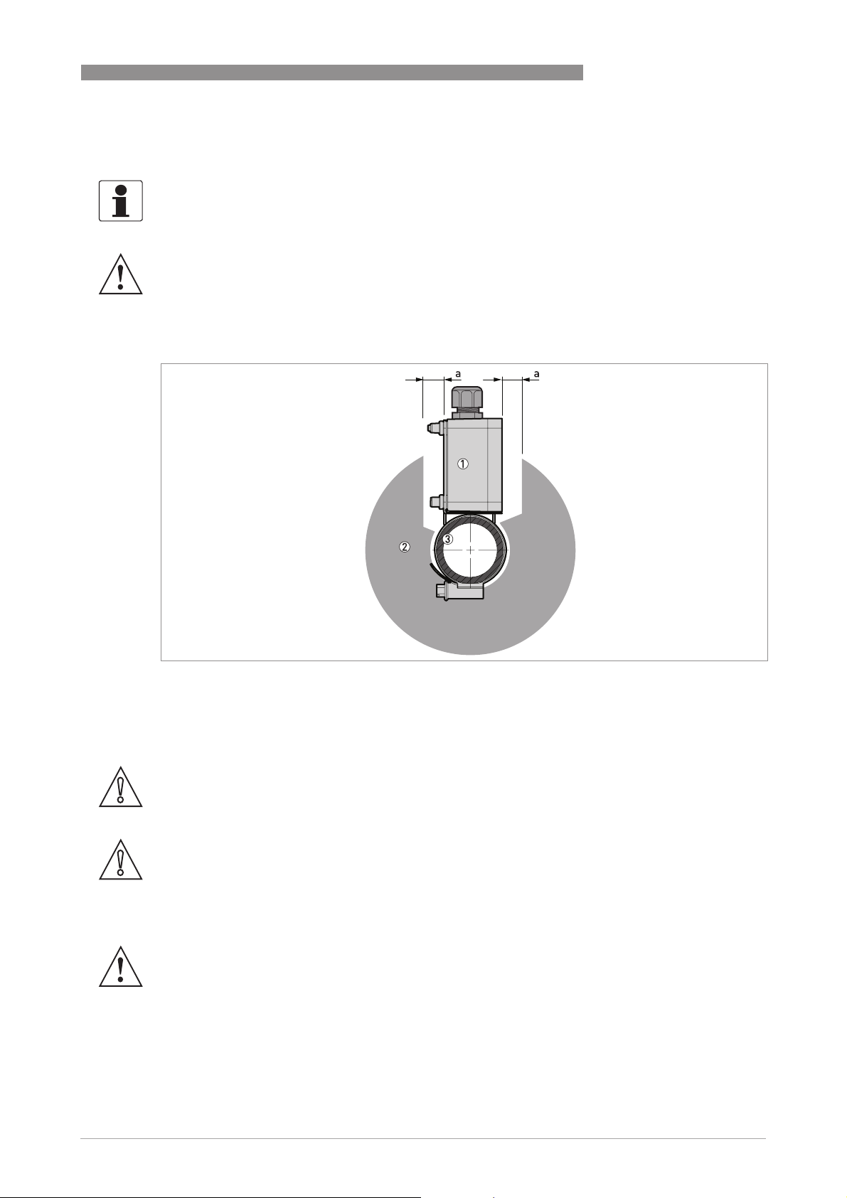
Figure 3-9: Limit switches and insulation for the measuring chamber
1 Limit switch housing
2 Insulation around the measuring chamber (cross-section)
3 Measuring chamber (cross-section)
Empty space between the limit switch and the insulation for the measuring chamber, a ≥15 mm / 0.6¨.
CAUTION!
If liquid density changes, the switch will not detect level correctly. Recalculate the position of the
switch according to the true liquid density and repeat the installation procedure that follows.
CAUTION!
The switching point of the switch when the level increases is not in the same as the switching
point of the switch when the level decreases. Does the limit switch have to be open when the
float is above (for HIGH limit switches) or below (for LOW limit switches) the switching point? For
more data, refer to Definition of switching point offset
Definition of switching point offset.
Definition of switching point offsetDefinition of switching point offset
WARNING!
If you put insulation around the bypass level indicator, do not cover the limit switch housing. Too
much heat can cause damage to the limit switch.
www.krohne.com10/2012 - 4000347004 - HB BM26 Basic/Adv R04 en
23
Page 24
3 INSTALLATION
Figure 3-10: How to attach a limit switch
1 Limit switch
2 Switching point centreline
3 Level indicator and optional measuring scale
4 Limit switch clamp
Equipment needed:
• Large slotted tip screwdriver (not supplied)
BM 26 BASIC/ADVANCED
Installation procedure
• Use the clamp to attach the limit switch to the measuring chamber. Do not tighten the clamp.
i The cable gland must be at the bottom of the housing.
• Move the limit switch until the switching point centreline is at the level required. Refer to the
level indicator scale to help you position the limit switch.
i If the indicator column does not have the scale option, it will be necessary to calculate the
vertical offset of the float magnet in relation to the level of the liquid (depends on the liquid
density). Adjust the switch position for the float magnet offset. For the vertical offset tables,
refer to the appendix in the Handbook.
• Adjust the switch position for the switching point offset.
i If the limit switch is set to LOW limit
LOW limit (the switch is open
LOW limitLOW limit
open when the float is below the
openopen
switching point), move the switch up a small distance to adjust for the offset. If the limit
switch is set to HIGH limit
HIGH limit (the switch is open
HIGH limitHIGH limit
open when the float is above the switching point),
openopen
move the switch down a small distance to adjust for the offset. For more data, refer to
Definition of switching point offset
Definition of switching point offset and Switching point offset values
Definition of switching point offsetDefinition of switching point offset
Switching point offset values.
Switching point offset valuesSwitching point offset values
• Tighten the limit switch clamp.
WARNING!
Make sure the cable gland is on the bottom the housing and is tight to stop liquid entering the
housing.
INFORMATION!
Liquid level offset
Liquid level offset
Liquid level offsetLiquid level offset
For a description of the liquid level offset, refer to Liquid level offset: description on page 79
the graphs and other correction data, refer to
Liquid level offset: correction data on page 80
. For
.
24
www.krohne.com 10/2012 - 4000347004 - HB BM26 Basic/Adv R04 en
Page 25
BM 26 BASIC/ADVANCED
Definition of switching point offset
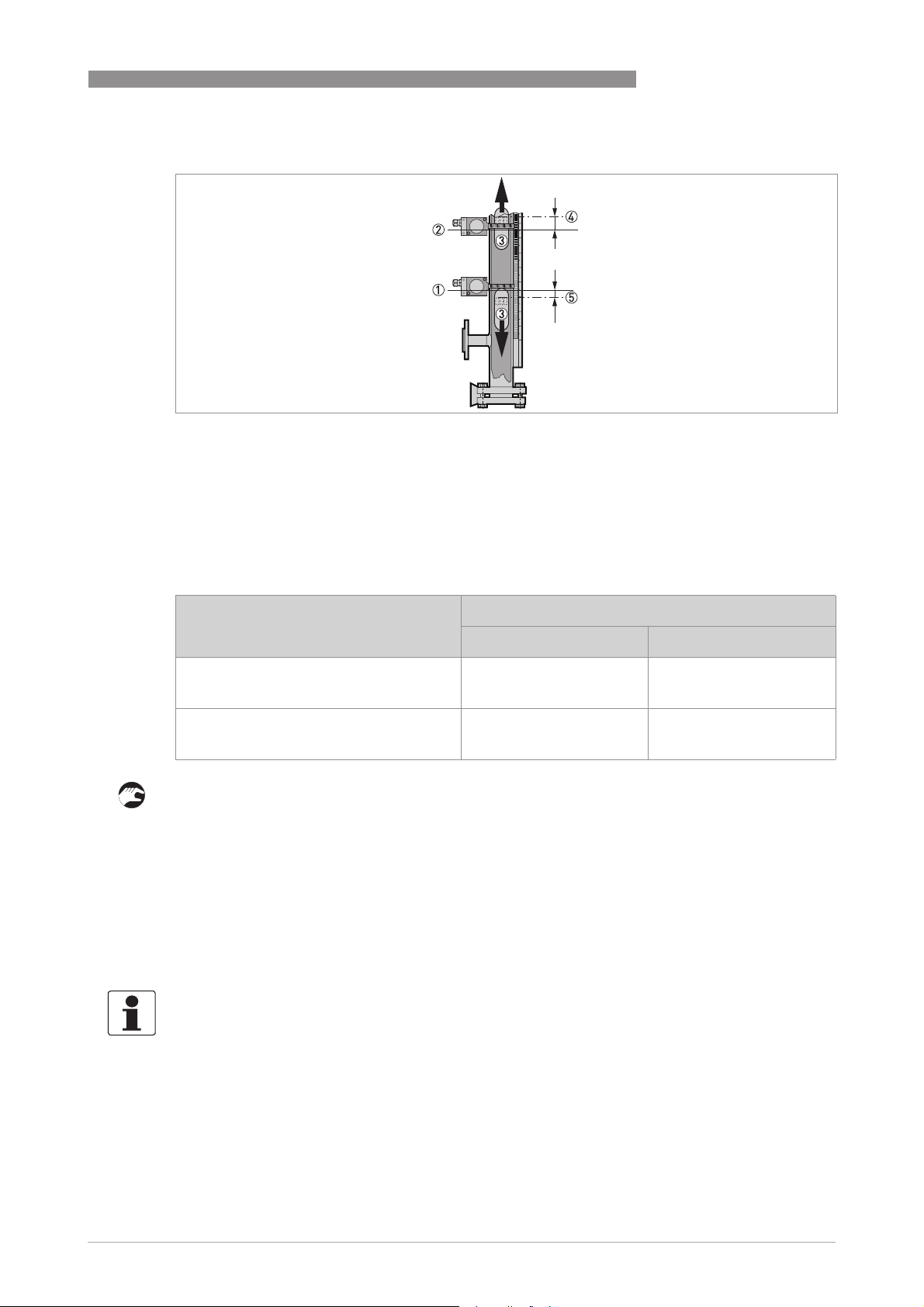
Figure 3-11: Switching point offset
1 Zero point of the limit switch
2 Zero point of the limit switch
3 Float and float magnet (switching point is in relation to the top of the magnet)
4 True switching point above a limit switch (the switch is open when the liquid level goes above this point - a HIGH limit
switch)
5 True switching point below the limit switch (the switch is open when the liquid level goes below this point - a LOW limit
switch)
INSTALLATION 3
a
a
HIGH limit
HIGH limitHIGH limit
LOW limit
LOW limitLOW limit
Switching point offset values
Conditions Switching point offset, a
mm inches
When the switch must be open above the
switching point (a HIGH limit
move the switch below the switching point:
When the switch must be open below the
switching point (a LOW limit
move the switch above the switching point:
HIGH limit switch),
HIGH limitHIGH limit
LOW limit switch),
LOW limitLOW limit
15 0.6
0 0
Installation of a limit switch for float failure detection
• Make sure the measuring chamber is empty and the float is in the chamber.
• Attach a limit switch to the bottom of the measuring chamber. Do not tighten the clamp.
• Connect the limit switch to the electrical circuit. Make sure that it is set to LOW limit
data, refer to
Optional limit switches
on page 29.
LOW limit. For more
LOW limitLOW limit
• Energize the electrical circuit.
• Lift the limit switch up the measuring chamber until the limit switch status changes to open
open.
openopen
• Hold the limit switch tightly in this position and tighten the clamp.
i The limit switch is in the correct position.
INFORMATION!
The float will go to the bottom of the measuring chamber for the reasons that follow:
•
damaged or corroded float (float failure),
•
liquid density that does not correspond to the specifications received with the order and
•
draining the measuring chamber
For more data, refer to Errors
Errors on page 37.
ErrorsErrors
www.krohne.com10/2012 - 4000347004 - HB BM26 Basic/Adv R04 en
25
Page 26

3 INSTALLATION
3.8 Electromagnetic compatibility
The design of the device agrees with European Standard EN 61326-1 and Immunity and
Emissions requirements for industrial environments.
BM 26 BASIC/ADVANCED
26
www.krohne.com 10/2012 - 4000347004 - HB BM26 Basic/Adv R04 en
Page 27
BM 26 BASIC/ADVANCED
4.1 Optional analog transmitter
• Remove the terminal compartment cover.
• Connect the device to the electrical circuit. Obey the national electrical codes.
ELECTRICAL CONNECTIONS 4
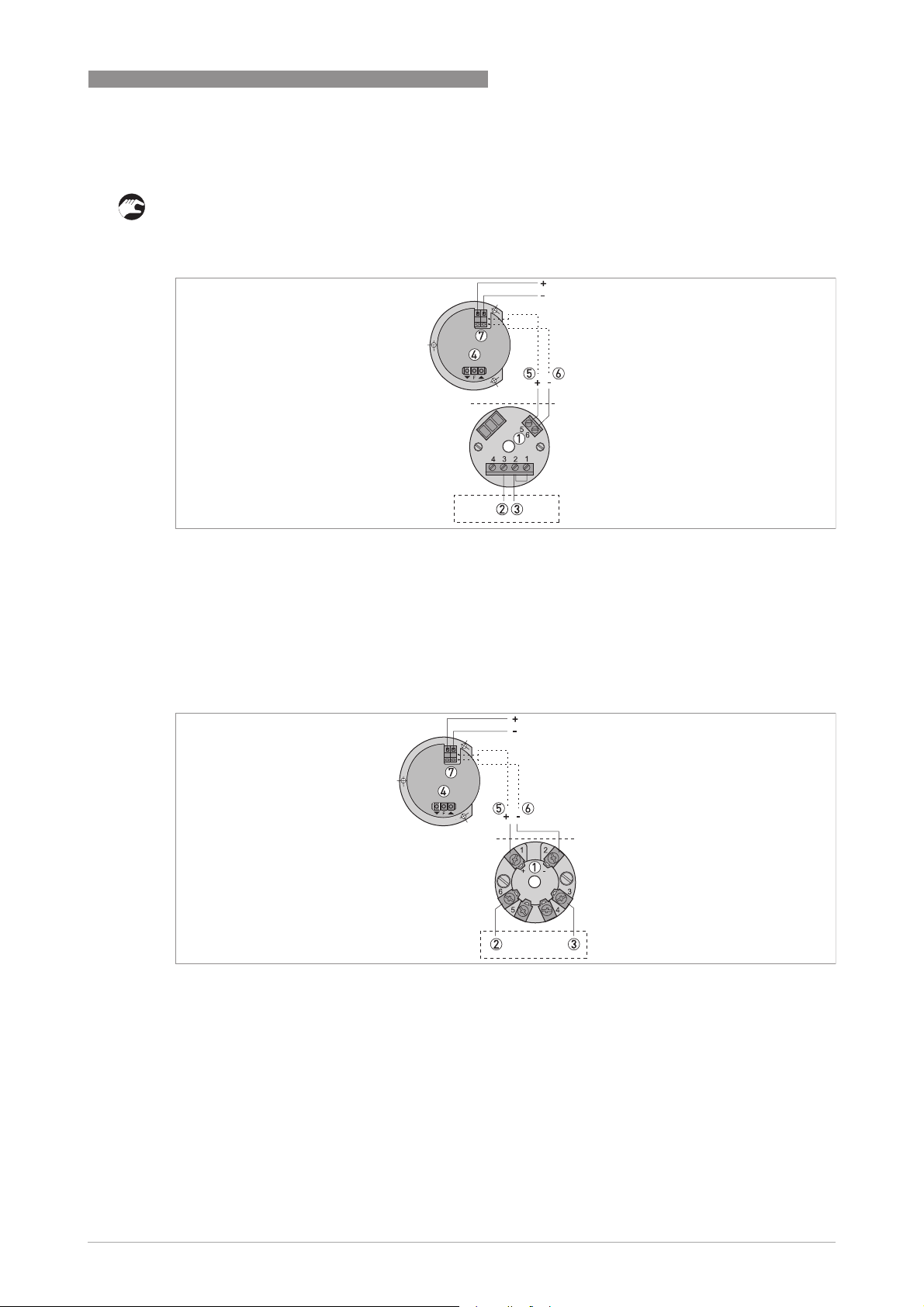
Figure 4-1: Electrical schematic for the 4...20 mA output module
1 Power supply terminals
2 Internal wiring - brown wire
3 Internal wiring - red wire
4 Optional LCD indicator
5 Power supply (+) - if optional LCD connected - red wire
6 Power supply (-) - if optional LCD connected - black wire
7 LCD power supply terminal (10...35 VDC)
Figure 4-2: Electrical schematic for the 4...20 mA + HART output module
1 Power supply terminals
2 Internal wiring - brown wire
3 Internal wiring - red wire
4 Optional LCD indicator
5 Power supply (+) - if optional LCD connected - red wire
6 Power supply (-) - if optional LCD connected - black wire
7 LCD power supply terminal (10...35 VDC)
www.krohne.com10/2012 - 4000347004 - HB BM26 Basic/Adv R04 en
27
Page 28

4 ELECTRICAL CONNECTIONS
Figure 4-3: Electrical schematic for the FOUNDATION™ Fieldbus / PROFIBUS PA module
1 Bus connection terminals
2 Segment coupler
3 Bus termination
4 Internal wiring - orange wire
5 Internal wiring - brown wire
BM 26 BASIC/ADVANCED
For more electrical data, refer to
Technical data: optional analog transmitter
on page 51.
28
www.krohne.com 10/2012 - 4000347004 - HB BM26 Basic/Adv R04 en
Page 29

BM 26 BASIC/ADVANCED
4.2 Optional limit switches
Figure 4-4: Terminal compartment
1 Terminal compartment cover
2 Bistable reed switch
3 Output terminal
• Remove the terminal compartment cover.
• Connect the device to the electrical circuit. Obey the national electrical codes.
ELECTRICAL CONNECTIONS 4
1 2 3
WARNING!
If the switch is set to LOW limit
LOW limit, make sure that switch is open
LOW limitLOW limit
position.
If the switch is set to HIGH limit
HIGH limit, make sure that switch is open
HIGH limitHIGH limit
position.
Figure 4-5: Electrical schema
1 Non-NAMUR version
2 NAMUR version
For more electrical data, refer to
open when the float is below the switch
openopen
open when the float is above the switch
openopen
Technical data: optional limit switches
on page 56.
www.krohne.com10/2012 - 4000347004 - HB BM26 Basic/Adv R04 en
29
Page 30

4 ELECTRICAL CONNECTIONS
4.3 Protection category
For the IP categories of the accessories for the device, refer to the table that follows:
Protection categories according to EN 60529
Equipment housing IP category
Analog transmitter
Non-Ex / Ex i (without indicator) 54
Non-Ex / Ex i (with indicator) 66
Limit switches
Non-Ex / Ex i 66
DANGER!
Make sure the cable gland is watertight.
BM 26 BASIC/ADVANCED
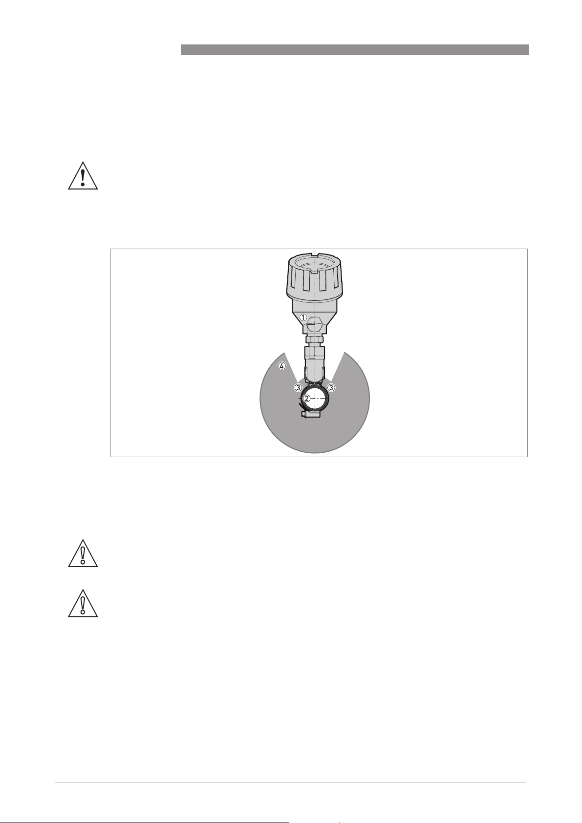
Figure 4-6: Protection category
How to make sure that the electrical installation agrees with the protection category
• Make sure that the gaskets are not damaged.
• Make sure that the electrical cables are not damaged.
• Make sure that the electrical cables agree with the national electrical code.
• The cables are in a loop in front of the device 1 so water cannot enter the housing.
• Tighten the cable glands 2.
• Close unused cable glands with dummy plugs 3.
30
www.krohne.com 10/2012 - 4000347004 - HB BM26 Basic/Adv R04 en
Page 31

BM 26 BASIC/ADVANCED
5.1 Start-up checklist
Check these points before you use the device:
• Are all the wetted components (chamber, flanges and gaskets) resistant to the product in the
tank?
• Does the information on the nameplate agree with the operating data?
• Did you correctly install the device on the tank?
• Do the electrical connections agree with the national electrical codes?
DANGER!
Make sure that the device and the installation agrees with the requirements of the Ex certificate
of compliance.
Start-up procedure
• Attach the drainage plugs or close the drainage cock.
• Slowly open the shut-off valves on the top and bottom process connections.
WARNING!
Risk of damage to the device from shock waves. Open the valves slowly to prevent damange from
water hammer. Use a pressure-limiting valve to prevent damage to the installation.
START-UP 5
WARNING!
The device must have regular servicing to agree with rules and regulations of the site it is
installed on.
WARNING!
High-temperature versions: risk of burns. Do not go too near to the device.
5.2 Operating concept
You can read measurements in several ways:
• Level is indicated by a column of rotating flaps.
• Level is detected by optional limit switches installed at important points adjacent to the
measuring chamber.
• Level is monitored remotely by an optional analog transmitter (2-wire, reed-chain) adjacent
to the measuring chamber. There is a large choice of outputs (4...20 mA, 4...20 mA + HART,
FF and PROFIBUS PA). An LCD indicator option is also available for this transmitter.
CAUTION!
Customer order data is used to calibrate the device. If liquid density changes, the device will not
measure correctly. For more data, refer to Error handling on page 38
.
www.krohne.com10/2012 - 4000347004 - HB BM26 Basic/Adv R04 en
31
Page 32

6 OPERATION
6.1 Local display options
6.1.1 Level indicator column
BM 26 BASIC/ADVANCED
Figure 6-1: Display of data on a indicator column
1 Standard level indicator without a measuring scale
2 Optional measuring scale in m/cm, ft/in or m³
3 Yellow flaps: level of the liquid in the tank
4 Black flaps: empty volume
5 Red flaps: float failure
WARNING!
If the red flaps are shown, either:
•
the float sunk to the bottom of the measuring chamber,
•
the measuring chamber has been completely drained or
•
the product density is less than the value given in the order.
Contact your nearest sales office for advice.
32
www.krohne.com 10/2012 - 4000347004 - HB BM26 Basic/Adv R04 en
Page 33

BM 26 BASIC/ADVANCED
6.1.2 Analog transmitter (option)
General notes
General notes
General notesGeneral notes
The analog transmitter has transmitter modules for analog and digital outputs. The user can do
the configuration of 4...20 mA + HART®, FOUNDATION™ Fieldbus and PROFIBUS PA® modules.
Use the web links in the table that follows to download the software and device description files.
Configuration data for transmitter modules
OPERATION 6
Transmitter Manufacturer User configuration
Yes / No?
4...20 mA INOR No - -
4...20 mA + HART® PR Yes PReset 1 "PRetop 5335" HART DD,
FOUNDATION™
Fieldbus
PROFIBUS PA® PR Yes PReset 1 "5350" GSD files 1
1 Go to the PR electronics website: www.prelectronics.com (Download Center > Software)
PR Yes PReset 1 "5350" DD files 1
Software Device description
files
AMS and DTM files
1
For more data about the configuration of the 4...20 mA + HART®, FOUNDATION™ Fieldbus and
PROFIBUS PA® modules, you can download technical documents from the PR electronics
website: www.prelectronics.com (Download Center > Manuals - Data Sheets - Certificates).
Figure 6-2: Analog transmitter with the optional indicator
1 Non-Ex and Ex i converter housing option
2 4-digit indicator (LCD)
The indications on the LCD are in millimetres by default, but inches and % can also be selected.
The configuration of the indicator is given in the procedures that follow:
WARNING!
Do not open the housing and configure the indicator in a hazardous area.
www.krohne.com10/2012 - 4000347004 - HB BM26 Basic/Adv R04 en
33
Page 34

6 OPERATION
BM 26 BASIC/ADVANCED
Figure 6-3: Get access to the keypad on the indicator board
Equipment needed
• Sheet of stickers with measurement units (mm, inches and %)
• Small slotted tip screwdriver (not supplied)
Get access to the keypad on the indicator board
1 Remove the transmitter housing cover.
2 Remove the screws that hold the indicator board on the housing.
3 Turn the indicator board to use the 3-button keypad ([], [FFFF] and []) on the back of the board
to change the units. Refer to the tables that follow for key functions and the example procedure for configuration of the indicator.
4 Attach the indicator board to the housing.
5 Put the sticker with the correct measurement unit over the default units under the indicator
screen.
6 Attach the transmitter housing cover.
34
www.krohne.com 10/2012 - 4000347004 - HB BM26 Basic/Adv R04 en
Page 35

BM 26 BASIC/ADVANCED
Figure 6-4: Back and front view of the indicator
1 Back of the indicator board (3-button keypad at the bottom)
2 Front of the indicator board (span range menu in program mode shown)
Key functions
Key Menu level Function level
[FFFF] (3 seconds) Access to program mode -
[FFFF] (1 second) Access to the function. Confirm the new parameter and go back
[] (down) Move down the list of functions Select parameter / decrease the value of
[] (up) Move up the list of functions Select parameter / increase the value of
[] + [] Escape - go back to the indication Escape - go back to the menu 1
1 This does not confirm that you selected a new parameter
OPERATION 6
to the menu.
the parameter. Push [] intermittently
to decrease the value in increments of
0.1. Push [] continuously to decrease
the value in increments of 1.
the parameter. Push [] intermittently
to increase the value in increments of
0.1. Push [] continuously to increase
the value in increments of 1.
www.krohne.com10/2012 - 4000347004 - HB BM26 Basic/Adv R04 en
35
Page 36

6 OPERATION
Menu overview
Function Function description Range/Selection list Default
BM 26 BASIC/ADVANCED
Decimal Point (dP) Push [] or [] to select
the decimal point position.
Push [FFFF] to confirm.
Zero point (ZErO) Push [] or [] to select
the minimum value. Push
[FFFF] to confirm.
Span range (SPAn) Push [] or [] to select
the maximum value. Push
[FFFF] to confirm.
Input current limit (Li) Do not use. n/a 0
Filter (FiLt) Do not use. n/a 2
Resolution (riS) Do not use. n/a 1
0…3 1
-1999…+9999 0.0
-1999…+9999 100.0
Example procedure: Change the indicator units from mm to %
• Push [FFFF] for 3 seconds (button on the back of the indicator board) to access Program mode
i In program mode dP
• Push [] 1 time to get to the zero point (ZErO
dP is displayed.
dPdP
ZErO) function.
ZErOZErO
• Push [FFFF] to access the span range parameter. Make sure that the value is 0.0. Push [] + []
(Escape) to go back to the menu.
• Push [] 1 time to get to the span range (SPAn
SPAn) function.
SPAnSPAn
• Push [FFFF] to access the span range parameter.
Program mode.
Program modeProgram mode
i The current value is 600 (example value).
• Push [] to decrease the value to 100.
• Push [FFFF] to confirm the parameter and go back to the menu.
• Push [] + [] (Escape) to go back to the indication.
i The indication will display a value between 0 and 100 based on a current output of 4...20 mA.
• Put a new sticker (%) on the front of the indicator board.
36
www.krohne.com 10/2012 - 4000347004 - HB BM26 Basic/Adv R04 en
Page 37

BM 26 BASIC/ADVANCED
6.2 Errors
6.2.1 Error indication
Indicator column
OPERATION 6
Figure 6-5: Error displayed on the indicator column
1 Indicator column (rotating flaps)
2 Red flaps: float failure
Analog transmitter
-OL OL
Figure 6-6: Error displayed on the optional LCD indicator for the analog transmitter
1 Error message if current output is < 3.6 mA
2 Error message if current output is > 22 mA
Limit switches
Limit switches can be used to indicate error conditions (Float failure, level detection etc.). For
more data, refer to
Optional limit switch
on page 23.
www.krohne.com10/2012 - 4000347004 - HB BM26 Basic/Adv R04 en
37
Page 38

6 OPERATION
6.2.2 Error handling
Indicator column
Float failure The red flaps at the bottom of the
The level of the liquid is at or
above the maximum level, but
the indicator column doe not
indicate that level has
reached its maximum limit
yet.
The indicator column
indicates that the liquid is at
or below the minimum level,
but the level of the liquid is
still above the minimum limit.
The level of the liquid is below
the maximum level, but the
indicator column indicates
that level has already reached
its maximum limit.
The indicator column is not
yet at the minimum level, but
the level of the liquid is at or
below the minimum limit.
BM 26 BASIC/ADVANCED
Error Description Corrective action
indicator column are shown. The
float has sunk to the bottom of the
measuring chamber.
The density of the liquid is lower
than the value given in the
customer order data. The float is
too low in the liquid.
The density of the liquid is lower
than the value given in the
customer order data. The float is
immersed more than it should be.
The density of the liquid is higher
than the value given in the
customer order data. The float is
not sufficiently immersed.
The density of the liquid is higher
than the value given in the
customer order data. The float is
immersed more than it should be.
Make sure the measuring chamber
has not been completely drained.
Make sure the true density of the
liquid corresponds to the value
given in the order data. Contact
your local sales office to make sure
that the float is for the correct
density range.
If the float is damaged or corroded,
it is necessary to replace the float.
Order a new float from your local
sales office. Isolate the measuring
chamber and drain the liquid.
Remove the bottom plate flange
and the float. If your device is a
basic version, you will only be able
to remove the float if it has the
1¼ NPT connection at the bottom
of the measuring chamber
Make sure that the density of the
liquid is stable. Contact your local
sales office for advice.
Make sure that the density of the
liquid is stable. Contact your local
sales office for advice.
Make sure that the density of the
liquid is stable. Contact your local
sales office for advice.
Make sure that the density of the
liquid is stable. Contact your local
sales office for advice.
38
www.krohne.com 10/2012 - 4000347004 - HB BM26 Basic/Adv R04 en
Page 39

BM 26 BASIC/ADVANCED
Error Description Corrective action
Analog transmitter
Optional LCD indicator status: OLCurrent output is more than 22 mA
Optional LCD indicator status:
-OL
The level of the liquid is at or
above the maximum level, but
the analog transmitter output
doe not indicate that level has
reached its maximum limit
yet.
The analog transmitter output
indicates that the liquid is at
or below the minimum level,
but the level of the liquid is
still above the minimum limit.
The level of the liquid is below
the maximum level, but the
analog transmitter output
indicates that level has
already reached its maximum
limit.
The analog transmitter output
is not yet at the minimum
level, but the level of the
liquid is at or below the
minimum limit.
(more than 20 mA, if this option is
selected in the indicator). Overfill.
The level of the liquid is above the
maximum limit (if the indicator is
configured for level indication).
Current output is more than 22 mA
(more than 20 mA, if this option is
selected in the indicator). The
analog transmitter has been
moved. A value more than 20 mA
no longer represents the
maximum limit.
Current output is more than 22 mA
(more than 20 mA, if this option is
selected in the indicator). The
analog transmitter is defective. A
value more than 20 mA no longer
represents the maximum limit.
Current output is less than 3.6 mA
(less than 4 mA, if this option is
selected in the indicator). The level
of the liquid is below the minimum
limit (if the indicator is configured
for level indication).
Current output is less than 3.6 mA
(less than 4 mA, if this option is
selected in the indicator). The
analog transmitter has been
moved. A value less than 4 mA no
longer represents the minimum
limit.
Current output is less than 3.6 mA
(less than 4 mA, if this option is
selected in the indicator). The
analog transmitter is defective. A
value less than 4 mA no longer
represents the minimum limit.
The density of the liquid is lower
than the value given in the
customer order data. The float is
too low in the liquid.
The density of the liquid is lower
than the value given in the
customer order data. The float is
too low in the liquid.
The density of the liquid is higher
than the value given in the
customer order data. The float is
too high in the liquid.
The density of the liquid is higher
than the value given in the
customer order data. The float is
too high in the liquid.
OPERATION 6
Lower the level of liquid below the
maximum limit.
Contact your local sales office for
advice.
Contact your local sales office for
advice.
Increase the level of liquid until it is
above the minimum limit.
Contact your local sales office for
advice.
Contact your local sales office for
advice.
Make sure that the density of the
liquid is stable. Contact your local
sales office for advice.
Make sure that the density of the
liquid is stable. Contact your local
sales office for advice.
Make sure that the density of the
liquid is stable. Contact your local
sales office for advice.
Make sure that the density of the
liquid is stable. Contact your local
sales office for advice.
www.krohne.com10/2012 - 4000347004 - HB BM26 Basic/Adv R04 en
39
Page 40

6 OPERATION
Limit switch
The limit switch is in highhigh (maximum) position and
set to HIGH limit
HIGH limit. Status
HIGH limitHIGH limit
OPEN
OPEN.
OPENOPEN
The limit switch is in low-low
(minimum) position and set to
LOW limit
LOW limit. Status OPEN
LOW limitLOW limit
The limit switch is in the float
failure position and set to
LOW limit
LOW limit. Status OPEN
LOW limitLOW limit
The level switch does not
detect the minimum limit
correctly.
The level switch does not
detect the maximum limit
correctly.
BM 26 BASIC/ADVANCED
Error Description Corrective action
OPEN.
OPENOPEN
OPEN.
OPENOPEN
Overfill? The level of the liquid is at
or above the maximum limit (if the
indicator is configured for level
indication).
Tank empty? The level of the liquid
is at or below the minimum limit (if
the indicator is configured for level
indication).
Float failure. The float has sunk to
the bottom of the measuring
chamber.
The limit switch (set to LOW limit
is open (off), but the level of the
liquid is still above the minimum
limit. The density of the liquid is
lower than the value given in the
customer order data.
The limit switch (set to LOW limit
is not yet open (off), but the level of
the liquid is at or below the
minimum limit. The density of the
liquid is higher than the value given
in the customer order data.
The level of the liquid is at or above
the maximum level, but the limit
switch (set to HIGH limit
open (off). The density of the liquid
is lower than the value given in the
customer order data.
The level of the liquid is below the
maximum level, but the limit
switch (set to HIGH limit
(off). The density of the liquid is
higher than the value given in the
customer order data.
HIGH limit) is not yet
HIGH limitHIGH limit
HIGH limit) is open
HIGH limitHIGH limit
LOW limit)
LOW limitLOW limit
LOW limit)
LOW limitLOW limit
Lower the level of liquid below the
maximum limit.
Increase the level of liquid until it is
above the minimum limit.
It is necessary to replace the float.
Order a new float from your local
sales office. Isolate the measuring
chamber and drain the liquid.
Remove the bottom plate flange
and the float. If your device is a
basic version, you will only be able
to remove the float if it has the
1¼ NPT connection at the bottom
of the measuring chamber.
Make sure that the density of the
liquid is stable. Recalculate the
liquid density and repeat the
installation procedure for the limit
switch.
40
www.krohne.com 10/2012 - 4000347004 - HB BM26 Basic/Adv R04 en
Page 41

BM 26 BASIC/ADVANCED
7.1 Periodic maintenance
This device does not normally need maintenance. If the liquid is contaminated or build-up of
deposits is possible, we recommend that you flush the device regularly.
WARNING!
Pressure Equipment Directive 97/23/EC data
Pressure Equipment Directive 97/23/EC data
Pressure Equipment Directive 97/23/EC dataPressure Equipment Directive 97/23/EC data
The device must be regularly serviced to conform to the rules and regulations applicable to the
site that it is installed on.
WARNING!
Follow accident prevention regulations carefully when working with pressurized tanks and
dangerous chemical products.
How to flush the device
• Open the drain plug or drain valve.
• Flush the chamber.
WARNING!
If you remove the float, close the shut-off valves.
SERVICE 7
Float removal procedure (not for basic version without 1¼¨ plug)
• Close the shut-off valves.
• Remove the bottom process connection counter-flange or plug.
• Remove and clean the float.
7.2 Keep the device clean
DANGER!
If you rub the anti-freeze cover option with a dry cloth, there is a risk of electrostatic discharge.
Clean the anti-freeze cover option only with a damp cloth.
7.3 How to replace device components
7.3.1 Service warranty
Maintenance is not necessary for most applications.
Servicing by the customer is limited by warranty to
• The removal and installation of switches. For more data, refer to Optional limit switch
page 23.
• The removal and installation of the float. For more data, refer to Remove all packing before
installation
installation on page 16.
installationinstallation
Optional limit switch on
Optional limit switchOptional limit switch
Remove all packing before
Remove all packing before Remove all packing before
The indicator column and switches can be removed under process conditions.
Use only KROHNE-authorized service staff to repair the device.
www.krohne.com10/2012 - 4000347004 - HB BM26 Basic/Adv R04 en
41
Page 42

7 SERVICE
7.4 Availability of services
The manufacturer offers a range of services to support the customer after expiration of the
warranty. These include repair, maintenance, technical support and training.
INFORMATION!
For more precise information, please contact your local sales office.
7.4.1 General notes
We supply spare parts and accessories for this device. When you order a spare part or
accessory, please give the reference numbers that follow:
7.4.2 List of spare parts
For the measuring chamber:
• Floats
BM 26 BASIC/ADVANCED
Float designation Product density Part number
[kg/l] [lb/ft³]
Basic version
Float 1 0.8...1.19 49.9...74.3 F3187980500
Advanced version
Float 1 0.58...0.7 36.2...43.7 F3187981900
Float 2 0.7...0.99 43.7...61.8 F3187981600
Float 3 0.99...2 61.8...124.8 F3187980900
For the analog transmitter:
• Transmitter modules. For more data, refer to
Order code
on page 84.
INFORMATION!
Supply this data when you order spare parts:
•
Device serial number
•
Manufacturer's order number
•
Floats only: Float material (on the float data sticker at the bottom of the indicator column)
•
Floats only: Maximum allowable pressure, Ps and test pressure, Pt (on the float data sticker)
42
www.krohne.com 10/2012 - 4000347004 - HB BM26 Basic/Adv R04 en
Page 43

BM 26 BASIC/ADVANCED
7.4.3 List of accessories
For the measuring chamber:
• Limit switch, non-NAMUR
• Limit switch, NAMUR
INFORMATION!
For more data on the limit switches, refer to Technical data: optional limit switches on page 56
For the 2-wire, loop-powered analog transmitter:
• AS 24 power supply unit 24 VDC / 230 VAC
• AS 24 power supply unit 24 VDC / 110 VAC
• PROF SI 24075 intrinsically-safe power supply unit (with galvanic separation)
• C 95 Basic univeral power supply (Panel mount, 2 relays, 4-digit local indicator and non-Ex)
• C 95 Basic univeral power supply (Panel mount, 2 relays, 4…20 mA output, 4-digit local
indicator and non-Ex)
SERVICE 7
.
INFORMATION!
For more data on the C 95 power supply, refer to the technical datasheet in our download centre.
7.5 Availability of services
The manufacturer offers a range of services to support the customer after expiration of the
warranty. These include repair, maintenance, technical support and training.
INFORMATION!
For more precise information, please contact your local sales office.
www.krohne.com10/2012 - 4000347004 - HB BM26 Basic/Adv R04 en
43
Page 44

7 SERVICE
7.6 Returning the device to the manufacturer
7.6.1 General information
This device has been carefully manufactured and tested. If installed and operated in accordance
with these operating instructions, it will rarely present any problems.
CAUTION!
Should you nevertheless need to return a device for inspection or repair, please pay strict
attention to the following points:
•
Due to statutory regulations on environmental protection and safeguarding the health and
safety of our personnel, manufacturer may only handle, test and repair returned devices that
have been in contact with products without risk to personnel and environment.
•
This means that the manufacturer can only service this device if it is accompanied by the
following certificate (see next section) confirming that the device is safe to handle.
CAUTION!
If the device has been operated with toxic, caustic, flammable or water-endangering products,
you are kindly requested:
•
to check and ensure, if necessary by rinsing or neutralising, that all cavities are free from
such dangerous substances,
•
to enclose a certificate with the device confirming that is safe to handle and stating the
product used.
BM 26 BASIC/ADVANCED
44
www.krohne.com 10/2012 - 4000347004 - HB BM26 Basic/Adv R04 en
Page 45

BM 26 BASIC/ADVANCED
7.6.2 Form (for copying) to accompany a returned device
Company: Address:
Department: Name:
Tel. No.: Fax No.:
The meter enclosed, type:
Manufacturer's Order or Serial No.:
SERVICE 7
has been operated with the following liquid:
Because this liquid is: hazardous to water
toxic
caustic
flammable
We have checked that all cavities in the unit are free from
such substances.
We have flushed out and neutralized all cavities in the unit.
We herewith confirm that in returning this unit there is no risk to man or environment through any
residual liquid contained in it.
Date: Company stamp:
Signature:
7.7 Disposal
CAUTION!
Disposal must be carried out in accordance with legislation applicable in your country.
www.krohne.com10/2012 - 4000347004 - HB BM26 Basic/Adv R04 en
45
Page 46

8 TECHNICAL DATA
8.1 Measuring principle
The device operates on the principle of communicating tubes. The measuring chamber is
connected adjacent to the tank. The process conditions in the measuring chamber are the same
as those of the tank.
A float is in the measuring chamber. The float contains magnets that rotate the flaps in the
indicator column and operate the optional limit switches and analog transmitter on the side of
the measuring chamber. The position of the magnets does not correspond to the level of liquid
so the scale is offset at the factory to take into account this difference. The offset of the magnets
depends on the liquid density. Refer to the illustration that follows:
Magnet offset
BM 26 BASIC/ADVANCED
Figure 8-1: Magnet offset
1 True level of the liquid
2 Top of the float magnet (which corresponds to the level shown on the indicator column)
3 Difference (offset) between the true level of the liquid and the top of the float magnet (depends on the liquid density)
4 Indicator column of yellow/black rotating flaps (with the optional scale)
46
www.krohne.com 10/2012 - 4000347004 - HB BM26 Basic/Adv R04 en
Page 47
BM 26 BASIC/ADVANCED
8.2 Technical data: general information
INFORMATION!
•
The following data is provided for general applications. If you require data that is more
relevant to your specific application, please contact us or your local sales office.
•
Additional information (certificates, special tools, software,...) and complete product
documentation can be downloaded free of charge from the website (Download Center).
Measuring system
Measuring principle Bypass level indicator (principle of communicating tubes). A float in
Application range Level indication of liquids for
Measured value
Measured value
Measured valueMeasured value
Primary measured value Level of the float magnets in the measuring chamber
Secondary measured value Level and volume of the liquid in the measuring chamber
the measuring chamber (Ø42 mm / 1.7¨) is magnetically-coupled to a
mechanical level indicator.
low-pressure applications and in
storage tanks
TECHNICAL DATA 8
Basic Advanced
Level indication of liquids in
applications up to 40 barg /
580 psig
Design
Options and variants
Options and variants
Options and variantsOptions and variants
Variants Lateral / lateral process connections
Axial / axial process connections
Top lateral / bottom axial process connections
Top axial / bottom lateral process connections
Options Support bracket (a wall support for long bypass level indicators)
Analog transmitter without display (converter with 4...20 mA,
4...20 mA + HART®, PROFIBUS PA or FF output module mounted at
the top or bottom of the reed chain) 1
Analog transmitter with display (4...20 mA or 4...20 mA + HART®
converter mounted at the top or bottom of the reed chain)
1¼¨ threaded cover (for
installation/ removal of the float)
Anti-freeze cover for glass indicator tube (when the ambient
temperature is -40...-20°C / -40...-4°F)
- OPTIFLEX 1300 C with Ø2 mm
- OPTIFLEX 1300 C (if DN40 PN40
- OPTIWAVE 7300 C (if welded
Accessories Bistable limit switches (NAMUR or non-NAMUR)
Measuring range (ML) 0.3…5.3 m / 1…17.4 ft 0.3…5.3 m / 1…17.4 ft
-
single cable probe (if ½ BSPP top
axial connection is selected)
top axial connection is selected )
antenna or DN40 PN40 top axial
connection is selected)
(longer on request)
www.krohne.com10/2012 - 4000347004 - HB BM26 Basic/Adv R04 en
47
Page 48

8 TECHNICAL DATA
Display and user interface
Display and user interface
Display and user interfaceDisplay and user interface
Display Indicator column with magnetically-coupled yellow/black rotating
Float failure indication Red/black rotating flaps at the bottom of the indicator column
Scale marking options No scale; m + cm; ft + inches; %
Measuring accuracy
Accuracy ±10 mm / 0.4¨
Repeatability ±10 mm / 0.4¨ (when density is constant)
Maximum rate of change 2 m/minute / 6.5 ft/minute
Operating conditions
Temperature
Temperature
TemperatureTemperature
Process -40…+150°C/ -40…+300°F
Ambient temperature -40…+80°C/ -40…+176°F (Ex: see supplementary instructions or
Storage temperature -50…+80°C/ -58…+176°F
Pressure
Pressure
PressurePressure
Max. allowable operating
pressure
Chemical properties
Chemical properties
Chemical propertiesChemical properties
Density 0.8…1.19 kg/l / 49.9...68.7 lb/ft³ 0.58…2 kg/l / 36.2...124.8 lb/ft³
Viscosity ≤ 5000 mPas / ≤ 3.360 lb/ft³
Other conditions
Other conditions
Other conditionsOther conditions
Ingress protection IP 68
Basic Advanced
flaps; no indicator column
(Ex: see supplementary
instructions or approval
certificates)
approval certificates)
16 barg / 232 psig (according to
the length of the measuring
chamber. Also refer to
Guidelines for maximum
operating pressure
on page 76.)
BM 26 BASIC/ADVANCED
-40...+300°C/ -40…+570°F
(Ex: see supplementary
instructions or approval
certificates)
40 barg / 580 psig (according to
the flange pressure rating. Also
refer to
operating pressure
Guidelines for maximum
on page 76.)
48
Installation conditions
Recommendations Mount vertically on the side of tanks
Fit isolation valves on process connections to permit maintenance of
the bypass chamber (optional)
Dimensions and weights Refer to "Technical data: Dimensions and weights"
Materials
Chamber Standard: Stainless steel (1.4404 / 316L)
- Option: Hastelloy® C-276 2
Float Standard: Stainless steel
(1.4404 / 316L)
- Option: Hastelloy®
Indicator rail Stainless steel
Indicator tube Pyrex® glass (glass tube with a true hermetic seal) 3
Scale (option) Stainless steel
www.krohne.com 10/2012 - 4000347004 - HB BM26 Basic/Adv R04 en
Stainless steel (1.4404 / 316L);
Titanium (for data on material
selection, refer to
78)
Floats
on page
Page 49

BM 26 BASIC/ADVANCED
Process fitting Standard: Stainless steel (1.4404 / 316L)
Gaskets Teflon® tape 4 Standard: Aramid; Teflon® tape
Braid insulation - Ceramic fibre (insulation
Anti-freeze cover for glass
indicator tube (option)
Process connections
Threaded pipes ½...¾ NPT; G ½...¾
Smooth pipes, 10S ½¨; ¾¨ in 10S
Flange version
Flange version
Flange versionFlange version
EN DN15…40 (Form B1) in PN16 / 40 DN15…50 (Form B1, C or E) in
ASME ½…1½¨ (RF) in 150 lb / 300 lb ½…1½¨ (RF) in 150 lb / 300 lb;
TECHNICAL DATA 8
Basic Advanced
- Option: Hastelloy® C-276 (for the
wetted parts of EN loose flanges
only)
- Options: Graphite; PTFE
between the indicator column
and the measuring chamber
when the process temperature is
+100...+300°C / +210...+570°F)
Plexiglas®
PN16 / 40;
DN15…50 (Form B1, C or E) in
PN63 / 100; others are available
on request
Note: Hastelloy® C-276 flange
connections are only available as
loose flanges with form B1
others are available on request
Drain and vent connections
Drain options
Drain options
Drain optionsDrain options
Thread Standard: cover with 3/8 NPT
Flange - Options: all process connection
Vent options
Vent options
Vent optionsVent options
Thread Standard: without (convex cap) Standard: 3/8 NPT plug
Flange - Options: all process connection
plug
Option: cover with 1¼ NPT plug Options: on page 66
Option: cover with 3/8 NPT plug Options: flange with ½ NPT plug;
Standard: flange with ½ NPT plug
options
flange with G ½ plug; DN40 top
flange (for radar or TDR level
transmitter) with ½ NPT lateral
vent plug; welded antenna with
½ NPT lateral vent plug; ½ BSPP
screw connection for
OPTIFLEX 1300 C and Ø2 mm
single cable probe, with ½ NPT
lateral vent plug; all process
connection options
options
www.krohne.com10/2012 - 4000347004 - HB BM26 Basic/Adv R04 en
49
Page 50

8 TECHNICAL DATA
Power supply
Limit switches Refer to "Technical data: optional level switches"
Analog transmitter Refer to "Technical data: optional analog transmitter"
Input and output
Parameter Level detection or indication
Output signal Refer to "Technical data: optional level switches" and "Technical
Approvals and certification
CE CE marking not applicable (not
Explosion protection
Explosion protection
Explosion protectionExplosion protection
ATEX II 1 G or II 1/2 G (measuring chamber)
Other standards and approvals
Other standards and approvals
Other standards and approvalsOther standards and approvals
PED Not subject to PED test
Vibration resistance Vibration class 4M4 according to EN 60721-3-4
Construction code Standard: "CODAP® 2010"
1 HART® is a registered trademark of the HART Communication Foundation
2 Hastelloy® is a registered trademark of Haynes International, Inc.
3 Pyrex® is a registered trademark of Corning, Inc.
4 Teflon® is a registered trademark of E.I. du Pont de Nemours and Company
BM 26 BASIC/ADVANCED
Basic Advanced
data: optional analog transmitter"
subject to PED test
requirements)
Refer also to approvals in "Technical data: optional level switches"
and "Technical data: optional analog transmitter"
requirements
Option: NACE MR0175 / ISO 15156
On request: EN 13445
This device fulfils the statutory
requirements of the EC
directives. The manufacturer
certifies successful testing of the
product by applying the CE mark.
Pressure Equipment Directive
97/23/EC in conjunction with
CODAP® 2010
50
www.krohne.com 10/2012 - 4000347004 - HB BM26 Basic/Adv R04 en
Page 51

BM 26 BASIC/ADVANCED
8.3 Technical data: optional analog transmitter
Analog output or HART® communication modules
Module output 4...20 mA 4...20 mA / HART®
TECHNICAL DATA 8
Order code xF45xBxxxxx
(without LCD indicator)
xF45xExxxxx
(with LCD indicator)
xF45xWxxxxx
(without LCD indicator)
xF45xGxxxxx
(with LCD indicator)
Measuring system
Measuring principle A reed resistor chain that is magnetically actuated by a magnetic
Primary measured value Resistance
Secondary measured value Level and volume of the liquid in the measuring chamber
float in the BM 26 measuring chamber
Design
Description of device Resistance reed chain with 2-wire loop-powered transmitter module
Description of transmitter
module
Options Converter position - The customer must specify the position of the
Accessories SU 600 power supply unit 24 V
Display and user interface
Display and user interface
Display and user interfaceDisplay and user interface
Display Standard: none
Functions Display of level in mm; inches; %
Display 2-wire loop-powered indicator
Operation Selectable number of decimals,
attached adjacent to the measuring chamber of the bypass level
indicator. Changes in resistance are converted to an output signal via
a transmitter module.
Changes in resistance are
converted to analog current
signals.
converter at the top or the bottom of the analog transmitter
LCD indicator
SU 600 power supply unit 24 V with integrated Ex ia barrier
PROF SI 24075 intrinsically-safe power supply unit (with galvanic
separation)
C 95 Basic universal power supply (Panel mount, 2 relays, 4-digit
local indicator and non-Ex)
C 95 Basic universal power supply (Panel mount, 2 relays, 4…20 mA
output, 4-digit local indicator and non-Ex)
Option: 2-wire loop-powered LCD
indicator
(stickers for optional units of
measure are supplied with the
device). 4-digit LCD with minus
sign, 3-button keypad.
4-digit LCD with minus sign,
3-button keypad
0 to 3. Open the housing to
configure the device.
Changes in resistance are
converted to analog or digital
current signals. Up to 15
transmitters can be connected to
a network that agrees with the
HART® communication protocol.
Option: 2-wire loop-powered LCD
indicator
Display of level in mm; inches; %
(stickers for optional units of
measure are supplied with the
device). 4-digit LCD with minus
sign, 3-button keypad.
2-wire loop-powered indicator
4-digit LCD with minus sign,
3-button keypad
Selectable number of decimals,
0 to 3. Open the housing to
configure the device.
www.krohne.com10/2012 - 4000347004 - HB BM26 Basic/Adv R04 en
51
Page 52

8 TECHNICAL DATA
Module output 4...20 mA 4...20 mA / HART®
BM 26 BASIC/ADVANCED
Order code xF45xBxxxxx
(without LCD indicator)
xF45xExxxxx
(with LCD indicator)
xF45xWxxxxx
(without LCD indicator)
xF45xGxxxxx
(with LCD indicator)
Measuring accuracy
Accuracy ±10 mm / 0.4¨ (when density is
constant)
≤ ±0.1% of span
Temperature coefficient ≤ ±0.01% of span/°C ≤ ±0.005% of span/°C
EMC immunity influence < ±0.1% of span < ±0.1% of span
±10 mm / 0.4¨ (when density is
constant)
≤ ±0.05% of span
Operating conditions
Temperature
Temperature
TemperatureTemperature
Operating temperature,
transmitter module
Operating temperature, LCD
indicator
Pressure
Pressure
PressurePressure
Operating pressure Atmospheric pressure
Other conditions
Other conditions
Other conditionsOther conditions
Warm-up time 5...10 minutes 30 s
Response time 1.5 s 1....60 s 2
Protection category Transmitter housing without LCD indicator: IP 54
-40…+85°C/ -40…+185°F, if there is insulation around the
measuring chamber, specify the temperature in the order. Do not put
insulation around the transmitter housing.
-20…+70°C/ -4…+158°F 1
Transmitter housing with LCD indicator: IP 66
Installation conditions
Notes The analog transmitter is calibrated at the factory and attached to the
Dimensions and weight Refer to the "Technical data: Dimensions and weights" section
measuring chamber before delivery
Materials
Housing Polyester-coated aluminium
Reed-chain tube Stainless steel
Clamp Stainless steel
52
www.krohne.com 10/2012 - 4000347004 - HB BM26 Basic/Adv R04 en
Page 53

BM 26 BASIC/ADVANCED
Module output 4...20 mA 4...20 mA / HART®
TECHNICAL DATA 8
Order code xF45xBxxxxx
(without LCD indicator)
xF45xExxxxx
(with LCD indicator)
xF45xWxxxxx
(without LCD indicator)
xF45xGxxxxx
(with LCD indicator)
Electrical connections
Power supply
Power supply
Power supplyPower supply
Voltage Non-Ex:
LCD indicator; voltage drop 2.5 V 2.5 V
Cable entry M20 × 1.5
Intrinsically-safe circuit data for
Ex ia-approved devices
Non-Ex:
Non-Ex:Non-Ex:
12…35 VDC 8…30 VDC
Ex ia, without LCD indicator:
Ex ia, without LCD indicator:
Ex ia, without LCD indicator:Ex ia, without LCD indicator:
Refer to supplementary instructions or approval certificates
Ex ia, with LCD indicator:
Ex ia, with LCD indicator:
Ex ia, with LCD indicator:Ex ia, with LCD indicator:
Refer to supplementary
instructions or approval
certificates
Refer to supplementary instructions or approval certificates
-
Input and output
Current output
Current output
Current outputCurrent output
Output range 4…20 mA
Error signal Upper value, selectable
21.6 mA 23 mA
Lower value, selectable
3.5 mA
HART
HART®
HARTHART
Description - HART® protocol via passive
Multidrop operation - Yes, current output = 4 mA
current output
Multidrop address (1...15)
adjustable
www.krohne.com10/2012 - 4000347004 - HB BM26 Basic/Adv R04 en
53
Page 54

8 TECHNICAL DATA
Module output 4...20 mA 4...20 mA / HART®
BM 26 BASIC/ADVANCED
Order code xF45xBxxxxx
(without LCD indicator)
xF45xExxxxx
(with LCD indicator)
xF45xWxxxxx
(without LCD indicator)
xF45xGxxxxx
(with LCD indicator)
Approvals and certifications
CE This device fulfils the statutory requirements of the EC directives.
Explosion protection
Explosion protection
Explosion protectionExplosion protection
ATEX - without LCD indicator II 1 G Ex ia IIC T4...T6 II 1 G Ex ia IIC T4 or T6
ATEX - with LCD indicator II 1 G Ex ia IIC T5 -
Other standards and approvals
Other standards and approvals
Other standards and approvalsOther standards and approvals
EMC Electromagnetic Compatibility
Vibration resistance Vibration class 4M4 according to EN 60721-3-4
NAMUR NAMUR NE 43 4
1 If the operating temperature is not in these limits, the display switches off. The transmitter module continues to oper-
ate above and below this temperature range.
2 This value is programmable
3 Electromagnetic Compatibility of Industrial and Laboratory Control Equipment
4 Standardization of the Signal Level for the Failure Information of Digital Transmitters
The manufacturer certifies successful testing of the product by
applying the CE mark.
Directive 2004/108/EC in
conjunction with EN 61326-1
(2006)
Electromagnetic Compatibility
Directive 2004/108/EC in
conjunction with EN 61326-1
(2006)
NAMUR NE 21
3
Fieldbus modules
Module output FOUNDATION™ Fieldbus PROFIBUS PA
Order code xF45xDxxxxx (PR) xF45xXxxxxx (PR)
Measuring system
Measuring principle A reed resistor chain that is magnetically actuated by a magnetic
Primary measured value Resistance
Secondary measured value Level and volume of the liquid in the measuring chamber
float in the BM 26 measuring chamber
Design
Description of device Resistance reed chain with 2-wire loop-powered transmitter module
Description of transmitter
module
Options Converter position 1
Accessories SU 600 power supply unit 24 V
attached adjacent to the measuring chamber of the bypass level
indicator. Changes in resistance are converted to an output signal via
a transmitter module.
Changes in resistance are
converted to signals that agree
with the FF communication
protocol.
Changes in resistance are
converted to signals that agree
with the PROFIBUS PA
communication protocol.
54
www.krohne.com 10/2012 - 4000347004 - HB BM26 Basic/Adv R04 en
Page 55

BM 26 BASIC/ADVANCED
Module output FOUNDATION™ Fieldbus PROFIBUS PA
Order code xF45xDxxxxx (PR) xF45xXxxxxx (PR)
Display and user interface
Display and user interface
Display and user interfaceDisplay and user interface
Display None
Measuring accuracy
Accuracy ±10 mm / 0.4¨ (when density is constant)
Operating conditions
Temperature
Temperature
TemperatureTemperature
Operating temperature,
transmitter module
Pressure
Pressure
PressurePressure
Operating pressure Atmospheric pressure
Other conditions
Other conditions
Other conditionsOther conditions
Protection category Transmitter housing without LCD indicator: IP 54
TECHNICAL DATA 8
-40…+85°C / -40…+185°F, if there is insulation around the
measuring chamber, specify the temperature in the order. Do not put
insulation around the transmitter housing.
Transmitter housing with LCD indicator: IP 66
Installation conditions
Notes The analog transmitter is calibrated at the factory and attached to the
Dimensions and weight Refer to the "Technical data: Dimensions and weights" section
measuring chamber before delivery
Materials
Housing Polyester-coated aluminium
Reed-chain tube Stainless steel
Clamp Stainless steel
Electrical connections
Power supply
Power supply
Power supplyPower supply
Voltage Non-Ex:
Cable entry M20 × 1.5
Intrinsically-safe circuit data for
Ex ia-approved devices
PROFIBUS PA
PROFIBUS PA
PROFIBUS PAPROFIBUS PA
Description - PROFIBUS PA protocol Profile
FOUNDATION Fieldbus
FOUNDATION Fieldbus
FOUNDATION FieldbusFOUNDATION Fieldbus
Description FOUNDATION Fieldbus protocol -
Non-Ex:
Non-Ex:Non-Ex:
9...32 VDC
Ex ia:
Ex ia:
Ex ia:Ex ia:
Refer to supplementary instructions or approval certificates
Refer to supplementary instructions or approval certificates
A&B, ver.3.0 (EN 50170 vol.2)
www.krohne.com10/2012 - 4000347004 - HB BM26 Basic/Adv R04 en
55
Page 56

8 TECHNICAL DATA
Module output FOUNDATION™ Fieldbus PROFIBUS PA
Order code xF45xDxxxxx (PR) xF45xXxxxxx (PR)
Approvals and certification
CE This device fufills the statutory requirements of the EC directives.
Explosion protection
Explosion protection
Explosion protectionExplosion protection
ATEX II 1 G Ex ia IIC T4...T6 2 II 1 G Ex ia IIC T4...T6 2
Other standards and approvals
Other standards and approvals
Other standards and approvalsOther standards and approvals
EMC Electromagnetic Compatibility Directive 2004/108/EC in conjunction
Vibration resistance Vibration class 4M4 according to EN 60721-3-4
1 The customer must specify the position of the converter at the top or the bottom of the analog transmitter
2 Conventional or FISCO systems intrinsically-safe systems
3 FISCO systems intrinsically-safe systems
BM 26 BASIC/ADVANCED
The manufacturer certifies successful testing of the product by
applying the CE mark.
II 2 G Ex ib IIC T4...T6 3 II 2 G Ex ib IIC T4...T6 3
with EN 61326-1 (2006)
8.4 Technical data: optional limit switches
Version Non-NAMUR NAMUR
Measuring system
Measuring principle A bistable reed switch that is magnetically actuated by the float in the
Application range Level detection
Design
Description of device Limit switch attached adjacent to the measuring chamber of the
Measuring accuracy
Hysteresis 28 mm / 1.1¨. For more data, refer to the "Optional limit switch"
Operating conditions
Temperature
Temperature
TemperatureTemperature
Operating temperature -40…+120°C/ -40…+250°F, if there is insulation around the
Storage -40…+120°C/ -40…+250°F
Pressure
Pressure
PressurePressure
Operating pressure Atmospheric pressure
Other conditions
Other conditions
Other conditionsOther conditions
Protection category IP 66
measuring chamber of the bypass level indicator.
bypass level indicator.
section.
measuring chamber, specify the temperature in the order. Do not put
insulation around the switch housing.
56
www.krohne.com 10/2012 - 4000347004 - HB BM26 Basic/Adv R04 en
Page 57

BM 26 BASIC/ADVANCED
Version Non-NAMUR NAMUR
Installation conditions
Notes The switch is not attached to the measuring chamber before delivery
Dimensions and weights Refer to "Technical data: Dimensions and weights"
Materials
Switch housing Aluminium with epoxy powder paint
Bracket Stainless steel
Clamp Stainless steel
Electrical connections
Cable entry M16 × 1.5
Control input
Control input
Control inputControl input
Switching capacity 60 VA/W; 1 A; 250 VAC/VDC According to NAMUR 19234
Intrinsically-safe circuit data Refer to supplementary instructions or approval certificates.
TECHNICAL DATA 8
Adjust the switch position for hysteresis and liquid density
Approvals and certifications
CE This device fulfils the statutory requirements of the EC directives.
Explosion protection
Explosion protection
Explosion protectionExplosion protection
ATEX II 1 G Ex ia IIC T6...T4
Other standards and approvals
Other standards and approvals
Other standards and approvalsOther standards and approvals
LVD Low-Voltage Directive
Vibration resistance Vibration class 4M5 according to EN 60721-3-4
The manufacturer certifies successful testing of the product by
applying the CE mark.
2006/95/EC in conjunction with
EN 61010-1 (2001)
www.krohne.com10/2012 - 4000347004 - HB BM26 Basic/Adv R04 en
57
Page 58

8 TECHNICAL DATA
8.5 Basic version: Dimensions and weights
Basic version: Lateral / Lateral process connections
BM 26 BASIC/ADVANCED
c
Figure 8-2: Lateral / Lateral process connections
1 Optional vent with 3/8 NPT connection (with plug). Optional drain with 3/8 NPT - or a 1¼ NPT plug for removal of the
float from the bottom of the device
2 Welded cap
3 Optional limit switch
4 Flange connection
5 Optional long stud (½¨ or ¾¨) connection
6 Optional male thread (½... ¾ NPT or G ½...¾) connection
7 Level indicator with optional scale
8 Level indicator without optional scale
Note:
Note:
Note: Note:
• C-C = Centre-to-centre length (process connections)
• ML = Measuring length
• L = Overall length
• a = Distance from the axis of the bottom connection to the bottom of the device;
b = Distance from the axis of the top connection to the top of the device
58
www.krohne.com 10/2012 - 4000347004 - HB BM26 Basic/Adv R04 en
Page 59

BM 26 BASIC/ADVANCED
TECHNICAL DATA 8
Dimensions in mm
Dimensions [mm]
a b C-C ML c d k L p q Øt
Lateral / Lateral
process connections
1 Optional drain with 1¼¨ plug: 323 mm
2 Welded cap option: 149 mm
3 This is equal to the dimension ML
4 Long stud option: 130 mm. Male thread connection option: 58 mm.
5 Welded cap option: (C-C) +459 mm. 1¼¨ plug option: (C-C) +500 mm. Welded cap + 1¼¨ plug options: (C-C) +476 mm.
310 1 173 2
3
300…
135 4 55.5 74 (C-C)
5300
+483
32 113 42.4
5
Dimensions in inches
Dimensions [inches]
a b C-C ML c d k L p q Øt
Lateral / Lateral
process connections
1 Optional drain with 1¼¨ plug: 12.7¨
2 Welded cap option: 5.9¨
3 This is equal to the dimension ML
4 Long stud option: 5.1¨. Male thread connection option: 2.3¨.
5 Welded cap option: (C-C) +18.1¨. 1¼¨ plug option: (C-C) +19.7¨. Welded cap + 1¼¨ plug options: (C-C) +18.7¨.
12.2 1 6.8 2
3
12…
5.3 4 2.2 2.9 (C-C)
208
+19
5
1.3 4.4 1.7
Weights in kg and lb
Weights Weights for every
additional 100 mm
[kg] [lb] [kg] [lb]
Min.: DN15 PN40 flanges 7.4 1 16.3 2 0.3 0.7
Max.: 1½¨ 300 lb flanges 11.2 1 24.7 2 0.3 0.7
Limit switch 0.085 0.2
1 When L=500 mm
2 When L=20¨
Weights for every
additional 4 inches
www.krohne.com10/2012 - 4000347004 - HB BM26 Basic/Adv R04 en
59
Page 60
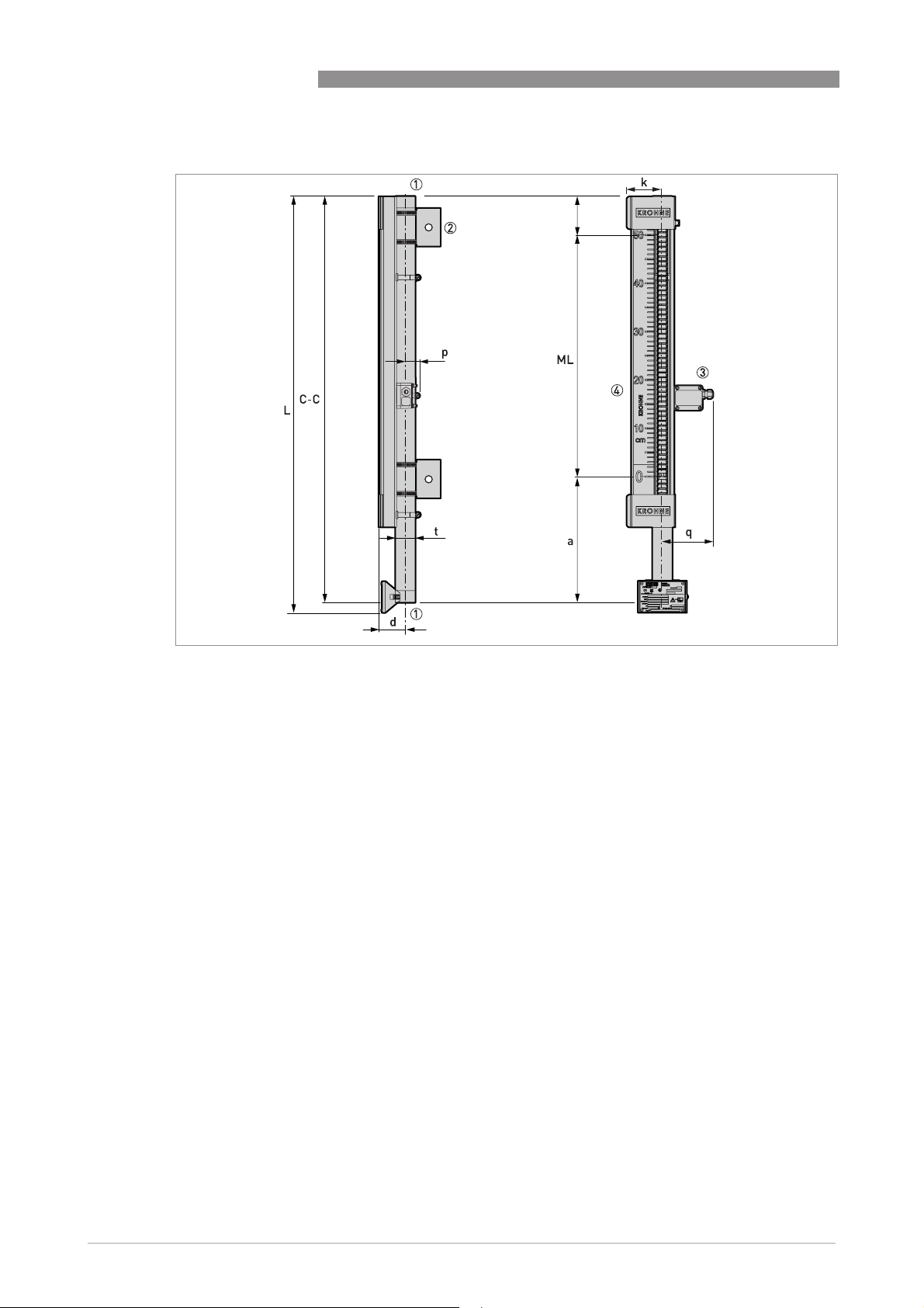
8 TECHNICAL DATA
Basic version: Axial / Axial process connections
BM 26 BASIC/ADVANCED
b
2
Figure 8-3: Axial / Axial process connections
1 3/8 NPT threaded connection
2 Optional support bracket - also refer to "Support bracket option: Dimensions and weight"
3 Optional limit switch
4 Level indicator with optional scale
Note:
Note:
Note: Note:
• C-C = Face-to-face length (process connections)
• ML = Measuring length
• L = Overall length
• a = bottom dead zone; b = top dead zone
60
www.krohne.com 10/2012 - 4000347004 - HB BM26 Basic/Adv R04 en
Page 61

BM 26 BASIC/ADVANCED
Dimensions in mm
TECHNICAL DATA 8
Dimensions [mm]
a b C-C ML d k L p q Øt
Axial / Axial
process connections
274 96 ML
+370
272…
5300
55.5 74 (C-C)
+21
32 113 42.4
Dimensions in inches
Dimensions [inches]
a b C-C ML d k L p q Øt
Axial / Axial
process connections
10.8 3.8 ML
+14.6
10.8…
208
2.5 2.9 (C-C)
+0.8
1.3 4.4 1.7
Weights in kg and lb
Weights Weight for every
additional 100 mm
[kg] [lb] [kg] [lb]
3/8 NPT 6.0 1 13.2 2 0.3 0.7
Limit switch 0.085 0.2
1 When L=500 mm
2 When L=20¨
Weight for every
additional 4 inches
www.krohne.com10/2012 - 4000347004 - HB BM26 Basic/Adv R04 en
61
Page 62

8 TECHNICAL DATA
Basic version: Top lateral / Bottom axial process connections
BM 26 BASIC/ADVANCED
Figure 8-4: Top lateral / Bottom axial process connections
1 3/8 NPT threaded connection
2 Optional drain or vent with 3/8 NPT connection (with plug)
3 Welded cap
4 Flange connection
5 Optional long stud (½¨ or ¾¨) connection
6 Optional male thread (½... ¾ NPT or G ½...¾) connection
7 Optional limit switch
8 Level indicator with optional scale
9 Optional support bracket - also refer to "Support bracket option: Dimensions and weight"
Note:
• C-C = Centre-to-face length (process connections)
• ML = Measuring length
• L = Overall length
• a = bottom dead zone; b = Distance from the axis of the top connection to the top of the device
62
www.krohne.com 10/2012 - 4000347004 - HB BM26 Basic/Adv R04 en
Page 63

BM 26 BASIC/ADVANCED
Dimensions in mm
TECHNICAL DATA 8
Dimensions [mm]
a b C-C ML c d k L p q Øt
Top lateral / Bottom axial
process connections
1 Welded cap option: 149 mm
2 Long stud option: 130 mm. Male thread connection option: 58 mm.
3 Welded cap option: (C-C) +170 mm
300 173 1 ML
+300
370…
5300
135 2 55.5 74 (C-C)
+194
3
32 113 42.4
Dimensions in inches
Dimensions [inches]
a b C-C ML c d k L p q Øt
Top lateral / Bottom axial
process connections
1 Welded cap option: 5.9¨
2 Long stud option: 5.1¨. Male thread connection option: 2.3¨.
3 Welded cap option: (C-C) +6.7¨
11.8 6.8 1 ML
+11.8
14.6…
208
5.3 2 2.2 2.9 (C-C)
+7.6
3
1.3 4.4 1.7
Weights in kg and lb
Weights Weights for every
additional 100 mm
[kg] [lb] [kg] [lb]
Min.: 3/8 NPT / DN15 PN40 flange 6.7 1 14.8 2 0.3 0.7
Max.: 3/8 NPT / 1½¨ 300 lb flange 8.6 1 19.0 2 0.3 0.7
Limit switch 0.085 0.2
1 When L=500 mm
2 When L=20¨
Weights for every
additional 4 inches
www.krohne.com10/2012 - 4000347004 - HB BM26 Basic/Adv R04 en
63
Page 64

8 TECHNICAL DATA
Basic version: Top axial / Bottom lateral process connections
BM 26 BASIC/ADVANCED
Figure 8-5: Top axial / Bottom lateral process connections
1 Optional drain with 3/8 NPT or 1¼ NPT connection (with plug - 1¼ NPT connection is for removal of the float from the
bottom of the device)
2 3/8 NPT threaded connection
3 Flange connection
4 Optional long stud (½¨ or ¾¨) connection
5 Optional male thread (½... ¾ NPT or G ½...¾) connection
6 Optional limit switch
7 Level indicator with optional scale
8 Optional support bracket - also refer to "Support bracket option: Dimensions and weight"
Note:
• C-C = Face-to-centre length (process connections)
• ML = Measuring length
• L = Overall length
• a = Distance from the axis of the bottom connection to the bottom of the device;
b = top dead zone
64
www.krohne.com 10/2012 - 4000347004 - HB BM26 Basic/Adv R04 en
Page 65

BM 26 BASIC/ADVANCED
Dimensions in mm
TECHNICAL DATA 8
Dimensions [mm]
a b C-C ML c d k L p q Øt
Top axial / Bottom lateral
process connections
1 Optional drain with 1¼¨ plug: 323 mm
2 Long stud option: 130.2 mm. Male thread connection option: 58.2 mm.
3 1¼¨ plug option: (C-C) +327 mm
310 1 140 ML
+140
288…
5300
135.2255.5 74 (C-C)
+310
3
32 113 42.4
Dimensions in inches
Dimensions [inches]
a b C-C ML c d k L p q Øt
Top axial / Bottom lateral
process connections
1 Optional drain with 1¼¨ plug: 12.7¨
2 Long stud option: 5.1¨. Male thread connection option: 2.3¨.
3 1¼¨ plug option: (C-C) +12.9¨
12.2 1 5.5 ML
+5.5
11.3…
208
5.3
2
2.2 2.9 (C-C)
+12.2
1.3 4.4 1.7
3
Weights in kg and lb
Weights Weights for every
additional 100 mm
[kg] [lb] [kg] [lb]
Min.: 3/8 NPT / DN15 PN40 flange 6.7 1 14.8 2 0.3 0.7
Max.: 3/8 NPT / 1½¨ 300 lb flange 8.6 1 19.0 2 0.3 0.7
Limit switch 0.085 0.2
1 When L=500 mm
2 When L=20¨
Weights for every
additional 4 inches
www.krohne.com10/2012 - 4000347004 - HB BM26 Basic/Adv R04 en
65
Page 66

8 TECHNICAL DATA
8.6 Advanced version: Dimensions and weights
Advanced version: Lateral / Lateral process connections
BM 26 BASIC/ADVANCED
a
Figure 8-6: Lateral / Lateral process connections
1 Optional vent with 3/8 NPT connection (with plug) , or optional vent with 1/2 NPT, G 1/2 or G 3/8 connection (with plug)
on a plate flange, or drain with 1/2 NPT, 3/8 NPT, G 1/2 or G 3/8 connection (with plug) on a plate flange
2 Process connection (flange)
3 Welded antenna option for the OPTIWAVE 7300 radar level transmitter with ¼ NPT connection for a flushing system
4 ½ BSP connection for OPTIFLEX 1300 TDR level transmitter with ½ NPT lateral vent (with plug)
5 Optional vent and drain (flange)
6 Optional DN40 top flange for other level transmitters
7 Optional limit switch
8 Level indicator with optional scale
9 Optional male thread (½... ¾ NPT or G ½...¾) or long stud (½¨ or ¾¨) connection
Note:
• C-C = Centre-to-centre length (process connections)
• ML = Measuring length
• L = Overall length
• a = Distance from the axis of the bottom connection to the bottom of the device;
b = Distance from the axis of the top connection to the top of the device
66
www.krohne.com 10/2012 - 4000347004 - HB BM26 Basic/Adv R04 en
Page 67

BM 26 BASIC/ADVANCED
Dimensions in mm
TECHNICAL DATA 8
Liquid density
Dimensions [mm]
[kg/l]
a b C-C ML c d e g k L p q r s Øt
Lateral /
Lateral
process
connections
1 For more data, refer to "Floats" at the end of this chapter
2 Optional 1/2NPT or 3/8NPT drain + plug: 480 mm. Optional G1/2 or G3/8 drain + plug: 472 mm. Optional drain flange: 580 mm.
3 Optional 3/8NPT vent: 228 mm. Optional 1/2NPT vent: 228 mm. Optional G1/2 vent: 220 mm. Optional welded OPTIWAVE 7300 trans-
mitter: 542 mm. Optional OPTIFLEX 1300 transmitter with 2 mm single cable probe: 454 mm. Optional flange vent: 328 mm. Optional
DN40 flange: 193 mm.
4 This is equal to the dimension C-C
5 EN flange, type B: 135 mm. EN flange, type C: 135 mm. EN flange, type E: 135 mm. Long stud: 130 mm. Male thread connection: 58 mm.
6 If ambient temperature is -40...-20°C: 85.5 mm (with Plexiglas® cover)
7 Depends on the options selected. Contact your local sales office for more data.
8 Optional 1/2NPT or 3/8NPT drain + plug: 299 mm. Optional G1/2 or G3/8 drain + plug: 291 mm. Optional drain flange: 399 mm.
9 Optional 1/2NPT or 3/8NPT drain + plug: 255 mm. Optional G1/2 or G3/8 drain + plug: 247 mm. Optional drain flange: 355 mm.
0.58…0.7 1
0.7…0.99 1
0.99…2.0 1
2 3 4
8 3 4 5
9 3 4 5
300…
5300
5
55.5 6 106 15 74
55.5 6 106 15 74
55.5 6 106 15 74
7
32 113 259 70 42.4
7
32 113 259 70 42.4
7
32 113 259 70 42.4
Dimensions in inches
Liquid density
[lb/ft³]
a b C-C ML c d e g k L p q r s Øt
Lateral /
Lateral
process
connections
1 For more data, refer to "Floats" at the end of this chapter
2 Optional 1/2NPT or 3/8NPT drain + plug: 18.9¨. Optional G1/2 or G3/8 drain + plug: 18.6¨. Optional drain flange: 22.8¨.
3 Optional 3/8NPT vent: 9.0¨. Optional 1/2NPT vent: 9.0¨. Optional G1/2 vent: 8.6¨. Optional welded OPTIWAVE 7300 transmitter: 21.3¨. Op-
tional OPTIFLEX 1300 transmitter with 0.08¨ single cable probe: 17.9¨. Optional flange vent: 12.9¨. Optional DN40 flange: 7.6¨.
4 This is equal to the dimension C-C
5 EN flange, type B: 5.3¨. EN flange, type C: 5.1¨. EN flange, type E: 5.3¨. Long stud: 5.1¨. Male thread connection: 2.3¨.
6 If ambient temperature is -40...-4°F: 3.4¨ (with Plexiglas® cover)
7 Depends on the options selected. Contact your local sales office for more data.
8 Optional 1/2NPT or 3/8NPT drain + plug: 11.8¨. Optional G1/2 or G3/8 drain + plug: 11.4¨. Optional drain flange: 15.7¨.
9 Optional 1/2NPT or 3/8NPT drain + plug: 10¨. Optional G1/2 or G3/8 drain + plug: 9.7¨. Optional drain flange: 14.0¨.
36.2…43.7 1
43.7…61.8 1
61.8…124.8 1
2 3 4
8 3 4 5
9 3 4 5
12…
5
208
Dimensions [inches]
2.2 6 4.2 0.6 2.9
2.2 6 4.2 0.6 2.9
2.2 6 4.2 0.6 2.9
7
1.3 4.4 10.2 2.8 1.7
7
1.3 4.4 10.2 2.8 1.7
7
1.3 4.4 10.2 2.8 1.7
Weights in kg and lb
Weights Weights for every
additional 100 mm
[kg] [lb] [kg] [lb]
Min.: DN15 PN40 flanges 7.4…8 1 16.3…17.6 2 0.3 0.7
Max: 1½¨ 600 lb flanges 12.4…13 1 27.3…28.7 2 0.3 0.7
Limit switch 0.085 0.2
1 When L=500 mm - if liquid density is low, then weight is higher
2 When L=20¨ - if liquid density is low, then weight is higher
www.krohne.com10/2012 - 4000347004 - HB BM26 Basic/Adv R04 en
Weights for every
additional 4 inches
67
Page 68

8 TECHNICAL DATA
Advanced version: Axial / Axial process connections
BM 26 BASIC/ADVANCED
t
Figure 8-7: Axial / Axial process connections
1 Process connection (flange)
2 Optional limit switch
3 Level indicator with optional scale
4 Optional support bracket - also refer to "Support bracket option: Dimensions and weight"
Note:
• C-C = Face-to-face length (process connections)
• ML = Measuring length
• L = Overall length
• a = bottom dead zone; b = top dead zone
68
www.krohne.com 10/2012 - 4000347004 - HB BM26 Basic/Adv R04 en
Page 69

BM 26 BASIC/ADVANCED
Dimensions in mm
TECHNICAL DATA 8
Liquid density
[kg/l]
a b C-C ML d e k L p q Øt
Axial / Axial
process
connections
1 For more data, refer to "Floats" at the end of this chapter
2 If ambient temperature is -40...-20°C: 85.5 mm (with Plexiglas® cover)
3 This is equal to the dimension C-C
0.58…0.7 1 570 250 ML +820 300...
0.7…0.99 1 390 250 ML +640 55.5 2 106 74
0.99…2.0 1 340 250 ML +590 55.5 2 106 74
5300
Dimensions in inches
Liquid density
[lb/ft³]
a b C-C ML d e k L p q Øt
Axial / Axial
process
connections
1 For more data, refer to "Floats" at the end of this chapter
2 If ambient temperature is -40...-4°F: 3.4¨ (with Plexiglas® cover)
3 This is equal to the dimension C-C
36.2…43.7 1 22.4 9.8 ML +32.3 11.8...
43.7…61.8 1 15.3 9.8 ML +25.2 2.2 2 4.2 2.9
61.8…124.8 1 13.4 9.8 ML +23.2 2.2 2 4.2 2.9
Weights in kg and lb
Dimensions [mm]
55.5 2 106 74
Dimensions [inches]
2.2 2 4.2 2.9
208
3
3
3
3
3
3
32 113 42.4
38 113 42.4
32 113 42.4
1.3 4.4 1.7
1.3 4.4 1.7
1.3 4.4 1.7
Weights Weights for every
additional 100 mm
Weights for every
additional 4 inches
[kg] [lb] [kg] [lb]
Min.: DN15 PN40 flanges 7.4…8 1 16.3…17.6 2 0.3 0.7
Max: 1½¨ 600 lb flanges 12.4…13 1 27.3…28.7 2 0.3 0.7
Limit switch 0.085 0.2
1 When L=500 mm - if liquid density is low, then weight is higher
2 When L=20¨ - if liquid density is low, then weight is higher
www.krohne.com10/2012 - 4000347004 - HB BM26 Basic/Adv R04 en
69
Page 70

8 TECHNICAL DATA
Advanced version: Top lateral / Bottom axial process connections
BM 26 BASIC/ADVANCED
b
2
Figure 8-8: Top lateral / Bottom axial process connections
1 Optional vent with 3/8 NPT connection (with plug) or optional vent with 1/2 NPT or G 1/2 connection (with plug) on a
plate flange
2 Process connection (flange)
3 Welded antenna option for the OPTIWAVE 7300 radar level transmitter with ¼ NPT connection for a flushing system
4 ½ BSP connection for OPTIFLEX 1300 TDR level transmitter with ½ NPT lateral vent (with plug)
5 Optional vent (flange)
6 Optional DN40 top flange for other level transmitters with ½ NPT lateral vent (with plug)
7 Optional level switch
8 Level indicator with optional scale
9 Optional male thread (½... ¾ NPT or G ½...¾) or long stud (½¨ or ¾¨) connection
10 Optional support bracket - also refer to "Support bracket option: Dimensions and weight"
Note:
• C-C = Centre-to-face length (process connections)
• ML = Measuring length
• L = Overall length
• a = bottom dead zone; b = Distance from the axis of top connection to the top of the device
70
www.krohne.com 10/2012 - 4000347004 - HB BM26 Basic/Adv R04 en
Page 71

BM 26 BASIC/ADVANCED
Dimensions in mm
TECHNICAL DATA 8
Liquid
Dimensions [mm]
density
[kg/l]
Top lateral /
Bottom axial
process
connections
1 For more data, refer to "Floats" at the end of this chapter
2 Optional 3/8NPT vent: 228mm. Optional 1/2NPT vent: 228 mm. Optional G1/2 vent: 220 mm. Optional welded OPTIWAVE 7300 transmit-
ter: 542 mm. Optional OPTIFLEX 1300 transmitter with 2 mm single cable probe: 454 mm. Optional flange vent: 328 mm. Optional DN40
flange: 193 mm.
3 EN flange, type B: 135.2 mm. EN flange, type C: 134.7 mm. EN flange, type E: 135.2 mm. Long stud: 130.2 mm. Male thread connection:
58.2 mm.
4 If ambient temperature is -40...-20°C: 85.5 mm (with Plexiglas® cover)
5 Depends on the options selected. Contact your local sales office for more data.
0.58…
1
0.7
0.7…
0.99
1
0.99…
2.0
1
a b C-C ML c d e g k L p q r s Øt
580
400
360
2
ML
300
+580
ML
300
2
+400
2
ML
+360
...5
3
55.54106 15 74
3
55.54106 15 74
3
55.54106 15 74
5
32 113 259 70 42.4
5
32 113 259 70 42.4
5
32 113 259 70 42.4
Dimensions in inches
Liquid
density
[lb/ft³]
Top lateral /
Bottom axial
process
connections
1 For more data, refer to "Floats" at the end of this chapter
2 Optional 3/8NPT vent: 9.0¨. Optional 1/2NPT vent: 9.0¨. Optional G1/2 vent: 8.6¨. Optional welded OPTIWAVE 7300 transmitter: 21.3¨. Op-
tional OPTIFLEX 1300 transmitter with 0.08¨ single cable probe: 17.9¨. Optional flange vent: 12.9¨. Optional DN40 flange: 7.6¨.
3 EN flange, type B: 5.3¨. EN flange, type C: 5.1¨. EN flange, type E: 5.3¨. Long stud: 5.1¨. Male thread connection: 2.3¨.
4 If ambient temperature is -40...-4°F: 3.4¨ (with Plexiglas® cover)
5 Depends on the options selected. Contact your local sales office for more data.
36.2…
43.7
1
43.7…
61.8
1
61.8…
124.8
a b C-C ML c d e g k L p q r s Øt
1
22.8
15.7
14.2
2
ML
+22.8
ML
208
2
+15.7
2
ML
+14.2
11.
8...
3
3
3
Dimensions [inches]
2.244.2 0.6 2.9
2.244.2 0.6 2.9
2.244.2 0.6 2.9
5
1.3 4.4 10.2 2.8 1.7
5
1.3 4.4 10.2 2.8 1.7
5
1.3 4.4 10.2 2.8 1.7
Weights in kg and lb
Weights Weights for every
additional 100 mm
[kg] [lb] [kg] [lb]
Min.: DN15 PN40 flanges 6.7…7.3 1 14.8…16.1 2 0.3 0.7
Max: 1½¨ 600 lb flanges 9.2…9.8 1 20.3…21.6 2 0.3 0.7
Limit switch 0.085 0.2
1 When L=500 mm - if liquid density is low, then weight is higher
2 When L=20¨ - if liquid density is low, then weight is higher
www.krohne.com10/2012 - 4000347004 - HB BM26 Basic/Adv R04 en
Weights for every
additional 4 inches
71
Page 72

8 TECHNICAL DATA
Advanced version: Top axial / Bottom lateral process connections
BM 26 BASIC/ADVANCED
Figure 8-9: Top axial / Bottom lateral process connections
1 Process connection (flange)
2 Optional male thread (½... ¾ NPT or G ½...¾) or long stud (½¨ or ¾¨) connection
3 Optional level switch
4 Level indicator with optional scale
5 Optional drain (flange)
6 Optional drain with 1/2 NPT, 3/8 NPT, G 1/2 or G 3/8 connection (with plug) on a plate flange
7 Optional support bracket - also refer to "Support bracket option: Dimensions and weight"
Note:
• C-C = Face-to-centre length (process connections)
• ML = Measuring length
• L = Overall length
• a = Distance from the axis of the bottom connection to the bottom of the device;
b = top dead zone
72
www.krohne.com 10/2012 - 4000347004 - HB BM26 Basic/Adv R04 en
Page 73

BM 26 BASIC/ADVANCED
Dimensions in mm
TECHNICAL DATA 8
Liquid
Dimensions [mm]
density
[kg/l]
Top axial /
Bottom lateral
process
connections
1 For more data, refer to "Floats" at the end of this chapter
2 Optional 1/2NPT or 3/8NPT drain + plug: 480 mm. Optional G1/2 or G3/8 drain + plug: 472 mm. Optional drain flange: 580 mm.
3 EN flange, type B: 135.2 mm. EN flange, type C: 134.7 mm. EN flange, type E: 135.2 mm. Long stud: 130.2 mm. Male thread connection:
58.2 mm.
4 If ambient temperature is -40...-20°C: 85.5 mm (with Plexiglas® cover)
5 Depends on the options selected. Contact your local sales office for more data.
6 Optional 1/2NPT or 3/8NPT drain + plug: 299 mm. Optional G1/2 or G3/8 drain + plug: 291 mm. Optional drain flange: 399 mm.
7 Optional 1/2NPT or 3/8NPT drain + plug: 255 mm. Optional G1/2 or G3/8 drain + plug: 247 mm. Optional drain flange: 355 mm.
0.58…
1
0.7
0.7…
0.99
1
0.99…
2.0
1
a b C-C ML c d k L p q Øt
2
330 ML +330 300...
6
310 ML +310
7
320 ML +320
5300
3
55.5
4
3
55.5
4
3
55.5
4
74
74
74
5
5
5
32 113 42.4
32 113 42.4
32 113 42.4
Dimensions in inches
Liquid
density
[lb/ft³]
Top axial /
Bottom lateral
process
connections
1 For more data, refer to "Floats" at the end of this chapter
2 Optional 1/2NPT or 3/8NPT drain + plug: 18.9¨. Optional G1/2 or G3/8 drain + plug: 18.6¨. Optional drain flange: 22.8¨.
3 EN flange, type B: 5.3¨. EN flange, type C (tongue): 5.1¨. EN flange, type E: 5.3¨. Long stud: 5.1¨. Male thread connection: 2.3¨.
4 If ambient temperature is -40...-4°F: 3.4¨ (with Plexiglas® cover)
5 Depends on the options selected. Contact your local sales office for more data.
6 Optional 1/2NPT or 3/8NPT drain + plug: 11.8¨. Optional G1/2 or G3/8 drain + plug: 11.4¨. Optional drain flange: 15.7¨.
7 Optional 1/2NPT or 3/8NPT drain + plug: 10¨. Optional G1/2 or G3/8 drain + plug: 9.7¨. Optional drain flange: 14.0¨.
36.2…
43.7
1
43.7…
61.8
1
61.8…
124.8
1
a b C-C ML c d k L p q Øt
2
6
7
13 ML +13 11.8...
12.2 ML +12.2
12.6 ML +12.6
Dimensions [inches]
3
2.2
208
3
2.2
3
2.2
2.9
4
2.9
4
2.9
4
5
1.3 4.4 1.7
5
1.3 4.4 1.7
5
1.3 4.4 1.7
Weights in kg and lb
Weights Weights for every
additional 100 mm
[kg] [lb] [kg] [lb]
Min.: DN15 PN40 flanges 6.7…7.3 1 14.8…16.1 2 0.3 0.7
Max: 1½¨ 600 lb flanges 9.2…9.8 1 20.3…21.6 2 0.3 0.7
Limit switch 0.085 0.2
1 When L=500 mm - if liquid density is low, then weight is higher
2 When L=20¨ - if liquid density is low, then weight is higher
www.krohne.com10/2012 - 4000347004 - HB BM26 Basic/Adv R04 en
Weights for every
additional 4 inches
73
Page 74

8 TECHNICAL DATA
8.7 Analog transmitter: Dimensions and weight
BM 26 BASIC/ADVANCED
Figure 8-10: Analog transmitter
1 Non-Ex or Ex i analog transmitter (at the top of the reed chain)
2 Non-Ex or Ex i analog transmitter (at the bottom of the reed chain)
3 Non-Ex or Ex i analog transmitter (at the top of the reed chain, with optional LCD indicator)
4 Non-Ex or Ex i analog transmitter (at the bottom of the reed chain, with optional LCD indicator)
Dimensions in mm
Converter Dimensions [mm]
a b c ML d e
Non-Ex or Ex i 52 103 189
Non-Ex or Ex i, with optional LCD indicator 52 115 234
1 Refer to the dimension ML for each device version
Dimensions in inches
Converter Dimensions [inches]
a b c ML d e
Non-Ex or Ex i 2.1 4.1 7.4
Non-Ex or Ex i, with optional LCD indicator 2.1 4.5 9.2
1 Refer to the dimension ML for each device version
1
1
1
1
83 50
90 50
3.3 2.0
3.5 2.0
Weights in kg and lb
Converter Weights for 1mWeights for
40 inches
[kg] [lb] [kg] [lb]
Non-Ex or Ex i 1.32 2.9 +1 +2.20
Non-Ex or Ex i, with optional LCD indicator 1.85 4.1 +1 +2.20
74
www.krohne.com 10/2012 - 4000347004 - HB BM26 Basic/Adv R04 en
Weights for every
additional 1000 mm
Weights for every
additional 40 inches
Page 75

BM 26 BASIC/ADVANCED
8.8 Support bracket option: Dimensions and weight
TECHNICAL DATA 8
Figure 8-11: Support bracket option
1 Attach the collar to the measuring chamber
2 Attach the plate to the tank
Dimensions and weights in mm and kg
Dimensions [mm] Weights
[kg]
a b c d e f
Support bracket 50 25 80 40 5 Ø15 0.22
Dimensions and weights in inches and lb
Dimensions [inches] Weights
a b c d e f
Support collar 2 1 3.14 1.57 0.2 Ø0.6 0.48
[lb]
www.krohne.com10/2012 - 4000347004 - HB BM26 Basic/Adv R04 en
75
Page 76

8 TECHNICAL DATA
8.9 Guidelines for maximum operating pressure
Make sure that the devices are used within their operating limits. Observe the following
requirements:
Pressure derating chart for the Basic version in barg
BM 26 BASIC/ADVANCED
1 Process pressure, P [barg]
2 Length of the indicator, L [m]
Pressure derating chart for the Basic version in psig
1 Process pressure, P [psig]
2 Length of the indicator, L [ft]
INFORMATION!
The EU Pressure Equipment Directive does not apply to the use of the BM 26 Basic.
76
www.krohne.com 10/2012 - 4000347004 - HB BM26 Basic/Adv R04 en
Page 77

BM 26 BASIC/ADVANCED
Pressure derating chart (PED 97/23/EC) for the Advanced version with a 316 L
measuring chamber in barg
1 Process pressure, P [barg]
2 Process temperature, T [°C]
3 PN40, PN63, PN100 (EN 1092-1), 300LB (ASME B16.5) flanges, welded pipes and threaded pipes
4 150LB (ASME B16.5) flanges
TECHNICAL DATA 8
Pressure derating chart (PED 97/23/EC) for the Advanced version with a 316 L
measuring chamber in psig
1 Process pressure, P [psig]
2 Process temperature, T [°F]
3 PN40, PN63, PN100 (EN 1092-1), 300LB (ASME B16.5) flanges, welded pipes and threaded pipes
4 150LB (ASME B16.5) flanges
www.krohne.com10/2012 - 4000347004 - HB BM26 Basic/Adv R04 en
77
Page 78

8 TECHNICAL DATA
8.10 Floats
Make sure that the devices are used within the operating limits of the floats. Refer to the table
and graphs that follow:
BM 26 Basic: Application limits of floats in °C, bar and kg/l
BM 26 BASIC/ADVANCED
Dimensions Material Density
Maximum operating pressure [barg]
range
[mm] [kg/l] 20°C 100°C 150°C
Float Ø32 × 245 316L 0.80…1.19 16 15.1 13.7
BM 26 Basic: Application limits of floats in °F, psi and lb/ft³
Dimensions Material Density
range
[inches] [lb/ft³] 70°F 210°F 300°F
Float Ø1.3 × 9.6 316L 49.9…74.3 232 219 199
Maximum operating pressure [psig]
BM 26 Advanced: Application limits of floats in °C, bar and kg/l
Dimensions Material Density
range
[mm] [kg/l] 20°C 100°C 150°C 200°C 250°C 300°C
Float 1 Ø32 × 420 Titanium 0.58…0.7 40 37.9 34.4 31.8 29.8 27.6
Float 2 Ø32 × 240 Titanium 0.7…0.99 40 37.9 34.4 31.8 29.8 27.6
Float 3 Ø32 × 185 316L 1 0.99…2.0 40 37.9 34.4 31.8 29.8 27.6
1 Hastelloy® C-276 is available on request
Maximum operating pressure [barg]
BM 26 Advanced: Application limits of floats in °F, psi and lb/ft³
Dimensions Material Density
range
[inches] [lb/ft³] 70°F 210°F 300°F 390°F 480°F 570°F
Float 1 Ø1.3 × 16.5 Titanium 36.2…43.7 580 449 500 461 432 400
Float 2 Ø1.3 × 9.4 Titanium 43.7…61.8 580 449 500 461 432 400
Float 3 Ø1.3 × 7.3 316L 1 61.8…124.8 580 449 500 461 432 400
1 Hastelloy® C-276 is available on request
78
www.krohne.com 10/2012 - 4000347004 - HB BM26 Basic/Adv R04 en
Maximum operating pressure [psig]
Page 79

BM 26 BASIC/ADVANCED
9.1 Liquid level offset: description
The float contains magnets that rotate the flaps in the indicator column on the side of the
measuring chamber. The position of the magnets does not correspond to the level of liquid so
the scale is offset at the factory to take into account this difference. The offset of the magnets
depends on the liquid density. Refer to the illustration that follows:
Magnet offset
APPENDIX 9
Figure 9-1: Magnet offset
1 True level of the liquid
2 Top of the float magnet (which corresponds to the level shown on the indicator column)
3 Difference (offset) between the true level of the liquid and the top of the float magnet (depends on the liquid density)
4 Indicator column of yellow/black rotating flaps (with the optional scale)
CAUTION!
If the product density changes, the device will not measure accurately. Contact your local sales
office for more data and advice.
INFORMATION!
The limit switches are not delivered attached to the device and the liquid level offset must be
taken into account. For the limit switch installation procedure, refer to Optional limit switch on
page 23
. For liquid level offset switches and other correction data, refer to
correction data on page 80
.
Liquid level offset:
www.krohne.com10/2012 - 4000347004 - HB BM26 Basic/Adv R04 en
79
Page 80

9 APPENDIX
9.2 Liquid level offset: correction data
Liquid level offset
Figure 9-2: Liquid level offset
1 Top of the magnets
2 Maximum liquid level
3 Minimum liquid level
h is the length of the float,
a is the distance to the zero point of the magnets from the top of the float
d is the liquid level relative to the zero point of the magnet
BM 26 BASIC/ADVANCED
Dimensions in mm and kg/l
Float Product density Dimensions [mm]
[kg/l] a h d
Basic version, float 1 0.8…1.19 45 245
Advanced version, float 1 0.58…0.7 45 420
Advanced version, float 2 0.7…0.99 45 240
Advanced version, float 3 0.99…2.0 45 185
1 Refer to the graphs that follow
Dimensions in inches and lb/ft³
Float Product density Dimensions [inches]
[lb/ft³] a h d
Basic version, float 1 49.9…74.3 1.8 9.6
Advanced version, float 1 36.2…43.7 1.8 16.5
Advanced version, float 2 43.7…61.8 1.8 9.4
Advanced version, float 3 61.8…124.8 1.8 7.3
1 Refer to the graphs that follow
1
1
1
1
1
1
1
1
80
www.krohne.com 10/2012 - 4000347004 - HB BM26 Basic/Adv R04 en
Page 81

BM 26 BASIC/ADVANCED
Basic version: Float magnet offset in relation to liquid level in mm
Figure 9-3: Basic version: Float magnet offset in relation to liquid level in mm
1 Liquid level in relation to the magnet zero point, d [mm]
2 Liquid density, ρ [g/cm³]
3 Curve for Basic version float
APPENDIX 9
Basic version: Float magnet offset in relation to liquid level in inches
Figure 9-4: Basic version: Float magnet offset in relation to liquid level in inches
1 Liquid level in relation to the magnet zero point, d [inches]
2 Liquid density, ρ [lb/ft³]
3 Curve for Basic version float
www.krohne.com10/2012 - 4000347004 - HB BM26 Basic/Adv R04 en
81
Page 82

9 APPENDIX
Advanced version: Float magnet offset in relation to liquid level in mm
Figure 9-5: Advanced version: Float magnet offset in relation to liquid level in mm
1 Liquid level in relation to the magnet zero point, d [mm]
2 Liquid density, ρ [g/cm³]
3 Curve for Advanced version float 1
4 Curve for Advanced version float 2
5 Curve for Advanced version float 3
BM 26 BASIC/ADVANCED
Advanced version: Float magnet offset in relation to liquid level in inches
Figure 9-6: Advanced version: Float magnet offset in relation to liquid level in inches
1 Liquid level in relation to the magnet zero point, d [inches]
2 Liquid density, ρ [lb/ft³]
3 Curve for Advanced version float 1
4 Curve for Advanced version float 2
5 Curve for Advanced version float 3
82
www.krohne.com 10/2012 - 4000347004 - HB BM26 Basic/Adv R04 en
Page 83

BM 26 BASIC/ADVANCED
9.3 Glossary
A
Analog transmitter
Analog transmitter An optional device that transmits an output given by the position of a
Analog transmitterAnalog transmitter
E
Electromagnetic compatibility
Electromagnetic compatibility Defines how much a device influences or is influenced by other devices that
Electromagnetic compatibilityElectromagnetic compatibility
F
Float
Float An air-filled, sealed cylinder that contains magnets. The float stays on the
FloatFloat
APPENDIX 9
magnetic field along a resistance reed chain. The resistance reed chain is
in a tube attached adjacent to the measuring chamber. Output options
include 4...20 mA, HART, PROFIBUS PA and FOUNDATION™ Fieldbus.
generate electromagnetic fields during operation. Refer to European
standard EN 61326-1 and EN 61326-2-3 for further details.
surface of liquid in the measuring chamber. The magnetic field of the float
operates equipment adjacent to the measuring chamber: this includes the
level indicator column, the optional analog transmitter and optional limit
switches.
L
Level indicator
Level indicator The level indicator is column of 2-color, rotating flaps (or a floating index, if
Level indicatorLevel indicator
Limit switch
Limit switch An optional device with a reed contact that is operated by the magnetic field
Limit switchLimit switch
this option is available) sealed in a heat-resistant glass tube. An optional
scale show the level in the tank in m + cm, feet + inches or % filled.
of the float. It is attached at one or more points adjacent to the measuring
chamber. It indicates when the level of the liquid is at a reference point.
The switch is bi-stable. The switch stays "open" or "closed" until the float
goes back to its initial position.
M
Measuring chamber
Measuring chamber The measuring chamber is a bypass chamber that is attached adjacent to a
Measuring chamberMeasuring chamber
tank with contents that must be measured. There are 2 process
connections: 1 at the top and 1 at the bottom of the measuring chamber.
The measuring chamber contains a float. Options include axial or lateral
process connections, vents, drains and support collars
R
Radar level transmitter
Radar level transmitter An optional device that transmits a high frequency signal whose frequency
Radar level transmitterRadar level transmitter
increases linearly during the measurement phase (called the frequency
sweep). The signal is emitted, reflected on the measuring surface and
received with a time delay. The frequency difference is processed and the
result is the distance to the surface of the liquid. This data is converted into
an output. For more data, refer to technical documentation for the
OPTIWAVE 7300 C.
www.krohne.com10/2012 - 4000347004 - HB BM26 Basic/Adv R04 en
83
Page 84

9 APPENDIX
T
TDR
TDR Time domain reflectometry (TDR). The principle used by the TDR level
TDRTDR
TDR level transmitter
TDR level transmitter An optional device (attached to the top of the measuring chamber) that
TDR level transmitterTDR level transmitter
9.4 Order code
The characters of the order code highlighted in light grey describe the standard.
Basic version
BM 26 BASIC/ADVANCED
transmitter. For more data, refer to technical documentation for the
OPTIFLEX 1300 C.
transmits low-intensity electromagnetic pulses along a rigid or flexible
conductor. When the pulses get to the surface of the product to be
measured, the pulses are reflected. The device measures the time from
when the pulse is transmitted to when it is received: half of this time is
equivalent to the distance from the reference point of the device (the thread
stop) to the surface of the product. The time value is converted into an
output. For more data, refer to technical documentation for the
OPTIFLEX 1300 C.
VF41 4 BM 26 Basic Magnetic bypass level indicator:
VF41
VF41 4 Order code (complete this code on the pages that follow)
VF41VF41
BM 26 Basic Magnetic bypass level indicator:
BM 26 Basic Magnetic bypass level indicator:BM 26 Basic Magnetic bypass level indicator:
-40...+150
-40...+150°C and -16 bar max. / -40...300
-40...+150-40...+150
Material
Material
MaterialMaterial
0 316L
C and -16 bar max. / -40...300°F and 232 psi max.
C and -16 bar max. / -40...300C and -16 bar max. / -40...300
Approval
Approval
ApprovalApproval
0 Non-Ex
1 ATEX
Other approval
Other approval
Other approvalOther approval
0 Without
Process temperature
Process temperature
Process temperatureProcess temperature
1 -40...+150°C (-40...+300°F)
Density [kg/l]/Float material
Density [kg/l]/Float material
Density [kg/l]/Float materialDensity [kg/l]/Float material
1 0.8...1.19 / 316L
Orientation of process connections
Orientation of process connections
Orientation of process connectionsOrientation of process connections
0 Lateral / Lateral
1 Bottom lateral / Top axial
2 Bottom axial / Top lateral
3 Axial / Axial
4 Bottom lateral / Top axial + 1 support bracket
5 Bottom axial / Top lateral + 1 support bracket
6 Axial / Axial + 2 support brackets
Process connection type
Process connection type
Process connection typeProcess connection type
0 Without (3/8 NPTF for axial process connections)
1 Flange connection
2 Welded connection
3 Threaded connection (male)
Order code (complete this code on the pages that follow)
Order code (complete this code on the pages that follow)Order code (complete this code on the pages that follow)
F and 232 psi max.
F and 232 psi max.F and 232 psi max.
84
www.krohne.com 10/2012 - 4000347004 - HB BM26 Basic/Adv R04 en
Page 85

BM 26 BASIC/ADVANCED
Process connection
Process connection
Process connectionProcess connection
0 Without
1 DN15 PN40
3 DN20 PN40
5 DN25 PN40
7 DN40 PN40
D ½¨ 150LB
E ½¨ 300LB
F ¾¨ 150LB
G ¾¨ 300LB
H 1¨ 150LB
K 1¨ 300LB
L 1½¨ 150LB
M 1½¨ 300LB
R Welded pipe ½¨, sch10, length 107 mm
S Welded pipe ¾¨, sch10, length 107 mm
T Threaded pipe ¾ NPT, Sch10, male, length 35 mm
U Threaded pipe ½ NPT, Sch10, male, length 35 mm
V Threaded pipe G ¾, Sch10, male, length 35 mm
W Threaded pipe G ½, Sch10, male, length 35 mm
Flange facing
Flange facing
Flange facingFlange facing
0 Without (options without flange connections)
B Form B1 (EN 1092-1)
F Form RF (ASME B16.5)
Vent
Vent
VentVent
0 Without
1 3/8 NPT + plug
Drain
Drain
DrainDrain
1 3/8 NPT + plug
2 1¼ NPT + plug (without flange)
Sealing
Sealing
SealingSealing
0 Without
Indicator / scale
Indicator / scale
Indicator / scaleIndicator / scale
0 Without indication
1 Flaps / without scale
2 Flaps / m + cm
3 Flaps / feet + inch
4 Flaps / %
VF41
VF41 4 Order code (complete this code on the pages that follow)
VF41VF41
Order code (complete this code on the pages that follow)
Order code (complete this code on the pages that follow)Order code (complete this code on the pages that follow)
APPENDIX 9
www.krohne.com10/2012 - 4000347004 - HB BM26 Basic/Adv R04 en
85
Page 86

9 APPENDIX
Transmitter/Converter position
Transmitter/Converter position
Transmitter/Converter positionTransmitter/Converter position
0 Without
D LT40 (4-20 mA) + display / top of chamber
E LT40 (4-20 mA+HART) + display / top of chamber 1
F LT40 (4-20 mA) / top of chamber
G LT40 (4-20 mA+HART) / top of chamber
H LT40 (FF) / top of chamber
K LT40 (PROFIBUS PA) / top of chamber
N LT40 (4-20 mA) + display / bottom of chamber
P LT40 (4-20 mA+HART) + display / bottom of chamber 1
R LT40 (4-20 mA) / bottom of chamber
S LT40 (4-20 mA+HART) / bottom of chamber
T LT40 (FF) / bottom of chamber
U LT40 (PROFIBUS PA) / bottom of chamber
Transmitter approval
Transmitter approval
Transmitter approvalTransmitter approval
0 Without
1 Ex i
Number of limit switches
Number of limit switches
Number of limit switchesNumber of limit switches
0 Without
1 1 switch
2 2 switches
3 3 switches
4 4 switches
5 5 switches
Limit switch approval
Limit switch approval
Limit switch approvalLimit switch approval
0 Without
1 Ex i
A Namur (DIN 19234)
B Namur (DIN 19234), Ex i
VF41
VF41 4 0 0
VF41VF41
Certificate for calibration
Certificate for calibration
Certificate for calibrationCertificate for calibration
0 Without
1 Adjustment certificate
VF41
VF41 4 0 0 0
VF41VF41
VF41
VF41 4 0 0 0 Order code (complete this
VF41VF41
BM 26 BASIC/ADVANCED
Tag number
Tag number
Tag numberTag number
0 Without
2 Tag n° on nameplate
Order code (complete this
Order code (complete this Order code (complete this
code on the pages that follow)
code on the pages that follow)
code on the pages that follow)code on the pages that follow)
86
www.krohne.com 10/2012 - 4000347004 - HB BM26 Basic/Adv R04 en
Page 87

BM 26 BASIC/ADVANCED
VF41
VF41 4 0 0 0 Order code
VF41VF41
1 For non-Ex devices only
APPENDIX 9
C-C length
C-C length
C-C lengthC-C length
0 0m
1 1m
2 2m
3 3m
4 4m
5 5 m (5.3 m max.)
C-C length
C-C length
C-C lengthC-C length
0 0mm
1 100 mm
2 200 mm
3 300 mm
4 400 mm
5 500 mm
6 600 mm
7 700 mm
8 800 mm
A 900 mm
Order code
Order codeOrder code
www.krohne.com10/2012 - 4000347004 - HB BM26 Basic/Adv R04 en
87
Page 88

9 APPENDIX
Advanced version
BM 26 BASIC/ADVANCED
VF42 4 BM 26 Advanced Magnetic bypass level indicator:
VF42
VF42 4 Order code (complete this code on the pages that follow)
VF42VF42
BM 26 Advanced Magnetic bypass level indicator:
BM 26 Advanced Magnetic bypass level indicator:BM 26 Advanced Magnetic bypass level indicator:
40 bar max. at 20
40 bar max. at 20°C / 27.6 bar max. at 300
40 bar max. at 2040 bar max. at 20
Material
Material
MaterialMaterial
0 316L
1
Hastelloy® C-276 (on request)
Approval
Approval
ApprovalApproval
0 Non-Ex
1 ATEX
Other approval
Other approval
Other approvalOther approval
0 Without
C / 27.6 bar max. at 300°C (580 psi max. at 68
C / 27.6 bar max. at 300C / 27.6 bar max. at 300
Process temperature
Process temperature
Process temperatureProcess temperature
0 -40...+20°C (-40...+68°F)
1 -40...+50°C (-40...+122°F)
2 -40...+100°C (-40...+212°F)
3 -40...+150°C (-40...+302°F)
4 -40...+200°C (-40...+392°F)
5 -40...+250°C (-40...+122°F)
6 -40...+300°C (-40...+572°F)
Density [kg/l]/Float material
Density [kg/l]/Float material
Density [kg/l]/Float materialDensity [kg/l]/Float material
0 Without
1 0.58...0.7 / Titanium
2 0.70...0.99 / Titanium
3 0.99...2 / 316L
A
0.99...2 / Hastelloy® (on request)
Orientation of process connections
Orientation of process connections
Orientation of process connectionsOrientation of process connections
0 Lateral / Lateral
1 Bottom lateral / Top axial
2 Bottom axial / Top lateral
3 Axial / Axial
4 Bottom lateral / Top axial + 1 support bracket
5 Bottom axial / Top lateral + 1 support bracket
6 Axial / Axial + 2 support brackets
Process connection type
Process connection type
Process connection typeProcess connection type
0 Without
1 Flange connection
2 Welded connection
3 Threaded connection (male)
4 Loose flange EN
Order code (complete this code on the pages that follow)
Order code (complete this code on the pages that follow)Order code (complete this code on the pages that follow)
C (580 psi max. at 68°F / 400 psi maxi. at 572
C (580 psi max. at 68C (580 psi max. at 68
F / 400 psi maxi. at 572°F)
F / 400 psi maxi. at 572F / 400 psi maxi. at 572
F)
F)F)
88
www.krohne.com 10/2012 - 4000347004 - HB BM26 Basic/Adv R04 en
Page 89

BM 26 BASIC/ADVANCED
Process connection
Process connection
Process connectionProcess connection
0 Without
1 DN15 PN40
2 DN15 PN100
3 DN20 PN40
4 DN20 P100
5 DN25 PN40
6 DN25 PN100
7 DN40 PN40
8 DN40 PN100
A DN50 PN40
B DN50 PN63
C DN50 PN100
D ½¨ 150LB
E ½¨ 300LB
F ¾¨ 150LB
G ¾¨ 300LB
H 1¨ 150LB
K 1¨ 300LB
L 1½¨ 150LB
M 1½¨ 300LB
N 2¨ 150LB
P 2¨ 300LB
R Welded pipe ½¨, sch10, length 107 mm
S Welded pipe ¾¨, sch10, length 107 mm
T Threaded pipe ¾ NPT, Sch10, male, length 35 mm
U Threaded pipe ½ NPT, Sch10, male, length 35 mm
V Threaded pipe G ¾, Sch10, male, length 35 mm
W Threaded pipe G ½, Sch10, male, length 35 mm
Flange facing
Flange facing
Flange facingFlange facing
0 Without (options without flange connections)
B Form B1 (EN 1092-1)
C Form C (EN 1092-1, male)
E Form E (EN 1092-1, male)
F Form RF (ASME B16.5)
Vent
Vent
VentVent
0 Without
1 3/8 NPT + plug
3 ½ NPT
4 DN40 PN40 top flange + lateral vent ½ NPT (with plug)
5 Weld connection for OPTIWAVE 7300 C
6 G ½
A As per process connection
VF42
VF42 4 Order code (complete this code on the pages that follow)
VF42VF42
Order code (complete this code on the pages that follow)
Order code (complete this code on the pages that follow)Order code (complete this code on the pages that follow)
APPENDIX 9
www.krohne.com10/2012 - 4000347004 - HB BM26 Basic/Adv R04 en
89
Page 90

9 APPENDIX
Drain
Drain
DrainDrain
1 Flange + 3/8 NPT
2 Flange + ½ NPT
3 Flange + G 3/8
4 Flange + G ½
A Flange (as per process connection)
Sealing
Sealing
SealingSealing
0 Without
1 Aramid (without asbestos)
2 316L graphite
3 PTFE
Indicator / scale
Indicator / scale
Indicator / scaleIndicator / scale
0 Without indication
1 Flaps / without scale
2 Flaps / m + cm
3 Flaps / feet + inch
4 Flaps / %
Transmitter/Converter position
Transmitter/Converter position
Transmitter/Converter positionTransmitter/Converter position
0 Without
D LT40 (4-20 mA) + display / top of chamber
E LT40 (4-20 mA+HART) + display / top of chamber 1
F LT40 (4-20 mA) / top of chamber
G LT40 (4-20 mA+HART) / top of chamber
H LT40 (FF) / top of chamber
K LT40 (PROFIBUS PA) / top of chamber
N LT40 (4-20 mA) + display / bottom of chamber
P LT40 (4-20 mA+HART) + display / bottom of chamber 1
R LT40 (4-20 mA) / bottom of chamber
S LT40 (4-20 mA+HART) / bottom of chamber
T LT40 (FF) / bottom of chamber
U LT40 (PROFIBUS PA) / bottom of chamber
Transmitter approval
Transmitter approval
Transmitter approvalTransmitter approval
0 Without
1 Ex i
Number of limit switches
Number of limit switches
Number of limit switchesNumber of limit switches
0 Without
1 1 switch
2 2 switches
3 3 switches
4 4 switches
5 5 switches
VF42
VF42 4 Order code (complete this code on the pages that
VF42VF42
Order code (complete this code on the pages that
Order code (complete this code on the pages that Order code (complete this code on the pages that
follow)
follow)
follow)follow)
BM 26 BASIC/ADVANCED
90
www.krohne.com 10/2012 - 4000347004 - HB BM26 Basic/Adv R04 en
Page 91

BM 26 BASIC/ADVANCED
Limit switch approval
Limit switch approval
Limit switch approvalLimit switch approval
0 Without
1 Ex i
A Namur (DIN 19234)
B Namur (DIN 19234), Ex i
VF42
VF42 4 0 0
VF42VF42
Certificate for calibration
Certificate for calibration
Certificate for calibrationCertificate for calibration
0 Without
1 Adjustment certificate
Special requirement
Special requirement
Special requirementSpecial requirement
0 Without
2 NACE construction
Tag number
Tag number
Tag numberTag number
0 Without
2 Tag n° on nameplate
VF42
VF42 4 0 0 Order code
VF42VF42
1 For non-Ex devices only
APPENDIX 9
C-C length
C-C length
C-C lengthC-C length
0 0m
1 1m
2 2m
3 3m
4 4m
5 5 m (5.3 m max. >
- longer on request)
C-C length
C-C length
C-C lengthC-C length
0 0mm
1 100 mm
2 200 mm
3 300 mm
4 400 mm
5 500 mm
6 600 mm
7 700 mm
8 800 mm
A 900 mm
Order code
Order codeOrder code
www.krohne.com10/2012 - 4000347004 - HB BM26 Basic/Adv R04 en
91
Page 92

9 APPENDIX
9.5 Spare parts code
The characters of the order code highlighted in light grey describe the standard.
Limit switch
BM 26 BASIC/ADVANCED
VF40 4 Limit switch
VF40
VF40 4 Order code
VF40VF40
Limit switch
Limit switchLimit switch
Used with...
Used with...
Used with...Used with...
0 BM 26 Basic
1 BM 26 Advanced
Approval
Approval
ApprovalApproval
0 Non-Ex
1 ATEX
Process temperature
Process temperature
Process temperatureProcess temperature
0 -40...+150°C (-40...+300°F)
1 -80...+300°C (112...572°F)
Approval type
Approval type
Approval typeApproval type
0 Without
1 Ex i
A Namur (DIN 19234)
B Namur (DIN 19234), Ex i
Order code
Order codeOrder code
92
www.krohne.com 10/2012 - 4000347004 - HB BM26 Basic/Adv R04 en
Page 93

BM 26 BASIC/ADVANCED
Analog transmitter
APPENDIX 9
VF45 4 Analog transmitter
VF45
VF45 4 Order code
VF45VF45
1 The units (mm, % etc.) must be specified in the order
2 The units (mm, % etc.) must be specified in the order. For non-Ex devices only.
Analog transmitter
Analog transmitterAnalog transmitter
Module
Module
ModuleModule
B 4...20 mA
D FOUNDATION™ Fieldbus
E 4...20 mA with LCD indicator 1
G 4...20 mA+HART with LCD indicator 2
W 4...20 mA+HART
X PROFIBUS PA
Approval
Approval
ApprovalApproval
0 Non-Ex
1 Ex i
Mounting position
Mounting position
Mounting positionMounting position
1 Top
B Bottom
C-C length
C-C length
C-C lengthC-C length
0 0m
1 1m
2 2m
3 3m
4 4m
5 5 m (5.3 m max. - longer on request)
C-C length (> 1000 mm)
C-C length (> 1000 mm)
C-C length (> 1000 mm)C-C length (> 1000 mm)
0 0mm
1 100 mm
2 200 mm
3 300 mm
4 400 mm
5 500 mm
6 600 mm
7 700 mm
8 800 mm
A 900 mm
Power supply
Power supply
Power supplyPower supply
0 Without
Order code
Order codeOrder code
www.krohne.com10/2012 - 4000347004 - HB BM26 Basic/Adv R04 en
93
Page 94

10 NOTES
BM 26 BASIC/ADVANCED
94
www.krohne.com 10/2012 - 4000347004 - HB BM26 Basic/Adv R04 en
Page 95

BM 26 BASIC/ADVANCED
NOTES 10
www.krohne.com10/2012 - 4000347004 - HB BM26 Basic/Adv R04 en
95
Page 96

KROHNE product overview
• Electromagnetic flowmeters
• Variable area flowmeters
• Ultrasonic flowmeters
• Mass flowmeters
• Vortex flowmeters
• Flow controllers
• Level meters
• Temperature meters
• Pressure meters
• Analysis products
• Products and systems for the oil & gas industry
• Measuring systems for the marine industry
Head Office KROHNE Messtechnik GmbH
Ludwig-Krohne-Str. 5
47058 Duisburg (Germany)
Tel.:+49 (0)203 301 0
Fax:+49 (0)203 301 10389
info@krohne.de
© KROHNE 10/2012 - 4000347004 - HB BM26 Basic/Adv R04 en - Subject to change without notice.
The current list of all KROHNE contacts and addresses can be found at:
www.krohne.com
 Loading...