

Page 1
03/00
System Technology
Remote Operation
Instructions
HART Communicator 275
Asset Management
Solutions (AMS)
BM100
Page 2

BM100 Remote Operation - HC 275 / AMS
Dev.-Rev. EE, DD-Rev. 03
CONTENTS
1 GENERAL INFORMATION 3
1.1 Configuring Instruments for Multidrop 3
1.2 Device Unique HART® Address 3
2 HART® TRANSMITTER REVISIONS AND INSTRUMENT FIRMWARE 3
2.1 Device Revisions 3
2.2 DD Revisions 3
3 HART® COMMUNICATOR 275 (HC275) 4
3.1 Installation 4
3.2 Operating 4
3.3 Known HC275 (4.6) Shortcomings 4
4 ASSET MANAGEMENT SOLUTIONS (AMS) 5
4.1 Installation 5
4.2 Operating 5
4.3 Known AMS (1.4.x) Shortcomings 6
© 2000 KROHNE Meßtechnik D-47058 Duisburg
Page 2
Page 3

BM100 Remote Operation - HC 275 / AMS
Dev.-Rev. EE, DD-Rev. 03
1 General Information
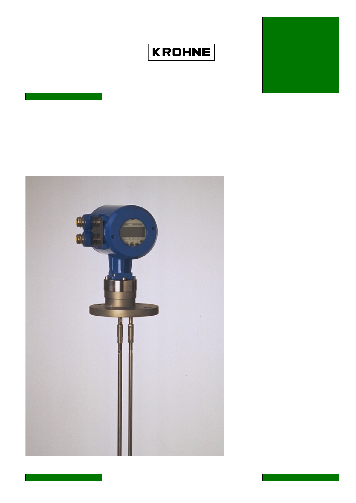
The BM100 is a two-wire transmitter with 4..20mA current output and HART® capability.
General characteristics of the BM100 HART® interface:
Multidrop Mode is supported.
•
Burst Mode is not supported.
•
Electrical connection (point-to-point or multidrop): refer to section
„Installation and Maintenance Manual. Reflex-Radar BM100“
BM100”
(section 11,
Communication Connection
).
and
Installation➪Wiring
„Service Manual. Reflex-Radar
of the
1.1 Configuring Instruments for Multidrop
There are differences in configuring instruments for multidrop mode from remote or via device
local keypad.
If the instrument is entering multidrop via HART® interface (any application can be used), i.e.
•
its bus address is changed from ‘0’ to any allowed, then all the necessary operations with the
instrument current output are done automatically (by the HART® transmitter).
If the instrument local keypad is used, the user must manually carry out the three assignments:
•
1. Set the desirable bus address (Fct. 1.6.2),
2. Set the first current output (primary current) range to “4 – 20 mA” (Fct. 1.3.2),
3. Switch the first current output function to “Off” (Fct. 1.3.1) and store configuration.
1.2 Device Unique HART® Address
It is worth noting that the Device Identification Number (defining the three low significant bytes of
the long frame device address) is derived from the ‘French Command Number’ parameter (Fct.
1.4.6, Ser. 3.4), but not from the device ‘Serial Number’ (Fct.1.4.5, Ser.3.3)!
2 HART® Transmitter Revisions and Instrument Firmware
2.1 Device Revisions
The BM100 HART® transmitter at a moment has only one revision:
noting that the contents of this document corresponds to the instrument
Device revision 1.
Firmware version 2.01+
for all the previous firmware versions the HART® interface support had just an intermediate
(development) state and could be delivered solely due to customer insistence.
2.2 DD Revisions
At a moment BM100 has the 3
The first one (having number ‘1’) corresponds to
•
DD revisions.
Firmware version 2.00,
was prepared under
HC275 Toolkit 3.5 and had just preliminary nature.
The second (‘2’) was produced under HC275 Toolkit 4.2. Changes within the DDL were caused
•
solely by the differences between tokenizers and are all around the DEFAULT-clause location
within enumerators’ lists.
The third (‘3’) is capable to work both with AMS and HC275, being the first version that is
•
prepared for official release. Registration at HCF pending.
© 2000 KROHNE Meßtechnik D-47058 Duisburg
It is wo rth
Page 3
-
Page 4

BM100 Remote Operation - HC 275 / AMS
Dev.-Rev. EE, DD-Rev. 03
3 HART® Communicator 275 (HC275)
3.1 Installation
The HC275 has to be programmed with the BM100 HART® Device Description (DD). Otherwise
the HC275 user will work with the instrument as with a generic one thus loosing opportunity for
entire instrument control.
3.2 Operating
Refer to the BM100 Menu Tree HC275 (Attachment A).
The BM100 operation via HC275 is made quite close to the manual instrument control via keypad.
The differences follows:
The instrument write protection (parameters “Entry Code 1”, “Code 1”, menu items 1.4.2, 1.4.3
•
of the
„Installation and Maintenance Manual. Reflex-Radar BM100”
of “Entry Code” method (item 3 ➪ 1 of the HC275 Menu Tree).
To “open” service functionality the user has to register as specialist. To do this, one should
•
invoke the “Service Code” method (item 3 ➪ 2 of the HC275 Menu Tree) and enter the correct
service password. After the HC275 is switched off (or the same method is invoked with
improper service password) specialist authorization is lost, and all service parameters/functions
again become inaccessible.
The two functions that are not accessible via instrument keypad but can be activated remotely
•
(recently – only by
PC-Star
application), namely “Measure Pulses” and “Linearity Calibration”,
are placed into “Configuration/Test” submenu (items 2 ➪ 1 ➪ 8 and 2 ➪ 3 ➪ 4
correspondingly).
The BM100 HART® transmitter makes it possible for the user to open a temporal session with
•
SMART protocol (say, to configure instrument via
PC-Star
). The protocol switch is undertaken
after invocation of “Switch to PC-Star” method (item 2 ➪ 1 ➪ 6 ➪ 3 of the HC275 Menu Tree).
After timeout (45 min) is expired or power on reset is performed, the instrument is turned back
to HART®.
For additional details refer to the
•
„HART® Smart Communications Protocol. BM100 Reflex-
Radar. Transmitter-Specific Command Specification“.
) is changed via invocation
3.3 Known HC275 (4.6) Shortcomings
When the “Save” operation is activated with the “Full (for PC)” data type chosen, HC275 loops
forever attempting to retrieve instrument Service Data. The loop can be avoided if the user has
registered as specialist in advance. With alternative data type (“Standard”) such preliminary
registration is not necessary.
© 2000 KROHNE Meßtechnik D-47058 Duisburg
Page 4
Page 5

BM100 Remote Operation - HC 275 / AMS
Dev.-Rev. EE, DD-Rev. 03
4 Asset Management Solutions (AMS)
4.1 Installation
Refer to the
•
and
“Wiring Diagrams”
AMS Configuration:
•
“AMS Installation Guide”
(appendix B).
(Fisher Rosemount):
“Installing Modems”
(section 5)
If the BM100 Device Description is not already installed on the AMS System an
„
BM100 Device Installation Kit“
(on floppy disk / CD-ROM from KROHNE) is needed.
For installing the DD with the Installation Kit refer:
AMS 1.3: to the
“AMS Installation Guide”
Descriptions for Field Devices” ➪ “Manually Installing Device Types”
AMS 1.4: to the
“AMS User’s Guide”
Types to AMS” ➪ “Install Device Types Manually”
(Fisher Rosemount), section 3 ➪
(Fisher Rosemount), section 4 ➪
.
“Installing Device
;
“Adding New Device
4.2 Operating
Refer to the BM100 Menu Tree AMS (Attachment B).
Some additional comments follow:
To “open” service functionality the user has to register as specialist. To do this, one should
•
invoke the
“Service Code”
password. Note, that after the
method from the
Device Context Menu
Device Connection View
and enter the correct service
is reopen (or the same method is invoked
with improper service password) specialist authorization is lost, and all service
parameters/functions (
EEPROM
As opposed to the HC275, handling of the Strap Table within AMS can be carried out in two
•
) again become inaccessible.
ways: besides the old scheme (
D/A trim, Linearity calibration, Reset user EEPROM, Reset factory
Strap table input, Strap table suppress
methods) it can be
controlled directly, from the three configuration displays. Due to transmitter implementation
peculiarities some steps should be sequentially undertaken to create or change the table from
configuration displays. The matter is that all the changes in table elements are initially
accumulated in instrument RAM. The trigger event that launches the table’s burning into
EEPROM, is Command #143 (Write Conversion Table Point Number) that deals with a single
parameter, being the ‘
Number of points
’ variable (configuration display “
Strap Table, 1-20
Just this command initiates the check of complete table and in case ‘twas successful – activates
the burning procedure. Worth noting that as soon as every table point depends on the ‘
of points
’ variable (in terms of VALIDITY clause), the latter is always written to instrument
before the points’ set. Hence while augmenting table the user will always be prompted “Error
‘Table not monotonous’ happened writing ‘Number of points’”. Only after this response the
table (changed elements) is copied to the instrument RAM. To burn it into EEPROM one have
to “change” again the number (say, 10 to 10, or 4 to 4) and press ‘Apply’ again. All the
commentaries above can be summarized as follows:
1. If the number of points is changed (with or without changes of the table contents), the user
should ignore the first possible error response after pressing ‘Apply’ (‘Table not monotonous’
happened writing ‘Number of points’), “change” the number of points again to desirable one
(i.e. reenter exactly the same value) and again press ‘Apply’.
2. If the number of points is preserved but some table items are changed, the user should press
‘Apply’ (thus transferring changed items to device), then reenter the number of points (as above)
and press ‘Apply’ again - otherwise the updated point(s) will be “in play” until the first power
reset.
”).
Number
© 2000 KROHNE Meßtechnik D-47058 Duisburg
Page 5
Page 6

BM100 Remote Operation - HC 275 / AMS
Dev.-Rev. EE, DD-Rev. 03
As compared with HC275 or
•
PC-Star
additional function, being the HART® Common-Practice
configuration tools, the BM100/AMS application has one
Apply values
method. The latter
assigns to the PV Upper/Lower Range Values the magnitude of the applied process.
Adjustment of the thresholds/gains (instrument’s functions 1.5.1, 1.5.4, Ser. 1.2.2) in the online
•
mode is possible only from methods (
Reference threshold/gain
). Such solution was caused by the two reasons: the threshold values
Level threshold/gain, Interface level threshold/gain,
are involved into bus transactions in internal instrument units (not engineering ones) and data
types; the threshold value that is advised for the user (i.e. should appear in the edit control)
depends both on the instrument’s dynamic and static data. To preserve for the user the
possibility to control these variables in the offline mode, the reconcile displays’ set is augmented
(as compared with configuration ones) by one tab, having the
Correspondingly, the
“Service”
reconcile tab is augmented by reference-related
“Application”
label.
thresholds/gains.
CAUTION:
While changing thresholds’ values in the offline mode, refer to the online help for
every variable.
4.3 Known AMS (1.4.x) Shortcomings
There are several problems found during trials with AMS. They are all reported to FRSI and will
probably have gone since the AMS release 1.5.
• User Configurations View
from either connected instrument or the
. When the user configuration is created (via drag & drop technology)
Plant Database
, not all configuration parameters (even
of the maintenance class) are transferred. The variables that cannot be obtained in the user
configuration, are the so-called conditional enumerators, if they depend on the instrument
identification data (delivered with Universal Command #0).
Say, allowed settings for ‘Range I 1’ and ‘Range I 2’ variables (enumerators) depend on the
instrument hardware version. As result, selection lists for both these variables will be empty in
the user
Losing of the “Service Code”. If after registration as specialist (refer to section 4.2), the user
•
does not open the
„Configuration Properties“
“Configuration Properties”
tabs.
or
“Process Variables”
window, AMS will lose
soon access to service functionality (i.e. the correct service code), and the user will have to
undertake the same actions (4.2) to re-establish access rights. In case if any window is already
open before the
“Service Code”
method is invoked, such loss doesn’t happen.
© 2000 KROHNE Meßtechnik D-47058 Duisburg
Page 6
Page 7

BM100 Remote Operation - HC 275 / AMS
(L)
Dev.-Rev. EE, DD-Rev. 03
Attachment A
1 Process
Variables
1 Measurements
2 Input/Outputs
BM100 Menu Tree HC275
1 AO1 Value
2 PV Percent of Range
3 AO2 Value
4 SV Percent of Range
1 Basis
Parameters
1 Level
2 Distance
3 Volume/Mass
4 Interface Level
5 Interface Distance
6 Interface Volume/
Mass
7 Ullage Volume/
Mass
8 Interface Layer
1 Tank Height
2 Hold Distance
3 Time Constant
4 Window Frozen
5 Level Window
6 Interface Window
7 Sensor Info
1 Snsr Upper Lim
2 Snsr Lower Lim
3 Snsr Min Span
2 Display
1 Operation
2 Configuration/
Test
3 Access
Rights
4 View Erros/
Warns (M)
5 HART
Variables
Designations:
- refer to the next page
(M) - method is invoked to retrieve/change data
(L) - local HC275 variable, that is not read/written to instrument
- subsists and
- not applicable if ‘Interface Option’ is disabled
- method's label and code depend on 'Measurement Mode' variable
2 Test
Outputs (M)
3 Service
1 Entry Code (M)
2 Service Code (M)
1 Manufacturer
2 Model
3 Fld dev rev
4 Software rev
5 Hardware rev
6 Dev id
7 Message
8 Descriptor
9 Date
10 Num resp preams
11 Polling address
is displayed only when the Strap Table exists
3 Signal Output
4 User Data
5 Application
6 Serial I/O
7 Strap Table
8 Measure
Pulses (M)
1 Function I1
2 Range I1
3 LRV I1
4 URV I1
5 Function I2
6 Range I2
7 LRV I2
8 URV I2
1 Language
2 Location
3 Serial number
4 French Cmd Nmb
5 German Cmd Nmb
6 Option
7 Probe Type
1 Level Thres. Gain
2 Distance Input (M)
3 Detection Delay
4 Int. Thres. Gain
5 Epsilon R
6 Interface Input
7 Settling
1 Baudrate
2 Address
3 Switch to PCStar
1 Volume unit
2 Input table (M)
3 Delete table (M)
(M)
(M)
KROHNE BM100 45f9ee03
1 Length Unit
2 Length format (L)
3 Volume Unit
4 Volume format
1 Dyn. Amplitude
2 Dyn. Gain
3 Adjust (M)
1 Dyn. Amplitude
2 Dyn. Gain
3 Adjust (M)
© 2000 KROHNE Meßtechnik D-47058 Duisburg
Page 7
Page 8

BM100 Remote Operation - HC 275 / AMS
Dev.-Rev. EE, DD-Rev. 03
Attachment A
(continued from the previous page)
1 Process
Variables
BM100 Menu Tree HC275
1 Basis
Parameters
1 Probe Length
2 Offset
3 Bottom Short-Cir.
4 Probe Position
5 Inter. Selection
2 Configuration/
Test
3 Access
Rights
4 View Erros/
Warns (M)
5 HART
Variables
1 Operation
2 Test
Outputs (M)
3 Service
1 Operation
2 Calibration
3 EEPROM
Reset
4 Linearity
Calibration (M)
2 Application
3 Serial I/O
1 Derivative Refer.
2 Calibration I1,I2
3 Elec. Cal. Speed
4 Mech. Cal. Speed
5 Air Epsilon R
1 EEPROM
User Reset (M)
2 EEPROM
Factory Reset (M)
3 Serial Number
4 French Cmd Nmb
5 German Cmd Nmb
(M)
1 Measurement Mode
2 Reference
1 Transmit
1 Dyn. Amplitude
2 Dyn. Gain
3 Adjust (M)
Designations:
- refer to the previous page
(M) - method is invoked to retrieve/change data
- method's label and code depend on 'Measurement Mode' variable
© 2000 KROHNE Meßtechnik D-47058 Duisburg
KROHNE BM100 45f9ee03
Page 8
Page 9

BM100 Remote Operation - HC 275 / AMS
Dev.-Rev. EE, DD-Rev. 03
Attachment B
BM100 Menu Tree AMS
Process Variables
Status
-----------------------------------
Diagnostics and Test
Calibrate
----------------------------------Master reset
Reset user EEPROM
Reset factory EEPROM
----------------------------------Entry Code
Service Code
----------------------------------Audit Trail
Drawing Notes ...
Help ...
----------------------------------Clear Offline Configuration
Compare Configurations
Configuration Properties
Measurements
•
Level
•
Distance
•
Volume/Mass
•
Interface Level
•
Interface Distance
•
Interface Volume/Mass
•
Ullage Volume/Mass
•
Interface Layer
Loop test
Overview
•
Primary variable out of limits
•
Non-primary variable out of limits
•
Primary variable analog output saturated
•
Primary variable analog output fixed
•
Cold start
•
Configuration changed
•
Field device malfunction
Analog Outputs
•
Analog Output 1 Value
•
PV Percent of Range
•
Analog Output 2 Value
•
SV Percent of Range
Calibration Management
----------------------------------D/A trim
Apply values
----------------------------------Linearity calibration
Measure pulses
----------------------------------Level threshold/gain
Interface level threshold/gain
Reference threshold/gain
----------------------------------Distance input
Interface distan ce input
----------------------------------Strap table input
Strap table suppress
Errors
Fatal errors
•
ADC reference error
•
ROM checksum error
•
RAM read/write error
•
EEPROM factory error
•
EEPROM user error
•
DAC error
•
Strap table error
Designations:
subsists and is displayed only when the Strap Table exists
-
- subsists and is displ ayed on ly when ‘Interface Option’ is enabled
- refer to the next page
Signal errors
•
Microwave error
•
No end of scan pulse
error
•
No reference pulse error
•
No level pulse error
•
No interface pulse error
•
Dead zone error
Warnings
•
Signal reference pulse
•
No level pulse
•
Level frozen
•
No interface level pulse
•
Interface frozen
KROHNE BM100 45f9ee03
© 2000 KROHNE Meßtechnik D-47058 Duisburg
Page 9
Page 10

BM100 Remote Operation - HC 275 / AMS
Dev.-Rev. EE, DD-Rev. 03
Attachment B
(continued from the previous page)
Process Variables
Status
-----------------------------------
Diagnostics and Test
Calibrate
----------------------------------Master reset
Reset user EEPROM
Reset factory EEPROM
----------------------------------Entry Code
Service Code
----------------------------------Audit Trail
Drawing Notes ...
Help ...
----------------------------------Clear Offline Configuration
Compare Configurations
Configuration Properties
BM100 Menu Tree AMS
Basic Setup
•
Location
----- Basic Functions -----
•
Tank Height
•
Hold Distance
•
Time Constant
•
Window Frozen
•
Level Window
•
Interface Window
------------- A01 ------------
•
Function I1
•
Scale I1 Max
•
Scale I1 Min
------------- A02 ------------
•
Function I2
•
Scale I2 Max
•
Scale I2 Min
Sensor
------------ Tank-------------
•
•
----------- Limits -----------
•
•
•
-------- Correction ---------
•
•
•
•
•
•
Designations:
- not applicable if 'Int erface Option' is disabled
(L) - Local AMS variable, that is not read/written to
instrument
* - Read-only variable
Process Input
•
Length Unit
•
Volume/Mass Unit
•
Time Constant
------ Display format ------
------ (AMS screens) -------
•
Level format (L)
•
Volume format (L)
Analog Outputs
------------- A01 ------------
Tank Height
Hold Distance
Snsr Upper Lim
Snsr Lo wer Lim
Snsr Min Span
Window Frozen
Level Window
Interface Window
Detection Delay
Epsilon R
Settling
•
Function I1
•
Range I1
•
Scale I1 Max
•
Scale I1 Min
•
AO Alarm type
------------- A02 ------------
•
Function I2
•
Range I2
•
Scale I2 Max
•
Scale I2 Min
•
AO Alarm type
Strap Table, 1-20
•
Number of points
First 20 pairs
Level ! Volume/Mass
Strap Table, 21-40
Next 20 pairs
Level ! Volume/Mass
Strap Table, 41-50
Last 10 pairs
Level ! Volume/Mass
© 2000 KROHNE Meßtechnik D-47058 Duisburg
Device
•
Model *
•
Manufacturer *
•
Fld dev rev *
•
Software rev *
•
Write protect *
--------- User Data ---------
•
Serial Number *
•
French Cmd Nmb *
•
German Cmd Nmb *
•
Option
•
Probe Type
HART
-- Device Identification --
•
Location
•
Device ID *
•
Date
•
Descriptor
•
Message
------ Protocol Data ------
•
Universal revision *
•
Num request preams *
•
Num response preams
•
Polling address
Service
---- Basis Parameters -----
•
Probe Length
•
Offset
•
Bottom Short-Cir.
•
Probe Position
•
Inter. Selection
------- Application ---------
•
Measurement Mode
------- Calibration ---------
•
Derivative Reference
•
Elec. Cal. Speed
•
Mech. Cal. Speed
•
Air Epsilon R
----------- Reset -------------
•
Serial Number
•
French Cmd Nmb
•
German C md Nmb
KROHNE BM100 45f9ee03
Page 10
 Loading...