

Page 1
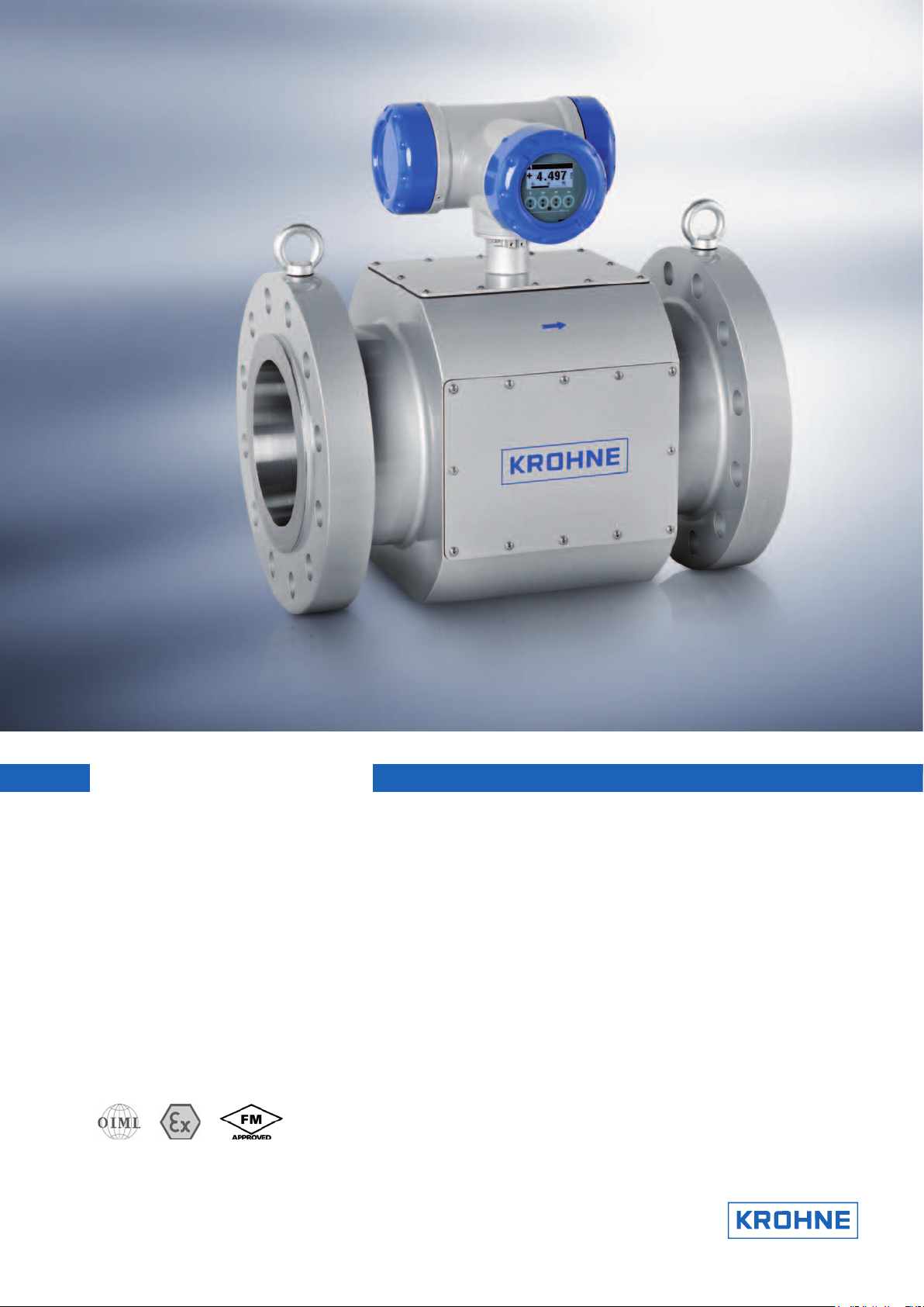
ALTOSONIC V12
Technical Datasheet
12-chord ultrasonic gas flowmeter for custody transfer
• 10-reflection chords for the highest possible accuracy; 2-reflection chords for
extra diagnosis options
• Built-in redundancy through dynamic chord substitution
• Performance monitoring and fouling detection
Page 2
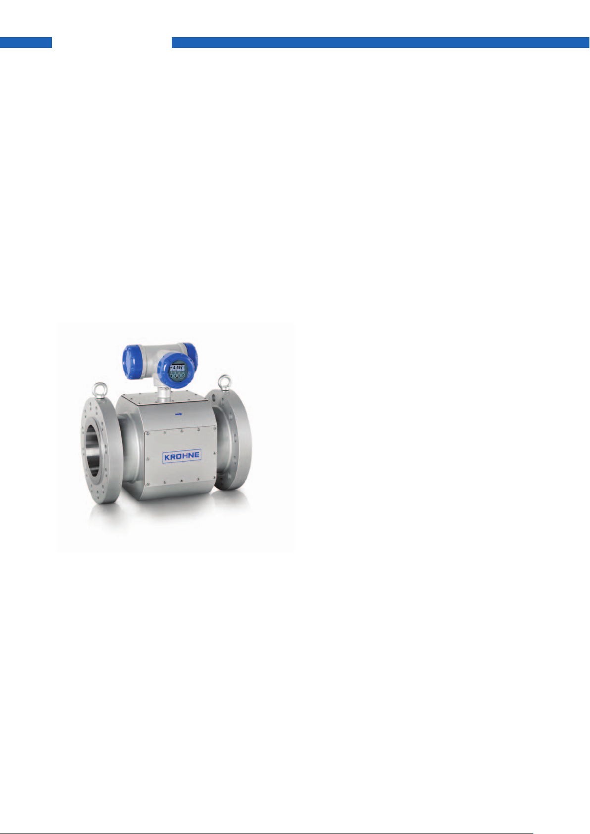
ALTOSONIC V12
Ultrasonic gas owmeter for custody transfer
As times change, so do the requirements for ultrasonic meters. Today it is assumed that an ultrasonic device
measures accurately and precisely, but what about long-term reliability? After all, this depends on more
than just the ultrasonic meter itself. The transferred effect of the high pressure calibration on the installation
conditions in the measuring station and dirt, which may collect on the meter over time, can also have a
negative effect.
The unique chord arrangement of the ALTOSONIC V12 enables it to generate diagnostic data for places
where traditional ultrasonic meters gathered too little information or none at all: rstly at the pipe wall itself,
scanning with reection. Secondly, in close proximity to the pipe wall, using the geometrical arrangement of
the outer chords. Thirdly, at the bottom of the pipe. This data is gathered using a separate diagnostic chord.
This extremely extensive diagnostic data allows the ALTOSONIC V12 to carry out self-monitoring, which sets
the standard for other devices in terms of performance monitoring.
Highlights
• 12-chord design
• High reliability with built-in redundancy
• Swirl compensation in each measuring plane
• Transducer replacement under pressure
• Bi-directional ow measurement
• Fully encapsulated cabling
• Field display for main functions
Industries
• Oil & Gas
• Petrochemical
Applications
• Offshore FPSO and platforms
• Onshore exploration
• Transmission
• Underground gas storage (UGS)
• Distribution
• Large gas intakes, for example for
power stations, petrochemical industry,
aluminum smelters, etc.
2 www.krohne-oilandgas.com
Page 3
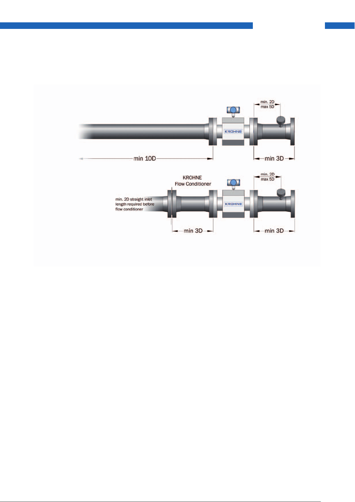
Inlet / outlet run requirements
Without Flow Conditioner
With KROHNE Flow Conditioner
ALTOSONIC V12
Under specic conditions ALTOSONIC V12 can be installed with just 5D
and no ow conditioner, please consult KROHNE if this option is required.
Where traditional ultrasonic ow meters typically require 10D straight inlet piping with a ow conditioner or
20D without a ow conditioner, ALTOSONIC V12 only requires 5D with ow conditioner or 10D without ow
conditioner. This not only minimizes the weight and footprint of the installation, but also saves on installation- and shipping costs, both during new installation as well as during re-calibration.
This much shorter installation length permits planning of more compact new metering runs and slot-in
replacement of conventional meters such as turbines during revamps.
3www.krohne-oilandgas.com
Page 4
ALTOSONIC V12
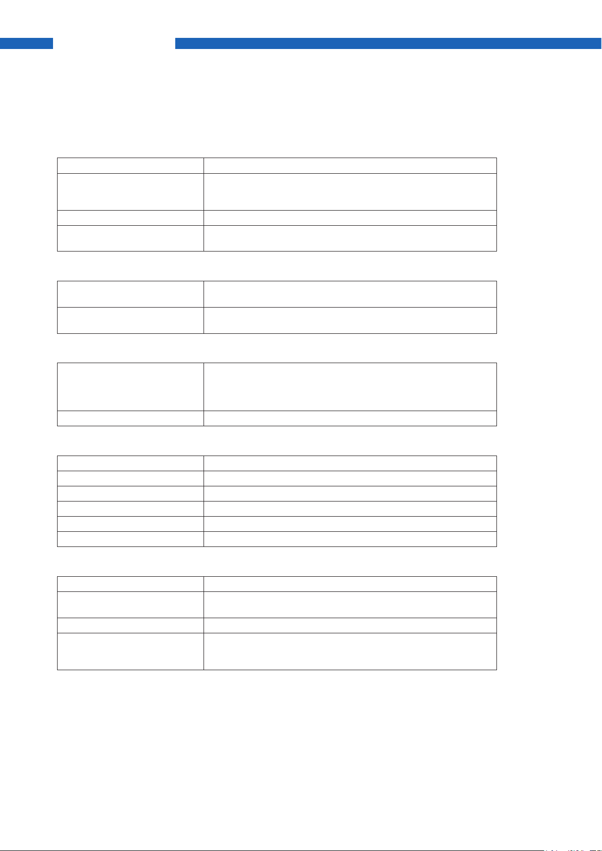
Functions
Device Ultrasonic gas owmeter
Description ALTOSONIC V12 consists of a meter body with ultrasonic transducers
and a converter box for signal processing and counter display mounted
on top of the meter body
Measurement functionality Actual volume ow rate and totalized volume; bi-directional
Applications Natural gas with a minimum of 75% methane, other applications on
request
Nominal diameter
[mm] 100,150,200,250,300,350,400,450,500,600,750, 00,1000,1200,1400,1600,
others on request
[inches] 4”, 6”, 8”, 10”, 12”, 14”, 16”, 18”, 20”, 24”, 30”, 36”, 40”,42”, 48”, 56”,
64”, others on request Other diameters on request
Measurement accuracy
Accuracy
(relative to calibration facility)
Repeatability ≤ ±0.1%
≤ ±0.5% of measured value, uncalibrated
≤ ±0.2% of measured value, high-pressure ow calibrated
≤ ±0.1% of measured value, high pressure ow calibrated and
linearized
Operating conditions
Flow range See ow table (last page)
Pressure 4...450 bar / 0.4...45 MPa / 60...6525 psi
Ambient temperature -40...+60°C / -40…+140°F
Process temperature -20...+100°C / -4…+212°F (-40…+100°C / -40…+212°F optional)
Wet gas content Contact KROHNE
content Contact KROHNE
CO
2
Materials
Flanges Low temperature carbon steel A350 LF2, stainless steel, duplex
Measuring tube Low temperature carbon steel A350 LF2 (≤ 12”) or A333 GR6 (≥ 14”),
stainless steel, duplex
Electronics housing Stainless steel A316
Finish Outside: 3-layer epoxy coating RAL 9006 (silver)
Inside: corrosion preservative oil lm
other nishes on request
4 www.krohne-oilandgas.com
Page 5

Electrical connection
Power supply 24 VDC / ≤10 W
Inputs / Outputs
without integrated diagnostics board
Digital output
Serial
Ethernet
Analog Output
Input
4x output
2x modbus over RS 485
Approvals
Custody transfer OIML R137 class 0.5 by NMi
MID (Measurement Instrument Directive 2004/22/EC) by NMi
Fully complaint to AGA 9 and ISO 17089
Hazardous Area ATEX:
IECEx:
CSA:
FM:
FM:
Protection IP 66 and NEMA 4X
NEMA 4x
II 2G Ex de ma IIB T5
Ex de ma IIB T5 Gb
Class I, Div 1 and 2, Groups B,C,D T6 …T4
and Class II, Div 1 and 2, Groups E,F,G
Class I, Div 2, Groups C, D T5
and Class II, Div 1, Groups E,F,G (Type 4X)
Class I, Zone 1, Aex de ma IIB T5, IP66
ALTOSONIC V12
with integrated diagnostics board
5x output
3x modbus over RS 485
2x Ethernet
1x 4-20 mA
1x multidrop (dual) HART
Verifications
Hydrostatic test (1.5xPdesign / 10min.) Standard; witnessing optional
Factory Acceptance Test (FAT) Standard; witnessing optional
Leakage test (1.1xPdesign / 30min.) Optional; witnessing optional
High pressure ow calibration Optional; witnessing optional
5www.krohne-oilandgas.com
Page 6

ALTOSONIC V12
Dimensions and weights (metric)
[mm] Øc min. Øc max. Øi H2 L W
100 102 107 96 520 300 330 119
150 154 160 144 570 450 380 198
200 202 207 191 620 600 430 301
250 254 261 239 660 750 470 417
300 303 312 284 740 900 540 706
350 333 340 312 780 1050 570 267
ASME 150
400 381 391 358 840 1200 620 375
450 428 442 405 890 1350 670 495
500 477 489 448 940 1500 720 666
600 574 591 540 1050 1800 820 1080
[mm] Øc min. Øc max. Øi H2 L W
100 102 107 96 520 300 330 129
150 154 160 144 570 450 380 218
200 202 207 191 620 600 430 331
250 254 261 239 680 750 470 465
300 303 312 284 760 900 540 740
350 333 340 312 810 1050 590 343
ASME 300
400 381 391 358 870 1200 650 465
450 428 442 405 920 1350 720 621
500 477 489 448 980 1500 780 814
600 574 591 540 1100 1800 920 1316
Weight
[kg]
Weight
[kg]
[mm] Øc min. Øc max. Øi H2 L W
100 97 105 96 520 400 330 140
150 146 158 144 575 450 375 248
200 193 205 191 630 600 425 376
250 242 258 239 710 750 510 548
300 289 308 284 780 900 560 836
350 317 337 312 815 1050 610 413
ASME 600
400 363 388 358 880 1200 690 590
450 409 435 405 930 1350 740 765
500 455 483 448 1000 1500 820 1003
600 547 581 540 1100 1800 940 1558
Measurements and weights are for reference only and might deviate depending
on schedule size.
6 www.krohne-oilandgas.com
Weight
[kg]
Page 7

Dimensions and weights (imperial)
ALTOSONIC V12
[inch] Øc min. Øc max. Øi H2 L W
4 4.02 4.21 3.78 20.47 11.81 12.99 262
6 6.06 6.30 5.67 22.44 17.27 14.96 436
8 7.95 8.15 7.52 24.41 23.62 16.93 664
10 10.00 10.28 9.41 25.98 29.53 18.50 919
12 11.93 12.28 11.18 29.13 35.43 21.26 1556
14 13.11 13.39 12.28 30.71 41.34 22.44 589
ASME 150
16 15.00 15.39 14.09 33.07 47.24 24.41 827
18 16.85 17.40 15.94 35.04 53.15 26.38 1091
20 18.78 19.25 17.64 37.01 59.06 28.35 1468
24 22.60 23.27 21.26 41.34 70.87 32.28 2381
[inch] Øc min. Øc max. Øi H2 L W
4 4.02 4.21 3.78 20.47 11.81 12.99 284
6 6.06 6.30 5.67 22.44 17.72 14.96 480
8 7.95 8.15 7.52 24.41 23.62 16.93 730
10 10.00 10.28 9.41 26.77 29.53 18.50 1025
12 11.93 12.28 11.18 29.92 35.43 21.26 1631
14 13.11 13.39 12.28 31.89 41.34 23.23 756
ASME 300
16 15.00 15.39 14.09 34.25 47.24 25.59 1025
18 16.85 17.40 15.94 36.22 53.15 28.35 1369
20 18.78 19.25 17.64 38.58 59.06 30.71 1795
24 22.60 23.27 21.26 43.31 70.87 36.22 2901
Weight
[lbs]
Weight
[lbs]
[inch] Øc min. Øc max. Øi H2 L W
4 3.82 4.13 3.78 20.47 15.75 12.99 309
6 5.75 6.22 5.67 22.64 17.72 14.76 547
8 7.60 8.07 7.52 24.80 23.62 16.73 829
10 9.53 10.16 9.41 27.95 29.53 20.08 1208
12 11.38 12.13 11.18 30.71 35.43 22.05 1846
14 12.48 13.27 12.28 32.09 41.34 24.02 910
ASME 600
16 14.29 15.28 14.09 34.65 47.24 27.17 1301
18 16.10 17.13 15.94 36.61 53.15 29.13 1687
20 17.91 19.02 17.64 39.37 59.06 32.28 2211
24 21.54 22.87 21.26 43.31 70.87 37.01 3435
Measurements and weights are for reference only and might deviate depending
on schedule size.
Weight
[lbs]
7www.krohne-oilandgas.com
Page 8

ALTOSONIC V12
Dimensions and weights (metric)
[mm] Øc min. Øc max. Øi H2 L W
100 97 103 96 520 400 330 152
150 146 155 144 590 450 390 273
200 193 203 191 660 600 470 431
250 242 255 239 730 750 550 605
300 289 304 284 810 1200 610 941
350 317 334 312 840 1050 650 519
400 363 381 358 890 1200 710 671
ASME 900 [mm]
450 409 429 405 960 1350 790 926
500 455 478 448 1020 1500 860 1190
600 547 575 540 1160 1800 1050 2128
[mm] Øc min. Øc max. Øi H2 L W
100 96 101 96 530 400 340 181
150 138 144 138 600 600 400 325
200 180 191 180 660 800 480 485
250 227 244 227 760 1000 580 795
300 269 294 269 860 1200 660 1240
350 295 325 295 940 1400 750 1585
ASME 1500
400 339 375 339 1000 1600 820 2050
450 381 425 381 1070 1800 910 tba
500 425 475 425 1130 2000 980 tba
600 509 575 509 1270 2400 1160 tba
Weight
[kg]
Weight
[kg]
[mm] Øc min. Øc max. Øi H2 L W
150 130 144 130 681 750 490 552
200 170 191 170 729 1000 550 825
250 213 244 213 844 1250 670 1505
ASME 2500
300 253 294 253 947 1500 750 2250
Measurements and weights are for reference only and might deviate depending
on schedule size.
8 www.krohne-oilandgas.com
Weight
[kg]
Page 9

Dimensions and weights (imperial)
ALTOSONIC V12
[inch] Øc min. Øc max. Øi H2 L W
4 3.82 4.06 3.78 20.47 15.75 12.99 335
6 5.75 6.10 5.67 23.23 17.72 15.35 602
8 7.60 7.99 7.52 25.98 23.62 18.50 950
10 9.53 10.04 9.41 28.74 29.53 21.65 1334
12 11.38 11.97 11.18 31.89 47.24 24.02 2075
14 12.48 13.15 12.28 33.07 41.34 25.59 1144
16 14.29 15.00 14.09 35.04 47.24 27.95 1479
ASME 900 [inch]
18 16.10 16.89 15.94 37.80 53.15 31.10 2041
20 17.91 18.82 17.64 40.16 59.06 33.86 2623
24 21.54 22.64 21.26 45.67 70.87 41.34 4691
[inch] Øc min. Øc max. Øi H2 L W
4 3.77 3.98 3.77 20.87 15.75 13.39 399
6 5.41 5.67 5.41 23.62 23.62 15.75 717
8 7.07 7.50 7.07 25.97 31.50 18.90 1069
10 8.92 9.60 8.92 29.92 39.37 22.83 1753
12 10.58 11.56 10.58 33.86 47.24 25.98 2734
14 11.63 12.80 11.63 37.01 55.12 29.53 3495
ASME 1500
16 13.35 14.76 13.35 39.37 62.99 32.28 4520
18 15.01 16.73 15.01 42.13 70.87 35.83 tba
20 16.73 18.70 16.73 44.49 78.74 38.58 tba
24 20.06 22.64 20.06 50.00 94.49 45.67 tba
Weight
[lbs]
Weight
[lbs]
[inch] Øc min. Øc max. Øi H2 L W
6 5.11 5.67 5.11 26.80 29.53 19.29 1217
8 6.71 7.50 6.71 28.68 39.37 21.65 1819
10 8.37 9.60 8.37 33.21 49.21 26.38 3318
ASME 2500
Measurements and weights are for reference only and might deviate depending
on schedule size.
12 9.97 11.56 9.97 37.27 59.06 29.53 4961
Weight
[lbs]
9www.krohne-oilandgas.com
Page 10

ALTOSONIC V12
Flow Table
Size [mm] Size [inch]
100 4 25 1,000
150 6 45 2,300
200 8 75 4,100
250 10 110 6,200
300 12 140 8,200
350 14 170 9,700
400 16 210 11,700
450 18 240 13,900
500 20 260 15,700
600 24 285 21,400
700 28 450 30,000
750 30 650 44,000
800 32 800 55,000
900 36 880 58,000
950 38 1,200 75,000
1000 40 1,600 94,000
1050 42 2,100 117,000
1200 48 1,200 75,000
1400 56 1,600 94,000
1600 64 2,100 117,000
Qmin Qmax
[m3/h]
Qt = 0.1*Qmax
For piping > Sch 80 values may vary slightly. Calculations shall be used as an indication.
Please ask KROHNE Engineering for detailed sizing.
10 www.krohne-oilandgas.com
Page 11

ALTOSONIC V12
11www.krohne-oilandgas.com
Page 12

KROHNE Oil & Gas
Overview
Systems
• Flowmeters for custody transfer
• Liquid owmetering systems
• Gas owmetering systems
• Wet gas metering systems
• Provers & master meters
• Flow computing, supervisory software &
analyzer management
• Calibration systems
• Tank inventory & management systems
• Analyzer houses and shelters
• Loading & off-loading systems
• Leak detection and localisation systems
• Revamps & upgrades
• Testing, installation, commissioning,
service training
Products
• Gas ultrasonic owmeters for custody transfer
• Liquid ultrasonic owmeters for custody transfer
• Mass owmeters for custody transfer
• Venturis for wet gas metering
• Prover sphere detectors
• Flow computers
• Supervisory systems
• Meter validation software packages
• Electromagnetic owmeters
• Level measuring instruments
• Variable area owmeters
• Temperature measuring instruments
• Pressure measuring instruments
• Analyzers
• Vortex owmeters
• Flow controllers
Contact
Head ofce KROHNE Oil & Gas
KROHNE Oil & Gas B.V.
Minervum 7441
4817 ZG LH Breda
The Netherlands
Tel.: +31 76 711 200 0
Fax: +31 76 711 200 1
koginfo@krohne-oilandgas.com
Global companies and representatives
The current list of all
KROHNE contacts and
addresses can be found at:
© KROHNE11/2011 - All rights reserved
Subject to change without notice - Errors and omissions excepted
www.krohne-oilandgas.com
 Loading...