

Page 1
Handbook
Handbook
ALTOSONIC V12
ALTOSONIC V12
ALTOSONIC V12ALTOSONIC V12
12-chord ultrasonic gas flowmeter for custody transfer
HandbookHandbook
© KROHNE 04/2013 - 4002643502 - MA ALTOSONIC V12 R02 en
Page 2

: IMPRINT :::::::::::::::::::::::::::::::::::::::
All rights reserved. It is prohibited to reproduce this documentation, or any part thereof, without
the prior written authorisation of KROHNE Messtechnik GmbH.
Subject to change without notice.
Copyright 2013 by
KROHNE Messtechnik GmbH - Ludwig-Krohne-Str. 5 - 47058 Duisburg (Germany)
2
www.krohne.com 04/2013 - 4002643502 - MA ALTOSONIC V12 R02 en
Page 3

ALTOSONIC V12
CONTENTS
1 Safety instructions 7
1.1 Intended use ..................................................................................................................... 7
1.2 Certifications .................................................................................................................... 7
1.3 Safety instructions from the manufacturer ..................................................................... 8
1.3.1 Copyright and data protection ................................................................................................ 8
1.3.2 Disclaimer ............................................................................................................................... 8
1.3.3 Product liability and warranty ................................................................................................ 9
1.3.4 Information concerning the documentation........................................................................... 9
1.3.5 Warnings and symbols used................................................................................................. 10
1.4 Safety instructions for the operator............................................................................... 10
2 Device description 11
2.1 Scope of delivery............................................................................................................. 11
2.2 Hardware description..................................................................................................... 11
2.2.1 Transducers .......................................................................................................................... 12
2.2.2 The electronic unit ................................................................................................................ 13
2.3 Software description ...................................................................................................... 14
2.4 Nameplates .................................................................................................................... 15
3 Installation 17
3.1 Notes on installation ......................................................................................................17
3.2 Storage ........................................................................................................................... 17
3.3 Transport ........................................................................................................................ 18
3.4 Pre-installation requirements ....................................................................................... 19
3.5 Installation...................................................................................................................... 19
3.5.1 Mounting position.................................................................................................................. 19
3.5.2 Pipe diameters and lengths.................................................................................................. 20
3.5.3 Flow conditioners.................................................................................................................. 20
3.5.4 Inlet and outlet for uni-directional use ................................................................................ 20
3.5.5 Control valves........................................................................................................................ 21
3.5.6 P and T sensors..................................................................................................................... 22
3.6 Temperatures ................................................................................................................. 23
4 Electrical connections 24
4.1 Safety instructions.......................................................................................................... 24
4.2 Opening and closing covers ........................................................................................... 24
4.3 Digital I/O connections ................................................................................................... 25
4.3.1 Pulse and frequency output.................................................................................................. 26
4.3.2 Status outputs ....................................................................................................................... 26
4.3.3 Emulation of a turbine meter ............................................................................................... 27
4.4 Serial data communication (RS 485).............................................................................. 28
4.5 Power connection ...........................................................................................................28
4.6 Cabling............................................................................................................................ 29
4.7 Grounding ....................................................................................................................... 30
www.krohne.com04/2013 - 4002643502 - MA ALTOSONIC V12 R02 en
3
Page 4

CONTENTS
ALTOSONIC V12
5 Start-up 31
5.1 Starting the signal converter ......................................................................................... 31
6 Operation 32
6.1 Display and operating elements .................................................................................... 32
6.1.1 Display in measuring mode with 2 or 3 measured values ................................................... 33
6.2 Menu overview................................................................................................................ 34
6.3 Access control and seals................................................................................................ 35
7 Software service tool 37
7.1 Introduction .................................................................................................................... 37
7.2 Installation of the software ............................................................................................ 37
7.3 Starting a session........................................................................................................... 37
7.4 Loading a monitoring configuration............................................................................... 42
7.5 Changing and saving a monitoring configuration .......................................................... 45
7.5.1 Creating a monitoring configuration .................................................................................... 45
7.5.2 Saving a monitoring configuration with a new name ........................................................... 48
7.5.3 Saving a monitoring configuration with its current name ................................................... 49
7.6 Creating a monitoring configuration.............................................................................. 50
7.7 Viewing data.................................................................................................................... 52
7.7.1 Unformatted data.................................................................................................................. 53
7.8 Customizing the way data is presented ......................................................................... 54
7.8.1 Setting up tabs in the user view window .............................................................................. 54
7.8.2 Creating a new grid definition............................................................................................... 56
7.8.3 Creating a new graphical presentation ................................................................................ 60
7.9 Creating reports ............................................................................................................. 61
7.9.1 Reporting related to parameter settings ............................................................................. 61
7.9.2 Reporting related to process values .................................................................................... 66
7.9.3 Reporting related to calibration parameters .......................................................................66
7.9.4 Reporting related to privileges............................................................................................. 66
7.10 Logging data from a flowmeter.................................................................................... 66
7.11 Customizing the data logging process......................................................................... 67
7.12 Adjusting parameter settings....................................................................................... 72
8 Service 73
8.1 Periodic maintenance..................................................................................................... 73
8.2 Cleaning.......................................................................................................................... 73
8.3 Exchange of transducers................................................................................................ 74
8.4 Exchange of transducers - Depressurised condition .................................................... 74
8.5 Exchange of transducers - Pressurised condition ........................................................ 79
8.5.1 Transducer retraction tool.................................................................................................... 81
8.5.2 Procedure to remove a transducer ...................................................................................... 82
8.6 Exchange of electronics unit .......................................................................................... 94
8.6.1 Field version.......................................................................................................................... 94
8.7 Battery maintenance ...................................................................................................... 96
8.8 Availability of services .................................................................................................... 96
4
www.krohne.com 04/2013 - 4002643502 - MA ALTOSONIC V12 R02 en
Page 5

ALTOSONIC V12
CONTENTS
8.9 Returning the device to the manufacturer..................................................................... 96
8.9.1 General information.............................................................................................................. 96
8.9.2 Form (for copying) to accompany a returned device............................................................ 97
8.10 Disposal ........................................................................................................................ 97
9 Technical data 98
9.1 Measuring principle........................................................................................................98
9.2 Transit time measuring principle .................................................................................. 98
9.3 Swirl compensation........................................................................................................ 99
9.4 Multipath ultrasonic flowmeters.................................................................................. 100
9.5 Technical data table ..................................................................................................... 101
9.6 Dimensions and weights .............................................................................................. 105
9.7 Flow table ..................................................................................................................... 110
10 Modbus protocol description and set-up 111
10.1 Introduction ................................................................................................................ 111
10.2 Physical Communication Layer.................................................................................. 111
10.3 Serial transmission format ........................................................................................ 112
10.3.1 ASCII mode........................................................................................................................ 112
10.3.2 RTU mode.......................................................................................................................... 113
10.4 Modbus message framing.......................................................................................... 113
10.4.1 Address Field (Device Address)........................................................................................ 114
10.4.2 Function Field ................................................................................................................... 114
10.4.3 Data Field .......................................................................................................................... 114
10.4.4 Error checking methods ................................................................................................... 114
10.4.5 Transmission gaps............................................................................................................ 115
10.4.6 Time out............................................................................................................................. 115
10.5 Supported functions ................................................................................................... 115
10.5.1 Function 01: READ COILS ................................................................................................. 116
10.5.2 Function 02: READ DISCRETE INPUTS............................................................................. 116
10.5.3 Function 03: READ HOLDING REGISTERS........................................................................ 117
10.5.4 Function 04: READ INPUT REGISTERS............................................................................. 117
10.5.5 Function 05: WRITE SINGLE COIL .................................................................................... 118
10.5.6 Function 06: WRITE SINGLE HOLDING REGISTER........................................................... 118
10.5.7 Function 08: DIAGNOSTICS............................................................................................... 118
10.5.8 Function 15: WRITE MULTIPLE COILS ............................................................................. 119
10.5.9 Function 16: WRITE MULTIPLE HOLDING REGISTERS.................................................... 119
10.5.10 Exception responses ....................................................................................................... 120
10.6 Handling of large data types ...................................................................................... 121
10.6.1 Integer (16 bit), Transmit sequence.................................................................................. 122
10.6.2 Long integer (32 bit), Transmit Sequence ........................................................................ 122
10.6.3 Single precision floating point (32 bit), transmit sequence ............................................. 123
10.6.4 Double precision floating point (64 bit), transmit sequence ............................................ 124
10.6.5 Long long (64 bit integer), transmit sequence ................................................................. 125
10.6.6 Maximum number requested items ................................................................................. 125
10.7 Default settings ..........................................................................................................126
10.8 Modbus register mapping .......................................................................................... 127
10.8.1 Input Registers (read-only): Integer (16-bit); address range 3000-3499 ........................ 127
10.8.2 Holding Registers (read/write): Integer (16-bit); address range 3500-3999................... 127
10.8.3 Input Registers (read-only): Long integer (32-bit); address range 5000-5499 ............... 128
www.krohne.com04/2013 - 4002643502 - MA ALTOSONIC V12 R02 en
5
Page 6

CONTENTS
10.8.4 Holding Registers (read/write): Long integer (32-bit), addres range 5500-5999............ 132
10.8.5 Input Registers (read-only): Double (64-bit floating point), address range 6000-6499 .. 133
10.8.6 Holding Registers (read/write): Double (64-bit floating-point), addr. range 6500-6999. 133
10.8.7 Input Registers (read-only): Float (32-bit floating-point), address range 7000-7499..... 133
10.8.8 Holding Registers (read/write): Float (32-bit) floating-point, address range 7500-7999 138
10.8.9 Input Registers (read-only): Long long (64-bit integer), address range 8000-8499........ 141
10.8.10 Holding Registers (read/write): Long long (64-bit integer), address range 8500-8999 142
ALTOSONIC V12
11 Notes 143
6
www.krohne.com 04/2013 - 4002643502 - MA ALTOSONIC V12 R02 en
Page 7
ALTOSONIC V12
1.1 Intended use
The ALTOSONIC V12 is a gas flowmeter for custody transfer applications.
The meter is suitable to operate at least under the following conditions:
• relative density from 0.55 and upwards
• methane concentrations 75...100%
CAUTION!
High levels of CO
absorption properties. It is recommended to submit a specification of the process medium to be
measured at the manufacturer for advice.
1.2 Certifications
LEGAL NOTICE!
The ALTOSONIC V12 custody transfer gas flowmeter meets the technical requirements and
standards applicable to equipment designed for use in different countries world wide.
SAFETY INSTRUCTIONS 1
can inhibit the operation of an ultrasonic flowmeter due to its acoustic
2
European Union (EU):
European Union (EU):
European Union (EU):European Union (EU):
• Pressure Equipment Directive 97/23/EC
• EMC directive 2004/108/EC, according to:
EN 50081-2
EN 61000-6 (part 1, 2 and 3)
EN 61326-1 (1997) and A1 (1998), A2 (2001)
• ATEX directive 94/9/EC according to:
EN 60079-0 (2006)
EN 60079-1 (Ex 'd')
EN 60079-7 (Ex 'e')
EN 60079-18 (Ex 'ma')
• Custody transfer approvals according to:
MID directive 2004/22/EC ((MID = Measurement Instrument Directive)
OIML R137-1 (International Organization for Legal Metrology)
• Fully compliant to AGA 9
• Fully compliant to ISO 17089
America:
America:
America:America:
• Certified for use in potentially explosive atmospheres according to FM:
FM3600
FM3615
Canada:
Canada:
Canada:Canada:
• CRN
• Certified for use in potentially explosive atmospheres according to CSA:
C22.2 No. 30
C22.2 No. 0.4
www.krohne.com04/2013 - 4002643502 - MA ALTOSONIC V12 R02 en
7
Page 8

1 SAFETY INSTRUCTIONS
Other standards:
Other standards:
Other standards:Other standards:
• IECEx PTB 10.0013X
INFORMATION!
Not all country specific approvals are listed here. Please consult KROHNE in case of a specific
approval that is not listed here.
1.3 Safety instructions from the manufacturer
1.3.1 Copyright and data protection
The contents of this document have been created with great care. Nevertheless, we provide no
guarantee that the contents are correct, complete or up-to-date.
The contents and works in this document are subject to copyright. Contributions from third
parties are identified as such. Reproduction, processing, dissemination and any type of use
beyond what is permitted under copyright requires written authorisation from the respective
author and/or the manufacturer.
ALTOSONIC V12
The manufacturer tries always to observe the copyrights of others, and to draw on works created
in-house or works in the public domain.
The collection of personal data (such as names, street addresses or e-mail addresses) in the
manufacturer's documents is always on a voluntary basis whenever possible. Whenever
feasible, it is always possible to make use of the offerings and services without providing any
personal data.
We draw your attention to the fact that data transmission over the Internet (e.g. when
communicating by e-mail) may involve gaps in security. It is not possible to protect such data
completely against access by third parties.
We hereby expressly prohibit the use of the contact data published as part of our duty to publish
an imprint for the purpose of sending us any advertising or informational materials that we have
not expressly requested.
1.3.2 Disclaimer
The manufacturer will not be liable for any damage of any kind by using its product, including,
but not limited to direct, indirect or incidental and consequential damages.
This disclaimer does not apply in case the manufacturer has acted on purpose or with gross
negligence. In the event any applicable law does not allow such limitations on implied warranties
or the exclusion of limitation of certain damages, you may, if such law applies to you, not be
subject to some or all of the above disclaimer, exclusions or limitations.
Any product purchased from the manufacturer is warranted in accordance with the relevant
product documentation and our Terms and Conditions of Sale.
The manufacturer reserves the right to alter the content of its documents, including this
disclaimer in any way, at any time, for any reason, without prior notification, and will not be liable
in any way for possible consequences of such changes.
8
www.krohne.com 04/2013 - 4002643502 - MA ALTOSONIC V12 R02 en
Page 9

ALTOSONIC V12
1.3.3 Product liability and warranty
The operator shall bear responsibility for the suitability of the device for the specific purpose.
The manufacturer accepts no liability for the consequences of misuse by the operator. Improper
installation and operation of the devices (systems) will cause the warranty to be void. The
respective "Standard Terms and Conditions" which form the basis for the sales contract shall
also apply.
1.3.4 Information concerning the documentation
To prevent any injury to the user or damage to the device it is essential that you read the
information in this document and observe applicable national standards, safety requirements
and accident prevention regulations.
If this document is not in your native language and if you have any problems understanding the
text, we advise you to contact your local office for assistance. The manufacturer can not accept
responsibility for any damage or injury caused by misunderstanding of the information in this
document.
This document is provided to help you establish operating conditions, which will permit safe and
efficient use of this device. Special considerations and precautions are also described in the
document, which appear in the form of underneath icons.
SAFETY INSTRUCTIONS 1
www.krohne.com04/2013 - 4002643502 - MA ALTOSONIC V12 R02 en
9
Page 10
1 SAFETY INSTRUCTIONS
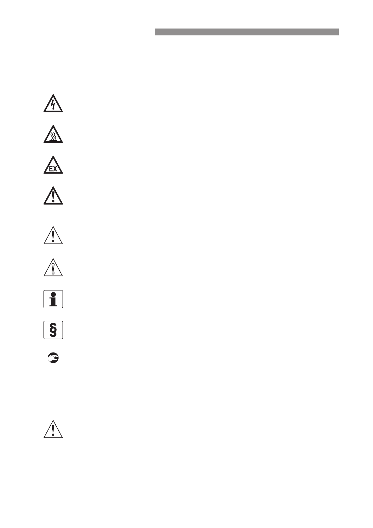
1.3.5 Warnings and symbols used
Safety warnings are indicated by the following symbols.
DANGER!
This information refers to the immediate danger when working with electricity.
DANGER!
This warning refers to the immediate danger of burns caused by heat or hot surfaces.
DANGER!
This warning refers to the immediate danger when using this device in a hazardous atmosphere.
DANGER!
These warnings must be observed without fail. Even partial disregard of this warning can lead to
serious health problems and even death. There is also the risk of seriously damaging the device
or parts of the operator's plant.
ALTOSONIC V12
WARNING!
Disregarding this safety warning, even if only in part, poses the risk of serious health problems.
There is also the risk of damaging the device or parts of the operator's plant.
CAUTION!
Disregarding these instructions can result in damage to the device or to parts of the operator's
plant.
INFORMATION!
These instructions contain important information for the handling of the device.
LEGAL NOTICE!
This note contains information on statutory directives and standards.
• HANDLING
HANDLING
HANDLINGHANDLING
This symbol designates all instructions for actions to be carried out by the operator in the
specified sequence.
i RESULT
RESULT
RESULTRESULT
This symbol refers to all important consequences of the previous actions.
1.4 Safety instructions for the operator
10
WARNING!
In general, devices from the manufacturer may only be installed, commissioned, operated and
maintained by properly trained and authorized personnel.
This document is provided to help you establish operating conditions, which will permit safe and
efficient use of this device.
www.krohne.com 04/2013 - 4002643502 - MA ALTOSONIC V12 R02 en
Page 11
ALTOSONIC V12
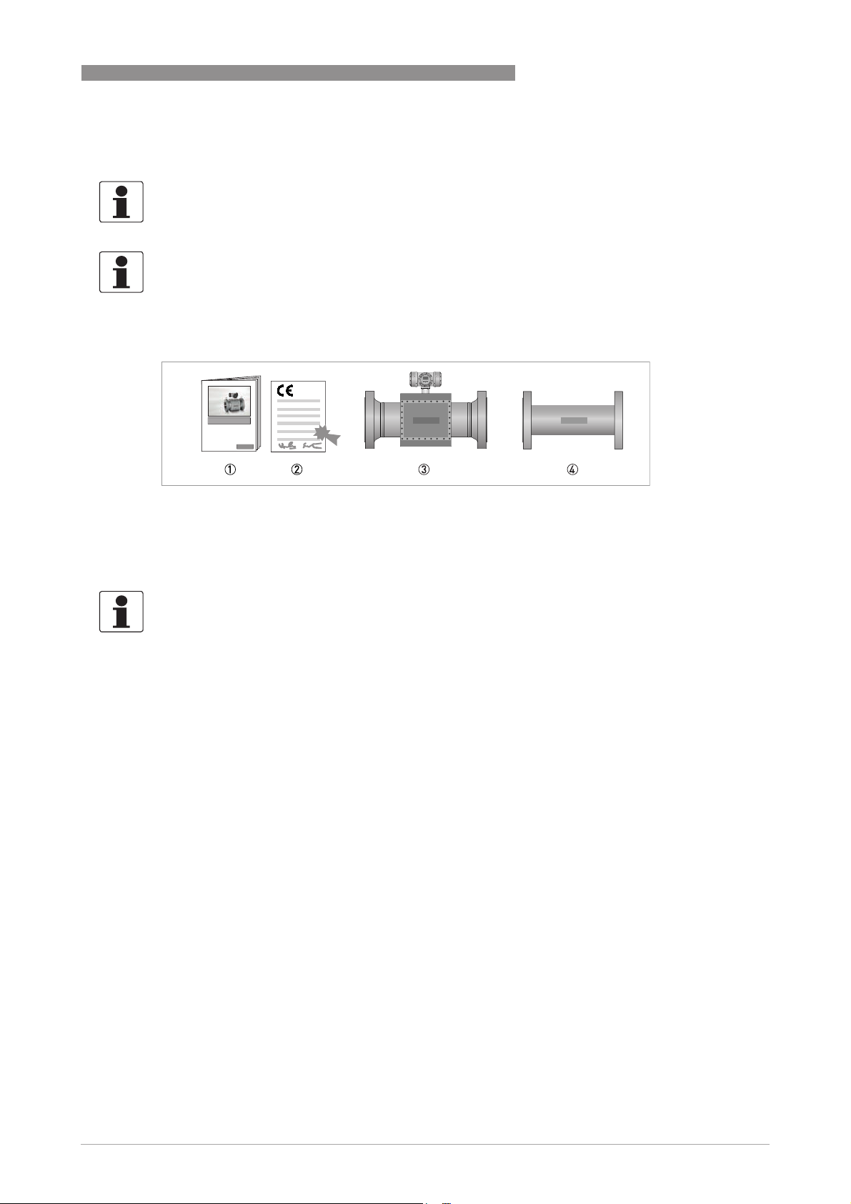
2.1 Scope of delivery
INFORMATION!
Do a check of the packing list to make sure that you have all the elements given in the order.
INFORMATION!
The instrument is delivered in a seaworthy, reinforced wooden crate. Inspect the packing
carefully for damages or signs of rough handling. Report damage to the carrier and to the local
office of the manufacturer.
DEVICE DESCRIPTION 2
Figure 2-1: Scope of delivery
1 Product documentation
2 CE Declaration
3 Flowmeter in ordered version
4 Optional: flow conditioner, spare parts and / or installed impact indicators
INFORMATION!
Calibration reports and project specific documents are in the meter's databook that is sent
separately.
2.2 Hardware description
The flowmeter is designed to meet explosion safety requirements based on:
• the application of an explosion proof (Ex d) electronics enclosure according to IEC 60079-1
• using Ex certified transducers according to IEC 60079-18
• using cables with an Ex d certified connector according to IEC 60079-1 to connect to the
transducers
• installation of the cabling between the electronics and the transducers complying with
enhanced safety
enhanced safety requirements according to IEC 60079-7.
enhanced safetyenhanced safety
The flowmeter consists of a meter body with one or two (twin meter) electronic units installed on
top of it.
For smaller diameters the meter body is fully machined hence no welding is done.
For larger diameters the meter body is a welded construction.
www.krohne.com04/2013 - 4002643502 - MA ALTOSONIC V12 R02 en
11
Page 12

2 DEVICE DESCRIPTION
A series of acoustic transducer are installed on the inside of the meter body. Each pair of
ultrasonic transducers forms an acoustic measurement path. The acoustic measurement path
consists of one (direct) chord or two (reflective) chords.
The chords in the horizontal plane are used for flow measurement, the chords in the vertical
plane are used for diagnostics only. The reflective chords that are offset from the meter’s centre
line use acoustic mirrors to reflect the ultrasonic signal. The reflective chords that are in the
centre line of the meter reflect directly on the pipe wall. Direct chords do not reflect and
therefore do not require acoustic mirrors.
The transducers are electrically connected to the electronic unit on top of the meter by means of
coaxial cables. The cabling is protected against mechanical damage and moisture by means of
covers. The coaxial cables enter the electronics enclosure through its “foot” (or support). In this
foot an Ex d approved cable feed through is installed that closes this entry to the electronics
enclosure.
On the other side the coax cables are connected to the transducers, this connection is also done
by an Ex d approved connector
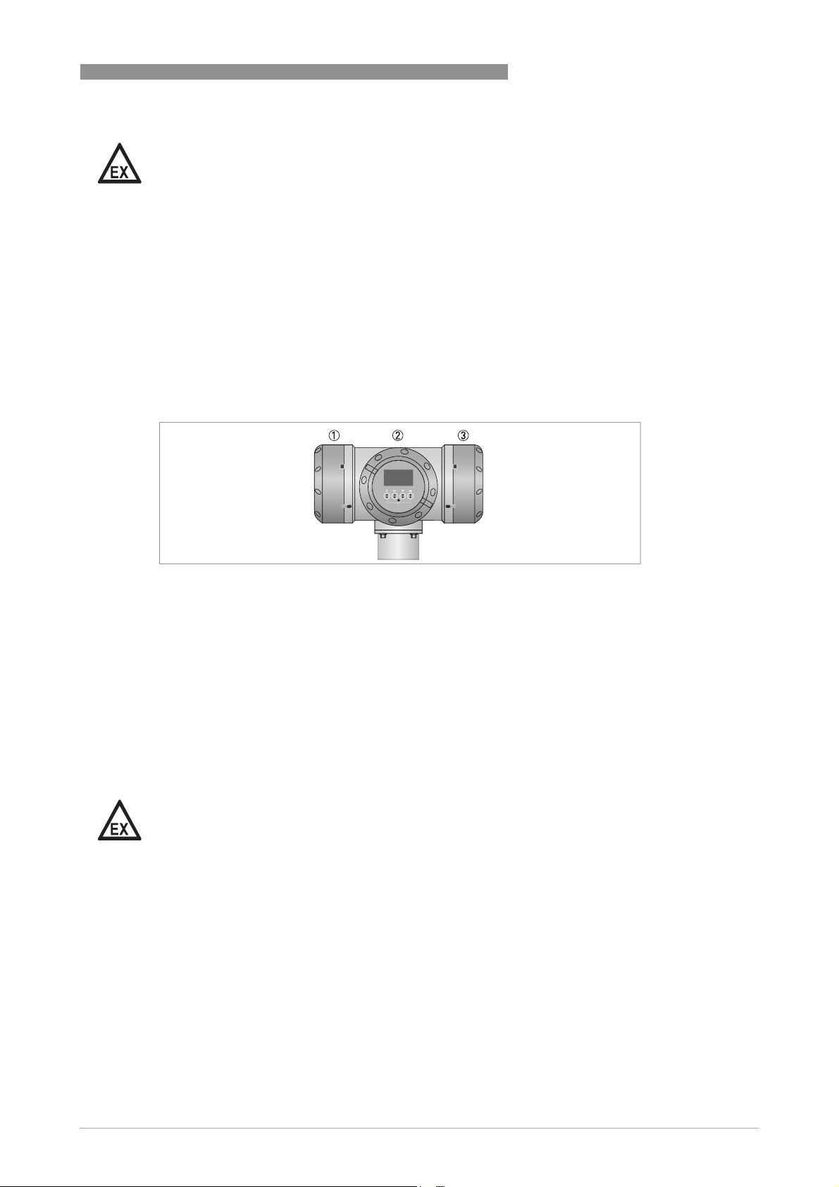
ALTOSONIC V12
Figure 2-2: Location of sensors and electronic unit
2.2.1 Transducers
Acoustic signals are transmitted and received by means of ultrasonic transducers. The active
part of an ultrasonic transducer is a small disk of piëzo electric ceramic in the front of the
transducer. It is packaged (sealed) in a construction of metal parts and high grade epoxy or
inside a titanium housing. The front side of the transducer is exposed to the gas to be measured,
this results in the best efficiency for transmitting and receiving ultrasound.
Overview installation of transducer
Figure 2-3: Sensor assembly
1 Double O-ring
2 Slot in the socket
3 Ex-d socket
4 Ex-d plug
5 Alignment pin
6 Cap
7 Securing screw M2
8 Coaxial wire
9 Transducer nut
12
www.krohne.com 04/2013 - 4002643502 - MA ALTOSONIC V12 R02 en
Page 13
ALTOSONIC V12
DANGER!
The transducers have an Ex-d socket (socket, 3) that connects to an Ex-d plug 4 which
terminates a coaxial wire 8.
An alignment pin 5 on the connector engages with a slot in the Ex-d socket 2, this ensures that
the transducer is connected with the correct polarity. The cap 6, screwed on the Ex-d socket,
fastens the connector, a small securing screw (M2) 7 secures this cap. The transducers are
fastened in the meter body using a transducer nut with a hole in the centre 9. A double O-ring
1 seals the pressure inside the piping effectively from the outside world.
2.2.2 The electronic unit
The housing consists of three compartments. Each compartment has a removable cover that
gives access to the inside, in order to connect external wiring or to install or to replace
components.
DEVICE DESCRIPTION 2
Figure 2-4: Converter housing
1 Power supply / RS485 compartment / Optional diagnostics board
2 Electronics compartment
3 Connection compartment
Connection compartment
The compartment on the right side is the connection compartment, which contains only a block
with screw terminals. Signal wires from and to the electronics compartment are connected to
this terminal block. Wiring to other (external/auxiliary) equipment can be connected to the screw
terminals in this compartment.
Cables can enter this compartment through cable glands installed in either one of three
threaded holes M20x1.5.
DANGER!
Unused holes must be closed with Ex d approved blind stops.
Power supply / RS485 compartment
The compartment on the left side is used to install the power converter. This board also includes
two serial data ports (RS485). As an option an additional diagnostics processor board can be
installed. Wiring to external equipment or to a power source is attached to connectors with
screw terminals. These connectors engage directly with matching parts on the printed cicuit
boards.
Cables can enter this compartment through cable glands installed in either one of three
threaded holes M20x1.5.
www.krohne.com04/2013 - 4002643502 - MA ALTOSONIC V12 R02 en
13
Page 14
2 DEVICE DESCRIPTION
Electronics compartment
The compartment on the front has a cover with a glass window. It contains a frame with a
number of printed circuit boards. The boards have the following functions:
• Frequency and status output board
• Processor boards
• Sensor driver board
• Display module (connected tot the front side of the frame, can be seen through the cover with
the glass window)
2.3 Software description
The ALTOSONIC V12 contains a powerful microprocessor that controls the functions and
calculations it performs. The microprocessor executes program code consisting of several
modules, according to the functions it has to perform. By means of a set of parameters the
software can be configured to various sizes and models of flowmeters and according to specific
requirements depending of applications or customers.
ALTOSONIC V12
LEGAL NOTICE!
The parameters are stored in a configuration file. Configuration parameters are password
protected in order to prevent unauthorized modification. Access in order to read, view and
inspect parameter values is unrestricted.
Individual parameters are classified according to “roles” in order to define differentiated access
rights. Each “role” is associated with a “typical” user or operator having specific responsibilities
or duties. Users have to be registered with a user name and a password, when registered the
role of the user is also defined, and by consequence also the access rights of that user.
The following roles have been defined, listed in according to the rank in the hierarchy.
Roles and authorisation
Developer restricted to KROHNE R&D employees.
Factory restricted to KROHNE factory employees, to implement factory settings in the
Service restricted to authorized service personnel, to the discretion of KROHNE.
Calibrator restricted to personnel acting on behalf of a legal calibration station.
Supervisor restricted to personnel acting on behalf of the owner/operator of
Operator restricted to personnel acting on behalf of the owner/ operator of the meter (for day
meter.
the meter (administrator function), to the discretion of the owner/operator of the
meter.
to day operation), to the discretion of the owner/operator of the meter.
14
Only a higher rank user can register a lower rank user. Users can have the same rank.
In addition to restrictions depending of the defined role of a user, a physical “overwrite disable”
contact / jumper protects the configuration parameters. This disables any user from making
modifications to parameters that would influence the measured flow or volume value. This
prevents unintentional or unauthorized changes to the parameters and possibly invalidation of
the calibration.
www.krohne.com 04/2013 - 4002643502 - MA ALTOSONIC V12 R02 en
Page 15
ALTOSONIC V12
Normally the meter is delivered with a set of parameters suitable for the application.
In case a modification of the configuration file is made, this is stored in its data logging memory.
This information can be retrieved afterwards for auditing and verification purposes.
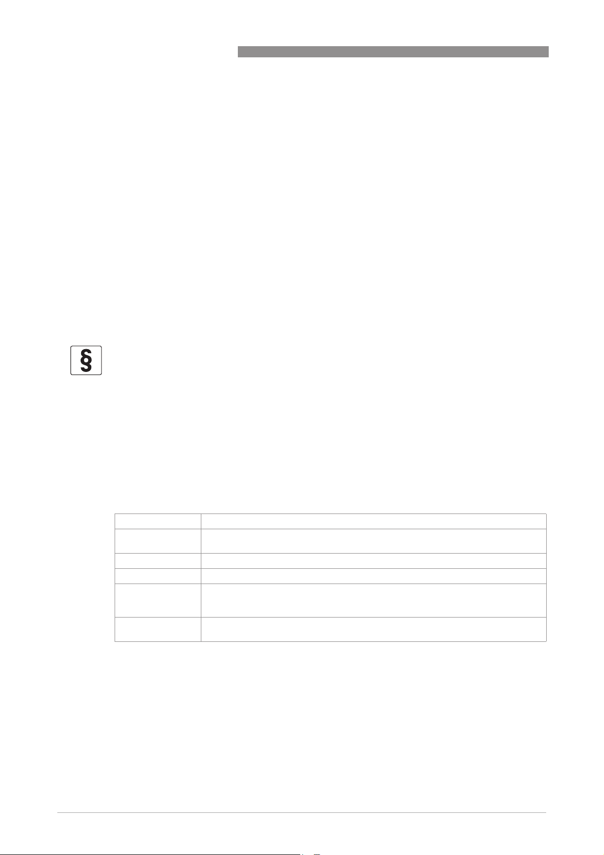
2.4 Nameplates
INFORMATION!
Look at the device nameplate to ensure that the device is delivered according to your order.
Check for the correct supply voltage printed on the nameplate.
DEVICE DESCRIPTION 2
Figure 2-5: Example of a ATEX nameplate
Figure 2-6: Example of a IECEx nameplate
www.krohne.com04/2013 - 4002643502 - MA ALTOSONIC V12 R02 en
15
Page 16
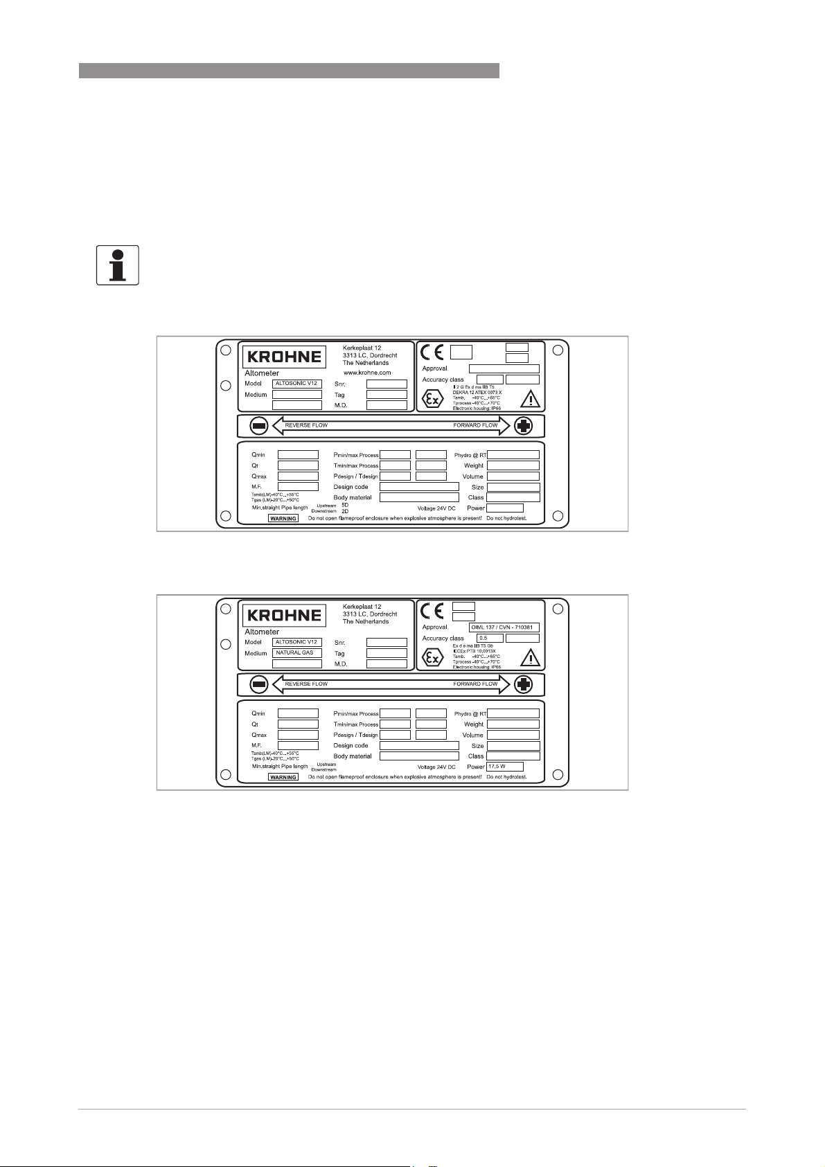
2 DEVICE DESCRIPTION
Figure 2-7: Example of a FM nameplate
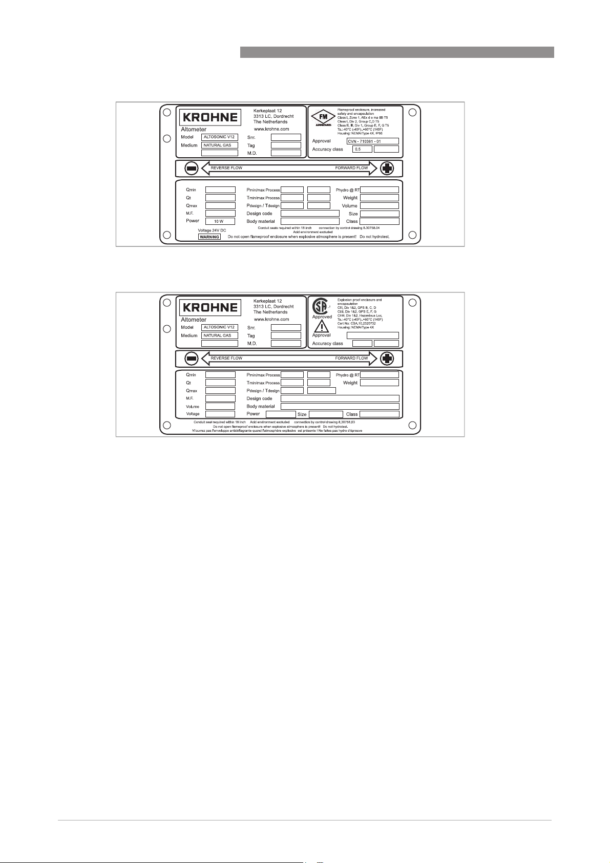
ALTOSONIC V12
Figure 2-8: Example of a CSA nameplate
16
www.krohne.com 04/2013 - 4002643502 - MA ALTOSONIC V12 R02 en
Page 17
ALTOSONIC V12
3.1 Notes on installation
CAUTION!
Inspect the packaging carefully for damages or signs of rough handling. Report damage to the
carrier and to the local office of the manufacturer.
INFORMATION!
Do a check of the packing list to make sure that you have all the elements given in the order.
INFORMATION!
Look at the device nameplate to ensure that the device is delivered according to your order.
Check for the correct supply voltage printed on the nameplate.
3.2 Storage
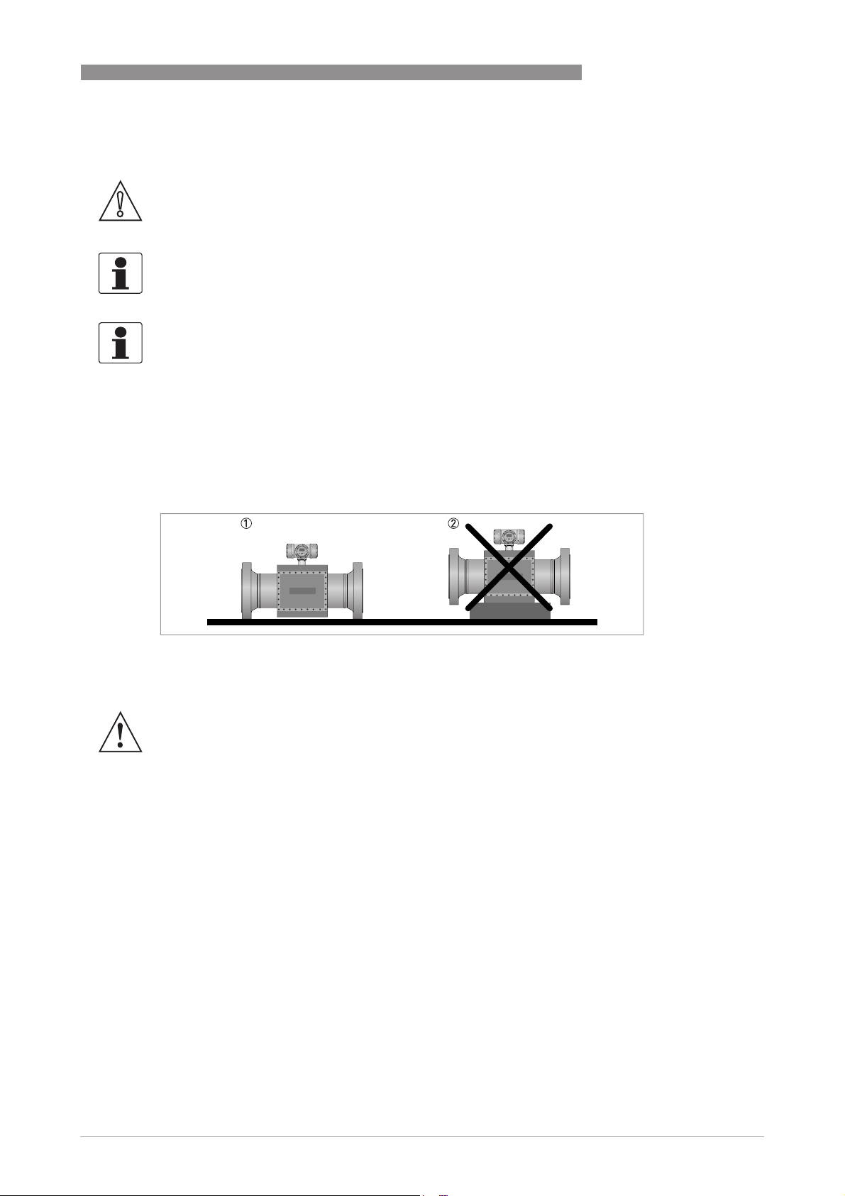
Correct storage position
INSTALLATION 3
Figure 3-1: Storage
1 Correct position for all sizes
2 Position not allowed for flowmeters > 12"
WARNING!
Make sure that the extensions on the bottom of the flanges are in good order to prevent the
meter from rolling over. Otherwise take appropriate measures to prevent the meter from rolling
over.
Storage conditions
Maintain the following storage conditions to prevent the equipment from corrosion or early
failure:
• Humidity: <95 % RH (closed and heated storage area)
• Storage temperature: -40...+65º C / -40...+149º F
• Avoid direct solar radiation during long storage periods, store under a sunshade
How to prevent corrosion
Pay attention to the conservation of the inner pipe wall, especially for carbon steel meters.
Typical applications such as measuring dry natural gas (sales quality) or natural gas with a
corrosion inhibitor do not require an anti corrosion coating inside the meter tube. A coating can
even be regarded as unwanted because it may wear off, which will have an impact (although
minor) on the accuracy.
www.krohne.com04/2013 - 4002643502 - MA ALTOSONIC V12 R02 en
17
Page 18

3 INSTALLATION
However for storage and/or transportation additional protective measures are recommended.
Depending on how long the protection should last one of several methods can be considered:
1. For a storage period of less than one year, the inner pipewall should be protected by a corrosion
inhibitor such as Shell Ensys.
Do not apply the corrosion inhibitor on the acoustic transducers.
2. For a period of a year or longer, the pipewall should be protected by Tectyl or a similar product.
Do not apply Tectyl on the acoustic transducers.
3. Independend of the storage period, the inner pipewall can be protected by an oxygen free envi-
ronment. This can be created by mounting blind flanges, using a vacuum pump to remove the
air and subsequently filling the meter with nitrogen. It is recommended to place some bags of
silica gel inside the flowmeter. To protect against corrosion, the humidity should be less than
38% and/or oxygen should not be present. Special regulations may be applicable for transportation and storage of a pressurised flowmeter.
3.3 Transport
WARNING!
•
Even smaller size flowmeters have a considerable weight. Check the weight of your
flowmeter in order to select suitable means for transportation and lifting.
•
Use appropriate materials such as chains or hoisting straps that are in good condition.
•
Use the eye bolts on the meter body to attach chains or straps to lift the meter (if not present:
check condition of the threaded holes on the flanges and if okay screw eye bolts in the
threaded holes).
•
Never lift the meter using the converter housing to attach straps.
•
In case a fork lift will be used make sure that the flowmeter is secured against rolling off the
forks, or against straps sliding off the forks.
•
Verify local safety regulations, directives and company procedures with respect to hoisting,
rigging and transportation of (heavy) equipment.
ALTOSONIC V12
18
www.krohne.com 04/2013 - 4002643502 - MA ALTOSONIC V12 R02 en
Page 19
ALTOSONIC V12
3.4 Pre-installation requirements
INFORMATION!
The equipment is designed for safe operation under conditions according to the following
classifications:
•
Pollution degree 2: this means that normally only nonconductive (dry) pollution will occur.
Temporary conductivity caused by condensation can occur.
•
Protection class I: this means the equipment must be earthed.
•
Humidity: <95% RH
•
Ambient temperature: -40...+65°C / -40...+149°F
•
Suitable for indoor and outdoor use.
•
IP66 / NEMA 4X classification.
CAUTION!
The flowmeter should be protected from corrosive chemicals or gases and dust or particles
accumulation.
CAUTION!
Do not intend to perform a hydrostatic test of the installed flowmeter.
INSTALLATION 3
The flowmeter has been hydrostatically tested during manufacturing (see reports) and must not
be retested with the ultrasonic sensors installed. Water will protude in the sensor pockets and
remain. This will create acoustic shortcuts and possibly cause the flowmeter to start operating
in failure.
3.5 Installation
3.5.1 Mounting position
Install the ultrasonic gas flowmeter in horizontal position with the flow arrow indicator on the
nameplate or on the meter body in the direction of the positive (forward) gas flow.
Make sure that the converter is on top of the flowmeter after the installation.
Check the weight of the meter. Typically the weight of the meter will be considerably more than
the same length of pipe line.
To support the meter additional supports might be needed, preferably two, one on either side of
the meter.
Always support the meter at its flanges, the weight of the meter shall never rest on the case
around the transducers and the cabling.
If supports can not be placed under the meter flanges, supports may be placed under the mating
flanges of the pipeline. If supports can only be placed under the pipeline sections upstream or
downstream of the meter, these supports shall be as close as possible to the meter. In this case
a calculation must be made to verify that the load on the pipeline will not exceed acceptable
values.
The meter should be installed in the pipe line with gaskets, nuts and bolts according to the type
and size of the flanges of the gas flowmeter. The flanges of the meter should match with the
flanges of the pipeline where the meter should be installed.
Make sure that the gaskets do not protude into the flow as this can reduce the accuracy of the
flowmeter.
www.krohne.com04/2013 - 4002643502 - MA ALTOSONIC V12 R02 en
19
Page 20
3 INSTALLATION
In order to install the gas flowmeter, the pipeline must have a slot of such length that the meter
including the gaskets fits nicely in the slot. It should not be necessary to use excessive force to
tighten the bolts in order to close the gaps on either side of the meter.
Nor should the slot be too small, implying the slot has to be widened by applying brute force to fit
the meter and gaskets in the slot.
For tightening the bolts of the flanges, apply a lubricant as required, in accordance with the
materials as used and applicable standards.
Tighten the bolts of the flanges with a torque according to the standards applicable to the
flanges and materials used.
3.5.2 Pipe diameters and lengths
Make sure that the inner diameter of upstream and downstream pipes matches the specified
connection diameter of the ultrasonic flowmeter within 1%. Contact KROHNE if the iner diameter
deviates more than 1%.
ALTOSONIC V12
3.5.3 Flow conditioners
Although the flowmeter is a highly accurate device, an additional flow conditioner can be
installed upstream of the flowmeter in order to minimize measuring uncertainty, in particular
when a strongly distorted flow velocity profile has to be expected, or when the available space for
a metering run is critical. If a flow conditioner is used the total inlet length may be reduced to
only 5 DN: having 2 DN upstream of the flow conditioner and 3 DN in between the flow
conditioner and the flowmeter.
INFORMATION!
•
Preferred model is the “perforated plate” type. A “pipe bundle” type of flow conditioner is not
recommended.
•
When a flow conditioner is included in the metering run, it is strongly advised to use the same
flow conditioner and inlet pipe configuration during a flow (wet) calibration (see e.g. ISO17089
or AGA-9 for detailed requirements).
3.5.4 Inlet and outlet for uni-directional use
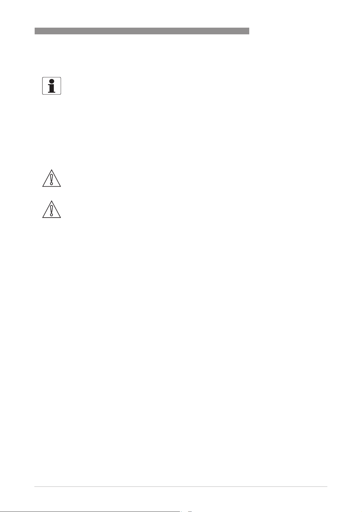
Without flow conditioner (OIML R137 class 0.5)
20
Figure 3-2: Reguired straight lengths for inlet and outlet
1 Inlet section: 10 DN
2 Outlet section: 3 DN
www.krohne.com 04/2013 - 4002643502 - MA ALTOSONIC V12 R02 en
Page 21
ALTOSONIC V12
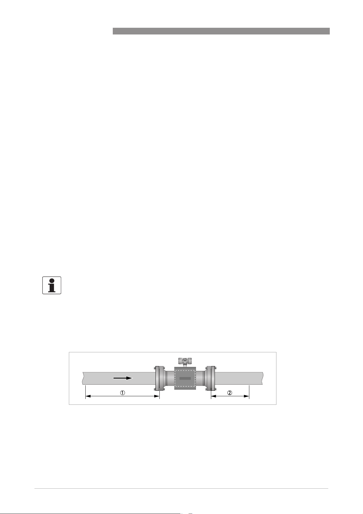
Without flow conditioner (AGA9, ISO 17089 and OIML R137 class 1)
Figure 3-3: Reguired straight lengths for inlet and outlet
1 Inlet section: 5 DN
2 Outlet section: 3 DN
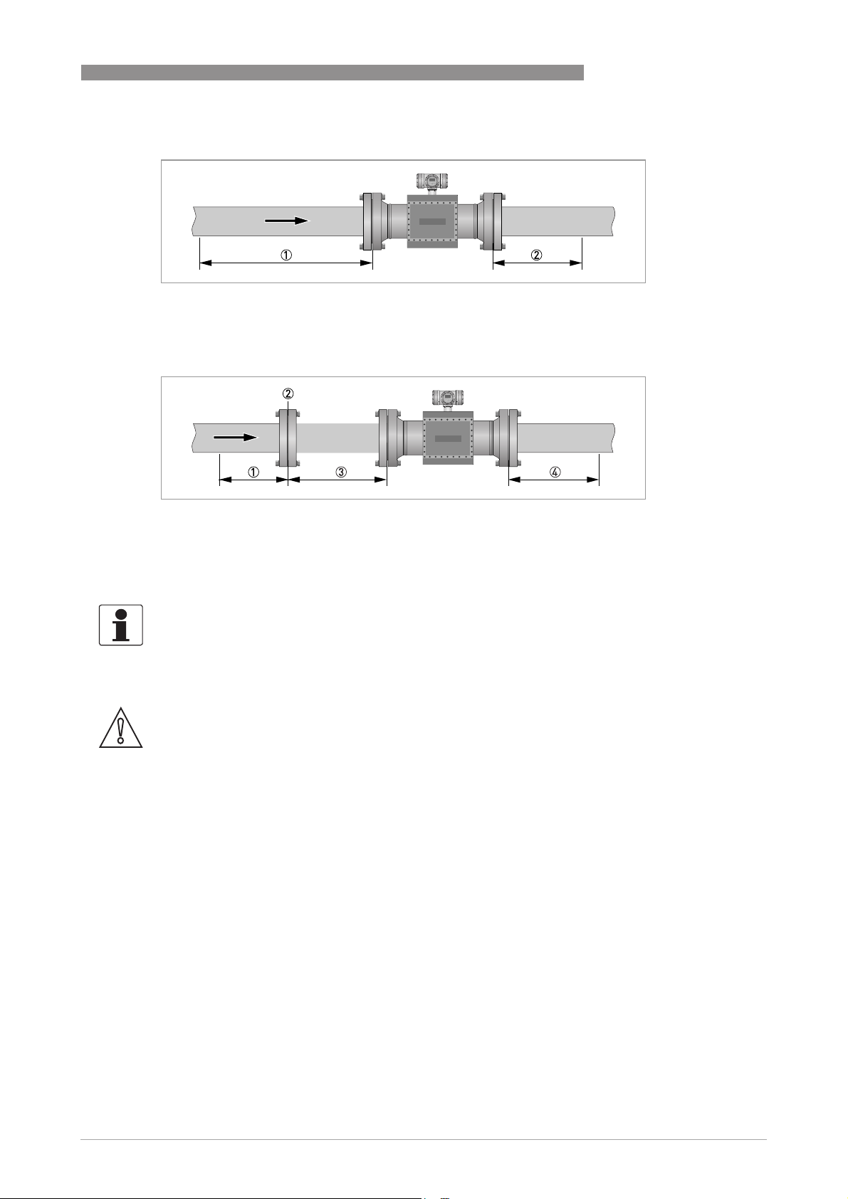
With flow conditioner
INSTALLATION 3
Figure 3-4: Reguired straight lengths for inlet and outlet
1 Inlet section before flow conditioner: 2 DN
2 Flow conditioner (perforated plate)
3 Inlet section after flow conditioner: 3 DN
4 Outlet section: 3 DN
INFORMATION!
Contact KROHNE for recommendations on bi-directional use.
3.5.5 Control valves
CAUTION!
Under circumstances ultrasonic gas flowmeters can suffer from interference from noise
generated by pressure control valves (PCV). In case the frequency spectrum of the PCV-noise
extends in the range of the operation frequency of the ultrasonic transducers and the strength of
the noise results in a signal to noise ratio smaller than the critical value, the ultrasonic
flowmeter will not be able to operate. Consult the manufacturer for advice in case a PCV with
high pressure cut will be operated close to the ultrasonic flowmeter.
www.krohne.com04/2013 - 4002643502 - MA ALTOSONIC V12 R02 en
21
Page 22
3 INSTALLATION
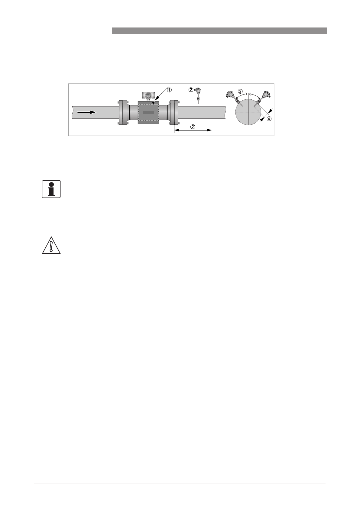
3.5.6 P and T sensors
Figure 3-5: Location of pressure and temperature transmitters
1 Install pressure transmitters on body of flowmeter at Pr point
2 Install temperature transmitter at 2...5 DN downstream of flowmeter
3 Install temperature transmitter under 45 degrees
4 Install temperature transmitter with an insertion depth between 0.1 and 0.33 of nominal pipe diameter.
INFORMATION!
•
See ISO 17089 for further details.
•
Use a PT 100 element with thermowell and transmitter as temperature transmitter.
Preferably use tapered thermowells to avoid vibrations.
•
Connect the pressure transmitter to the Pr-point in the meter body using an intermediate
isolation valve and/or valve manifold.
ALTOSONIC V12
CAUTION!
Either use a suitable blind plug or blind flange (and sealing as required) to blind the pressure
port, or a sense line should be connected in an appropriate way.
A sense line should be properly supported to avoid vibrations and to prevent the weight of the
sense line to apply a load on the connection at the pressure port.
22
www.krohne.com 04/2013 - 4002643502 - MA ALTOSONIC V12 R02 en
Page 23
ALTOSONIC V12
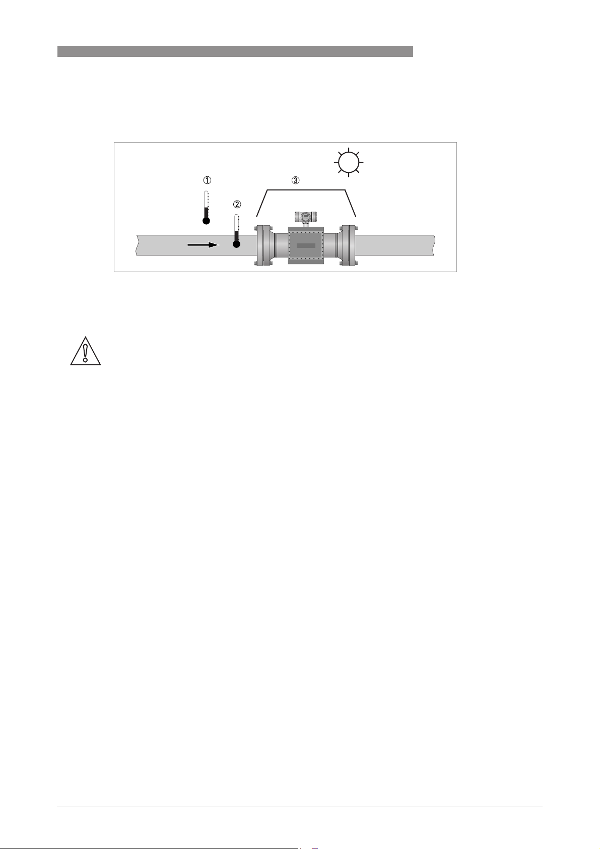
3.6 Temperatures
Figure 3-6: Temperatures
1 Ambient temperature
2 Process gas temperature
3 Use a sun shade to protect the flowmeter against direct solar radiation.
CAUTION!
SUNSHADE
SUNSHADE
SUNSHADESUNSHADE
Direct solar radiation introduces temperature gradients in the metering section and must be
avoided as much as possible. Use a sunshade or canopy over the flow, pressure and temperature
transmitters for protection against direct exposure to sunshine. Another option is to thermally
insulate the complete metering section including the transmitters.
INSTALLATION 3
For more detailed information about temperatures, refer to
Technical data table
on page 101.
www.krohne.com04/2013 - 4002643502 - MA ALTOSONIC V12 R02 en
23
Page 24
4 ELECTRICAL CONNECTIONS
4.1 Safety instructions
DANGER!
All work on the electrical connections may only be carried out with the power disconnected. Take
note of the voltage data on the nameplate!
DANGER!
Observe the national regulations for electrical installations!
WARNING!
Observe without fail the local occupational health and safety regulations. Any work done on the
electrical components of the measuring device may only be carried out by properly trained
specialists.
INFORMATION!
Look at the device nameplate to ensure that the device is delivered according to your order.
Check for the correct supply voltage printed on the nameplate.
ALTOSONIC V12
DANGER!
For FM installations, cables must be used that are resistant to high temperatures.
For all other applications, cable must be used that are resistant to high temperatures if the
°
process temperature is 65
C (149°F) or higher.
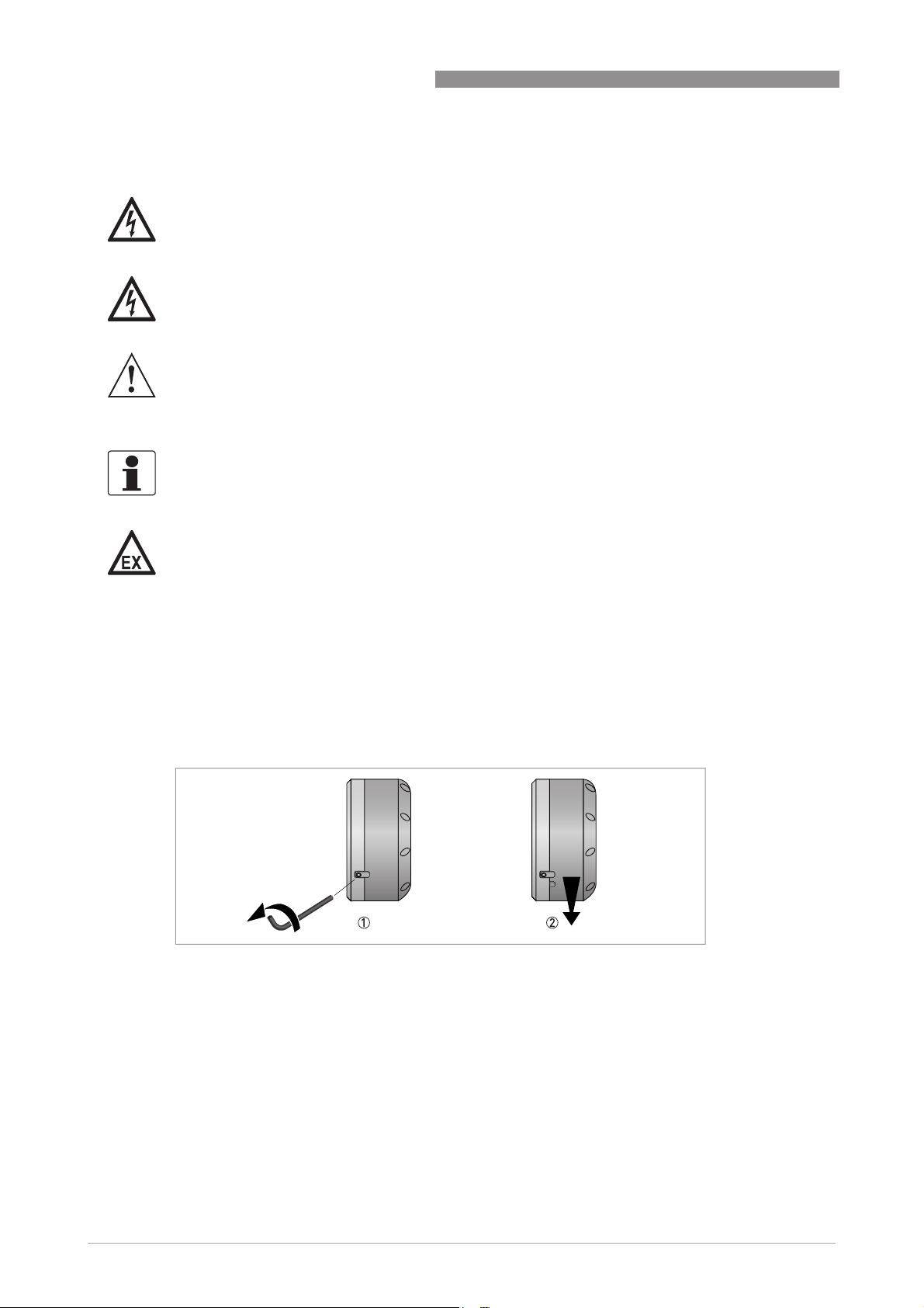
4.2 Opening and closing covers
All covers are equipped with an interlocking device to prevent unauthorized or inadvertent
opening and removal of the covers. Before a cover can be turned counter clockwise, the
interlocking device has to be released as shown in the figure below.
Figure 4-1: Opening cover with interlocking device
1 Loosen the hex screw with a 2.5 mm Allen key.
2 Turn the cover counter clockwise to open the cover.
24
Closing the covers is done in the reverse order. Turn the cover until the little know on the cover
is located under the interlocking device, then fasten the interlocking device.
www.krohne.com 04/2013 - 4002643502 - MA ALTOSONIC V12 R02 en
Page 25

ALTOSONIC V12
4.3 Digital I/O connections
WARNING!
1. In order to prevent unauthorized or inadvertent opening and removal of the covers, an inter-
locking device is provided for each cover. Before a cover can be rotated (counter clockwise) for
opening, release this interlocking device with a 2.5 mm Allen key.
2. The foot of the converter housing provide an earthing point, this must be connected to the near-
est safety earth conductor.
3. Only open the converter housing one minute after the power has been switched off and after it
has been verified that there is no risk due to the presence of potentially explosive gas.
• The digital outputs are passive open collector outputs, galvanically isolated from each other
and from the main circuit. To use these outputs an external voltage source and current
limiting resistors must be used. (NEC class 2 power supply (max. 100 VA, 24 VDC, IEC 610101, clause 6.3.1 and 6.3.2)
• For frequencies above 100 Hz, use shielded cables in order to reduce radiation from
electrical interferences (EMC).
• Terminal A+ is not used.
ELECTRICAL CONNECTIONS 4
Figure 4-2: Digital I/O as NPN transistor
www.krohne.com04/2013 - 4002643502 - MA ALTOSONIC V12 R02 en
25
Page 26
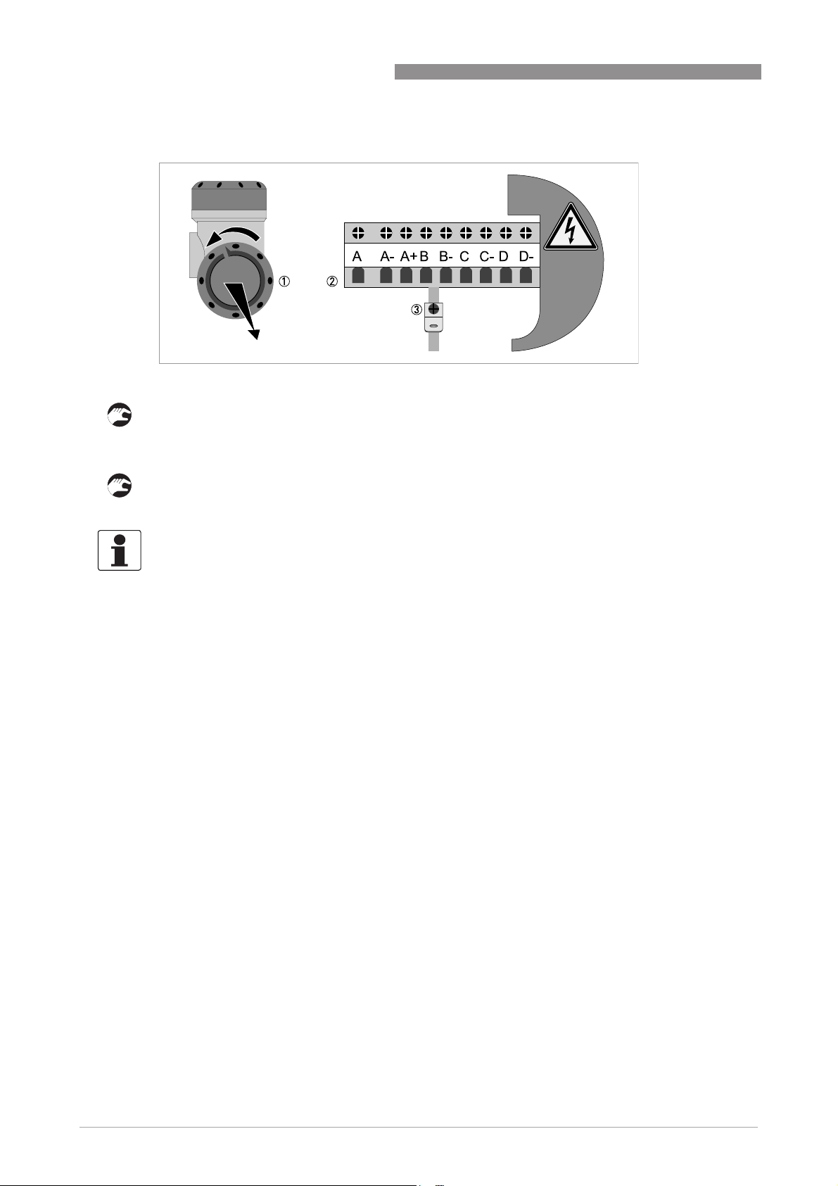
4 ELECTRICAL CONNECTIONS
Figure 4-3: Terminal compartment for inputs and outputs in field housing
1 Open the housing cover.
2 Push the prepared cable through the cable entry and connect the necessary conductors.
3 Connect the shield if necessary.
• Close the cover of the terminal compartment.
• Close the housing cover.
ALTOSONIC V12
INFORMATION!
Each time a housing cover is opened, the thread should be cleaned and greased. Use only resinfree and acid-free grease.
Ensure that the housing gasket is properly fitted, clean and undamaged.
4.3.1 Pulse and frequency output
Default the first digital I/O connection is set as a pulse/frequency output, having a frequency
proportional to the volume flow rate (actual volume: under process conditions). It is possible to
assign another variable to control this output (defined by means of parameter settings).
4.3.2 Status outputs
Default the next three digital I/O connections are defined as status outputs (Data not valid, Fail
unreliable and Reverse flow). However the function of these outputs can be programmed to
various alarms or status signals. One of the status outputs may be programmed to a second
pulse output, having the same frequency as the first pulse output, however the phase difference
can be set to either 0, 90, 180 or 270 degrees.
26
www.krohne.com 04/2013 - 4002643502 - MA ALTOSONIC V12 R02 en
Page 27
ALTOSONIC V12
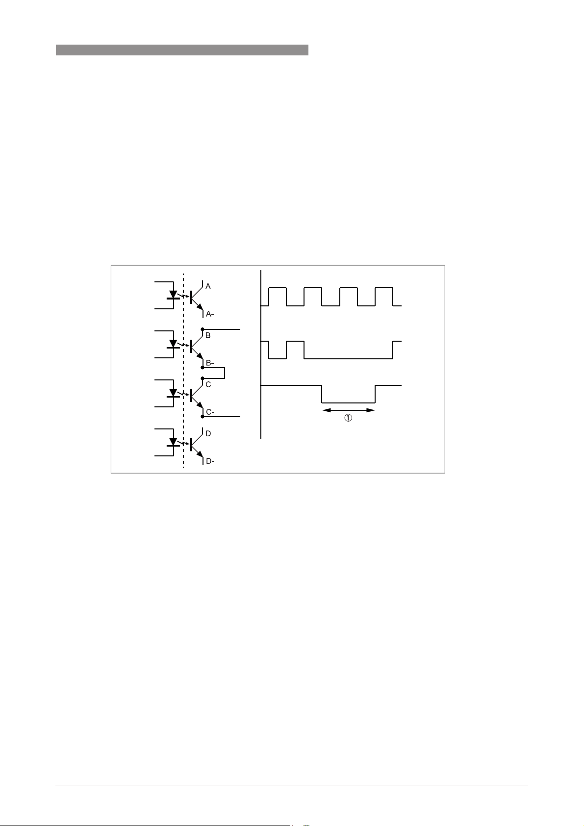
4.3.3 Emulation of a turbine meter
If the ultrasonic flowmeter should emulate a turbine meter, the following set up and settings can
be implemented:
• A/A-: Frequency output related to the line flow
• B/B-: Frequency output inverted related to the line flow whereby this frequency output will
stop operating if data valid alarm on status bit C/C- will occur.
Place the frequency output B/B in series with status bit C/C- as presented in the figure shown
below.
ELECTRICAL CONNECTIONS 4
Figure 4-4: Connection diagram for turbine emulation
1 Alarm
www.krohne.com04/2013 - 4002643502 - MA ALTOSONIC V12 R02 en
27
Page 28
4 ELECTRICAL CONNECTIONS
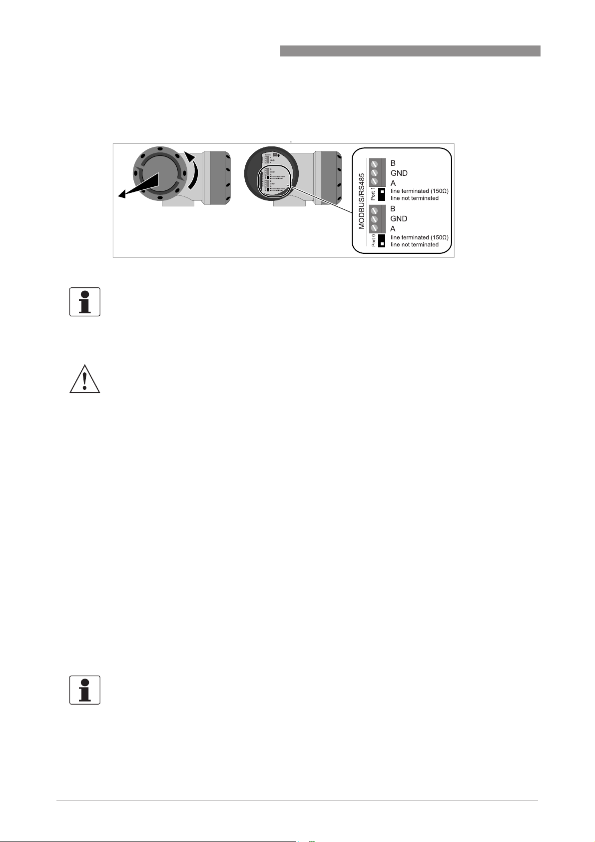
4.4 Serial data communication (RS 485)
Figure 4-5: Connection of serial data communication
INFORMATION!
For more information about Modbus, refer to Modbus protocol description and set-up on page
.
111
ALTOSONIC V12
4.5 Power connection
WARNING!
•
Use a 24 VDC power supply to power the flowmeter, which complies to NEC class 2 (max. 100
±
VA, 24 VDC
consumption is 17 W. The power supply must be able to supply 3 A (needed during start-up).
•
The protective earth conductor (1...4 mm2, AWG 17...AWG 11) of the power supply must be
connected to the protective conductor clamp terminal size M5, which is press-fitted in the
terminal compartment.
•
Use a cable entry to lead the power supply cable to the electronics. The power delivered from
the power converter inside the unit is limited to a maximum of 15 W according to the
”
principle (when the admissible internal power consumption is exceeded the delivered
back
power is reduced to zero). Separately the current consumption is limited to appr. 1A.
Requires typically 3 x 1.5 mm
•
Connection to a flow computer, a data acquisition system or process control system by
means of digital output signals; requires as a maximum 4 pairs of wires of 0.75 mm
18) copper each.
•
Connection by means of a RS 485 data line to a device for logging or monitoring data or
running a software service tool for performing a function check or a service jobs; requires a
shielded pair of two twisted conductors of 0.75 mm
•
Connection to a data acquisition system by means of digital signals; requires a shielded pair
of two twisted conductors of 0.75 mm
•
Connection to safety / protective ground (earthing) ; requires insulated wire, minimum copper
cross section area 4 mm
10% , see also IEC 61010-1, clause 6.3.1 and 6.3.2). The maximum power
2
(AWG 15) conductors.
2
(AWG 18) copper each.
2
(AWG 11).
2
(AWG 18) copper each.
“
fold-
2
(AWG
28
INFORMATION!
•
The protective conductor clamp or GND of the connector can be used for the shielding of the
cable.
•
The electronics is protected against connecting a power supply with the wrong polarity.
www.krohne.com 04/2013 - 4002643502 - MA ALTOSONIC V12 R02 en
Page 29
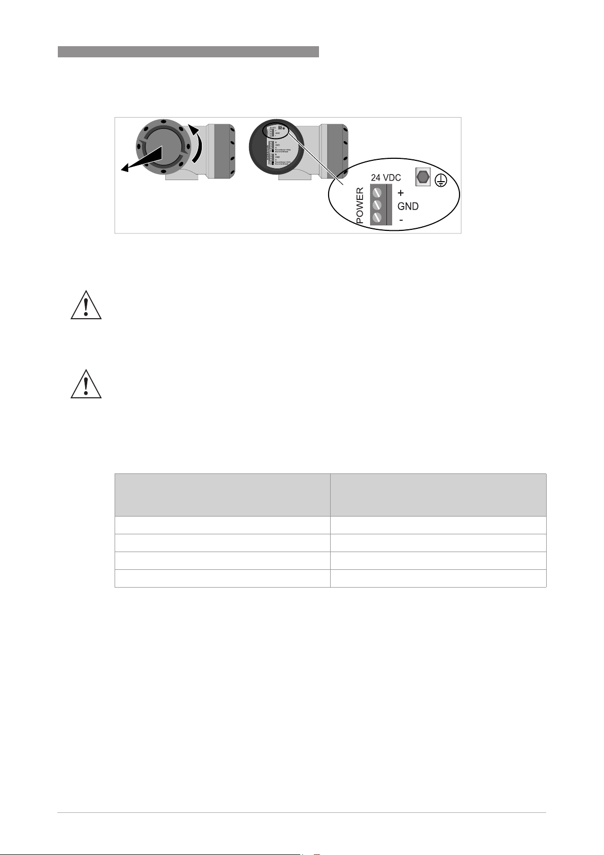
ALTOSONIC V12
Figure 4-6: Location of power connector
4.6 Cabling
WARNING!
•
•
ELECTRICAL CONNECTIONS 4
Replace any unused cable gland by an Ex-d blind plug!
The temperature rating of all cables must have a temperature rating of at least 65°C. In case
°
the process design temperature exceeds 65
least as high as the maximum process design temperature.
C, the cables must have a temperature rating at
WARNING!
In respect of the model of the cable glands used, the outer diameter of the cable must be
between 6.5 and 14 mm. Unused cable glands must be replaced by Ex d approved blind stops.
We recommend to use screened cable with twisted pairs for connecting power, serial outputs
and the status signals. The screen can be used to connect the ground terminal.
Length of power supply cable vs diameter
Length of cable between power supply and
flowmeter
[m]
70
100
200
400
Required minimum copper cross section
2 x 0.5 mm2 (AWG 20)
2 x 0.75 mm2 (AWG 18)
2 x 1.5 mm2 (AWG 15)
2 x 4 mm2 (AWG 11)
www.krohne.com04/2013 - 4002643502 - MA ALTOSONIC V12 R02 en
29
Page 30
4 ELECTRICAL CONNECTIONS
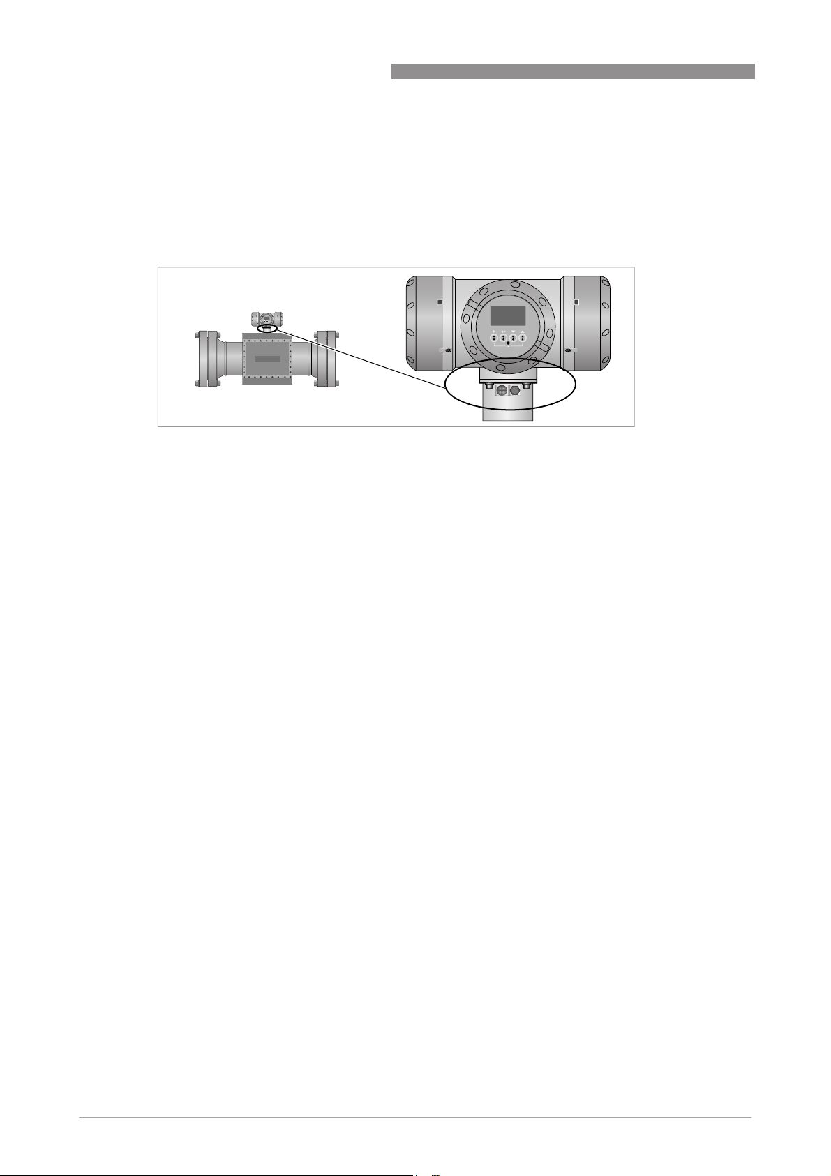
4.7 Grounding
There are two screw connection points (one M5 thread and one M4 thread) to attach a ground
conductor. They can be used to connect the upstream and downstream piping to the flowmeter
(Equipotential).
Figure 4-7: Location of grounding connectors
ALTOSONIC V12
30
www.krohne.com 04/2013 - 4002643502 - MA ALTOSONIC V12 R02 en
Page 31

ALTOSONIC V12
5.1 Starting the signal converter
The measuring device, consisting of the measuring sensor and the signal converter, is supplied
ready for operation. All operating data have been set at the factory in accordance with your order
specifications.
CAUTION!
The used power supply must be able to supply at least 3 A during the start-up of the converter.
When the power is switched on, a self test is carried out (KROHNE logo is visible during the test).
After that the device immediately begins measuring, and the current values are displayed.
START-UP 5
Figure 5-1: Displays in measuring mode (examples for 2 or 3 measured values)
x, y and z denote the units of the measured values displayed
It is possible to change between the two measured value windows, the trend display and the list
with the status messages by pressing the keys ↑ and ↓.
www.krohne.com04/2013 - 4002643502 - MA ALTOSONIC V12 R02 en
31
Page 32

6 OPERATION
6.1 Display and operating elements
Figure 6-1: Display and operating elements (Example: flow indication with 2 measuring values)
1 Indicates a possible status message in the status list
2 Field with product name, indication whether CT parameters have been locked (closed lock symbol) and the page num-
ber that is shown on the display
3 Indicates when a key has been pressed
4 1st measured variable in large representation
5 Keys (see table below for function and representation in text)
6 Interface to the GDC bus (not present in all signal converter versions)
7 Infrared sensor (not present in all signal converter versions)
ALTOSONIC V12
INFORMATION!
•
The switching point for the 4 optical keys is located directly in front of the glass. It is
recommended to activate the keys at right angles to the front. Touching them from the side
can cause incorrect operation.
•
After 5 minutes of inactivity, there is an automatic return to measuring mode. Previously
changed data is not saved.
32
www.krohne.com 04/2013 - 4002643502 - MA ALTOSONIC V12 R02 en
Page 33

ALTOSONIC V12
OPERATION 6
Key Measuring mode Menu mode Submenu or function
mode
> Switch from measuring
mode to menu mode;
press key for 2.5 s
^ Reset of display Return to measuring
or Switch between the five
screens: M1, M2, G1, S0,
Version and modbus
settings.
Esc (> + ↑) - - Return to menu mode
Table 6-1: Description of key functionality
Access to displayed
menu, then 1st
submenu is displayed
mode but prompt
whether the data should
be saved
Select menu Select submenu or
Access to displayed
submenu or function
Press 1 to 3 times,
return to menu mode,
data saved
function
without acceptance of
data
6.1.1 Display in measuring mode with 2 or 3 measured values
Parameter and data
mode
For numerical values,
move cursor
(highlighted in blue) one
position to the right
Return to submenu or
function, data saved
Use cursor highlighted
in blue to change
number, unit, setting
and to move the decimal
point
Return to submenu or
function without
acceptance of data
Figure 6-2: Example for display in measuring mode with 2 or 3 measured values
1 Indicates a possible status message in the status list
2 Lock, indicating that programming is not possible
3 Actual screen
4 First measured variable in large depiction
5 Depiction with 3 measured values
www.krohne.com04/2013 - 4002643502 - MA ALTOSONIC V12 R02 en
33
Page 34

6 OPERATION
6.2 Menu overview
ALTOSONIC V12
Menu
Description
number
4.1.2 Settings
4.1.2.1 Language
4.1.2.2 Default Page
4.1.2.3 Bargraph Labrl
4.1.3 Measurement Page 1
4.1.3.1 Number of lines
4.1.3.2 Line Settings 1
4.1.3.3 Line Settings 2
4.1.3.4 Line Settings 3
4.1.4 Measurement Page 2
4.1.4.1 Number of lines
4.1.4.2 Line Settings 1
4.1.4.3 Line Settings 2
4.1.4.4 Line Settings 3
4.1.5 Graphical Page
4.1.5.1 Show Value
4.1.5.2 Graph type
4.1.5.3 Minimum
4.1.5.4 Maximum
4.1.5.5 Time
Settings
SettingsSettings
Measurement Page 1
Measurement Page 1Measurement Page 1
Measurement Page 2
Measurement Page 2Measurement Page 2
Graphical Page
Graphical PageGraphical Page
34
4.1.6 Status Page
4.1.6.1 Reset Errors
Status Page
Status PageStatus Page
www.krohne.com 04/2013 - 4002643502 - MA ALTOSONIC V12 R02 en
Page 35

ALTOSONIC V12
6.3 Access control and seals
All acoustic transducers and the electronics unit of ALTOSONIC V12 can be exchanged without
the need for recalibration. The only exception is the board that holds all Custody Transfer (CT)
settings. After initial calibration of the ALTOSONIC V12 all CT settings are stored inside the
meter and a dipswitch no 4 is put in the locked position. The dipswitches are subsequently
sealed by the calibration facility, guaranteeing no un-authorised changes can be made to the
meter. Contact KROHNE in case the board with the sealed dipswitches needs to be replaced.
OPERATION 6
Figure 6-3: Location of DIP switch for sealing
1 Turn cover counter clockwise and remove the cover.
2 Pull the metal grips to remove the display.
3 Remove the plastic cover with a screwdriver.
4 Locate the DIP switch number 4:
ON = free
OFF = locked.
CAUTION!
The CT approval is no longer valid if the dipswitch number 4 is switched to ON!
The cover of the electronics can be sealed too (optionally).
Figure 6-4: Optional sealing of cover
www.krohne.com04/2013 - 4002643502 - MA ALTOSONIC V12 R02 en
35
Page 36

6 OPERATION
INFORMATION!
The sealing of the cover is not required and can be broken without affecting the CT approval.
The nameplate must be sealed to the flowmeter, as shown in the figure below. Alternatively the
nameplate can be welded on the flowmeter or be mounted with rivets, so that removal without
destroying the name plate is not possible.
ALTOSONIC V12
Figure 6-5: Sealing of nameplate
36
www.krohne.com 04/2013 - 4002643502 - MA ALTOSONIC V12 R02 en
Page 37

ALTOSONIC V12
7.1 Introduction
The KROHNE Flowmeter Configuration and Monitoring Tool is a software package to support the
application of the ALTOSONIC V12 ultrasonic gas flowmeters. It is designed to be used with a PC
with a Windows operating system and can be downloaded from www.krohne.com.
It can:
• collect data from a flowmeter
• present data from a flowmeter
• verify / set / adjust parameters used by the software inside the flowmeter.
The software can be operated using different communication methods such as:
• TCP/IP
• Modbus
• USB
7.2 Installation of the software
SOFTWARE SERVICE TOOL 7
After the software has been installed properly, the Windows Program menu will have an item
KROHNE Custody Transfer Products with sub item KROHNE Flow Meter Configuration &
Monitoring Tool.
7.3 Starting a session
CAUTION!
To secure reliable operation of the meter, access is limited by means of passwords. Different
levels of passwords are available for staff with the proper skills and authorization to allow them
to perform the jobs they are entitled to.
INFORMATION!
A session is the activity starting with establishing communication (connecting) with a meter. A
session ends when the communication process with a meter is terminated (disconnecting).
During a session data can be collected from a meter in order to monitor and evaluate the
performance, the collected data may be stored as a log file and parameters can be adjusted.
After the program is launched a blank screen will appear with only a number of menu pull down
buttons on the menu bar on the upper left side of the computer screen.
Figure 7-1: Start-up screen, upper part
The lower left corner of the screen shows a status bar with some information fields and status
fields or status indicators.
www.krohne.com04/2013 - 4002643502 - MA ALTOSONIC V12 R02 en
37
Page 38

7 SOFTWARE SERVICE TOOL
Figure 7-2: Start-up screen, lower part
The first field is an information field, reserved to show the communication method in operation.
Without an active communication the first and the second fields will show a dash.
When communication with a flowmeter has been established, the second field will show the
address of this flowmeter, valid for the communication method in operation.
ALTOSONIC V12
Figure 7-3: Connect the device
1. Choose and click the menu pull down button Device.
A menu will open with the options Connect, Reconnect and Disconnect.
2. Click Connect (at this time the only valid option).
This will open a dialog box asking to select or confirm the communication method you intend to
use.
Figure 7-4: Communication interfaces
38
1. Click OK to confirm if you want to select the option as displayed or - if not -
2. Click the down button to have the other options displayed.
3. Select and click the option you need.
4. Click OK to confirm.
www.krohne.com 04/2013 - 4002643502 - MA ALTOSONIC V12 R02 en
Page 39

ALTOSONIC V12
KROHNE Flowmeter Configuration and Monitoring Tool will now send a message, asking for a
response from any meter that is able to communicate using the selected communication
method.
SOFTWARE SERVICE TOOL 7
Figure 7-5: Settings for Modbus port 0
www.krohne.com04/2013 - 4002643502 - MA ALTOSONIC V12 R02 en
39
Page 40

7 SOFTWARE SERVICE TOOL
ALTOSONIC V12
Figure 7-6: Settings for Modbus port1
When using TCP/IP (network environment) a dialog box will appear listing the responding
meters. If multiple instruments are present in the same network a list will be presented.
The other communication option are peer-to-peer and will request for setting up the
communication link.
An arrow in the most left column in the dialog box marks the meter selected to start a
communication session.
40
www.krohne.com 04/2013 - 4002643502 - MA ALTOSONIC V12 R02 en
Page 41

ALTOSONIC V12
Figure 7-7: Select the device
1. To confirm the selection, click on the arrow in the most left field of the row with the meter se-
lected by default.
2. To select another meter: move the arrow to the row with the meter you want to communicatie
with, click in the most left field of the row showing the meter.
3. Confirm your choice by clicking OK.
SOFTWARE SERVICE TOOL 7
In case that you do not get a response from any meter or you don’t get a response from the
meter you want to communicate with. Reasons can be:
• there is no ultrasonic flowmeter operational, or
• the meter you want to communicate with is not connected to a power source, or
• the communication line is not properly connected.
If this happens you can press the button “Rescan” after the problem is solved. MCST will now
resend the message, asking for a response from any meter that is able to communicate using
the selected communication method. If the problem has been solved properly, the meter that
you are looking for will be listed in the dialog box.
You have now selected a communication method and a meter. The selected communication
method and flowmeter address will now appear in the respective information fields in the status
bar at the bottom of the screen.
Figure 7-8: Selection at the bottom of the screen
Type your name and password in the dialog box and click OK.
www.krohne.com04/2013 - 4002643502 - MA ALTOSONIC V12 R02 en
41
Page 42

7 SOFTWARE SERVICE TOOL
Figure 7-9: Login dialog box
Standard: User: operator / Password: operator
or User: supervisor / Password: supervisor
ALTOSONIC V12
The selected communication method and flowmeter address will appear in the respective
information fields in the status bar at the bottom of the screen.
Figure 7-10: Status bar information
7.4 Loading a monitoring configuration
INFORMATION!
There are two different methods to obtain data from a flowmeter.
•
Request information on a specific data item: if it is a parameter the current value will be
reported, this is a static value. If it is a variable, the value will be reported and updated every 2
seconds.
•
Define a selection of data that the flowmeter will send as a package and update at specific
rate. This way the data collecting process is customized to collect only those variables or data
elements that one really needs or wants to be monitored and / or logged (as the meter
produces a large amount of data it will not be possible to collect and update all the variables
in a short time interval).
“
The option
flowmeter at a specific update rate. This option is used to define the set of data that will be
collected from the flowmeter: this set of data will be available to be displayed simultaneously.
The specification of such a set of data is stored in a monitoring configuration file, a file with an
extension
installation package. Once a monitoring configuration is loaded, the monitoring process can be
started and stopped.
Configure” is available to customize the selection of data to be sent from the
“
.mon ” . A default monitoring configuration file can be found in the software
42
To load a monitoring configuration:
www.krohne.com 04/2013 - 4002643502 - MA ALTOSONIC V12 R02 en
Page 43

ALTOSONIC V12
Step 1:
Step 1: Click the button “File” to open the File menu.
Step 1:Step 1:
Step 2:
Step 2: Select the option “Open Monitoring Configuration”.
Step 2:Step 2:
Figure 7-11: File menu
SOFTWARE SERVICE TOOL 7
A browser window will open.
Figure 7-12: Open monitoring configuration
Step 3:
Step 3: Select a monitoring configuration file and click “Open”.
Step 3:Step 3:
INFORMATION!
You can create and save one or more monitoring configurations of your own, according to your
own preferences. Later it will be explained how you can do this.
As a start you can select the default monitoring configuration file.
A dialog box will appear, asking whether you want to start the monitoring function now:
Step 4:
Step 4: Click “Yes” to start the monitoring function.
Step 4:Step 4:
www.krohne.com04/2013 - 4002643502 - MA ALTOSONIC V12 R02 en
43
Page 44

7 SOFTWARE SERVICE TOOL
The monitoring status field updates from “Mon.OFF” to “Mon.ON”, and turns from yellow into
green.
Figure 7-13: Green status field
Alternatively you can configure the software to automatically find a monitoring configuration file
and start monitoring immediately after the program is launched.
Step 5:
Step 5: Click the “Tools” button to open the tools menu.
Step 5:Step 5:
ALTOSONIC V12
Figure 7-14: Tools menu
Step 6:
Step 6: Click “Settings”. A window “Settings” with 4 tabbed sheets will open.
Step 6:Step 6:
44
Figure 7-15: Settings
Step 7:
Step 7: On the sheet ”Auto start” select the box “Start monitoring after connecting”.
Step 7:Step 7:
www.krohne.com 04/2013 - 4002643502 - MA ALTOSONIC V12 R02 en
Page 45

ALTOSONIC V12
Step 8:
Step 8: You can:
Step 8:Step 8:
• click the button “Use current configuration”, or
• click “Browse” to open another window This is an identical browse window as used before to
Step 9:
Step 9: Click “OK” to confirm the settings.
Step 9:Step 9:
The next time you launch the program the steps 1...4 will be skipped.
find a monitoring configuration file.
Select the file you want to use to start monitoring the next time you connect to a meter.
SOFTWARE SERVICE TOOL 7
7.5 Changing and saving a monitoring configuration
7.5.1 Creating a monitoring configuration
When opening the KROHNE Flowmeter Configuration and Monitoring Tool the default settings
are such that a default monitoring file is loaded and that a default user view is activated. Also the
KROHNE Flowmeter Configuration and Monitoring Tool will start logging directly. All these
features will be discussed in the next paragraphs. If due to unforeseen reasons the default start
up settings does not start up in the paragraphs below the different steps are discussed to
activate monitoring, user view and logging.
In order to modify the selection of data available for monitoring, change the monitoring
configuration.
Step 1:
Step 1: Click the button “Monitoring” to open the monitoring menu.
Step 1:Step 1:
Figure 7-16: Monitoring menu
Step 2:
Step 2: Click the option “Configure…”.
Step 2:Step 2:
In case a monitoring session is active the message box as below will appear.
Figure 7-17: Warning for running session
www.krohne.com04/2013 - 4002643502 - MA ALTOSONIC V12 R02 en
45
Page 46

7 SOFTWARE SERVICE TOOL
Step 3:
Step 3: Click “Yes” to stop the monitoring activity.
Step 3:Step 3:
INFORMATION!
Note that the instrument itself will not stop measuring! Only the presentation of measuring
results will be interrupted.
The Monitoring Configuration dialog appears:
ALTOSONIC V12
Figure 7-18: Monitoring configuration
Step 4:
Step 4: Click “Edit List” . The Monitoring List editor dialog appears:
Step 4:Step 4:
Figure 7-19: Monitoring list
46
www.krohne.com 04/2013 - 4002643502 - MA ALTOSONIC V12 R02 en
Page 47

ALTOSONIC V12
Variables can be added to the list of values to be collected from the meter and become available
for presentation:
Step 5:
Step 5: Open the tree structure in the left panel, and select the variable name to be added to the
Step 5:Step 5:
list.
Step 6:
Step 6: Click the button pointing to the right in the center panel. The item will now appear in the
Step 6:Step 6:
list in the right panel.
Similarly variables can be deleted from the list of values to be collected from the meter, these
values will no longer be available for monitoring / logging.
Step 7:
Step 7: In the right panel, click in the box to the left of the name/description of the variable to be
Step 7:Step 7:
deleted, the pointer will not move to this line. This will also enable the button in the center panel
with the arrow pointing to the left.
Step 8:
Step 8: Click on this button to remove the selected item from the list.
Step 8:Step 8:
Step 9:
Step 9: Click the button in the centre panel with the double arrow to the left to clear the list
Step 9:Step 9:
completely.
SOFTWARE SERVICE TOOL 7
Step 10:
Step 10: Click the button “Close” in the centre panel to finish this part: Monitoring List editor
Step 10:Step 10:
screen will disappear, Returning to the “Monitoring Configuration Window”.
You can adjust the rate at which the selected data will be sent and updated:
Step 11:
Step 11: Click the “down”- arrow left of “Interval in sec.”
Step 11:Step 11:
Step 12:
Step 12: Click on the rate according to your preference.
Step 12:Step 12:
Figure 7-20: Monitoring configuration
Step 13:
Step 13: Click the “Close” button in the lower right corner of this window to finish this part. A
Step 13:Step 13:
dialog box will ask if you want to (re)start the monitoring process.
www.krohne.com04/2013 - 4002643502 - MA ALTOSONIC V12 R02 en
47
Page 48

7 SOFTWARE SERVICE TOOL
Figure 7-21: Restart of monitoring
Step 14:
Step 14: Click “Yes” to resume the monitoring process.
Step 14:Step 14:
7.5.2 Saving a monitoring configuration with a new name
INFORMATION!
•
If you want to save both the modified monitoring configuration as well as the monitoring
configuration you used as a starting point, you will need to save now the modified
configuration (with a new unique name).
•
If you do not save the modified configuration now, the program will prompt you at the time
you close the program, however at that time you have only two options: you can save the
configuration used as a starting point (loosing your modifications) or you can save the
modified configuration, this will overwrite the starting configuration (and the starting
configuration will be lost).
ALTOSONIC V12
Step 1:
Step 1: Click the button "File" to open the file menu.
Step 1:Step 1:
Figure 7-22: File menu
Step 2:
Step 2: Click the menu item “Save Monitoring Configuration As..”.
Step 2:Step 2:
48
www.krohne.com 04/2013 - 4002643502 - MA ALTOSONIC V12 R02 en
Page 49

ALTOSONIC V12
Figure 7-23: Save monitoring configuration
SOFTWARE SERVICE TOOL 7
Step 3:
Step 3: Type a new name in the box “Filename”.
Step 3:Step 3:
Step 4:
Step 4: Click "Save".
Step 4:Step 4:
Your new monitoring configuration is now saved with its new name.
7.5.3 Saving a monitoring configuration with its current name
You can save an updated version of your monitoring configuration at any time:
Step 1:
Step 1: Click the "File" button to open the file menu.
Step 1:Step 1:
Figure 7-24: File menu
Step 2:
Step 2: Click “Save Monitoring Configuration”.
Step 2:Step 2:
The monitoring configuration file used as starting point will now be replaced by the modified
monitoring configuration.
www.krohne.com04/2013 - 4002643502 - MA ALTOSONIC V12 R02 en
49
Page 50

7 SOFTWARE SERVICE TOOL
7.6 Creating a monitoring configuration
CAUTION!
If you have no monitoring configuration file available to start with, or when you have not yet
opened a monitoring configuration file, the option
available.
You have to use the option “New Monitoring Configuration…” in the File menu to create a
monitoring configuration file.
Step 1:
Step 1: Click the “File” menu button.
Step 1:Step 1:
ALTOSONIC V12
“
Configure…” in the “Monitoring” menu is not
Figure 7-25: File menu
Step 2:
Step 2: Click the option “New Monitoring Configuration…”.
Step 2:Step 2:
You can use this even if you already have a monitoring configuration opened and running. In that
case you are asked to stop the running monitoring session.
Figure 7-26: Warning for running session
Click “Yes”.
Now the Monitoring Configuration screen appears:
50
www.krohne.com 04/2013 - 4002643502 - MA ALTOSONIC V12 R02 en
Page 51

ALTOSONIC V12
SOFTWARE SERVICE TOOL 7
Figure 7-27: Monitoring configuration
Step 3:
Step 3: Click “Edit List”.
Step 3:Step 3:
The empty Monitoring List Editor window will appear.
Figure 7-28: Monitoring list editor
Step 4:
Step 4: Open the tree in the panel to the left of the window, select the data items you want to
Step 4:Step 4:
monitor and add these to the list in the panel to the right of the window, by pressing the ">"
button.
Step 5:
Step 5: When finished, click “Close” in the “Monitoring List Editor” window.
Step 5:Step 5:
Step 6:
Step 6: Set or adjust the “Fetch Rate” to the value as required.
Step 6:Step 6:
www.krohne.com04/2013 - 4002643502 - MA ALTOSONIC V12 R02 en
51
Page 52

7 SOFTWARE SERVICE TOOL
Step 7:
Step 7: Click “Close” in the “Monitoring Configuration” window.
Step 7:Step 7:
The “Monitoring” window reappears:
Figure 7-29: Start monitoring?
Step 8:
Step 8: Click “Yes” to start the monitoring process.
Step 8:Step 8:
ALTOSONIC V12
Store the new monitoring configuration using the “Save…” option in the File menu as described
before. Assign a name to the new monitoring configuration: the “Save Monitoring Configuration”
screen will appear.
If you create a new monitoring configuration while an existing monitoring configuration is open:
at the time you exit the program, you are asked to replace the starting configuration, or you may
decide not (if you want to keep both you have to use the “Save as…” option before you exit the
program).
7.7 Viewing data
The easiest way to view data is to open a predefined User Views menu.
52
Figure 7-30: View menu
1. Click the button View on the menu bar to open the View menu.
2. Click the option User Views to open the User Views window.
www.krohne.com 04/2013 - 4002643502 - MA ALTOSONIC V12 R02 en
Page 53

ALTOSONIC V12
This window may contain multiple sheets or tabs. Each tab represents a sheet displaying a selection of data, in numerical or graphical format (or both).
More sheets may be present allowing to present different sets of data or to present data in different formats. A particular sheet is identified by means of its name as is shown on its Tab.
3. In the window User Views, any sheet may be selected by clicking on its associated Tab.
4. Other windows may be selected to be viewed using the View menu.
7.7.1 Unformatted data
Step 1:
Step 1: Click the button “View” on the menu bar to open the “View menu”.
Step 1:Step 1:
Step 2:
Step 2: Click “Monitoring Data (unformatted)…”.
Step 2:Step 2:
An information window as below will appear as a scroll list.
SOFTWARE SERVICE TOOL 7
Figure 7-31: Unformatted data
The shown data is the data as currently being collected from the meter: only the values of the
variables as defined in the monitoring configuration file.
www.krohne.com04/2013 - 4002643502 - MA ALTOSONIC V12 R02 en
53
Page 54

7 SOFTWARE SERVICE TOOL
7.8 Customizing the way data is presented
The data presented in “User Views” can be configured according to your speciific needs or
preferences. This applies to the selection of the data and to the way the data is presented: in
numerical format or as a graph.
INFORMATION!
Only data that is actually gathered from the flowmeter (as set up in the Monitoring
Configuration), is available to be displayed. A data item not included in the
available to be displayed. You have to use the option
“
to the
7.8.1 Setting up tabs in the user view window
The window “User Views” has two buttons in its lower right corner: “Add Tab” and “Remove Tab”.
Removing a tab
Removing a tab
Removing a tabRemoving a tab
Use the button “Remove Tab” to remove an existing sheet in the window “User Views”. In case the
“User Views” window has multiple sheets, the currently opened sheet will be deleted.
Fetch list” any data item you want to see in order to make it available for presentation.
ALTOSONIC V12
“
Fetch list” will not be
“
Configure” in the “Monitoring” menu to add
INFORMATION!
in case you made a change, you will be reminded that you changed the monitoring configuration
file when you close MCST. If you accept the modified configuration file to be saved, you will not be
able to recover the deleted sheet the next time you start MCST.
If you want to keep both the set up you started with and the modified version, save the new
version with a new name before closing the program. Use the command “Save Monitoring
Configuration As..” (in File Menu) . This command stores the set up of the information sheets
contained in “User Views” as well.
Adding / creating a tab
Adding / creating a tab
Adding / creating a tabAdding / creating a tab
Using the button “Add Tab” you can add a new (empty) sheet in the window “User Views” and
create a sheet to your own preferences.
A sheet can be set up as one single panel, or split in two sections, arranged as an upper panel
and a lower panel. Each panel can be used to display data either as a graph or as numerical
values displayed in cells arranged in a grid.
INFORMATION!
“
The format of the way data is presented in a panel is stored in a file with an extension
“
presenting data as numerical values),
“
trend on a time axis) or
.xygx” (for presenting data as a graph of one variable as a function of
.trdx” (for presenting data as a graph, showing values as a
.grdx” (for
another variable).
54
The name of the file defining the format of the presentation in a specific panel can be read in its
upper left corner.
www.krohne.com 04/2013 - 4002643502 - MA ALTOSONIC V12 R02 en
Page 55

ALTOSONIC V12
CAUTION!
The files used for the preset
your own
according to your preference.
In case you use an existing
only a half sized upper or lower panel) to fill a sheet or tab with only one panel, it will
automatically expand to fill the whole of the panel.
To add/create a new tab:
Step 1:
Step 1: Click the “Add Tab” button.
Step 1:Step 1:
Step 2:
Step 2: The “Add Tab” dialogue appears prompting you to enter a name for the sheet and to
Step 2:Step 2:
define the data format (graph or numerical) to be used in the upper panel and the lower panel (in
case only one panel is defined the sheet will have just one panel).
SOFTWARE SERVICE TOOL 7
“
User Views” tabs can be reused. This is the easiest way to create
“
sheets” or “tabs” : making combinations of the predefined grids and/or graphs
–
predefined- format (even if it appeared before as a format filling
Figure 7-32: Add tab
Step 3:
Step 3: Type a name for the new sheet in the box “Tab Name”.
Step 3:Step 3:
Step 4:
Step 4: Open the selection list for the type of panel you want to use: click the down arrow to the
Step 4:Step 4:
right of the box “Type” in the section “Upper Panel”.
www.krohne.com04/2013 - 4002643502 - MA ALTOSONIC V12 R02 en
55
Page 56

7 SOFTWARE SERVICE TOOL
Figure 7-33: Add tab
Step 5:
Step 5: Click “Grid”, “Trend” or “X-Y Graph” according to your choice and then click “OK”.
Step 5:Step 5:
Step 6:
Step 6: Click the “down” arrow to the right of the box configuration file.
Step 6:Step 6:
Step 7:
Step 7: A list of available presentation formats will become visible. Click the file of your choice.
Step 7:Step 7:
ALTOSONIC V12
Step 8:
Step 8: If desired, select a format and a definition file for the second panel.
Step 8:Step 8:
Step 9:
Step 9: Click the “OK” button.
Step 9:Step 9:
Now the new sheet will appear with one or two panels as you have chosen.
INFORMATION!
As you have added a new tab, you will be reminded you have changed the monitoring
configuration file when MCST is closed (shut down). If you accept the modified configuration file
to be saved, you will not be able to recover the monitoring configuration you started with.
If you want to keep both the set up you started with and the modified version, you have to save the
new version with a new name before closing the program. Use the command
”
Configuration As..
contained in
(in the File Menu) . This command stores the set up of the information sheets
“
User Views” as well.
7.8.2 Creating a new grid definition
In order to define a “grid” for presentation of data in numerical format according to your own
preferences:
Step 1:
Step 1: Click “Add Tab”.
Step 1:Step 1:
Step 2:
Step 2: Type a name for the new tab.
Step 2:Step 2:
Step 3:
Step 3: Select “Grid”.
Step 3:Step 3:
Note: Leave the “Configuration File” field empty.
“
Save Monitoring
56
Step 4:
Step 4: Click “OK”.
Step 4:Step 4:
A new tab defined as a grid will appear initially as a grey area.
Step 5:
Step 5: In order to have a visible grid displayed, the size of the grid (number of cells) has to be
Step 5:Step 5:
defined. With a right mouse click a menu will open, click the option “Add Column(s)”:
www.krohne.com 04/2013 - 4002643502 - MA ALTOSONIC V12 R02 en
Page 57

ALTOSONIC V12
Figure 7-34: Add columns
Step 6:
Step 6: Enter the number of columns in the dialogue box that appears and click OK.
Step 6:Step 6:
SOFTWARE SERVICE TOOL 7
Figure 7-35: Add columns
Step 7:
Step 7: Click again in the gray area with the right mouse button to open the context menu, and
Step 7:Step 7:
click the option “Add Row(s)”.
Figure 7-36: Add Rows
Step 8:
Step 8: Type the number of rows in the dialogue box that appears and click OK.
Step 8:Step 8:
www.krohne.com04/2013 - 4002643502 - MA ALTOSONIC V12 R02 en
57
Page 58

7 SOFTWARE SERVICE TOOL
Figure 7-37: Add rows
The size of the grid is now defined, however it can be adjusted at any time adding columns or
rows.
To define the information to be displayed by a specific cell:
To define the information to be displayed by a specific cell:
To define the information to be displayed by a specific cell:To define the information to be displayed by a specific cell:
ALTOSONIC V12
Step 1:
Step 1: Position the cursor on the cell to be defined.
Step 1:Step 1:
INFORMATION!
Do not forget the next step! If you skip the cell selection and continue with the following steps
you might edit the content or format a cell you don't want to change.
Step 2:
Step 2: Click the desired cell with a click of the left mouse button.
Step 2:Step 2:
Step 3:
Step 3: Open a menu with a right mouse click.
Step 3:Step 3:
Step 4:
Step 4: Click “Cell Content…”.
Step 4:Step 4:
In the dialogue box that appears, for the field “Cell Content Type”.
Step 5:
Step 5: Click “down” to open the value list to display the options:
Step 5:Step 5:
“Empty” / “User Text” / “Process Value Property”.
INFORMATION!
Steps 6...8
Steps 6...8 can be done in two ways. After "Step 13" you find an alternative way.
Steps 6...8Steps 6...8
Step 6:
Step 6: Click “Process Value Property” .
Step 6:Step 6:
Step 7:
Step 7: For the field “Process Variable” open the variable list .
Step 7:Step 7:
58
Step 8:
Step 8: Click the variable to be displayed.
Step 8:Step 8:
Step 9:
Step 9: For the field “Subitem” open the variable list.
Step 9:Step 9:
Subitem is the array index for a variable defined as an array.
Step 10:
Step 10: Click the index of the array element to be displayed.
Step 10:Step 10:
www.krohne.com 04/2013 - 4002643502 - MA ALTOSONIC V12 R02 en
Page 59

ALTOSONIC V12
Step 11:
Step 11: For the box referenced as “Property”, open the list to show the properties that can be
Step 11:Step 11:
selected:
Label / Fieldname / Name / Full path / Parent name / Full parent path / Actual value / Average
value / Minimum value / Maximum value / Unit / Status.
Step 12:
Step 12: Click the property to be displayed.
Step 12:Step 12:
Step 13:
Step 13: Click ”OK”.
Step 13:Step 13:
Alternative way for steps 6...8:
Alternative way for steps 6...8:
Alternative way for steps 6...8:Alternative way for steps 6...8:
Step 6:
Step 6: Click “User text”.
Step 6:Step 6:
Step 7:
Step 7: Type the text string to be displayed in the cell in the field “User text”.
Step 7:Step 7:
Step 8:
Step 8: Click ”OK”.
Step 8:Step 8:
SOFTWARE SERVICE TOOL 7
To adjust the appearance of a cell and its content:
To adjust the appearance of a cell and its content:
To adjust the appearance of a cell and its content:To adjust the appearance of a cell and its content:
Step 1:
Step 1: Position the cursor on the cell to be defined.
Step 1:Step 1:
Step 2:
Step 2: Click this cell with a click of the left mouse button.
Step 2:Step 2:
Step 3:
Step 3: Open a menu with a right mouse click.
Step 3:Step 3:
Step 4:
Step 4: Click “Cell Properties…”.
Step 4:Step 4:
Continue to specify the content of any cell as you like.
Right click with your mouse in the area of the panel with the new grid to open the menu.
Click “Save…” or “Save as…” to open a dialog box to enter a name for the grid definition you just
created.
Click the “Save” button to finish.
INFORMATION!
As you have added a tab with a new grid definition, you will be reminded you have changed the
monitoring configuration file when MCST is being closed (shut down). If you accept the modified
configuration file to be saved, you will not be able to recover the monitoring configuration you
started with.
If you want to keep both the set up you started with and the modified version, you have to save the
“
new version with a new name before closing the program. Use the command
”
Configuration As..
contained in
(in File Menu) . This command stores the set up of the information sheets
“
User Views” as well.
Save Monitoring
www.krohne.com04/2013 - 4002643502 - MA ALTOSONIC V12 R02 en
59
Page 60

7 SOFTWARE SERVICE TOOL
7.8.3 Creating a new graphical presentation
Step 1:
Step 1: Click “Add Tab”.
Step 1:Step 1:
Step 2:
Step 2: Type a name for the new tab.
Step 2:Step 2:
Step 3:
Step 3: In the box “Type” click on the option “Trend”.
Step 3:Step 3:
Note: Leave the “Configuration File” field empty.
Step 4:
Step 4: Click “OK”.
Step 4:Step 4:
An empty graphic screen appears.
Step 5:
Step 5: Click the button “Configure”.
Step 5:Step 5:
A window will open for defining the settings of the graphical presentation.
INFORMATION!
It is beyond the scope of this manual to give detailed instructions about how to define the
graphical presentation. However you will be able to find your own way using the brief description
of the next steps:
ALTOSONIC V12
Step 1:
Step 1: Set the number of variables you want to be displayed (each variable selected for being
Step 1:Step 1:
displayed is called a “profile”.
Step 2:
Step 2: Set the number of Y-axis’s you will need to represent the values of the variables (profiles)
Step 2:Step 2:
you want to be displayed. This number can not be larger than the number of profiles.
Step 3:
Step 3: Set how many stacks you need. A stack is a chart area with its own X and Y axis’s. The
Step 3:Step 3:
height of area in the graphical window will be spit in sections, each section will accommodate
one “Stack”. The number of stacks can not be larger than the number of Y-Axis’.
Step 4:
Step 4: Set the number of Y-scales you will need on the first (upper) stack.
Step 4:Step 4:
Step 5:
Step 5: Enter this number in the tab Y-Stacks/Y-Stack0.
Step 5:Step 5:
Do the same for any subsequent “stack”.
ep 6: In the tab “Profile – Process Value Mapping” specify the process value to be represented
Step 6:
St
Step 6:Step 6:
by each profile.
Step 7:
Step 7: In the tab “Profiles” set the axis to be used for displaying the value of each profile.
Step 7:Step 7:
Step 8:
Step 8: Adjust colours and line/marker styles according to your taste.
Step 8:Step 8:
Step 9:
Step 9: Click “OK” .
Step 9:Step 9:
60
Step 10:
Step 10: Click “Save As”.
Step 10:Step 10:
Enter a name for the graphical presentation you just have created.
Step 11:
Step 11: Click “Save”.
Step 11:Step 11:
www.krohne.com 04/2013 - 4002643502 - MA ALTOSONIC V12 R02 en
Page 61

ALTOSONIC V12
7.9 Creating reports
The service tool has been developed to also enable you to create records regarding the state of
the ultrasonic flowmeter and the way the meter performs. Records can be printed reports or
records can be exported and saved as data files on a storage medium.
Records can be created regarding:
• the actual parameter values as present in the meter, governing the performance and
functionality of the meter
• process values as observed at a specific instant
• the Modbus address mapping regarding the parameters and process values that can be
retrieved from the meter using Modbus register addressing
• rights and/or restrictions regarding access to the ultrasonic meter and the functionality of
this service tool, as is available for a user of a specific category (such as operator, supervisor,
calibrator, service technician or factory authorized support engineer).
To obtain a report:
SOFTWARE SERVICE TOOL 7
Click “Tools” to open the Tools menu.
Click “Reporting” to open the Reporting submenu.
Figure 7-38: Tools > Reporting menu
7.9.1 Reporting related to parameter settings
Click “Parameters” to open a window in which all parameters are listed.
www.krohne.com04/2013 - 4002643502 - MA ALTOSONIC V12 R02 en
61
Page 62

7 SOFTWARE SERVICE TOOL
Figure 7-39: Parameters
Use the scroll bar at the right side of the window to scroll through the list and the scroll bar at
the bottom to display the columns you are interested in.
ALTOSONIC V12
Creating a formatted report
Creating a formatted report
Creating a formatted reportCreating a formatted report
Go to "Reports & Exports > Reports > Standard parameter report".
Figure 7-40: Parameter report
A formatted preview of the Standard Parameter Report will be displayed:
62
www.krohne.com 04/2013 - 4002643502 - MA ALTOSONIC V12 R02 en
Page 63

ALTOSONIC V12
SOFTWARE SERVICE TOOL 7
Figure 7-41: Preview of report
As this report will occupy several pages you can use the buttons on top of the screen to select a
particular page.
The small panel at the left side lists – as a tree structure - all the items included in the report.
You can use the scroll bar in the right of the small panel to position immediately the report page
where this parameter is printed in front in the right panel. You can click the highlighted “tree”
icon to remove this “tree” panel, click again to let it reappear.
Printing a formatted report
Printing a formatted report
Printing a formatted reportPrinting a formatted report
Figure 7-42: Report preview
Click the button with the printer icon in the upper left of the window to get a printed copy of the
report.
www.krohne.com04/2013 - 4002643502 - MA ALTOSONIC V12 R02 en
63
Page 64

7 SOFTWARE SERVICE TOOL
Exporting a formatted report
Exporting a formatted report
Exporting a formatted reportExporting a formatted report
Open the Report Preview’s Export menu:
Figure 7-43: Report preview
Select the application format of the exported report: Adobe Acrobat (.pdf), Microsoft Excel (.xls),
or Microsoft Word (.doc). use the file selector dialogue to select the location and the filename for
the export.
ALTOSONIC V12
Create a file listing the parameters in CSV format
Create a file listing the parameters in CSV format
Create a file listing the parameters in CSV formatCreate a file listing the parameters in CSV format
Click “Tools” to open the Tools menu.
Click “Reporting” to open the Reporting submenu.
Click “Parameters” to open a window in which all parameters are listed.
Click “Reports and Exports”, then “Export to CSV…”.
Figure 7-44: Parameter overview
64
A window opens that allows you to make a selection of the attributes to be listed for each
parameter.
Select the items you want to include in the exported file.
www.krohne.com 04/2013 - 4002643502 - MA ALTOSONIC V12 R02 en
Page 65

ALTOSONIC V12
Figure 7-45: Export parameter overview
SOFTWARE SERVICE TOOL 7
Click the button “Export”.
In the output dialog box that appears:
Specify the location where you want to store the file.
Type a unique file name for the document.
Click the button “Save”.
Saving a parameter file in .XML format
Saving a parameter file in .XML format
Saving a parameter file in .XML formatSaving a parameter file in .XML format
Saving and storing the parameter file as in .XML format is an important feature. In case of the
unexpected event of a problem, you may need the file in this format to reload the parameters in
the processor of the ultrasonic gas flow meter, for example after replacing the electronic unit.
In order to store the parameter list in .XML format:
• Click Tools to open the Tools menu.
• Click Reporting to open the Reporting submenu.
• Click Parameters to open a window in which all parameters are listed.
• Click Reports and Exports.
• Click Export to XML.
• In the window that appears click Export to confirm.
• In the output dialog box that appears: specify the location where you want to store the file.
• Type a unique file name for the document.
• Click the button Save.
www.krohne.com04/2013 - 4002643502 - MA ALTOSONIC V12 R02 en
65
Page 66

7 SOFTWARE SERVICE TOOL
7.9.2 Reporting related to process values
For the reporting functions related to actual process values the same features and procedures
are applicable as valid for the parameters.
7.9.3 Reporting related to calibration parameters
The calibration parameters is a subset of the whole collection of parameters. The calibration
parameters are those parameters that will effect the value of the measuring results. Do not
modify these parameters after the meter has been calibrated.
For the reporting functions related to calibration parameters the same features and procedures
are applicable as valid for the parameters.
7.9.4 Reporting related to privileges
For the reporting functions related to privileges the same features and procedures are
applicable as valid for the parameters.
7.10 Logging data from a flowmeter
ALTOSONIC V12
After connecting with a flowmeter, the default monitoring configuration file included in the
“Quick Start” software package will start the logging process automatically. A predefined set of
data will be collected from the meter and stored as a file on disk.
A field in the status bar at the bottom of the screen will show a field displaying “Log.ON” with a
green background colour.
In the same field the name of the disk file where the data is stored is displayed between square
brackets.
66
Figure 7-46: Monitoring menu
When you open the “Monitoring” menu you will observe also a check mark to the left of the option
“Logging” when data is actually being logged.
To stop or interrupt the logging process:
To stop or interrupt the logging process:
To stop or interrupt the logging process:To stop or interrupt the logging process:
www.krohne.com 04/2013 - 4002643502 - MA ALTOSONIC V12 R02 en
Page 67

ALTOSONIC V12
Click the option “Logging”.
The check mark will now disappear, the field in the status bar at the bottom of the screen will
become yellow and display “Log.OFF”:
Figure 7-47: Yellow color of Log.OFF
To restart the logging process:
To restart the logging process:
To restart the logging process:To restart the logging process:
Open the “Monitoring” menu.
Click “Logging”.
The check mark will reappear and the status field will display “Log.ON” and turn to green again.
Logged data will be stored in a file for each day (provided it is the same meter).
The software will automatically assign a name to file where the logged data will be stored, the
date will be part of the file name.
When the logging process is restarted - after it has been interrupted – the new data will be
appended to the same file as used before (assuming this will happen on the same day).
When a new day breaks a new log file will be created even while a logging process is running.
Logged data will be stored in a file with “.CSV” format.
By default, the file will be stored in the folder:
C:\KrohneData\Logging\MeterModel\Meters\MeterSerialNumber
SOFTWARE SERVICE TOOL 7
Some of the actions above or the way the service tool performs depend on specific settings. How
settings can influence the way the service tool works is explained in the next chapter.
7.11 Customizing the data logging process
As the meter produces a large amount of data, it is not possible to collect all data at a high rate.
Storing this amount of data would create log files of unpractical sizes.
Decide which data elements have to be collected and stored.
A first selection is already made when defining the set of data selected for the monitoring
process. The set of data to be saved in a log file on disk must be the same as selected for
monitoring or a subset thereof.
Another way to reduce the amount is implemented by means of a setting “Log Rate”. This is
either the same as the “Fetch Rate” (parameter value equal to 1) or it is a fraction of the “Fetch
rate” (integer parameter value 2..10).
Set
Set “Log Rate
Log Rate”
Set Set
Log RateLog Rate
Click “Monitoring” to open the “Monitoring” menu.
Click “Configure…” to open the Monitoring Configuration window.
www.krohne.com04/2013 - 4002643502 - MA ALTOSONIC V12 R02 en
67
Page 68

7 SOFTWARE SERVICE TOOL
ALTOSONIC V12
Figure 7-48: Monitoring configuration
Click the down arrow to the right of the box log rate.
Select a value.
Example (as displayed above): When the “Fetch Rate” equals 2, the set of data collected from the
flowmeter is refreshed every 2 seconds. When the “Log Rate” is set to 5, the fifth of each set of
data collected from the flowmeter will be stored in the log file. Effectively this means a set of
data is stored in the log file every 10 seconds.
Select the data items to be stored in the log file.
Select the data items to be stored in the log file.
Select the data items to be stored in the log file.Select the data items to be stored in the log file.
INFORMATION!
It is recommended not to decide lightly to make changes to the set of data being stored in a log
file. The result might be in the .CSV file, and consequently in a related Excel file, specific data
items will appear in another sequence or in other columns as before. Tools developed for
processing and analyzing the data in the .CSV file or in the Excel file may no longer work properly
and as expected.
In case you want to make changes to the data stored in the log file:
To define or select the data items to be stored in the log file:
68
Click “Monitoring” to open the “Monitoring” menu.
Click “Configure…” to open the Monitoring Configuration window.
In the Monitoring Configuration window as above:
Click “Select Items”.
www.krohne.com 04/2013 - 4002643502 - MA ALTOSONIC V12 R02 en
Page 69

ALTOSONIC V12
The window “Monitoring List Editor” will open:
Figure 7-49: Monitoring List Editor
The variables listed in the window are the variables selected for being collected for monitoring
purposes.
INFORMATION!
•
•
•
• “
SOFTWARE SERVICE TOOL 7
It is possible to store different representations of any variable: the actual value, the average
value, the minimum value or the maximum value.
Here the average, the minimum and the maximum relate to the number of “Fetches”
“
represented by the set of data that is being stored. (A
including the actual values of all the selected variables at a specific instant.)
As an example, this means: in case one set of data is logged every time 5 “Fetches” are
“
completed, the
the values as present in the 5 most recent
Actual” is one value of that particular variable (the most recent value from
“
Fetches” or samples).
Average” is the average of the values of a particular variable as present in the most recent 5
“
samples or
Fetches”. The same applies to “Minimum” and “Maximum”.
Fetch” can be regarded as a sample
Use the horizontal scroll bar to make the logging-specific columns visible in the window. The
headers of these columns reads:
• Log Act.
• Log Avg.
• Log Min.
• Log Max.
Select a check mark in any of these columns to indicate which representations of a specific
variable are included in the logged data.
Missing items in the list of monitored variables can be added here as well:
Step 1:
Step 1: Open the tree structure in the small panel in the left side of the window.
Step 1:Step 1:
Step 2:
Step 2: Open the folders to the level where individual variable names become visible.
Step 2:Step 2:
Step 3:
Step 3: (Variables already included in the monitoring list will have a green background colour).
Step 3:Step 3:
Step 4:
Step 4: Find the variable you want to add in order to be included in the logging.
Step 4:Step 4:
www.krohne.com04/2013 - 4002643502 - MA ALTOSONIC V12 R02 en
69
Page 70

7 SOFTWARE SERVICE TOOL
Step 5:
Step 5: Click on the variable to select it.
Step 5:Step 5:
Step 6:
Step 6: Click on the button pointing to the right in the panel in the middle.
Step 6:Step 6:
Step 7:
Step 7: Put check marks in the columns for the representations you want to be logged.
Step 7:Step 7:
Step 8:
Step 8: Click the Monitoring List Editor’s “Close” button.
Step 8:Step 8:
Step 9:
Step 9: Click the Monitoring Configuration dialogue’s “Close” button to accept the configuration.
Step 9:Step 9:
A confirmation dialogue appears:
ALTOSONIC V12
Figure 7-50: Monitoring
Step 10:
Step 10: Click “Yes” to confirm that you want to resume monitoring the flowmeter.
Step 10:Step 10:
Some more features to customize the logged data file
Some more features to customize the logged data file
Some more features to customize the logged data fileSome more features to customize the logged data file
(In the window “Monitoring configuration”)
Time stamp
Time stamp
Time stampTime stamp
The time stamp associated with each data record can be the date and time from the meter itself
or from your computer system. Select what you want from the value list associated with the box
“Timestamp with”.
Start Records
Start Records
Start Records Start Records
When starting or restarting your logging you can include a record with the names of the fields
and/or the units used. In the Excel file these will appear as column headers (one row with field
names and one row with the units used).
Log file size limitation
Log file size limitation
Log file size limitationLog file size limitation
The size of a log file can be limited either to a maximum number of records or to a maximum
time span.
In the value list of the box “Switch file based on;” click either
70
• Duration, or
• Number of records
www.krohne.com 04/2013 - 4002643502 - MA ALTOSONIC V12 R02 en
Page 71

ALTOSONIC V12
For Duration, select a time span of:
• 1 hour
• 4 hours
• 12 hours
• 1 day
• 1 week
Click on your choice in the value list associated with the box “ Timespan”. New intervals start at
multiples of the selected “Timespan”. In case of week the start of a new interval (and the end of
the previous interval) occurs on the day specified by “Week starts at”.
When using “Number of records”, specify any number of records in the box “Max.Records”.
However it is not recommended to choose a value over 32767 (which is the maximum number of
rows that older versions of Microsoft Excel can handle).
Log file name
Log file name
Log file nameLog file name
SOFTWARE SERVICE TOOL 7
Date and time are automatically included in the log file name.
Add a prefix of your own choice: for example the name of your company, the name of a site/plant
or the name of a person.
You can also include the meter model number in the log file name and or include the meter
serial number. Select or disable the associated boxes.
It is not recommended to change the extension of the log file name, however if you have good
reasons to do so it is possible. Just fill three characters according to your choice in the box
“Extension”.
Storage location
Storage location
Storage locationStorage location
By default the location for storing log files on the hard disk of your computer is:
"C:\KrohneData\Logging".
Dependant of meter model and serial number, subfolders will automatically be created for well
organized archiving of log files.
You can store you files in another location. For example this can be a drive for centralized
storage of meter data in a network.
To set the location where you want your data to be stored:
Step 1:
Step 1: Click the menu button “Tools” to open the Tools menu.
Step 1:Step 1:
Step 2:
Step 2: Click “Settings…” to open the “Settings” window below:
Step 2:Step 2:
www.krohne.com04/2013 - 4002643502 - MA ALTOSONIC V12 R02 en
71
Page 72

7 SOFTWARE SERVICE TOOL
Figure 7-51: Settings
Step 3:
Step 3:Type in the box “Logging Home Folder” the name (and path) of the directory where you
Step 3:Step 3:
want your data to be stored.
7.12 Adjusting parameter settings
A typical adjustment of the parameter setting is the adjustment of the meter factor.
The meter factor is determined during the calibration and is programmed before the ultrasonic
flowmeter is sealed.
Adjustment of the meter factor for Custody Transfer (CT) applications can only be done under the
supervision of a calibration officer. A dedicated procedure for calibration adjustment and
programming the meter is available from KROHNE on request.
ALTOSONIC V12
72
www.krohne.com 04/2013 - 4002643502 - MA ALTOSONIC V12 R02 en
Page 73

ALTOSONIC V12
8.1 Periodic maintenance
The ultrasonic gas flowmeter does not contain any moving parts. During operation no
maintenance will be required such as lubrication or replacing parts that wear out. Therefore
during normal operation there will be no need to disassemble the meter in order to gain access
to the inner parts of the meter.
SERVICE 8
It is however good practice to make a log file on regular basis, refer to
flowmeter
influences such as an overflow in a separator or a process failure in a gas treatment plant, may
cause a fouling of the meter which may result in deviations. By making a log file on regular basis
such a failure can be pinpointed in time, and as such the financial consequences can be correctly
adjusted. The ALTOSONIC V12 also has on board diagnostic features that will alert the operator
in case of malfunctioning. In a log file information will be stored with much more detail.
on page 66. It is not to be expected that wear or tear takes place but external
Logging data from a
DANGER!
In case of malfunction, it is recommended to call for support of the manufacturer or assistance
of a trained and qualified service technician, in order to address the problem and to identify the
parts that may need to be replaced, in case the meter itself causes the problem.
As a general rule, in order to maintain the explosion safety, removing the covers from the
As a general rule, in order to maintain the explosion safety, removing the covers from the
As a general rule, in order to maintain the explosion safety, removing the covers from the As a general rule, in order to maintain the explosion safety, removing the covers from the
electronics enclosure or from the meter body shall only be performed after the power supply
electronics enclosure or from the meter body shall only be performed after the power supply
electronics enclosure or from the meter body shall only be performed after the power supply electronics enclosure or from the meter body shall only be performed after the power supply
has been switched off or disconnected. In addition to that it shall be verified that no explosive gas
has been switched off or disconnected. In addition to that it shall be verified that no explosive gas
has been switched off or disconnected. In addition to that it shall be verified that no explosive gas has been switched off or disconnected. In addition to that it shall be verified that no explosive gas
is present at the time the covers are opened or removed.
is present at the time the covers are opened or removed.
is present at the time the covers are opened or removed.is present at the time the covers are opened or removed.
Before the meter is powered up again it shall be verified that the covers (and gaskets if
Before the meter is powered up again it shall be verified that the covers (and gaskets if
Before the meter is powered up again it shall be verified that the covers (and gaskets if Before the meter is powered up again it shall be verified that the covers (and gaskets if
applicable) are reinstalled properly. The nuts that fasten the covers on the meter body shall be
applicable) are reinstalled properly. The nuts that fasten the covers on the meter body shall be
applicable) are reinstalled properly. The nuts that fasten the covers on the meter body shall be applicable) are reinstalled properly. The nuts that fasten the covers on the meter body shall be
tightened well enough to make sure that the gaskets provide a protection degree of at least IP
tightened well enough to make sure that the gaskets provide a protection degree of at least IP
tightened well enough to make sure that the gaskets provide a protection degree of at least IP tightened well enough to make sure that the gaskets provide a protection degree of at least IP
54, keeping moisture out of the space behind the covers. (The rubber gasket shall be slightly but
54, keeping moisture out of the space behind the covers. (The rubber gasket shall be slightly but
54, keeping moisture out of the space behind the covers. (The rubber gasket shall be slightly but 54, keeping moisture out of the space behind the covers. (The rubber gasket shall be slightly but
noticeable compressed, the torque applied on the nuts will then be approximately 5 Nm. )
noticeable compressed, the torque applied on the nuts will then be approximately 5 Nm. )
noticeable compressed, the torque applied on the nuts will then be approximately 5 Nm. ) noticeable compressed, the torque applied on the nuts will then be approximately 5 Nm. )
The screw thread of the reinstalled covers of the electronics enclosure shall be completely
engaged. The cover shall be closed by clockwise rotation until resistance will be sensed, to a
level that the cover effects a gentle pressure on the o-ring sealing, in order to prevent
penetration of moisture (according to a protection degree of IP66/67). Finally the interlocking
device shall be reinstalled.
For more information about the interlocking device, refer to Opening and closing covers on page
.
24
8.2 Cleaning
In case of exceptional growth of contamination inside the meter body, the ultrasonic gas
flowmeter may need dismantling and cleaning.
www.krohne.com04/2013 - 4002643502 - MA ALTOSONIC V12 R02 en
73
Page 74

8 SERVICE
8.3 Exchange of transducers
Transducers are not likely to break down. In the unlikely situation that a transducer fails, the
transducer has to be replaced. Although not strictly required, it is common practice to replace
the other transducer on the same acoustic path at the same time.
If possible, depressurise the flowmeter. If this is not possible, use the extraction tool to remove
the transducer under pressure (maximum 150 bar(g)).
WARNING!
The ALTOSONIC V12 is a pressurised UFM. Do not remove transducer, bolts or other pressurised
parts without the garantuee that the meter is fully depressurised.
8.4 Exchange of transducers - Depressurised condition
DANGER!
Always read instructions for safe handling of the equipment and installations first.
Switch off the power supply to the meter and wait at least 1 minute before opening the Ex-d
enclosure. Advisable is also to use a gas detector in detecting possible hazardous environmental
conditions. Also during raining conditions make sure no water/rain can penetrate in the
electronic housing, same accounts for dusty environments.
It is preferred to disconnect power supply from the equipment by unscrewing the right lid of the
electronic housing . After disconnecting close lid fully and attach labels to switching gear to
prevent from unwanted switching on again.
The transducers are installed and fixed mechanically at a very precise manufactured position
inside the meter body. To access the transducer position that needs to be replaced use the
following instructions.
ALTOSONIC V12
Overview installation of transducer
Figure 8-1: Sensor assembly
1 Double O-ring
2 Slot in the socket
3 Ex-d socket
4 Ex-d plug
5 Alignment pin
6 Cap
7 Securing screw M2
8 Coaxial wire
9 Transducer nut
INFORMATION!
Different types of transducers can be used!
74
www.krohne.com 04/2013 - 4002643502 - MA ALTOSONIC V12 R02 en
Page 75

ALTOSONIC V12
Figure 8-2: Transducer types
1 Epoxy type
2 Titanium type
SERVICE 8
Figure 8-3: Delrin protection cap
1 Delrin protection cap (only at welded meter bodies)
Steps to remove a transducer:
• Remove the Delrin protection cap (only for welded meter bodies).
• Untighten and release the small M2 screw (number 1 in picture below).
Figure 8-4: View at installed transducer
1 Hexagonal securing screw M2
2 Holes for removal of cap
www.krohne.com04/2013 - 4002643502 - MA ALTOSONIC V12 R02 en
75
Page 76

8 SERVICE
Figure 8-5: Remove cap
• Install the special tool 1 with the two pins 2 in the cap 3.
• Turn the special tool counter clockwise 4 to loosen the cap from the transducer. Make sure
that the cable is not twisted.
• Pull the coax cable with the Ex-d plug out of the transducer.
ALTOSONIC V12
Figure 8-6: Removal of transducer nut
1 Insert the tool in the transducer nut
2 Turn tool counter clockwise to loosen the transducer nut
3 Transducer nut
Figure 8-7: Installing transducer in tool
1 Put the tool on the transducer.
2 Turn the tool clockwise to attach it to the transducer.
76
www.krohne.com 04/2013 - 4002643502 - MA ALTOSONIC V12 R02 en
Page 77

ALTOSONIC V12
Figure 8-8: Pulling out the transducer
1 Pull to remove the transducer
2 Turn the transducer to loosen the transducer from the tool
Steps to install a transducer:
CAUTION!
•
•
SERVICE 8
Make sure that the inside of the transducer nozzle is completely clean.
Make sure that the two O-rings of the new transducer are a little greasy.
Figure 8-9: Installing transducer in tool
1 Put the tool on the transducer.
2 Turn the tool clockwise to attach it to the transducer.
Figure 8-10: Replacing the transducer
1 Firmly push the wrench. Two o-rings snap in place.
2 Loosen the wrench by turning it counter clockwise.
CAUTION!
Make sure that the transducer does not come loose when you rmove the wrench.
INFORMATION!
Put a little grease on the screw thread of the transducer nut to make it easier to install.
www.krohne.com04/2013 - 4002643502 - MA ALTOSONIC V12 R02 en
77
Page 78

8 SERVICE
• Plug the coax cable connector back into the transducer.
Figure 8-11: Connecting cable to transducer
1 Insert the coax cable connector into the transducer
2 Make sure that the screw slides in the slot of the transducer
ALTOSONIC V12
Figure 8-12: Installing of Ex-d plug and cap
1 Plug in the Ex-d connector onto the transducer
2 Put cap on tool and insert it onto the transducer
3 Turn tool clockwise to tighten the cap
Figure 8-13: Tightening securing screw M2
1 Turn Allen key clockwise to tighten the securing screw M2
• Put back the Delrin protection ring (only for welded meter bodies).
• Put back all covers of the flowmeter.
CAUTION!
After the maintenance work, make sure that no error messages are displayed on the display and
/ or check the correct operation with the Flow Meter Configuration and Monitoring Tool.
78
www.krohne.com 04/2013 - 4002643502 - MA ALTOSONIC V12 R02 en
Page 79

ALTOSONIC V12
8.5 Exchange of transducers - Pressurised condition
WARNING!
The tool is designed to be able to replace a transducer of a ultrasonic gas flowmeter - while it is
pressurized - in a safe way. Nevertheless, working with equipment with high gas pressure
requires utmost care. Observe the following precautions:
•
Make sure that staff working with this tool are familiar with and act accordingly with laws and
regulations - especially regarding safety - applicable to the site or location where the job will
be performed.
•
Make sure that staff supposed to work with this tool are adequately trained and educated and
have sufficient knowledge of the tool and the way to use it. It is recommended to attend a
training session that can be offered by the manufacturer.
•
Check the availability of all materials that may be needed; make sure that, once started, the
operation can be finished with the proper installation of a new transducer; the procedure
should not be interrupted because of any kind of interference or put on hold for reason of
lacking parts or materials.
•
Before starting the operation check if the equipment (retraction tool, bolts, tools) is complete
and in good working order. In case one or more bolts are missing, make sure replacement
bolts are conform to grade (strength) 12.9 (according to DIN ISO 898/1).
•
During the procedure a small amount of gas will escape. Check if this may lead to any health
risk due to hazardous substances.
•
Provide means to detect potentially dangerous concentrations of hazardous gases. Take
measures to avoid breathing escaping gas anyhow.
•
Make sure that there is enough free room for a fully extracted retraction tool around the
flowmeter.
•
Take precautions to prevent vehicles (fork ligt, crane etc.) to come close to the retraction tool
while it is installed on a meter; the risk that the tool accidentally will be hit (and damaged) by
such transportation means must be eliminated.
•
Check if the electric power supply of the meter can be switched off (necessary for reasons of
explosion safety). If the electric power supply can not or should not be switched off: make
sure a gas detector is available, to verify the absence of hazardous atmosphere when
performing the retraction and replacement of a transducer.
•
Do not use the tool to sit on, to lean on or step on it when installed on the ultrasonic gas
flowmeter.
•
Do not leave the retraction tool unattended while it is installed on a meter and the operation
is in progress until the operation is finished.
SERVICE 8
CAUTION!
•
Make sure it has been properly diagnosed and identified which transducer(s) is (are) suspect
and may need to be replaced.
•
Make sure an electronic instrument for measuring resistance and capacitance is available,
check that it is recently calibrated and fitted with fresh batteries (or spare batteries are
available.
www.krohne.com04/2013 - 4002643502 - MA ALTOSONIC V12 R02 en
79
Page 80

8 SERVICE
INFORMATION!
•
Whenever it is possible to isolate and depressurize an ultrasonic gas flowmeter in case it
would be necessary to replace one or more transducers, that should be the preferred way to
proceed instead of using the retraction tool.
•
Decide which persons need to be involved in the operation, especially the ones that have to
perform the job at the location of the meter, empower procedures to limit access to the area
where the operation takes place only to them.
ALTOSONIC V12
80
www.krohne.com 04/2013 - 4002643502 - MA ALTOSONIC V12 R02 en
Page 81

ALTOSONIC V12
8.5.1 Transducer retraction tool
SERVICE 8
Figure 8-14: Retraction tool
www.krohne.com04/2013 - 4002643502 - MA ALTOSONIC V12 R02 en
81
Page 82

8 SERVICE
ALTOSONIC V12
Number in
Description
picture
1 Hand wheel at upper end of the main shaft
2 Adjusting disk to position the shaft
3 Locking device
4 Main shaft
5 Tube
6 Pressure relief valve
7 Clamping device
8 Handle to operate the ball valve
9 Ball valve
10 Intermediate flange
Only to be used for flowmeters with welded transducers
11 Wedge shape adapter
Only to be used for flowmeters machined out of one piece
12 Spring loaded hexagon at lower end of main shaft
13 Nut to fasten the transducer adapter
14 Transducer adapter
15 Nut to fasten the transducer in the transducer port
16 Transducer
8.5.2 Procedure to remove a transducer
Step 1: Locate the suspect transducer
• Locate the position of the suspect transducer on the meter body.
• Switch off the electric power supply to the gas flowmeter.
• Remove the cover as necessary to gain access to the suspect transducer and the signal cable
that connect to the transducer.
In case of a warning, a problem or a failure, a technician using the diagnostic tool that is
available for the ultrasonic gas flowmeter, will be able to identify the number of the acoustic
path that most likely causes the problem.
The transducers are identified with codes as: 1U, 1D, 2U ... 6D. The number refers to the acoustic
path number. A "U" refers to the upstream transducer and a "D" refers to the downstream
transducer of an acoustic path.
For an ALTOSONIC V12 six transducers (belonging to three acoustic paths) are located on one
side (front) of the flowmeter. The codes and locations of these transducers are indicated in the
figure below.
82
www.krohne.com 04/2013 - 4002643502 - MA ALTOSONIC V12 R02 en
Page 83

ALTOSONIC V12
Figure 8-15: Transducers on front side of the flowmeter
Four transducers (belonging to two acoustic paths) are located on the back side of the
flowmeter. The codes and locations of these transducers are indicated in the figure below.
SERVICE 8
Figure 8-16: Transducers on back side of the flowmeter
Two transducers are located on the top of the ultrasonic flowmeter. The codes and locations of
these transducers are indicated in the figure below.
Figure 8-17: Transducers on top side of the flowmeter
www.krohne.com04/2013 - 4002643502 - MA ALTOSONIC V12 R02 en
83
Page 84

8 SERVICE
Step 2: Disconnect the transducer cable
INFORMATION!
The transducer cable must be disconnected before the retraction tool can be used.
Disconnect the transducer connection cable in the following steps.
• Untighten and release the small M2 screw (number 7 in picture below) on top of the cap
fastened to the extension with M10 screw thread on top of the transducer.
Overview installation of transducer
Figure 8-18: Sensor assembly
1 Double O-ring
2 Slot in the socket
3 Ex-d socket
4 Ex-d plug
5 Alignment pin
6 Cap
7 Securing screw M2
8 Coaxial wire
9 Transducer nut
ALTOSONIC V12
• Install the special tool 1 with the two pins 2 in the cap 3.
• Turn the special tool counter clockwise 4 to loosen the cap from the transducer. Make sure
that the cable is not twisted.
Figure 8-19: Remove cap
• Pull the coax cable with the connector out of the transducer.
84
www.krohne.com 04/2013 - 4002643502 - MA ALTOSONIC V12 R02 en
Page 85

ALTOSONIC V12
Step 3: Test the suspected transducer
INFORMATION!
Before starting the operation to replace a transducer care must be taken to make sure which
transducer is suspect to be failing. As a start the diagnostic tool to check the performance of the
ultrasonic gas flowmeter shall be used for this purpose. In case of doubt consult the local
support organisation of the manufacturer. Be aware transducers always operate as pairs
(belonging to the same acoustic path). Therefore, using this diagnostic tool it may not be certain
which one of a pair needs to be replaced.
Secondly the electrical capacitance and resistance of the suspect transducer can be measured
to identify which transducer of an acoustic path is suspect. An observation of a low resistance
value or a capacitance value deviating from specification can be a helpful confirmation for
identifying a transducer that may be failing.
The electronic measuring instrument is not supplied as part of the kit. It can be any instrument
suitable to measure a capacitance in the range of 0.1 ...1.0 nF and an electric resistance in the
range of 1 MΩ ... 20GΩ. This is a fairly common device and supposed to be available.
• Position the connector of the coax adapter cable in the connector in the transducer.
• Measure the electrical capacitance of the transducer. The value must be 0.32...0.34 nF.
• Measure the electrical resistance of the transducer. The value must be > 10 MΩ (typical value
= 1 GΩ).
• Release the adapter cable.
SERVICE 8
Step 4: Put the transducer adapter in position
Figure 8-20: Mount transducer adapter
1 Transducer and fastening nut inside the flowmeter.
2 Transducer adapter.
3 Wrench
• Position the transducer adapter in such a way that it will (partly) engage with the transducer
fastening nut.
• Turn the transducer adapter - together with the transducer fastening nut - counter clockwise
(not more than one turn) to allow the pin inside the transducer adapter to slide into the slot in
the extension with M10 screw thread on top of the transducer.
www.krohne.com04/2013 - 4002643502 - MA ALTOSONIC V12 R02 en
85
Page 86

8 SERVICE
Figure 8-21: Mount bronze fixation nut
1 Transducer and fastening nut inside the flowmeter
2 Mounted transducer adapter.
3 Bronze nut
4 Use a 5 mm hexagon key.
• Fasten the transducer adapter by means of the bronze nut using a 5mm hexagon key.
Step 5: Mount the adapter plate
ALTOSONIC V12
INFORMATION!
To be able to install the retraction tool on the transducer port, a transducer adapter plate must
be used. Two different models are available. It depends from the construction of the flowmeter
which adapter must be installed.
Figure 8-22: Two models of transducer adapter plates
1 Square wedge shaped transducer adapter plate
2 Round shaped transducer adapter plate
INFORMATION!
The square wedge model is used for flowmeters that are machined out of one piece of metal. The
round model is used for flowmeters with welded transducer ports.
86
Square wedge model
Square wedge model
Square wedge modelSquare wedge model
WARNING!
Make sure that the pressure sealing (O-ring) between the adapter plate and the meter body is in
good shape and fitted properly, if damaged replace (size 43.0 x 3.5 mm).
www.krohne.com 04/2013 - 4002643502 - MA ALTOSONIC V12 R02 en
Page 87

ALTOSONIC V12
CAUTION!
The square wedge adapter plate is available with two offset angles. For flowmeters with a
nominal size of 6", the adapter must have an offset angle of 18 degrees. For flowmeters with a
nominal size of 8" and larger, the adapter must have an offset angle of 20 degrees.
• Fasten the square wedge shaped adapter by means of 4 bolts M8 x 25 (grade 12.9) with a 6 mm
hexagon key. Mind the proper angle of the adapter.
• Proceed with Step 6: Mount the retraction tool
Round model
Round model
Round modelRound model
• Turn the Delrin protection cap counter clockwise and remove it from the transducer port.
CAUTION!
Check the front face of the transducer port is free of damages or scratches. It should be smooth
and clean, otherwise there might be a risk of gas leakage when continuing with the procedure.
Step 6: Mount the retraction tool.
Step 6: Mount the retraction toolStep 6: Mount the retraction tool
SERVICE 8
Figure 8-23: Round model of transducer adapter
1 Two M5 bolts (not to be used by customer)
2 Eight M6 bolts to pull both plates to each other.
3 Four threaded holes M8 to mount the retration tool.
• Prepare the round adapter unit: untighten the bolts (8 pieces) with the 5 mm hexagon key
(each 2 turns counter clockwise).
• Position the adapter to allow the screw thread to engage with the screw thread on the
transducer port. It may be benificial to use some lubricant (should be suitable for stainless
steel). Turn the adapter clockwise as much as possible.
INFORMATION!
This should force the clearance between both plates to open to about 1 mm.
• Tighten the bolts (8 pieces) with the 5 mm hexagon key.
www.krohne.com04/2013 - 4002643502 - MA ALTOSONIC V12 R02 en
87
Page 88

8 SERVICE
INFORMATION!
When properly tightened there should still be some clearance between both plates of the
adapter.
Step 6: Mount the retraction tool
• Fasten the lower part of the retraction tool (the ball valve) on the transducer adapter by means
of 4 bolts M 8 x 130 (grade 12.9) using the 6 mm hexagon screw driver. Check the O-ring
sealing, if damaged replace (size 40.87 x 3.53 mm).
• Tighten the M8 bolts with appropriate force using the 6 mm hexagon angled key.
• Make sure that the ball valve is in fully open position.
ALTOSONIC V12
Figure 8-24: Mount the ball valve of the retraction tool to the flowmeter
1 Transducer, fastening nut and transducer adapter inside the flowmeter.
2 Wedge shaped adapter plate.
3 Ball valve of the retraction tool
4 Use a 6 mm hexagon key to tighten the four M8 x 130 bolts.
INFORMATION!
In the figure above the square wedge shaped adapter plate is shown. This can also be the round
adapter plate, dependent from the type of flowmeter.
• Measure the position of the transducer adapter inside the transducer port (depth in the center,
touching the bronze nut) with the ruler.
• Memorize and note this value as "Depth".
88
Figure 8-25: Measure depth
1 Bronze fixation nut.
2 Insert ruler up to bronze fixation nut.
3 Read the depth.
www.krohne.com 04/2013 - 4002643502 - MA ALTOSONIC V12 R02 en
Page 89

ALTOSONIC V12
• Measure the position of the end of the hexagon on the main shaft relative to the flange of the
tube.
• Memorize and note this value as "Length".
• Make sure that the knob of the locking device is lowered to disable rotation of the adjusting
disk.
• Turn the handwheel to adjust this "Length" to a value of "Depth" minus 35 mm.
Figure 8-26: Measure length
1 Put the ruler to the flange of the tube.
2 Read the length at the end of the hexagon.
SERVICE 8
• Position the tube on top of the ball valve, the extension of the tube (40 mm diameter) has to
slide into the ball valve. Mind the O-ring sealing in the flange of the ball valve, if damaged:
replace (size 55.56 x 3.53 mm).
Figure 8-27: Put the tube in position into the ball valve
• Fasten the tube to the ball valve using the clamping device. This device consists of two halves,
bolted together with 4 bolts M8 x 20 mm (only use grade 12.9). When properly positioned and
tightened: on opposite sides, where the ends of two halves meet, the clearance should be
equal, on each side approximately 3 mm.
www.krohne.com04/2013 - 4002643502 - MA ALTOSONIC V12 R02 en
89
Page 90

8 SERVICE
Figure 8-28: Clamping device
Step 7: Extracting the transducer
• Turn the hand wheel a few (one or two) turns clockwise until resistance is ensed as a result of
the hexagon at the end of the shaft becoming engaged with the adapter.
• Use the ruler to measure the position of the shaft relative to the tube (the distance between
the inner side of the hand wheel and the adjusting disk).
• Memorize and note this value as "Reference".
• Pull the knob of the locking device to unlock it and rotate it 90 degrees to fix it in that position.
ALTOSONIC V12
Figure 8-29: Measure shaft length
1 Read the distance.
2 Knob of the locking device.
INFORMATION!
The adjusting disk is now free to rotate.
• Turn the adjusting disk counter clockwise to move the main axis further into the retraction
tool.
• Continue turning until steeply increasing resistance is sensed, preventing it to move any
further.
INFORMATION!
This should happen after approximately 18 turns. The hexagon at the end of the main shaft is
completely inserted in the transducer adapter and pushed back against the end of the shaft
(against the spring load).
• Measure the position of the shaft relative to the tube.
• Check that the shaft has moved at least 33 mm further compared to the measurement at the
previous item ("Reference").
90
www.krohne.com 04/2013 - 4002643502 - MA ALTOSONIC V12 R02 en
Page 91

ALTOSONIC V12
• Memorize and note the value : "Lowest shaft position" (when a transducer is placed back
again this value will be needed to check that the transducer has arrived at the correct
position.
• Turn the knob of the locking device to allow it to return to its locked position.
• Turn the adjusting disk back (clockwise) to find the position where the locking device will lock.
INFORMATION!
This should take one turn or less, at the same time it should allow some play for the hexagon at
the end of the main shaft.
• Close the pressure relief valve.
SERVICE 8
Figure 8-30: Close pressure relief valve
1 Pressure relief valve
• Turn the hand wheel counter clockwise to untighten and release the transducer fastening nut;
at the same time the transducer with the nut will travel outward from the meter body or
transducer port.
• Continue turning until the mail shaft has moved to its end: as far as possible out from the
tube.
• Measure the position of the shaft relative to the tube, the distance as read on the ruler should
be approximately 300 mm (actually 300 plus 9 mm: 9 mm is the length of the piece of the ruler
before the beginning of the scale, that is not accounted for in the numbers engraved along the
scale at the ruler).
Figure 8-31: Measure position shaft
1 Read the distance.
www.krohne.com04/2013 - 4002643502 - MA ALTOSONIC V12 R02 en
91
Page 92

8 SERVICE
• Close the ball valve.
• Open the pressure relief valve to allow the gas in the cavity between the ball valve and the tube
to escape.
Figure 8-32: Close ball valve
1 Close ball valve
2 Open pressure relief valve
• Untighten and remove the bolts of the clamping device.
• Remove both halves of the clamping device from the combination of the tube and the ball
valve.
ALTOSONIC V12
INFORMATION!
Due to friction this may require some force. Use a large size screw driver: insert the blade into
the slot between both halves; use it as a lever to separate both halves. This way at least one of
the halves will be released. If necessary use a light hammer (preferable with a plastic head) for
gently applying a light impact to release the second halve.
• Remove the tube with the main shaft from the ball valve. The front (green colour) of the
removed transducer should be visible in the part of the tube that was inserted into the ball
valve before.
Figure 8-33: Remove tube
1 Pull tube out of ball valve.
2 Locate the front of the transducer.
92
www.krohne.com 04/2013 - 4002643502 - MA ALTOSONIC V12 R02 en
Page 93

ALTOSONIC V12
• Turn the hand wheel clockwise to move the end of the main shaft with the transducer outward.
The assembly of the transducer and the adapter is now accessible to be removed from the
shaft.
SERVICE 8
Figure 8-34: Extracted transducer
1 Turn wheel clockwise
2 Extracted transducer, fastening nut and transducer adapter
The removed transducer can now be detached from the transducer adapter. The adapter, the
transducer fastening nut and the bronze adapter fastening nut are available to be used to
continue the operation to re-install a new transducer.
www.krohne.com04/2013 - 4002643502 - MA ALTOSONIC V12 R02 en
93
Page 94

8 SERVICE
8.6 Exchange of electronics unit
Before opening the converter housing:
Before opening the converter housing:
Before opening the converter housing:Before opening the converter housing:
DANGER!
All work on the electrical connections may only be carried out with the power disconnected. Take
note of the voltage data on the nameplate!
WARNING!
Observe without fail the local occupational health and safety regulations. Any work done on the
electrical components of the measuring device may only be carried out by properly trained
specialists.
INFORMATION!
Make notes of important specific data, before exchanging the electronics.
8.6.1 Field version
ALTOSONIC V12
DANGER!
All work on the electrical connections may only be carried out with the power disconnected. Take
note of the voltage data on the nameplate!
Figure 8-35: Remove electronic unit
94
• First release the fasteners that prevent thoughtless or imprudent opening of the Ex d
enclosure, this requires a 2.5 mm Allen key.
• Loosen the display cover of the electronics compartment by hand, by turning it counter
clockwise 1.
• Pul the metal pullers to remove the display.
• Pull the pullers a bit out.
• Remove the plastic covers and loosen the two M4 screws 3 at the electronics unit.
• Loosen all connectors.
• Pull the two metal pullers 4 at the left and right of the display and partially pull out the
electronics unit.
www.krohne.com 04/2013 - 4002643502 - MA ALTOSONIC V12 R02 en
Page 95

ALTOSONIC V12
• Loosen all coax cables on the bottom of the electronic unit (the number of cables depend on
the version of the flowmeter).
CAUTION!
Please pay attention that the same amount of force is applied on both pullers, otherwise the
connector at the backside can be damaged.
Figure 8-36: Location of connectors
1 Position of connectors for transducer cables
2 Metal pullers
SERVICE 8
DANGER!
Electrostatic discharge (ESD) can damage electronic parts. Make sure to discharge yourself by
wearing a wrist strap. If no wrist strap is available, ground yourself by touching a metal surface
that is grounded.
• Slide the new electronics unit partially back into the housing.
• Push the metal pullers back to their original position.
Don't use excessive force, otherwise the connector at the backside can be damaged!
• Screw the electronics unit back to the housing.
• Re-install the display and make sure not to kink the display's flat ribbon cable.
• Replace cover and tighten by hand.
• Connect power.
www.krohne.com04/2013 - 4002643502 - MA ALTOSONIC V12 R02 en
95
Page 96

8 SERVICE
8.7 Battery maintenance
Within the electronics a battery is present. This battery is used only for the internal clock. If a
meter is installed and operating from an external power supply the battery will not be used. If a
meter is shut down or on stock than the battery will power the internal clock. The following
maintenance actions with respect to the battery should be taken:
• Replace the battery after 10 years of service.
• Replace the battery after 1 year on stock (or powered down).
CAUTION!
Only use type CR2032 batteries for replacement.
In case of problems with the battery the metrological performance aspects of the flowmeter is
not at risk as critical data is stored in flash memory. However, in this case the internal clock will
be reset with each power up. A reset of the internal clock indicates that the battery is out of order
and replacement of the battery is required.
ALTOSONIC V12
8.8 Availability of services
The manufacturer offers a range of services to support the customer after expiration of the
warranty. These include repair, maintenance, technical support and training.
INFORMATION!
For more precise information, please contact your local sales office.
8.9 Returning the device to the manufacturer
8.9.1 General information
This device has been carefully manufactured and tested. If installed and operated in accordance
with these operating instructions, it will rarely present any problems.
CAUTION!
Should you nevertheless need to return a device for inspection or repair, please pay strict
attention to the following points:
•
Due to statutory regulations on environmental protection and safeguarding the health and
safety of our personnel, manufacturer may only handle, test and repair returned devices that
have been in contact with products without risk to personnel and environment.
•
This means that the manufacturer can only service this device if it is accompanied by the
following certificate (see next section) confirming that the device is safe to handle.
96
CAUTION!
If the device has been operated with toxic, caustic, flammable or water-endangering products,
you are kindly requested:
•
to check and ensure, if necessary by rinsing or neutralising, that all cavities are free from
such dangerous substances,
•
to enclose a certificate with the device confirming that is safe to handle and stating the
product used.
www.krohne.com 04/2013 - 4002643502 - MA ALTOSONIC V12 R02 en
Page 97

ALTOSONIC V12
8.9.2 Form (for copying) to accompany a returned device
Company: Address:
Department: Name:
Tel. no.: Fax no.:
Manufacturer's order no. or serial no.:
The device has been operated with the following medium:
SERVICE 8
This medium is: water-hazardous
toxic
caustic
flammable
We checked that all cavities in the device are free from such
substances.
We have flushed out and neutralized all cavities in the
device.
We hereby confirm that there is no risk to persons or the environment through any residual media
contained in the device when it is returned.
Date: Signature:
Stamp:
8.10 Disposal
CAUTION!
Disposal must be carried out in accordance with legislation applicable in your country.
www.krohne.com04/2013 - 4002643502 - MA ALTOSONIC V12 R02 en
97
Page 98

9 TECHNICAL DATA
9.1 Measuring principle
The ultrasonic gas flowmeter operates according to the principle of measuring the transit time
of an ultrasonic sound wave. A gas velocity is derived from the difference in transit time of a
sound wave travelling in a direction with the flow direction and the sound wave travelling in the
opposite direction.
The trajectory of the sound wave is called the acoustic path. A chord is the direct path crossing
the pipe from one side to the opposite side. Using reflection, an acoustic path can consist of two
or more chords. The name ALTOSONIC V12 is related to its design where 12 chords build 6
acoustic paths.
9.2 Transit time measuring principle
ALTOSONIC V12
Figure 9-1: Transit time measuring principle
1 Direction of gas flow
2 Component of velocity in the direction of the chord
In a pipe section two transducers A and B create an acoustic path, which in the above figure, is a
single chord. This chord is the distance between transducer A and B and has a length L. The
chord intersects with the centre line of the pipe at an angle ϕ.
Both transducers are capable to transmit and receive an ultrasonic signal. First, one transducer
acts as a transmitter and the other as receiver, then the other way around. The transit time of an
ultrasonic signal along a measuring chord is influenced by the velocity of the gas flow (v). If the
gas flow is zero the transit time from transducer A to B is exactly the same as the transit time
from transducer B to A (determinded by the speed of sound in the gas).
When the gas flows with a velocity v and with c being the speed of sound in the gas:
v.cos(ϕ) is the component of velocity in the direction of the measurement chord.
This component increases or decreases the travel time (time of flight of an acoustic waveform)
as it moves from one transducer to the other transducer. The transit time from transducer A to B
) is:
(t
AB
98
In opposite direction from transducer B to A the transit time (t
www.krohne.com 04/2013 - 4002643502 - MA ALTOSONIC V12 R02 en
BA
) is:
Page 99

ALTOSONIC V12
The velocity of the gas is derived from formula (1) and (2) as:
An important feature of this method is that the calculated gas velocity does not depend on the
speed of sound in the gas or gas properties in general. The gas velocity as calculated is only a
function of the measured transit times t
intersection of the measuring chord are supposed to be known from the design of the flowmeter.
As a “bonus” the speed of sound in the gas can be derived from formula (1) and (2) as :
TECHNICAL DATA 9
and tBA; the length of the chord and the angle of
AB
This gives a measured speed of sound value, a valuable tool for diagnostic purposes, as it can be
compared with data from other sources.
9.3 Swirl compensation
At specific spots in the pipe, the local gas velocity vector may not be exactly parallel to the pipe
axis. This effect can be the result of a flow velocity pattern called swirl. This is a frequently
occurring velocity pattern where the gas mass in the pipe rotates as it flows. As an example, the
flow velocity pattern after a double out-of-plane bend is shown below.
Figure 9-2: Swirl pattern after a double out-of-plane bend
Another velocity pattern that frequently occurs, especially downstream of a single elbow or bend
in the pipeline, is shown in the picture below. There, just after the bend, the gas mass splits in
two contra rotating vortices.
www.krohne.com04/2013 - 4002643502 - MA ALTOSONIC V12 R02 en
99
Page 100

9 TECHNICAL DATA
Figure 9-3: Swirl pattern after a single bend
Swirl can disturb the gas velocity measurement as the tangential velocity component adds up
with the gas velocity measured along one chord. However chords can be arranged in a way to
compensate for swirl effects. Two chords arranged in the same plane intersect the flow at
opposite angles (cross configuration). These chords respond to the tangential velocity
component with the same magnitude but with the opposite sign.
This allows cancellation of the swirl effect by adding or averaging the measured velocity value of
both chords. An acoustic path with two chords in a V-shape, with a reflecting signal, has the
same effect. The measured flow velocity is increased by the tangential component on one chord
and decreased by the same value on the other chord.
ALTOSONIC V12
9.4 Multipath ultrasonic flowmeters
With an ultrasonic measuring system the measured gas velocity value is the average velocity
sampled across the length of the acoustic path. Due to distortion of the gas velocity profile in the
pipe this value may not be representative for the average gas velocity across the whole of the
pipe cross section. In order to obtain a high accuracy the flow is sampled using a number of
measuring chords intersecting the flow in different planes, as shown in the figure below.
Figure 9-4: Path configuration with multiple acoustic paths
The total volume flow is calculated by means of an integration algorithm using the results from
the individual paths.
As swirl components are already compensated for in each individual measuring plane, the
integration method using data from multiple paths makes the flowmeter highly insensitive for
any kind of distortion of the flow profile.
The average speed of sound is the average of the speed of sound values measured on each of
the chords. Normally these values are very close to each other.
100
www.krohne.com 04/2013 - 4002643502 - MA ALTOSONIC V12 R02 en
 Loading...