

Page 1

ARP Odyssey & Avatar LED Slider
Installation Manual
Page 2

Introduction
Thank you for purchasing an LED slider upgrade kit for your ARP synthesizer.
These sliders not only look great, but they feel beer than the original ARP
CTS sliders. This installation guide will show you how to install the slider
kit and the 5 volt power supply. For best results, this kit should only be
installed by qualified technicians. If you are unfamiliar with electronics,
please seek out the skills of a qualified technician who can install this kit.
The installation should take between 4 and 8 hours in most cases. Take your
time, and always check twice before drilling or soldering.
Kit Contents
• 5V 1.4A LED Ballast (1)
• LED Adapter PCBs - Standard Type (36 Avatar, 33 Odyssey)
• LED Adapter PCBs - Blinking Type (1)
• Sho Jumper Cables
• Med Length Jumper Cables
• Long Jumper Cables
• Nuts (2)
• Bolts (2)
• Length of Red, Black, and Orange Wire
• Heat Shrink Tubing
• Female Connector Cable (3)
• Male Connector Cable (3)
• LEDs (37 Avatar, 34 Odyssey)
• LED Ballast Drill Tempate
Page 3
Tools Required For Installation
• Phillips Head Screwdriver
• Solder
• Center Punch or Marker
• Drill
• Soldering Iron
• Wire Strippers
• Desoldering Tool (Such as Hakko 808 or Similar)
Installation of Sliders
1) Remove all slider caps from the ARP, then remove all PCBs from chassis.
Desolder all old CTS sliders and remove them from the boards. Always be
sure not to damage PCB traces when doing this.
When all sliders have been removed, clean the PCBs of dust and flux.
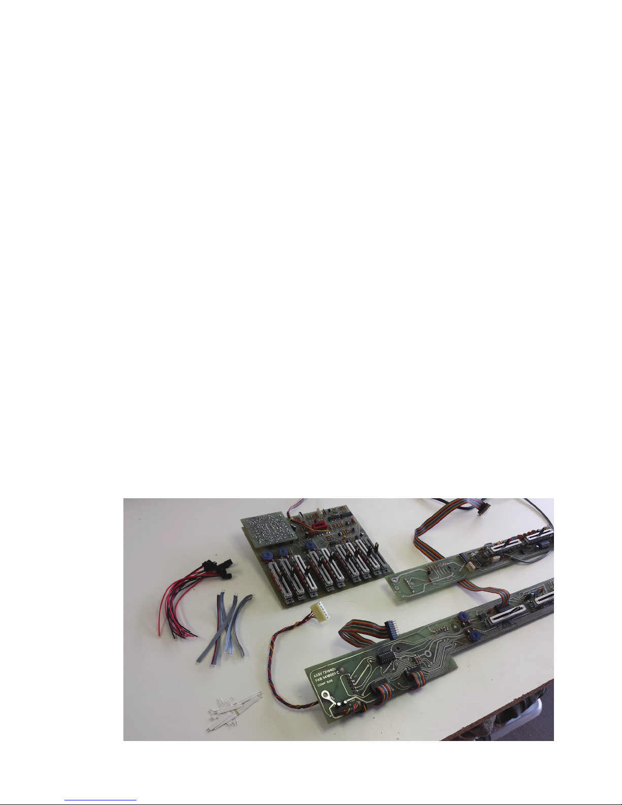
Figure 1 - Test Fiing all Sliders (ARP Omni 2 shown)
Page 4
2) Using the PCB pas diagrams in Drawing 1,2, and 3, place all of the slider assemblies into the PCB as shown in figure 1. DO NOT SOLDER YET. This
allows for the chance to test fit the assemblies, and also makes it easier to
wire the sliders together. Be sure to use the slider adapter with the transistor driver for the LFO RATE slider. This slider adapter allows the LFO to modulate the brightness of that slider’s LED.
3) Double check the slider values and tapers. Using the jumper cables included with the sliders, begin wiring the slider assemblies as shown in figures XX-XX. Be sure to wire all V+ pins together, and all GND pins together. It
is easy to make a mistake and reverse the polarities when using the longer
cables. Be sure to double check your work before you solder.
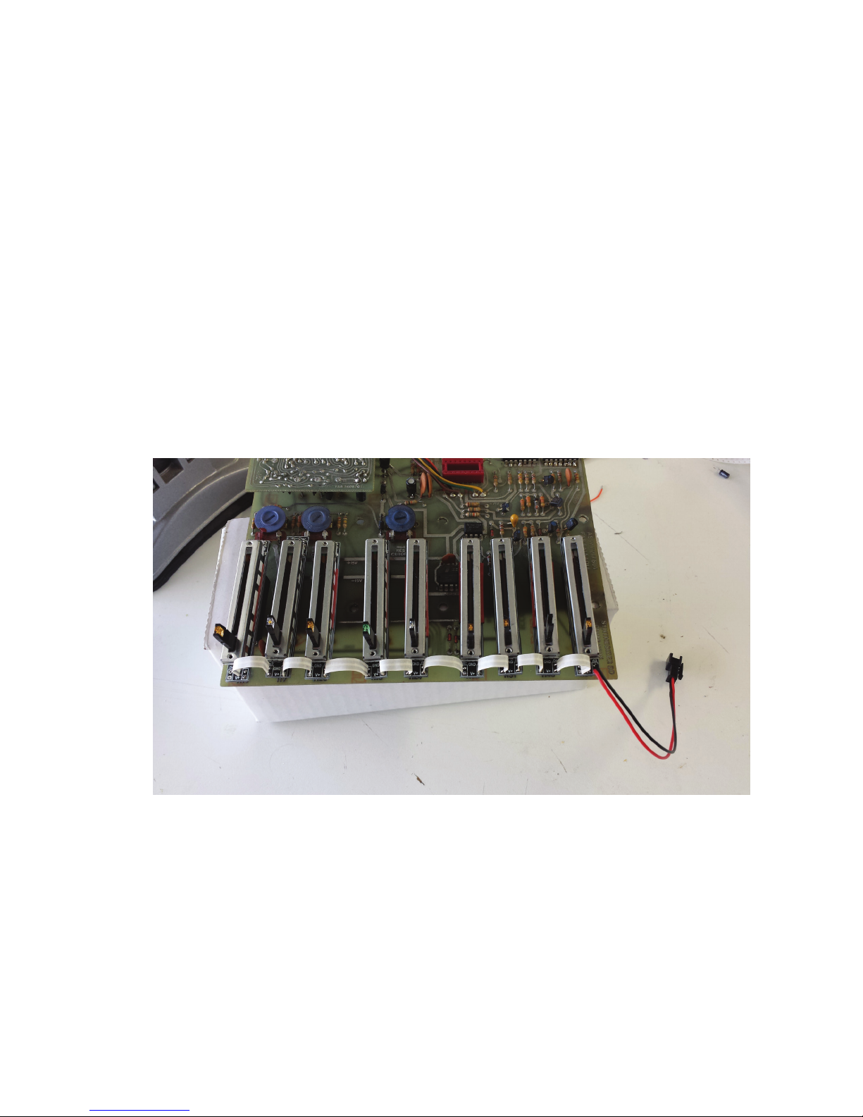
Figure 2 - Slider Wiring Assembly Completed. (Sliders still just loosely placed into PCB. ARP Omni 2 shown)
Build wire assemblies. When completed, the assemblies should still be
placed loosely into the PCB, as shown in Figure 2.
4) Using elastic bands, clips or other means, hold the sliders into place so
the PCB can be flipped over for soldering. Don’t worry if the sliders are
straight. They will all be aligned and straightened when the assembly is tack
soldered into place. THE SLIDERS MUST BE TACK SOLDERED INTO PLACE BY
ONLY ONE PIN. This will allow the slider assemblies to be held in place on
each PCB while each slider is leveled and aligned.
Page 5
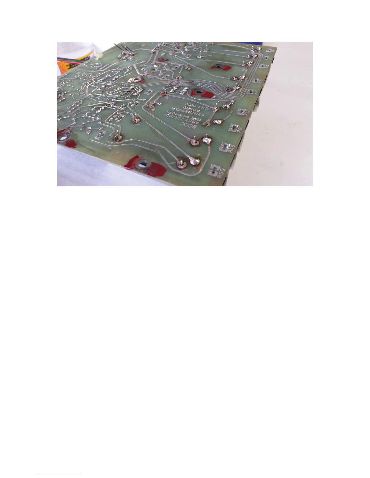
Figure 3 - Sliders Assembly Tack Soldered (Each slider soldered in place by only one pin)
Now that the slider asseblies are held in place, heat up the tack
solder joint holding each slider into place and adjust so that slider
shas are perpendicular to the pcb and the slider PCB is parallel with
the ARP PCB. Notice that the sliders can easily be moved into alignment by gently moiving them or heating up the tack solder joint.
Don’t hold the soldering iron tip to the tack solder joint for more than
2-4 seconds. Too much heat can cause the slider adapter PCB pins to
become unsoldered.
You can now test fit the PCB to the chassis. When you have fit the
PCB back into the chassis of the synth, screw the PCB into place. Adjust any sliders that arent straight, then solder each sliders remaining
pins int the PCB. When the PCBs are screwed into the chassis, you
can gently hold the slider into the desired position and solder the
remaining legs.
Page 6
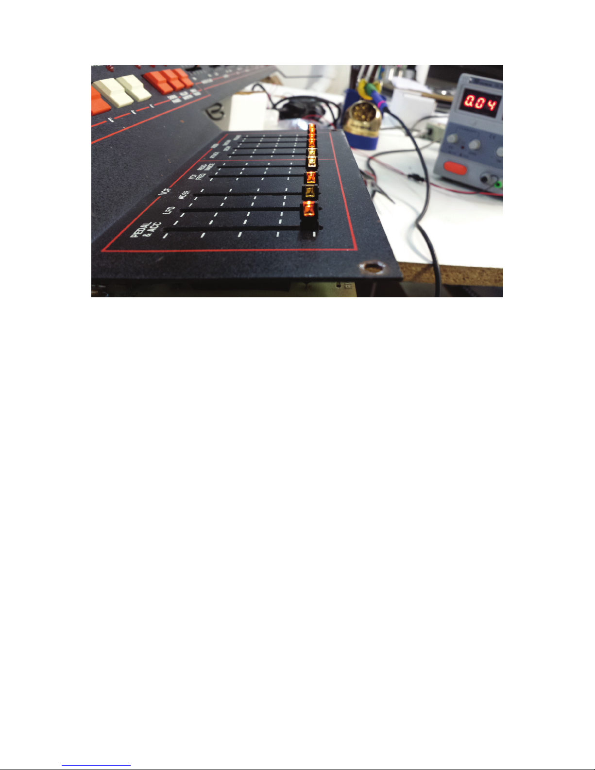
Figure 4 - Slider Assemblies Wired Into PCBs (All sliders aligned. ARP OMNI 2 shown)
5) When the assemblies have been wired to the PCBs, you can connect
each PCB to the LED power supply using the mating connectors. This
allows for brightness adjustment of each LED. Note that the LFO RATE
slider won’t be lit. This LED will only light if the LFO on the ARP is running.
In this case, we will only be running the LED circuit on the sliders. This
step can be done aer you have wired the 5V LED supply into place.
Using a preferably non conductive jewelers screw driver, adjust the LED
brightness for each slider. If using custom colors, be sure to cut the legs
of the enclosed LEDs to the same length as the legs of the LEDs that
came mounted in the sliders. If the LED is put into the slider backwards,
that LED will not light. Reverse LED polarity if this happens.
Page 7

Figure 5 - Slider Assembly Powered. (LED brightness being adjusted on each slider)
Page 8

Figure 6 - ARP Odyssey 2800 Board A Installed
Page 9

Figure 7 - ARP Odyssey 2800 Board B Installed (Note that this wiring is different from the suggested method as shown in PCB drawings below)
Page 10

Figure 8 - ARP Odyssey 2800 Board C Sliders Installed
Page 11

1MD
GND
V+
FEMALE CONNECTOR
Drawing 1 - ARP Odyssey 2800 Suggested Wiring Diagram (BOARD A)
Page 12

100KB 100KB 100KB
100KB 100KB 100KB 100KB
SRC
100KD
FEMALE CONNECTOR TO BD C
MALE CONNECTOR TO BD A
GND
GND
GND
V+
V+
100KD 100KD 100KD 100KD 100KD
GND
V+
100KB
GND
GND
V+
V+
GND
V+
GND
GND
V+
V+
V+
100KB 100KB 100KB
100KD
GND
GND
V+
GND
V+
V+
GND
V+
1MD
GND
GND
V+
V+
GND
V+
Drawing 2 - ARP Odyssey 2800 Suggested Wiring Diagram (BOARD B)
Page 13

100KB 100KB
100KB
V+
GND
100KB
1MD
1MD
FEMALE CONNECTOR TO 5V POWER SUPPLY
MALE CONNECTOR TO BD B
100KD
100KB
1MD
GND
V+
100KD
GND
GND
V+
1MD
GND
GND
V+
V+
GND
V+
V+
1MD
100KB
1MD
GND
GND
V+
GND
V+
V+
GND
GND
V+
V+
100KD
100KD
GND
GND
V+
V+
100KB
100KB
GND
GND
V+
GND
V+
V+
Drawing 3 - ARP Odyssey 2800 Suggested Wiring Diagram (BOARD C)
Page 14

INSTALLING LED POWER
1) The 5V LED ballast should be mounted close to the transformer in your
ARP’s power supply. The ballast is powered by the AC hot and neutral, the
same as the transformer on the ARP.
Find a location near the transformer where the ballast can be mounted.
Use the mounting template and make staer marks using a punch. Drill
the mounting holes for the ballast, then mount the ballast using the nuts
and bolts included in the kit. See figures 9, 10, and 11 for example using
ARP Omni 2.
Figure 10 - Test Fit Power Supply
Page 15

Figure 11 - Marking Mounting Holes for Drilling
Figure 12 - Power Supply Mounted In Case
Page 16

5) On the ARP, one side of the AC is switched on and off by the power switch.
This wire also runs through a 250V 500mA fuse. Aach the ballast AC inputs
at the same spot the primary winding of the transformer aach to the AC and
the fused AC. Doing this will allow for the ballast to be switched on and off
with the synth’s power switch.
Figure 13 - AC Mains Wiring for LED Ballast
6) The ground (black wire) of the 5V ballast must be connected to the
ground of your ARP’s power supply. This is done to provide a ground
reference to the blinking sliders so they can track the level of LFOs,
ADSRs, etc. Figure 14 shows the extra grounding wire. If you are not using any blinking sliders on your synth, you can omit this extra wire. Be
sure that the wire is long enough to reach the DC ground on your ARP
power supply. Now you can daisy chain LED sliders from this ballast.
Page 17

Figure 14 - Extra Grounding Wire & 5V Power Wiring
Figure 15 - Finished LED Ballast Wiring
 Loading...