

Page 1
OWNER’S MANUAL
Page 2

Precautions
Location
Using the unit in the following locations can result in a malfunction.
• In direct sunlight
• Locations of extreme temperature or humidity
• Excessively dusty or dirty locations
• Locations of excessive vibration
• Close to magnetic fields
Power supply
Please connect the designated AC adapter to an AC outlet of the correct voltage. Do not connect it
to an AC outlet of voltage other than that for which your unit is intended.
Interference with other electrical devices
Radios and televisions placed nearby may experience reception interference. Operate this unit at a
suitable distance from radios and televisions.
Handling
To avoid breakage, do not apply excessive force to the switches or controls.
Care
If the exterior becomes dirty, wipe it with a clean, dry cloth. Do not use liquid cleaners such as
benzene or thinner, or cleaning compounds or flammable polishes.
Keep this manual
After reading this manual, please keep it for later reference.
Keeping foreign matter out of your equipment
Never set any container with liquid in it near this equipment. If liquid gets into the equipment, it
could cause a breakdown, fire, or electrical shock.
Be careful not to let metal objects get into the equipment. If something does slip into the
equipment, unplug the AC adapter from the wall outlet. Then contact your nearest Korg dealer or
the store where the equipment was purchased.
THE FCC REGULATION WARNING (for U.S.A.)
This equipment has been tested and found to comply with the limits for a Class B digital device, pursuant to Part 15 of the FCC
Rules. These limits are designed to provide reasonable protection against harmful interference in a residential installation. This
equipment generates, uses, and can radiate radio frequency energy and, if not installed and used in accordance with the
instructions, may cause harmful interference to radio communications. However, there is no guarantee that interference will
not occur in a particular installation. If this equipment does cause harmful interference to radio or television reception, which
can be determined by turning the equipment off and on, the user is encouraged to try to correct the interference by one or more
of the following measures:
• Reorient or relocate the receiving antenna.
• Increase the separation between the equipment and receiver.
• Connect the equipment into an outlet on a circuit different from that to which the receiver is connected.
• Consult the dealer or an experienced radio/TV technician for help.
Unauthorized changes or modification to this system can void the user’s authority to operate this equipment.
CE mark for European Harmonized Standards
CE mark which is attached to our company’s products of AC mains operated apparatus until December 31, 1996 means it
conforms to EMC Directive (89/336/EEC) and CE mark Directive (93/68/EEC).
And, CE mark which is attached after January 1, 1997 means it conforms to EMC Directive (89/336/EEC), CE mark Directive
(93/68/EEC) and Low Voltage Directive (73/23/EEC).
Also, CE mark which is attached to our company’s products of Battery operated apparatus means it conforms to EMC Directive
(89/336/EEC) and CE mark Directive (93/68/EEC).
Page 3

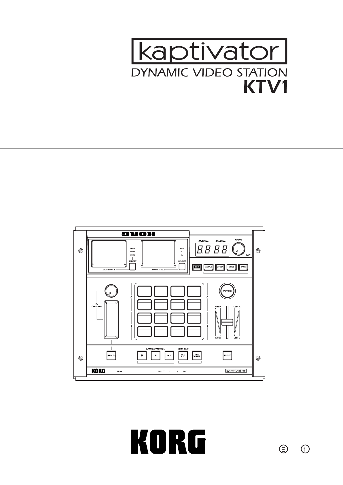
Thank you for your purchase of the KORG kaptivator Dynamic video station.
To enjoy long and trouble-free use of this device, please read this manual carefully and operate the unit
correctly.
A note about using this video device
Some people subjected to stimulation by intense light or rapidly flashing images may experience symptoms of
temporary muscle spasms or loss of consciousness. If you experience any such symptoms, stop using this device
immediately and seek medical attention.
In particular when using this device in a public place or other location where there are large numbers of people,
you must take into account people other than the operator, and avoid creating and displaying continuous successions of images that might produce this type of intense stimulation.
Korg Corporation accepts no responsibility for any health problem or personal or property damage that may occur
to the operator or observers from use of this device in violation of this warning.
About your data
The contents of memory may be lost if an unexpected malfunction occurs, so be sure to make a backup of any
important data. Korg Corporation can take no responsibility for any damages due to loss of data.
Handling of the internal hard disk
Do not apply physical shock to this device. In particular, you must never move this device or apply physical shock
while the power is turned on. This can cause part or all of the data on disk to be lost, or may damage the hard disk
or interior components.
When this device is moved to a location where the temperature is radically different, water droplets may condense
on the hard disk. If the device is used in this condition, it may malfunction, so please allow several hours to pass
before operating the device.
Do not repeatedly turn the power on/off. This may damage the kaptivator.
This device begins to access the hard disk immediately after the power is turned on.
Never turn off the power while the BUSY indicator is lit or blinking. Doing so can cause all or part of the data on
hard disk to be lost, or may cause malfunctions such as hard disk damage.
If the hard disk has been damaged due to incorrect operation, power failure, or accidental interruption of the
power supply, a fee may be charged for replacement even if this device is still within its warranty period.
Owner’s Manual
COPYRIGHT WARNING
This professional device is intended only for use with works for which you yourself own the copyright, for which
you have received permission from the copyright holder to publicly perform, record, broadcast, sell, and duplicate, or in connection with activities which constitute “fair use” under copyright law. If you are not the copyright
holder, have not received permission from the copyright holder, or have not engaged in fair use of the works, you
may be violating copyright law, and may be liable for damages and penalties. If you are unsure about your rights
to a work, please consult a copyright attorney.
KORG TAKES NO RESPONSIBILITY FOR ANY INFRINGEMENT COMMITTED THROUGH USE OF KORG
PRODUCTS.
About the video clip collection
Copyright to the “video clip collection” built into the kaptivator is the property of the respective copyright holders, and Korg Corporation has obtained permission to use this material.
You may use this “video clip collection” in public locations only if you are using the kaptivator.
Whether in part or in whole, duplicating, selling, lending, distributing, or making this material available on the
Internet etc., whether for profit or otherwise, will constitute a violation of copyright law.
* Appearance and specifications of this product are subject to change without notice.
Company names, product names, and names of f ormats etc. are the tr ademarks or registered
trademarks of their respective owners.
1
Page 4

Table of Contents
Introduction ....................................... 3
Basic operation — Playback ............. 12
Customizing a Style —Style Editing ... 19
Creating a clip —Sampling and Quick
1. Main features ........................................................ 3
2. Controls and connectors ......................................... 4
3. Connection diagram............................................... 9
4. Basic concepts and operation................................ 10
1. Turning the power on/off...................................... 12
2. Selecting and playing video .................................. 13
3. Working with external video sources ..................... 14
4. Synchronizing to music......................................... 15
5. Using Motion Sequences....................................... 17
1. Editing a style ...................................................... 19
Editing ......................................... 21
1. Sampling............................................................. 21
2. Clips ................................................................... 23
3. Banks .................................................................. 25
Utility mode ..................................... 26
1. Operations in Utility mode .................................... 26
2. Utility menu items and procedures ......................... 27
Parameter list................................... 31
Style Parameter List.................................................... 31
Routing list ................................................................ 34
Transition list ............................................................. 38
Effect list ................................................................... 39
Clip parameter list ..................................................... 40
Appendix ........................................ 44
Tips for working with the kaptivator ............................ 44
Trobleshooting........................................................... 47
Preset Style list........................................................... 48
Specifications............................................................ 48
Style Cheat ...................................... 93
Preset ....................................................................... 93
User ......................................................................... 96
2
Page 5

Introduction
Thank you for purchasing the kaptivator.
The kaptivator Dynamic Video Station is a video performance instrument that allows you to sample
video, store and playback video samples (“clips”), apply effect processing, and mix live and stored
video signals, all in realtime without having to use any additional equipment.
Its superb reliability and operational ease will allow you to create video performances as never before.
1. Main features
•Video performance and sampling instrument.
• Intuitive, easy-to-use design is based on familiar music sampler-style controls and interface.
• Quickly sample and playback video; mix video sources; add and manipulate video effects; - all
in real time.
• Sample and store up to 800 clips (approximately 106 minutes - maximum ten minutes per clip)
to the internal hard drive and play them from the sixteen clip pads.
• Pads are divided into two groups (Group A and Group B), allowing you to play and mix two
sources simultaneously. A third external video input source can also be added to the mix.
•Two color LCD monitors allow you to simultaneously monitor the external input, output and
internal video sources.
• Assigning an index image to each clip allows the video content of the sixteen pads to be seen
all at once.
• Exclusive storage format with minimal compression allows smooth video effects such as speed
change, reverse, random playback, or scratching during playback.
• The rotary knob, ribbon and slider provide performance control over mixing, effects, and playback speed.
• Any one of the fifteen video effects can be applied to any video source, clip or mix.
• One hundred programmable “styles” can be saved and quickly recalled; each one memorizes
specific video routing, effect and controller assignments.
• The Motion Sequence function lets you record all your front panel controller movements and
effect changes. One hundred Motion Sequences can be stored and played back with any style.
• Move to the music! The kaptivator can detect the tempo, level changes and audio triggers from
an external audio source and use them to control the effects, mix levels, etc.
• The BPM setting lets you match the video playback speed to the tempo of your music.
• The “Main Out Capture” function can grab up to eight seconds of video signal from the MAIN
OUT jack to be used as an additional source for mixing and effect processing, or to be resampled
and saved to a clip.
•A DV connector is provided, allowing you to input or output digital video format (DV) signals
to/from a DV camera or other device.
•PAL/NTSC video signal formats are supported.
•A simple PAL/NTSC conversion function allows you to play back video that was recorded in
either format.
•Contains dynamic and visually exciting video clips and images created by cutting-edge VJ and
video artists.
Owner’s Manual
3
Page 6
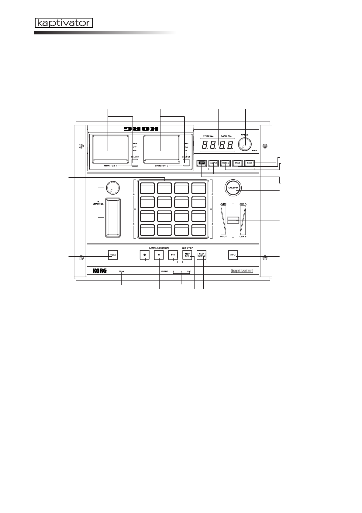
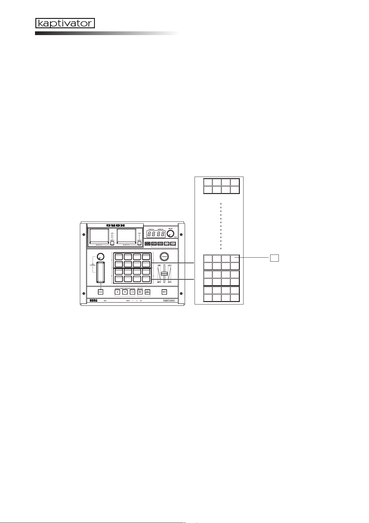
2. Controls and connectors
A. Top panel
12 345
6
7
10
11
12
13
14
15
8
9
16
17
22 21
20
1. MONITOR 1, SELECT key
MONITOR 1 generally displays the video signal that is being sent from the MAIN OUT jack
(MAIN). It can also display the video signals coming in through the VIDEO INPUT 1 (INPUT 1) or VIDEO INPUT 2 (INPUT 2) jacks.
Press the SELECT key to choose one of the three modes described above. (☞ p.12)
Holding down the EDIT key and pressing the SELECT key will allow you to adjust the
brightness, contrast, and color balance of MONITOR 1. (☞ p.12)
2. MONITOR 2, SELECT key
In MONITOR 2, you can choose to view all the clips currently assigned to the clip pads
(BANK), the playback status of each position of the current routing assignment (ALL), as
well as the digital video signal (DV) that is being received at the DV I/O connector.
Press the SELECT key to choose one of the three modes described above. (☞ p.12)
The DV input image cannot be selected if the DV I/O connector is set to OUT. (☞ p.9)
Holding down the EDIT key and pressing the SELECT key will allow you to adjust the
brightness, contrast, and color balance of MONITOR 2. (☞ p.12)
1918
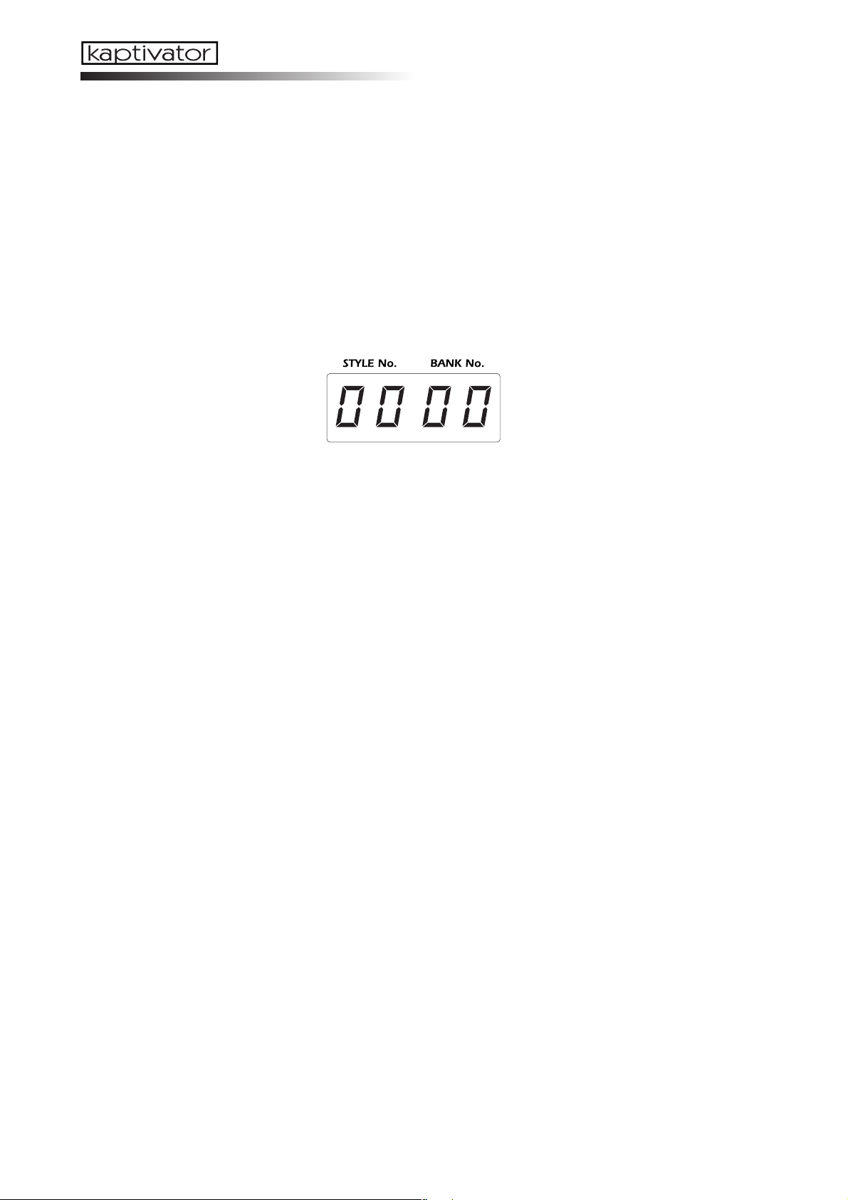
3. VALUE display
This shows the bank and style number, the name and value of the current parameter, and
other status information.
4
Page 7

4. VALUE knob
This knob is used to both select and change the value of various parameters.
This knob can also be used as an addition controller (Ext Value) by holding down the YES/
WRITE key and turning the VALUE knob. When using the factory settings, this function will
control the dissolve rate (the time for transitioning between clips). Style Edit parameters
allow you to assign various parameters to this function.(☞ p.19, 31)
5. BUSY indicator
When this indicator is lit, data is either being read from or written to the internal hard drive.
In normal operation, pressing the NO/ESC key will stop the currently-playing clip, and the
BUSY indicator will go dark.
NOTE Never turn off the power while the BUSY indicator is lit. Doing so ma y damage the hard disk.
6. CLIP pads
These pads are used to select and play sampled video clips. There are sixteen pads; the upper eight are Group A, and the lower eight are Group B. Group A is green, and Group B is
orange. The currently selected key will light red. Choose “BANK” for MONITOR 2 to see
the list of clips in the INDEX screen.
In Clip Edit, you can specify the playback points, the index frame, and a playback pattern
(such as one-shot, loop, or reverse) for each clip.
7. FX CONTROL knob controller
This knob is mainly used to provide realtime control of the effects. The parameter being adjusted by the knob will depend on the style or effect that is currently selected.
Style Edit parameters allow you to assign the knob to a variety of different functions.
Owner’s Manual
8. FX CONTROL ribbon controller
The ribbon controller is mainly used to provide realtime control of the effects. Two parameters can be assigned to the ribbon: touching the ribbon, regardless of position, can be assigned to one parameter; position on the ribbon to another. The parameters being adjusted
by the ribbon controller will depend on the style or effect that is currently selected.
Style Edit parameters allow you to assign the ribbon controller to various functions.
9. HOLD key
When the HOLD key is turned on (lit red), the last value detected by the ribbon controller
will be held, and will continue to apply the effect in its current state. .
Style Edit parameters allow you to assign this key to various functions.
10. BANK key
Each time you press the BANK key, it will toggle between Group A (green) and Group B
(orange). When the BANK key is blinking green, you can assign a bank of clips to the upper eight CLIP pads, or group A. When the BANK key is blinking orange, you can assign a
bank of clips to the lower eight CLIP pads, or Group B. If the BANK key is not blinking (i.e.
when the STYLE key is blinking), pressing it will also switch MONITOR 2 to the BANK
setting.
11. STYLE key
Each time you press the STYLE key, it will alternate between selecting styles (green) and
selecting effects (orange). When the STYLE key is blinking green, you can use the VALUE
knob to select a style . When the STYLE key is blinking orange, you can use the VALUE knob
to select an effect. If the STYLE key is not blinking (i.e. when the BANK key is blinking),
pressing it will also switch MONITOR 2 to the ALL setting.
5
Page 8

12. MOTION key
Press this key to enter Motion Sequence mode. When this key is blinking red, you are in the
Motion Sequence mode. Here you can select, record and playback the operation of the FX
CONTROL knob & ribbon, slider, CLIP pads, HOLD key, etc. Press this key again to exit
Motion Sequence mode. You cannot exit this mode while a Motion Sequence is playing.
13. SAMPLE key
Press this key to enter Sample mode. When this key is blinking red, you are in the Sample
mode. Here you can record (sample), edit and save video information, or “clips”. Press this
key again to exit Sample mode. You cannot exit this mode if an empty clip is selected.
14. EDIT key
The EDIT key is used in conjunction with other keys to access a variety of editable parameters and functions. When the SAMPLE, MOTION, STYLE or BANK keys are blinking,
holding down the EDIT key while you press one of these blinking keys will access the edit
functions for that mode. Hold down the EDIT key while you press the INPUT key to select
whether the DV jack is set to input or output. Hold down the EDIT key while you press the
YES/WRITE key to access the Utility mode. Hold down the EDIT KEY and press one of the
clip pads to edit the actual clip itself. This key will blink red while you’re editing. Press the
NO/ESC key twice to exit the current edit mode.
15. TAP/BPM key
The kaptivator can be set to start and play clips, as well as vary certain effect parameters in sync
with a BPM tempo source. This key is used when selecting the Manual mode, where the tempo
is set by the kaptivator’s internal clock; to tap in a tempo in the Tap Tempo mode; or to arm the
kaptivator to detect an external audio tempo source in the Auto BPM mode. This key will flash
red on each beat, and flash green on the first beat of the measure (every four beats). While the
tempo is being edited, this key will flash orange until the new tempo is entered.
16. Slider
Primarily, the Slider is used to crossfade between two video sources or images.
Style Edit parameters also allow you to assign the Slider to various functions.
17. INPUT key
Pressing this key will cycle through the various video sources that can be connected to the
kaptivator. The input source that is currently selected will be the one that is processed and
used by the kaptivator. Each time you press this key, the input signal will change from
INPUT 1 ➝ INPUT 2 ➝ DV-IN (only if selected) ➝ OFF (black screen) ➝ INPUT 1 ...
The VIDEO INPUT indicator (see 21.) shows which source is currently selected
The lit color of this key indicates the type of routing specified by the current style.
Red = single, Dark (unlit) = dual, Green = 3 layer, Orange = separate output (☞ p.14)
18. YES/WRITE key
Press this key to finalize a setting or execute an operation.
19. NO/ESC key
Use this key to cancel a setting or operation. In normal operation, pressing this key while
a clip is playing back will stop playback.
20. ● / ■ / (REC/STOP/START&PAUSE) key
These keys are used in Sampling mode and Motion Sequence mode.
When playing back a Motion Sequence, the
ture mode, the key will blink red if there is data in the Capture buffer, and will be lit red
as the Capture file plays.
key will be lit green. In the Main Out Cap-
6
Page 9
21. VIDEO INPUT indicator
This indicator shows which video input source has been selected by using the INPUT key
(see 17.). (☞ p.14)
22. AUDIO TRIG indicator
This indicator will light when the level of the external audio signal (connected to the AUDIO TRIG INPUT ) exceeds the current TRIG LEVEL setting. (☞ p.16)
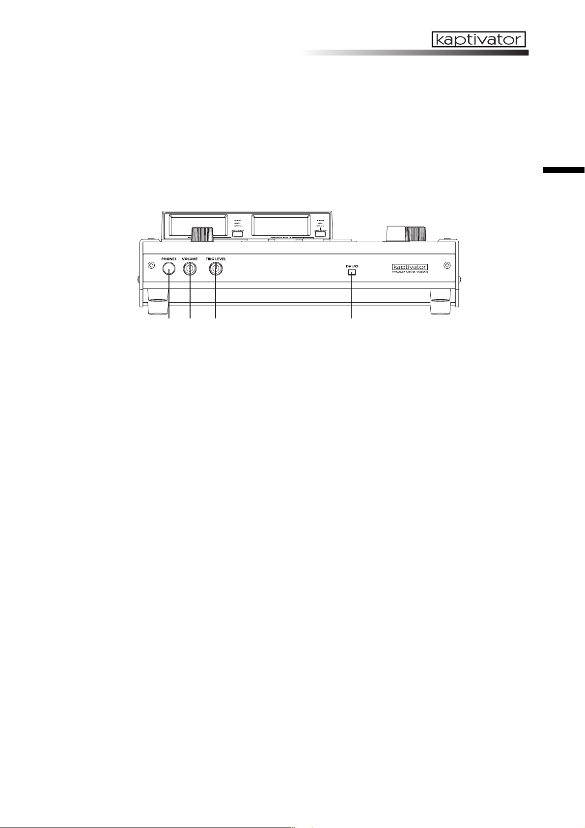
B.Front panel
12 3 4
1. PHONES jack
This stereo 1/4" headphone jack can be used to monitor the audio signal that is being received via the rear panel AUDIO TRIG INPUT jacks.
Owner’s Manual
2. PHONES volume knob
This adjusts the volume level of the headphone output.
3. TRIG LEVEL knob
This knob adjusts the audio trigger / effect control / auto BPM level. To set a reliable or
stable trigger level, you can adjust this knob while watching the AUDIO TRIG indicator.
4. DV I/O connector
The DV connector of your DV camera or the IEEE 1394 connector of your computer can be
connected to this jack. Only DV video signals can be received or sent from this connector.
This connector cannot transfer data such as files, or input/output audio signals.
7
Page 10

C.Rear panel
12345678
1. AUDIO TRIG INPUT L/R jacks
These RCA-style jacks can receive line-level audio signals. The incoming audio signal can
be used for BPM detection or to control effects.
2. VIDEO INPUT jacks
These jacks can receive video signals from a DVD player or other video devices.
VIDEO INPUT 1: Receives a composite video signal.
VIDEO INPUT 2: Receives an S-video signal.
3. MONITOR OUT jacks
These jacks transmit a video signal identical to what is currently displayed by the on-board
monitor screens.
MONITOR OUT 1: Transmits the image displayed by MONITOR 1.
MONITOR OUT 2: Transmits the image displayed by MONITOR 2.
4. MAIN OUT jacks
The MAIN OUT jacks send the final output of the kaptivator, after all the internal processing, mixing, etc. This is the same image that is displayed when you’ve set the MONITOR 1
SELECT setting to “MAIN”.
VIDEO: Transmits a composite video signal.
S-VIDEO: Transmits an S-video signal.
5. PAL/NTSC switch
This switches the video signal format (NTSC or PAL). You must turn off the power before
changing the setting of this switch.
6. MIDI IN / MIDI OUT connectors
You can use these jacks to connect the kaptivator to other MIDI devices - sequencers, music samplers (e.g., ESX-1), keyboards, etc..
7. Power supply jack
Here is where you plug in the power supply. Only use the dedicated AC adapter that was
included with the kaptivator.
8. Power switch
This switch turns the power on and off. And once again, never turn off the power while the
BUSY indicator is lit. Press the NO/ESC key until the BUSY indicator goes out; then you can
safely turn the power off.
8
Page 11
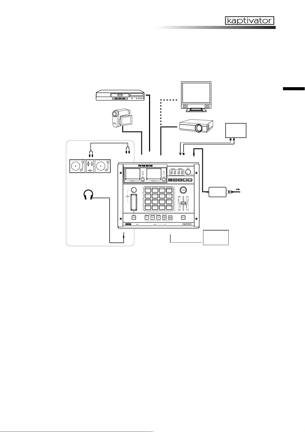
3. Connection diagram
Basic connections
DVD PLAYER
CAMCORDER
TV MONITOR
PROJECTOR
MIDI
sequencer
MIDI
OUT/IN
Owner’s Manual
AUDIO TRIG
INPUT
DJ Set
Headphones
PHONES
INPUT1
INPUT2
MAIN OUTPUT
DV I/O
MIDI
IN/OUT
DC12V
AC
AC ADAPTER
DVcamera,
DVrecorder etc.
IEEE1394
Selecting the DV connector input/output setting
1 Hold down the EDIT key and press the INPUT key.
2 Use the VALUE knob to select either “in” or “out” in the VALUE display.
3Press the YES/WRITE key twice. If you decide to cancel the setting, press the NO/ESC key
twice.
About video signal formats
The kaptivator supports both the NTSC and PAL video signal formats. NTSC is the format
used in the United States and Japan, while PAL is the format used in the United Kingdom
and Europe.
Set the NTSC/PAL switch according to the video signal format of the equipment you’re using. The kaptivator will not operate correctly if the video signal format is incorrect. Also, the
kaptivator will not operate correctly with non-interlaced video signals.
Playing copy-protected video from a commercial DVD
Copy-protected DVD video cannot be used as a video source. If you connect this type of
signal to the kaptivator’s INPUT jack, the image will not appear. In addition, a warning of
“PROTECTED” may appear in some cases, if you’ve selected ALL as the setting for MONITOR 2.
9
Page 12
4. Basic concepts and operation
Concepts
Sampling video
The kaptivator saves sampled video on its internal hard drive as “clips.”
These saved clips are managed as “banks”, each containing eight clips.
You can assign each of these banks to either of the two groups of clip pads (Group A contains the upper eight clip pads; Group B contains the lower eight) and play back these
sampled video clips. The same bank can be assigned to both groups simultaneously.
99
02
01
00
BANK
CLIP
Styles
The heart of the kaptivator’s ability to perform as a realtime video instrument is the Style.
Each individual style is really a complete processing scheme consisting of a specific routing
setting; a video effect; a transition setting; various controller assignments and more. You can
edit, create, modify and save 100 individual styles in the kaptivator. By simply switching to
a new style, you can instantly re-configure the kaptivator and all its settings.
10
Page 13

Terms
Style
Each “style” contains settings for routing, effects, playback synchronization, and controller
assignments. You can switch between styles during playback, or edit and store styles according to your needs. One hundred styles can be stored in the kaptivator.
Clip
A “clip” is an individual segment of sampled video material, together with its various settings, which can be saved, stored to a bank, and assigned to one of the sixteen clip pads. The
kaptivator can store up to 800 clips. You can specify the start point, stop point, loop point,
playback style and other settings for each clip.
Bank
A “bank” is a set of eight clips that can be assigned to the clip pads. You can create, save and
assign clips (“register”) up to one hundred banks.
Group
The sixteen clips pads are organized into two groups. Group A contains the upper eight clip
pads; and Group B, the lower eight. Each bank of clips can be assigned to either group - or
both. The settings saved in a style will apply to the entire group.
Routing
The kaptivator is extremely flexible, in that many of the elements of a style can be arranged
into different routing scenarios. For example, a routing setting can specify the number of
video sources (Group A, Group B, DV Camera in, etc.), which sources will be mixed by the
slider, where the effect processor is inserted (before the slider, after the slider, only to Group
A, etc.) along with what information is displayed in MONITOR 2 (with ALL selected).
Owner’s Manual
Motion Sequence
Your “live” movements - pressing clip pads, operating the slider and FX controllers, selecting banks, etc. - can be recorded as a Motion Sequence, and played back with any style. The
kaptivator will store up to 100 Motion Sequences.
BPM
BPM (Beats Per Minute) indicates the tempo of a song in terms of the number of quarter
notes per minute. Higher BPM settings indicate a faster tempo. The kaptivator can change
clips and vary effect parameters in sync with a BPM tempo source.
11
Page 14
Basic operation — Playback
1. Turning the power on/off
Power
To turn the power on
1 Connect the AC adapter, your input devices, and your output devices.
2Press the power switch to turn the power on.
After a few moments, the VALUE display will indicate the currently selected style and bank.
NOTE You can specify the bank and style number that will be selected when the power is turned on.
(☞ p.28)
To turn the power off
To turn the power off, press the NO/ESC key several times until the BUSY indicator goes
dark; then press the power switch to turn it off.
NOTE Never turn off the power while the BUSY indicator is lit. Doing so may damage the kaptivator’s
internal hard disk. So don’t do it.
Monitors
The two color LCD monitors display different content.
MONITOR 1 displays the MAIN OUT video signal, the video source connected to VIDEO
INPUT 1 or the video source connected VIDEO INPUT 2.
MONITOR 2 displays the bank list (a still image from each clip), all the video material associated with a style (inputs, output, transition, etc.) or the DV input.
Changing the content of the monitors
Pressing the MONITOR SELECT key will change the information being displayed in the
monitor associated with that key.
The content of the monitors can also be set to change automatically when you select a style.
(☞ p.30: Style Parameter List, Monitor select setting)
Adjusting the monitors
The monitors can be adjusted individually to provide easy visibility and to compensate for
factors such as viewing angle, location, surroundings, ambient lighting, etc.
1 Hold down the EDIT key and press the MONITOR 1 or 2 SELECT key.
2Pressing the EDIT key will cycle through the following parameters.
Brightness: “br” will blink in the VALUE display, followed by the current value (00–99)
Contrast: “cn” will blink in the VALUE display, followed by the current value (00–99)
Color Balance: “cL” will blink in the VALUE display, followed by the current value (00–99)
3 As you watch the monitor, turn the VALUE knob to set each parameter.
4Press the YES/WRITE key twice to save your settings.
If you decide not to save your settings, press the NO/ESC key twice.
12
Page 15

2. Selecting and playing video
Playing a clip
1Press one of the clip pad keys that are lit (green for Group A, orange for Group B).
The selected clip pad will light red, and the clip that is registered to that pad will play.
2 Use the ribbon controller or slider etc. to modify the video while it plays, or press another
clip pad to play a different clip.
NOTE Depending on the current style, you ma y not see anything in the MAIN output if the slider is set
to its minimum or maximum value . Set the slider to its middle or opposite position.
Changing the transition time between clips (Dissolve Rate)
To change the transition time between clips , hold down the YES/WRITE key. In the VALUE
display, “E - “ will start blinking. Continue to hold down the YES/WRITE key and turn the
VALUE knob to set the dissolve rate (00–99). When the value is 99, the transition time will
be approximately eight seconds.
Selecting a bank
1Press the BANK key. The currently selected bank number is indicated by the two right-hand
digits in the VALUE display.
2When the BANK key is blinking green, you can select a different bank for Group A. When
the BANK key is blinking orange, you can change the bank assigned to Group B.
3Press the MONITOR 2 SELECT key until the BANK indicator light is lit.
4 As you watch MONITOR 2, rotate the VALUE knob to select a different bank.
Owner’s Manual
Selecting a style
1 If you want to switch styles, press the STYLE key to enter Style mode. Each time you press
this key, you will alternate between selecting a style ( the STYLE key will blink green) and
changing the effect assigned to the current style (the STYLE key will blink orange).
2With the STYLE key blinking green, rotate the VALUE knob to change the style number,
indicated by the two left-hand digits in the VALUE display.
3Press the flashing YES/WRITE key to confirm your style selection.
If you decide not to change styles, press the flashing NO/ESC key, or use the VALUE knob
to return to the previous STYLE. The YES/WRITE and NO/ESC keys will stop flashing.
If you change styles while a clip is playing, the clip may stop. If you select a style that con-
tains a different routing, the clip will stop playing.
Changing the effect
1With the STYLE key blinking orange, rotate the VALUE knob to change the effect assigned
to the current style. The effect number is indicated by the two left-hand digits in the VALUE
display.
2Press the flashing YES/WRITE key to confirm the effect change.
If you decide not to change the effect, press the flashing NO/ESC key,
3 Operate the ribbon controller to see what the effect does.
NOTE If the current style is saved with “no effect” assigned, the V ALUE displa y will indicate “--” and y ou
won’t be able to change eff ects .
13
Page 16

3. Working with external video sources
Viewing an external video source
To view the video source connected to the VIDEO INPUT 1 jack, press the MONITOR 1 SELECT key to select INPUT 1. To view the video source being received by the INPUT 2 connector, select INPUT 2.
You can use MONITOR 2 to view the video source being received at the DV connector. Use
the MONITOR 2 SELECT key to choose DV.
NOTE Set the DV connector setting to “in.” (☞ p.9: DV connector in/out setting)
NOTE The image that is being input to the D V connector will be slightly delay ed. W e recommend that
you use the INPUT jack f or realtime use , such as for live video.
To select an external video source
Press the INPUT key to select one of the external video sources connected to the kaptivator.
The VIDEO INPUT indicator shows the status of the selected input.
Input 1 Lit: Currently selected
Blinking rapidly: No connection, or wrong signal format
Blinking slowly: Copy-protected signal was detected
Input 2 Lit: Currently selected
Blinking rapidly: No connection, or wrong signal format
Blinking slowly: Copy-protected signal was detected
DV Input Lit red: Currently selected (DV set to input)
Blinking rapidly: No connection
Blinking slowly: Copy-protected signal was detected
Green: Indicates that the DV connector is set to “Out”
dark (unlit) Input is off (black screen), or Main Out Capture is selected
Mixing an external video source with a clip
1Press the STYLE key until it blinks green.
2Turn the VALUE knob to select “31” (style number), and press the flashing YES/WRITE key.
For this example, we’ve chosen a style whose routing setting is “single.”
3Press the MONITOR 2 SELECT key to select ALL. This lets you monitor the video input, the
video selected by the clip pads, and the combination of these (the image that is sent from
MAIN OUT). Use the MONITOR 1 SELECT key to select MAIN. Now you can monitor the
mixed image (the image that is sent from MAIN OUT) in MONITOR 1.
4 Use the slider to mix between the external video source and the clip pad playback, and use
the ribbon controller to apply the effect assigned to this style. The effect will be assigned to
the clip pad playback, the external video source, or the mixed signal, depending on the
routing setting of the current style.
14
Page 17

4. Synchronizing to music
You can use the BPM setting or the playback from an external audio source to control the
playback speed or the start timing of a video clip, or to control the current effect.
NOTE If you synchronize the clip start timing to the BPM, it may be delayed by sever al fr ames.
Setting the BPM
Setting the BPM manually
1 Hold down the EDIT key and press the TAP/BPM key to select Manual mode.
2 Rotate the VALUE knob to change the BPM value shown in the VALUE display. The deci-
mal point in the display will blink.
3Press the YES/WRITE key or the TAP/TEMPO key to complete the setting. The decimal
point will stop blinking, indicating the new tempo is set. If you want to cancel the setting,
press the NO/ESC key.
NOTE You can't switch clips while setting the BPM.
The Tap Tempo function
If you don’t know the BPM value, press the TAP/BPM key three or more times in rhythm
with the song; the BPM of the song will be detected and shown in the display, and will be
assigned as the current BPM setting.
Owner’s Manual
Auto BPM setting
1 If you have a music source hooked up to the AUDIO TRIG INPUT jacks, hold down the
TAP/BPM key for three seconds or longer, and the kaptivator will automatically detect the
BPM of the song. You may have to adjust the TRIG LEVEL knob to get the best results. While
the BPM is being detected, the decimal point will blink and the TAP/BPM key will flash
orange.
NOTE The BPM cannot be detected if the music does not have a clear sense of beat.
2Press the YES/WRITE key to confirm the setting. The decimal point will stop blinking and
the TAP/TEMPO key will once again flash red on each beat, and green at the start of the
measure. If no tempo is detected, the kaptivator will continue to use the previous BPM
setting. If you decide to cancel, press the NO/ESC key.
NOTE You can’t switch clips while making the Auto BPM setting.
Synchronized playback using the BPM setting
Synchronizing the start of the clip to the BPM
1 Set the BPM using one of the methods described above.
2 Choose style number “88”.
This style sets the start mode to “T2” so that clips will start in sync with the BPM. (☞ p.31:
Style parameter list, p.19: Style edit)
3Press a clip pad. The clip will begin playing at the beginning of the measure (when the TAP/
TEMPO light flashes green).
Synchronizing the clip playback speed to the BPM
1 Set the BPM.
2 Choose style number “00”.
This style sets the clip “C3 (Playback reference speed setting)” to “r2” so that the clip play-
15
Page 18

back speed will change in sync with the BPM. (☞ p.31: Style parameter list, p.19: Style edit)
3 Select the clip that you want to play. Change the BPM. The clip playback speed will change
according to the BPM.
Synchronized playback using an audio trigger
Adjusting the audio trigger level
1 Connect the playback from as external audio device such as a CD player or a DJ mixer to the
AUDIO TRIG INPUT jacks.
2 As you watch the AUDIO TRIG indicator, adjust the trigger level using the TRIG LEVEL
knob. The AUDIO TRIG indicator shows the state of the audio signal trigger level.
Dark (unlit): No input detected, Green: Minimum level detected, Orange: Level detected,
Red: Maximum input
Synchronizing the start of the clip to the audio trigger
1 Adjust the trigger level to an appropriate level for the song, as described above.
2 Choose style number “87”.
This style sets the start variation to “T3” so that the clip will begin playing when the audio
input signal exceeds the trigger level. (☞ p.31: Style parameter list, p.19: Style edit)
3Press a clip pad. When the volume of the song exceeds the trigger level, the video clip will
begin playing.
Using an external audio signal to control an effect
1 In addition to using an audio trigger, variations in the input level of an external audio source
can also be used to control certain parameters.
Connect an external audio device and set the trigger level as described in the previous examples.
2 Choose style number “02”.
This style assigns the effect control setting to “A1,” and varies the parameter in synchronization with the trigger level. (☞ p.31: Style parameter list, p.19: Style edit)
3Touch the ribbon controller to operate it. The amount of blurring will change according to
the trigger level.
16
Page 19

5. Using Motion Sequences
You can record and save up to one hundred sets of controller movements as “motion se-
quences,” and then select a motion sequence and play it back when desired. In addition to
movements of the various controllers and operations on the clip pads, a motion sequence
can also include bank or style selections and changes.
Playing a motion sequence
1To enter Motion Sequence mode, press the MOTION key; the MOTION key will blink. Press
the blinking MOTION key to exit Motion Sequence mode.
2 Use the VALUE knob to change the motion sequence number “-**-” shown in the VALUE
display. If the “-” at both sides is blinking, this indicates an empty motion sequence that has
not yet been recorded.
3Press the YES/WRITE key to confirm your selection.
4Press the
5Press the STOP key to stop the motion sequence.
If you’ve assigned the motion to once, playback will end automatically.
6Press the blinking MOTION key to exit Motion Sequence mode. You can’t exit Motion Se-
quence mode unless the motion sequence is stopped.
Looping the playback of a motion sequence
1When the MOTION key is blinking, hold down the EDIT key and press the MOTION key;
the EDIT key and MOTION key will blink.
2 Use the VALUE knob to make the VALUE display read “LOOP.” Choose “ONCE” if you
don’t want the motion sequence to loop.
key to playback the motion sequence. Press the key once again to pause.
Owner’s Manual
Play repeatedly Play once
3Press the YES/WRITE key twice to confirm the setting.
Recording a motion sequence
1 If the MOTION key is blinking, you are already in Motion Sequence mode. To enter Motion
Sequence mode, press the MOTION key; the MOTION key will blink. Press the blinking
MOTION key to exit Motion Sequence mode.
2 Use the VALUE knob to change the motion sequence number “-**-” shown in the VALUE
display.
If the “-” at both sides is blinking, this indicates an empty motion sequence that has not yet
been recorded. Choose a motion sequence number that has not yet been recorded, and press
the YES/WRITE key.
NOTE If none of the motion sequences are empty, you’ll need to erase one. (☞ p.18: Erasing a mo-
tion sequence)
3Press the REC key to enter standby mode. (The REC key will blink.)
4 Recording will begin when you perform an operation that can be recorded as a motion se-
quence.
5Press the STOP key to stop recording the motion sequence.
17
Page 20

Erasing a motion sequence
1 If the MOTION key is blinking, you are already in Motion Sequence mode. To enter Motion
Sequence mode, press the MOTION key; the MOTION key will blink. Press the blinking
MOTION key to exit Motion Sequence mode.
2 Use the VALUE knob to select the motion sequence number “-**-” (shown in the VALUE dis-
play) that you want to erase, and then press the YES/WRITE key.
3 Hold down the EDIT key, the NO/ESC key, and the MOTION key (all simultaneously). Of
the motion sequence number (-**-), only the numerical portion will blink.
4Press the YES/WRITE key twice to erase the recorded motion sequence. If you decide not
to erase the motion sequence, press the NO/ESC key twice.
18
Page 21

Customizing a Style —Style Editing
The kaptivator lets you create and store one hundred “styles.” This section explains how you
can create styles that are appropriate for the video material you’re using and how you’re using it.
During performance, you can change effects, wipe types, and controller settings simply by
selecting a style.
NOTE The factory settings contain various styles programmed to demonstrate the kaptiv ator’ s capa-
bilities.
1. Editing a style
The effects of editing a style will depend on how the video sources are connected and on the
content of these sources.
Choosing a style
The most important element of a style is the “routing.” The routing determines the structure
of the video sources you can use. If you’re using only clips saved internally, choose the Dual
routing. If you’re using external video devices in your performance, choose the Single or
Three Layer routing. If you’re using the MONITOR 2 OUTPUT independently, choose the
Separate routing. See pages 33 through 37 for illustrations of the various routings available.
After you’ve selected the appropriate routing for your situation, you can assign the function
of each controller, and specify the effect and type variation.
Owner’s Manual
Style editing
1 Select the style that you want to edit.
2 Hold down the EDIT key and press the STYLE key. The display will indicate “A1.**” and the
EDIT key will blink.
3To edit the A1. parameter, use the VALUE knob to change the value shown in the VALUE
display.
NOTE The decimal point following the parameter v alue will light if the value is identical to the saved
value.
4To edit the next parameter, press the EDIT key. Each time you press the EDIT key you will
proceed to the next parameter. To return to the preceding parameter, hold down the EDIT
key and press the YES/WRITE key.
5To see the results of your editing, press the YES/WRITE key.
Now you can check the changes you made to the style.
At this point, you can use the VALUE knob to select the desired save-destination style and
press the YES/WRITE key to save the edited style and complete the procedure. If you want
to continue editing without saving your changes, press the NO/ESC key.
19
Page 22

Editing examples
Changing the operation of the ribbon controller
1 Select the style that you want to edit.
For this example, choose style number “04”.
2 Hold down the EDIT key and press the STYLE key. The display will indicate “A1.**” and the
EDIT key will blink.
3Press the EDIT key several times to choose parameter B5.
Here you can choose the controller that will modify the effect. To choose the ribbon controller, choose a setting in the range of “G1”–“G4.” With the “G1” setting, the effect will intensify as you move the controller from bottom to top. Conversely with the “G2” setting, the
effect will intensify as you move from top to bottom. With the “G3” setting, the effect is at
maximum at either end, and minimum in the center. The “G4” setting produces the opposite result, with the maximum effect in the center position.
4 When you’re finished editing, press the YES/WRITE key. Use the VALUE knob to select the
destination style location (style number) where you want to save the edited style. Then press
the YES/WRITE key to finish saving. If you decide not to save the changes you made, press
the NO/ESC key.
Changing the wipe type
1 Select the style that you want to edit.
For this example, choose style number “11”.
2 Hold down the EDIT key and press the STYLE key. The display will indicate “A1.**” and the
EDIT key will blink.
3Press the EDIT key several times to choose parameter A2.
This parameter specifies the type of transition. Choosing “00” will specify a fade. In this example, let’s select “03” to produce a wipe that changes the position of the images.
4Press the EDIT key to select parameter A3.
This selects the controller that will perform the wipe operation. Choose “F1” if you want to
specify the fader. Choose “F2” if you want to invert the direction of the fader operation.
5Press the EDIT key to select parameter A4.
This parameter specifies the type of wipe and the variable range of the controller. If you want
to create a wipe that pushes the image from left to right, specify a value in the range of “30”–
“39.” The second digit of the value specifies the range of fader movement. In this case, selecting “30” will produce a wipe using the entire range of the fader. Selecting “35” will wipe
using half the range of the fader. Selecting “39” will cause the image to switch at the midpoint of the fader.
6 When you’re finished editing, press the YES/WRITE key. Use the VALUE knob to select the
destination style location (style number) where you want to save the edited style. Then press
the YES/WRITE key to finish saving. If you decide not to save the changes you made, press
the NO/ESC key.
20
Page 23

Creating a clip —Sampling and Quick Editing
1. Sampling
Sampling video
Sampling a video input source
1Press the SAMPLE key; it will blink, and you will be in Sampling mode. You can press the
SAMPLE key once again to exit Sampling mode.
2 Use the VALUE knob to specify the sampling time. Samples are created and stored using
memory units that are 8 seconds long. You can specify a time length from eight seconds
through 600 seconds (ten minutes) in eight-second steps. The default is eight seconds.
NOTE The sampled video is managed in units of data that are each eight seconds long. F or e xample,
if the image you want to sample is fourteen seconds long, it will require two of these eight
second data units, and will actually occupy sixteen seconds of sampling time on the hard drive .
3 Selecting an empty clip.
If you press the YES/WRITE key at this time, a vacant clip pad in the lowest-numbered
available bank will be selected. You can also manually select any empty clip pad in any bank.
If you select a clip pad that already has a clip assigned to it, the display will indicate
“OCCP”. If there is not enough available storage space when you press the clip pad, the display will indicate “FULL”.
The kaptivator will be in sampling-ready mode. (The clip pad and the REC key will blink.)
4Press the INPUT key to select the external video input signal that you want to sample.
You can also apply an effect to the input video while sampling it. If you want to do this, press
the STYLE key at this point, turn the value knob to select an effect, and press the YES/
WRITE key.
NOTE The effect selected in this case is only applied to the image being sampled. This will not change
the effect setting of the style that was selected bef ore y ou entered SAMPLE mode .
Owner’s Manual
5Press the REC key to begin sampling. Press the STOP key to stop. Sampling will stop auto-
matically when the specified sampling time has elapsed.
6 If you want to continue sampling, press the YES/WRITE key to select the next empty clip,
rotate the VALUE dial to set the sampling time, and repeat steps 4 and 5.
7 If you are finished sampling press the SAMPLE key to exit Sampling mode. If the kaptivator
is in sampling-ready mode (The clip pad and the REC key are blinking), press the NO/ESC
key, and then press the blinking SAMPLE key to exit Sampling mode
NOTE The Clip Edit parameters allow to adjust the playbac k speed, start point, end point, playback
method, etc.
Time-lapse sampling
Extremely slow movements such as drifting clouds or opening flower blossoms can be captured using time-lapse video, and then played back to speed up the movement. Time-lapse
video can also be used to make common things like cars and people play back at an artificially fast speed.
1Press the SAMPLE key to enter Sampling mode.
2 Hold down the EDIT key and press the SAMPLE key; the EDIT key and SAMPLE key will
blink, and the display will indicate the time-lapse ratio.
NOTE You can turn the knob quickly to make larger changes in the numerical value.
21
Page 24

Turn the VALUE knob to specify the resulting playback speed.
You can specify a value between “1” and “5400” times normal.
For example if you’ve specified 8 seconds as the sampling time:
x “2” will record for 16 seconds, and the playback will be double-speed.
x “10” will record for approximately 1 minute 20 seconds, and the playback will be ten
times normal speed.
x “100” will record for approximately 13 minutes 20 seconds, and the playback will be
one hundred times normal speed.
x “1000” will record for approximately 2 hours 13 minutes 20 seconds, and the playback
will be one thousand times normal speed.
x “5400” (the maximum setting) will record for approximately 12 hours.
Press the YES/WRITE key twice to complete the Slow Sampling settings.
3 Begin recording the video as for conventional sampling.
NOTE If you’ re sampling from a camera, we recommend that y ou use a stable tripod. In addition, be
aware that since the lighting may change if you’re recording for an extended time, it’s a good
idea to use appropriate illumination.
Main Out Capture
Using this function, the processed and mixed video that is being sent from the MAIN OUT
jack can be temporarily captured into memory. This captured video can then be used as an
input source for further processing and mixing, used as an input source in Sample mode and
then “resampled” and saved to a clip. The Main Out Capture function can accommodate a
maximum of approximately eight seconds.
Capturing video and using it as an input source
1 Hold down the EDIT key and press the YES/WRITE key to enter Utility mode. In Utility
mode, enable the Main Out Capture function. (☞ p.27)
NOTE Any existing Main Out Capture data will be erased when y ou enter Utility mode.
NOTE The bank display response will be slower if y ou enab le Main Out Capture. (☞ p.27)
2 Exit Utility mode and return to Play mode.
3Press the REC key (you will be in Pause mode), and then press the REC key once again to
begin capturing.
4 Use the clip pads, sliders, and effects to control your video performance.
NOTE By pressing the key while capturing, you can continue capturing without stopping after
eight seconds. The eight seconds of video preceding the point at which you pressed the ST OP
key will be captured.
5 Capture will end when you press the STOP key or when approximately eight seconds have
elapsed. At this time, the key will blink red, indicating that capture has finished.
6 Using a style whose routing is other than “Dual,” press the INPUT key and select “CAP-
TURE” as the input source.
7Press the
clips etc.
8To delete the captured video, hold down the EDIT key, the NO/ESC key, and the PLAY key
(all three simultaneously).
key to play back the captured video, and perform as desired by mixing video
22
Resampling to a clip
If you want to resample the video as a clip, return to Sample mode and select “CAPTURE”
as the input signal.
Page 25

2. Clips
For each piece of video material that you sample, you can specify the playback start point,
end point, loop point and looping method; these settings can then be saved along with the
video material as a “clip.” Even when using the same piece of video material, you can
change the start point etc. and save it as a different clip.
Copying a clip
Here’s how you can copy an existing clip, edit it, and save the edited result in a different
bank.
Copying a single clip
1 Hold down the EDIT key and press the BANK key; the EDIT key and BANK key will blink,
and the Clip Copy operation will be selected. The clip pad that you want to copy is called
the copy-source, and the clip pad where the copy will be saved is the copy-destination.
2 Select the copy-source clip pad. In MONITOR 2, a red frame will appear around the copy-
source clip pad.
3 Select the copy-destination clip pad. A blue frame will appear around the copy-destination
clip pad.
NOTE You can’t copy to a location in which a clip has already been sav ed. If there is no av ailable cop y-
destination, you’ll need to erase a clip to make space.
4Press the YES/WRITE button twice to copy the clip.
Press the NO/ESC key once to un-select the copy destination (blue frame).
Press the No/ESC key a second time to un-select the copy-source (red frame).
To cancel the entire Clip Copy operation, be sure the copy destination and copy-source have
been un-selected, then press the NO/ESC key twice.
Owner’s Manual
Erasing a clip
Erasing the contents of a clip to create a blank clip
1 Hold down the EDIT key, the NO/ESC key, and the clip pad that you want to erase (all three
together).
The clip pad and the EDIT key will blink, and the VALUE display LED will blink “ErAS”.
2Press the YES/WRITE key twice to erase the selected clip. If you decide not to erase, press
the NO/ESC key twice.
NOTE You can’t erase a clip whose Protect setting was turned “on” in Clip Edit mode . You must first
turn Protect off before erasing the clip.
NOTE You can’t recover an erased clip. If the sampled video material used by the erased clip is not
used by any other clip , the sampled video material itself will also be erased.
Editing a clip
You can specify the way in which a clip will play, and the BPM value that determines its
playback speed. You can also protect a clip to prevent it from getting erased or modified.
Clip editing
1 Hold down the EDIT key and press the clip pad of the clip you want to edit. The selected
clip pad will blink orange during editing.
2Turn the VALUE knob to choose the clip Playback Type - T1. T2. T3 or T4 from pages 40
through 43. This is the first digit (after the “T”) in the VALUE display. (☞p.40, Playback Type
and Playback Pattern selection)
23
Page 26

3Press the EDIT key, and turn the VALUE knob to select the Playback Pattern. This is the
second digit in the VALUE display. (☞p.40, Playback Type and Playback Pattern selection)
If playback type 1 or type 3 was selected in step 2, use the following procedure to edit the clip
4a.) Press the EDIT key, and specify the start point using seconds (S.000) and frames (S.F.00).
NOTE Use the slider to adjust the seconds value, and use the V ALUE knob to adjust the fr ames .
b.) Press the EDIT key, and specify the end point using seconds (E.000) and frames (E.F.00).
c.) Press the EDIT key, and specify the loop point using seconds (L.000) and frames (L.F.00).
NOTE The loop point is only available if you selected playback type 3 in step 2
d.) Press the EDIT key, and specify the INDEX point using seconds (I.000) and frames
(I.F.00).the INDEX point will specify the point that you want to use as the still image in the
bank display.
e.) Press the EDIT key and rotate the VALUE knob to specify the BPM (b.000) value.
The BPM you specify here is used only if you select a style that includes a BPM synchronization function. You can also use the TAP/BPM key to enter the BPM value (☞ p.14).
Set the BPM value to match the sense of beat of the clip’s video material.
If playback type 2 or type 4 was selected in step 2, use the following procedure to edit the clip
4 a.) Press the EDIT key and rotate the VALUE knob to specify the BPM (b.000) value.
The BPM you specify here is used only if you select a style that includes a BPM synchronization function. You can also use the TAP/BPM key to enter the BPM value (☞ p.14).
Set the BPM value to match the sense of beat of the clip’s video material.
b.) Press the EDIT key, and specify the start point using seconds (S.000) and frames (S.F.00).
NOTE Use the slider to adjust the seconds value, and use the V ALUE knob to adjust the fr ames .
c.) Press the EDIT key, and set the end point by specifying the number of beats from the start
point (E.b.00)
d.) Press the EDIT key, and set the loop point by specifying the number of beats from the start
point (L.b.00)
NOTE The loop point is only available if you selected playback type 4 in step 2
e.) Press the EDIT key, and specify the INDEX point using seconds (I.000) and frames
(I.F.00).the INDEX point will specify the point that you want to use as the still image in the
bank display.
5 If you do not want to save your clip edits, press the NO/ESC key twice. To save your clip
edits, press the YES/WRITE key once. Now you can choose to Protect the clip, to prevent
further editing or accidental erasure. Use the VALUE knob to select Protect On (P. on) or Protect Off (P. oFF) and press the YES/WRITE key again to save your edits and Protect setting.
Turning Protect On or Off
1 Hold down the EDIT key and press the clip pad of the clip you want to edit.
2Press the YES/WRITE key.
3 Use the VALUE knob to turn the Protect setting on or off.
4Press the YES/WRITE key to save the setting.
24
Page 27

3. Banks
Eight clips are saved together as a “bank.” You can save one hundred banks of clips.
(Maximum 800 clips of 8 seconds; Maximum total video recording time is approximately 1
hour 46 minutes)
Selecting a bank
You can select a bank and assign it to either group of clip pads, Group A (the upper eight clip
pads) or Group B (the lower eight clip pads). You can select a new bank while a clip is playing and you can select the same bank for both groups.
Assigning a bank to a clip pad group
1Press the BANK key. When the BANK key is blinking green, you can assign a new bank to
Group A. When the BANK key is flashing orange, you can assign a new bank to Group B.
2 Use the VALUE knob to change the “BANK No.” indication shown in the VALUE display
and assign that bank to the selected group
Copying a bank
You can copy the currently selected bank by setting one group as the copy-source, and the
other as the copy-destination
Copying an entire bank of clips
1 Hold down the EDIT key and press the BANK key; the EDIT key and BANK key will blink,
and you’ll be ready to copy clips.
2 Use the VALUE knob to select the copy-source bank, and press any clip pad twice in the
copy-source bank. The eight copy-source clips shown in MONITOR 2 will be indicated by
a red frame. The BANK key will now indicate the other group
NOTE You can’t copy if you’ re unable to select a v acant bank. If there is no a vailab le copy-destination,
you’ll need to erase clips (☞p.23) to create a vacant bank.
Owner’s Manual
3 Use the VALUE knob to select the group for the copy-destination bank. If the copy-destina-
tion bank is empty, the eight clips will be indicated by a blue frame.
4Press the YES/WRITE button twice to copy the bank.
Press the NO/ESC key once to un-select the copy destination (blue frame).
Press the No/ESC key a second time to un-select the copy-source (red frame).
To cancel the entire Bank Copy operation, be sure the copy destination and copy-source have
been un-selected, then press the NO/ESC key twice.
25
Page 28

Utility mode
In this mode you can make basic settings and perform maintenance operations.
1. Operations in Utility mode
Entering Utility mode
Hold down the EDIT key and press the YES/WRITE key to enter Utility mode. The MONITOR 2 screen will show the Utility select screen.
NOTE You can’t play back clips in Utility mode.
Navigating the Utility mode
Press the EDIT key to choose a utility function. Each time you press the EDIT key the next
lower item will be selected. After you’ve selected the item you want to execute, press the
YES/WRITE key to display the options for the selected function. Many utility functions have
sub-menus that operate the same way. Once you have selected an individual feature, use the
VALUE knob to adjust the parameter. Press the YES/WRITE key twice to confirm your edit
and return to the previous menu. If you decide not to keep your edit, press the NO/ESC key
twice to return to the previous menu.
26
Page 29

2. Utility menu items and procedures
This section explains the content of each utility menu item, and how to use it.
HDD free:
This shows the remaining space on the hard disk.
Main out capture:
This enables/disables the Main Out Capture function. We recommend that you leave this
set to “Disable” unless you are currently using the Main Out Capture function. Leaving it
set to “Enable” while this function is not being used will slow down the bank list display.
Owner’s Manual
MIDI setting:
Here you can adjust the kaptivator’s MIDI settings, such as transmitting or receiving MIDI
clock, MIDI channel, and control change settings. The kaptivator cannot send and receive
MIDI clock information at the same time.
Setting the control change number
The kaptivator can receive or send MIDI clock for synchronizing with other devices, and can
be set to any MIDI channel. Additionally, each of the kaptivator’s controllers can be assigned
27
Page 30

a MIDI control change number from CC#1 through CC#31, CC#64 through CC#95, or Pitch
Bend. Each controller can also be individually set to enable (“CC”) or disable (“cc”). You cannot adjust the value of a disabled parameter.
Power on setup:
You can specify the style and the banks that will be selected when the power is turned on.
Backup:
Sampled video data and edited clip settings can be backed up to a DV camera or other external DV storage device. Global settings, style data and motion sequences (individually or
in blocks of ten) can be backed up to a MIDI filer, sequencer or other MIDI storage device.
The MIDI device must be able to initiate and send a dump request message.
Backing up video data to an external device
Sampled video together with its management data and clip data can be backed up to a DV
device in a single operation.
1 Enter Utility mode.
2Press the EDIT key to select “Backup,” and press the YES/WRITE key.
3 Select “Video data,” and press the YES/WRITE key.
28
Page 31

4 Select “Dump,” and press the YES/WRITE key.
5 Select “Dump start number.” Normally you will specify “000."
At this point, the MAIN out will display the following data screen:
Owner’s Manual
When this cut & clip data screen appears in MAIN out, put your external device in record
mode, and begin video recording.
6Press the YES/WRITE key twice to begin the backup.
The MAIN output will alternate between the cut & clip data screen and the cut image (maximum of approximately two hours). When the backup is completed, stop recording. NOTE
The resolution will be converted if you backup between different data formats (NTSC/PAL)
or operation modes (NTSC/PAL).
NOTE If you repeatedly backup and restore the same clip , the image quality will decline.
NOTE If you save NTSC data as a PAL signal, it will take approximately 1.2 times longer to save the
data. (If y ou save PAL data as an NTSC signal, it will take approximately 5/6 the time.)
Restoring video data
Sampled video and clip data can be restored in a single operation.
1 Enter Utility mode.
2Press the EDIT key to select “Backup,” and press the YES/WRITE key.
3 Select “Video data,” and press the YES/WRITE key.
4 Select “Restore,” and press the YES/WRITE key.
From your external device, play back the backup video into the kaptivator.
5 When the first clip data screen begins to play, immediately press the YES/WRITE key twice
to begin the restore operation.
When the restore operation is finished, stop playback. (When the operation is completed,
there will be an indication of whether errors occurred, and how many occurred.)
NOTE If you decide to cancel during the restore operation, the data will be in an incomplete state, and
will not be restored correctly. Also, if an error occurs during the operation, the video and data
lost at that point will affect any clip that ref erences that cut, so that it will not operate correctly.
NOTE If you performed a divided backup , the system will not operate correctly unless y ou restore the
complete set of backup data.
29
Page 32

Backing up style and motion sequence data
You can backup global data, style data, a single motion sequence, or a block of ten motion
sequences to a MIDI filer, sequencer or other MIDI storage device.
1 Enter Utility mode.
2Press the EDIT key to select “Backup,” and press the YES/WRITE key.
3Press the EDIT key to select “MIDI exclusive,” and press the YES/WRITE key.
Transmit a dump request message from your external device.
If you’re backing up motion sequence data, you’ll also need to specify the number or block.
When the kaptivator receives the dump request, it will transmit the backup data.
Restoring style or motion sequence data
You can restore the global data, style data, a single motion sequence, or block of ten motion
sequences that you saved as a backup file.
1 Enter Utility mode.
2Press the EDIT key to select “Backup,” and press the YES/WRITE key.
3Press the EDIT key to select “MIDI exclusive,” and press the YES/WRITE key.
Transmit the backup data from your external device.
NOTE Since the restore operation will sequentially overwrite the data within the kaptivator , halting the
restore operation before it has completed will mean that the motion sequence number that was
being written at that moment will contain no data (i.e., erased).
Preset Initialize:
At any time, you can always restore the kaptivator to its original factory settings - including style, clip, and global settings.
NOTE Never turn off the power while initializing.
30
Page 33

Parameter list
Routing settings Video Effect settings Group A
Operation settings
Group A
Time Effect setting
A1 Routing selection Single Dual 3Layer
Separate Output
11,12,13 21,22,23 31,32,33,34,35 41,42,43,44
A2 Tr ansition selection Fade Wipe1 Wipe2 Wipe3
00 01 02 03
A3 Controller selection Audio Beat Ribbon touch HOLD Ext value Slider Ribbon value Knob Fixed value
A1,A2,A3,A4 B1,B2,B3,B4 C1,C2,C3,C4 D1,D2,D3,D4 E1,E2,E3,E4 F1,F2,F3,F4 G1,G2,G3,G4 H1,H2,H3,H4 00–99
A4 Tr ansition Type selection Type 0 Type 1 Type 2 Type 3 Type 4 Type 5 Type 6 Type 7 Type 8 Type 9
/ Controller operating range 00–09 10–19 20–29 30–39 40–49 50–59 60–69 70–79 80–89 90–99
Audio Beat Ribbon touch HOLD Ext value Slider Ribbon value Knob Controller operating range
A1,A2,A3,A4 B1,B2,B3,B4 C1,C2,C3,C4 D1,D2,D3,D4 E1,E2,E3,E4 F1,F2,F3,F4 G1,G2,G3,G4 H1,H2,H3,H4 00–99 (A2=00 “Fade” only)
A5 (Transition 2 selection) Fade Wipe 1 Wipe 2 Wipe 3
00 01 02 03
A6 (Controller selection) Audio Beat Ribbon touch HOLD Ext value Slider Ribbon value Knob Fixed value
A1,A2,A3,A4 B1,B2,B3,B4 C1,C2,C3,C4 D1,D2,D3,D4 E1,E2,E3,E4 F1,F2,F3,F4 G1,G2,G3,G4 H1,H2,H3,H4 00–99
A7 (Transition Type selection Type 0 Type 1 Type 2 Type 3 Type 4 Type 5 Type 6 Type 7 Type 8 Type 9
/ Controller operating range) 00–09 10–19 20–29 30–39 40–49 50–59 60–69 70–79 80–89 90–99
Audio Beat Ribbon touch HOLD Ext value Slider Ribbon value Knob Controller operating range
A1,A2,A3,A4 B1,B2,B3,B4 C1,C2,C3,C4 D1,D2,D3,D4 E1,E2,E3,E4 F1,F2,F3,F4 G1,G2,G3,G4 H1,H2,H3,H4 00–99 (A2=00 “Fade” only)
A8 (Source exchange) Disabled Enabled
00 01
B1 Video Effect selection Off
Invert T op/Bottom Invert Left/Right
Rotate 180 Exciter Negative Color Change RGB
Separation
Emboss Brightness Contrast
-- 00 01 02 03 04 05 06 07 08 09
Feedback Blur Monotone Line drawing Binarize Through
10 11 12 13 14 15
B2 On/Off 1 controller selection Audio Beat Ribbon touch HOLD Ext value Slider Ribbon value Knob Always Off Always On
A1,A2,A3,A4 B1,B2,B3,B4 C1,C2,C3,C4 D1,D2,D3,D4 E1,E2,E3,E4 F1,F2,F3,F4 G1,G2,G3,G4 H1,H2,H3,H4 00 99
B3 On/Off 2 controller selection Audio Beat Ribbon touch HOLD Ext value Slider Ribbon value Knob Always Off Always On
A1,A2,A3,A4 B1,B2,B3,B4 C1,C2,C3,C4 D1,D2,D3,D4 E1,E2,E3,E4 F1,F2,F3,F4 G1,G2,G3,G4 H1,H2,H3,H4 00 99
B4 On/Off 1, 2 conditions Either Both
00 99
B5 VFX parameter 1 Audio Beat Ribbon touch HOLD Ext value Slider Ribbon value Knob Fixed value
A1,A2,A3,A4 B1,B2,B3,B4 C1,C2,C3,C4 D1,D2,D3,D4 E1,E2,E3,E4 F1,F2,F3,F4 G1,G2,G3,G4 H1,H2,H3,H4 00–99
B6 VFX parameter 2 Audio Beat Ribbon touch HOLD Ext value Slider Ribbon value Knob Fixed value
A1,A2,A3,A4 B1,B2,B3,B4 C1,C2,C3,C4 D1,D2,D3,D4 E1,E2,E3,E4 F1,F2,F3,F4 G1,G2,G3,G4 H1,H2,H3,H4 00–99
B7 VFX parameter 3 Audio Beat Ribbon touch HOLD Ext value Slider Ribbon value Knob Fixed value
A1,A2,A3,A4 B1,B2,B3,B4 C1,C2,C3,C4 D1,D2,D3,D4 E1,E2,E3,E4 F1,F2,F3,F4 G1,G2,G3,G4 H1,H2,H3,H4 00–99
C1 Start variation
Start when pressed Beat synchronized Audio level
Pause when released
Pause when pressed again
T1 T2 T3 T4 T5
C2 Dissolve (screen Audio Beat Ribbon touch HOLD Ext value Slider Ribbon value Knob Fixed value
switching speed) setting A1,A2,A3,A4 B1,B2,B3,B4 C1,C2,C3,C4 D1,D2,D3,D4 E1,E2,E3,E4 F1,F2,F3,F4 G1,G2,G3,G4 H1,H2,H3,H4 00–99
C3
Playback reference speed setting
Audio Beat Ribbon touch HOLD Ext value Slider Ribbon value Knob x1 BPM Freeze – x2
A1,A2,A3,A4 B1,B2,B3,B4 C1,C2,C3,C4 D1,D2,D3,D4 E1,E2,E3,E4 F1,F2,F3,F4 G1,G2,G3,G4 H1,H2,H3,H4 r1 r2 00–99
C4 Smoothing setting Enabled Disabled
00 99
D1 Time Effect selection Off Scratch
Reverse:Still:Forward
Still:Forward Reverse:Still x1:Forward Reverse:x1
-- 00 01 02 03 04 05
D2 On/Off 1 controller selection Audio Beat Ribbon touch HOLD Ext value Slider Ribbon value Knob Always Off Always On
A1,A2,A3,A4 B1,B2,B3,B4 C1,C2,C3,C4 D1,D2,D3,D4 E1,E2,E3,E4 F1,F2,F3,F4 G1,G2,G3,G4 H1,H2,H3,H4 00 99
D3 On/Off 2 controller selection Audio Beat Ribbon touch HOLD Ext value Slider Ribbon value Knob Always Off* Always On*
A1,A2,A3,A4 B1,B2,B3,B4 C1,C2,C3,C4 D1,D2,D3,D4 E1,E2,E3,E4 F1,F2,F3,F4 G1,G2,G3,G4 H1,H2,H3,H4 00 99
D4 On/Off 1, 2, conditions Either Both
00 99
D5
Parameter 1 controller selection
Audio Beat Ribbon touch HOLD Ext value Slider Ribbon value Knob Fixed value*
A1,A2,A3,A4 B1,B2,B3,B4 C1,C2,C3,C4 D1,D2,D3,D4 E1,E2,E3,E4 F1,F2,F3,F4 G1,G2,G3,G4 H1,H2,H3,H4 00–99
D6
Parameter 2 Controller selection
Audio Beat Ribbon touch HOLD Ext value Slider Ribbon value Knob Fixed value*
A1,A2,A3,A4 B1,B2,B3,B4 C1,C2,C3,C4 D1,D2,D3,D4 E1,E2,E3,E4 F1,F2,F3,F4 G1,G2,G3,G4 H1,H2,H3,H4 00–99
*Valid when D1 (Time Effect selection) is 00.
Style Parameter List
Owner’s Manual
31
Page 34

E1 Start variation
Same as Group A
Start when pressed Beat synchronized Audio level Pause when released Pause when pressed again
--
T1 T2 T3 T4 T5
E2 Dissolve (screen Audio Beat Ribbon touch HOLD Ext value Slider Ribbon value Knob Fixed value
switching speed) setting A1,A2,A3,A4 B1,B2,B3,B4 C1,C2,C3,C4 D1,D2,D3,D4 E1,E2,E3,E4 F1,F2,F3,F4 G1,G2,G3,G4 H1,H2,H3,H4 00–99
E3
Playback reference speed setting
Audio Beat Ribbon touch HOLD Ext value Slider Ribbon value Knob x1 Beat Freeze ~ x2
A1,A2,A3,A4 B1,B2,B3,B4 C1,C2,C3,C4 D1,D2,D3,D4 E1,E2,E3,E4 F1,F2,F3,F4 G1,G2,G3,G4 H1,H2,H3,H4 r1 r2 00~99
E4 Smoothing setting Enabled Disabled
00 99
F1 ime Effect selection Off Scratch
Reverse:Still:Forward
Still:Forward Reverse:Still x1:Forward Reverse:x1
-- 00 01 02 03 04 05
F2 On/Off 1 controller selection Audio Beat Ribbon touch HOLD Ext value Slider Ribbon value Knob Always Off Always On
A1,A2,A3,A4 B1,B2,B3,B4 C1,C2,C3,C4 D1,D2,D3,D4 E1,E2,E3,E4 F1,F2,F3,F4 G1,G2,G3,G4 H1,H2,H3,H4 00 99
F3 On/Off 2 controller selection Audio Beat Ribbon touch HOLD Ext value Slider Ribbon value Knob Always Off* Always On*
A1,A2,A3,A4 B1,B2,B3,B4 C1,C2,C3,C4 D1,D2,D3,D4 E1,E2,E3,E4 F1,F2,F3,F4 G1,G2,G3,G4 H1,H2,H3,H4 00 99
F4 On/Off 1, 2, conditions Either Both
00 99
F5
Parameter 1 controller selection
Audio Beat Ribbon touch HOLD Ext value Slider Ribbon value Knob Fixed value*
A1,A2,A3,A4 B1,B2,B3,B4 C1,C2,C3,C4 D1,D2,D3,D4 E1,E2,E3,E4 F1,F2,F3,F4 G1,G2,G3,G4 H1,H2,H3,H4 00–99
F6
Parameter 2 Controller selection
Audio Beat Ribbon touch HOLD Ext value Slider Ribbon value Knob Fixed value*
*Invalid if TFX=00 A1,A2,A3,A4 B1,B2,B3,B4 C1,C2,C3,C4 D1,D2,D3,D4 E1,E2,E3,E4 F1,F2,F3,F4 G1,G2,G3,G4 H1,H2,H3,H4 00–99
G1 Knob default value Unspecified Fixed
-- 00–99
G2 Ribbon default value Unspecified Fixed
-- 00–99
G3 Slider default value Unspecified Fixed
-- 00–99
G4 Ext value default Unspecified Fixed
-- 00–99
G5 HOLD key default Unspecified Off On
-- 00 99
H1 Monitor 2 when selecting banks BANK display No change
00 99
H2 Monitor 2 when selecting styles ALL display No change
00 99
H3 Monitor 2 when selecting inputs ALL display No change
00 99
Group B
Operation settings
Group B
Time Effect setting
Controller
default value settings
Monitor
selection setting
32
Page 35

Start Variation list
No. Operation
T1 Clip starts immediately when pad is pressed
T2 Clip is selected when pad is pressed, starts at the beginning of the measure
T3 Clip is selected when pad is pressed,starts when external audio level exceeds trigger level
T4 Clip plays only while pad is pressed, and pauses when released
Press the same pad to resume playing this clip from the current position, or a different pad to start a new clip
from the begining
T5 Clip starts when pad is pressed, and pauses when the same pad is pressed again (toggle).
Press the same pad to resume playing this clip from the current position, or a different pad to start a new clip
from the begining
Controller Assignment list
No. Target Range of change
A1 Audio level 00 (min.) – 99 (max.)
A2 Audio level 99 (min.) – 00 (max.)
A3 Audio level 99 (min.) – 00 (middle) – 99 (max.)
A4 Audio level 00 (min.) – 99 (middle) – 00 (max.)
B1 Beat 00 – 99 (in two beats)
B2 Beat 99 – 00 (in two beats)
B3 Beat 00 – 99 – 00 (in two beats)
B4 Beat 99 – 00 – 99 (in two beats)
C1 FX control ribbon [touch] 00 (release), 99 (touch)
C2 FX control ribbon [touch] 99 (release), 00 (touch)
C3 FX control ribbon [touch] 99
C4 FX control ribbon [touch] 00
D1 HOLD key 00 (off), 99 (on)
D2 HOLD key 99 (off), 00 (on)
D3 HOLD key 99
D4 HOLD key 00
E1 Ext value 00 (min.) – 99 (max.)
E2 Ext value*1 99 (min.) – 00 (max.)
E3 Ext value*1 99 (min.) – 00 (middle) – 99 (max.)
E4 Ext value*1 00 (min.) – 99 (min.) – 00 (max.)
F1 Slider [value] 00 (bottom) – 99 (top)
F2 Slider [value] 99 (bottom) – 00 (top)
F3 Slider [value] 99 (bottom) – 00 (middle) – 99 (top)
F4 Slider [value] 00 (bottom) – 99 (middle) – 00 (top)
G1 FX control ribbon [value] 00 (bottom) – 99 (top)
G2 FX control ribbon [value] 99 (bottom) – 00 (top)
G3 FX control ribbon [value] 99 (bottom) – 00 (middle) – 99 (top)
G4 FX control ribbon [value] 00 (bottom) – 99 (middle) – 00 (top)
H1 FX control knob [value] 00 (min.) – 99 (max.)
H2 FX control knob [value] 99 (min.) – 00:0 (max.)
H3 FX control knob [value] 99 (min.) – 00 (middle) – 99 (max.)
H4 FX control knob [value] 00 (min.) – 99 (middle) – 00 (max.)
Owner’s Manual
*1: Ext value: The value you specify by holding down the YES/WRITE key and turning the
VALUE knob will be specified as the value of the style edit parameter. (By default, this will
be Dissolve Rate: the time over which mixing between clips is performed.)
33
Page 36

Routing list
This section explains the structure of each routing and describes which elements will be displayed in MONITOR 2 when you select a style that uses that routing.
: Video effect,
: Bank group (clip), : Controller
B
A
1. Single Routings
These routings mix the playback of one clip with an external input source.
Routing 11
This applies an effect to a bank clip, and mixes it with an external input source.
1
A
B
2
3
MAIN OUT
Routing 12
This applies an effect to an external input source, and mixes it with a bank clip.
1
A
B
2
3
MAIN OUT
1
3
2
1
3
2
Routing 13
This mixes a bank clip with an external input source, and then applies an effect.
1
A
B
2
3
MAIN OUT
1
3
2
2. Dual Routings
These routings play back two clips simultaneously and mix them.
Routing 21
This applies an effect to a clip from Group A, and then mixes it with a clip from Group B.
1
A
2
B
3
MAIN OUT
1
3
2
34
Page 37

Routing 22
This applies an effect to a clip from Group B, and then mixes it with a clip from Group A.
1
A
2
B
3
MAIN OUT
1
3
2
Routing 23
This mixes clips from Group A and Group B, and then applies an effect.
1
A
2
B
3
MAIN OUT
1
3
2
3. Three-layer Routings
These routings play back two clips and mix them with an external input.
NOTE You can also exchange the B group playback with the external input.
Owner’s Manual
Routing 31
This applies an effect to a clip from Group A, mixes it with a clip from Group B, and then
mixes this with an external input. The MAIN OUT is not displayed in MONITOR 2 when
using this routing.
1
A
B
2
3
4
MAIN OUT
1
2
3
4
Routing 32
This applies an effect to a clip from Group B, mixes it with a clip from Group A, and then
mixes this with an external input. The MAIN OUT is not displayed in MONITOR 2 when
using this routing.
1
A
B
2
3
4
MAIN OUT
1
2
3
4
35
Page 38

Routing 33
This mixes clips from Group A and Group B, applies an effect, and then mixes this with an
external input. The MAIN OUT is not displayed in MONITOR 2 when using this routing.
1
A
2
B
3
4
MAIN OUT
1
2
3
4
Routing 34
This applies an effect to the external input, and mixes this with the combination of clips A
and B. The MAIN OUT is not displayed in MONITOR 2 when using this routing.
1
A
2
B
3
4
MAIN OUT
1
2
3
4
Routing 35
This mixes clips A and B, mixes this with the external input, and then applies an effect.
1
A
2
B
4
3
MAIN OUT
1
2
3
4
4. Separate output Routings
Use these routings when you’ve connected MONITOR OUT 2 as an independent output
connector to a device such as the KPE1. These routings give you two separate outputs;
MAIN OUT and MONITOR OUT 2.
Routing 41
MONITOR OUT 2 will simply output the clip from Group B. The clip from Group A will be
processed by the effect, mixed with the external input, and sent from MAIN OUT.
36
Page 39

A
MAIN OUT
1
1
B
MONITOR OUT 2
Routing 42
MONITOR OUT 2 will simply output the clip from Group B. The external input will be pro-
cessed by the effect, mixed with the clip from Group A, and sent from MAIN OUT.
A
MAIN OUT
1
B
MONITOR OUT 2
1
Routing 43
MONITOR OUT 2 will simply output the clip from Group B. The Group A clip will be mixed
with the external input, then processed by the effect, and sent from MAIN OUT.
Owner’s Manual
A
MAIN OUT
1
1
B
MONITOR OUT 2
Routing 44
MONITOR OUT 2 will output the clip from Group B processed by the effect. The Group A
clip will be mixed with the external input, and sent from MAIN OUT.
A
MAIN OUT
1
B
MONITOR OUT 2
1
37
Page 40

Transition list
CLIP Effective range of the controller
AB
Parameter A2 (A5) = 00: Fade
Parameter Function Values
A3 (A6) Selects the controller for the Fade effect. A1–H4; Fixed value: 00–99
A4 (A7) Sets the effective range of the controller (00–99). If a controller value (A1–H4)
is selected, this controller will determine the range of the controller set by A3.
Parameter A2 (A5) = 01: Wipe 1
Parameter Function Values
A3 (A6) Selects the controller for the Wipe effect. A1–H4, Fixed value: 00–99:
A4 (A7) 00–99: Selects the transition type (1st digit) and the controller range (2nd digit).
A1-H4: If a controller value is selected, this controller will determine the range
of the controller set by parameter A3.
NOTE These v alues are identical for 01: Wipe 1; 02: Wipe 2; and 03: Wipe 3
~~
#0
#5
#9
00
50
(~09)
(~59)
10
60
(~19)
(~69)
Parameter A2 (A5) = 02: Wipe 2
00
50
(~09)
(~59)
10
60
(~19)
(~69)
Parameter A2 (A5) = 03: Wipe 3
20
70
20
70
(~29)
(~79)
(~29)
(~79)
30
80
30
80
(~39)
(~89)
(~39)
(~89)
40
90
40
90
(~49)
(~99)
(~49)
(~99)
38
00
50
(~09)
(~59)
10
60
(~19)
(~69)
20
70
(~29)
(~79)
30
80
(~39)
(~89)
40
90
(~49)
(~99)
Page 41

Effect list
Edit No. B2 B3 B4
Function Effect switch
Value 00 (–49) :
(50–) 99:
Fixed value d1: HOLD C1: TOUCH 00 (or)
Edit No. B5 B6 B7
No. Title Function Fixed value Function Fixed value Function Fixed value
B1 Effect Effect Effect
00 Invert top/bottom Mix G1: RIBBON
01 Invert left/right Mix G1: RIBBON
00: effect0%–99: effect100%
02
Rotate 180 degrees
00: effect0%–99: effect100%
03 Exciter Mix G1: RIBBON
04 Negative Mix G1: RIBBON
05 Color Change Mix G1: RIBBON - / + 85
06 RGB Separation Mix G1: RIBBON - / + 85
07 Emboss Mix G1: RIBBON Depth 85
08 Brightness Mix G1: RIBBON - / + 85
09 Contrast Mix G1: RIBBON - / + 85
10 Feedback Mix G1: RIBBON Depth 85
11 Blur Mix G1: RIBBON Depth 85
12 Monotone Mix G1: RIBBON color 85 Depth 85
13 Line drawing Mix G1: RIBBON Threshold 50 - / + 85
14 Binarize Mix G1: RIBBON Threshold 50 - / + 85
15 Through --- G1: RIBBON --- 85 --- 85
--- --- ---
00: effect0%–99: effect100%
Mix G1: RIBBON
00: effect0%–99: effect100%
00: effect0%–99: effect100%
00: effect0%–99: effect100% 00: -180degrees–99: +180degrees
00: effect0%–99: effect100% 00: RGB–99: BGR
00: effect0%–99: effect100% 00: Inner–99: Outer
00: effect0%–99: effect100% 00: Darkest–99: Brightness
00: effect0%–99: effect100% 00: min–99: max
00: effect0%–99: effect100% 00: 0%–99: 90%
00: effect0%–99: effect100% 00: 50%–99: 98%
00: effect0%–99: effect100% 00: -180degrees–99: +180degrees 00: black and white–99: color
00: effect0%–99: effect100% 00: min–99: max 00: White line–99: Black line
00: effect0%–99: effect100% 00: min–99: max 00: Black–99: White
Disabled
Enabled
1 (50–) 99:
00 (–49) :
Disabled
Enabled
2 99:
00:
Enabled
Enabled
1 or
1 and
Enabled
Enabled
2
2
Owner’s Manual
Edit No. d2 d3 d4
Function Effect switch
value 00 ( – 49) :
(50 – ) 99:
Standard value d1: HOLD C1: TOUCH 00 (or)
Edit No. d5 d6
No. Title Function Standard value Function Standard value
d1 Effect Effect Notes
00 Scratch Scratch G1: RIBBON Maximum 50
-: Reverse – +: Forward 00: 1sec. – 99: 8sec.
01
Reverse:Still:Forward
02 Still:Forward Speed G1: RIBBON Maximum 50
03 Reverse:Still Speed G1: RIBBON Maximum 50
04 x1:Forward Speed G1: RIBBON Maximum 50
05 Reverse:x1 Speed G1: RIBBON Maximum 50
Speed G1: RIBBON Maximum 50
00: Reverse – 50: Still – 99: Forward
00: Still – 99: Forward 00: x1 – 99: x8
00: Reverse – 99: Still 00: x1 – 99: x8
00: x1 – 99: Forward 00: x2 – 99: x8
00: Reverse – 99: x1 00: x2 – 99: x8
Disabled
Enabled
1 (50 – ) 99:
00 (– 49) :
Disabled
Enabled
00: x1 – 99: x8
00:
2 99:
Enabled
Enabled
Specify d3 and d5 as the pair C1:
TOUCH and G1: RIBBON.
1 or
1 and
Enabled
Enabled
2
2
39
Page 42
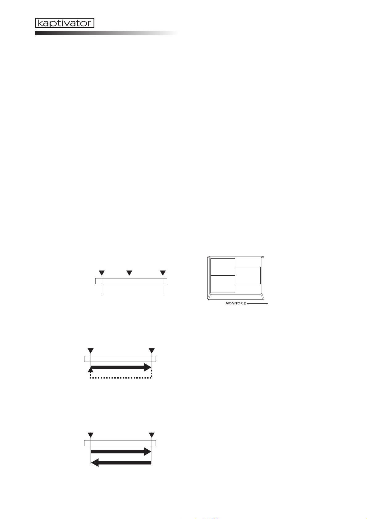
Clip parameter list
Playback Type and Playback Pattern selection
In Clip Edit mode you can choose a playback type and pattern; set the Start, End, Loop and
Index Points; and specify the BPM value. The Start Point will always be the location from
which playback begins, and the End Point will always be where playback either ends, or
returns to the Loop point. In Type 1 and Type 2, the Start Point is used as the Loop Point; In
Types 3 and 4 you are free to set an independent Loop Point. The Index point is used to select
the single frame that will represent the clip when displayed in Bank mode.
When you hold down the EDIT key and press the clip key for the clip you want to edit, the
first thing to appear in the VALUE display will be “T.#. - #.”. The first value (T.1.–T.4) specifies how the playback type, and the second value (-#) specifies the playback pattern.
NOTE Once you’ve specified the pla yback type , y ou won’t be ab le to change this setting unless y ou
exit Clip Edit mode, and begin editing again.
NOTE If you press the Play key while performing clip editing, playback will occur between the Start
Point and End Point you specified. You are free to specify an Index Point that is outside the
range of the Start/End Points.
Type 1: Specified End Point
Patterns of this type will play or loop between the Start Point and End Point. This is the most
basic type of pattern.
Start Point
Index Point
Sampling Data
End Point
Pattern 1: Normal Loop
Start Point End Point
Sampling Data
Pattern 2: Alternating Loop
Start Point End Point
Sampling Data
Start Point
Index Point
End Point
This pattern plays from the Start Point to the End Point,
then returns to the Start Point and continues to play
repeatedly.
This pattern plays from the Start Point to the End Point,
then plays backward toward the Start Point, and continues repeating this action.
40
Page 43

Pattern 3: One-Shot
Start Point End Point
Sampling Data
This pattern plays from the Start Point to the End Point
only once, and then stops (freezes) at the End Point.
Pattern 4: Reverse Normal Loop
Start PointEnd Point
Sampling Data
This pattern is similar to Pattern 1, except the data is
played in reverse. Pattern 4 plays from the Start Point to
the End Point, then returns to the Start Point and continues to play repeatedly.
Pattern 5: Reverse Alternating Loop
End Point Start Point
Sampling Data
This pattern is similar to Pattern 2, except the data is
played in reverse. This pattern plays from the Start
Point to the End Point, then plays back toward the Start
Point, and continues repeating this action.
Owner’s Manual
Pattern 6: Reverse One-Shot
End Point Start Point
Sampling Data
This pattern is similar to Pattern 3, except the data is
played in reverse. This pattern plays from the Start
Point to the End Point only once, and then stops
(freezes) at the End Point.
Type 2: Tempo and Beat Specified End Point
Patterns of this type let you specify the End Point in terms of BPM and a number of beats
(Eb), and are appropriate when you want to synchronize video with music.
For example if you specify the BPM as 120 and the End Beat (number of beats: Eb) value as
8, the End Point will be automatically be placed four seconds (when playing at BPM=120)
later than the Start Point. If you select a style in which the clip playback speed is synchronized to the BPM, and enter the appropriate BPM value, the video loop will play back in synchronization to the beat. The playback patterns are the same as for Type 1.
If you change the Start Point, you’ll need to once again set the BPM value and End Beat setting to re-specify the End Point.
41
Page 44

Type 3: Specified Loop Point and End Point
Patterns of this type allow you to specify a Loop Point separately from the Start Point and
End Point. Playback will loop from this Loop Point.
Start Point
Index Point
Sampling Data
Loop Point
End Point
Pattern 1: Normal
Start Point End PointLoop Point
Sampling Data
Pattern 2: Alternating Loop
Start Point End PointLoop Point
Sampling Data
Start Point
End Point
Loop Point
Index Point
This pattern plays once from the Start Point to the End
Point, and then plays back repeatedly from the Loop
Point.
This pattern plays once to the End Point, and then continues playing alternately forward and backward between the Loop Point and End Point.
42
Pattern 3: Reverse Normal Loop
End Point Start PointLoop Point
Sampling Data
This pattern is similar to Pattern 1, except the data is
played in reverse. This pattern plays once from the Start
Point to the End Point, and then plays back repeatedly
from the Loop Point to the End Point.
Pattern 4: Reverse Alternating Loop
End Point Start PointLoop Point
Sampling Data
This pattern is similar to Pattern 2, except the data is
played in reverse. This pattern plays once to the End
Point, and then continues playing alternately forward
and backward between the Loop Point and End Point.
Page 45

Type 4: Tempo and Beat Specified Loop Point and End Point
Patterns of this type are based on Type 3 which allows you to specify a Loop Point, but differ
in that you can specify the Loop Point and End Point in terms of BPM and number of beats
(Eb). When you specify the BPM and the number of beats (Eb), the End Point will automatically be set to the appropriate time (when playing at that BPM) from the Loop Point. If you
select a style in which the clip playback speed is synchronized to the BPM, and enter the
appropriate BPM value, the video loop will play back in synchronization to the beat. The
playback patterns are the same as for Type 3.
If you change the Start Point, you’ll need to once again set the BPM value and End Beat setting to re-specify the End Point.
Owner’s Manual
43
Page 46

Appendix
Tips for working with the kaptivator
1. Using BPM to control the video playback speed
By using the appropriate BPM setting of a clip together with a BPM-synchronized style, you
can make the video playback speed vary according to the BPM.
➝ With the factory preset styles, style 00 is set to synchronize the video playback speed to
the BPM. Choose style 00, and while you play back the desired clip, tap the TAP/BPM key
in a varying tempo. Notice that the video playback speed will change.
(1) Specifying the BPM value for normal playback
For each clip, specify the BPM value at which the video will play at normal speed. You can
set this BPM value to the tempo of the movement in the video.
1 Hold down the EDIT key and press the clip pad for which you want to specify the BPM.
2Press the EDIT key several times to access the BPM value parameter.
3Press the
video to specify the BPM value. Alternatively, you can use the VALUE knob to specify the
BPM value.
4Press the YES/WRITE key to save the clip settings you edited.
NOTE With the factory settings, the BPM value of all clips is set to “120."
key to play back the clip normally. Tap the TAP/BPM key in time with the
(2) Creating a BPM-synchronized playback style
1 Select the style that you want to edit.
2 Hold down the EDIT key and press the STYLE key.
3Press the EDIT key several times to select parameter C3. (C3 is the parameter that specifies
the normal speed for Group A)
4 Use the VALUE knob to set the value to “r2” so that BPM-synchronized playback will oc-
cur. If you also want to perform BPM-synchronized playback for Group B, press the EDIT
several times to select the parameter E3, and use the VALUE knob to set the value to “r2.”
5Press the YES/WRITE key to save your changes and exit Style Edit.
(3) Playing in sync with the BPM
1 Select the BPM-synchronized style you edited.
2 Specify a BPM value and play back the clip.
3Tap the TAP/BPM key in time with the music.
4 The video playback speed will change in sync with the BPM value.
2. Using the kaptivator with your computer
If you want to use your computer to capture the video from the kaptivator, or use the
kaptivator to sample original video material from your computer, you can connect the
kaptivator’s DV connector to your computer ’s IEEE 1394 connector and enjoy an even wider
range of possibilities.
44
Sending the kaptivator’s main video output to your computer
1Turn on the kaptivator and set the DV connector setting to “out.” (☞p.9)
2 Start up your computer.
3 Connect the kaptivator’s DV port to your computer.
Page 47

4Make sure that the connection has been detected by your computer.
5 Start up your video editing application program on your computer.
6 Begin playback on the kaptivator, and simultaneously start capturing on your video edit-
ing application.
Sampling video from your computer into the kaptivator
1Turn on the kaptivator and set the DV connector setting to “in.” (☞p.9)
2 Start up your computer.
3 Connect your computer to the kaptivator’s DV port.
4Make sure that the connection has been detected by your computer.
5 Start up your video editing application program on your computer.
6 In your video editing application, prepare the video material that you want to send.
7 Set MONITOR 2 on the kaptivator to DV, and begin trial playback via the DV connection to
verify that the kaptivator is receiving the video.
8 Begin sampling on the kaptivator, and immediately start sending the video from your com-
puter.
You’ll have to manually execute playback and sampling on the kaptivator.
NOTE The kaptivator does not support the AV/C commands that automatically control typical DV
devices such as digital video cameras. This means that depending on the application software
you’re using on your computer, error messages may appear in response to operation commands that the kaptivator does not support (such as REC/STOP).
NOTE For details on how to oper ate your video editing application softw are, contact the manuf acturer
of your software.
3. Managing data on the hard drive
You can make efficient use of the internal hard drive’s recording capacity by taking advantage of the clip copy and clip edit functions.
The video material that is sampled into the kaptivator is stored in minimum units of approximately 8 seconds.
For example if you sample four segments of video, which are respectively (a) 3 seconds, (b)
4 seconds, (c) 5 seconds, and (d) 10 seconds long (totaling 22 seconds), the video material
used by these four clips (if sampled individually) would actually occupy (a) 8 seconds, (b)
8 seconds, (c) 8 seconds, and (d) 16 seconds (totaling 40 seconds) of space on the hard disk.
If you used your video editing software etc. to connect these four segments of video into a
single segment with a few blank frames between them, and sample it as a single clip, this
would occupy only 24 seconds of space on the hard disk. Then you would simply copy this
24-second clip to make four clones, and use clip editing to specify the appropriate playback
points for each clip so that they would play back just as if you had sampled them separately.
Owner’s Manual
45
Page 48

4. Using MIDI to work with clips
What is MIDI?
MIDI stands for Musical Instrument Digital Interface, and is a world-wide standard for
transferring a wide variety of performance-related information between electronic musical
instruments and computers.
MIDI connections
Use commercially available MIDI cables to send and receive MIDI messages. Connect the
kaptivator’s MIDI connectors to the MIDI connectors of the external MIDI device.
MIDI IN connector: Receives MIDI messages from another MIDI device. Connect this to the
MIDI OUT connector of your external device.
MIDI OUT connector: Transmits MIDI messages from the kaptivator. Connect this to the
MIDI IN connector of your external device.
MIDI output when you press a Clip Pad
The following note numbers are assigned to the clip pads. The corre-
sponding Note-on message is transmitted when you press a clip pad.
A
64 65 66
60
B
56
61 62
Using a MIDI keyboard to play clips
You can use Note messages sent from a MIDI keyboard connected to the MIDI IN connec-
tor not only to play back the clips selected for the clip pad, but also to play back as many clips
as there are keys on your keyboard, without having to switch banks.
How Note messages correspond to Clips
Upper (note numbers: 64–127)
The clips of the eight banks assigned to clip pad Group A (64 clips) are assigned to note
numbers 64 through 127 in ascending order.
Lower (note numbers: 0–63)
The clips of the eight banks assigned to clip pad Group B (64 clips) are assigned to note
numbers 63 through 0 in descending order.
Bank m
Bank nBank n-1Bank n-2Bank n-6Bank n-7
Bank m+1 Bank m+2 Bank m+6 Bank m+7
7168 69 70
67
63
5957 58
46
A
64 65 66
60
B
56
61 62
56 7247
48 55
7168 69 70
Bank m
67
63
Bank n
5957 58
63
71 79
64
Page 49

Trobleshooting
Power does not turn on.
❐ Is the AC adapter connected?
❐ Is the AC adapter connected to an AC outlet?
The image from the connected device is not input.
❐ Is the cable correctly connected to the connector?
❐ Is your external device powered-on, and is it set correctly?
❐ Have you chosen the correct input setting for the kaptivator?
Image does not appear in the monitor.
❐ Is the external device powered-on, and it is set correctly?
❐ Have you chosen the correct input setting for the kaptivator?
❐ Is MONITOR SELECT set correctly?
❐ If there is a problem with the display, try adjusting the monitor. (☞p.12)
Clip does not play back.
❐ Is the style setting correct?
❐ Could you have selected a style in which playback is synchronized to an audio trigger, or
in which the ribbon controller adjusts the playback speed?
Owner’s Manual
Can’t delete or edit a clip.
❐ Could the clip protect setting be “On”? (☞p.24)
❐ Is a motion sequence running? (☞p.17)
Can’t control via MIDI.
❐ Is the MIDI cable connected correctly?
❐ Have you made settings so that the Kaptivator is transmitting and receiving MIDI data on
the same MIDI channel as the external device?
❐ Is the MIDI channel set correctly? (☞p.27)
47
Page 50

Preset Style list
Style numbers: 00–39 Demo styles (ideas for style settings).
Style numbers: 40–54 Routing variations. Variations of video effects.
Style numbers: 55–84 Wipe variations. Variations of video effects.
Style number: 85 Use the FX control knob to change the dissolve time.
Use the ribbon to change the playback speed.
Group A has smoothing; Group B has no smoothing.
Style number: 86 Use the FX control knob to change the dissolve time.
Use BPM to change the playback speed.
Style numbers: 87–91 Clip Start variations.
Style numbers: 92–97 Time Effect variations.
Use the ribbon to control the playback speed.
Specifications
Video sampling rate: 13.5 MHz, 4:2:2 8-bit
Input/output connectors: VIDEO INPUT 1: Composite
VIDEO INPUT 2: S-Video
AUDIO TRIG INPUT (L, R): RCA connector
MAIN OUT: Composite, S-Video (one each)
MONITOR OUT 1: Composite
MONITOR OUT 2: Composite
PHONES: Stereo 1/4"
DV I/O (digital Video input/output)
MIDI: MIDI IN, MIDI OUT
DC 12V IN
Storage device: 40 GB hard disk
Power supply: DC 12V (dedicated AC adapter)
Dimensions: 310 (W) x 249 (D) x 99 (H) mm
12.20 (W) x 9.80 (D) x 3.90 (H) inches
Weight: 2.8 kg / 6.171 lbs.
Included items: Dedicated AC adapter
* Appearance and specifications are subject to change without notice.
48
Page 51

Style Cheat
Preset
A1 A2 A3 A4 A5 A6 A7 A8
23
Dual
00
FadeF1Slider00range
B1 B2 B3 B4 B5 B6 B7
05
Color ChangeD1HOLDC1Ribbon touch00EitherG1Rebbon ValueH1Knob
Group A Operation settings
C1 C2 C3 C4 D1 D2 D3 D4 D5 D6
T1
Start when
pressed
E1
Ext value
r2
BPM00Enabled05Reverse: x1b1Beat
Group B Operation settings
E1 E2 E3 E4 F1 F2 F3 F4 F5 F6
--
Same as
GroupA
Controller default value settings
G1 G2 G3 G4 G5 H1 H2 H3
--
Unspecified--Unspecified
--
Unspecified--Unspecified--Unspecified00BANK
Routing settings RemarksStyle No.
Video Effect settings
Group A Time Effect settings
Group B Time Effect settings
Monitor selection settings
A1
Audio99Both
00
ALL
b1
Beat50Fixed value
The slider fades between group
A and group B.
Video effect is applied after
mixing.
Playback speed changes in
relative fashion in
synchronization to the BPM
value.
Playback speed and direction
switch in synchronization with
the beat of the audio input.
A1 A2 A3 A4 A5 A6 A7 A8
Routing settings RemarksStyle No.
23
Dual
00
FadeF1Slider00range
Video Effect settings
B1 B2 B3 B4 B5 B6 B7
02
Rotate 180A1Audio99Always On00Either
Group A Operation settings
A1
Audio
Group A Time Effect settings
C1 C2 C3 C4 D1 D2 D3 D4 D5 D6
T1
Start when
pressed
E1
Ext value
Group B Operation settings
r1
x100Enabled00ScratchD1HOLDC1Ribbon Touch00EitherG1Ribbon valueH1Knob
Group B Time Effect settings
E1 E2 E3 E4 F1 F2 F3 F4 F5 F6
--
Same as
GroupA
Controller default value settings
Monitor selection settings
G1 G2 G3 G4 G5 H1 H2 H3
--
Unspecified--Unspecified
--
Unspecified--Unspecified--Unspecified00BANK
00
ALL
Routing settings RemarksStyle No.
A1 A2 A3 A4 A5 A6 A7 A8
23
Dual
00
FadeF1Slider00range
Video Effect settings
B1 B2 B3 B4 B5 B6 B7
11
BlurA1Audio00Always Off00Either
Group A Operation settings
A1
Audio
Group A Time Effect settings
C1 C2 C3 C4 D1 D2 D3 D4 D5 D6
T1
Start when
pressed
E1
Ext value
Group B Operation settings
r1
x100Enabled01R:S:FD1HOLDC1Ribbon Touch00EitherG1Ribbon valueH1Knob
Group B Time Effect settings
E1 E2 E3 E4 F1 F2 F3 F4 F5 F6
--
Same as
GroupA
Controller default value settings
Monitor selection settings
G1 G2 G3 G4 G5 H1 H2 H3
--
Unspecified--Unspecified
--
Unspecified--Unspecified--Unspecified00BANK
00
ALL
Fade-mix between A and B.
The video effect is applied after
mixing. Audio triggering will
rotate the video image 180
degrees. Use the ribbon
controller to scratch.
Fade-mix between A and B.
The video effect is applied after
mixing. Audio triggering will
apply a blur effect to the video.
Use the ribbon controller to
control reverse, freeze, and
forward playback of the image.
Style Cheat
93
Page 52

A1 A2 A3 A4 A5 A6 A7 A8
Routing settings RemarksStyle No.
23
Dual
00
FadeF1Slider00range
Video Effect settings
B1 B2 B3 B4 B5 B6 B7
06
RGB
Separation
Group A Operation settings
D1
HOLDC1Ribbon touch00EitherG1Ribbon valueH1Knob
Group A Time Effect settings
C1 C2 C3 C4 D1 D2 D3 D4 D5 D6
T1
Start when
pressed
E1
Ext value
Group B Operation settings
r2
BPM00Enabled04x1:FwdA1Audio99Always On99Fixed valueA1Audio50Fixed value
Group B Time Effect settings
E1 E2 E3 E4 F1 F2 F3 F4 F5 F6
--
Same as
GroupA
Controller default value settings
Monitor selection settings
G1 G2 G3 G4 G5 H1 H2 H3
--
Unspecified--Unspecified
--
Unspecified--Unspecified--Unspecified00BANK00ALL
Fade-mix between A and B.
The video effect is applied after
mixing. Operating the ribbon
controller will apply a video
effect that separates the image
into RGB. The image playback
speed will change in
synchronization with the BPM
value.
A1 A2 A3 A4 A5 A6 A7 A8
Routing settings RemarksStyle No.
23
Dual
00
FadeF1Slider00range
Video Effect settings
B1 B2 B3 B4 B5 B6 B7
07
EmbossD1HOLDC1Ribbon touch00EitherG1Ribbon valueH1Knob
Group A Operation settings
Group A Time Effect settings
C1 C2 C3 C4 D1 D2 D3 D4 D5 D6
T1
Start when
pressed
E1
Ext value
Group B Operation settings
r2
BPM00Enabled05Reverse : x1A1Audio99Always On99Fixed valueA1Audio50Fixed value
Group B Time Effect settings
E1 E2 E3 E4 F1 F2 F3 F4 F5 F6
--
Same as
GroupA
Controller default value settings
Monitor selection settings
G1 G2 G3 G4 G5 H1 H2 H3
--
Unspecified--Unspecified
--
Unspecified--Unspecified--Unspecified00BANK00ALL
Routing settings RemarksStyle No.
A1 A2 A3 A4 A5 A6 A7 A8
23
Dual
00
Fade
B1
BeatF2Slider
Video Effect settings
B1 B2 B3 B4 B5 B6 B7
11
BlurD1HOLDC1Ribbon touch00EitherG1Ribbon valueH1Knob
Group A Operation settings
Group A Time Effect settings
C1 C2 C3 C4 D1 D2 D3 D4 D5 D6
T1
Start when
pressed
E1
Ext value
Group B Operation settings
B2
Beat00Enabled05Reverse : x1A1Audio99Always On99Fixed valueA1Audio50Fixed value
Group B Time Effect settings
E1 E2 E3 E4 F1 F2 F3 F4 F5 F6
--
Same as
GroupA
Controller default value settings
Monitor selection settings
G1 G2 G3 G4 G5 H1 H2 H3
--
Unspecified--Unspecified
--
Unspecified--Unspecified--Unspecified00BANK00ALL
Fade-mix between A and B.
The video effect is applied after
mixing. Operating the ribbon
controller will apply an emboss
effect. The image playback
speed will change in
synchronization with the BPM
value. Audio triggering will
reverse the playback.
Switch between A and B
according to the beat. Use the
slider to adjust the mixing
amount. The video effect is
applied after mixing. Operating
the ribbon controller will apply a
blur effect. Audio triggering will
reverse the playback.
94
Page 53

A1 A2 A3 A4 A5 A6 A7 A8
Routing settings RemarksStyle No.
21
Dual
00
FadeF1Slider00range
Video Effect settings
B1 B2 B3 B4 B5 B6 B7
07
EmbossD1HOLDC1Ribbon touch00EitherG1Ribbon valueH1Knob
Group A Operation settings
Group A Time Effect settings
C1 C2 C3 C4 D1 D2 D3 D4 D5 D6
T4
Pause when
released
E1
Ext value
Group B Operation settings
r1
x100Enabled
Off
--
Group B Time Effect settings
E1 E2 E3 E4 F1 F2 F3 F4 F5 F6
The clip will play while you hold
down the clip pad, and will stop
when you release the pad. A
and B will be fade-mixed. The
video effect is applied only to
the group A image. Operating
the ribbon controller will apply
an emboss effect to the video.
Controller default value settings
Monitor selection settings
G1 G2 G3 G4 G5 H1 H2 H3
--
Unspecified--Unspecified
--
Unspecified--Unspecified--Unspecified00BANK
00
ALL
Routing settings RemarksStyle No.
A1 A2 A3 A4 A5 A6 A7 A8
23
Dual
00
FadeF1Slider99range
Video Effect settings
B1 B2 B3 B4 B5 B6 B7
14
Binarize99Audio99Always On00Either
Group A Operation settings
F4
Audio
Group A Time Effect settings
00
Fixed Value99Fixed Value
C1 C2 C3 C4 D1 D2 D3 D4 D5 D6
T1
Start when
pressed
E1
Ext value
Group B Operation settings
r1
x100Enabled
00
Invert top
/bottom
D1
HOLDC1Ribbon Touch00EitherG1Ribbon valueH1Knob
Group B Time Effect settings
E1 E2 E3 E4 F1 F2 F3 F4 F5 F6
--
Same as
GroupA
Controller default value settings
Monitor selection settings
G1 G2 G3 G4 G5 H1 H2 H3
--
Unspecified--Unspecified
--
Unspecified--Unspecified--Unspecified00BANK
00
ALL
Routing settings RemarksStyle No.
A1 A2 A3 A4 A5 A6 A7 A8
13
Single00FadeF1Slider00range
Video Effect settings
B1 B2 B3 B4 B5 B6 B7
06
BlurD1HOLDC1Ribbon touch00EitherG1Ribbon valueH1Knob
Group A Operation settings
Group A Time Effect settings
C1 C2 C3 C4 D1 D2 D3 D4 D5 D6
T1
Start when
pressed
E1
Ext value
Group B Operation settings
r2
BPM00Enabled04x1:FwdA1Audio99Always On99Fixed valueA1Audio50Fixed value
Group B Time Effect settings
E1 E2 E3 E4 F1 F2 F3 F4 F5 F6
--
Same as
GroupA
Controller default value settings
Monitor selection settings
G1 G2 G3 G4 G5 H1 H2 H3
--
Unspecified--Unspecified
--
Unspecified--Unspecified--Unspecified00BANK
00
ALL
Switch between A and B. Blackout (black screen) with the
slider in the center position. The
setting uses the video effect to
black-out. You can change this
to white-out by changing the B7
setting to “00.”
Fade-mix between clips A/B
and the external input video.
The video effect is applied after
mixing. Audio triggering will
change the speed of the clip.
Style Cheat
95
Page 54

User
A1 A2 A3 A4 A5 A6 A7 A8
B1 B2 B3 B4 B5 B6 B7
Group A Operation settings
C1 C2 C3 C4 D1 D2 D3 D4 D5 D6
Group B Operation settings
E1 E2 E3 E4 F1 F2 F3 F4 F5 F6
Controller default value settings
G1 G2 G3 G4 G5 H1 H2 H3
A1 A2 A3 A4 A5 A6 A7 A8
B1 B2 B3 B4 B5 B6 B7
Routing settings RemarksStyle No.
Video Effect settings
Group A Time Effect settings
Group B Time Effect settings
Monitor selection settings
Routing settings RemarksStyle No.
Video Effect settings
Group A Operation settings
C1 C2 C3 C4 D1 D2 D3 D4 D5 D6
Group B Operation settings
E1 E2 E3 E4 F1 F2 F3 F4 F5 F6
Controller default value settings
G1 G2 G3 G4 G5 H1 H2 H3
A1 A2 A3 A4 A5 A6 A7 A8
Video Effect settings
B1 B2 B3 B4 B5 B6 B7
Group A Operation settings
C1 C2 C3 C4 D1 D2 D3 D4 D5 D6
Group B Operation settings
E1 E2 E3 E4 F1 F2 F3 F4 F5 F6
Group A Time Effect settings
Group B Time Effect settings
Monitor selection settings
Routing settings RemarksStyle No.
Group A Time Effect settings
Group B Time Effect settings
96
G1 G2 G3 G4 G5 H1 H2 H3
Controller default value settings
Monitor selection settings
Page 55

KTV1 MIDI IMPLEMENTATION
1.TRANSMITTED DATA
1-1 CHANNEL MESSAGES [H]:Hex, [D]:Decimal
+--------+--------+--------+---------------------+---+
| Status | Second | Third | Description |ENA|
| [Hex] | [H] [D]| [H] [D]| | |
+--------+--------+--------+---------------------+---+
| 8n | kk (kk)| 40 (64)| Note Off | A |
| 9n | kk (kk)| 40 (64)| Note On | A |
| Bn | cc (cc)| dd (dd)| Control Change | C |
| Cn | pp (pp)| -- -- | Program Change | P |
| En | bb (bb)| bb (bb)| Bender Change | C |
+--------+--------+--------+---------------------+---+
ENA = A : Transmit when Note On/Off Enable.
C : Transmit when Control Change Enable.
P : Transmit when Program Change Enable.
nn : MIDI Channel No,(0~15) Usually Global Channel.
kk : Note Number (48~71)
cc : Control Number (1~31,64~95)
dd : Control Data (0~127)
pp : Program Number (0~99)
bb : Pitch Bender Data (0~16383)
1-2 SYSTEM REALTIME MESSAGES
+------------+---------------------------------------+
| Status[Hex]| Description ( Transmitted when ... ) |
+------------+---------------------------------------+
| F8 | Timing Clock ( Clock Out ) |
| FE | Active Sensing ( Always ) |
+------------+---------------------------------------+
1-3 UNIVERSAL SYSTEM EXCLUSIVE MESSAGES (DEVICE INQUIRY REPLAY)
+------------+---------------------------------------+
| Byte [Hex] | Description |
+------------+---------------------------------------+
| F0 | Exclusive Status |
| 7E | Non Realtime Message |
| 0n | MIDI Channel Number (Device ID) |
| 06 | Inquiry Message (Sub ID 1) |
| 02 | Identity Reply (Sub ID 2) |
| 42 | KORG ID (Manufactures ID)|
| 77 | KTV1 ID (Family ID (LSB))|
| 00 | ( (MSB))|
| 00 | (Member ID (LSB))|
| 00 | ( (MSB))|
| ** | ROM No, 1~ (Minor Ver.(LSB))|
| 00 | ( (MSB))|
| ** | Soft Version (Major Ver.(LSB))|
| 00 | ( (MSB))|
| F7 | EOX |
+------------+---------------------------------------+
This message is transmitted whenever a INQUIRY MESSAGE REQUEST is received.
1-4 STRUCTURE OF SYSTEM EXCLUSIVE MESSAGES
+- -+
| 1st Byte = 1111 0000 (F0) : Exclucive Status -+ |
| 2nd Byte = 0100 0010 (42) : KORG ID | Ex.Header |
| 3rd Byte = 0011 nnnn (3n) : Format ID n:MIDI Channel | |
| 4th Byte = 0111 0111 (77) : KTV1 ID -+ |
| 5th Byte = 0fff ffff (ff) : Function Code |
| 6th Byte = 0ddd dddd (dd) : Data |
| : : : |
| LastByte = 1111 0111 (F7) : End of Exclusive |
+- -+
1-5 SYSTEM EXCLUSIVE MESSAGES FUNCTION CODE LIST (TRANSMIT)
+-------------------+------------------------------+---+---+
| Function ID [Hex] | Description | R | E |
+-------------------+------------------------------+---+---+
| 51 | Global Data Dump | o | |
| 65 | All Style Data Dump | o | |
| 79 | 1 Motion Sequence Data Dump | o | |
| 7B | 10 Motion Sequence Data Dump | o | |
| 23 | Data Process(Load) Completed | | o |
| 24 | Data Process(Load) Error | | o |
+-------------------+------------------------------+---+---+
Transmitted when
R : Request message is received and data dump from MIDI dump page.
E : Exclusive message received.
2.RECOGNIZED RECEIVE DATA
2-1 CHANNEL MESSAGE
+--------+--------+--------+---------------------+---+
| Status | Second | Third | Description |ENA|
| [Hex] | [H] [D]| [H] [D]| | |
+--------+--------+--------+---------------------+---+
| 8n | kk (kk)| vv (vv)| Note Off | A |
| 9n | kk (kk)| 00 (00)| Note off | A |
| 9n | kk (kk)| vv (vv)| Note On | A |
| Bn | cc (cc)| dd (dd)| Control Change | C |
| Cn | pp (pp)| -- -- | Program Change | P |
| En | bb (bb)| bb (bb)| Bender Change | C |
+--------+--------+--------+---------------------+---+
ENA = A : Recognized when Note On/Off Enable
C : Recognized when Control Change Enable
P : Recognized when Program Change Enable
nn : MIDI Channel No,(0~15) Usually Global Channel.
kk : Note Number (48~71)
vv : Verocity will be ignored
cc : Control Number (1~31,64~95)
dd : Control Data (0~127)
pp : Program Number (0~99)
bb : Pitch Bender Data (0~16383)
2-2 SYSTEM REALTIME MESSAGES
+------------+---------------------------------------+
| Status[Hex]| Description ( Recognized when ... ) |
+------------+---------------------------------------+
| F8 | Timing Clock ( Clock Ext.In ) |
| FE | Active Sensing ( Always ) |
+------------+---------------------------------------+
2-3 UNIVERSAL SYSTEM EXCLUSIVE MESSAGE (DEVICE IMQUIRY REQUEST)
+------------+---------------------------------------+
| Byte [Hex] | Description |
+------------+---------------------------------------+
| F0 | Exclusive Status |
| 7E | Non Realtime Message |
| nn | MIDI Channel Number (Device ID) |
| 06 | Inquiry Message (Sub ID 1) |
| 01 | Identity Request (Sub ID 2) |
| F7 | EOX |
+------------+---------------------------------------+
When receive this message and transmits Inquiry Reply Message.
nn = 00~0F : Receive if same Chammel
7F : Receive any Channel
2-4 SYSTEM EXCLUSIVE MESSAGE FUNCTION CODE LIST (RECEIVE)
+-------------------+--------------------------------------+
| Function ID [Hex] | Description |
+-------------------+--------------------------------------+
| 0E | Global Data Dump Request |
| 31 | All Style Data Dump Request |
| 78 | 1 Motion Sequence Data Dump Request |
| 7A | 10 Motion Sequence Data Dump Request |
| 51 | Global Data Dump |
| 65 | All Style Data Dump |
| 79 | 1 Motion Sequence Data Dump |
| 7B | 10 Motion Sequence Data Dump |
+-------------------+--------------------------------------+
Recognized only on the MIDI dump page.
3.MIDI EXCLUSIVE FORMAT (R:Receive, T:Transmit)
(1) GLOBAL DATA DUMP REQUEST R
+----------------+------------------------------------------------+
| Byte [Hex] | Description |
+----------------+------------------------------------------------+
| F0,42,3n,77 | Exclusive Header KTV1 |
| 0000 1110 (0E) | Global Data Dump Request 0Eh |
| 1111 0111 (F7) | EOX |
+----------------+------------------------------------------------+
When this message is received at the MIDI dump page, the GLOBAL DATA
DUMP(Function:51h) message will be transmitted.
The DATA PROCESS(LOAD) ERROR(Function:24h) message will be transmitted
in other cases.
(2) ALL STYLE DATA DUMP REQUEST R
+----------------+------------------------------------------------+
| Byte [Hex] | Description |
+----------------+------------------------------------------------+
| F0,42,3n,77 | Exclusive Header KTV1 |
| 0011 0001 (31) | All Style Data Dump Request 31h |
| 1111 0111 (F7) | EOX |
+----------------+------------------------------------------------+
When this message is received at the MIDI dump page, the GLOBAL DATA
DUMP(Function:65h) message will be transmitted.
The DATA PROCESS(LOAD) ERROR(Function:24h) message will be transmitted
in other cases.
MIDI Implementation
97
Page 56

(3) 1 MOTION SEQUENCE DATA DUMP REQUEST R
+----------------+------------------------------------------------+
| Byte [Hex] | Description |
+----------------+------------------------------------------------+
| F0,42,3n,77 | Exclusive Header KTV1 |
| 0111 1000 (78) | 1 Motion Sequence Data Dump Request 78h |
| 0mmm mmmm (mm) | Dump Motion Number (mm = 00h~63h) |
| 1111 0111 (F7) | EOX |
+----------------+------------------------------------------------+
When this message is received at the MIDI dump page, the 1 MOTION
SEQUENCE DATA DUMP(Function:79h) message will be transmitted.
The DATA PROCESS(LOAD) ERROR(Function:24h) message will be transmitted
in other cases.
(4) 10 MOTION SEQUENCE DATA DUMP REQUEST R
+----------------+------------------------------------------------+
| Byte [Hex] | Description |
+----------------+------------------------------------------------+
| F0,42,3n,77 | Exclusive Header KTV1 |
| 0111 1010 (7A) | 10 Motion Sequence Data Dump Request 7Ah |
| 0000 pppp (0p) | Dump Motion Page Number (0p = 00h~09h) |
| 1111 0111 (F7) | EOX |
+----------------+------------------------------------------------+
When this message is received at the MIDI dump page, the 10 MOTION
SEQUENCE DATA DUMP(Function:7Bh) message will be transmitted.
The DATA PROCESS(LOAD) ERROR(Function:24h) message will be transmitted
in other cases.
(5) GLOBAL DATA DUMP R/T
+----------------+------------------------------------------------+
| Byte [Hex] | Description |
+----------------+------------------------------------------------+
| F0,42,3n,77 | Exclusive Header KTV1 |
| 0101 0001 (51) | Global Data Dump 51h |
| 0ddd dddd (dd) | Data [NOTE1][TABLE1]|
| : | : |
| 1111 0111 (F7) | EOX |
+----------------+------------------------------------------------+
When this message is received at the MIDI dump page, the DATA PROCESS
(LOAD) COMPLETED(Function:23h) message or the DATA PROCESS(LOAD) ERROR
(Function:24h) message will be transmitted.
The DATA PROCESS(LOAD) ERROR(Function:24h) message will be transmitted
in other cases.
(6) ALL STYLE DATA DUMP R/T
+----------------+------------------------------------------------+
| Byte [Hex] | Description |
+----------------+------------------------------------------------+
| F0,42,3n,77 | Exclusive Header KTV1 |
| 0110 0101 (65) | All Style Data Dump 65h |
| 0ddd dddd (dd) | Data [NOTE2][TABLE2]|
| : | : |
| 1111 0111 (F7) | EOX |
+----------------+------------------------------------------------+
When this message is received at the MIDI dump page, the DATA PROCESS
(LOAD) COMPLETED(Function:23h) message or the DATA PROCESS(LOAD) ERROR
(Function:24h) message will be transmitted.
The DATA PROCESS(LOAD) ERROR(Function:24h) message will be transmitted
in other cases.
(7) 1 MOTION SEQUENCE DATA DUMP R/T
+----------------+------------------------------------------------+
| Byte [Hex] | Description |
+----------------+------------------------------------------------+
| F0,42,3n,77 | Exclusive Header KTV1 |
| 0111 1001 (79) | 1 Motion Sequence Data Dump 79h |
| 0mmm mmmm (mm) | Dump Motion Number (mm = 00h~63h) |
| 0ddd dddd (dd) | Data [NOTE3][TABLE3]|
| : | : |
| 1111 0111 (F7) | EOX |
+----------------+------------------------------------------------+
When this message is received at the MIDI dump page, the DATA PROCESS
(LOAD) COMPLETED(Function:23h) message or the DATA PROCESS(LOAD) ERROR
(Function:24h) message will be transmitted.
The DATA PROCESS(LOAD) ERROR(Function:24h) message will be transmitted
in other cases.
(8) 10 MOTION SEQUENCE DATA DUMP R/T
+----------------+------------------------------------------------+
| Byte [Hex] | Description |
+----------------+------------------------------------------------+
| F0,42,3n,77 | Exclusive Header KTV1 |
| 0111 1011 (7B) | 10 Motion Sequence Data Dump 7Bh |
| 0000 pppp (0p) | Dump Motion Page Number (0p = 00h~09h) |
| 0ddd dddd (dd) | Data [NOTE4][TABLE3]|
| : | : |
| 1111 0111 (F7) | EOX |
+----------------+------------------------------------------------+
When this message is received at the MIDI dump page, the DATA PROCESS
(LOAD) COMPLETED(Function:23h) message or the DATA PROCESS(LOAD) ERROR
(Function:24h) message will be transmitted.
The DATA PROCESS(LOAD) ERROR(Function:24h) message will be transmitted
in other cases.
(9) DATA PROCESS(LOAD) COMPLETED T
+----------------+------------------------------------------------+
| Byte [Hex] | Description |
+----------------+------------------------------------------------+
| F0,42,3n,77 | Exclusive Header KTV1 |
| 0010 0011 (23) | DATA PROCESS(LOAD) COMPLETED 23h |
| 1111 0111 (F7) | EOX |
+----------------+------------------------------------------------+
Transmits this message when DATA LOAD, PROCESSING have been completed.
(10) DATA PROCESS(LOAD) ERROR T
+----------------+------------------------------------------------+
| Byte [Hex] | Description |
+----------------+------------------------------------------------+
| F0,42,3n,77 | Exclusive Header KTV1 |
| 0010 0100 (24) | DATA PROCESS(LOAD) COMPLETED 24h |
| 1111 0111 (F7) | EOX |
+----------------+------------------------------------------------+
Transmits this message when DATA LOAD, PROCESSING have not been completed.
Dump Data Format
n = 0, 1, ...
DATA ( 1set = 8bit x 7byte )
b7 ~ b0 b7 ~ b0 b7 ~~ b0 b7 ~ b0
+-+-+-+-+-+-+-+-+ +-+-+-+-+-+-+-+-+ +-+-+-~~-+-+-+ +-+-+-+-+-+-+-+-+
| | | | | | | | | | | | | | | | | | | | | | | | | | | | | | | | |
+-+-+-+-+-+-+-+-+ +-+-+-+-+-+-+-+-+ +-+-+-~~-+-+-+ +-+-+-+-+-+-+-+-+
7n+0 7n+1 7n+2 ~~ 7n+5 7n+6
MIDI DATA ( 1set = 7bit x 8Byte )
b7b7b7b7b7b7b7 b6 ~ b0 b6 ~~ b0 b6 ~ b0
+-+-+-+-+-+-+-+-+ +-+-+-+-+-+-+-+-+ +-+-+-~~-+-+-+ +-+-+-+-+-+-+-+-+
|0| | | | | | | | |0| | | | | | | | |0| | | | | |0| | | | | | | |
+-+-+-+-+-+-+-+-+ +-+-+-+-+-+-+-+-+ +-+-+-~~-+-+-+ +-+-+-+-+-+-+-+-+
7n+6,5,4,3,2,1,0 7n+0 7n+1 ~~ 7n+5 7n+6
NOTE 1 : GROBAL DATA DUMP FORMAT
[Global Data (22byte)] (see TABLE 1)
22byte = 7 * 3 + 1 --> 8 * 3 + (1 + 1) = 26byte
NOTE 2 : ALL STYLE DATA DUMP FORMAT
[Style.00(32byte)], ... ,[Style.99(32byte)] (see TABLE 2)
3200byte = 7 * 457 + 1 --> 8 * 457 + (1 + 1) = 3658byte
NOTE 3 : 1 MOTION SEQUENCE DATA DUMP FORMAT
[Motion Data (16~200048byte)] (see TABLE 3)
16byte = 7 * 2 + 2 --> 8 * 2 + (2 + 1) = 19byte
200048byte = 7 * 28578 + 2 --> 8 * 28578 + (2 + 1) = 228627byte
NOTE 4 : 10 MOTION SEQUENCE DATA DUMP FORMAT
[Motion Data p0(16~200048byte)],
... ,[Motion Data p9(16~200048byte] (see TABLE 3)
160byte = 7 * 22 + 6 --> 8 * 22 + (6 + 1) = 183byte
2000480byte = 7 * 285782 + 6 --> 8 * 285782 + (6 + 1) = 2286263byte
TABLE 1 :
+0 Monitor 1 Bright (valid:0~140)
+1 Monitor 1 Contrast (valid:0~181)
+2 Monitor 1 Color (valid:0~255)
+3 Monitor 2 Bright (valid:0~140)
+4 Monitor 2 Contrast (valid:0~181)
+5 Monitor 2 Color (valid:0~255)
+6 DV Direction IN/OUT (0=In, 1=out)
+7 Main Out Capture DIS/ENA (0=Disable, 1=Enable)
+8 Power on Style Number (0~99)
+9 Power on Group A Bank Number (0~99)
+10 Power on Group B Bank Number (0~99)
+11 MIDI Channel (0~15)
+12 bit7 MIDI Ribbon Touch [C] ENA/DIS (0=Enable, 1=Disable)
bit6-0 MIDI Ribbon Touch [C] CTRL#
+13 bit7 MIDI Hold [D] ENA/DIS (0=Enable, 1=Disable)
bit6-0 MIDI Hold [D] CTRL#
+14 bit7 MIDI [E] ENA/DIS (0=Enable, 1=Disable)
bit6-0 MIDI [E] CTRL#
+15 bit7 MIDI Slider [F] ENA/DIS (0=Enable, 1=Disable)
bit6-0 MIDI Slider [F] CTRL#
+16 bit7 MIDI Ribbon [G] ENA/DIS (0=Enable, 1=Disable)
bit6-0 MIDI Ribbon [G] CTRL#
+17 bit7 MIDI Knob [H] ENA/DIS (0=Enable, 1=Disable)
bit6-0 MIDI Knob [H] CTRL#
+18 bit7 MIDI Group A ENA/DIS (0=Enable, 1=Disable)
bit6-0 MIDI Group A CTRL#
+19 bit7 MIDI Group B ENA/DIS (0=Enable, 1=Disable)
bit6-0 MIDI Group B CTRL#
98
Page 57

+20 bit7 MIDI Style Fx ENA/DIS (0=Enable, 1=Disable)
bit6-0 MIDI Style Fx CTRL#
+21 bit7-4 (reserved)
bit3-2 MIDI Clock Out/Ext.In/DIS (01=Ext.In, 10=Out, 11=Disable)
bit1 MIDI Note ENA/DIS (0=Enable, 1=Disable)
bit0 MIDI Program Change ENA/DIS (0=Enable, 1=Disable)
CTRL#
1~31,64~95 : CTRL# 1~31,64~95
96 : Pitch Bender
TABLE 2 :
+0 bit7-6 Transition Type Sub 0~3
bit5-4 Transition Type Main 0~3
bit3-0 Rute Type 0~14
+1 Main Transition Controller CONT#
+2 Main Transition Range/Type 0~99
+3 Sub Transition Controller CONT#
+4 Sub Transition Range/Type 0~99
+5 bit7 Video FX Assign Flag 0~1 (0=Assign, 1=not Assign)
bit6 Video FX Switch Type OR/AND (0=Or, 1=And)
bit5-0 Video FX Program Number 0~15
+6 Video FX Switch 1 CONT#
+7 Video FX Switch 2 CONT#
+8 Video FX Controller 1 CONT#
+9 Video FX Controller 2 CONT#
+10 Video FX Controller 3 CONT#
+11 bit7 (reserved)
bit6 Group A PAD Soft Change ENA/DIS (0=Enable, 1=Disable)
bit5-0 Group A PAD Action Type 0~4
+12 Group A Dissolve Controller CONT#
+13 Group A Normal Playback Speed SPEED#
+14 bit7 Group A Time FX Assign Flag 0~1 (0=Assign, 1=not Assign)
bit6 Group A Time FX Switch Type OR/AND (0=Or, 1=And)
bit5-0 Group A Time FX Number 0~2
+15 Group A Time FX Switch 1 CONT#
+16 Group A Time FX Switch 2 CONT#
+17 Group A Time FX Controller 1 CONT#
+18 Group A Time FX Controller 2 CONT#
+19 bit7 (reserved)
bit6 Group B PAD Soft Change ENA/DIS (0=Enable, 1=Disable)
bit5-0 Group B PAD Action Type 0~4
+20 Group B Dissolve Controller CONT#
+21 Group B Normal Playback Speed SPEED#
+22 bit7 Group B Time FX Assign Flag 0~1 (0=Assign, 1=not Assign)
bit6 Group B Time FX Switch Type OR/AND (0=Or, 1=And)
bit5-0 Group B Time FX Number 0~2
+23 Group B Time FX Switch 1 CONT#
+24 Group B Time FX Switch 2 CONT#
+25 Group B Time FX Controller 1 CONT#
+26 Group B Time FX Controller 2 CONT#
+27 Initial Value [H] INIT#
+28 Initial Value [G] INIT#
+29 Initial Value [F] INIT#
+30 Initial Value [E] INIT#
+31 bit7-6 Initial Value [D] Off/On/-- (0=off,1=on,3=not init.)
bit5-4 Exchange B<->Ext.In DIS/ENA (0=Disable, 1=Enable)
bit3 (reserved)
bit2 Monitor 2 [ALL] by Input sel. ENA/DIS (0=Enable, 1=Disable)
bit1 Monitor 2 [ALL] by Style sel. ENA/DIS (0=Enable, 1=Disable)
bit0 Monitor 2 [BANK] by Bank sel. ENA/DIS (0=Enable, 1=Disable)
CONT#
bit7=0, bit6-0 : Constant Value 0~99
bit7=1, bit6-5 : (reserved) 0
bit4-2 : Controller 0~7
bit1-0 : Type 0~3
SPEED#
bit7=0, bit6-0 : Constant Speed 0~99 (0=stop, ... ,50=x1, ... ,99=x2)
bit7=1, bit6=0, bit5 : (reserved) 0
bit4-2 : Controller 0~7
bit1-0 : Type 0~3
bit7=1, bit6=1, bit5-1 : (reserved) 31
bit0 : Speed 0~1 (0=Normal Speed x1, 1=BPM Sync)
INIT#
bit7=0, bit6-0 : Initialize Value 0~99
bit7=1, bit6-0 : not initilize (127)
TABLE 3 :
+0 Motion Data Type Indicator LSB 03h
+1 Motion Data Type Indicator MSB 01h
Motion Data Type Indicator [0103h]
+2 bit7-1 (reserved)
bit0 Loop Control Once/Loop (0=Once, 1=Loop)
+3 (reserved)
+4 Step Count LSB
+5 Step Count MSB
Step Count 0,4~25004
+6~15 (reserved)
+16~200047 MOTION DATA# (8 * Step Count = 0~200032byte)
(MAX)
MOTION DATA#
+0 Controller [H] (1st,3rd)
Controller [E] (2nd,4th)
+1 Controller [G]
+2 Controller [F]
+3 bit7-2 (reserved)
bit1 Controller [D] Off/On (0=Off, 1=On)
bit0 Controller [C] Off/On (0=Off, 1=On)
+4 Group A Pad On (1st,3rd)
Group A Pad Off (2nd,4th)
+5 Group B Pad On (1st,3rd)
Group B Pad Off (2nd,4th)
+6 Bank A Number (1st,3rd)
Tempo LSB (2nd)
Style Number (4th)
+7 Band B Number (1st,3rd)
Tempo MSB (2nd)
Video FX (4th)
MIDI Implementation
99
Page 58

[
DYNAMIC VIDEO STATION
kaptivator
Function Transmitted Recognized Remarks
]
MIDI Implementation Chart
2005.2.22
Basic
Channel:
Mode
Note
Number:
Velocity:
Aftertouch:
Pitch Bend
Control
Change
Default
Changed
Default
Messages
Altered
True Voice
Note On
Note Off
Key’s
Channel
1– 31, 64–95
121
1–16 1–16
1–16
**************
56–71 0–127
**************
Memorized
1–16
3
0–127
As control source
As control source
Reset All Controllers
Program
Change:
System Exclusive
System
Common:
System
Real Time:
Aux
Messages:
Remarks
Transmitted/received when control numbers or pitch bend are selected,
and are enabled.
Transmitted/received when program changes are enabled.
Transmitted/received when timing clock is enabled.
Mode 1: OMNI ON, POLY Mode 2: OMNI ON, MONO : Yes
Mode 3: OMNI OFF, POLY Mode 4: OMNI OFF, MONO : No
Variable Range
Song Position
Song Select
Tune Request
Clock
Commands
Local On/Off
All Notes Off
Active Sensing
System Reset
0–99
**************
0–99
0–99
Dump mode only
Page 59

IMPORTANT NOTICE TO CONSUMERS
This product has been manufactured according to strict specifications and voltage requirements that
are applicable in the country in which it is intended that this product should be used. If you have
purchased this product via the internet, through mail order, and/or via a telephone sale, you must
verify that this product is intended to be used in the country in which you reside.
WARNING: Use of this product in any country other than that for which it is intended could be
dangerous and could invalidate the manufacturer's or distributor's warranty.
Please also retain your receipt as proof of purchase otherwise your product may be disqualified from
the manufacturer's or distributor's warranty.
4015-2 Yanokuchi, Inagi-city, Tokyo 206-0812 Japan
2005 KORG INC.
1605 GTH
Printed in Japan
 Loading...