

Page 1
Parameter Guide
1E
Page 2

About this manual
The manuals and how to use them
The KROSS comes with the following manuals.
• Quick Start Guide (printed)
The manuals listed below can be downloaded from the Korg
website.
• Operation Guide (PDF)
• Parameter Guide (PDF) (this document)
• Voice Name List (PDF)
You can also watch video manuals on the Korg website.
• Video manual
http://www.korg.co.jp/English/Distributors/ or
http://www.korg.com/
Quick Start Guide
This provides a simple explanation of the KROSS’s
functions. To begin, please read the Quick Start Guide.
Video Manual
This video illustrates the main functionality of the KROSS.
Operation Guide
Put simply, the Operation Guide is designed to answer the
question, “How do I do this?”
It explains the names and functions of each part of the
KROSS, basic operation, an overview of each mode, how to
edit sounds, record on the sequencer, and so on. This guide
also explains the basics of effects, the Arpeggiator, Drum
Track, and Drum Kits.
Finally, it also contains a troubleshooting guide as well as
supplemental information such as a list of specifications.
Conventions in this manual
References to the KROSS
The KROSS is available in 88-key, and 61-key models. The
manuals refer to all models without distinction as “the
KROSS.”
Symbols , , Note, Tips
These symbols respectively indicate a caution, a MIDIrelated explanation, a supplementary note, or a tip.
Example screen displays
The parameter values shown in the example screens of this
manual are only for explanatory purposes, and may not
necessary match the values that appear on the LCD screen of
your instrument.
MIDI-related explanations
CC# is an abbreviation for Control Change Number.
In explanations of MIDI messages, numbers in square
brackets [ ] always indicate hexadecimal numbers.
Parameter Guide (this document)
The Parameter Guide is designed to answer the question,
“What does this do?”
Organized by mode and page, the Parameter Guide includes
information on each and every parameter in the KROSS.
Voice Name List
The Voic e N am e L ist lists all of the sounds and setups that
are in the KROSS when it is shipped from the factory,
including Programs, Combinations, Multisamples,
Drumsamples, Drum Kits, Arpeggio Patterns, Drum Track
Patterns, Demo Songs, and Template Songs.
PDF versions
The KROSS PDF manuals are designed for easy navigation
and searching. They include extensive PDF contents
information, which generally appears on the side of the
window in your PDF reader and lets you jump quickly to a
specific section. All cross-references are hyper-links, so that
clicking on them automatically takes you to the source of the
reference.
What is REMs * ?
(Resonant structure and Electronic circuit
Modeling System) is Korg’s proprietary technology for
digitally recreating the numerous factors that produce and
influence a sound, ranging from the sound-production
mechanisms of acoustic instruments and electric/electronic
musical instruments, to the resonances of an instrument body
or speaker cabinet, the sound field in which the instrument is
played, the propagation route of the sound, the electrical and
acoustic response of mics and speakers, and the changes
produced by vacuum tubes and transistors.
* All other product and company names are trademarks or reg-
istered trademarks of their respective holders.
ii
Page 3

Table of contents
About this manual . . . . . . . . . . . . . . . . . . . . . . . . . . . . . . . . . . . . . .ii
Program mode . . . . . . . . . . . . . . . . . . . . . . . . . . . . . . . 1
PROG Page Select . . . . . . . . . . . . . . . . . . . . . . . . . . . . . . . . . . . . . . . 1
0: PROG (Program) . . . . . . . . . . . . . . . . . . . . . . . . . . . . . . . . . . . . . .2
0–1: MAIN . . . . . . . . . . . . . . . . . . . . . . . . . . . . . . . . . . . . . . . . . . . . . . . . . . . 2
0–2: TONE (Play Tone Adjust) . . . . . . . . . . . . . . . . . . . . . . . . . . . . . . . . . . . 3
0–3: MIXER (Play Mixer) . . . . . . . . . . . . . . . . . . . . . . . . . . . . . . . . . . . . . . . 4
0–4: ARP (Arpeggiator) . . . . . . . . . . . . . . . . . . . . . . . . . . . . . . . . . . . . . . . . 4
1: P–INPUT/CTRLS (Input/Controllers . . . . . . . . . . . . . . . . . . . . . .5
1–1: AUDIO IN . . . . . . . . . . . . . . . . . . . . . . . . . . . . . . . . . . . . . . . . . . . . . . . . 5
1–2: CONTROLLERS (Controllers Setup). . . . . . . . . . . . . . . . . . . . . . . . . . . 6
2: P–BASIC . . . . . . . . . . . . . . . . . . . . . . . . . . . . . . . . . . . . . . . . . . . . . 7
2–1: VOICE (Voice Mode). . . . . . . . . . . . . . . . . . . . . . . . . . . . . . . . . . . . . . . 7
2–2: Note-On (Note-On Control) . . . . . . . . . . . . . . . . . . . . . . . . . . . . . . . . 8
2–3: SCALE . . . . . . . . . . . . . . . . . . . . . . . . . . . . . . . . . . . . . . . . . . . . . . . . . 10
3: P–OSC. . . . . . . . . . . . . . . . . . . . . . . . . . . . . . . . . . . . . . . . . . . . . .11
3–1: MS 1 (Multisample 1) . . . . . . . . . . . . . . . . . . . . . . . . . . . . . . . . . . . . 11
3–2: MS 2 (Multisample 2), 3–3: MS 3 (Multisample 3),
3–4: MS 4 (Multisample 4) . . . . . . . . . . . . . . . . . . . . . . . . . . . . . . . . . . . . 13
3–5: VEL (Velocity Zone) . . . . . . . . . . . . . . . . . . . . . . . . . . . . . . . . . . . . . . 13
4: P–PITCH . . . . . . . . . . . . . . . . . . . . . . . . . . . . . . . . . . . . . . . . . . . .14
4–1: BASIC. . . . . . . . . . . . . . . . . . . . . . . . . . . . . . . . . . . . . . . . . . . . . . . . . . 14
4–2: MOD (Modulation) . . . . . . . . . . . . . . . . . . . . . . . . . . . . . . . . . . . . . . 15
4–3: PORTA (Portamento). . . . . . . . . . . . . . . . . . . . . . . . . . . . . . . . . . . . . 17
5: P–PITCH EG (Pitch Envelope) . . . . . . . . . . . . . . . . . . . . . . . . . .18
5–1: ENVELOPE . . . . . . . . . . . . . . . . . . . . . . . . . . . . . . . . . . . . . . . . . . . . . . 18
5–2: L-MOD (Level Modulation). . . . . . . . . . . . . . . . . . . . . . . . . . . . . . . . 19
5–3: T-MOD (Time Modulation) . . . . . . . . . . . . . . . . . . . . . . . . . . . . . . . . 20
6: P–FILTER . . . . . . . . . . . . . . . . . . . . . . . . . . . . . . . . . . . . . . . . . . .21
6–1: BASIC. . . . . . . . . . . . . . . . . . . . . . . . . . . . . . . . . . . . . . . . . . . . . . . . . . 21
6–2: MOD (Modulation) . . . . . . . . . . . . . . . . . . . . . . . . . . . . . . . . . . . . . . 23
6–3: EG-I (EG Intensity) . . . . . . . . . . . . . . . . . . . . . . . . . . . . . . . . . . . . . . . 24
6–4: LFO-I (LFO Intensity) . . . . . . . . . . . . . . . . . . . . . . . . . . . . . . . . . . . . . 25
6–5: KTRK (Keyboard Track) . . . . . . . . . . . . . . . . . . . . . . . . . . . . . . . . . . . 26
7: P–FILTER EG (Filter Envelope) . . . . . . . . . . . . . . . . . . . . . . . . .28
7–1: ENVELOPE . . . . . . . . . . . . . . . . . . . . . . . . . . . . . . . . . . . . . . . . . . . . . . 28
7–2: L-MOD (Level Modulation). . . . . . . . . . . . . . . . . . . . . . . . . . . . . . . . 29
7–3: T-MOD (Time Modulation) . . . . . . . . . . . . . . . . . . . . . . . . . . . . . . . . 30
8: P–Amp . . . . . . . . . . . . . . . . . . . . . . . . . . . . . . . . . . . . . . . . . . . . .32
8–1: BASIC. . . . . . . . . . . . . . . . . . . . . . . . . . . . . . . . . . . . . . . . . . . . . . . . . . 32
8–2: MOD (Amp Modulation) . . . . . . . . . . . . . . . . . . . . . . . . . . . . . . . . . . 33
8–3: KEYTRK (Keyboard Track) . . . . . . . . . . . . . . . . . . . . . . . . . . . . . . . . . 34
9: P–AMP EG (Amp Envelope) . . . . . . . . . . . . . . . . . . . . . . . . . . . 36
9–1: ENVELOPE . . . . . . . . . . . . . . . . . . . . . . . . . . . . . . . . . . . . . . . . . . . . . . 36
9–2: L-MOD (Level Modulation) . . . . . . . . . . . . . . . . . . . . . . . . . . . . . . . .37
9–3: T-MOD (Time Modulation) . . . . . . . . . . . . . . . . . . . . . . . . . . . . . . . .38
10: P–OSC LFO . . . . . . . . . . . . . . . . . . . . . . . . . . . . . . . . . . . . . . . . 39
10–1: 1.WAV (LFO1 Waveform) . . . . . . . . . . . . . . . . . . . . . . . . . . . . . . . .39
10–2: 1. FRQ (LFO1 Frequency) . . . . . . . . . . . . . . . . . . . . . . . . . . . . . . . . . 41
10–3: 2. WAV (LFO2 Waveform) . . . . . . . . . . . . . . . . . . . . . . . . . . . . . . . .42
10–4: 2. FREQ (LFO2 Frequency) . . . . . . . . . . . . . . . . . . . . . . . . . . . . . . . . 42
11: P–CMN LFO/KT . . . . . . . . . . . . . . . . . . . . . . . . . . . . . . . . . . . . . 42
11–1: LFO.W (Common LFO Waveform) . . . . . . . . . . . . . . . . . . . . . . . . .42
11–2: LFO.F (Common LFO Frequency) . . . . . . . . . . . . . . . . . . . . . . . . . . 43
11–3: KT.1(Common Keyboard Track 1). . . . . . . . . . . . . . . . . . . . . . . . . .44
11–4: KT.2 (Common Keyboard Track 2) . . . . . . . . . . . . . . . . . . . . . . . . .45
12: P–AMS MIXER . . . . . . . . . . . . . . . . . . . . . . . . . . . . . . . . . . . . . 45
12–1: 1 (AMS Mixer1). . . . . . . . . . . . . . . . . . . . . . . . . . . . . . . . . . . . . . . . . 45
12–2: 2 (AMS Mixer2). . . . . . . . . . . . . . . . . . . . . . . . . . . . . . . . . . . . . . . . . 50
13: P–ARP (Arpeggiator). . . . . . . . . . . . . . . . . . . . . . . . . . . . . . . . 51
13–1: SETUP. . . . . . . . . . . . . . . . . . . . . . . . . . . . . . . . . . . . . . . . . . . . . . . . . 51
13–2: SCAN ZONE . . . . . . . . . . . . . . . . . . . . . . . . . . . . . . . . . . . . . . . . . . . .52
14: P–DRUM TRACK . . . . . . . . . . . . . . . . . . . . . . . . . . . . . . . . . . . . 53
14–1: PATTERN . . . . . . . . . . . . . . . . . . . . . . . . . . . . . . . . . . . . . . . . . . . . . .53
14–2: PROGRAM . . . . . . . . . . . . . . . . . . . . . . . . . . . . . . . . . . . . . . . . . . . . .54
15: P–STEP SEQ (Step Sequencer) . . . . . . . . . . . . . . . . . . . . . . . . 55
15–1: BASIC . . . . . . . . . . . . . . . . . . . . . . . . . . . . . . . . . . . . . . . . . . . . . . . . . 55
15–2: EDIT . . . . . . . . . . . . . . . . . . . . . . . . . . . . . . . . . . . . . . . . . . . . . . . . . . 56
15–3: INST (Instrument) . . . . . . . . . . . . . . . . . . . . . . . . . . . . . . . . . . . . . . 57
15–4: MOD (Modulation) . . . . . . . . . . . . . . . . . . . . . . . . . . . . . . . . . . . . . .57
15–5: MIX (Mixer) . . . . . . . . . . . . . . . . . . . . . . . . . . . . . . . . . . . . . . . . . . . . 58
16: P–FX ROUTING . . . . . . . . . . . . . . . . . . . . . . . . . . . . . . . . . . . . . 59
16–1: BUS. . . . . . . . . . . . . . . . . . . . . . . . . . . . . . . . . . . . . . . . . . . . . . . . . . . 59
16–2: SEND . . . . . . . . . . . . . . . . . . . . . . . . . . . . . . . . . . . . . . . . . . . . . . . . . 59
16–3: Insert FX Setup . . . . . . . . . . . . . . . . . . . . . . . . . . . . . . . . . . . . . . . . . 60
16–4: MIXER. . . . . . . . . . . . . . . . . . . . . . . . . . . . . . . . . . . . . . . . . . . . . . . . .61
17: P–IFX . . . . . . . . . . . . . . . . . . . . . . . . . . . . . . . . . . . . . . . . . . . . . 61
17–1: IFX1(Insert Effect1) . . . . . . . . . . . . . . . . . . . . . . . . . . . . . . . . . . . . .61
17–2: IFX2 (Insert Effect2), 17–3: IFX3 (Insert Effect3),
17–4: IFX4 (Insert Effect4), 17–5: IFX5 (Insert Effect5),. . . . . . . . . . . . . 61
18: P–MFX (Master Effect) . . . . . . . . . . . . . . . . . . . . . . . . . . . . . . 62
18–1: SETUP. . . . . . . . . . . . . . . . . . . . . . . . . . . . . . . . . . . . . . . . . . . . . . . . . 62
18–2: MFX1 (Master Effect 1) . . . . . . . . . . . . . . . . . . . . . . . . . . . . . . . . . . 62
18–3: MFX2 (Master Effect 2) . . . . . . . . . . . . . . . . . . . . . . . . . . . . . . . . . . 62
Program: Function. . . . . . . . . . . . . . . . . . . . . . . . . . . . . . . . . . . . . 63
Extended program functions . . . . . . . . . . . . . . . . . . . . . . . . . . . . 67
iii
Page 4

Combination mode . . . . . . . . . . . . . . . . . . . . . . . . . . 69
COMBI Page Select . . . . . . . . . . . . . . . . . . . . . . . . . . . . . . . . . . . . 69
0: COMBI (Combination). . . . . . . . . . . . . . . . . . . . . . . . . . . . . . . . 70
0–1: MAIN . . . . . . . . . . . . . . . . . . . . . . . . . . . . . . . . . . . . . . . . . . . . . . . . . . 70
0–2: PROG (Program) . . . . . . . . . . . . . . . . . . . . . . . . . . . . . . . . . . . . . . . . . 71
0–3: MIXER. . . . . . . . . . . . . . . . . . . . . . . . . . . . . . . . . . . . . . . . . . . . . . . . . . 72
0–4: ARP (Arpeggiator) . . . . . . . . . . . . . . . . . . . . . . . . . . . . . . . . . . . . . . . 73
1: C–INPUT/CTRL (INPUT/Controllers) . . . . . . . . . . . . . . . . . . . . 74
1–1: AUDIO IN . . . . . . . . . . . . . . . . . . . . . . . . . . . . . . . . . . . . . . . . . . . . . . . 74
1–2: CONTROLLERS (Controllers Setup) . . . . . . . . . . . . . . . . . . . . . . . . . . 74
2: C–TONE ADJ (Tone Adjust) . . . . . . . . . . . . . . . . . . . . . . . . . . . . 75
2–1: TONE ADJUST . . . . . . . . . . . . . . . . . . . . . . . . . . . . . . . . . . . . . . . . . . . 75
2–2: EG ADJUST . . . . . . . . . . . . . . . . . . . . . . . . . . . . . . . . . . . . . . . . . . . . . . 76
3: C–TIMBRE (Timbre Parameters) . . . . . . . . . . . . . . . . . . . . . . . 77
3–1: MIDI . . . . . . . . . . . . . . . . . . . . . . . . . . . . . . . . . . . . . . . . . . . . . . . . . . . 77
3–2: OSC . . . . . . . . . . . . . . . . . . . . . . . . . . . . . . . . . . . . . . . . . . . . . . . . . . . . 77
3–3: PITCH . . . . . . . . . . . . . . . . . . . . . . . . . . . . . . . . . . . . . . . . . . . . . . . . . . 78
3–4: SCALE . . . . . . . . . . . . . . . . . . . . . . . . . . . . . . . . . . . . . . . . . . . . . . . . . . 78
4: C–ZONE/DELAY. . . . . . . . . . . . . . . . . . . . . . . . . . . . . . . . . . . . . . 79
4–1: KEY ZONE (Keyboard Zone) . . . . . . . . . . . . . . . . . . . . . . . . . . . . . . . . 79
4–2: VEL ZONE (Velocity Zone) . . . . . . . . . . . . . . . . . . . . . . . . . . . . . . . . . 80
4–3: DELAY . . . . . . . . . . . . . . . . . . . . . . . . . . . . . . . . . . . . . . . . . . . . . . . . . 81
11: MFX (Master). . . . . . . . . . . . . . . . . . . . . . . . . . . . . . . . . . . . . . . 93
11–1: SETUP . . . . . . . . . . . . . . . . . . . . . . . . . . . . . . . . . . . . . . . . . . . . . . . . 93
11–2: MFX1 (Master Effect1) . . . . . . . . . . . . . . . . . . . . . . . . . . . . . . . . . . 94
11–3: MFX2 (Master Effect2) . . . . . . . . . . . . . . . . . . . . . . . . . . . . . . . . . . 94
Combination: FUNCTION . . . . . . . . . . . . . . . . . . . . . . . . . . . . . . . .94
Extended combination functions. . . . . . . . . . . . . . . . . . . . . . . . .97
5: C–MIDI FILTER . . . . . . . . . . . . . . . . . . . . . . . . . . . . . . . . . . . . . . 82
5–1: 1 (MIDI Filter1) . . . . . . . . . . . . . . . . . . . . . . . . . . . . . . . . . . . . . . . . . . 82
5–2: 2 (MIDI Filter2) . . . . . . . . . . . . . . . . . . . . . . . . . . . . . . . . . . . . . . . . . . 82
5–3: 3 (MIDI Filter3) . . . . . . . . . . . . . . . . . . . . . . . . . . . . . . . . . . . . . . . . . . 83
5–4: 4 (MIDI Filter4) . . . . . . . . . . . . . . . . . . . . . . . . . . . . . . . . . . . . . . . . . . 83
6: C–ARP (Arpeggiator) . . . . . . . . . . . . . . . . . . . . . . . . . . . . . . . . 84
6–1: ASSIGN. . . . . . . . . . . . . . . . . . . . . . . . . . . . . . . . . . . . . . . . . . . . . . . . . 84
6–2: A (Setup-A), 6–3: B (Setup-B) . . . . . . . . . . . . . . . . . . . . . . . . . . . . . 85
6–4: SCAN ZONE . . . . . . . . . . . . . . . . . . . . . . . . . . . . . . . . . . . . . . . . . . . . . 85
7: C–DRUM TRACK . . . . . . . . . . . . . . . . . . . . . . . . . . . . . . . . . . . . . 86
7–1: PATTERN . . . . . . . . . . . . . . . . . . . . . . . . . . . . . . . . . . . . . . . . . . . . . . .86
7–2: CHANNEL (MIDI Channel) . . . . . . . . . . . . . . . . . . . . . . . . . . . . . . . . . 87
8: C–STEP SEQ (Step Sequencer) . . . . . . . . . . . . . . . . . . . . . . . . . 88
8–1: BASIC . . . . . . . . . . . . . . . . . . . . . . . . . . . . . . . . . . . . . . . . . . . . . . . . . . 88
8–2: EDIT . . . . . . . . . . . . . . . . . . . . . . . . . . . . . . . . . . . . . . . . . . . . . . . . . . . 88
8–3: INST (Instruments) . . . . . . . . . . . . . . . . . . . . . . . . . . . . . . . . . . . . . . . 89
8–4: MOD (Modulation) . . . . . . . . . . . . . . . . . . . . . . . . . . . . . . . . . . . . . . . 89
9: C–FX ROUTING . . . . . . . . . . . . . . . . . . . . . . . . . . . . . . . . . . . . . . 90
9–1: BUS. . . . . . . . . . . . . . . . . . . . . . . . . . . . . . . . . . . . . . . . . . . . . . . . . . . . 90
9–2: SEND . . . . . . . . . . . . . . . . . . . . . . . . . . . . . . . . . . . . . . . . . . . . . . . . . . 91
9–3: IFX (Insert Effect Setup) . . . . . . . . . . . . . . . . . . . . . . . . . . . . . . . . . . . 91
9–4: MIXER. . . . . . . . . . . . . . . . . . . . . . . . . . . . . . . . . . . . . . . . . . . . . . . . . . 92
10: C–IFX . . . . . . . . . . . . . . . . . . . . . . . . . . . . . . . . . . . . . . . . . . . . 92
10–1: IFX1 (Insert Effect1) . . . . . . . . . . . . . . . . . . . . . . . . . . . . . . . . . . . . . 92
10–2: IFX2 (Insert Effect2), 10–3: IFX3 (Insert Effect3),
10–4: IFX4 (Insert Effect4), 10–5: IFX5 (Insert Effect5) . . . . . . . . . . . . . 93
iv
Page 5

Sequencer mode. . . . . . . . . . . . . . . . . . . . . . . . . . . . . 99
An overview of Sequencer mode . . . . . . . . . . . . . . . . . . . . . . . . .99
SEQ Page Select. . . . . . . . . . . . . . . . . . . . . . . . . . . . . . . . . . . . . . 102
0: SEQ . . . . . . . . . . . . . . . . . . . . . . . . . . . . . . . . . . . . . . . . . . . . . . 103
0–1: MAIN . . . . . . . . . . . . . . . . . . . . . . . . . . . . . . . . . . . . . . . . . . . . . . . . . 103
0–2: PROG (Track Program ) . . . . . . . . . . . . . . . . . . . . . . . . . . . . . . . . . . 105
0–3: MIX (Track Mixer) . . . . . . . . . . . . . . . . . . . . . . . . . . . . . . . . . . . . . . 106
0–4: REC (Recording Setup) . . . . . . . . . . . . . . . . . . . . . . . . . . . . . . . . . . 107
0–5: ARP (Arpeggiator) . . . . . . . . . . . . . . . . . . . . . . . . . . . . . . . . . . . . . . 111
1: S–INPUT/CTRL (Input/Controllers). . . . . . . . . . . . . . . . . . . . 112
1–1: AUDIO IN . . . . . . . . . . . . . . . . . . . . . . . . . . . . . . . . . . . . . . . . . . . . . . 112
1–2: CONTROLLERS . . . . . . . . . . . . . . . . . . . . . . . . . . . . . . . . . . . . . . . . . 112
2: S–LOOP/TONE . . . . . . . . . . . . . . . . . . . . . . . . . . . . . . . . . . . . . 113
2–1: LOOP (Track Play Loop). . . . . . . . . . . . . . . . . . . . . . . . . . . . . . . . . . 113
2–2: TONE ADJ (Tone Adjust) . . . . . . . . . . . . . . . . . . . . . . . . . . . . . . . . . 114
2–3: EG ADJ (EG Adjust). . . . . . . . . . . . . . . . . . . . . . . . . . . . . . . . . . . . . . 115
3: S–TRACK (Track Parameters) . . . . . . . . . . . . . . . . . . . . . . . . 116
3–1: MIDI. . . . . . . . . . . . . . . . . . . . . . . . . . . . . . . . . . . . . . . . . . . . . . . . . . 116
3–2: OSC . . . . . . . . . . . . . . . . . . . . . . . . . . . . . . . . . . . . . . . . . . . . . . . . . . 116
3–3: PITCH. . . . . . . . . . . . . . . . . . . . . . . . . . . . . . . . . . . . . . . . . . . . . . . . . 117
3–4: SCALE . . . . . . . . . . . . . . . . . . . . . . . . . . . . . . . . . . . . . . . . . . . . . . . . 118
4: S–ZONE /DELAY (Zones/Delay) . . . . . . . . . . . . . . . . . . . . . . . 118
4–1: KEY ZONE (Keyboard Zones). . . . . . . . . . . . . . . . . . . . . . . . . . . . . . 118
4–2: VEL ZONE (Velocity Zones) . . . . . . . . . . . . . . . . . . . . . . . . . . . . . . . 119
4–3: DELAY . . . . . . . . . . . . . . . . . . . . . . . . . . . . . . . . . . . . . . . . . . . . . . . . 120
11: S–IFX . . . . . . . . . . . . . . . . . . . . . . . . . . . . . . . . . . . . . . . . . . . .134
11–1: IFX1 (Insert Effect1) . . . . . . . . . . . . . . . . . . . . . . . . . . . . . . . . . . . .134
11–2: IFX2 (Insert Effect2) , 11–3: IFX3 (Insert Effect3),
11–4: IFX4 (Insert Effect4), 11–5: IFX5 (Insert Effect5) . . . . . . . . . . . .134
12: S–MFX (Master Effect). . . . . . . . . . . . . . . . . . . . . . . . . . . . . . 135
12–1: SETUP. . . . . . . . . . . . . . . . . . . . . . . . . . . . . . . . . . . . . . . . . . . . . . . .135
12–2: MFX1 (Master Effect1) . . . . . . . . . . . . . . . . . . . . . . . . . . . . . . . . . .136
12–3: MFX2 (Master Effect2) . . . . . . . . . . . . . . . . . . . . . . . . . . . . . . . . . .136
Sequencer: FUNCTION . . . . . . . . . . . . . . . . . . . . . . . . . . . . . . . . .137
System Exclusive events supported in Sequencer mode . . . .152
KROSS sequencer file formats . . . . . . . . . . . . . . . . . . . . . . . . . . . . . . . . .153
5: S– MIDI FILTER . . . . . . . . . . . . . . . . . . . . . . . . . . . . . . . . . . . . 122
5–1: 1 (MIDI Filter1). . . . . . . . . . . . . . . . . . . . . . . . . . . . . . . . . . . . . . . . . 122
5–2: 2 (MIDI Filter2). . . . . . . . . . . . . . . . . . . . . . . . . . . . . . . . . . . . . . . . . 122
5–3: 3 (MIDI Filter3). . . . . . . . . . . . . . . . . . . . . . . . . . . . . . . . . . . . . . . . . 123
5–4: 4 (MIDI Filter4). . . . . . . . . . . . . . . . . . . . . . . . . . . . . . . . . . . . . . . . . 123
6: S–TRACK EDIT (Track Edit) . . . . . . . . . . . . . . . . . . . . . . . . . . . 124
6–1: SELECT MEASURE TO EDIT. . . . . . . . . . . . . . . . . . . . . . . . . . . . . . . . 124
7: S–ARP (Arpeggiator) . . . . . . . . . . . . . . . . . . . . . . . . . . . . . . . 125
7–1: ASSIGN . . . . . . . . . . . . . . . . . . . . . . . . . . . . . . . . . . . . . . . . . . . . . . . 125
7–2: A (Arpeggiator–A),
7–3:B (Arpeggiator–B) . . . . . . . . . . . . . . . . . . . . . . . . . . . . . . . . . . . . . . 126
7–4 : SCAN ZONE. . . . . . . . . . . . . . . . . . . . . . . . . . . . . . . . . . . . . . . . . . . . 127
8: S–DRUM TARCK (Drum Track) . . . . . . . . . . . . . . . . . . . . . . . . 127
8–1: PATTERN . . . . . . . . . . . . . . . . . . . . . . . . . . . . . . . . . . . . . . . . . . . . . . 127
8–2: CHANNEL (MIDI Channel) . . . . . . . . . . . . . . . . . . . . . . . . . . . . . . . . 128
9: S–STEP SEQ (Step Sequencer) . . . . . . . . . . . . . . . . . . . . . . . . 130
9–1: BASIC. . . . . . . . . . . . . . . . . . . . . . . . . . . . . . . . . . . . . . . . . . . . . . . . . 130
9–2: EDIT . . . . . . . . . . . . . . . . . . . . . . . . . . . . . . . . . . . . . . . . . . . . . . . . . . 130
9–3: INST (Instruments) . . . . . . . . . . . . . . . . . . . . . . . . . . . . . . . . . . . . . 131
9–4: MOD (Modulation) . . . . . . . . . . . . . . . . . . . . . . . . . . . . . . . . . . . . . 131
10: S–FX ROUTING (Effect Routing) . . . . . . . . . . . . . . . . . . . . . 132
10–1: BUS . . . . . . . . . . . . . . . . . . . . . . . . . . . . . . . . . . . . . . . . . . . . . . . . . 132
10–2: SEND . . . . . . . . . . . . . . . . . . . . . . . . . . . . . . . . . . . . . . . . . . . . . . . . 132
10–3: IFX (Insert FX Setup) . . . . . . . . . . . . . . . . . . . . . . . . . . . . . . . . . . . 133
10–4: MIXER . . . . . . . . . . . . . . . . . . . . . . . . . . . . . . . . . . . . . . . . . . . . . . . 134
v
Page 6

Global/Media mode . . . . . . . . . . . . . . . . . . . . . . . . . 155
Effect Guide. . . . . . . . . . . . . . . . . . . . . . . . . . . . . . . . 197
Global/Media Page Select . . . . . . . . . . . . . . . . . . . . . . . . . . . . . 155
Global mode . . . . . . . . . . . . . . . . . . . . . . . . . . . . . . . . . . . . . . . . 156
0: GLOBAL. . . . . . . . . . . . . . . . . . . . . . . . . . . . . . . . . . . . . . . . . . . 156
0–1: BASIC . . . . . . . . . . . . . . . . . . . . . . . . . . . . . . . . . . . . . . . . . . . . . . . . . 156
0–2: SYSTEM . . . . . . . . . . . . . . . . . . . . . . . . . . . . . . . . . . . . . . . . . . . . . . . 157
0–3: PREF (System Preference) . . . . . . . . . . . . . . . . . . . . . . . . . . . . . . . . 158
1: G–MIDI . . . . . . . . . . . . . . . . . . . . . . . . . . . . . . . . . . . . . . . . . . . 159
1–1: BASIC (MIDI Basic) . . . . . . . . . . . . . . . . . . . . . . . . . . . . . . . . . . . . . . 159
1–2: OUT. . . . . . . . . . . . . . . . . . . . . . . . . . . . . . . . . . . . . . . . . . . . . . . . . . .161
1–3 FILTER . . . . . . . . . . . . . . . . . . . . . . . . . . . . . . . . . . . . . . . . . . . . . . . . .162
2: G–INPUT/CTRL. . . . . . . . . . . . . . . . . . . . . . . . . . . . . . . . . . . . . 163
2–1: AUDIO IN . . . . . . . . . . . . . . . . . . . . . . . . . . . . . . . . . . . . . . . . . . . . . .163
2–2: FOOT. . . . . . . . . . . . . . . . . . . . . . . . . . . . . . . . . . . . . . . . . . . . . . . . . . 164
2–3: CC (MIDI CC# Assign) . . . . . . . . . . . . . . . . . . . . . . . . . . . . . . . . . . . .165
3: G–USER SCALE . . . . . . . . . . . . . . . . . . . . . . . . . . . . . . . . . . . . . 165
3–1: OCTAVE . . . . . . . . . . . . . . . . . . . . . . . . . . . . . . . . . . . . . . . . . . . . . . . 165
3–2: ALL . . . . . . . . . . . . . . . . . . . . . . . . . . . . . . . . . . . . . . . . . . . . . . . . . . . 166
4: ARP PATTERN (Arpeggio Pattern). . . . . . . . . . . . . . . . . . . . . 166
4–1: SETUP (Pattern Setup) . . . . . . . . . . . . . . . . . . . . . . . . . . . . . . . . . . . 167
4–2: EDIT (Pattern Edit) . . . . . . . . . . . . . . . . . . . . . . . . . . . . . . . . . . . . . .167
4–3: MODE . . . . . . . . . . . . . . . . . . . . . . . . . . . . . . . . . . . . . . . . . . . . . . . . . 168
5: DRUM KIT . . . . . . . . . . . . . . . . . . . . . . . . . . . . . . . . . . . . . . . . . 169
5–1: DS 1 (Drumsample 1). . . . . . . . . . . . . . . . . . . . . . . . . . . . . . . . . . . .170
5–2...4: DS2...DS4 (Drumsample2...4)) . . . . . . . . . . . . . . . . . . . . . . . . . 172
5–5: VOICE . . . . . . . . . . . . . . . . . . . . . . . . . . . . . . . . . . . . . . . . . . . . . . . . .172
Media mode
6: MEDIA . . . . . . . . . . . . . . . . . . . . . . . . . . . . . . . . . . . . . . . . . . . . 174
6–1: FILE. . . . . . . . . . . . . . . . . . . . . . . . . . . . . . . . . . . . . . . . . . . . . . . . . . . 175
6–2: UTILITY. . . . . . . . . . . . . . . . . . . . . . . . . . . . . . . . . . . . . . . . . . . . . . . .175
6–3: INFO . . . . . . . . . . . . . . . . . . . . . . . . . . . . . . . . . . . . . . . . . . . . . . . . . .175
Global, Media: FUNCTION. . . . . . . . . . . . . . . . . . . . . . . . . . . . . . 176
Favorites . . . . . . . . . . . . . . . . . . . . . . . . . . . . . . . . . . 187
About the Favorites function . . . . . . . . . . . . . . . . . . . . . . . . . . 187
FAVORITES-A, B, C, D . . . . . . . . . . . . . . . . . . . . . . . . . . . . . . . . . . 188
0–1: 1–4, 5–8, 9–12, 13–16 . . . . . . . . . . . . . . . . . . . . . . . . . . . . . . . . .188
Favorites: Function. . . . . . . . . . . . . . . . . . . . . . . . . . . . . . . . . . . 189
Audio Recorder . . . . . . . . . . . . . . . . . . . . . . . . . . . . . 191
Overview of the audio recorder function . . . . . . . . . . . . . . . . 191
Recording control . . . . . . . . . . . . . . . . . . . . . . . . . . . . . . . . . . . . . . . . . . . 192
Audio Recorder Setup. . . . . . . . . . . . . . . . . . . . . . . . . . . . . . . . . 193
Audio Recorder: Function . . . . . . . . . . . . . . . . . . . . . . . . . . . . . 195
Overview . . . . . . . . . . . . . . . . . . . . . . . . . . . . . . . . . . . . . . . . . . . 197
Effects in each mode . . . . . . . . . . . . . . . . . . . . . . . . . . . . . . . . . . . . . . . . 197
Dynamic modulation (Dmod) and Tempo Synchronization . . . . . . . . 198
FX Control Bus. . . . . . . . . . . . . . . . . . . . . . . . . . . . . . . . . . . . . . . . . . . . . . 199
Effect I/O . . . . . . . . . . . . . . . . . . . . . . . . . . . . . . . . . . . . . . . . . . . . . . . . . . 199
Insert Effects (IFX1–IFX5) . . . . . . . . . . . . . . . . . . . . . . . . . . . . . 200
In/Out. . . . . . . . . . . . . . . . . . . . . . . . . . . . . . . . . . . . . . . . . . . . . . . . . . . . . 200
Routing . . . . . . . . . . . . . . . . . . . . . . . . . . . . . . . . . . . . . . . . . . . . . . . . . . . 200
Mixer . . . . . . . . . . . . . . . . . . . . . . . . . . . . . . . . . . . . . . . . . . . . . . . . . . . . . 202
Controlling the Insert Effects via MIDI . . . . . . . . . . . . . . . . . . . . . . . . . . 203
Master Effects (MFX1, 2) . . . . . . . . . . . . . . . . . . . . . . . . . . . . . . 203
In/Out. . . . . . . . . . . . . . . . . . . . . . . . . . . . . . . . . . . . . . . . . . . . . . . . . . . . . 203
Routing . . . . . . . . . . . . . . . . . . . . . . . . . . . . . . . . . . . . . . . . . . . . . . . . . . . 204
Mixer . . . . . . . . . . . . . . . . . . . . . . . . . . . . . . . . . . . . . . . . . . . . . . . . . . . . . 205
Controlling the Master Effects via MIDI . . . . . . . . . . . . . . . . . . . . . . . . . 205
Effect/Mixer Block Diagram . . . . . . . . . . . . . . . . . . . . . . . . . . . 206
Single size effects. . . . . . . . . . . . . . . . . . . . . . . . . . . . . . . . . . . . 207
000: No Effect . . . . . . . . . . . . . . . . . . . . . . . . . . . . . . . . . . . . . . . . . . . . . . 207
001: Stereo Compressor. . . . . . . . . . . . . . . . . . . . . . . . . . . . . . . . . . . . . . 207
002: Red Comp . . . . . . . . . . . . . . . . . . . . . . . . . . . . . . . . . . . . . . . . . . . . . 207
003: Stereo Limiter. . . . . . . . . . . . . . . . . . . . . . . . . . . . . . . . . . . . . . . . . . 208
004: Multiband Limiter . . . . . . . . . . . . . . . . . . . . . . . . . . . . . . . . . . . . . . 209
005: St.MasteringLimiter (Stereo Mastering Limiter) . . . . . . . . . . . . . 209
006: Stereo Gate . . . . . . . . . . . . . . . . . . . . . . . . . . . . . . . . . . . . . . . . . . . . 209
007: St.Parametric 4EQ (Stereo Parametric 4EQ) . . . . . . . . . . . . . . . . . 210
008: St.Graphic 7EQ (Stereo Graphic 7 Band EQ) . . . . . . . . . . . . . . . . . 211
009: Stereo Exciter . . . . . . . . . . . . . . . . . . . . . . . . . . . . . . . . . . . . . . . . . . 212
010: Stereo Isolator . . . . . . . . . . . . . . . . . . . . . . . . . . . . . . . . . . . . . . . . . 212
011: St. Wah/Auto Wah (Stereo Wah/Auto Wah) . . . . . . . . . . . . . . . . 213
012: St.Vintage Wah (Stereo Vintage Wah) . . . . . . . . . . . . . . . . . . . . . 214
013: VOX Wah . . . . . . . . . . . . . . . . . . . . . . . . . . . . . . . . . . . . . . . . . . . . . . 215
014: St. Random Filter (Stereo Random Filter). . . . . . . . . . . . . . . . . . . 215
015: St.MultiModeFltr (Stereo Multi Mode Filter) . . . . . . . . . . . . . . . . 216
016: St. Sub Oscillator (Stereo Sub Oscillator) . . . . . . . . . . . . . . . . . . . 217
017: Talking Modulator . . . . . . . . . . . . . . . . . . . . . . . . . . . . . . . . . . . . . . 217
018: St. Decimator (Stereo Decimator) . . . . . . . . . . . . . . . . . . . . . . . . . 218
019: St. Analog Record (Stereo Analog Record) . . . . . . . . . . . . . . . . . . 219
020: OD/Hi.Gain Wah (Overdrive/Hi.Gain Wah) . . . . . . . . . . . . . . . . . . 220
021: St. Guitar Cabinet (Stereo Guitar Cabinet) . . . . . . . . . . . . . . . . . . 221
022: St. Bass Cabinet (Stereo Bass Cabinet) . . . . . . . . . . . . . . . . . . . . . 221
023: Bass Amp Model. . . . . . . . . . . . . . . . . . . . . . . . . . . . . . . . . . . . . . . . 222
024: Bass Amp+Cabine (Bass Amp Model+Cabinet). . . . . . . . . . . . . 222
025: Treble Booster . . . . . . . . . . . . . . . . . . . . . . . . . . . . . . . . . . . . . . . . . 223
026: Tube PreAmp Model (Tube PreAmp Modeling). . . . . . . . . . . . . . 223
027: St.TubePreAmp (Stereo Tube PreAmp Modeling) . . . . . . . . . . . 224
028: Mic Model+PreAmp (Mic Modeling + PreAmp) . . . . . . . . . . . . . 224
029: Stereo Phaser . . . . . . . . . . . . . . . . . . . . . . . . . . . . . . . . . . . . . . . . . . 224
030: SmallPHASE (Small Phaser) . . . . . . . . . . . . . . . . . . . . . . . . . . . . . . 225
031: Orange PHASE (Orange Phaser) . . . . . . . . . . . . . . . . . . . . . . . . . . 225
032: Black PHASE (Black Phaser) . . . . . . . . . . . . . . . . . . . . . . . . . . . . . . 225
vi
Page 7

033: U-VIBE . . . . . . . . . . . . . . . . . . . . . . . . . . . . . . . . . . . . . . . . . . . . . . . . 225
034: St. Random Phaser (Stereo Random Phaser) . . . . . . . . . . . . . . . 226
035: St. Env Phaser (Stereo Envelope Phaser) . . . . . . . . . . . . . . . . . . . 226
036: 2Voice Resonator . . . . . . . . . . . . . . . . . . . . . . . . . . . . . . . . . . . . . . . 227
037: Stereo Tremolo. . . . . . . . . . . . . . . . . . . . . . . . . . . . . . . . . . . . . . . . . 228
038: TEXTREM (TEX Tremolo) . . . . . . . . . . . . . . . . . . . . . . . . . . . . . . . . . 228
039: St. Env. Tremolo (Stereo Envelope Tremolo) . . . . . . . . . . . . . . . . 228
040: Stereo Auto Pan . . . . . . . . . . . . . . . . . . . . . . . . . . . . . . . . . . . . . . . . 229
041: St. Phaser+Trml (Stereo Phaser + Tremolo) . . . . . . . . . . . . . . . . 230
042: St. Ring Modulator (Stereo Ring Modulator) . . . . . . . . . . . . . . . . 231
043: P4EQ - Exciter (Parametric 4-Band EQ - Exciter) . . . . . . . . . . . . . 231
044: P4EQ - Wah (Parametric 4-Band EQ - Wah/Auto Wah). . . . . . . . 232
045: P4EQ - Phaser (Parametric 4-Band EQ - Phaser) . . . . . . . . . . . . . 233
046: Comp - Wah (Compressor - Wah/Auto Wah) . . . . . . . . . . . . . . . . 233
047: Comp - Amp Sim (Compressor - Amp Simulation) . . . . . . . . . . . 234
048: Comp - OD/HiGain (Compressor - Overdrive/Hi.Gain) . . . . . . . . . 234
049: Comp - P4EQ (Compressor - Parametric 4-Band EQ) . . . . . . . . . . 235
050: Comp - Phaser (Compressor - Phaser). . . . . . . . . . . . . . . . . . . . . . 235
051: Limiter - P4EQ (Limiter - Parametric 4-Band EQ). . . . . . . . . . . . . 236
052: Limiter - Phaser . . . . . . . . . . . . . . . . . . . . . . . . . . . . . . . . . . . . . . . . 236
053: Exciter - Comp (Exciter - Compressor) . . . . . . . . . . . . . . . . . . . . . . 237
054: Exciter - Limiter . . . . . . . . . . . . . . . . . . . . . . . . . . . . . . . . . . . . . . . . 237
055: Exciter - Phaser. . . . . . . . . . . . . . . . . . . . . . . . . . . . . . . . . . . . . . . . . 238
056: OD/HG - Amp Sim (Overdrive/Hi.Gain - Amp Simulation) . . . . . 238
057: OD/HG - Phaser (Overdrive/Hi.Gain - Phaser). . . . . . . . . . . . . . . . 239
058: Wah - Amp Sim (Wah - Amp Simulation). . . . . . . . . . . . . . . . . . . 239
059: Decimator - Amp (Decimator - Amp Simulation) . . . . . . . . . . . . 240
060: Decimator - Comp (Decimator - Compressor) . . . . . . . . . . . . . . . 240
061: AmpSim - Tremolo (Amp Simulation- Tremolo) . . . . . . . . . . . . . 240
062: Organ Vib/Chorus (Organ Vibrato/Chorus) . . . . . . . . . . . . . . . . . . 241
063: Rotary Speaker . . . . . . . . . . . . . . . . . . . . . . . . . . . . . . . . . . . . . . . . . 241
064: Stereo Chorus . . . . . . . . . . . . . . . . . . . . . . . . . . . . . . . . . . . . . . . . . . 242
065: Vintage Chorus . . . . . . . . . . . . . . . . . . . . . . . . . . . . . . . . . . . . . . . . . 243
066: Black Chorus . . . . . . . . . . . . . . . . . . . . . . . . . . . . . . . . . . . . . . . . . . . 243
067: St.HarmonicChorus (Stereo Harmonic Chorus) . . . . . . . . . . . . . . 244
068: St. Biphase Mod. (Stereo Biphase Modulation) . . . . . . . . . . . . . . 244
069: Multitap Cho/Delay (Multitap Chorus/Delay). . . . . . . . . . . . . . . . 245
070: Ensemble. . . . . . . . . . . . . . . . . . . . . . . . . . . . . . . . . . . . . . . . . . . . . . 245
071: Polysix Ensemble . . . . . . . . . . . . . . . . . . . . . . . . . . . . . . . . . . . . . . . 246
072: Stereo Flanger . . . . . . . . . . . . . . . . . . . . . . . . . . . . . . . . . . . . . . . . . 246
073: Vintage Flanger . . . . . . . . . . . . . . . . . . . . . . . . . . . . . . . . . . . . . . . . 246
074: St. Random Flanger (Stereo Random Flanger). . . . . . . . . . . . . . . 247
075: St. Env. Flanger (Stereo Envelope Flanger). . . . . . . . . . . . . . . . . . 247
076: Stereo Vibrato. . . . . . . . . . . . . . . . . . . . . . . . . . . . . . . . . . . . . . . . . . 248
077: St. Auto Fade Mod. (Stereo Auto Fade Modulation) . . . . . . . . . . 249
078: Doppler . . . . . . . . . . . . . . . . . . . . . . . . . . . . . . . . . . . . . . . . . . . . . . . 249
079: Detune. . . . . . . . . . . . . . . . . . . . . . . . . . . . . . . . . . . . . . . . . . . . . . . . 250
080: Pitch Shifter . . . . . . . . . . . . . . . . . . . . . . . . . . . . . . . . . . . . . . . . . . . 250
081: Pitch Shift Mod. (Pitch Shift Modulation) . . . . . . . . . . . . . . . . . . . 251
082: P4EQ - Cho/Flng (Parametric 4-Band EQ - Chorus/Flanger) . . . . 252
083: Comp - Cho/Flng (Compressor - Chorus/Flanger) . . . . . . . . . . . . 252
084: Limiter - Cho/Flng (Limiter - Chorus/Flanger) . . . . . . . . . . . . . . . 253
085: Exciter - Cho/Flng (Exciter - Chorus/Flanger) . . . . . . . . . . . . . . . .253
086: OD/HG - Cho/Flng (Overdrive/Hi.Gain - Chorus/Flanger). . . . . . .254
087: Phaser - Cho/Flng (Phaser - Chorus/Flanger) . . . . . . . . . . . . . . . .254
088: GrainSftr (Grain Shifter) . . . . . . . . . . . . . . . . . . . . . . . . . . . . . . . . . .255
089: L/C/R Delay . . . . . . . . . . . . . . . . . . . . . . . . . . . . . . . . . . . . . . . . . . . .255
090: Stereo/CrossDelay. . . . . . . . . . . . . . . . . . . . . . . . . . . . . . . . . . . . . . .256
091: St. Multitap Delay (Stereo Multitap Delay) . . . . . . . . . . . . . . . . . .256
092: St. Mod Delay (Stereo Modulation Delay) . . . . . . . . . . . . . . . . . . .257
093: St. Dynamic Delay (Stereo Dynamic Delay) . . . . . . . . . . . . . . . . . .258
094: St. Auto PanningDly (Stereo Auto Panning Delay) . . . . . . . . . . . .258
095: Tape Echo . . . . . . . . . . . . . . . . . . . . . . . . . . . . . . . . . . . . . . . . . . . . . .259
096: Echo Plus . . . . . . . . . . . . . . . . . . . . . . . . . . . . . . . . . . . . . . . . . . . . . .260
097: Auto Reverse . . . . . . . . . . . . . . . . . . . . . . . . . . . . . . . . . . . . . . . . . . .260
098: Sequence BPM Dly (Sequence BPM Delay) . . . . . . . . . . . . . . . . . .261
099: L/C/R BPM Delay . . . . . . . . . . . . . . . . . . . . . . . . . . . . . . . . . . . . . . . .261
100: Stereo BPM Delay . . . . . . . . . . . . . . . . . . . . . . . . . . . . . . . . . . . . . . .262
101: St.BPM Mtap Delay (Stereo BPM Multitap Delay). . . . . . . . . . . . .263
102: St. BPM Mod. Delay (Stereo BPM Modulation Delay). . . . . . . . . .264
103: St.BPMAutoPanDly (Stereo BPM Auto Panning Delay) . . . . . . . .264
104: Tape Echo BPM . . . . . . . . . . . . . . . . . . . . . . . . . . . . . . . . . . . . . . . . .265
105: Reverb Hall. . . . . . . . . . . . . . . . . . . . . . . . . . . . . . . . . . . . . . . . . . . . .266
106: Reverb Plate. . . . . . . . . . . . . . . . . . . . . . . . . . . . . . . . . . . . . . . . . . . .266
107: Reverb Room . . . . . . . . . . . . . . . . . . . . . . . . . . . . . . . . . . . . . . . . . . .267
108: ReverbBrightRoom . . . . . . . . . . . . . . . . . . . . . . . . . . . . . . . . . . . . . .267
109: Reverb2 Spring . . . . . . . . . . . . . . . . . . . . . . . . . . . . . . . . . . . . . . . . .267
110: Reverb2 Hall
111: Reverb2 Plate . . . . . . . . . . . . . . . . . . . . . . . . . . . . . . . . . . . . . . . . . .267
112: Reverb2 Room . . . . . . . . . . . . . . . . . . . . . . . . . . . . . . . . . . . . . . . . . .267
113: Early Reflections . . . . . . . . . . . . . . . . . . . . . . . . . . . . . . . . . . . . . . . .268
114: P4EQ - Mt.Delay (Parametric 4-Band EQ - Multitap Delay) . . . . .268
115: Comp - Mt.Delay (Compressor - Multitap Delay) . . . . . . . . . . . . .269
116: Limiter - Mt.Delay (Limiter - Multitap Delay) . . . . . . . . . . . . . . . .269
117: Exciter - Mt.Delay (Exciter - Multitap Delay) . . . . . . . . . . . . . . . . .270
118: OD/HG - Mt.Delay (Overdrive/Hi.Gain - Multitap Delay) . . . . . . .270
119: Cho/Flng - Mt.Dly (Chorus/Flanger - Multitap Delay) . . . . . . . . .271
120: Reverb - Gate. . . . . . . . . . . . . . . . . . . . . . . . . . . . . . . . . . . . . . . . . . .271
Double Size effects. . . . . . . . . . . . . . . . . . . . . . . . . . . . . . . . . . . .273
D00: St.Multiband Limiter (Stereo Multiband Limiter) . . . . . . . . . . . . 273
D01: OD/HyperGain Wah (Overdrive/Hyper Gain Wah) . . . . . . . . . . . .273
D02: GuitarAmp + P4EQ
(Guitar Amp Model + Parametric 4-Band EQ). . . . . . . . . . . . . . . . . . . .274
D03: G.Amp Clean Combo. . . . . . . . . . . . . . . . . . . . . . . . . . . . . . . . . . . . .275
D04: G.Amp California. . . . . . . . . . . . . . . . . . . . . . . . . . . . . . . . . . . . . . . .275
D05: G.AmpTweed. . . . . . . . . . . . . . . . . . . . . . . . . . . . . . . . . . . . . . . . . . .275
D06: G.Amp Modded OD . . . . . . . . . . . . . . . . . . . . . . . . . . . . . . . . . . . . . .275
D07: Bass.TubeAmp + Cab (Bass Tube Amp Model + Cabinet) . . . . .275
D08: St. Mic + PreAmp (Stereo Mic Modeling + PreAmp) . . . . . . . . .276
D09: Vocoder . . . . . . . . . . . . . . . . . . . . . . . . . . . . . . . . . . . . . . . . . . . . . . .276
D10: Rotary SpeakerOD (Rotary Speaker Overdrive) . . . . . . . . . . . . . . .277
D11: Multitap Cho/Delay (Multitap Chorus/Delay) . . . . . . . . . . . . . . . .278
D12: St. Pitch Shifter (Stereo Pitch Shifter) . . . . . . . . . . . . . . . . . . . . . .279
D13: Early Reflections . . . . . . . . . . . . . . . . . . . . . . . . . . . . . . . . . . . . . . . .279
. . . . . . . . . . . . . . . . . . . . . . . . . . . . . . . . . . . . . . . . . . .267
vii
Page 8

Appendices . . . . . . . . . . . . . . . . . . . . . . . . . . . . . . . . 281
Alternate Modulation Sources (AMS) . . . . . . . . . . . . . . . . . . . . 281
Alternate Modulation Overview . . . . . . . . . . . . . . . . . . . . . . . . . . . . . . .281
AMS (Alternate Modulation Source) List . . . . . . . . . . . . . . . . . . . . . . . . 282
Alternate Modulation settings. . . . . . . . . . . . . . . . . . . . . . . . . . . . . . . . .284
Dynamic Modulation Sources (Dmod) . . . . . . . . . . . . . . . . . . . 288
Dynamic Modulation Source List . . . . . . . . . . . . . . . . . . . . . . . . . . . . . . .288
SW1/2 Assign . . . . . . . . . . . . . . . . . . . . . . . . . . . . . . . . . . . . . . . . 290
Foot Switch Assign . . . . . . . . . . . . . . . . . . . . . . . . . . . . . . . . . . . 291
Foot Pedal Assign . . . . . . . . . . . . . . . . . . . . . . . . . . . . . . . . . . . . 292
MIDI transmission when the KROSS’s controllers are used. . 293
KROSS and MIDI CCs . . . . . . . . . . . . . . . . . . . . . . . . . . . . . . . . . . 295
Responses to standard MIDI controllers . . . . . . . . . . . . . . . . . . . . . . . . .295
Parameters controlled by MIDI CCs #70-79 . . . . . . . . . . . . . . . . . . . . . . 297
MIDI applications . . . . . . . . . . . . . . . . . . . . . . . . . . . . . . . . . . . . 298
About MIDI . . . . . . . . . . . . . . . . . . . . . . . . . . . . . . . . . . . . . . . . . . . . . . . . . 298
Settings when connected to a MIDI device or computer . . . . . . . . . . .298
Messages transmitted and received by the KROSS . . . . . . . . . . . . . . . . 299
File compatibility with the microSTATION . . . . . . . . . . . . . . . 308
MIDI Implementation . . . . . . . . . . . . . . . . . . . . . . . . . . . . . . . . 309
viii
Page 9
Program mode
PROG Page Select
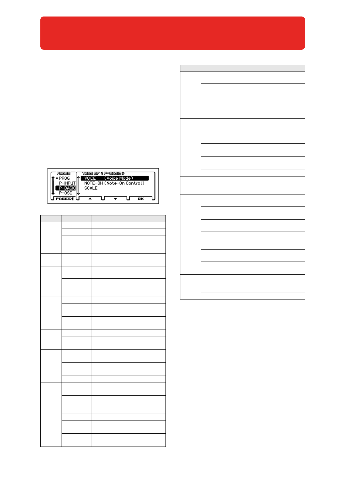
Here's how you can select each page.
• Use the PAGE+/- buttons.
• Press the MENU button to access the page menu, use the
PAGE+/- buttons to select a page, and press the MENU (OK)
button or the ENTER button.
• While the above page menu is displayed, press the FUNCTION
(TABS) button, then use the PAGE+/- buttons to select a page
by its tab, and then press the MENU (OK) button or the ENTER
button.
• Hold down the MENU button and press the PAGE- or PAGE+
buttons.
For details, see “Selecting pages and tabs” on page 11 of the
Operation Guide.
Page Tabs Main content
MAIN Select and play programs (see page 2)
TONE Easy sound editing (see page 3)
PROG
P–INPUT/
CTRL
P–BASIC
P–OSC
P–PITCH
P–PITCH EG
P–FILTER
P–FILTER EG
P–AMP
P–AMP E G
MIXER
ARP Simple arpeggiator editing (see page 4)
AUDIO IN External audio input settings (see page 5)
CONTROLLERS SW1 and 2 function assignments (see page 6)
VOICE
NOTE-ON
SCALE Scale settings (see page 10)
MS1...MS4 Multisample and drum kit settings (see page 11)
VEL Oscillator velocity zone settings (see page 13)
BASIC Oscillator 1 and 2 pitch settings (see page 14)
MOD Pitch modulation settings (see page 15)
PORTA Portamento settings (see page 17)
ENVELOPE Pitch EG settings (see page 18)
L-MOD Pitch EG level modulation settings (see page 19)
T-MOD Pitch EG time modulation settings (see page 20)
BASIC Oscillator 1 and 2 filter settings (see page 21)
MOD Filter modulation settings (see page 23)
EG-I Filter EG intensity settings (see page 24)
LFO-I Filter LFO intensity settings (see page 25)
KTRK Filter keyboard tracking settings (see page 26)
ENVELOPE Oscillator 1 and 2 filter EG settings (see page 28)
L-MOD Filter EG level modulation settings (see page 29)
T-MOD Filter EG time modulation settings (see page 30)
BASIC
MOD Amp modulation settings (see page 33)
KEYTRK Amp keyboard tracking settings (see page 34)
ENVELOPE Oscillator 1 and 2 amp EG settings (see page 36)
L-MOD Amp EG level modulation settings (see page 37)
T-MOD Amp EG time modulation settings (see page 38)
OSC1, 2, Drum Track, and step sequencer volume
adjustment and mute settings (see page 4)
Basic program settings, such as Oscillator mode
(see page 7)
Key zone, and timing setting s following note-on
(see page 8)
Oscillator 1 and 2 amp (volume) and pan settings
(see page 32)
Page Tabs Main content
1. WAV
1. FRQ
P–OSC LFO
2. WAV
2. FRQ
LFO.W Common LFO waveform settings (see page 42)
P–CMN LFO/
KT
P–AMS
MIXER
P–ARP
P–DRUM
TRACK
P–STEP SEQ
P–FX
ROUTING
P–IFX IFX1, 2, 3, 4, 5 Insert effect 1–5 settings (see page 61)
P–MFX
LFO.F
KT.1 Common keyboard tracking 1 settings (see page 44)
KT.2 Common keyboard tracking 2 settings (see page 45)
1 Oscillator 1 and 2 AMS mixer 1 settings (see page 45)
2 Oscillator 1 and 2 AMS mixer 2 settings (see page 50)
SETUP Arpeggiator settings (see page 50)
SCAN ZONE Arpeggiator trigger region settings (see page 50)
PATTERN
PROGRAM Drum Track program selection (see page 50)
BASIC
EDIT Step on/off entry (see page 56)
INST Instrument settings (see page 57)
MOD
MIX Drum program selection (see page 58)
BUS
SEND
IFX
MIXER Post-insert effect routing settings (see page 61)
SETUP
MFX1, 2 Master effect 1 and 2 settings (see page 62)
Oscillator 1 and 2 LFO1 waveform settings
(see page 39)
LFO1 frequency and modulation settings
(see page 41)
Oscillator 1 and 2 LFO2 waveform settings
(see page 42)
LFO2 frequency and modulation settings
(see page 42)
Common LFO frequency and modulation settings
(see page 43)
Drum Track pattern selection and trigger region
settings (see page 50)
Step sequencer program selection and length settings
(see page 55)
Step sequencer effects such as accent and swing
(see page 57)
Oscillator 1 and 2 insert effect bus settings
(see page 59)
Oscillator 1 and 2 master effect send level settings
(see page 59)
Insert effect type selection and chain setti ngs (see page 60)
Master effect type selection and chain settings
(see page 62)
1
Page 10
Program mode
0: PROG (Program)
This is the main Program mode page. Here you can:
In the PROG page, MIDI data is transmitted and received on
the global MIDI channel that's specified by MIDI Channel
(G–MIDI> BASIC). However, MIDI data for the Drum Track
and the step sequencer is transmitted and received on the
Drum Track Prog MIDI Ch and the Step Seq Prog MIDI Ch
(G–MIDI> OUT) respectively.
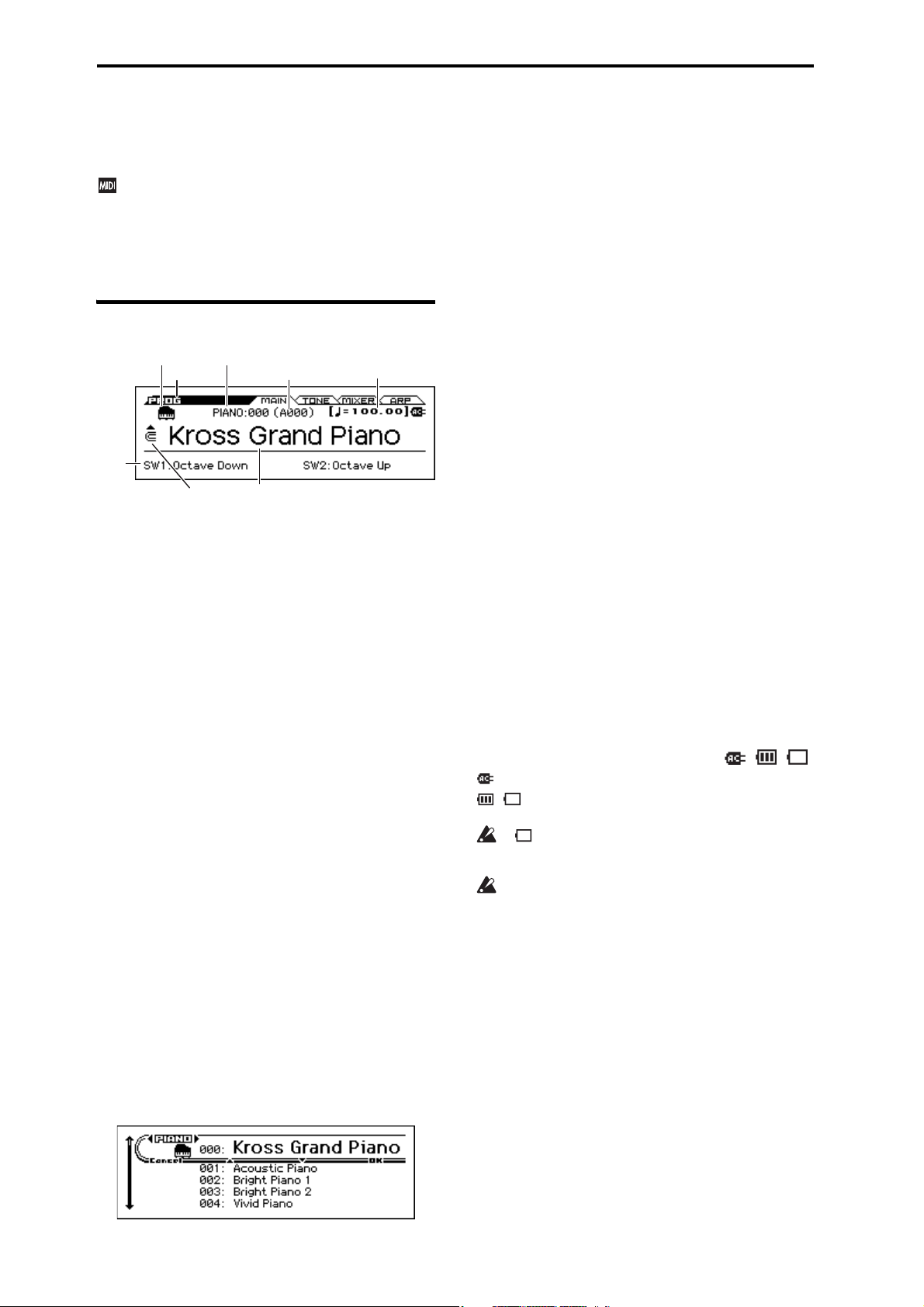
0–1: MAIN
Category: Index No. Category Icon
Mode (Bank No.)
SW
Info.
Category Select Icon
Program Select
Category Icon [USE/GM, PIANO...DRUM/SFX]
This shows the program's category icon. For the USER category
and the GM bank, the icon is shown at the left of the PIANO–
DRUM/SFX icon.
Category [PIANO...USER]
This is the program category name.
All programs are organized into 11 preset categories and 1 user
category.
PIANO, E.PIANO, ORGAN, BELL, STRINGS, BRASS, SYNTH
LEAD, SYNTH PAD, GUITAR, BASS, DRUM/SFX, USER
Index No. (Bank No.)
[000... (A…D, U: 0...127, G, g1...g9, gd: 1...128)]
The index number sorts the programs of the A–D, U, and GM
banks, starting from number 000.
The index number is the number that is used to transmit or receive
MIDI program changes; it ranges from 0–127 for banks A–D and
U, and from 1–128 for the GM banks. Of the GM banks g1–g9,
programs that have no variation sound are indicated by *, and GM
basic sounds will be recalled for these.
Note: Each bank has limitations on saving. (see page 63)
Category Select Icon
Where this icon appears, you can use the sound selector
(CATEGORY dial, SELECT dial) to select a program.
Program Select
This is the name of the selected program.
Sound select list
This lists the programs in each category. Select a program and play
it. Here's how to access this list and play a program.
1. In the PROG> MAIN page, the list will appear when you
turn the CATEGORY dial or SELECT dial, or press the
ENTER button.
Tempo
2. If you want to switch to a different category, use the CATE-
GORY dial or the cursor buttons .
3. To select sounds, use the SELECT dial, the value dial, or
the cursor buttons .
4. If you return to the PROG> MAIN page by pressing the
OK (MENU) button, the sound you selected in step 3 will be
selected. If you press the Cancel (FUNCTION) button, your
selection will be cancelled, and the sound that had been
selected before you opened the list will be selected.
Note: To change the category assignment of each program, use the
Write Program dialog box.
To s witc h prog rams
• Turn the value dial, or use the cursor buttons .
• Use the sound selector list (see “Sound select list”)
• You can use a foot switch to select programs.
(See “Foot Switch Assign” on page 164 and “Foot Switch
Assign List” on page 291)
• You can select programs by transmitting a MIDI Program
Change from a connected external MIDI device.
Note: MIDI program changes are transmitted using the Bank No.
shown in the screen.
(Tempo) [40.00... 300.00, EXT]
This is the tempo for the current Program, which applies to the
arpeggiator, drum track, step sequencer, tempo-synced LFOs, and
tempo-synced effects.
040.00...300.00: Indicates the tempo
In this page, you can adjust the tempo by turning the TEMPO knob
or by pressing the TAP button at the desired interval. In the P–
INPUT/CTRL> Controllers page you can enter a numeric value.
EXT is displayed if the MIDI Clock (G–MIDI> BASIC) is set to
External MIDI or External USB. This is also shown if the MIDI
Clock setting is Auto and MIDI clock data is being received from
an external device. If the tempo source is EXT, the arpeggiator etc.
will synchronize to MIDI clock data from an external MIDI
device.
Battery/AC Icon [ , , ]
: Indicates that the AC adapter is being used.
, : Indicates that batteries are being used. The approximate
amount remaining is shown.
If is flashing, the batteries are almost exhausted.
Immediately save any important data, and either install fresh
batteries or switch to using the AC adapter.
If the batteries are exhausted, remove them immediately.
Leaving exhausted batteries installed may cause
malfunctions such as battery leakage. You should also
remove the batteries if you won’t be using the unit for an
extended period of time.
SW Info.
SW1, SW2: Indicates the functions that are assigned to the SW1
and SW2 buttons.
2
Page 11

0–2: TONE (Play Tone Adjust)
The Tone Adjust function lets you make simple changes to the
sound by adjusting the program's main parameters, such as the
filter or the filter and amp EG.
Tip: In Combination and Sequencer modes, Tone Adjust also lets
you edit Program parameters without the need to save a different
version of the original Program. For more information on Tone
Adjust in these modes, please see page 75 and 114.
Using and saving the Tone Adjust settings
Your editing will affect the sound immediately, but the values of
the original program parameters will not change until you save the
program. When you save the program, the result of your Tone
Adjust settings will be saved in the program parameters. At that
point, all of the Tone Adjust parameter values will be reset to 0.
How parameters and MIDI control changes (CC) affect each other
Most parameters will also affect the parameters that are controlled
via MIDI control changes.
Tone Adjust and control changes work independently. For
example, you can use the Tone Adjust function to reduce the value
of a parameter, and then use a control change to increase it.
The MIDI control change numbers (CC#) corresponding to each
Tone Adjust parameter are shown below.
Cutoff: CC#74
Resonance: CC#71
EG Intensity: CC#79
Vel. Intensity: Not supported
Attack: CC#75
Decay: CC#75
Sustain: CC#70
Release: CC#72
See page 297, 303
0: PROG (Program) 0–2: TONE (Play Tone Adjust)
Vel. Intensity (Amp Velocity Intensity) [–99...+99]
This scales the effect of velocity on the Amp level.
–99 removes the velocity modulation entirely. +99 means
maximum modulation in the same direction, positive or negative,
as the original Program.
EG
Attack (Filter/Amp EG Attack Time) [–99...+99]
This adjusts the attack time and other related parameters of all
filter EGs and amp EGs in a single action.
When the value is +1 or more, this also affects the Amp EG’s Start
and Attack Levels, Start Level AMS, and Attack Time AMS, as
described below:
Between values of +1 and +25, the Start Level, Start Level AMS,
and Attack Time AMS will change from their programmed values
to 0. Over the same range, the Attack Level will change from its
programmed value to 99.
Decay (Filter/Amp EG Decay Time) [–99...+99]
This scales the decay and slope times of the Filter and Amp EGs. It
interacts with CC# 75.
Sustain (Filter/Amp EG Sustain Level) [–99...+99]
This scales the sustain levels of the Filter and Amp EGs.
Release (Filter/Amp EG Release Time) [–99...+99]
This scales the release times of the Filter and Amp EGs.
The compare function is not available for any editing that
uses the Tone Adjust parameters.
Category: Index No. , Category Select Icon, Program Select
Select the program.
TONE ADJUST
Cutoff (Filter Cut Off) [–99...+99]
This scales the cutoff frequency of all of the filters at once. It
affects both Filters A and B.
Resonance (Filter Resonance) [–99...+99, CC#71]
This scales the resonance of all of the filters at once. It affects both
Filters A and B.
EG Intensity (Filter EG Intensity) [–99...+99, CC#79]
This scales the effect of the Filter EG on the cutoff frequency. It
affects Filters A and B simultaneously.
If this is set to -99, the filter EG will have no effect. +99 means
maximum. Modulation is in the same direction, positive or
negative, as the original Program. For instance, if the original
Program’s EG Intensity was set to –25, then setting the Tone
Adjust to +99 moves the EG Intensity to –99.
3
Page 12

Program mode
Pattern
0–3: MIXER (Play Mixer)
Here is where you can adjust the volume of oscillators 1 and 2, the
Drum Track and the step sequencer, and mute or solo them. Use
the Solo Setting function to turn solo on/off. (see page 63)
Tip: You can use the Hold Balance function to adjust these four
volume settings simultaneously. This function is a convenient way
to make adjustments while preserving the volume balance.
Category: Index No. , Program Select
Select the program.
OSC1
Play/Mute [Play, Mute]
Play: Oscillator 1 will sound.
Mute: Oscillator 1 will be muted (silent).
Vol (Volume) [000...127]
Adjusts the volume of Oscillator 1.
OSC2
Play/Mute [Play, Mute]
Play: Oscillator 2 will sound.
Mute: Oscillator 2 will be muted (silent).
Note: OSC2 Play/Mute cannot be set for a program whose
Oscillator Mode is Single or Drums.
Vol (Volume) [000...127]
Adjusts the volume of Oscillator 2.
DRUM TRACK
Play/Mute 1 [Play, Mute]
Play: The drum track will sound.
Mute: The drum track will be muted (silent).
Vol (Volume) [000...127]
Adjusts the volume of the drum track.
STEP SEQ
Play/Mute [Play, Mute]
Play: Step sequencer will sound.
Mute: Step sequencer will be muted (silent).
Vol (Volume) [000...127]
Adjusts the volume of step sequencer.
0–4: ARP (Arpeggiator)
This is the easy edit page for the arpeggiator. For more detailed
editing, use the P–ARP page.
Category: Index No. , Program Select
Select the program.
MOD (Modulation)
[GATE] [–64...+00...+63]
Specifies the length (gate time) of each note in the arpeggio(see
page 51).
[VEL} (VELOCITY) [–64...+00...+63]
Specifies the velocity of the notes in the arpeggio (see page 51).
{SWING} [–64...+00...+63]
This parameter shifts the timing of the odd-numbered notes of the
arpeggio (see page 52).
When each MOD parameter is at +00, the effect will be as
specified by the Gate, Velocity, and Swing parameters of the PARP> SETUP page.
Pattern [Preset: UP...RANDOM, 0000…1027]
Octave [1oct, 2oct, 3oct, 4oct]
Resolution [
Sort [Off, On]
Latch [Off, On]
Key Sync. [Off, On]
Keyboard [Off, On]
Note: These parameters can also be set from P13: P–ARP (see
page 51).
V
0–1...4: FUNCTION
•0: Write Program, Write/Initialize Program see page 63
•1: Solo Setting see page 63
•2: Compare see page 64
•3: Auto Song Setup see page 64
•4: Add to Favorite see page 64
•5: Hold Balance see page 64 (only MIXER page)
•6: Copy Arpeggiator see page 65 (only ARP page)
For more information, please see the “Program: Function” section
on page 63.
, , , , , , , ]
4
Page 13
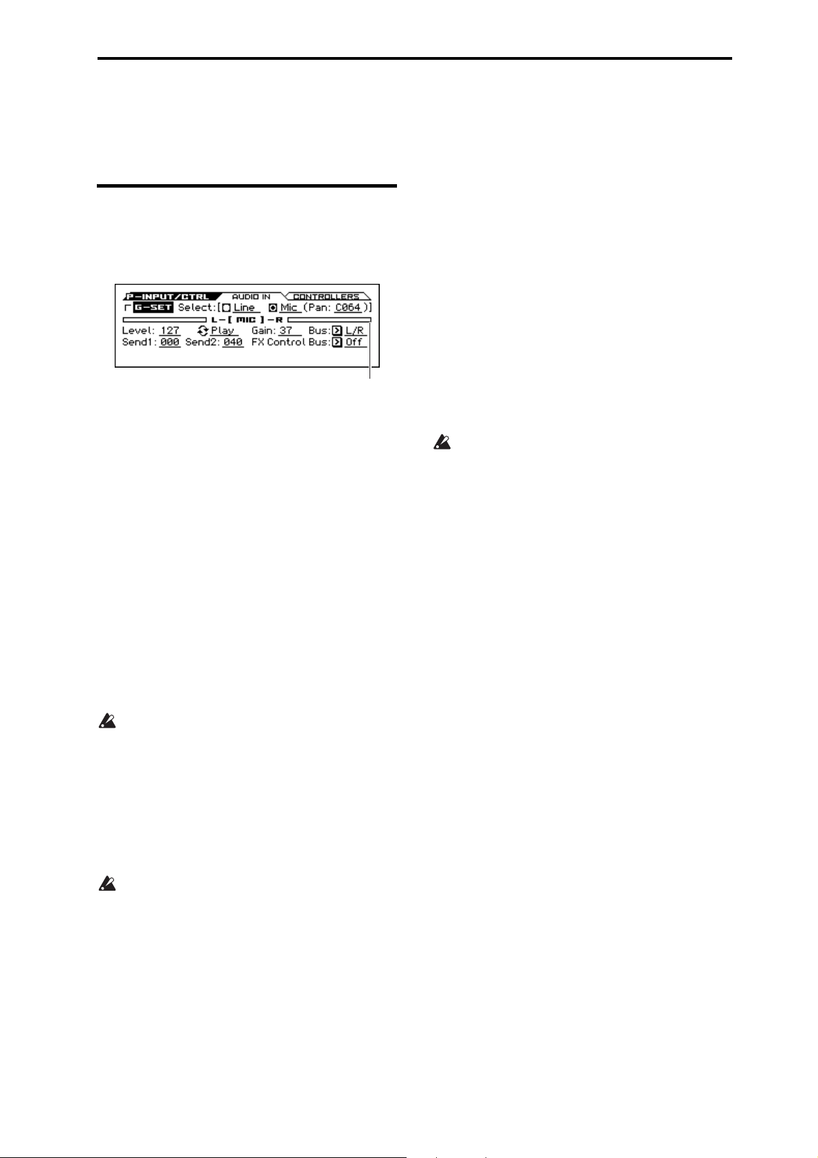
1: P–INPUT/CTRLS (Input/Controllers 1–1: AUDIO IN
Input Level Meter
1: P–INPUT/CTRLS (Input/Controllers
1–1: AUDIO IN
About the AUDIO IN button
Settings found in this page are active when the front panel AUDIO
IN button is on, allowing an external audio signal to be input.
G-SET (Use Global Setting) [Off, On]
On (checked): The general settings in the GLOBAL mode G–
INPUT/CTRL page will be used as the external audio input
settings. If you want to use the same external input for multiple
programs, it is convenient to turn this On (checked) for each
program, and make adjustments in GLOBAL mode.
Off (unchecked): The Line or Mic settings you make in this page
will be used.
Since this allows you to save external audio input settings that are
appropriate for a specific program, it is convenient to use this
setting in conjunction with the appropriate audio input settings, for
example when you're saving a program as a vocoder effect
program. (“Example: Vocoder (Program)” on page 199)
Select [Line, Mic]
Selects the external input jack that will be used.
Line: LINE IN jack (line level, stereo)
Mic: MIC IN jack (mic level, monaural)
You can adjust the following parameters individually for LINE
and MIC.
You can't use the Line input and Mic input simultaneously.
Pan [L000...L063, C064, R065...R127]
If the Select parameter is set to Mic, this lets you adjust the pan
settings of the external audio signal that's being input from the
MIC IN jack. C064 pans the sound to the center.
You can't specify this for the Line input. Its stereo panning is fixed.
Input Level Meter
Indicates the level of the external audio that's being input to the
KROSS.
If the input is overloaded, the [LINE] or [MIC] indicators in
the middle of the level meter will be highlighted. Adjust the
Gain of the input stage or the Level parameter that follows
the AD converter.
Solving distortion caused by input overload
If the audio input is too loud, the sound may be distorted.
If the [LINE] or [mic] indication in the Input Level Meter is
highlighted, distortion is occurring in the input stage. Adjust the
Gain parameter or the volume of your connected device so that this
indication is not highlighted.
If there is distortion even though this indication is not highlighted,
it may be that an effect of the KROSS is causing the distortion.
Adjust the Level parameter to lower the signal level, or adjust the
effect settings (such as the Input Trim parameter).
Mute/Play [Mute, Play]
This specifies whether the external audio input signal will be
silenced (muted) or audible.
Mute: The audio input will be silenced (muted).
Play: The audio input will be heard.
Note: Even if this is set to Play, the audio input will not be heard if
the AUDIO IN button is off (unlit).
Gain [00...82, MAX]
This adjusts the level of the external audio input signal at the input
stage. See “Solving distortion caused by input overload.”
The input gain setting (Gain) is shared by the global setting
(G-SET on) and the individual setting (G-SET off). To save
the setting, select the setting in Global mode and then use the
Write Global Setting function to save it. Although you can
edit this in the AUDIO IN page or the QUICK SETTING
dialog box of each mode, you can't save it as an individual
setting (G-SET off) for a program, combination, or song.
Bus (Bus Select) [L/R, IFX1...5, Off]
Specifies the output bus for the external audio signal.
L/R: The external audio input signal is output to the L/R bus.
IFX1...5: The external audio input signal is output to the IFX1–5
bus. Use this setting if you want to apply insert effects to the input
signal.
Off: The external audio signal is not output to any bus.
Send1 [000...127]
Send2 [000...127]
Specify the send levels where the external audio input signal is
sent to the master effects. Use these when you want to apply
chorus or delay/reverb to the Mic input sound.
Send1 sends the signal to master effect 1.
Send2 sends the signal to master effect 2.
If Bus (Bus Select) is set to IFX1–5, the send levels to the master
effects are set by the Send1 and Send2 parameters (see page 58)
after the signal passes through IFX1–5. (see page 61)
FX Control Bus [Off, FC1, FC2]
This outputs the external audio input signal to the FX Control bus
(stereo two-channel FX Ctrl1, 2). (see page 199)
Level [000...127]
This specifies the level of the external audio signal that's being
input. Normally you'll leave this at 127.
The analog audio signal from the LINE IN or MIC IN jack is
converted into a digital signal by the AD converter. This Level
parameter adjusts the amount of signal immediately after it is
converted into digital; if the audio input is distorted, see “Solving
distortion caused by input overload.”
5
Page 14
Program mode
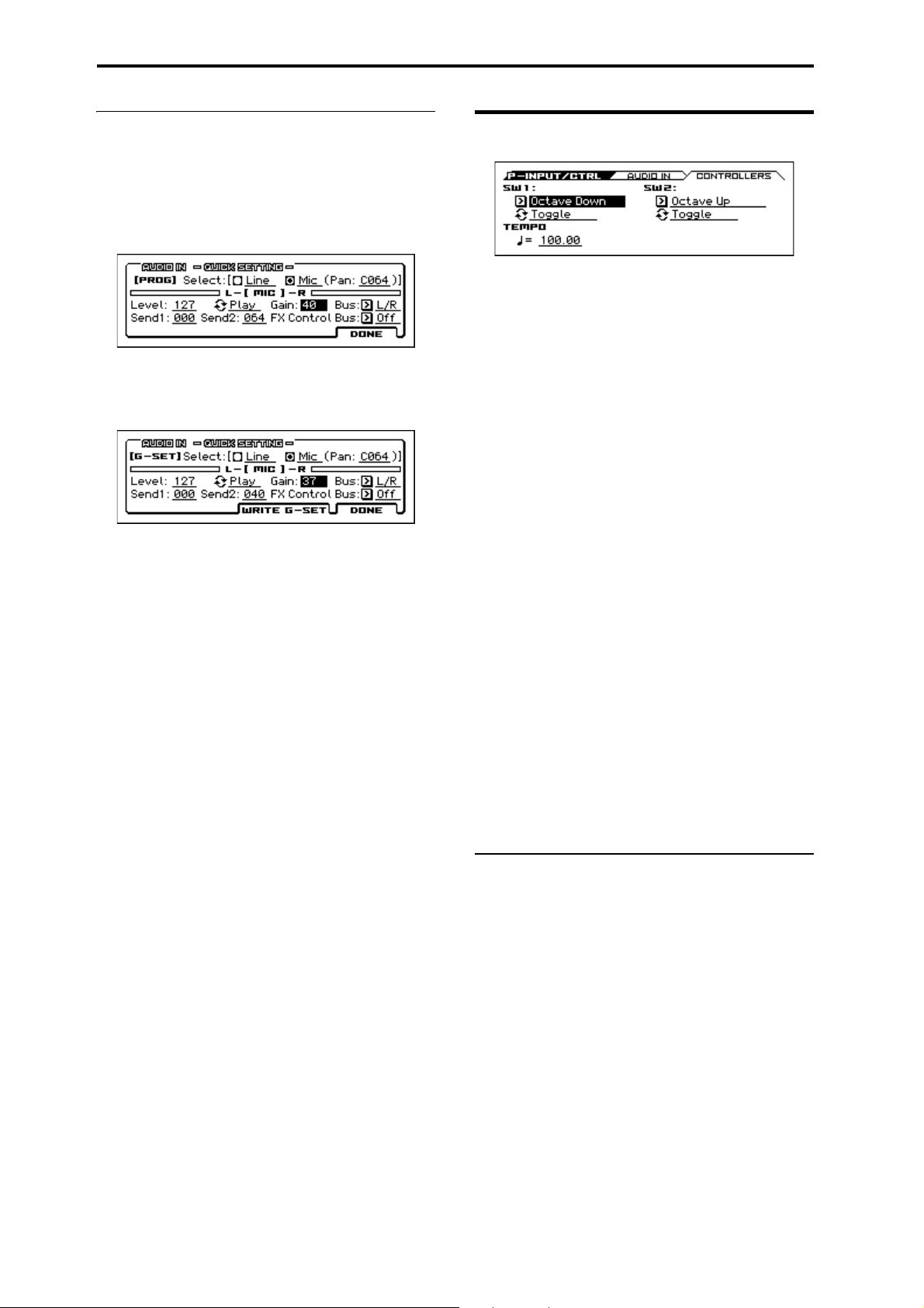
AUDIO IN – QUICK SETTING
If you hold down the EXIT button and press the AUDIO IN
button, the current audio in setting will appear. This is referred to
as the audio in quick setting. When a different page is open, this
provides a convenient way to quickly access the settings without
having to open the AUDIO IN page.
The following illustration shows the case when G-SET is Off.
If G-SET is ON, the GLOBAL setting AUDIO IN is shown and
can be edited. When you press the WRITE G-SET (PAGE+)
button, the WRITE GLOBAL SETTING dialog box will appear,
allowing you to save the setting.
1–2: CONTROLLERS (Controllers Setup)
Here you can specify the functions of the front panel SW1 and
SW2 buttons, and set the tempo.
SW1
Assign [Off, ..., Pitch Bend Lock]
Selects the function that's used by SW1. This assigns the function
of SW1 (see “SW1, SW2 Assign List” on page 290).
Note: If you change the function setting, the status is reset to off.
Note: The on/off status of the SW1, SW2 switches is memorized
when you save the program.
Mode [Toggle, Momentary]
This specifies the on/off function when you press the SW1 switch.
Toggle: The state will alternate between On and Off each time you
press the SW1 switch.
Momentary: The state will remain On only while you continue
holding down the SW1 switch.
SW2
Assign [Off, ..., Pitch Bend Lock]
Mode (SW2 Mode) [Toggle, Momentary]
This assigns the function of SW2. The functions that can be
assigned to SW2 are the same as for SW1, with the substitution of
SW2 Mod. (CC#81) instead of the SW1’s SW1 Mod. (CC#80).
TEMPO
(Tempo) [40.00... 300.00, EXT]
This is the tempo for the current Program, which applies to the
arpeggiator, drum track, step sequencer, tempo-synced LFOs, and
tempo-synced effects (see “ (Tempo)” on page 2).
V
1–1, 2: FUNCTION
•0: Write Program, Write/Initialize Program see page 63
•1: Solo Setting see page 63
•2: Compare see page 64
•3: Auto Song Setup see page 64
•4: Add to Favorite see page 64
For more information, please see the “Program: Function” section
on page 63.
6
Page 15
2: P–BASIC 2–1: VOICE (Voice Mode)
Input Level Meter
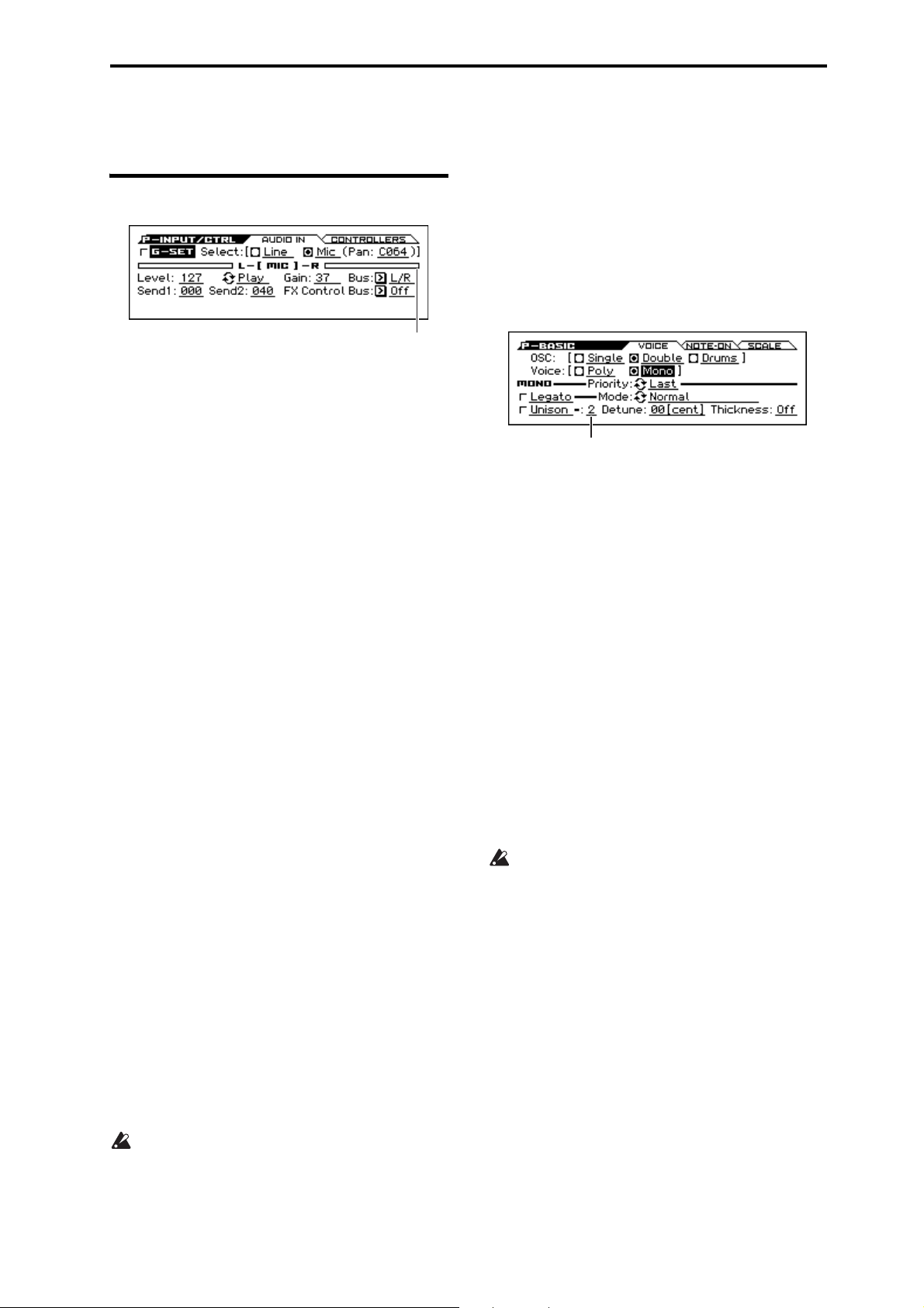
2: P–BASIC
2–1: VOICE (Voice Mode)
This page contains all of the basic settings for the Program.
Among other things, you can:
• Set up the Program to be a Single, a Double, or a Drum Kit.
• Set the Program to play polyphonically or monophonically.
OSC (Oscillator Mode) [Single, Double, Drums]
Specifies the Program’s oscillator assignment; whether it will use
one or two oscillators, or a drum kit.
Single: The program will use one oscillator (Oscillator 1, Filter 1,
Amplifier 1). In this case, the program will normally have a
maximum of 80-note polyphony.
Double: The program will use two oscillators (Oscillator 1/2,
Filter 1/2, Amplifier 1/2). In this case the program will normally
have a maximum of 40-note polyphony.
Drums: The program will use one oscillator (as when Single is
selected), but Oscillator 1 will be assigned a drum kit instead of a
multisample. In this case the program will normally have a
maximum of 80-note polyphony.
Voice Assign Mode [Poly, Mono]
Select the basic voice allocation mode. Depending on which one
you select, various other options will appear, such as Poly Legato
(Poly mode only) and Unison (Mono mode only).
Poly: The program will play polyphonically, allowing you play
chords.
Mono: The program will play monophonically, producing only
one note at a time.
Poly
These parameters are available when the Voice Assign Mode is set
to Poly.
Legato (Poly Legato) [Off, On]
Legato means to play notes in a smooth and connected manner; the
next note is played before the last note is released. This is the
opposite of playing detached.
On (checked): When you play a legato phrase, only the first note
of that phrase (and within approximately the first 30 msec) will
use the normal multisample start point specified by Start Offset
(P–OSC); all subsequent notes will use the legato start point
specified for each multisample.
Note: This is a useful way to simulate the percussive attack of a
tonewheel-type organ.
Off (unchecked): Notes will always use the setting of the Sta rt
Offset, regardless of whether you play legato or detached.
With some Multisamples, Poly Legato may not have any
effect.
Single Trigger [Off, On]
Single Trigger is available when the Voice Assign Mode is set to
Poly.
On (checked): When you play the same note repeatedly, the
previous note will be silenced before the next note is sounded, so
that the two do not overlap.
Off (unchecked): When you play the same note repeatedly, the
notes will overlap.
MONO
These parameters are available when the Voice Assign Mode is set
to Mono.
Number of Voices
Legato (Mono Legato) [Off, On]
Legato means to play notes in a smooth and connected manner; the
next note is played before the last note is released. This is the
opposite of playing detached.
When Mono Legato is On, the first note in a legato phrase will
sound normally, and then subsequent notes will have a smoother
sound, for more gentle transitions between the notes.
The Mode parameter, below, switches between two different
Mono Legato effects, each of which achieves this smoothness in a
different way. See the description of that parameter for more
details.
On (checked): When you play with legato phrasing, the notes
within a legato phrase will sound smoother, according to the
setting of the Mode parameter, below.
Off (unchecked): Legato phrasing will produce the same sound as
detached playing.
Mode [Normal, Use Legato Offset]
Normal: When you play legato, the multisample, envelopes, and
LFOs will not be reset; only the pitch of the oscillator will change.
This setting is particularly effective for wind instruments and
analog synth sounds.
With this option, the pitch may occasionally be incorrect,
depending on which multisample you play, and where on the
keyboard you play.
Use Legato Offset: When you play legato, the second and
subsequent notes will use the legato start point specified for each
multisample, rather than the Start Offset (P–OSC) setting.
This is effective when used with a multisample where you’ve
assigned a specific legato offset point. For example, you might use
it to control the attack of a breathy, slow-attack sax sound. On
some multisamples, this will have no effect.
Envelopes and LFOs will still be reset, as they are with detached
playing.
Priority [Low, High, Last]
This parameter determines what happens when more than one note
is being held down.
Low: The lowest note will sound. Many vintage, monophonic
analog synths work this way
High: The highest note will sound.
Last: The most recently played note will sound.
7
Page 16
Program mode
Unison [On, Off]
On (checked): When Unison is on, the Program uses two or more
stacked, detuned voices to create a thick sound.
Use the Number of Voices and Detune parameters to set the
number of voices and amount of detuning, and the Thickness
parameter to control the character of the detuning.
Off (unchecked): The Program plays normally.
Number of Voices [2...6]
Number of Voices is available when Unison is On.
This controls the number of detuned voices that will be played for
each note when using Unison. It applies only when Unison is On.
Detune [00...99 cents]
Detune is available when Unison is On.
This parameter sets the tuning spread for the Unison voices, in
cents (1/100 of a semitone). The Thickness parameter, below,
controls how the voices are distributed across the detune amount.
When Thickness is Off, the voices are distributed evenly, centered
around the basic pitch.
For instance, let’s say that the Number of voices parameter is set
to 3, Detune is set to 24, and Thickness is Off:
Voice one will be detuned down by 12 cents, voice two will not be
detuned, and voice three will be detuned up by 12 cents.
Voic e Detune
1
2
3+12
As another example, let’s say that Detune is still set to 24 and
Thickness is still Off, but the Number of voices is set to 4:
Voice one will still be detuned down by 12 cents, voice two will be
detuned down by 4 cents, voice three will be detuned up by 4
cents, and voice 4 will be detuned up by 12 cents.
Voic e Detune
1
2
3+4
4+12
–12
0
–12
–4
Thickness [Off, 01...09]
Thickness is available when Unison is On.
This parameter controls the character of the detuning for the
unison voices.
Off: Unison voices will be evenly distributed across the Detune
range, as shown above.
01–09: Unison voices will be detuned in an asymmetric way,
increasing the complexity of the detune amount, and changing the
way that the different pitches beat against one another. This creates
an effect similar to vintage analog synthesizers, where oscillators
would frequently drift slightly out of tune. Higher numbers
increase the effect.
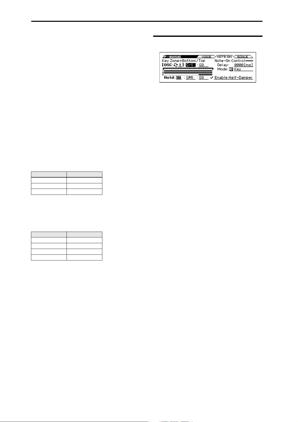
2–2: Note-On (Note-On Control)
Here you can adjust the following settings.
• Make keyboard split settings for OSC1, OSC2, and Hold.
• Enable/disable the half-damper function.
• Specify the timing of the notes played from the keyboard.
OSC (Oscillator Select) [1, 2]
Select the oscillator (1 or 2) that you want to edit.
Note: Oscillator 2 can be selected if Oscillator Mode is set to
Double.
To edit parameters such as the pitch, filter, or amp of oscillator 1 or
oscillator 2, use the cursor buttons to select [OSC: 1/2], and use
the ENTER button or the VALUE dial to select the oscillator that
you want to edit.
Key Zone – Bottom/Top
You can create keyboard splits by setting top and bottom key
limits for Oscillators 1 and 2. Also, you can control the keyboard
range where the Hold parameter takes effect.
Note values and velocity values can also be entered using the
keyboard. (see page 12 of the Operation Guide)
Key Zone Bottom [C–1...G9]
This sets the lowest key where the Oscillator will play.
Key Zone Top [C–1...G9]
This sets the highest key where the Oscillator will play.
Zone Graphic
Note-On Control
Delay [0000ms...5000ms, KeyOff]
This specifies the amount of time from when you press a key until
the oscillator actually begins to sound.
This is most useful in Double Programs, for delaying one
oscillator in relation to the other.
KeyOff is a special setting. Instead of delaying the sound by a
particular amount of time, the sound will play as soon as you
release the key.
You can use this to produce the “click” sound that is heard each
time you release a key of a harpsichord.
In general, when you use the KeyOff setting, it’s also best to set
the oscillator’s Amp EG Sustain Level to 0.
Mode [Key, Key + Damper]
Normally, you play notes simply by pressing keys on the
keyboard. In special cases, however, you can set this parameter so
that you must first be holding down the damper pedal, and then
press a key, in order to play a note. For instance, this can be useful
when modeling the behavior of a piano soundboard.
Key is the normal mode.
When you select Key + Damper, notes will only sound if the
damper pedal is being held down. When the damper pedal is
released, all notes will be stopped even if they are still being held
down.
8
Page 17

2: P–BASIC 2–2: Note-On (Note-On Control)
Hold
Hold [On, Off ]
Hold is like permanently pressing down on the sustain pedal. In
other words, notes continue to sound as if you were holding down
the key - even after you lift your fingers from the keyboard.
Unless the Sustain Level is set to 0 in Amp EG 1 (and Amp EG 2
in a Double Program), the sound will play for the entire length of
the multisample(s).
On (checked): The Hold function is enabled for the range set by
the Hold Bottom and Hold Top parameters, below.
Off (unchecked): Notes will play normally. This is the default
setting.
Using Hold with Drum Kits
Hold can be especially useful for drum programs, since it lets the
drum samples ring out naturally. In general, when you set the
Oscillator Mode to Drums, it’s good to set Hold to On.
Once you’ve turned on Hold for a drum program, the function is
controlled on a note-by-note basis according to settings within the
selected Drum Kit.
If a key’s Enable Note Off Receive parameter (see page 172) is
unchecked, the note will be held.
If the key’s Enable Note Off Receive parameter is checked, it will
not be held.
If you turn off Hold in the Program, no keys will be held regardless of their Enable Note Off Receive setting.
Half-Damper Pedal and Release Time
The amount of modulation depends on whether the Amp EG
Sustain Level is set to 0 (as is the case with most acoustic piano
sounds), or set to 1 or more. The modulation is continuous, from
1x (no change) to 55 times longer; the table below shows a
selection of representative points.
Half-Damper modulation of Amp EG Release Time
CC#64 Value
01x 1x
32 2.1x 2.1x
64 3.2x
80 5.9x
96 22.3x
127 55x
Multiply Amp EG Release Time by…
If Sustain = 0 If Sustain = 1 or more
3.2x
Using Hold with Acoustic Pianos
Hold is also useful for simulating the top octaves of an acoustic
piano, in where notes always sustain until they fade out naturally,
regardless of how long you hold the key.
The Hold Bottom and Hold Top parameters are designed for
exactly this purpose. They let you limit the effect of the Hold
parameter to a specific range of the keyboard.
Hold Bottom [C–1...G9]
This sets the lowest key affected by the Hold function.
Hold Top [C–1...G9]
This sets the highest key affected by the Hold function.
Enable Half-Damper [On, Off ]
When this is On (checked), Half-Damper pedals, normal sustain
pedals, and MIDI CC# 64 will all modulate the Amp EG, as
described below.
When this is Off (un-checked), the pedals and MIDI CC#64 will
still hold notes as usual, but will not modulate the Amp EG.
A half-damper pedal is a special type of continuous foot pedal,
such as the Korg DS-1H. In comparison to a standard footswitch,
half-damper pedals offer more subtle control of sustain, which can
be especially useful for piano sounds.
The KROSS will automatically sense when a half-damper is
connected to the rear-panel DAMPER input. For proper operation,
you will also need to calibrate the pedal, using the Half Damper
Calibration function in the Global menu.
The off and full-on positions of the half-damper work just like a
standard footswitch. In conjunction with the Enable Half-
Damper parameter, below, intermediate positions allow a
graduated control of sustain, similar to the damper pedal of an
acoustic piano.
9
Page 18

Program mode
2–3: SCALE
Selects the basic scale for the Program.
Scale Type [
Selects the basic scale.
Note that for many of the scales, the setting of the Key parameter,
below, is very important.
Equal Temperament: This is the most widely used scale by far, in
which each semitone step is spaced at equal pitch intervals.
Equal Temperament allows easy modulation, so that a chord
progression played in the key of C sounds roughly the same as the
same progression played in F#. Sacrificed, however, is some of the
purity of individual intervals offered by the scales below.
Pure Major: In this temperament, major chords of the selected
key will be perfectly in tune.
Pure Minor: In this temperament, minor chords of the selected
key will be perfectly in tune.
Arabic: This scale includes the quarter-tone intervals used in
Arabic music.
Pythagoras: This scale is based on ancient Greek music theory,
and is especially effective for playing melodies. It produces
completely pure fifths, with one exception, at the expense of
detuning other intervals– thirds in particular.
As much as Pythagoras might have liked to do so, it’s not possible
to make all the fifths pure while also keeping the octave in tune.
For the sake of the octave, one of the fifths, the interval from the
sharp fourth degree to the sharp first degree is made quite flat.
Werkm eiste r (Werkmeister III): This scale was one of the many
temperament systems developed towards the end of the Baroque
period. These “Well-Tempered” tunings were aimed at allowing
relatively free transposition although you’ll still notice that the
different keys maintain their own distinct characteristics, unlike
Equal Temperament.
J.S. Bach was referring to these new scales in his title, “The WellTempered Clavier.” As such, this group are particularly
appropriate for late baroque organ and harpsichord music.
Kirnberger (Kirnberger III): This is a second “Well-Tempered”
tuning, dating from the early 18th century.
Slendro: This is an Indonesian gamelan scale, with five notes per
octave.
When Key is set to C, use the C, D, F, G and A notes. Other keys
will play the normal equal-tempered pitches.
Pelog: This is another Indonesian gamelan scale, with seven notes
per octave.
When Key is set to C, use the white keys. The black keys will play
the equal tempered pitches.
Stretch: This tuning is used for acoustic pianos.
User All Notes Scale: This is a user-programmed scale with
different settings for all 128 MIDI notes. You can set up this scale
in Global mode (G–USER SCALE> ALL).
User Octave Scale 00–15: These are user-programmed scales
with settings for each of the 12 notes in an octave. You can set
them up in Global mode (G–USER SCALE> OCTAVE).
Equal Temperament…User Octave 15
Key (Scale Key) [C…B]
Selects the key of the specified scale.
This setting does not apply to the Equal Temperament, Stret ch,
and User All Notes scales.
If you’re using a scale other than Equal Temperament, the
combination of the selected scale and the Key setting may
skew the tuning of the note. For example, A above middle C
might become 442 Hz, instead of the normal 440 Hz. You can
use the Global Mode’s Master Tune (GLOBAL> BASIC)
parameter to correct this, if necessary.
Random [0…7]
]
This parameter creates random variations in pitch for each note. At
the default value of 0, pitch will be completely stable; higher
values create more randomization.
This parameter is handy for simulating instruments that have
natural pitch instabilities, such as analog synths, tape-mechanism
organs or acoustic instruments.
V
2–1: FUNCTION
•0: Write Program, Write/Initialize Program see page 63
•1: Solo Setting see page 63
•2: Compare see page 64
•3: Auto Song Setup see page 64
•4: Add to Favorite see page 64
•5: Copy Oscillator see page 64
•6: Swap Oscillator see page 64
For more information, please see the “Program: Function” section
on page 63.
10
Page 19

3: P–OSC 3–1: MS 1 (Multisample 1)
Bank
Multisample SelectMultisample On/O
3: P–OSC
These pages control the first and most basic elements of sounds:
the Multisamples that the oscillators play, and the pitch where it
plays them. For instance, you can:
• Select Multisamples for Single and Double Programs, or Drum
Kits for Drum Program.
• Set up velocity splits, crossfades, and layers for Single and
Double Programs.
• Set the basic pitch of the sound, including the octave, transpose,
and so on.
Note that when the Oscillator Mode is set to Single or Drums,
only Oscillator 1’s filters are active; the pages for Oscillator 2’s
filters will be grayed out.
Multisamples, and Drum Kits
Multisamples and Drum Kits allow you to play samples in
different ways.
• Multisamples lay out one or more samples across the keyboard.
For instance, a very simple guitar Multisample might have six
samples one for each string.
• As the name suggests, Drum Kits are optimized for playing
drum samples.
Velocity splits, crossfades, and layers
Each oscillator has eight velocity zones that allow different
keyboard velocities to switch the multisample or drum sample that
is actually sounded.
For each zone, you can specify the threshold (boundary value) and
crossfade (how velocity will smoothly fade between the samples
of adjacent zones). This allows you to create velocity-switched or
layered sounds, such as the following examples.
• Velocity splits where the zones are cleanly separated at their
threshold
• Velocity crossfades where the zones will smoothly crossfade
beyond their threshold.
• Velocity layers where additional sounds are added for a velocity
region above a specified threshold.
Note: If the Oscillator Mode is Drums, the velocity zone settings
already specified for the drum kit will be applied, and will not be
shown on the screen. The velocity zones for a drum kit can be
edited in Global Drum Kit (see page 169).
3–1: MS 1 (Multisample 1)
Program’s sounds are based on multisamples, and this page lets
you set up all of the basic multisample-related settings. Among
other things, you can:
• Select Multisamples for the Oscillator (in a Single or Double
Program), or select the Drum Kit for a Drum Program
• Set the Oscillator’s basic pitch
• Set up velocity switching, crossfades, and layers for
maltisamples.
OSC (Oscillator Select) [1, 2]
Select the oscillator (1 or 2) that you want to edit.
Note: Oscillator 2 can be selected if Oscillator Mode is set to
Double.
Octave [–2[32'], –1[16'], +0[8'], +1[4']]
This sets the basic pitch of the Oscillator, in octaves. The default is
+0[8']. The standard octave of a multisample is +0 [8'].
Transpose [–12...+12]
This adjusts the pitch in semitones, over a range of ±1 octave.
MULTISAMPLE-1
If you want to create a simple setup with only a single
Multisample, just set up Multisample1 as desired, and then set the
Threshold Velocity to 1 and the Crossfade (Crossfade Range) to
Off.
Multisample On/Off [Off, On]
Specifies whether multisample 1 will sound.
It will sound if this is On.
Bank [Mono, Stereo]
This is displayed if Multisample On/Off is On.
You can choose between looking at mono and stereo
Multisamples.
Mono, Stereo: Conventional monaural or stereo multisamples.
Note that stereo Multisamples will require twice as many voices as
mono Multisamples.
Multisample select [List of Multisample]
This specifies a multisample.
Some multisamples have an upper limit; notes played above
that limit will not sound.
Use the Multisample Select popup button to open the multisample
list. You can choose a multisample from the list.
Use the cursor buttons to select a category, use the cursor
buttons to select a multisample within that category, and
press the ENTER button to confirm your choice. If you press
cursor buttons simultaneously, the first multisample in the
selected category will be selected. An “ ” symbol is shown to the
left of the first multisample.
11
Page 20
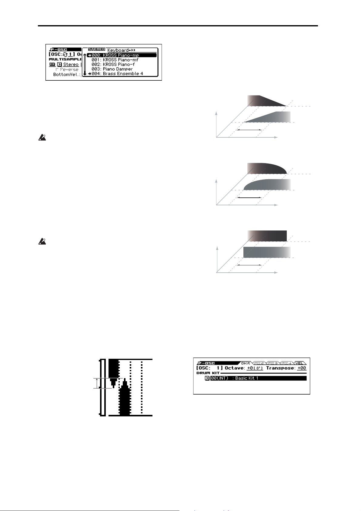
Program mode
Power, short for Equal Power, means that the two samples will
each be at around 70% of their full volume in the middle of the
crossfade. Sometimes, this may create a bump in the volume level,
in which case you might try selecting Linear instead.
Layer means that the two Multisamples will be layered together,
both at full volume, for the entire range of the crossfade.
Reverse [Off, On]
This plays the selected multisample in reverse without looping it.
Note: If an individual sample within the multisample is already set
to reverse, it will play in reverse without this setting.
On (checked): The multisample will play in reverse.
Off (unchecked): The multisample will play normally.
For some multisamples, this setting is not available.
Offset (Start Offset) [Off, 1st...4th]
In addition to simply starting playback from the beginning,
Multisamples can have up to 4 different pre-programmed alternate
starting points.
The Start Of fset option specifies whether to use the normal start
point (Off), or to use one of the alternate start points (1st–4th).
Some Multisamples may have fewer than 4 pre-programmed
points, in which case only the available points can be selected.
Level [000...127]
This sets the basic volume level of the multisample. The Amp
section can modify this basic level extensively with envelopes,
LFOs, keyboard tracking, and other modulation; for more
information, please see “8: P–Amp” on page 32.
Depending on the multisample, high Level settings may
cause distortion when playing many notes at a time. If this
occurs, lower the Level.
Bottom Vel. (Bottom Velocity) [001...127]
This sets the lowest velocity where the Multisample will sound.
Multisample1’s Bottom Vel. can be equal to, but not lower than,
that of Multisample2.
Xfade (Crossfade Range) [Off, 001...127]
This sets the range of velocities where Multisample1 will fade into
Multisample2, going up from the Bottom Vel..
For instance, if the Bottom Vel. is set to 64, and the Xade is set to
20, MS2 will start to fade in at velocities of 84 and below.
When velocities are within the Xfade, the Oscillator will use twice
as much polyphony as it would normally.
Note: You can only fade between two zones at once.
This shows the velocity zone.
Crossfade Curves
Linear
Volume
Power
Volume
Layer
Volume
MS2
MS1
Xfade
Velocity
MS2
MS1
Xfade
Velocity
MS2
MS1
Xfade
Velocity
Velocity Split
This shows the velocity zones for the oscillator’s four
multisamples and for each oscillator.
The meter on the left indicates the note-on velocity. This allows
you to verify the multisamples that will sound at each velocity.
Oscillator Mode Drums
This parameter appears when the Oscillator Mode is set to Drums
or Double Drums.
Xfade Range = 20
Curve = Linear
Bottom Velocity = 64
84
Curve [Linear, Power, Layer]
This controls the volume curve of the crossfade. Linear and
Power (short for Equal Power) let you fine-tune the way that the
two Multisamples mix together; one or the other may be more
appropriate for a given pair of Multisamples. Layer, true to its
name, lets you layer the two Multisamples together without any
crossfading.
Linear means that the two samples will each be at 50% of their
full volume in the middle of the crossfade. Sometimes, this may
create a dip in the volume level; if so, try using Power instead.
12
Drum Kit [000...031 (INT), 032...047 (USER), 048…056 (GM)]
This selects a drum kit.
Page 21
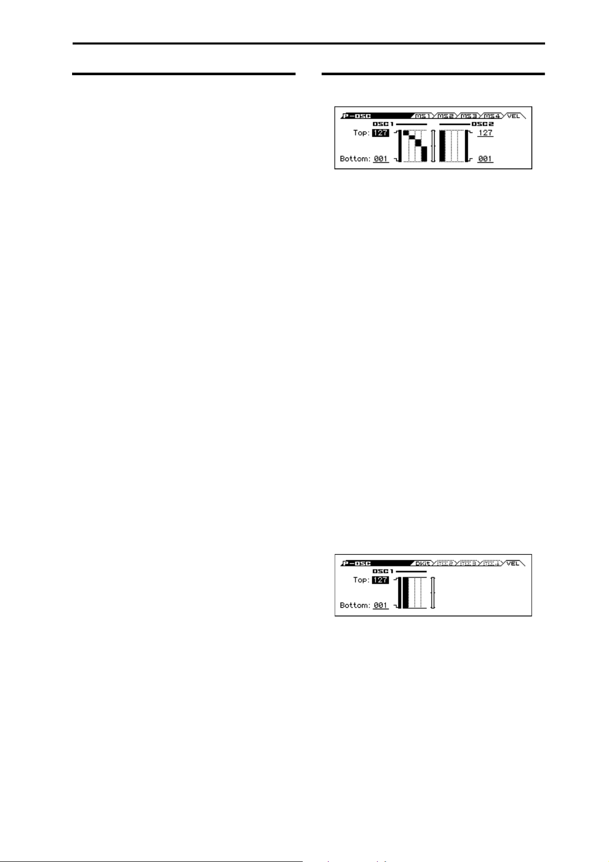
3: P–OSC 3–2: MS 2 (Multisample 2) 3–3: MS 3 (Multisample 3) 3–4: MS 4 (Multisample 4)
3–2: MS 2 (Multisample 2) 3–3: MS 3 (Multisample 3) 3–4: MS 4 (Multisample 4)
These are the multisample settings for Multisamples 2–4. The
parameters for Multisample 2 and 3 are exactly the same as those
for Multisample 1.
The parameters for Multisample 4 are also similar to those for
Multisample 1, except that Multisample 4 has no settings for
Bottom Vel. (Bottom Velocity) (which is always fixed at 1) and
Xfade (Crossfade Range).
3–5: VEL (Velocity Zone)
Here you can adjust the velocity zone for oscillators.
OSC1
Velocity can be used to switch between sounding oscillators 1 and
2. Here you can specify the velocity zone for oscillator 1.
This velocity zone setting takes priority over the velocity settings
of multisamples 1–8. The status of the settings is indicated by the
graph on the right side of the screen. This lets you adjust settings
while comparing them with the velocity split graph.
Top [001...127]
This sets the highest velocity where the Oscillator 1 will sound.
Note: The OSC1 Top velocity must be greater than the OSC1
Bottom velocity.
Bottom [001...127]
This sets the lowest velocity where the Oscillator 1 will sound.
Tips: You can also set the note value and velocity value by the
keyboard (see page 12 of the Operation Guide).
OSC2
Top [001...127]
This sets the highest velocity where the Oscillator 1 will sound.
Note: The OSC1 Top velocity must be greater than the OSC1
Bottom velocity.
Bottom [001...127]
This sets the lowest velocity where the Oscillator 1 will sound.
Tips: You can also set the note value and velocity value by the
keyboard (see page 12 of the Operation Guide).
Oscillator Mode Drums
Here you can specify the velocity zone for oscillator 1.
Top [001...127]
This sets the highest velocity where the Oscillator 1 will sound.
Note: The Top velocity must be greater than the Bottom velocity.
Tips: You can also set the note value and velocity value by the
keyboard (see page 12 of the Operation Guide).
Bottom [001...127]
This sets the lowest velocity where the Oscillator 1 will sound.
13
Page 22

Program mode
AMS Intensity
V
3–1...5: FUNCTION
•0: Write Program, Write/Initialize Program see page 63
•1: Solo Setting see page 63
•2: Compare see page 64
•3: Auto Song Setup see page 64
•4: Add to Favorite see page 64
•5: Copy Oscillator see page 64
•6: Swap Oscillator see page 64
For more information, please see the “Program: Function” section
on page 63.
4: P–PITCH
This page contains all of the settings for Oscillator 1’s pitch
modulation.
4–1: BASIC
Here, you can:
• Specify pitch bend being controlled by the pitch bend wheel (or
an incoming pitch bend message) set to independent Bend Up
and Bend Down, or controlled by an incoming message CC#16
(the ribbon control message etc).
• Use Pitch Slope to control how the pitch changes when you
play up and down the keyboard.
• Assign AMS modulation for pitch.
OSC (Oscillator Select) [1, 2]
Select the oscillator (1 or 2) that you want to edit.
Note: Oscillator 2 can be selected if Oscillator Mode is set to
Double.
Octave [–2[32'], –1[16'], +0[8'], +1[4']]
This sets the basic pitch of the Oscillator, in octaves. The default is
+0[8']. The standard octave of a multisample is +0 [8'].
Transpose [–12...+12]
This adjusts the pitch in semitones, over a range of ±1 octave.
Tune [–1200...+1200]
This adjusts the pitch in cents, over a range of ±1 octave. A cent is
1/100 of a semitone.
Offset (Frequency Offset) [–10.0Hz ... +10Hz]
This adjusts the pitch by increments of 0.1 Hz. Frequency Offset
is different from Tun e in that, when used to detune the two
oscillators, it can create a constant beat frequency across the range
of the keyboard.
CONTROLLERS
Bend (+) [–60...+12]
Specifies the amount of pitch change in semitone units that occurs
when you move the pitch bend wheel away from yourself (or when
a pitch bend message with a value of 1 or higher is received). For
normal pitch bend, set this to a positive value.
For example with a setting of +12, moving the pitch bend wheel
away from yourself will raise the pitch of the notes you've played,
by up to one octave.
14
Page 23
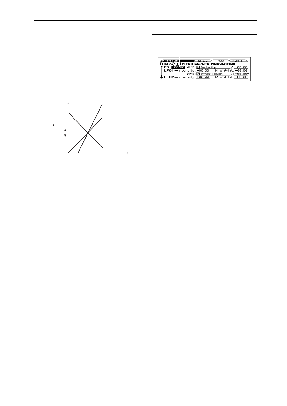
Bend (–) [–60...+12]
Pitch
Note on keyboard
2oct
1oct
1oct
C4 C5
+2
+1
0
–1
Specifies the amount of pitch change in semitone units that occurs
when you move the pitch bend wheel toward yourself (or when a
pitch bend message with a value of -1 or lower is received). For
normal pitch bend, set this to a negative value.
For example with a setting of –60, moving the pitch bend wheel
toward yourself will lower the pitch of the notes you've played, by
up to five octaves.
4: P–PITCH 4–2: MOD (Modulation)
4–2: MOD (Modulation)
EG Intensity
Pitch Slope [–1.0...+2.0]
Normally, this should be set to the default of +1.0.
Pitch Slope, pitch, and note
Positive (+) values cause the pitch to rise as you play higher on the
keyboard, and negative (–) values cause the pitch to fall as you
play higher on the keyboard.
When this is set to 0, playing different notes on the keyboard won’t
change the pitch at all; it will be as if you’re always playing C4.
This can be useful for special effects sounds, for instance.
Ribbon (#16) [–12...+12]
Specify in semitones how the pitch will change when CC#16 is
received.
With a positive (+) setting, the pitch will rise when the value of
CC#16 is higher than the center value of 64. With a negative (–)
setting, the pitch will fall.
AMS (Pitch) [List of AMS Sources]
This selects an AMS source to control the pitch. For a list of AMS
sources, please see “AMS (Alternate Modulation Source) List” on
page 282.
Intensity [–12.00...+12.00]
This controls the depth and direction of the pitch modulation, in
semitones.
For example if you set AMS (Pitch) to M.Wheel #01 and then
move the modulation wheel away from yourself, the pitch will rise
if this parameter is set to a positive (+) value, or fall if this
parameter is set to a negative (–) value.
AMS Intensity
You can set up initial amounts of pitch modulation from the Pitch
EG and LFO1/2, as well as AMS modulation of LFO and EG
amounts.
OSC (Oscillator Select) [1, 2]
Select the oscillator (1 or 2) that you want to edit.
Note: Oscillator 2 can be selected if Oscillator Mode is set to
Double.
EG
EG Intensity [–12.00...+12.00]
This controls the initial effect of the Pitch EG on Oscillator 1’s
frequency, in half-steps, before any AMS modulation.
The Pitch EG’s shape can swing all the way from +99 to –99.
When the Intensity is set to a positive (+) value, positive values
from the EG raise the pitch, and negative values lower the pitch.
When the Intensity is set to a negative (–) value, the effect of the
EG is reversed; positive EG values mean lower pitches, and
negative EG values mean higher pitches.
AMS (Pitch EG) [List of AMS Sources]
This selects any AMS modulation source to scale the amount of
the Pitch EG.
For a list of AMS sources, please see “AMS (Alternate
Modulation Source) List” on page 282.
AMS Intensity [–12.00...+12.00]
This controls the depth and direction of the pitch EG AMS
modulation. The AMS modulation and the initial Intensity are
added together to determine the Pitch EG’s final effect.
With positive (+) values, greater modulation will increase the
effect of the Pitch EG, as shown in example B below.
With negative (–) values, greater modulation will introduce the
opposite effect of the Pitch EG–like inverting the polarity of the
envelope. You can use this in several different ways:
• You can set an initial positive amount with the Intensity
parameter, and then reduce this amount with AMS. In this case,
the final effect of the EG is simply diminished, and not actually
inverted, as shown in example C.
• You can also set the AMS Intensity amount to be greater than
the initial Intensity. In this case, the EG will have a positive
effect with low modulation amounts, and an inverted effect at
higher modulation amounts as shown in example D.
15
Page 24

Program mode
Pitch EG AMS
A. Original EG B. Intensity = +6.00
Change
to Pitch
C. Intensity = –3.00
Change
to Pitch
D. Intensity = –24.00
LFO1
LFO1 and LFO2 can both control the pitch. You can control the
strength of each LFO’s modulation in three different ways:
• Set an initial amount of LFO modulation, using the LFO1 Int.,
LFO2 Int. parameters.
•Use M.Whl-Int to adjust the amount of LFO that is applied
when you use the modulation wheel.
• Use any AMS source to scale the amount of the LFO.
The results are added together to produce the total LFO effect.
LFO1 Intensity [–12.00...+12.00]
This controls the initial effect of the LFO on the pitch, in
semitones, before any M.Whl-Int or AMS modulation.
Negative (–) settings will invert the phase of the LFO.
LFO1 Int., M.Whl-Int, and AMS (LFO1) settings are summed to
determine the depth and direction of pitch modulation produced by
OSC1 LFO1.
LFO2
The parameters for LFO2 are identical to those for LFO1. For
more information, please see the descriptions under LFO1, above.
M.Whl-Int (Modulation Wheel Intensity) [–12.00...+12.00]
Specify the depth of pitch modulation produced by OSC1 LFO1
when the modulation wheel is moved away from yourself (or when
CC#1 is received).
This parameter sets the maximum amount of LFO modulation
added by M.Whl-Int, in semitones.
As this value is increased, moving the modulation wheel away
from yourself will cause the OSC1 LFO1 to produce deeper pitch
modulation.
Negative (–) settings will invert the phase of the LFO. You can
also use this to reduce the initial amount of the LFO, as set by
LFO1 Int., above.
For example:
1. Set LFO1 Int. to +7.00.
The LFO will now have a fairly strong effect on the pitch, bending
it by a perfect 5th.
2. Set M.Whl-Int to –7.00.
Moving the modulation wheel away from yourself will decrease
the effect of the LFO. If you move the wheel all the way, the LFO
will be cancelled, and no modulation will be applied.
AMS (LFO1) [List of AMS Sources]
This selects any AMS modulation source to scale the amount of
the LFO applied to pitch.
For a list of AMS sources, please see “AMS (Alternate
Modulation Source) List” on page 282.
AMS Intensity [–12.00...+12.00]
This controls the depth and direction of the AMS (LFO1)
modulation for pitch.
With a setting of 0, modulation will not be applied. With a setting
of 12.00, the OSC1 LFO1 will apply a maximum of
+/–1 octave of pitch modulation.
For example if you play the keyboard with AMS (LFO1) set to
Filter EG, pitch modulation will be stronger when the Filter
envelope value is higher. If this has a positive (“+”) value, pitch
modulation via OSC1 LFO1 is applied at normal phase; if it has a
negative (“-”) value, the phase is inverted.
16
Page 25

4: P–PITCH 4–3: PORTA (Portamento)
4–3: PORTA (Portamento)
Here you can set up Portamento.
OSC (Oscillator Select) [1, 2]
Select the oscillator (1 or 2) that you want to edit.
Note: Oscillator 2 can be selected if Oscillator Mode is set to
Double.
PORTAMENTO
Portamento lets the pitch glide smoothly between notes, instead of
changing abruptly.
Enable [Off, On]
On (checked): Turns on Portamento, so that pitch glides smoothly
between notes.
Off (unchecked): Turns off Portamento. This is the default state.
Fingered [Off, On]
This parameter allows you to control Portamento through your
playing style. When it’s enabled, playing legato will turn on
Portamento, and playing detached will turn it off again.
This option is only available when Portamento Enable is turned
on.
On (checked): Turns on Fingered Portamento.
Off (unchecked): Turns off Fingered Portamento.
4–1...3: FUNCTION
•0: Write Program, Write/Initialize Program see page 63
•1: Solo Setting see page 63
•2: Compare see page 64
•3: Auto Song Setup see page 64
•4: Add to Favorite see page 64
•5: Copy Oscillator see page 64
•6: Swap Oscillator see page 64
For more information, please see the “Program: Function” section
on page 63.
Mode [Rate, Time]
Rate means that Portamento will always take the same amount of
time to glide a given distance in pitch - for instance, one second
per octave. Put another way, gliding several octaves will take
much longer than gliding a half-step.
Time means that Portamento will always take the same amount of
time to glide from one note to another, regardless of the difference
in pitch. This is especially useful when playing chords, since it
ensures that each note in the chord will end its glide at the same
time.
Time [000...127]
This controls the portamento time. Higher values mean longer
times, for slower changes in pitch.
This option is only available when Portamento Enable is turned
on.
Assigning SW1 or SW2 to Portamento On/Off
You can turn portamento on/off by using the two assignable
switches SW1 and SW2.
To do so:
1. Go to the P–INPUT/CTRL>CONTROLLERS page.
2. Under Panel Switch Assign, set either SW1 or SW2 to
Porta.SW (CC#65).
Now, the selected switch will enable and disable Portamento.
If you assign portamento to SW1/2, MIDI portamento
controller #65 will be transmitted each time you use the
switch. You can also turn portamento on/off by receiving
MIDI controller #65.
17
Page 26
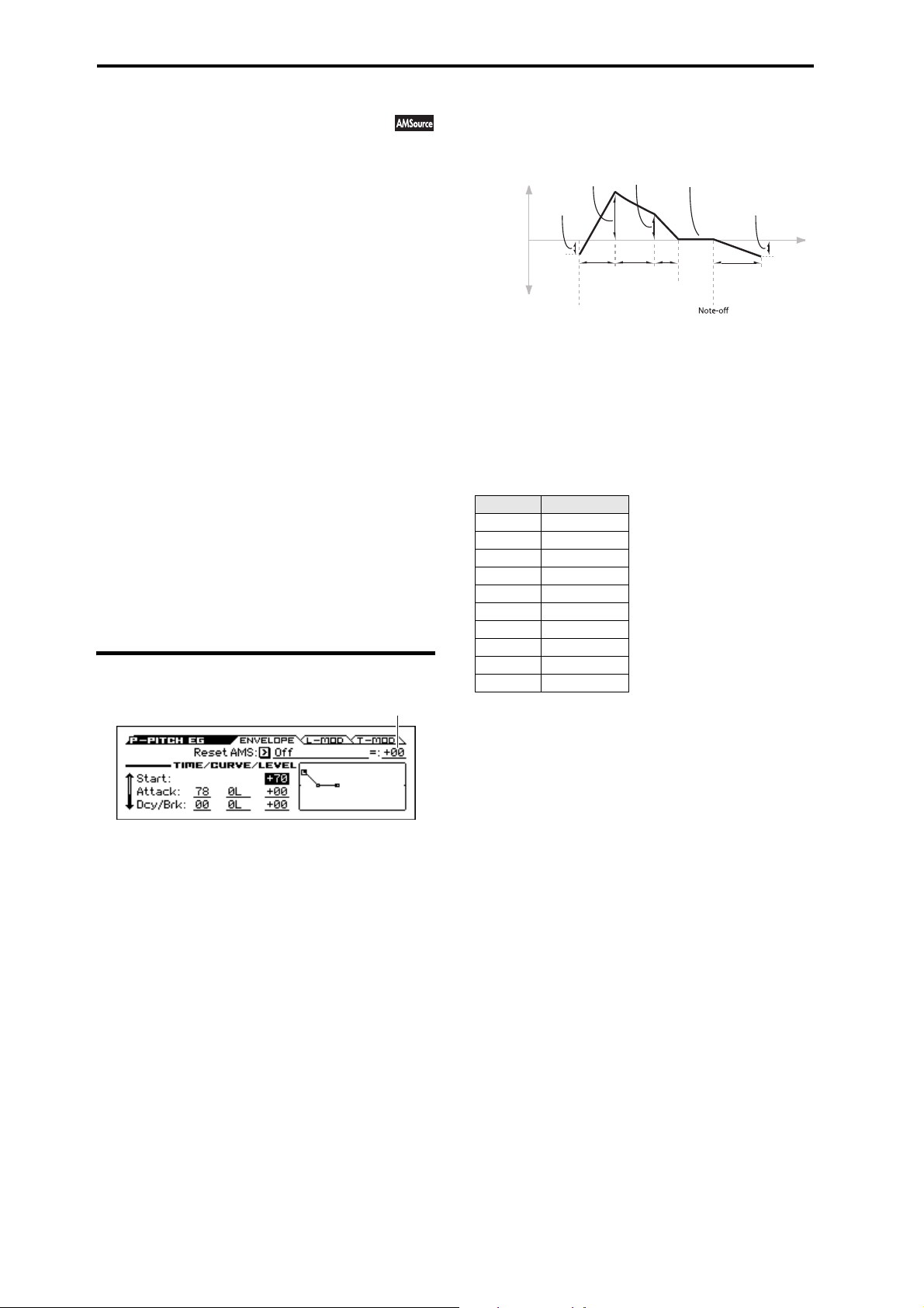
Program mode
Threshold
5: P–PITCH EG (Pitch Envelope)
The Pitch EG, or Envelope Generator, lets you create complex,
time-varying changes to the pitch of Oscillators 1 and 2. The
parameters on this page control the shape of the EG. For instance,
you can:
• Create the basic EG shape by setting the levels and times of
each segment.
• Control the curvature of each EG segment, for subtle control
over the modulation time of the EG.
• Set up complex modulation of EG levels and times.
• Set up an AMS source, such as an LFO, to restart the EG.
To control how much effect the EG has on the pitch, use the Pitch
EG parameters on the P–PITCH>MOD page, as described under
“4–2: MOD (Modulation)” on page 15.
Differences from the other EGs
The Pitch EG is different from the Filter and Amp EGs in several
ways:
• The single Pitch EG is shared by both Oscillator 1 and
Oscillator 2.
• The Sustain level is always 0.
• The Level modulation has two AMS sources instead of one, and
the Time modulation has one AMS source instead of three.
Pitch EG is also an AMS source
You can use the Pitch EG as an AMS source to modulate other
parameters, just like the keyboard tracking and LFOs. Simply
select the Pitch EG in the AMS list for the desired parameter.
5–1: ENVELOPE
TIME/CURVE/LEVEL
Pitch EG
Change to
Pitch
Attack
Level
Start
Level
Attack
Time
Note-on or reset
Break
Level
Decay
Time
Sustain Level
(Always 0)
Slope
Time
Release
Time
Release
Level
Time
The envelope moves to a specified level over the specified time,
and then moves to the next specified level over the specified time.
It produces a modulation signal corresponding to this movement.
The parameters below let you set four levels, the amount of time it
takes to go from each of the levels to the next, and the shape (from
linear to curved) of each transition.
Time
Higher values mean longer times, as shown below:
EG Value Actual Time
10 10 ms
20 44 ms
30 104 ms
40 224 ms
50 464 ms
60 944 ms
70 1.8 seconds
80 3.8 seconds
90 10.9 seconds
99 87.3 seconds
Reset AMS (EG Reset AMS) [List of AMS Sources]
This selects an AMS source to reset the EG to the start point. For
instance, you can use a tempo-synced LFO to trigger the EG in a
repeating rhythm. This reset is in addition to the initial note-on,
which always causes the EG to start.
For a list of AMS sources, please see “AMS (Alternate
Modulation Source) List” on page 282.
Threshold [–99...+99]
This sets the AMS level which will trigger the EG reset. Among
other things, you can use this to adjust the exact point in an LFO’s
phase where the EG will be reset, effectively controlling its
“groove” against other rhythmic effects.
When the threshold is positive, the EG triggers when passing
through the threshold moving upwards. When the threshold is
negative, the EG triggers when passing through the threshold
moving downwards.
Note: For several LFO waveform types, or if the LFO cycle is fast,
the LFO output may not always keep up with high values such as
+99 or –99.
18
Attack [00...99]
This sets how long the EG takes to move from the Start level to the
Attack level.
For the fastest possible attack time, you can set the Start level to
+99; in this case, the EG will start instantaneously at its maximum
value.
Dcy/Brk (Decay) [00...99]
This sets the time it takes to move from the Attack level to the
Break level.
Slope [00...99]
This sets how long the EG takes to move from the Break level to
the Sustain level (which for the Pitch EG is always 0). Once it
reaches the Sustain level, the EG will stay there until note-off,
unless it is reset via AMS.
Release [00...99]
This sets how long it takes the EG to move from the Sustain level
to the Release level.
Curve
For the sake of simplicity, most of the diagrams in this manual
show envelopes as being made out of straight lines. In actuality,
though, envelopes are more likely to be made out of curves.
In other words, each segment’s level will change quickly at first,
and then slow down as it approaches the next point. This tends to
sound better than straight, linear segments.
Classic analog synth envelopes made these curved shapes
naturally. The KROSS goes a step further than vintage synths,
however, and lets you control the amount of curvature separately
for each of the four envelope segments.
Page 27
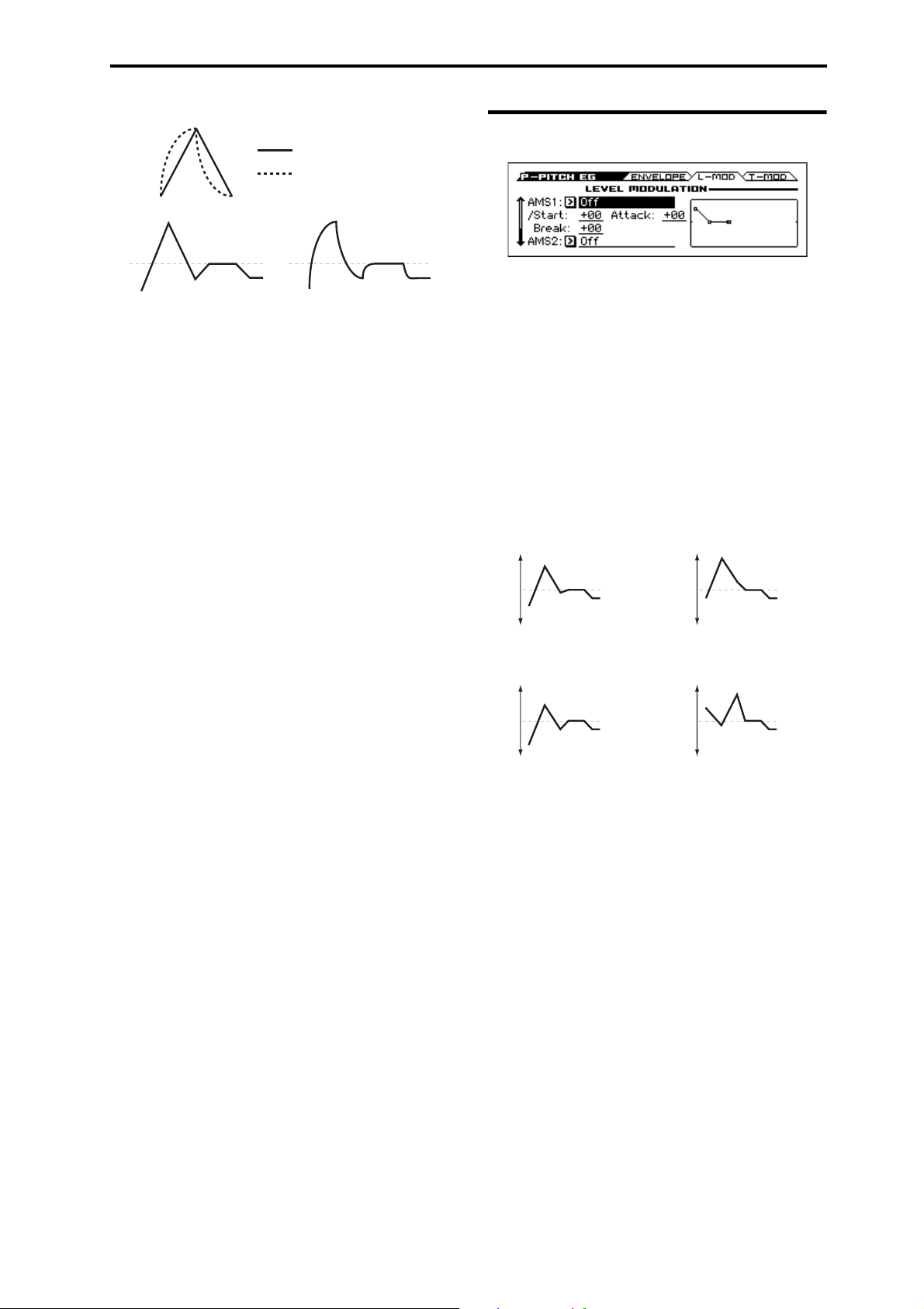
5: P–PITCH EG (Pitch Envelope) 5–2: L-MOD (Level Modulation)
Curve = 0 (Linear)
Curve = 0 (Linear)
Curve = 10 (Exp/Log)
Curve = 10 (Exp/Log)
Original Shape
Positive AMS on Start and Break,
Negative AMS on Attack
Negative AMS on Start,
Attack, and Break
Positive AMS on Start,
Attack, and Break
Pitch EG Curve
When you change the curvature, the EG times remain the same.
However, greater curvature will tend to sound faster, because the
value changes more quickly at the beginning.
Different curve settings for up and down
You may find that different amounts of curvature are suitable for
segments which go up and segments which go down.
For instance, a curve of 3 is a good default setting for upward
segments, such as Attack. On the other hand, a curve of 6 or more
is good for downward segments, such as Decay and Release.
Attack [0L (Linear), 1...9, 10E (Exp/Log)]
This sets the curvature of the Attack segment - the transition from
the Start level to the Attack level.
5–2: L-MOD (Level Modulation)
These settings let you use two different AMS sources to control
the Level parameters of the EG. For each of the two AMS sources,
the Start, Attack, Decay, and Break levels each have their own
modulation intensities.
By using different settings for each of the three levels, you can
cause both subtle and dramatic changes to the EG shape, as shown
below.
Note: Once the EG has started a segment between two points, that
segment can no longer be modulated. This includes both the time
of the segment, and the level reached at the end of the segment.
For instance, if the EG is in the middle of the Decay time, you can
no longer modulate either the Decay time or the Break level.
This also means that modulating the Start level, Attack level, or
Attack time will not affect notes that are already sounding, unless
the EG is then re-started via EG Reset.
Pitch EG Level Modulation
Dcy/Brk (Decay) [0L (Linear), 1...9, 10E (Exp/Log)]
This sets the curvature of the Decay segment - the transition from
the Attack level to the Break level.
Slope [0L (Linear), 1...9, 10E (Exp/Log)]
This sets the curvature of the Slope segment - the transition from
the Break level to the Sustain level (which for the Pitch EG is
always 0).
Release [0L (Linear), 1...9, 10E (Exp/Log)]
This sets the curvature of the Release segment - the transition from
the Sustain level to the Release level.
Level
Each of the four levels can be either positive or negative.
Positive levels will make the pitch (or other AMS destination) go
up from its programmed value; negative levels will make it go
down.
Note that, unlike the Filter and Amp EGs, the Pitch EG’s Sustain
Level is always 0.
Start [–99...+99]
This sets the initial level at note-on.
Attack [–99...+99]
This sets the level at the end of the Attack time.
Dcy/Brk (Break) [–99...+99]
Break, short for Break Point, sets the level at the end of the Decay
time.
Release [–99...+99]
This sets the level at the end of the Release time.
AMS1
AMS1 [List of AMS Sources]
This selects the first AMS source to control the EG’s Level
parameters.
For a list of AMS sources, please see “AMS (Alternate
Modulation Source) List” on page 282.
Start [–99...+99]
This controls the depth and direction of the AMS modulation for
the Start level.
For example, if you set the AMS1 source to Velocity and set St to
+99, the Start level will increase as you play harder. If you instead
set St to –99, the Start level will decrease as you play harder.
Attack [–99...+99]
This controls the depth and direction of the AMS modulation for
the Attack level.
Break [–99...+99]
This controls the depth and direction of the AMS modulation for
the Break level.
19
Page 28
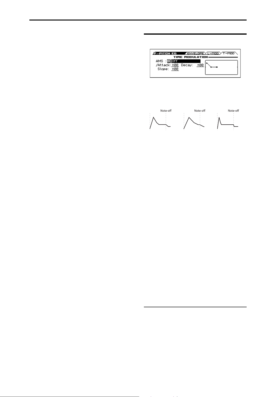
Program mode
AMS=Velocity, Intensity = a positive (+) value
“Attack”= +
“Decay”= +
“Slope”= +
“Attack”= +
“Decay”= +
“Slope”= +
“Attack”= –
“Decay”= –
“Slope”= –
Softly played note.
Original Shape.
Strongly played note.
Times are longer.
Reaches Sustain more
slowly.
Strongly played note.
Times are shorter.
Reaches Sustain more
quickly.
Note-on Note-on Note-on
AMS2
This selects the second AMS source for controlling the EG’s Level
parameters. The parameters ofAMS2 are identical to those of
AMS1, above.
5–3: T-MOD (Time Modulation)
These settings let you use an AMS source to control the Time
parameters of the EG. The Attack, Decay, and Slope times share
this AMS source, but each has its own modulation intensity.
Pitch EG Time Modulation
AMS1
AMS [List of AMS Sources]
This selects the AMS source to control the EG’s Time parameters.
Velocity and Keyboard Track can both be useful here for instance.
For a list of AMS sources, please see “AMS (Alternate
Modulation Source) List” on page 282.
Attack [–99...+99]
This controls the depth and direction of the AMS modulation for
the Attack time.
For example, if you set the AMS source to Velocity and set Attack
to +99, the Attack time will get much longer at higher velocities. If
you instead set Attack to –99, the Attack time will get much
shorter at higher velocities.
When the AMS source is at its maximum value for instance, when
Ve lo ci ty is at 127 a setting of +8 will make the Attack time almost
twice as long, and a setting of –8 will cut the Attack time almost in
half.
Decay [–99...+99]
This controls the depth and direction of the AMS modulation for
the Decay time.
Slope [–99...+99]
This controls the depth and direction of the AMS modulation for
the Slope time.
20
V
5–1...3: FUNCTION
•0: Write Program, Write/Initialize Program see page 63
•1: Solo Setting see page 63
•2: Compare see page 64
•3: Auto Song Setup see page 64
•4: Add to Favorite see page 64
•5: Copy Oscillator see page 64
•6: Swap Oscillator see page 64
For more information, please see the “Program: Function” section
on page 63.
Page 29
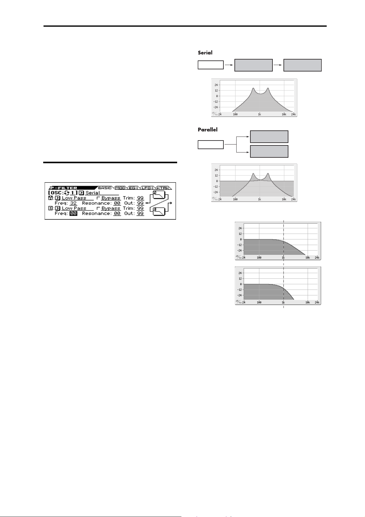
6: P–FILTER 6–1: BASIC
Filter A (Low Pass)Oscillator Filter B (High Pass)
Oscillator
Filter A (Low Pass)
Filter B (High Pass)
6: P–FILTER
Filtering can make subtle or dramatic changes to the oscillator’s
timbre. Each oscillator has two multimode resonant filters, A and
B, as well as a dedicated filter envelope and keyboard tracking
generator.
These pages let you control all aspects of the filters. Among other
things, you can:
• Adjust basic settings for each oscillator’s filters, including
routing, modes, cutoff, resonance, etc.
• Set up filter modulation, including keyboard tracking, the filter
envelope, LFO modulation, and AMS control.
Note that when the Oscillator Mode is set to Single, only
Oscillator 1’s filters are active; the pages for Oscillator 2’s filters
will be grayed out.
6–1: BASIC
Serial and Parallel Routing
12db/oct / 24db/oct
This page contains all of the basic settings for Oscillator 1’s Filter
A and Filter B. For example, you can:
• Set up the filters to produce a single 12 dB/oct filter, dual
12 dB/oct filters in either serial or parallel routing, or a single
24 dB/oct filter.
• Set each of the two filters to Low Pass, High Pass, Band Pass,
or Band Reject modes.
• Set the cutoff, resonance, and input and output levels of each
filter, including modulation of resonance and output level.
OSC (Oscillator Select) [1, 2]
Select the oscillator (1 or 2) that you want to edit.
Note: Oscillator 2 can be selected if Oscillator Mode is set to
Double.
Filter Routing [Single, Serial, Parallel, 24dB(4Pole)]
Each oscillator has two filters, Filter A and Filter B. This
parameter controls whether one or both of the filters are used, and
if both are used, it controls how they are connected to each other.
Single. This uses only Filter A as a single 2-pole, 12 dB/octave
filter (6 dB/oct for Band Pass and Band Reject). When this option
is selected, the controls for Filter B will be grayed out.
Serial. This uses both Filter A and Filter B. The oscillator first
goes through Filter A, and then the output of Filter A is processed
through Filter B.
Parallel. This also uses both Filter A and Filter B. The oscillator
feeds both filters directly, and the outputs of the two filters are then
summed together.
24dB/oct. This merges both filters to create a single 4-pole, 24 dB/
octave filter (12 dB/oct for Band Pass and Band Reject). In
comparison to Single, this option produces a sharper roll-off
beyond the cutoff frequency, as well as a slightly more delicate
resonance. Many classic analog synths used this general type of
filter.
When 24 dB/oct is selected, only the controls for Filter A are
active; the controls for Filter B will be grayed out.
Low Pass:
12dB/oct
Low Pass:
24dB/oct
A (Filter A)
Type (Filter Type) [Low Pass (12dB/oct), High Pass (12dB/oct),
Band Pass (6dB/oct), Band Reject (6dB/oct)]
The filter will produce very different results depending on the
selected filter type. The selections will change slightly according
to the selected Filter Routing, to show the correct cutoff slope in
dB per octave.
Low Pass (12dB/oct). This cuts out the parts of the sound which
are higher than the cutoff frequency. Low Pass is the most
common type of filter, and is used to make bright timbres sound
darker.
High Pass (12dB/oct). This cuts out the parts of the sound which
are lower than the cutoff frequency. You can use this to make
timbres sound thinner or more buzzy.
Band Pass (6dB/oct). This cuts out all parts of the sound, both
highs and lows, except for the region around the cutoff frequency.
Since this filter cuts out both high and low frequencies, its effect
can change dramatically depending on the cutoff setting and the
oscillator’s multisample.
With low resonance settings, you can use the Band Pass filter to
create telephone or vintage phonograph sounds. With higher
resonance settings, it can create buzzy or nasal timbres.
21
Page 30
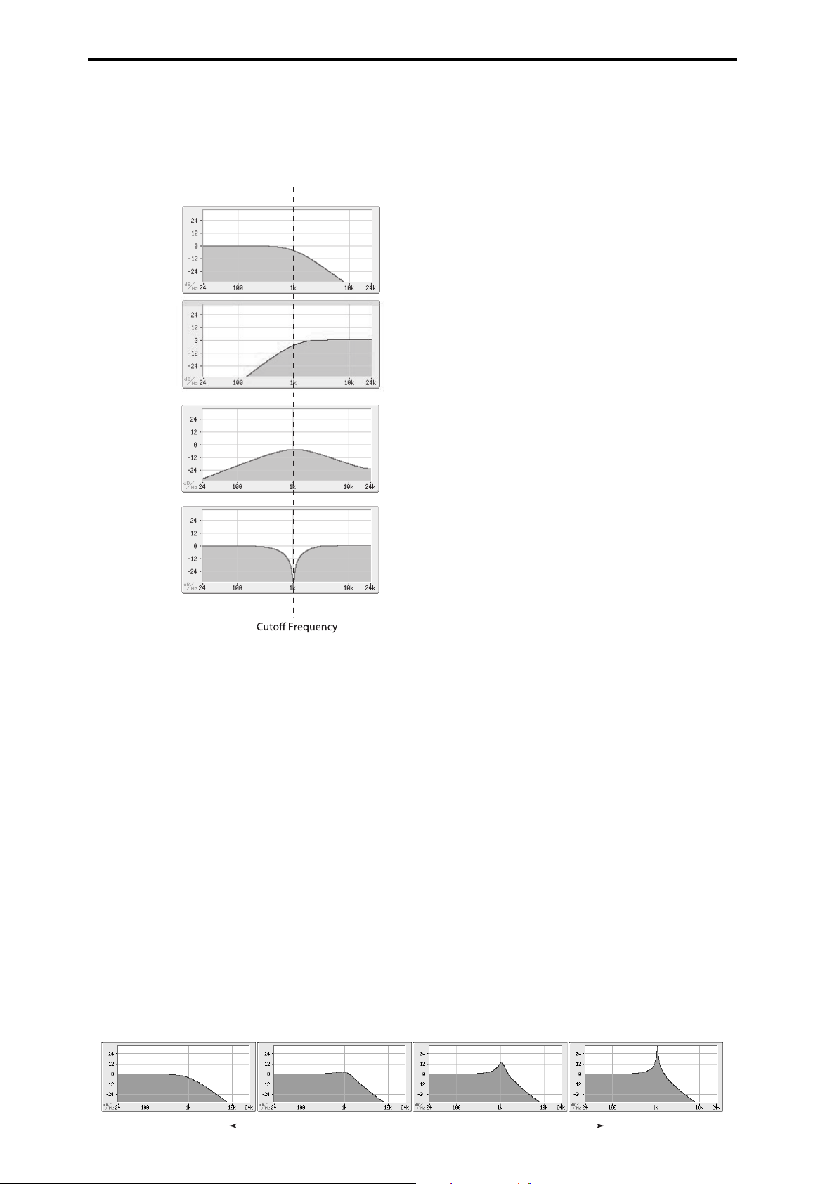
Program mode
Low Pass
High Pass
Band Pass
Band Reject
Resonance
Band Reject (6dB/oct). This filter type also called a notch filter–
cuts only the parts of the sound directly around the cutoff
frequency. Try modulating the cutoff with an LFO to create
phaser-like effects.
Filter Types and Cutoff Frequency
To make the resonance track the keyboard pitch, please see “Key
Follow” on page 27.
Out (Output) [00...99]
This controls the output level of Filter A. You can use this to
balance the volumes of Filters A and B when the Routing is set to
Parallel, or to turn down the volume to avoid clipping later in the
signal chain.
B (Filter B)
Filter B is available when the Filter Routing is set to Serial or
Parallel. Otherwise, the parameters in this section will be grayed
out.
The parameters for Filter B are identical to those for Filter A. For
more information, please see the descriptions under Filter A,
above.
Bypass [Off, On]
This lets you bypass Filter A completely.
If Bypass is Off, Filter A functions normally.
When Bypass is On, Filter A will have no effect.
Trim (Input Trim) [00...99]
This adjusts the volume level at the input to the filter. If you notice
that the sound is distorting, especially with high Resonance
settings, you can turn the level down here or at the Output.
Freq (Cutoff Frequency) [00...99]
This controls the cutoff frequency of Filter A, in increments of 1/
10 of an octave. The specific effect of the cutoff frequency will
change depending on the selected Filter Type.
Resonance [00...99]
Resonance emphasizes the frequencies around the cutoff
frequency.
When this is set to 0, there is no emphasis, and frequencies beyond
the cutoff will simply diminish smoothly.
At medium settings, the resonance will alter the timbre of the
filter, making it sound more nasal, or more extreme.
At very high settings, the resonance can be heard as a separate,
whistling pitch.
Low resonance value High resonance value
22
Page 31

6–2: MOD (Modulation)
AMS Intensity
Here you can adjust settings for the modulation that controls the
filter. You can use any AMS source to control the cutoff frequency
and resonance of each filter.
OSC (Oscillator Select) [1, 2]
Select the oscillator (1 or 2) that you want to edit.
Note: Oscillator 2 can be selected if Oscillator Mode is set to
Double.
6: P–FILTER 6–2: MOD (Modulation)
Output
AMS [List of AMS Sources]
This selects a modulation source to control the output level of
Filter A. For a list of AMS sources, please see “AMS (Alternate
Modulation Source) List” on page 282.
AMS Int. [–99...+99]
This controls the depth and direction of the output level
modulation.
B (Filter B)
The parameters for Filter B are identical to those for Filter A. For
more information, please see the descriptions under Filter A,
above.
A (Filter A)
Frequency
AMS1 [List of AMS Sources]
This selects the first modulation source for controlling Filter A’s
cutoff frequency. For a list of AMS sources, please see “AMS
(Alternate Modulation Source) List” on page 282.
AMS Intensity (Cutoff AMS1 Intensity) [–99...+99]
This controls the depth and direction of AMS1.
AMS2 [List of AMS Sources]
This selects the second modulation source for controlling Filter A’s
cutoff frequency. For a list of AMS sources, please see “AMS
(Alternate Modulation Source) List” on page 282.
AMS Intensity (Cutoff AMS2 Intensity) [–99...+99]
This controls the depth and direction of AMS2.
Resonance
AMS [List of AMS Sources]
This selects a AMS source to control the Resonance amount. For a
list of AMS sources, please see “AMS (Alternate Modulation
Source) List” on page 282.
AMS Intensity [–99...+99]
This controls the depth and direction of the Resonance
modulation.
For example, if Velocity has been selected, changes in keyboard
velocity will affect the resonance. With positive (+) values, the
resonance will increase as you play more strongly, and as you play
more softly the resonance will approach the level specified by the
Resonance setting. With negative (–) values, the resonance will
decrease as you play more strongly, and as you play more softly
the resonance will approach the level specified by the Resonance
setting.
The resonance level is determined by adding the Resonance and
AMS Int. values.
23
Page 32

Program mode
B. Velocity to A = +50
C. Velocity to A = –25 D. Velocity to A = –99
In all examples below, Intensity to A = +50
Original
Original
A. Original EG
6–3: EG-I (EG Intensity)
Here you can specify the modulation that controls the amount of
effect that the filter EG has on the cutoff frequency. For example
you can specify how velocity controls the way that the EG changes
the cutoff frequency.
The total modulation that's specified on this page will be the
amount of EG that's actually applied to the cutoff frequency.
Intensity to A [–99...+99]
This controls the initial effect of the Filter EG on Filter A’s cutoff
frequency, before any velocity or AMS modulation.
The Filter EG’s shape can swing all the way from +99 to –99.
Positive values increase the cutoff frequency, and negative values
decrease the cutoff frequency. For instance, please see the graphic
“Velocity control of Filter EG” above. The EG shape in example A
rises up at first, and then falls below 0 towards the end.
When Intensity to A is set to a positive (+) value, the EG’s effect
will match its shape. When the EG rises above 0, the cutoff
frequency will increase.
With negative (–) values, the effect will be in the opposite
direction; when the EG rises above 0, the filter cutoff will
decrease.
Note: To set up the EG itself, including attack and release times,
levels, and so on, please see “7: P–FILTER EG (Filter Envelope)”
on page 28.
OSC (Oscillator Select) [1, 2]
Select the oscillator (1 or 2) that you want to edit.
Note: Oscillator 2 can be selected if Oscillator Mode is set to
Double.
Velocity to A [–99...+99]
This lets you use velocity to scale the amount of the Filter EG
applied to Filter A.
Velocity control of Filter EG
Intensity to B [–99...+99]
This controls the initial effect of the Filter EG on Filter B’s cutoff
frequency, before any velocity or AMS modulation. For more
information, please see “Intensity to A” above.
AMS (Filter EG AMS) [List of AMS Sources]
This selects any AMS modulation source to scale the amount of
the Filter EG that’s applied to Filters A and B. The two filters
share a single AMS source, with separate intensity settings.
Otherwise, the AMS modulation will work in the same way as the
Velocity to A parameter, described above.
For a list of AMS sources, please see “AMS (Alternate
Modulation Source) List” on page 282.
Int to A (AMS Intensity to A) [–99...+99]
This controls the depth and direction of the EG AMS modulation
for Filter A.
Int to B (AMS Intensity to B) [–99...+99]
This controls the depth and direction of the EG AMS modulation
for Filter B.
With positive (+) values, playing more strongly will increase the
effect of the Filter EG, as shown in example B above.
With negative (–) values, playing more strongly will introduce the
opposite effect of the Filter EG–like inverting the polarity of the
envelope. You can use this in several different ways:
• You can set an initial positive amount with the Intensity to A/B
parameters, and then reduce this amount with velocity. In this
case, the final effect of the EG is simply diminished, and not
actually inverted, as shown in example C above.
• You can also set the Velocity to A/B amounts so that they are
greater than the initial amounts of Intensity to A/B. In this case,
the EG will have a positive effect at low velocities, and an
inverted effect at high velocities as shown in example D.
Velocity to B [–99...+99]
This lets you use velocity to scale the amount of the Filter EG
that’s applied to Filter B. For more information, please see
“Velocity to A” above.
24
Page 33
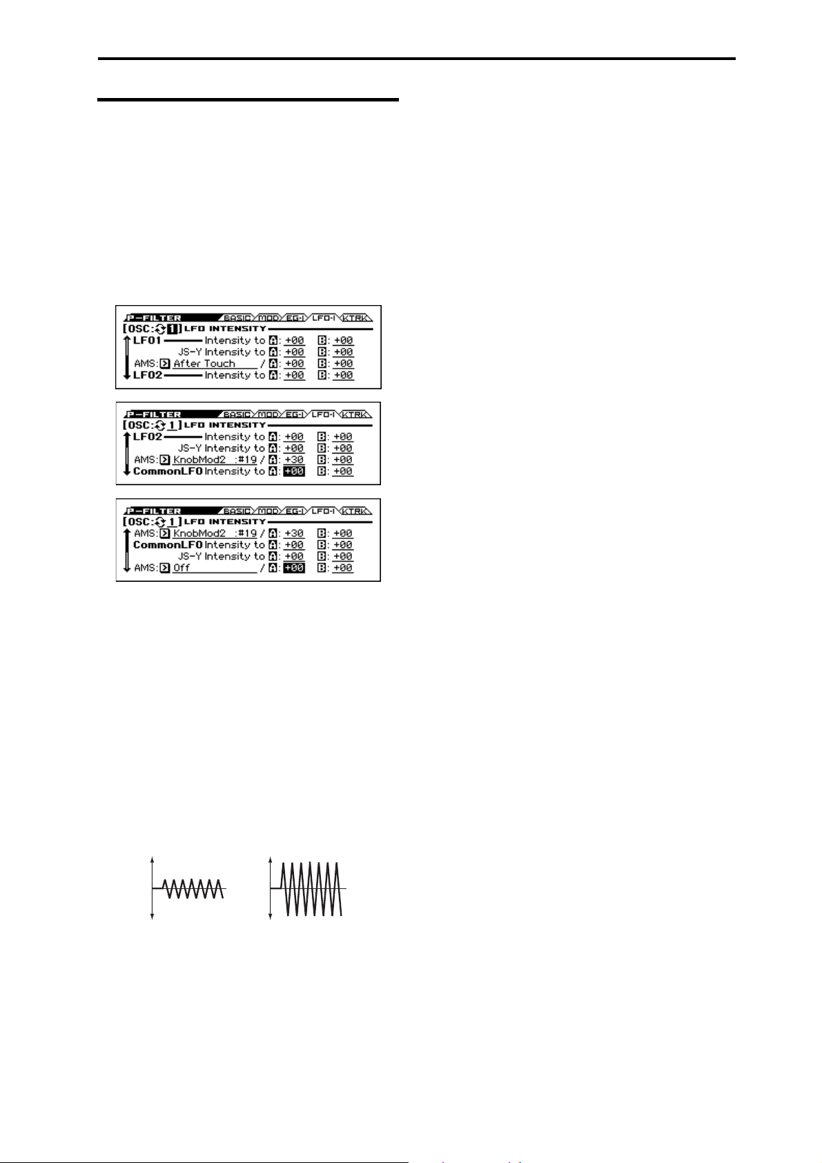
6–4: LFO-I (LFO Intensity)
Low setting High setting
LFO1, LFO2, and the Common LFO can all modulate Filter A and
B’s cutoff frequencies. You can control the strength of each LFO’s
modulation independently for each filter, in three different ways:
• Set an initial amount of LFO modulation, using the Intensity to
A and B parameters.
• Use JS-Y to scale the amount of the LFO.
• Use any AMS source to scale the amount the LFO.
You can use each of these methods for each of the three LFOs, and
do so separately for both Filter A and Filter B. The results are
added together to produce the total LFO effect.
6: P–FILTER 6–4: LFO-I (LFO Intensity)
JS–Y Intensity to A [–99...+99]
This adjusts the depth by which the LFO will modulate the cutoff
frequency of filter A when CC#2 is received.
Note: The -Y direction of joystick control is called “JS-Y.”
Although a joystick is a controller that's provided on many Korg
instruments, the KROSS is not equipped with a joystick.
Negative (–) settings will invert the phase of the LFO. You can
also use this to reduce the initial amount of the LFO, as set by
Intensity to A, above. For example:
1. Set Intensity to A to +50.
The LFO will now have a fairly strong effect on the filter cutoff.
2. Set JS-Y Intensity to A to –50.
Now, if you move the joystick down, the effect of the LFO will
fade away. When the joystick is all the way at the bottom of its
range, the LFO will be completely cancelled out.
JS–Y Intensity to B (LFO1) [–99...+99]
This lets you use JS-Y to scale the amount of the LFO applied to
Filter B.
AMS (LFO1) [List of AMS Sources]
This selects any AMS modulation source to scale the amount of
the LFO applied to Filters A and B. The two filters share a single
AMS source, but with separate intensity settings.
For a list of AMS sources, please see “AMS (Alternate
Modulation Source) List” on page 282.
OSC (Oscillator Select) [1, 2]
Select the oscillator (1 or 2) that you want to edit.
Note: Oscillator 2 can be selected if Oscillator Mode is set to
Double.
LFO1
Intensity to A [–99...+99]
This controls the initial effect of LFO1 on Filter A’s cutoff
frequency, before any JS-Y or AMS modulation.
Negative (–) settings will invert the phase of the LFO. You can
produce interesting effects by using the same LFO to modulate
two different parameters (such as Filter A and Filter B), but with
one set to a positive intensity, and the other set to a negative
intensity.
LFO modulation of Filter Cutoff
AMS Intensity to A (LFO1) [–99...+99]
This controls the depth and direction of the LFO1 AMS
modulation for Filter A.
For example, if AMS is set to M.Wheel: #01, positive settings
mean that YS+Y will increase the amount of LFO1 applied to
Filter A.
AMS Intensity to B (LFO1) [–99...+99]
This controls the depth and direction of the LFO1 AMS
modulation for Filter B.
LFO 2
The parameters for LFO2 are identical to those for LFO1. For
more information, please see the descriptions under LFO1, above.
Common LFO
The parameters for the Common LFO are identical to those for
LFO1. For more information, please see the descriptions under
LFO1, above.
Note that while LFO1 and LFO2 are separate for each voice, the
Common LFO is shared by all voices in the Program. This makes
it useful when you want all of the voices to have an identical LFO
effect.
Intensity to B [–99...+99]
This controls the initial effect of the LFO on Filter B’s cutoff
frequency, before any JS-Y or AMS modulation.
25
Page 34

Program mode
Low Break
Bottom-
Low
Low-
Center
Center-
High
HighTop
Center High Break
Low Break Key Center Key High Break Key
Intensity = +99 (Original Shape)
Intensity = –99 (Inverted)
6–5: KTRK (Keyboard Track)
This page contains the settings for Oscillators 1 and 2’s filter
keyboard track. Among other things, you can set up complex
keyboard tracking shapes, and control how the tracking affects
filter cutoff.
Filter B is available when the Filter Routing is set to Serial or
Parallel. Otherwise, the parameters for Filter B will be grayed out.
Most acoustic instruments get brighter as you play higher pitches.
At its most basic, keyboard tracking re-creates this effect by
raising the lowpass filter cutoff frequency as you play higher on
the keyboard. Usually, some amount of key tracking is necessary
in order to make the timbre consistent across the entire range.
The KROSS keyboard tracking can also be much more complex,
since it allows you to create different rates of change over up to
four different parts of the keyboard. For instance, you can:
• Make the filter cutoff increase very quickly over the middle of
• Make the cutoff increase as you play lower on the keyboard.
• Create abrupt changes at certain keys, for split-like effects.
How it works: Keys and Ramps
The keyboard tracking works by creating four ramps, or slopes,
between five keys on the keyboard. The bottom and top keys are
fixed at the bottom and top of the MIDI range, respectively. You
can set the other three keys named Key Low, Center, and Key
High to be anywhere in between.
The four Ramp values control the rate of change between each pair
of keys. For instance, if the Low-Center Ramp is set to 0, the
value will stay the same between the Key Low key and the Center
key.
The Key value will be the break point, and the slope of the lower
and higher regions on the keyboard is specified by the Ramp.
At the Center key (the main hinge), the keyboard tracking has no
effect.
OSC (Oscillator Select) [1, 2]
Select the oscillator (1 or 2) that you want to edit.
Note: Oscillator 2 can be selected if Oscillator Mode is set to
Double.
Int. to A (Intensity to A) [–99...+99]
This controls how much the keyboard tracking will affect Filter
A’s cutoff frequency. The overall effect of the Keyboard Track is a
combination of this Intensity value and the overall Keyboard
Track shape.
With positive values (+), the effect will be in the direction
specified by keyboard tracking; if the ramp goes up, the filter
cutoff will increase.
With negative values (–), the effect will be in the opposite
direction; if the ramp goes up, the filter cutoff will decrease.
the keyboard, and then open more slowly or not at all in the
higher octaves.
Keyboard Track Shape and Intensity
Int. to B (Intensity to B) [–99...+99]
This controls how much the keyboard tracking will affect Filter
B’s cutoff frequency.
Key
Low Break [C–1...G9]
This specifies the note where the two sloped lines in the lower
range will be connected.
Center [C–1...G9]
This specifies the note that will be the break point for the center of
keyboard tracking. At this key, the keyboard tracking has no effect
on the filter cutoff, or on any AMS destinations.
Hight Break [C–1...G9]
This specifies the note where the two sloped lines in the upper
range will be connected.
Tip: You can also set the note value and velocity value by the
keyboard (see page 12 of the Operation Guide).
Ramp
Positive ramp values mean that the keyboard tracking output
increases as you play farther from the Center; negative ramp
values mean that it decreases.
Because of this, the meanings of positive and negative ramp
settings will change depending on whether the ramp is to the left
or right of the Center.
Bottom-Low and Low-Center: negative ramps make the
keyboard tracking’s output go down as you play lower on the
keyboard, and positive ramps make the output go higher.
Center-High and High-Top: negative ramps make the keyboard
tracking’s output go down as you play higher on the keyboard, and
positive ramps make the output go up.
The effect on the filter cutoff is a combination of the ramp values,
as set below, and the Intensity to A (B) parameters. When
Intensity to A (B) is set to +99, a ramp of 50 changes the filter
frequency by 1 octave for every octave of the keyboard, and a
ramp of +99 changes the frequency by 2 octaves for every octave
of the keyboard.
Bottom-Low [–Inf, –99...+99, +Inf]
This sets the slope between the bottom of the MIDI note range and
the Low Break. For normal key track, use negative values.
26
Page 35

Low-Center [–Inf, –99...+99, +Inf]
Ramp = –Inf
Ramp = +Inf
Ramp = –50
Key Low Center Key High
This sets the slope between the Low Break and Center. For
normal key track, use negative values.
Center-High [–Inf, –99...+99, +Inf]
This sets the slope between the Center and High Break. For
normal key track, use positive values.
High-Top [–Inf, –99...+99, +Inf]
This sets the slope between the High Break and the top of the
MIDI note range. For normal key track, use positive values.
+Inf and –Inf ramps
+Inf and –Inf are special settings which create abrupt changes for
split-like effects. When a ramp is set to +Inf or
–Inf, the keyboard tracking will go to its extreme highest or lowest
value over the span of a single key.
+Inf and –Inf Ramps
6: P–FILTER 6–5: KTRK (Keyboard Track)
Note: if you set the Center-High ramp to +Inf or –Inf, the High-
To p parameter will be grayed out. Similarly, if you set the LowCenter ramp to +Inf or –Inf, the Bottom-Low ramp will be grayed
out.
Key Follow
To create the classic Key Follow effect, in which the filter
frequency tracks the pitch of the keyboard:
1. Set the Filter Freq (Frequency) to 30.
2. Set the Keyboard Track Int. to A (Intensity to A) to +99.
3. Set the Bottom-Low and Low-Center ramps to –50.
4. Set the Center-High and High-Top ramps to +50.
5. Set the Center to C4.
The settings for the Low Break and High Break keys don’t matter
in this case.
Filter Keyboard Track is also an AMS source
You can use the filter keyboard tracking as an AMS source to
modulate other parameters, just like the envelopes and LFOs.
Simply select Filter KTrk in the AMS list for the desired
parameter.
V
6–1...5: FUNCTION
•0: Write Program, Write/Initialize Program see page 63
•1: Solo Setting see page 63
•2: Compare see page 64
•3: Auto Song Setup see page 64
•4: Add to Favorite see page 64
•5: Copy Oscillator see page 64
•6: Swap Oscillator see page 64
For more information, please see the “Program: Function” section
on page 63.
27
Page 36

Program mode
Threshold
Note-on or reset
Attack
Time
Start
Level
Decay
Time
Release
Time
Release
Level
Attack
Level
Change to
Sustain
Level
Time
Break
Level
Slope
Time
7: P–FILTER EG (Filter Envelope)
The Filter EG, or Envelope Generator, lets you create complex,
time-varying changes to the cutoff frequencies of Filters A and B.
The parameters on this page control the shape of the EG. Among
other things, you can:
• Create the basic EG shape by setting the levels and times of
each segment.
• Control the curvature of each EG segment, for subtle control
over the modulation shape of the EG.
• Set up complex modulation of EG levels and times.
• Set up an AMS source, such as an LFO, to restart the EG.
To control how much effect the EG has on the filters, use the Filter
EG parameters on the P–FILTER> EG-I page, as described under
“6–3: EG-I (EG Intensity)” on page 24.
Filter EG is also an AMS source
You can use the Filter EG as an AMS source to modulate other
parameters, just like the keyboard tracking and LFOs. Simply
select the Filter EG in the AMS list for the desired parameter.
7–1: ENVELOPE
Filter EG
An envelope creates a modulation signal by moving from one level
to another over a specified time, and then moving to another level
over another period of time, and so on.
The parameters below let you set five levels, the amount of time it
takes to go from each of the levels to the next, and the shape (from
linear to curved) of each transition.
Time
Higher values mean longer times, as shown below:
EG Value Actual Time
10 10 ms
20 44 ms
30 104 ms
40 224 ms
50 464 ms
60 944 ms
70 1.8 seconds
80 3.8 seconds
90 10.9 seconds
99 87.3 seconds
OSC (Oscillator Select) [1, 2]
Select the oscillator (1 or 2) that you want to edit.
Note: Oscillator 2 can be selected if Oscillator Mode is set to
Double.
Reset AMS [List of AMS Sources]
This selects an AMS source to reset the EG to the start point. For
instance, you can use a tempo-synced LFO to trigger the EG in a
repeating rhythm. This reset is in addition to the initial note-on,
which always causes the EG to start.
For a list of AMS sources, please see “AMS (Alternate
Modulation Source) List” on page 282.
Threshold [–99...+99]
This sets the AMS level which will trigger the EG reset. Among
other things, you can use this to adjust the exact point in an LFO’s
phase where the EG will be reset, effectively controlling its
“groove” against other rhythmic effects.
When the threshold is positive, the EG triggers when passing
through the threshold moving upwards. When the threshold is
negative, the EG triggers when passing through the threshold
moving downwards.
Note: With some LFO shapes, and with faster LFO speeds, the
LFO may not always reach the extreme values of +99 or –99. In
this case, setting the Threshold to these values may cause
inconsistent behavior, or may mean that the EG doesn’t reset at all.
If this happens, reduce the Threshold until the EG triggers
consistently.
28
Attack [00...99]
This sets how long the EG takes to move from the Start level to the
Attack level.
For the fastest possible attack time, you can set the Start level to
+99; in this case, the EG will start instantaneously at its maximum
value.
Dcy/Brk (Decay) [00...99]
This sets the time it takes to move from the Attack level to the
Break level.
Slp/Sus (Slope) [00...99]
This sets how long the EG takes to move from the Break level to
the Sustain level. Once it reaches the Sustain level, the EG will
stay there until note-off (unless it is reset via AMS).
Release [00...99]
This sets how long it takes the EG to move from the Sustain level
to the Release level.
Curve
For the sake of simplicity, most of the diagrams in this manual
show envelopes as being made out of straight lines. In actuality,
though, envelopes are more likely to be made out of curves.
In other words, each segment’s level will change quickly at first,
and then slow down as it approaches the next point. This tends to
sound better than straight, linear segments.
Classic analog synth envelopes made these curved shapes
naturally. The KROSS goes a step further than vintage synths,
however, and lets you control the amount of curvature separately
for each of the four envelope segments.
Page 37
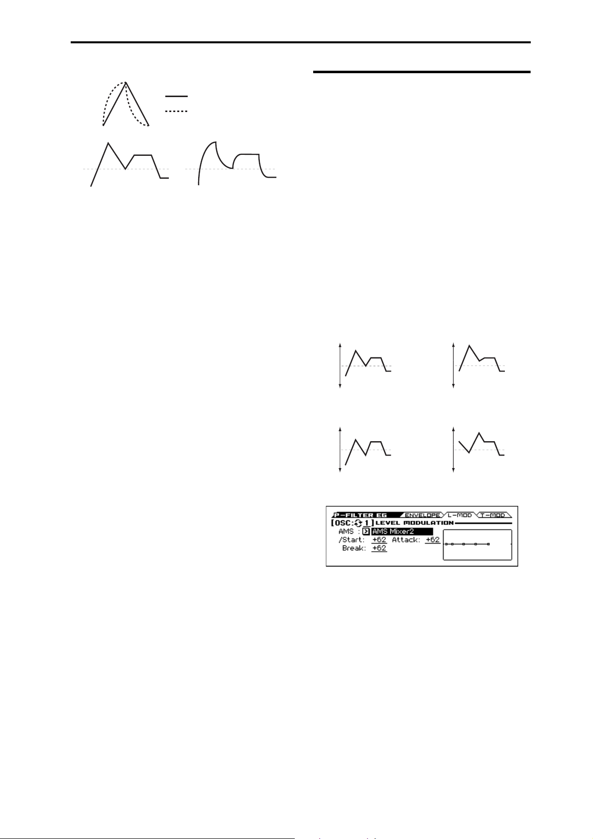
7: P–FILTER EG (Filter Envelope) 7–2: L-MOD (Level Modulation)
Curve=0L (Linear)
Curve=0L (Linear)
Curve=10E (Exp/Log)
Curve=10E (Exp/Log)
Original Shape
Positive AMS on Start and Break,
Negative AMS on Attack
Negative AMS on Start,
Attack, and Break
Positive AMS on Start,
Attack, and Break
Filter EG Curve
When you change the curvature, the EG times remain the same.
However, greater curvature will tend to sound faster, because the
value changes more quickly at the beginning.
Different curve settings for up and down
You may find that different amounts of curvature are suitable for
segments which go up and segments which go down.
For instance, a curve of 3 is a good default setting for upward
segments, such as Attack. On the other hand, a curve of 6 or more
is good for downward segments, such as Decay and Release.
Attack [0L (Linear), 1...9, 10E (Exp/Log)]
This sets the curvature of the Attack segment - the transition from
the Start level to the Attack level.
7–2: L-MOD (Level Modulation)
These settings let you use any AMS source to control the Level
parameters of the EG. The Start, Attack, and Break levels share a
single AMS source, but can each have different modulation
intensities.
By using different settings for each of the three levels, you can
cause both subtle and dramatic changes to the EG shape, as shown
below.
Once the EG has started a segment between two points, that
segment can no longer be modulated. This includes both the time
of the segment, and the level reached at the end of the segment.
For instance, if the EG is in the middle of the Decay time, you can
no longer modulate either the Decay time or the Break level.
As another example, let’s say that you’ve assigned the Common
LFO to modulate the Break Level. The LFO may be moving all the
time, but the Break Level is only affected by the LFO’s value at
the instant that the Decay segment starts. After that, the level is
fixed.
Finally, this also means that modulating the Start level, Attack
level, or Attack time will not affect notes that are already
sounding, unless the EG is then reset via AMS.
Filter EG Level Modulation
Dcy/Brk (Decay) [0L (Linear), 1...9, 10E (Exp/Log)]
This sets the curvature of the Decay segment - the transition from
the Attack level to the Break level.
Slp/Sus (Slope) [0L (Linear), 1...9, 10E (Exp/Log)]
This sets the curvature of the Slope segment - the transition from
the Break level to the Sustain level.
Release [0L (Linear), 1...9, 10E (Exp/Log)]
This sets the curvature of the Release segment - the transition from
the Sustain level to the Release level.
Level
Each of the five levels can be either positive or negative.
Positive levels will make the cutoff frequency (or other AMS
destination) go up from its programmed value; negative levels will
make it go down.
Start [–99...+99]
This sets the initial EG level at note-on.
Attack [–99...+99]
This sets the level at the end of the Attack time.
Dcy/Brk (Break) [–99...+99]
Break, short for Break Point, sets the level at the end of the Decay
time.
Slp/Sus (Sustain) [–99...+99]
This sets the level at the end of the Slope time. Once it reaches the
Sustain level, the EG will stay there until note-off, unless it is reset
via AMS.
Release [–99...+99]
This sets the level at the end of the Release time.
EG Display
This shows the shape of the EG that's specified by the P–FILTER
EG settings. The location of the selected parameter is shown.
OSC (Oscillator Select) [1, 2]
Select the oscillator (1 or 2) that you want to edit.
Note: Oscillator 2 can be selected if Oscillator Mode is set to
Double.
AMS [List of AMS Sources]
Selects an AMS source to control the EG’s Level parameters.
For a list of AMS sources, please see “AMS (Alternate
Modulation Source) List” on page 282.
Start [–99...+99]
This controls the depth and direction of the AMS modulation for
the Start level.
For example, if you set the AMS source to Velocity and set St
(Start) to +99, the Start level will increase as you play harder. If
you instead set St (Start) to –99, the Start level will decrease as
you play harder.
Attack [–99...+99]
This controls the depth and direction of the AMS modulation for
the Attack level.
29
Page 38

Program mode
Break [–99...+99]
This controls the depth and direction of the AMS modulation for
the Break level.
EG Display
This shows the shape of the EG that's specified by the P–FILTER
EG settings. The location of the selected parameter is also shown.
7–3: T-MOD (Time Modulation)
These settings let you use three different AMS sources to control
the Time parameters of the EG. For each of the three AMS sources,
the Attack, Decay, Slope, and Release times each have their own
modulation intensities.
Filter EG Time Modulation
AMS=Velocity, Intensity = a positive (+) value
Note-on Note-on Note-on
“Attack”=+, “Decay”=+,
“Slope”=+, “Release”=+
Softly played note.
Original Shape
“Attack”=+, “Decay”=+,
“Slope”=+, “Release”=+
Stongly played note.
Times are longer.
Reaches Sustain more
slowly.
“Attack”=–, “Decay”=–,
“Slope”=–, “Release”=–
Stongly played note.
Times are shorter.
Reaches Sustain more
quickly.
OSC (Oscillator Select) [1, 2]
Select the oscillator (1 or 2) that you want to edit.
Note: Oscillator 2 can be selected if Oscillator Mode is set to
Double.
AMS1
AMS1 [List of AMS Sources]
Selects the first AMS source to control the EG’s Time parameters.
Velocity and Keyboard Track can both be useful here for instance.
For a list of AMS sources, please see “AMS (Alternate
Modulation Source) List” on page 282.
Attack [–99...+99]
This controls the depth and direction of the AMS modulation for
the Attack time.
For example, if you set the AMS source to Velocity and set At
(Attack) to +99, the Attack time will get much longer at higher
velocities. If you instead set At (Attack) to –99, the Attack time
will get much shorter at higher velocities.
When the AMS source is at its maximum value for instance, when
Ve lo ci ty is at 127 a setting of +8 will make the Attack time almost
twice as long, and a setting of –8 will cut the Attack time almost in
half. (see page 284)
30
Decay [–99...+99]
This controls the depth and direction of the AMS modulation for
the Decay time.
Slope [–99...+99]
This controls the depth and direction of the AMS modulation for
the Slope time.
Release [–99...+99]
This controls the depth and direction of the AMS modulation for
the Release time.
AMS2 and AMS3
These select the second and third AMS sources, respectively, for
controlling the EG’s Time parameters. Each has its own intensities
Page 39

7: P–FILTER EG (Filter Envelope) 7–3: T-MOD (Time Modulation)
for Attack, Decay, Slope, and Release. The parameters of both
AMS2 and AMS3 are identical to those of AMS1, above.
EG Display
This shows the shape of the EG that's specified by the P–FILTER
EG settings. The location of the selected parameter is also shown.
V
7–1...3: FUNCTION
•0: Write Program, Write/Initialize Program see page 63
•1: Solo Setting see page 63
•2: Compare see page 64
•3: Auto Song Setup see page 64
•4: Add to Favorite see page 64
•5: Copy Oscillator see page 64
•6: Swap Oscillator see page 64
•7: Sync Both EGs see page 65 (only ENVELOPE page)
For more information, please see the “Program: Function” section
on page 63.
31
Page 40

Program mode
AMS Intensity
8: P–Amp
Oscillators 1 and 2 have separate controls for volume (also called
“amplitude,” or “amp” for short), pan, dedicated amp envelopes
and keyboard tracking generators.
These pages let you control all of these related parameters. Among
other things, you can:
• Set the pan position and pan modulation.
• Control amp level and modulation, including keyboard tracking,
the amp envelope, LFO modulation, and AMS control.
Note that when the Oscillator Mode is set to Single, only
Oscillator 1’s amp and pan parameters are active; the pages for
Oscillator 2 will be grayed out.
8–1: BASIC
This page controls the basic settings for the Amp section. Here you
can:
• Set the initial volume level.
• Control the pan position and pan modulation.
Note: Random cannot be selected via a MIDI control change.
You'll need to select it here.
AMS (Pan) [List of AMS Sources]
This selects an AMS source to modulate Pan.
For a list of AMS sources, please see “AMS (Alternate
Modulation Source) List” on page 282.
AMS Intensity [–99...+99]
This controls the depth and direction of the AMS modulation for
Pan settings.
For example, if Pan is set to C064 and AMS is set to Note
Number, positive (+) intensities will cause the sound to move
toward the right as you play higher than C4, and toward the left as
you play lower than C4. Negative (–) intensities will have the
opposite effect.
DKIT-SET (Use DKit Setting) [Off, On]
This option is available only when the Oscillator Mode is set to
Drums.
Unlike standard Programs, Drum Kits can have a different pan
setting for every note. This parameter lets you choose whether to
use the Drum Kit pan settings, or to use the Program’s pan setting
instead.
On (checked): The Program will use the Drum Kit’s per-note pan
settings; pan AMS will still apply (see page 172). This is the
default setting.
Off (unchecked): The Program will ignore the Drum Kit’s
settings, and use the Program pan instead.
All keys of the drum kit will use the Pan setting.
OSC (Oscillator Select) [1, 2]
Select the oscillator (1 or 2) that you want to edit.
Note: Oscillator 2 can be selected if Oscillator Mode is set to
Double.
Amp Level [000...127]
This controls the basic volume level of Oscillator 1, before
keyboard tracking, velocity, and other modulation.
Mixer, DrumTrack and volume
You can control the Oscillator volume directly from the sliders in
the 0–3 Mixer page. This is a separate parameter, in addition to
Amp Level.
MIDI and volume
You can control the Program’s overall volume via MIDI
using both Volume (CC#7) and Expression (CC#11). When
used one at a time, the two controllers work in exactly the
same way: a MIDI value of 127 is equal to the Amp Level
setting, and lower values reduce the volume.
If both CC#7 and CC#11 are used simultaneously, the one
with the lower value determines the maximum volume, and
the one with the higher value scales down from that
maximum. This is controlled on the global MIDI channel (see
page 159).
Pan [Random, L001...C064...R127]
This controls the stereo pan of Oscillator 1. A setting of L001
places the sound at the far left, C064 in the center, and R127 to the
far right.
When this is set to Random, the pan position will be different for
each note-on.
You can also control pan via MIDI Pan (CC#10).
A CC#10 value of 0 or 1 places the sound at the far left, 64
places the sound at the location specified by the Pan
parameter, and 127 places the sound at the far right. This is
controlled on the global MIDI channel (see page 159).
32
Page 41

8–2: MOD (Amp Modulation)
AMS Intensity
Low velocity
High velocity
Time
Volume
Time
This page contains the settings for Oscillators 1 and 2’s Amp level
modulation. Among other things, you can:
• Assign AMS modulation for the Amp level.
• Control the effect of the LFOs on the Amp level.
You can modulate the Amp level by both velocity and an AMS
source.
This modulation scales the basic Amp level and Amp EG level
parameters. The resulting volume is determined by multiplying the
volume changes of the amp EG by other values such as AMS. If
these original levels are low, the maximum volume available with
modulation will also be reduced.
8: P–Amp 8–2: MOD (Amp Modulation)
AMS (LFO1) [List of AMS Sources]
This selects an AMS modulation source to scale the amount of the
LFO1 that’s applied to the Amp level.
For a list of AMS sources, please see “AMS (Alternate
Modulation Source) List” on page 282.
AMS Intensity [–99...+99]
This controls the depth and direction of the LFO1 AMS
modulation for the Amp level.
LFO2
The parameters for LFO2 are identical to those for LFO1. For
more information, please see the descriptions under LFO1, above.
OSC (Oscillator Select) [1, 2]
Select the oscillator (1 or 2) that you want to edit.
Note: Oscillator 2 can be selected if Oscillator Mode is set to
Double.
Velocity to EG
Velocity Intensity [–99...+99]
With positive (+) values, the volume will increase as you play
harder.
With negative (–) values, the volume will decrease as you play
harder.
Velocity modulation of the Amp level, with Amp EG
Modulation
AMS [List of AMS Sources]
This selects any AMS modulation source to control the Amp1
level. For a list of AMS sources, please see “AMS (Alternate
Modulation Source) List” on page 282.
AMS Intensity [–99...+99]
This controls the depth and direction of the modulation.
For example, if AMS is set to M.Wheel:#01, positive (+) values
of this parameter will make the volume increase when you move
the modulation wheel away from yourself.
Note that if the other modulation settings have already raised the
volume to its maximum level (double the Amp Level and Amp
EG level settings), the volume cannot be increased any further.
LFO1
Intensity (LFO1) [–99...+99]
This controls the depth and direction of LFO1’s effect on the
oscillator’s volume.
Negative (–) values will invert the LFO waveform.
33
Page 42

Program mode
Low Break
Bottom-
Low
Low-
Center
Center-
High
HighTop
Center High Break
–99 –97 –95 –48 –25
+99 +50 +25
High Break: C4Low Break: D1 Center: G2
Change to
Ramp values:
Ramp values:
Amp Keyboard Tracking
Louder x2
Silence
No change
Volume
8–3: KEYTRK (Keyboard Track)
Keyboard tracking lets you vary the volume as you play up and
down the keyboard. Usually, some amount of key tracking is
necessary in order to make the volume consistent across the entire
range.
KROSS’s keyboard tracking can be fairly complex, if desired. You
can create different rates of change over up to four different parts
of the keyboard. For instance, you can:
• Make the volume increase very quickly over the middle of the
keyboard, and then increase more slowly or not at all in the
higher octaves.
• Make the volume increase as you play lower on the keyboard.
• Create abrupt changes at certain keys, for split-like effects.
For more information, please see the “How it works: Keys and
Ramps” section on page 26.
OSC (Oscillator Select) [1, 2]
Select the oscillator (1 or 2) that you want to edit.
Note: Oscillator 2 can be selected if Oscillator Mode is set to
Double.
Key
Low Break [C–1...G9]
This specifies the note that will be the break point connecting the
two sloped lines in the low region.
Center [C–1...G9]
This specifies the note that will be the break point in the center of
keyboard tracking. At this key, the keyboard tracking has no effect
on the volume, or on any AMS destinations.
High Break [C–1...G9]
This specifies the note that will be the break point connecting the
two sloped lines in the high region.
Note: Tip: You can also set the note value by the keyboard (see
page 12 of the Operation Guide).
Ramp
Positive ramp values mean that the keyboard tracking output
increases as you play farther from the Center Key; negative ramp
values mean that it decreases.
Because of this, the meanings of positive and negative ramp
settings will change depending on whether the ramp is to the left
or right of the Center Key.
Bottom-Low and Low-Center: negative ramps make the
keyboard tracking’s output go down as you play lower, and
positive ramps make the output go higher.
Center-High and High-Top: negative ramps make the keyboard
tracking’s output go down as you play higher, and positive ramps
make the output go up.
Differences from other Keyboard Tracks
There are several differences between the Amp keyboard tracking
and the Filter and Common keyboard tracking.
For example, the results of the Ramp values are different. As
shown in the graphic “Amp Keyboard Tracking,” below, negative
slopes are more steep than positive slopes.
Also, the amp does not have separate control of Intensity. Instead,
Intensity is always fixed at the maximum amount, allowing
keyboard tracking to change the volume from complete silence to
twice as loud as the programmed level.
Bottom-Low [–Inf, –99...+99, +Inf]
This sets the slope between the bottom of the MIDI note range and
the Key Low key. For normal key track, use negative values.
Low-Center [–Inf, –99...+99, +Inf]
This sets the slope between the Key Low and Center keys. For
normal key track, use negative values.
Center-High [–Inf, –99...+99, +Inf]
This sets the slope between the Center and Key High keys. For
normal key track, use positive values.
34
Page 43

High-Top [–Inf, –99...+99, +Inf]
This sets the slope between the Key High key and the top of the
MIDI note range. For normal key track, use positive values.
Ramp Change in level
–Inf Silent in one half-step
–99 Silent in one whole-step
–95 Silent in one octave
–48 Silent in two octaves
–25 Silent in four octaves
00 no change
+25 x2 in four octaves
+50 x2 in two octaves
+99 x2 in one octave
+Inf x2 in one half-step
+Inf and –Inf ramps
+Inf and –Inf are special settings which create abrupt changes for
split-like effects. When a ramp is set to +Inf or
–Inf, the keyboard tracking will go to its extreme highest or lowest
value over the span of a single key.
When a ramp is set to +Inf, the keyboard tracking will go to its
highest value (double the programmed volume) over a single halfstep.
Similarly, when a ramp is set to –Inf, the keyboard tracking will go
to its lowest value (complete silence) over a single half-step.
Note: If you set the Cent Hi (Center-High) ramp to +Inf or
–Inf, the Hi Top (High-Top) parameter will be grayed out.
Similarly, if you set the Lo Cent (Low-Center) ramp to +Inf or –
Inf, the Btm Lo (Bottom-Low) ramp will be grayed out.
8: P–Amp 8–3: KEYTRK (Keyboard Track)
Amp KTrk is also an AMS source
You can use the keyboard tracking as an AMS source to modulate
other parameters, just like the envelopes and LFOs. Simply select
Amp KTrk in the AMS list for the desired parameter.
V
8–1...3: FUNCTION
•0: Write Program, Write/Initialize Program see page 63
•1: Solo Setting see page 63
•2: Compare see page 64
•3: Auto Song Setup see page 64
•4: Add to Favorite see page 64
•5: Copy Oscillator see page 64
•6: Swap Oscillator see page 64
For more information, please see the “Program: Function” section
on page 63.
35
Page 44

Program mode
Threshold
9: P–AMP EG (Amp Envelope)
9–1: ENVELOPE
These parameters let you create time-varying changes in the
volume of oscillators.
OSC (Oscillator Select) [1, 2]
Select the oscillator (1 or 2) that you want to edit.
Note: Oscillator 2 can be selected if Oscillator Mode is set to
Double.
Reset AMS [List of AMS Sources]
This selects an AMS source to reset the EG to the start point. For
instance, you can use a tempo-synced LFO to trigger the EG in a
repeating rhythm. This reset is in addition to the initial note-on,
which always causes the EG to start.
For a list of AMS sources, please see “AMS (Alternate
Modulation Source) List” on page 282.
Note: Once the Amp EG is in its Release segment, it cannot be
reset. (Otherwise, the sound might keep playing forever!)
Threshold [–99...+99]
This sets the AMS level which will trigger the EG reset.
Among other things, you can use this to adjust the exact point in an
LFO’s phase where the EG will be reset, effectively controlling its
“groove” against other rhythmic effects. When the threshold is
positive, the EG triggers when passing through the threshold
moving upwards. When the threshold is negative, the EG triggers
when passing through the threshold moving downwards.
Note: With some LFO shapes, and with faster LFO speeds, the
LFO may not always reach the extreme values of +99 or –99. In
this case, setting the Threshold to these values may cause
inconsistent behavior, or may mean that the EG doesn’t reset at all.
If this happens, reduce the Threshold until the EG triggers
consistently.
TIME/CURVE/LEVEL
These parameters specify how the amp 1 EG will change over
time.
Amp EG
Volume
Attack
Start
Level
Level
Time
Attack
Decay
Time
Note-on or reset Note-o
Break
Level
Time
Slope
Time
Sustain
Level
Release
Time
Level
Start [00...99]
This sets the initial volume level at note-on.
Attack [00...99]
This sets the level at the end of the Attack time.
Dcy/Brk (Break) [00...99]
Break, short for the Break Point, sets the level at the end of the
Decay time.
Slp/Sus (Sustain) [00...99]
This sets the level at the end of the Slope time. Once it reaches the
Sustain level, the EG will stay there until note-off (unless it is reset
via AMS).
Time
Higher values mean longer times, as shown below.
EG Value Actual Time
10 10 ms
20 44 ms
30 104 ms
40 224 ms
50 464 ms
60 944 ms
70 1.8 seconds
80 3.8 seconds
90 10.9 seconds
99 87.3 seconds
Attack [00...99]
This sets how long the EG takes to move from the Start level to the
Attack level.
For the fastest possible attack time, you can set the Start level to
+99; in this case, the EG will start instantaneously at its maximum
value.
36
Dcy/Brk (Decay) [00...99]
This sets the time it takes to move from the Attack level to the
Break level.
Slp/Sus (Slope) [00...99]
This sets how long the EG takes to move from the Break level to
the Sustain level. Once it reaches the Sustain level, the EG will
stay there until note-off (unless it is reset via AMS).
Release [00...99]
This sets how long it takes the EG to move from the Sustain level
to silence.
Page 45

Curve
Curve=0L (Linear)
Curve=0L (Linear)
Curve=10E (Exp/Log)
Curve=10E (Exp/Log)
Original Shape
Positive AMS on Start and Break,
Negative AMS on Attack
Negative AMS on Start,
Attack, and Break
Volume
Time
Volume
Time
Volume
Time
Volume
Time
Positive AMS on Start,
Attack, and Break
For the sake of simplicity, most of the diagrams in this manual
show envelopes as being made out of straight lines. In actuality,
though, envelopes are more likely to be made out of curves.
In other words, each segment’s level will change quickly at first,
and then slow down as it approaches the next point. This tends to
sound better than straight, linear segments.
Classic analog synth envelopes made these curved shapes
naturally. The KROSS goes a step further than vintage synths,
however, and lets you control the amount of curvature separately
for each of the four envelope segments.
When you change the curvature, the EG times remain the same.
However, greater curvature will tend to sound faster, because the
value changes more quickly at the beginning.
Amp EG Curve
Different curve settings for up and down
You may find that different amounts of curvature are suitable for
segments which go up and segments which go down.
For instance, a curve of 3 is a good default setting for upward
segments, such as Attack. On the other hand, a curve of 6 or more
is good for downward segments, such as Decay and Release.
9: P–AMP EG (Amp Envelope) 9–2: L-MOD (Level Modulation)
9–2: L-MOD (Level Modulation)
These settings let you use any AMS source to control the Level
parameters of the EG. The Start, Attack, and Break levels share a
single AMS source, but can each have different modulation
intensities.
By using different settings for each of the three levels, you can
cause both subtle and dramatic changes to the EG shape, as shown
below.
Once the EG has started a segment between two points, that
segment can no longer be modulated. This includes both the time
of the segment, and the level reached at the end of the segment.
For instance, if the EG is in the middle of the Decay time, you can
no longer modulate either the Decay time or the Break level.
As another example, let’s say that you’ve assigned the Common
LFO to modulate Break Level. The LFO may be moving all the
time, but the Break Level is only affected by the LFO’s value at
the instant that the Decay segment starts. After that, the level is
fixed.
Finally, this also means that modulating the Start level, Attack
level, or Attack time will not affect notes that are already
sounding, unless the EG is then reset via AMS.
Amp EG Level Modulation
Attack [0L (Linear), 1...9, 10E (Exp/Log)]
This sets the curvature of the Attack segment - the transition from
the Start level to the Attack level.
Dcy/Brk (Decay) [0L (Linear), 1...9, 10E (Exp/Log)]
This sets the curvature of the Decay segment - the transition from
the Attack level to the Break level.
Slp/Sus (Slope) [0L (Linear), 1...9, 10E (Exp/Log)]
This sets the curvature of the Slope segment - the transition from
the Break level to the Sustain level.
Release [0L (Linear), 1...9, 10E (Exp/Log)]
This sets the curvature of the Release segment - the transition from
the Sustain level to the Release level.
EG Display
This shows the shape of the EG that's specified by the P–AMP EG
settings. The location of the selected parameter is shown.
OSC (Oscillator Select) [1, 2]
Select the oscillator (1 or 2) that you want to edit.
Note: Oscillator 2 can be selected if Oscillator Mode is set to
Double.
AMS Intensity
AMS [List of AMS Sources]
This selects an AMS source to control the EG’s Level parameters.
For a list of AMS sources, please see “AMS (Alternate
Modulation Source) List” on page 282.
Start [–99...+99]
This controls the depth and direction of the AMS modulation for
the Start level.
For example, if you set the AMS source to Velocity and set St
(Start) to +99, the Start level will increase as you play harder. If
you instead set St (Start) to –99, the Start level will decrease as
you play harder.
Attack [–99...+99]
This controls the depth and direction of the AMS modulation for
the Attack level.
37
Page 46
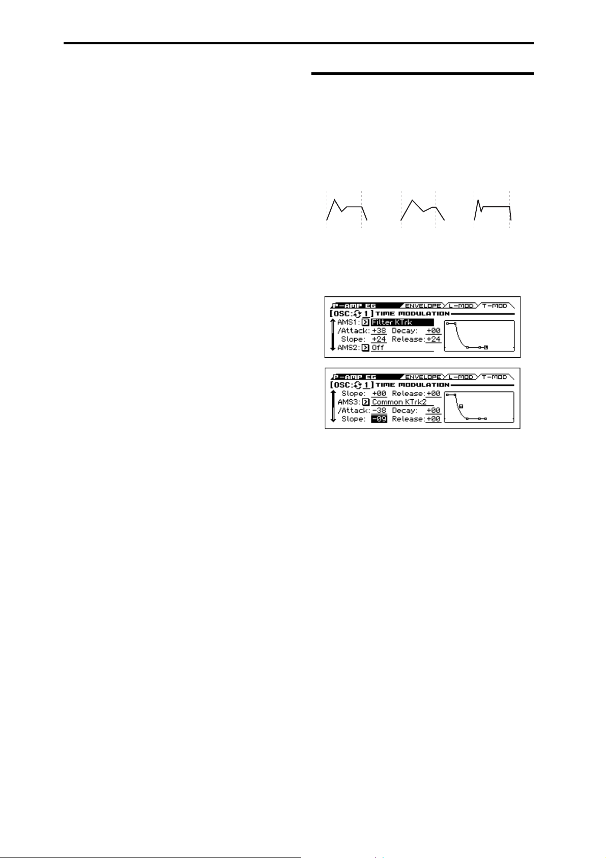
Program mode
Note-on Note-o Note-on Note-o Note-on Note-o
AMS=Velocity, Intensity = a positive (+) value
“Attack”= +, “Decay”= +,
“Slope”= +, “Release”= +
Softly played note.
Original Shape.
“Attack”= +, “Decay”= +,
“Slope”= +, “Release”= +
Strongly played note.
Times are longer.
Reaches Sustain
more slowly.
“Attack”=–, “Decay”=–,
“Slope”=–, “Release”=–
Strongly played note.
Times are shorter.
Reaches Sustain more
quickly.
Break [–99...+99]
This controls the depth and direction of the AMS modulation for
the Break level.
EG Display
This shows the shape of the EG that's specified by the P–AMP EG
settings. The location of the selected parameter is shown.
9–3: T-MOD (Time Modulation)
These settings let you use three different AMS sources to control
the Time parameters of the EG. For each of the three AMS sources,
the Attack, Decay, Slope, and Release times each have their own
modulation intensities.
Amp EG Time Modulation
OSC (Oscillator Select) [1, 2]
Select the oscillator (1 or 2) that you want to edit.
Note: Oscillator 2 can be selected if Oscillator Mode is set to
Double.
AMS1 Intensity
AMS1 [List of AMS Sources]
Selects the first AMS source to control the EG’s Time parameters.
Velocity and Keyboard Track can both be useful here for instance.
For a list of AMS sources, please see “AMS (Alternate
Modulation Source) List” on page 282.
Attack [–99...+99]
This controls the depth and direction of the AMS modulation for
the Attack time.
For example, if you set the AMS source to Velocity and set At
(Attack) to +99, the Attack time will get much longer at higher
velocities. If you instead set At (Attack) to –99, the Attack time
will get much shorter at higher velocities.
When the AMS source is at its maximum value for instance, when
Ve lo ci ty is at 127, a setting of +8 will make the segment time
almost twice as long and a setting of –8 will cut the segment time
almost in half.
Decay [–99...+99]
This controls the depth and direction of the AMS modulation for
the Decay time.
Slope [–99...+99]
This controls the depth and direction of the AMS modulation for
the Slope time.
38
Page 47

10: P–OSC LFO 10–1: 1.WAV (LFO1 Waveform)
Square
Sine
Saw
Triangle Step Triangle-4
Step Saw-6
Step Saw-4
Step Triangle-6
Exponential
Saw Down
Exponential
Triangle
Guitar
Exponential
Saw Up
Random1
(S/H)
Random2
(S/H)
Random3
(S/H)
Random4
(Continuous)
Random6
(Continuous)
Random5
(Continuous)
LFO waveform
Release [–99...+99]
This controls the depth and direction of the AMS modulation for
the Release time.
AMS2 Intensity and AMS3 Intensity
These select the second and third AMS sources, respectively, for
controlling the EG’s Time parameters. Each has its own intensities
for Attack, Decay, Slope, and Release. The parameters of both
AMS2 and AMS3 are identical to those of AMS1, above.
EG Display
This shows the shape of the EG that's specified by the P–AMP EG
settings. The location of the selected parameter is shown.
V
9–1...3: FUNCTION
•0: Write Program, Write/Initialize Program see page 63
•1: Solo Setting see page 63
•2: Compare see page 64
•3: Auto Song Setup see page 64
•4: Add to Favorite see page 64
•5: Copy Oscillator see page 64
•6: Swap Oscillator see page 64
•7: Sync Both EGs see page 65 (only ENVELOPE pege)
For more information, please see the “Program: Function” section
on page 63.
10: P–OSC LFO
Each of the Oscillators has two LFOs, which you can use to
modulate the filter, amp, pitch, and many other parameters.
The two Oscillators also share a single Common LFO, similar to
the global LFO on some vintage analog synths.
These pages let you set up all of the parameters for all five LFOs.
In the P–OSC LFO page you can adjust settings for the four LFOs
of the oscillator; in the P–CMN LFO/KT page you can adjust
settings for the common LFO.
10–1: 1.WAV (LFO1 Waveform)
AMS Intensity
This page has all of the controls for the first LFO of Oscillator 1.
For instance, you can:
• Select the LFO’s basic waveform, and modify it with the Shape
parameter.
• Control the LFO’s frequency, and assign AMS controllers to
modulate the frequency.
•Use the Key Sync parameter to choose whether the LFO runs
separately for each voice, or is synchronized across all of the
voices
•Use the Fade and Delay parameters to control how long the
LFO waits to start after note-on, and whether it starts abruptly
or fades in slowly.
• Set the LFO to sync to MIDI tempo.
OSC (Oscillator Select) [1, 2]
Select the oscillator (1 or 2) that you want to edit.
Note: Oscillator 2 can be selected if Oscillator Mode is set to
Double.
LFO1 (LFO1 )Waveform [Triangle...Random6 (Cont)]
This selects the basic LFO waveform, as shown in the graphic
below.
Most of the waveforms should be self-explanatory, but a few will
benefit from more details:
Guitar is intended for guitar vibrato, and its shape is specifically
tuned for this purpose. The waveform is positive-only, so that
when used for pitch, it will only bend up, and not down.
Random1 (S/H) generates traditional sample and hold
waveforms, where the level changes randomly at fixed intervals of
time.
Random2 (S/H) randomizes both the levels and the timing.
39
Page 48

Program mode
Pitch
ShapeWavef orm
FadeDelay
Note-on
Random3 (S/H) generates a pulse wave with random timing. It’s
the opposite of traditional sample and hold; the timing varies, but
the levels don’t.
Random4–6 (Cont=Continuous) are smoothed versions of
Random 1–3, with ramps instead of steps. You can use them to
create more gentle random variations.
Phase (Start Phase) [–180...+180, Random]
This controls the phase of the waveform at the start of the note, in
steps of 5 degrees.
If Key Sync is Off, the Start Phase will apply only to the first note
of the phrase.
Offset [–99...+99]
By default, almost all of the LFO waveforms are centered around
0, and then swing all the way from –99 to +99. This parameter lets
you shift the LFO up and down, so that for instance it’s centered
on 50, and then swings from –49 to +149.
For example, let’s say that you’re using an LFO for vibrato. If the
Offset is 0, the vibrato will be centered on the note’s original
pitch, bending it both up and down.
If the Offset is +99, on the other hand, the vibrato will only raise
the pitch above the original note.
Offset settings and pitch change produced by vibrato
Note: Shape does not affect the Square and Random3 waveforms,
since their values are always either +99 or –99. When these are
selected, Shape is grayed out.
AMS (Shape) [List of AMS Sources]
This selects an AMS source for controlling the LFO’s Shape.
Modulating the shape can dramatically alter the effect of the LFO
try it out!
For a list of AMS sources, please see “AMS (Alternate
Modulation Source) List” on page 282.
AMS Intensity [–99...+99]
This controls the depth and direction of the AMS (Shape)
modulation.
Start
Key Sync. [Off, On]
On (checked): When Key Sync is On, the LFO starts each time
you press a key, and an independent LFO runs for each note. This
is the normal setting.
Off (unchecked): When Key Sync is Off, the LFO starts from the
phase determined by the first note in the phrase, so that the LFOs
for all notes being held are synchronized together. The Fade and
Delay settings will only apply to the first note’s LFO.
Note that even if Key Sync is Off, each note’s LFO speed may still
be different if you modulate the Frequency by note number,
velocity, key scaling, or other note-specific AMS sources.
The one exception to this is the Guitar waveform, which is
designed to emulate bending a string on a guitar so that the pitch
only goes up, and not down. Because of this, the waveform is
centered on 50, and not on 0. Of course, you can always use a
negative Offset to shift it back down below 0 again!
Since the Offset affects the output values of the LFO, it’s
important to note that it affects the signal after the Shape function,
as shown below:
How the LFO signal is affected by Shape and Offset
Shape [–99...+99]
Shape adds curvature to the basic waveform. As you can see in the
graphic below, this can make the waveforms either more rounded
or more extreme. It can also be useful to emphasize certain value
ranges, and de-emphasize others.
For example, let’s say that you are using a triangle LFO to
modulate filter cutoff. If Shape emphasizes the high value range,
the filter will spend more time at the higher frequencies. If it
emphasizes the low range, the filter will spend more time at the
lower frequencies.
Fade [00...99]
The LFO can fade in gradually, instead of simply starting
immediately at full strength. This parameter specifies the time
from when the LFO begins to play until it reaches its maximum
amplitude.
If the Delay parameter is being used, then the fade will begin after
the delay is complete.
When Key Sync is Off, the fade will apply only to the first note in
the phrase.
LFO Fade and Delay
Delay [00...99]
This sets the time from note-on until the LFO starts.
When Key Sync is Off, the delay applies only to the first note of
the phrase.
40
LFO Shape
+99
0
–99
Shape = 0 (original waveform)
Shape = +99
Shape = –99
Page 49

10–2: 1. FRQ (LFO1 Frequency)
OSC (Oscillator Select) [1, 2]
Select the oscillator (1 or 2) that you want to edit.
Note: Oscillator 2 can be selected if Oscillator Mode is set to
Double.
LFO1
Motion [Nomal, Stop]
Specifies how the LFO will operate.
Normal: Normal operation. The LFO will operate according to the
Frequency and other settings.
Stop: Instead of the LFO operating normally, it will ignore the
Frequency setting. The LFO will maintain the initial value
(determined by the combination of Waveform, Phase, Shape, and
Offset) until the note-off.
Since the value will change only at note-on, using a Random
waveform will produce a fixed value that changes randomly at
each note-on (or at the first note-on).
Frequency Type [Manual, MIDI/Tempo Sync.]
Manual: The Frequency and Frequency Modulation settings
will determine the speed of the LFO, and the tempo settings will
have no effect.
MIDI/Tempo Sync: The LFO will synchronize to the system
tempo, as set by either the TEMPO knob or MIDI Clock. The LFO
speed will be controlled by the Base Note and Times parameters,
below. All settings for Frequency and Frequency Modulation
will be ignored.
Frequency Type: Manual
Frequency [00...99]
This controls the speed of the LFO, before any modulation. Higher
values mean faster speeds, as shown in the table below.
By using AMS modulation, you can also get speeds much faster
and much slower than what are available through this basic setting.
Frequency Value Freque ncy in Hz
00 0.014 Hz
10 0.112 Hz
20 0.422 Hz
30 0.979 Hz
40 1.79 Hz
50 2.84 Hz
60 4.14 Hz
70 5.69 Hz
80 7.49 Hz
90 9.53 Hz
99 26.25 Hz
99 + Fine 99 32 Hz
10: P–OSC LFO 10–2: 1. FRQ (LFO1 Frequency)
AMS Intensity [–99...+99]
This sets the initial amount of AMS1 (Frequency). The Int Mod
AMS then adds to this initial amount.
When AMS is at its maximum value (for example by moving the
modulation wheel fully away from yourself), the AMS affects the
frequency as shown below:
Intensity Change to LFO Frequency
+99 64x
+82 32x
+66 16x
+49 8x
+33 4x
+16 2x
–16 1/2x
–33 1/4x
–49 1/8x
–66 1/16x
–82 1/32x
–99 1/64x
Fast er
Slower
IntModAMS (Intensity Mod AMS) [List of AMS Sources]
This selects a secondary AMS source to scale the intensity of
AMS1.
For a list of AMS sources, please see “AMS (Alternate
Modulation Source) List” on page 282.
AMS Intensity [–99...+99]
This controls the depth and direction of the IntModAMS. Even if
the main AMS1 Intensity is set to 0, IntModAMS can still control
the final amount of AMS A over the full +/–99 range.
For example, if AMS1 is set to the Pitch EG, and IntModAMS is
set to M.Wheel: #01, positive settings mean that the intensity of
the Pitch EG modulation of LFO Frequency will increase by
moving the modulation wheel fully away from yourself.
AMS2 (Freq. AMS2) [List of AMS Sources]
This selects the second AMS source for the LFO1’s frequency. For
a list of AMS sources, please see “AMS (Alternate Modulation
Source) List” on page 282.
AMS Intensity [–99...+99]
This controls the amount of modulation from AMS2 (Freq.
AMS2).
Frequency Type: MIDI/Tempo Sync.
If you've set the Frequency Type to MIDI/Tempo Sync, use the
Base Note and Times parameters to specify a tempo-synchronized
LFO speed.
Base Note (Sync. Base Note) [ ... ]
This sets the basic speed of the LFO, relative to the system tempo.
The values range from a 32nd note to a whole note, including
triplets.
Times (Sync. Times) [x1...x32]
This multiplies the length of the Base Note. For instance, if the
Base Note is set to a sixteenth note, and Times is set to 03, the
LFO will cycle over a dotted eighth note.
AMS1 (Frequency) [List of AMS Sources]
This selects the first AMS source for the LFO1’s frequency. For a
list of AMS sources, please see “AMS (Alternate Modulation
Source) List” on page 282.
Note that you can use LFO2 to modulate LFO1’s frequency.
41
Page 50
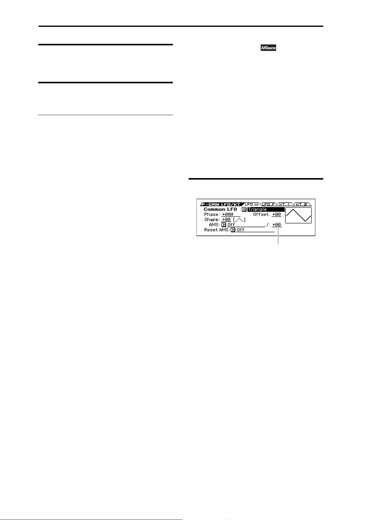
Program mode
AMS Intensity
10–3: 2. WAV (LFO2 Waveform)
see “10–1: 1.WAV (LFO1 Waveform)” on page 39
10–4: 2. FREQ (LFO2 Frequency)
“10–2: 1. FRQ (LFO1 Frequency)” on page 41
V
10–1...4: FUNCTION
•0: Write Program, Write/Initialize Program see page 63
•1: Solo Setting see page 63
•2: Compare see page 64
•3: Auto Song Setup see page 64
•4: Add to Favorite see page 64
•5: Swap LFO 1&2 see page 65
For more information, please see the “Program: Function” section
on page 63.
11: P–CMN LFO/KT
This is a single, Common LFO, global for all voices in the
Program like the modulation LFOs in some vintage analog synths.
Differences from LFO1/2
The Common LFO starts running as soon as you select the
Program, and only resets when you tell it to do so explicitly via the
Reset Source control, below. This is different from LFO1/2’s Key
Sync parameter, which resets whenever all notes are released.
The Common LFO’s persistence can be handy if you want to
create a constant rhythm with an LFO, and then play “underneath”
that rhythm without re-triggering it. For instance, you can use a
MIDI controller in your sequencer to reset the Common LFO
every few bars, regardless of what notes are being played.
The Common LFO has most of the same controls as LFO1/2.
However, it does not include the Delay, Fade, and Key Sync
settings, since these only make sense for per-voice LFOs.
11–1: LFO.W (Common LFO Waveform)
Common LFO (Common LFO Waveform)
[Triangle...Random6 (Cont)]
This selects the basic LFO waveform. For a complete list of the
waveforms and more details, please see the entry under LFO1
“LFO1 (LFO1 )Waveform” on page 39.
Phase [–180...+180, Random]
The Reset AMS, described above, lets you reset the Common
LFO. This is the phase from which the LFO will start when it is
reset.
Offset [–99...+99]
By default, almost all of the LFO waveforms are centered around
0, and then swing all the way from –99 to +99. This parameter lets
you shift the LFO up and down, so that for instance it’s centered
on 50, and then swings from –49 to +149.
For a complete description, please see the entry under LFO1
“Offset” on page 40.
Shape [–99...+99]
Shape adds curvature to the basic waveform. For more details,
please see the entry under LFO1 “Shape” on page 40.
Note: Shape does not affect the Square and Random3 waveforms,
since their values are always either +99 or –99.
AMS (Shape) [List of AMS Sources]
This selects an AMS source for controlling the LFO’s Shape.
Modulating the shape can dramatically alter the effect of the LFO,
try it out!
For a list of AMS sources, please see “AMS (Alternate
Modulation Source) List” on page 282.
42
AMS Intensity [–99...+99]
This controls the depth and direction of the AMS (Shape)
modulation.
Page 51

Reset AMS [List of AMS Sources]
This selects an AMS source to reset the LFO to the Start Phase.
The LFO resets when the AMS value passes the halfway mark:
+50 for most AMS sources, or 64 for MIDI controllers.
To create an effect similar to the per-voice LFO’s Key Sync.
setting, set this to Gate 2+ Damper.
11: P–CMN LFO/KT 11–2: LFO.F (Common LFO Frequency)
11–2: LFO.F (Common LFO Frequency)
AMS Intensity
Motion [Nomal, Stop]
Specifies how the Common LFO will function.
Normal: Normal operation. The LFO will function according to
the Frequency and other settings.
Stop: Instead of the LFO operating normally, it will ignore the
Frequency setting. The LFO will maintain the initial value
(determined by the combination of Waveform, Phase, Shape, and
Offset) until the note-off.
Since the value will change only at note-on, using a Random
waveform will produce a fixed value that changes randomly at
each note-on (or at the first note-on).
Frequency Type [Manual, MIDI/Tempo Sync.]
Manual: The Frequency and Frequency Modulation settings
will determine the speed of the LFO, and the tempo settings will
have no effect.
MIDI/Tempo Sync: The LFO will synchronize to the system
tempo, as set by either the Tempo knob or MIDI Clock. The LFO
speed will be controlled by the Base Note and Times parameters,
below. All settings for Frequency and Frequency Modulation
will be ignored.
Frequency Type: Manual
Frequency [00...99]
AMS1 (Frequency) [List of AMS Sources]
AMS Intensity [–99...+99]
IntModAMS (Intensity Mod AMS) [List of AMS Sources]
AMS Intensity [–99...+99]
AMS2 (Freq. AMS2) [List of AMS Sources]
AMS Intensity [–99...+99]
The parameters for the Frequency type: Manual are identical to
those for LFO1 “Freqency Type:; Manual.”
For more information, please see page 41
Frequency Type: MIDI/Tempo Sync.
Base Note (Sync. Base Note) [
... ]
Times (Sync. Times) [x1...x32]
The parameters for the Frequency type: MIDI/Tempo Sync. are
identical to those for LFO1 “Freqency Type:; MIDI/Tempo Sync.”
For more information, please see page 41
43
Page 52

Program mode
Low Break
Bottom-
Low
Low-
Center
Center-
High
HighTop
Center High Break
Ramp = –Inf
Ramp = +Inf
Ramp = –50
Key Low Center Key High
11–3: KT.1(Common Keyboard Track 1)
The two Oscillators share two Common keyboard tracking
generators, in addition to each Oscillator’s dedicated keyboard
tracking for the Filter and Amp. You can use these Common
keytracks as AMS sources for modulating most AMS destinations.
The Common Keyboard Track parameters are shared by the entire
Program, but the actual AMS values are calculated individually for
each voice.
What does Keyboard Tracking do?
At its most basic, keyboard tracking lets you vary the modulation
amount as you play up and down the keyboard. This can be useful
for making the timbre consistent across the entire range, or
adjusting parameters according to pitch.
The KROSS keyboard tracking can be fairly complex, if desired.
You can create different rates of change over up to four different
parts of the keyboard. For instance, you can:
• Make the modulation increase very quickly over the middle of
the keyboard, and then increase more slowly or not at all in the
higher octaves.
• Make the modulation increase as you play lower on the
keyboard.
• Create abrupt changes at certain keys, for split-like effects.
Common Keyboard Tracking
At the Center Key, the AMS value is always 0.
AMS
+99
Ramp:
+99
0
–99
–99
AMS
For more information, please see the “6–5: KTRK (Keyboard
Track)” section on page 26.
Ramp = –50
Low Break Center High Break
Ramp = +99
Ramp:
+99
+50
00
–50
–99
High Break [C–1...G9]
This specifies the note that will be the break point connecting the
two sloped lines in the high region.
Tip: You can also set the note value by the keyboard (see page 12
of the Operation Guide).
Ramp
Positive ramp values mean that the keyboard tracking output
increases as you play farther from the Center Key; negative ramp
values mean that it decreases.
Because of this, the meanings of positive and negative Ramp
settings will change depending on whether the ramp is to the left
or right of the Center Key.
Bottom-Low and Low-Center: negative ramps make the
keyboard tracking’s output go down as you play lower on the
keyboard, and positive ramps make the output go higher.
Center-High and High-Top: negative ramps make the keyboard
tracking’s output go down as you play higher on the keyboard, and
positive ramps make the output go up.
Bottom-Low [–Inf, –99...+99, +Inf]
This sets the slope between the bottom of the MIDI note range and
the Low Break key. For normal key track, use negative values.
Low-Center [–Inf, –99...+99, +Inf]
This sets the slope between the Low Break and Center keys. For
normal key track, use negative values.
Center-High [–Inf, –99...+99, +Inf]
This sets the slope between the Center and High Break keys. For
normal key track, use positive values.
High-Top [–Inf, –99...+99, +Inf]
This sets the slope between the High Break key and the top of the
MIDI note range. For normal key track, use positive values.
The table below shows how the Ramps affect the AMS output:
Ramp value AMS change
–Inf goes to –99 in 1 half-step
–99 –20 per octave
–50 –10 per octave
0no change
+50 +10 per octave
+99 +20 per octave
+Inf goes to +99 in 1 half-step
Key
Low Break [C–1...G9]
This specifies the note that will be the break point connecting the
two sloped lines in the low region.
Center [C–1...G9]
This specifies the note that will be the break point in the center of
keyboard tracking. At this key, the keyboard tracking has no effect
on the AMS destinations.
44
+Inf and –Inf ramps
+Inf and –Inf are special settings which create abrupt changes for
split-like effects. When a ramp is set to +Inf or
–Inf, the keyboard tracking will go to its extreme highest or lowest
value over the span of a single key.
+Inf and –Inf Ramps
Note: If you set the Center-High ramp to +Inf or –Inf, the High-
To p parameter will be grayed out. Similarly, if you set the Low-
Page 53

12: P–AMS MIXER 11–4: KT.2 (Common Keyboard Track 2)
Center ramp to +Inf or –Inf, the Bottom-Low ramp will be grayed
out.
11–4: KT.2
Here you can adjust settings for the second common keyboard
track.
For more information, please see the “11–3: KT.1(Common
Keyboard Track 1)” section on page 44.
V
11–1...4: FUNCTION
•0: Write Program, Write/Initialize Program see page 63
•1: Solo Setting see page 63
•2: Compare see page 64
•3: Auto Song Setup see page 64
•4: Add to Favorite see page 64
For more information, please see the “Program: Function” section
on page 63.
(Common Keyboard Track 2)
12: P–AMS MIXER
Each Oscillator has two AMS Mixers, which are simple but
powerful tools for combining and modifying AMS signals.
The two Oscillators also share two Common keyboard tracking
generators, in addition to the dedicated keyboard tracking for the
Filter and Amp.
These pages let you control all of these modulation sources.
Note that when the Oscillator Mode is set to Single, only
Oscillator 1’s AMS Mixers are active; the pages for Oscillator 2
will be grayed out.
12–1: 1 (AMS Mixer1)
The AMS Mixers combine two AMS sources into one, or process
an AMS source to make it into something new.
For instance, they can add two AMS sources together, or use one
AMS source to scale the amount of another. You can also use them
to change the shapes of LFOs and EGs in various ways, modify the
response of realtime controllers, and more.
You can select the output of the AMS mixers as an AMS source in
the same way as an LFO.
This also means that the original, unmodified inputs to the AMS
Mixers are still available as well. For instance, if you use LFO1 as
an input to an AMS Mixer, you can use the processed version of
the LFO to control one AMS destination, and the original version
to control another.
Finally, you can cascade the two AMS Mixers together, by using
AMS Mixer 1 as an input to AMS Mixer 2.
OSC (Oscillator Select) [1, 2]
Select the oscillator (1 or 2) that you want to edit.
Note: Oscillator 2 can be selected if Oscillator Mode is set to
Double.
Type (Mixer Type) [A+B, Amt AxB, Offset, Smoothing, Shape,
Quantize, Gate Control]
This controls the type of processing performed by AMS Mixer 1.
Each of the Mixer Types is discussed in detail over the next several
pages.
A+B adds two AMS sources together. For more information,
please see the “A+B” section on page 46.
Amt Ax B scales the amount of one AMS source with the other.
For more information, please see the “Amt AxB” section on
page 46.
Offset adds or subtracts a constant value to or from an AMS
source. For more information, please see the “Offset” section on
page 47.
Smoothing specifies the smoothness of movement between two
values. You can use this to smooth sudden changes such as an
abrupt movement of the modulation wheel or sharp angle of the
LFO. For more information, please see the “Smoothing” section
on page 47.
Shape adds curvature to the AMS input. For more information,
please see the “Shape” section on page 47.
Quantize turns smooth transitions into discrete steps. For more
information, please see the “Quantize” section on page 48.
45
Page 54

Program mode
AMS A
AMS B
Amt A
Amt B
Output
Gate Control uses a third AMS source to switch between two
AMS inputs (or a fixed value). For more information, please see
the “Gate Control” section on page 49.
PROPERTIES
A+B
AMS Mixer, Type = A+B
A+B merges two AMS sources into one. This can be handy when
you need to add one more modulation source to a parameter, but
you’ve already used up all of the available AMS slots.
For instance, let’s say that you’re using an LFO to modulate Filter
Resonance, and then you decide that it would be interesting to
scale that parameter with an EG as well. Resonance has only a
single AMS input, but you can easily merge the LFO and the EG
together using the A+B AMS Mixer:
1. Assign the LFO to AMS A.
2. Assign the EG to AMS B.
3. Assign the AMS Mixer as the Filter Resonance AMS
source.
AMS Mixer A+B example
AMS A: LFO
Amt AxB
AMS Mixer, Type =Amt A x B
AMS A
AMS B
Amt B
This Mixer Type uses AMS B to scale the amount of AMS A. For
instance, you can control the amount of LFO1 with the Filter EG,
or control the amount of the Pitch EG with the modulation wheel.
AMS Mixer Amt AxB example
AMS A: LFO
AMS B: EG
Amt A*B Output
Amt A
AMS A [List of AMS Sources]
This selects the first AMS source, which can then be scaled by
AMS B.
For a list of AMS sources, please see “AMS (Alternate
Modulation Source) List” on page 282.
Output
AMS B: EG
A+B Output
AMS A [List of AMS Sources]
This selects the first AMS input.
For a list of AMS sources, please see “AMS (Alternate
Modulation Source) List” on page 282.
AMS A Amount [–99...+99]
This controls the depth and direction of the AMS A input.
AMS B [List of AMS Sources]
This selects the second AMS input.
For a list of AMS sources, please see “AMS (Alternate
Modulation Source) List” on page 282.
AMS B Amount [–99...+99]
This controls the depth and direction of the AMS B input.
AMS A Amount [–99...+99]
This controls the initial amount of AMS A, before modulation
from AMS B. Input from AMS B then adds to this initial amount.
Even if Amount A is set to 0, AMS B can still control the final
amount of AMS A over the full +/–99 range.
AMS B [List of AMS Sources]
This selects the second AMS source, to scale the amount of AMS
A.
For a list of AMS sources, please see “AMS (Alternate
Modulation Source) List” on page 282.
AMS B Amount [–99...+99]
This controls the depth and direction of the AMS B modulation of
AMS A.
For example, if AMS A is set to LFO1 and AMS B is set to the
Filter EG, positive settings mean that the EG will increase the
amount of LFO1.
Tip: use SW 1/2 to turn an AMS source on and off
You can use Amt AxB to “gate” an AMS source:
1. Set AMS A to the desired source, and set the AMS A
Amount to 0.
2. Set AMS B to SW1 or 2, and AMS B Amount to +99.
Now, SW1 or 2 will turn AMS A on and off.
46
Page 55

12: P–AMS MIXER 12–1: 1 (AMS Mixer1)
AMS A
Amt A
Output
Original AMS A: Smoothing with Long Attack
and Short Decay:
Smoothing with Short Attack & Long Decay:
Offset
AMS Mixer, Type = Offset
This simple processor adds a constant offset to the input, and also
allows you to double the gain of an AMS source.
For instance, you can use this to convert a bipolar LFO (both
negative and positive) to a unipolar LFO (positive only). To do
this:
1. Select the LFO as the AMS A input.
2. Set the AMS A Amount to 50.
This cuts the overall level of the LFO in half, so that instead of
swinging between –99 and +99, it only swings between
–50 and +50.
3. Set the AMS A Offset to 50.
This adds 50 to the LFO level, so that it now swings between 0 and
+99, as shown below.
AMS Mixer Offset examples
AMS A: LFO
+99
0
Smoothing
This Mixer Type smooths out the AMS input, creating more gentle
transitions between values. You have separate control of the
amount of smoothing during the attack (when the signal is
increasing) and decay (when it’s decreasing).
The higher the Attack and Decay settings, the more the input will
be smoothed.
Low settings provide subtle controller smoothing, creating more
gradual aftertouch, for instance. Higher settings create auto-fade
effects, transforming a quick gesture into a longer fade-in and/or
fade-out event.
Smoothing can also be used to alter the shape of programmable
mod sources, such as LFOs and EGs. For instance, you can turn a
“blip” into a simple envelope shape, as shown below.
AMS Mixer Smoothing examples
–99
Oset = +50, Amount = 50
+99
0
–99
Oset = –99, Amount = +199
+99
0
–99
Clipped
at Output
AMS A [List of AMS Sources]
This selects the AMS source to be offset.
For a list of AMS sources, please see “AMS (Alternate
Modulation Source) List” on page 282.
AMS A Amount [–199...+199]
This controls the basic level of AMS A.
+199 doubles the original signal level, while –199 doubles the
original signal level and inverts the phase. The values are clipped
only at the output; internally, they can be greater than the normal
range of –99 to +99.
AMS A Offset [–199...+199]
This controls the amount of offset for AMS A.
Setting Offset to +199 shifts an AMS input of –99 all the way to
+99. In conjunction with high AMS A Amount values, this can be
useful for creating clipped shapes, such as shown in the last of the
“AMS Mixer Offset examples” above.
AMS A [List of AMS Sources]
This selects the AMS source to be smoothed.
For a list of AMS sources, please see “AMS (Alternate
Modulation Source) List” on page 282.
AMS A Attack [00...+99]
This controls the attack time of the smoother, or how long it takes
the smoother to reach a new, higher value.
Higher Attack settings mean longer times.
Depending on how quickly the AMS input value is changing, high
Attack settings may mean that the value is never quite reached, as
shown in “AMS Mixer Shape examples” above.
AMS A Decay [00...+99]
This controls the decay time of the smoother, or how long it takes
the smoother to reach a new, lower value.
Higher Decay settings mean longer times.
Shape
This Mixer Type adds curvature to the AMS input. This applies
deformation to the AMS input. You can use this to customize a
controller curve, such as the exponential curve of the modulation
wheel or the logarithmic curve of velocity control. It can also alter
the shape of programmable modulation sources, such as EGs and
LFOs.
Note: Shape only affects AMS signals which already have some
amount of slope, such as EGs, triangle and sine LFOs, and so on. It
does not affect signals which only contain abrupt transitions, such
as square waves.
AMS A [List of AMS Sources]
This selects the AMS input source to be shaped.
For a list of AMS sources, please see “AMS (Alternate
Modulation Source) List” on page 282.
47
Page 56

Program mode
+99
0
–99
+99
0
–99
+99
0
–99
Symmetric
Asymmetric
Bipolar Triangle Wave
SymmetricAsymmetric
Bipolar Sawtooth Wave
Shape = 0 (original waveform)
Shape = +99
Shape = –99
+99
0
–99
Asymmetric
(not recommended)
Unipolar Triangle Wave
Symmetric
+99
0
–99
+99
0
–99
+99
0
–99
Unipolar (e.g., Bend(+)) Bipolar (e.g., LFO)
Original
AMS A
Quantize
Steps = 8
Quantize
Steps = 16
Shape [–99...+99]
This controls the amount of curvature, and whether the curves are
concave or convex. As you can see in the graphic examples, the
shape will tend to emphasize certain value ranges, and deemphasize others.
For example, let’s say that you are using a triangle LFO, through
Shape, to modulate filter cutoff. If Shape emphasizes the high
value range, the filter will spend more time at the higher
frequencies. If it emphasizes the low range, the filter will spend
more time at the lower frequencies.
Mode [Symmetric, Asymmetric]
This selects whether the Shape parameter will produce one or two
curves. The graphic “AMS Mixer Shape examples” may help to
visualize how this works.
Asymmetric will produce a single curve, extending from
–99 to +99.
Symmetric will produce two matching curves extending outwards
from 0 to –99 and +99, respectively.
Bipolar and Unipolar AMS sources
To understand Shape, it helps to understand the difference between
bipolar and unipolar AMS sources.
Bipolar sources can swing all the way from –99 to +99, with 0 in
the middle. Most LFOs are bipolar, for instance; so is Pitch Bend.
Generally, bipolar AMS sources will work better with the
Asymmetric mode, but Symmetric may also produce interesting
results.
Unipolar sources only go from 0 to 99, with 50 in the middle.
MIDI controllers, such as M.Wheel: #01, are all unipolar. In
practice, EGs are usually programmed to be unipolar, even though
the Filter and Pitch EGs do allow both positive and negative
levels.
With unipolar sources, it’s almost always better to use the
Symmetric mode. The Asymmetric mode can cause offsets and
other strange results.
AMS Mixer Shape examples
48
Quantize
This Mixer Type changes the input from a continuous signal into a
series of discrete steps. Instead of moving smoothly between
values, it will snap immediately from one value to another.
You can use this to change the shape of LFOs or EGs, or to force a
controller to land on a few specific values.
AMS Mixer Quantize examples
AMS A [List of AMS Sources]
This selects the AMS input source to be quantized.
Page 57

12: P–AMS MIXER 12–1: 1 (AMS Mixer1)
Control
Below
At & Above
Fixed Value
AMS
Fixed Value
AMS
For a list of AMS sources, please see “AMS (Alternate
Modulation Source) List” on page 282.
Number Of Steps [2...32]
This controls the severity of the effect. The lower the number of
steps, the more “steppy” the output will be.
For instance, when this is set to 2, there will be “steps” at 0, 50,
and 99. With a bipolar AMS input, there will also be steps at –50
and –99.
As another example, when it is set to 5, there will be steps at 0, 20,
40, 60, 80, and 99 (as well as –20, –40, –60, –80, and –99 for
bipolar inputs).
Tip: Quantized pitch bend wheel Pitch Bend
You can use the pitch bend wheel to create quantized pitch bends
that simulate sliding across the frets of a guitar, or jump-bend
sounds caused by differences in the length of the tube of a trumpet.
To do so:
1. Select the AMS Mixer as the Oscillator Pitch AMS input.
2. Set the Pitch AMS Intensity to any exact half-step value,
such as +5.00, +7.00, etc.
3. Set the Bend(+X), Bend(–X) amount to 0.00.
4. In the AMS Mixer, select the Pitch Bend as AMS A.
5. Set the Number Of Steps to the same number you used in
Step 2 .
Now, playing the pitch bend wheel will create quantized pitch
bends.
Gate Control
AMS Mixer, Type = Gate Control
Control At Note-On Only [Off, On]
When this is enabled (checked), the value of the Control Source
at note-on will select the output (Below Threshold or At & Above
Threshold). The selected output will then remain active
throughout the duration of the note, regardless of any subsequent
change in the Control Source’s value.
Note that the output value itself can continue to change; only the
selection of Below or At & Above is fixed.
Threshold [–99...+99]
This sets the value of the Control Source where the gate opens or
closes.
Gate Output
If the value of the Control Source is less than the Threshold, the
Gate outputs the preset value or AMS source selected under Below
Threshold.
If the value of the Control Source is greater than or equal to the
Threshold, the Gate outputs the preset value or AMS source
selected in the At & Above Threshold parameter.
Below Threshold [Fixed Value, AMS A]
This selects whether Below Threshold uses a preset value, or the
selected AMS source.
Fixed Value [–99...+99]
This lets you set a specific value to be used when the Control
Source is less than the Threshold. This only applies when Below
Threshold is set to Fixed Value.
AMS A [List of AMS Sources]
This lets you set an AMS source to pass through the Gate when the
Control Source is less than the Threshold. This only applies
when Below Threshold is set to AMS A.
This Mixer Type lets you set up two different AMS sources (or
fixed AMS amounts), and then switch between the two using a
third AMS source.
It’s similar to an audio gate with a side-chain, but with even more
flexibility since you get to choose what happens when the gate is
closed (below the threshold), as well as when it’s open (above the
threshold).
You can also choose whether the gate will be able to open and
close continuously in response to the control source, or whether it
only opens or closes at the beginning of the note, and then stays
that way over the note’s entire duration.
You can use the Gate to:
• Use a foot-switch (or other controller) to apply pitch-bend or
other effects to some notes, but not to others
• The parameter will be applied when the controller reaches a
specific threshold. For example, the velocity value could
control the filter resonance only if the velocity value exceeds
90.
• Use the modulation wheel, switches, or controllers to change
between two separate LFOs (or other AMS sources).
Gate Contro Source [List of AMS Sources]
This selects the AMS source to control the gate.
At & Above Thresh (At & Above Threshold)
[Fixed Value, AMS B]
This selects whether At & Above Threshold uses a preset value,
or the selected AMS source.
Fixed Value [–99...+99]
This lets you set a specific value to be used when the Control
Source is greater than or equal to the Threshold. This only applies
when At & Above Threshold is set to Fixed Value.
AMS B [List of AMS Sources]
This lets you set an AMS source to pass through the Gate when the
Control Source is greater than or equal to the Threshold. This
only applies when At & Above Threshold is set to AMS B.
Tips on using the Gate
Selective pitch-bend, using a switch
You can use Control At Note-On Only to apply an effect to some
notes, but not others, based on the state of an AMS source at the
start of the note. For instance:
1. Set the Control Source to Foot SW: CC#82
(Connect a foot switch, and set the G–INPUT/CTRL> FOOT page
Foot SW Assign parameter to Foot Switch (CC#82).)
2. Set Control At Note-On Only to On (checked).
3. Set the Threshold to 50.
4. Set Below Threshold to a Fixed Value of +00.
5. Set At & Above Threshold to AMS B: Pitch Bend
6. On the OSC Pitch page, assign the AMS Mixer to control
the pitch.
7. Turn off the foot switch, and while holding down a chord,
move the pitch bend wheel. The pitch will not change.
49
Page 58

Program mode
(If the pitch changes, go to the OSC Pitch page and set Pitch
Bend(+X) and Bend(–X) to +00.)
8. Turn on the foot switch, and add a new note to the previous
chord.
9. Move the pitch bend wheel; pitch bend will be applied only
to the newly-played note.
The new note will bend, but the original chord (played before you
pressed on the foot-switch) will not.
Selective pitch-bend, using only the pitch bend wheel
You can also use a single AMS source as both the Control Source
and a value source:
1. Set the Control Source to Pitch Bend.
2. Set Control At Note-On Only to On (checked).
3. Set the Threshold to 00.
4. Set Below Threshold to AMS A: Pitch Bend.
5. Set At & Above Threshold to a Fixed Value of 00.
6. On the OSC Pitch page, assign the AMS Mixer to control
the pitch.
7. With the pitch bend wheel in the center, play a chord, and
hold it through step 9.
8. Turn the pitch bend wheel toward yourself, and add a new
note to the previous chord.
(If the pitch changes, go to the OSC Pitch page and set Pitch
Bend(+X) and Bend(–X) to +00.)
9. Use the pitch bend wheel to bend the pitch of the new note.
This method is particularly good for bending the top note of a
chord up to pitch.
12–2: 2 (AMS Mixer2)
This is the second AMS Mixer for Oscillators. The parameters are
exactly the same as those for AMS Mixer 1, as described under
“12–1: 1 (AMS Mixer1)” on page 45.
V
12–1, 2: FUNCTION
•0: Write Program, Write/Initialize Program see page 63
•1: Solo Setting see page 63
•2: Compare see page 64
•3: Auto Song Setup see page 64
•4: Add to Favorite see page 64
•5: Copy Oscillator see page 64
•6: Swap Oscillator see page 64
For more information, please see the “Program: Function” section
on page 63.
Generating a static value
Sometimes, it can be handy to have a preset value as an AMS
source. The Gate is one way to create this. To do so:
1. Set both Below Threshold and At & Above Threshold to
Fixed Value, and enter the same value into each.
Now, the AMS mixer will always generate this static value.
50
Page 59

13: P–ARP (Arpeggiator) 13–1: SETUP
UP
DOWN
RANDOM
13: P–ARP (Arpeggiator)
Here you can adjust settings for the arpeggiator used by the
program.
You can adjust settings so that when you select a program, these
arpeggiator settings will automatically switch to the arpeggiator
settings that are memorized in the selected program.
(Global>SYSTEM page “Load ARP when changing Program” on
page 157)
The arpeggiator can be switched on/off by the ARP button. When
on, the button’s LED will light up.
The ARP button on/off status and the tempo can also be saved for
each individual program.
Note: The parameters below that are marked with “*” can also be
edited in “PROG> ARP”
These settings will be valid when “Load ARP when
changing” Program (Global>SYSTEM page) is checked.
You can control the arpeggiator from an external sequencer,
or record note data generated by the arpeggiator onto an
external sequencer. (see page 76 of the Operation Guide)
Note: Pattern, Resolution, Octave, Sort, Latch, Key Sync.,
Keyboard, and (Tempo) can also be set from the PROG> ARP
page.
Preset: ALT1
ALT1
Preset: ALT2
ALT2
Preset: RANDOM
Octave* [1, 2, 3, 4]
Specifies the number of octaves where the arpeggio will be played.
If a user arpeggio pattern is selected, the range of the
arpeggio will depend on the Octave Motion (page 169)
setting.
13–1: SETUP
Pattern* [Preset: UP...RANDOM, 0000...1027]
Selects the arpeggio pattern.
Preset/User No Contents
Preset: UP...RAMDOM Preset arpeggio patterns
0000...0915 Preloaded arpeggio patterns
0916...1027 User arpeggio patterns
Note: 0000–1027 are rewritable. Use Global ARP PATTERN to
create arpeggio patterns.
Example: Preset pattern
The way that the pattern is played will depend on settings such as
Octave and Sort. The preset in the following diagrams show how
the arpeggio will be played when Octave is set to 1, and Sort is
checked. Preset: RANDOM is only one possibility.
Preset: UP
Preset: DOWN
Octave: 4
UP
Resolution* [ , , , , , , , ]
Specifies the timing resolution of the arpeggio. The notes of the
arpeggio will be played at the interval you specify: , , , ,
, , , or . The speed of the arpeggio pattern is determined
by the Arpeggiator (Tempo) and the Resolution.
Gate [000...100(%), Step]
Specifies the length (gate time) of each note in the arpeggio.
000–100(%): Each note will be played with the specified gate
time.
Step: This is available when a user arpeggio pattern 0000–1027 is
selected for Pattern. When this is selected, the gate time specified
for each step will be used.
You can also use MOD [GATE] to control this. When the value is
+00, the gate length will be as specified here.
Velocity [001...127, Key, Step]
Specifies the velocity of the notes in the arpeggio.
001–127: Each note will sound with the specified velocity value.
Key: Each note will sound with the velocity value where it was
actually played.
Step: This is available when a user arpeggio pattern between
0000–1027 is selected for Pattern. When this is selected, the
velocity specified for each step will be used.
You can also use MOD [VELOCITY] to control this. When the
value is +00, the velocity value will be as specified here.
When a preload user arpeggio pattern is selected, setting the Gate
or Ve lo ci ty to Step will add a sense of groove to the arpeggio
pattern.
51
Page 60
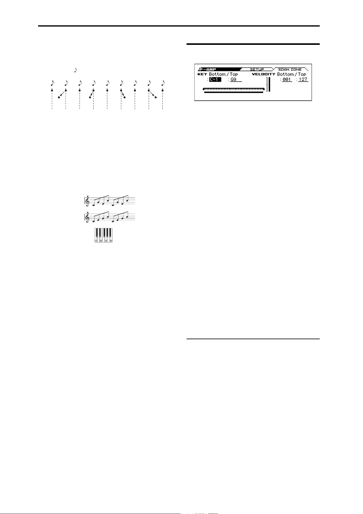
Program mode
Step
123456789
Swing
–50 –25 +25 +50
When Resolution = , Step Per Beat = x1
Swing [–100...+100(%)]
This adjusts the timing for the step numbers that are specified by
Steps per Beat for Swing.
You can also use PROG> ARP page MOD [SWING] to control
this.
Note: Swing has no effect on the preset patterns.
Sort* [Off, On]
This specifies the order that the notes you press will be
arpeggiated.
On (checked): Notes will be arpeggiated in the order of their
pitch, regardless of the order that you pressed them.
Off (unchecked): Notes will be arpeggiated in the order that you
pressed them.
Sort
OFF, UP
Sort
ON, UP
13–2: SCAN ZONE
KEY
This shows the Scan Zone setting.
Bottom (Bottom Key) [C–1…G9]
Top (Top Key) [C–1…G9]
These parameters specify the range of notes (keys) where the
arpeggiator will function. Top K e y is the upper limit, and Bottom
Key is the lower limit.
The arpeggiator will operate when you play keys within the
specified range. Keys outside of this range can be played in the
normal manner, and will not be affected by the arpeggiator.
For example if you set Pattern to Preset:, check Latch, set Top
Key to B3, and Bottom Key to C-1, playing a note B3 or lower
will trigger the arpeggiator. Since Latch is on, the arpeggio will
continue even after you release the keys. You can use the C4 and
higher keys to play conventionally along with the arpeggio
sounded by the B3 and lower keys. To change the arpeggio, play
keys in the range of B3 and below.
Latch* [Off, On]
Specifies whether or not the arpeggio will continue playing after
you take your hand off of the keyboard.
On (checked): The arpeggio will continue playing after you
remove your hand from the keyboard.
Off (unchecked): The arpeggio will stop when you remove your
hand from the keyboard.
Key Sync.* [Off, On]
Specifies whether the arpeggio pattern will begin when you press a
key, or whether it will always follow the (Tempo) (PROG>
MAIN).
On (checked): The arpeggio pattern will start playing from the
beginning when a note-on occurs from a condition where no keys
are pressed. This setting is suitable when you are playing in
realtime and want the arpeggio to play from the beginning of the
measure.
Off (unchecked): The arpeggio pattern will always play according
to the (Tempo).
Keyboard* [Off, On]
This specifies whether the notes you play on the keyboard will be
sounded as usual in addition to being sounded as part of the
arpeggio.
On (checked): The notes you play will be sounded on their own,
in addition to being sounded as part of the arpeggio. For example
if you simultaneously press two or more notes, they will be
sounded as usual in addition to being played as arpeggiated notes.
Off (unchecked): Only the arpeggiated notes will be heard.
Note: You can use the FUNCTION Copy Arpeggiator to copy
arpeggiator settings from another program or combination (see
page 65).
VELOCITY
Bottom (Bottom Velocity) [001…127]
Top (Top Velocity) [001…127]
Specifies the range of velocities where the arpeggiator will
function. Top Ve l o c i t y is the upper limit, and Bottom Velocity is
the lower limit.
The arpeggiator will operate when you play notes with a velocity
(playing strength) that is within the specified range. Notes played
with a velocity outside this range will be sounded normally,
without regard to the arpeggiator.
Note: You can also set the note value and velocity value bythe
keyboard (see page 12 of the Operation Guide).
V
13–1, 2: FUNCTION
•0: Write Program, Write/Initialize Program see page 63
•1: Solo Setting see page 63
•2: Compare see page 64
•3: Auto Song Setup see page 64
•4: Add to Favorite see page 64
•5: Copy Arpeggiator see page 65
For more information, please see the “Program: Function” section
on page 63.
52
Page 61

14: P–DRUM TRACK 14–1: PATTERN
Bottom
Pattern
Top
14: P–DRUM TRACK
Here you can adjust settings for the Drum Track used by the
program.
14–1: PATTERN
Here you can select a drum track pattern and specify how it will
sound.
In Program mode, the drum track patterns are triggered on the
Global MIDI channel. The MIDI transmit channel is
specified by the DrumTrack Prog MIDI Ch (G– MIDI>
OUT). Use the DrumTrack Prog MIDI Out (G– MIDI>
OUT) setting to specify whether the pattern will transmit
MIDI note data. The default setting is channel 10.
The drum track program will not transmit or receive MIDI
program changes.
Off: The pattern will stop when you take your hand off the
keyboard (i.e., when all notes are off).
On: The pattern will continue playing until the DRUM TRACK
button is turned off (LED unlit), regardless of whether you are
performing via the keyboard or via MIDI.
KEY
Bottom (Keyboard Bottom) [C–1...G9]
Top (Keyboard Top) [C–1...G9]
This is valid if Trigger Mode is set to Wait KBD Trig.
It specifies the range of keys that will start the drum pattern.
VEL (Velocity)
Bottom (Velocity Bottom) [001...127]
Top (Velocity Top) [001...127]
This is valid if Trigger Mode is set to Wait KBD Trig.
It specifies the range of velocities that will start the drum pattern.
Note: You can also set the note value and velocity value by the
keyboard (see page 12 of the Operation Guide).
Pattern [000, 001...700]
This selects the drum pattern.
Preset/User No. Cont ents
000 Off
001...700 Preset drum patterns
Shift [–24...+00...+24]
This transposes the drum pattern in semitone steps. This means
that the instruments of the drum kit will change.
Tip: If you've selected a GM drum program for the Drum Track,
you should set this to -12.
Trigger Mode [Start Immediately, Wait KBD Trigger]
Start Immediately: When you press the DRUM TRACK button
to turn it on (LED lit), the drum track pattern will start according
to the Sync setting. When you turn it on, the drum track pattern
will stop.
Wait KBD Trig: When you press the DRUM TRACK button to
turn it on (LED lit), the drum pattern will wait to start. When you
play the keyboard, or when a MIDI note-on is received, the drum
pattern will start according to the Sync setting.
If you’ve selected Start Immediately, the DRUM TRACK
button will always be saved in the OFF state.
Sync [Off, On]
Off: The drum pattern will not synchronize to the currentlyrunning arpeggiator or step sequencer, but will start immediately.
On: The drum pattern will synchronize to the currently-running
arpeggiator or step sequencer.
Note: If you want the drum pattern to synchronize to the
arpeggiator, set the P–ARP> SETUP page Arpeggiator Setup Key
Sync parameter.
Latch [Off, On]
This specifies whether the drum track will continue playing even
after you take your hand off the keyboard.
This setting is available if Trigger Mode is set to Wait KBD Trig.
53
Page 62

Program mode
14–2: PROGRAM
DRUM/SFX (Program Select) [DRUM /SFX, Category Programs]
Here you can select the drum program that will be used by the
drum track.
Note: Only programs of the DRUM/SFX category can be selected.
If data is loaded or a system exclusive message is received so
that the selected program is no longer a Drum category
program, it will be replaced with the program of the Drum
category.
The drum track program will not transmit or receive MIDI
program changes.
Play/Mute [Play, Mute]
This mutes the drum track program. The setting will alternate each
time you press the Play/Mute button.
Play: The drum track program will be heard (Play).
Mute: The drum track program will not be heard (Mute).
Volume [000...127]
This adjusts the volume of the drum track program.
Note: You can use the 0–3: MIXER page to edit the Play/Mute,
Solo On/Off, and Vo lu me settings of the drum track. (see “0–3:
MIXER (Play Mixer)” on page 4)
Detune [–1200...+1200]
This adjusts the pitch in one-cent steps. One cent is 1/100th of a
semitone.
The pitch of each drum kit is specified in Global DRUM KIT.
FX Ctrl Bus (FX Control Bus) [Off, FC1, FC2]
This sends the output of the drum track program to the FX Control
bus (two mono channels FX Ctrl1, 2).
The FX Control bus is used when you want to use another audio
signal to control the input of an effect. You can use the two FX
Control buses (two mono channels) to freely control the effects in
a variety of ways. For more information, please see the “FX
Control Bus” section on page 199.
Bus Select [Dkit, L/R, IFX1...5, Off ]
This specifies the bus that will output the drum track program.
Dkit: The Bus Select, FX Control Bus, MFX Send1, and MFX
Send 2 settings (Global DRUM KIT> VOICE page) for each key
of the drum kit used by the selected drum track program will be
valid. Choose this setting if you want to apply separate insert
effects to each drum instrument.
Note: When making Dkit settings, you will normally use Dkit IFX
Patch to specify the output destination.
L/R: Output to the L/R bus.
IFX1, 2, 3, 4, 5: Output to the IFX1–5 bus.
Off: The sound will not be output to the L/R bus, or IFX1–5 bus.
Use the Off setting if you have connected the drum track program
output in series to a master effect. Use Send1 (to MFX1) or Send2
(to MFX2) to adjust the send level.
1 (MFX Send 1) [000...127]
2 (MFX Send 2) [000...127]
These specify the send level where the output of the drum track
program will be sent to each master effect.
Send 1: Send the signal to master effect 1.
Send 2: Send the signal to master effect 2.
If Bus Select is set to IFX1–5, the send levels to the master effects
are set by the post-IFX1–5 Send1 and Send2 (P–FX ROUTING>
MIXER).
You can use CC#93 to control MFX Send 1, and CC#91 to
control MFX Send 2.
DKit IFX Patch
IFX1 [L/R, IFX1...5, Off]
IFX2 [L/R, IFX1...5, Off]
IFX3 [L/R, IFX1...5, Off]
IFX4 [L/R, IFX1...5, Off]
IFX5 [L/R, IFX1...5, Off]
Here you can patch the Bus Select setting specified for each key of
the drum kit, temporarily changing its connection destination from
the originally specified insert effect to some other destination. This
can be executed only if the drum track program’s Bus Select is set
to DKit and the Bus Select (Global DRUM KIT> VOICE page)
for each key of the drum kit is set to IFX1–5.
As the patch destination, choose an insert effect or L/R, IFX1–5,
or Off as the output bus.
Note: If you want to return the drum kit to its previous state,
change these settings to IFX1IFX1, IFX2IFX2, IFX3IFX3,
IFX4IFX4, and IFX5IFX5.
The preload kits typically assign snare sounds to IFX1, kick
sounds to IFX2, cymbal sounds to IFX3, and toms, percussion,
and other sounds to IFX4. In such cases if you set Bus Select to
Dkit, these sounds will be sent to IFX1, IFX2, IFX3 and IFX4, but
IFX1 and IFX2 are set for normal (non-drum) programs. In such
cases, you can use Dkit IFX Patch to route these drum sounds to
unused IFX; for example, you might send the snare sounds to
IFX3, kick sounds to IFX4, and other sounds to IFX5. For more
information, please see the “Effect Guide” section on page 197.
V
14–1, 2: FUNCTION
•0: Write Program, Write/Initialize Program see page 63
•1: Solo Setting see page 63
•2: Compare see page 64
•3: Auto Song Setup see page 64
•4: Add to Favorite see page 64
•5: Copy Drum Track see page 64
For more information, please see the “Program: Function” section
on page 63.
54
Page 63

15: P–STEP SEQ (Step Sequencer) 15–1: BASIC
Resolution = , Swing = +16
Step
123456789
Swing
Resolution = , Swing = +16
Resolution = , Swing = +16
When Step/Bt = X1
+16
+16 +16 +16
10 11 12 13 14 15 16
+16 +16 +16 +16
Step
123456789
Swing
When Step/Bt = X2
+16 +16
10 11 12 13 14 15 16
+16 +16
Step
123456789
Swing
When Step/Bt = X4
+16
10 11 12 13 14 15 16
+16
15: P–STEP SEQ (Step Sequencer)
Here you can adjust settings for the step sequencer that are used by
the program.
15–1: BASIC
Program [000...040]
Here you can select the drum program that will be used by the step
sequencer.
Note: Only drum programs can be selected.
If the specified number is no longer a drum program because
PCG data was loaded or SysEX data was received, it will be
replaced by the first drum program.
The step sequencer program will not transmit or receive
MIDI program changes.
(Tempo) [40.00... 300.00, EXT]
See “ (Tempo)” on page 2.
x2: Swing will be applied to steps 3, 7, 11, 15 ... For example if
you set Resolution to and enter an 8-beat rhythm, the swing
effect will be applied to the 8-beat.
x4: Swing will be applied to steps 5, 13, 21, 29 ... For example if
you set Resolution to and enter an 8-beat rhythm, the swing
effect will be applied to the 8-beat.
(See illustration on the next page)
Step Sequencer Preview
This shows a graphic of the step sequencer pattern.
Resolution [ , , , , , , , ]
Specifies the timing resolution of the step sequencer. The notes of
the pattern will be played at the interval you specify: , , , ,
, , , or . The speed of the step sequuencer is determined
by the (Tempo) and the Resolution.
Lgth (Length) [01...64]
Specifies the number of steps to play; in other words, the length of
the pattern. Playback will repeat in the range of these steps.
Step/Bt (Steps per Beat for Swing) [x1, x2, x4]
Specifies the steps where the swing effect will be applied. The
amount of the swing effect is specified by the P–STEP SEQ>
MOD page Swing parameter.
x1: Swing will be applied to the even-numbered steps 2, 4, 6, 8 ...
55
Page 64

Program mode
y
front panel 1--16 buttons to turn steps on/o
When you turn RUN on, the indication will move
to the left, showing the currently-playing step.
15–2: EDIT
STEP SEQ - SETUP button
This page appears when you press the front panel STEP SEQ
SETUP button.
The step on/off status of front panel buttons 1–16 is linked with the
indication in this page.
STEP */* [1...64/01...64]
This shows the position and Length of the step that's selected in
this page.
ACCENT [Off, On]
Specifies an accent for the step. (see “To add an accent to a step”
on page 82 of the Operation Guide)
ZONE [A, B, C, D]
The currently-shown zone is indicated by [ ].
This is linked with the lit status of the front panel A/B/C/D LEDs.
A/B/C/D indicate the following ranges of steps.
A: Steps 1-16
B: Steps 17-32
C: Steps 33-48
D: Steps 49-64
STATUS [STOP, RUN]
Indicates whether the step sequencer is stopped (STOP) or running
(RUN).
TONE 01 (Kick/Note No.) [Step Off, On]
TONE 02 (Snr 1/Note No.) [Step Off, On]
TONE 03 (Snr 2/Note No.) [Step Off, On]
TONE 04 (H.H X/Note No.) [Step Off, On]
TONE 05 (H.H O/Note No.) [Step Off, On]
TONE 06 (Crash/Note No.) [Step Off, On]
TONE 07 (Ride/Note No.) [Step Off, On]
TONE 08 (Tom L/Note No.) [Step Off, On]
TONE 09 (Tom H/Note No.) [Step Off, On]
TONE 10 (Perc 1/Note No.) [Step Off, On]
TONE 11 (Perc 2/Note No.) [Step Off, On]
TONE 12 (SFX/Note No.) [Step Off, On]
Turn the steps of each tone on/off. You can use the 1–16 buttons or
the ENTER button to turn steps on/off. (see “Entering a pattern”
on page 81 of the Operation Guide)
If you want to change the sound (instrument) of each tone, adjust
settings in the P–STEP SEQ> INST page or use the Assign Inst to
Tone function. The note number is shown if you've selected ALL
for this setting, and the group name or abbreviation is shown if
you've selected GROUP.
You can also specify velocity and accent on/off for each step. Use
the Edit Step Parameters function to adjust this setting.
56
Page 65

15: P–STEP SEQ (Step Sequencer) 15–3: INST (Instrument)
15–3: INST (Instrument)
TONE 01 GROUP/ALL [Kick, ALL]
TONE 02 GROUP/ALL [Snare 1, ALL]
TONE 03 GROUP/ALL [Snare 2, ALL]
TONE 04 GROUP/ALL [H.H Close, ALL]
TONE 05 GROUP/ALL [H.H Open, ALL]
TONE 06 GROUP/ALL [Crash, ALL]
TONE 07 GROUP/ALL [Ride, ALL]
TONE 08 GROUP/ALL [Tom L, ALL]
TONE 09 GROUP/ALL [Tom H, ALL]
TONE 10 GROUP/ALL [Perc 1, ALL]
TONE 11 GROUP/ALL [Perc 2, ALL]
TONE 12 GROUP/ALL [SFX, ALL]
This specifies the type of instruments that can be selected in INST
SELECT. If you select ALL, your choice of any instrument of the
drum kit selected in the P–STEP> BASIC page can be assigned to
the tone. If you select GROUP, you'll be able to choose an
instrument from the corresponding group of the drum kit.
You can also select a tone by holding down the front panel STEP
SEQ SETUP button and pressing on the 1–16 button.
15–4: MOD (Modulation)
MODULATION CONTROLS
Velocity [-64...+0...+63]
Increases or decreases the velocity values for the entire step
sequencer. The velocity value of each step is specified by the Edit
Step Parameters function.
Swing [-64...+0...+63]
Specifies the amount of swing that is applied to the steps. This
adjusts the timing for the step numbers that are specified by Steps
per Beat for Swing.
Accent [-64...+0...+63]
Increases or decreases the amount of accent for steps whose accent
is turned on.
Values in the range of +01...+63 will raise the velocity for steps
whose accent is on.
Values in the range of -01...-64 will lower the velocity for steps
whose accent is on.
INST SELECT [Group, All]
Assign an instrument for each tone. This shows the note number
and the name of the drum sample that's assigned by the drum kit to
DS1 of that note. The instruments that you can choose will depend
on the TONE GROUP/ALL setting.
If because of the drum kit's settings there are no instruments in the
corresponding group for a tone, you won't be able to choose INST
SELECT (the screen will indicate “No Items!”). In this case, the
instrument specified for All will be sounded by that tone.
Note: Tone Group settings are made for each instrument (note) of
the drum kit, using the Global mode DRUM KIT> VOICE page
Inst Type parameter.
Tip: You can also use the Assign Inst to Tone function to assign an
instrument.
57
Page 66

Program mode
15–5: MIX (Mixer)
Program [000...040]
Here you can select the program that will be used by the step
sequencer.
Note: Only drum programs can be selected.
If data is loaded or a system exclusive message is received so
that the selected program is no longer a Drum category
program, it will be replaced with the first program of the
Drum category.
The step sequencer program will not transmit or receive
MIDI program changes.
Play/Mute [Play, Mute]
This mutes the drum program. The setting will alternate each time
you press the Play/Mute button.
Play: Play: The drum program will be heard.
Mute: The drum program will not be heard (Mute).
Volume [000...127]
This adjusts the volume of the drum program.
Detune [–1200...+1200]
This adjusts the pitch in one-cent steps. One cent is 1/100th of a
semitone.
The pitch of each drum kit is specified in Global DRUM KIT.
FX Ctrl Bus (FX Control Bus) [Off, FC1, FC2]
This sends the output of the drum program to the FX Control bus
(two mono channels FX Ctrl1, 2).
The FX Control bus is used when you want to use another audio
signal to control the input of an effect. You can use the two FX
Control buses (two mono channels) to freely control the effects in
a variety of ways. For more information, please see the “FX
Control Bus” section on page 199.
1 (MFX Send 1) [000...127]
2 (MFX Send 2) [000...127]
These specify the send level where the output of the drum program
will be sent to each master effect.
Send 1: Send the signal to master effect 1.
Send 2: Send the signal to master effect 2.
If Bus Select is set to IFX1–5, the send levels to the master effects
are set by the post-IFX1–5 Send1 and Send2 (P–FX ROUTING>
MIXER).
You can use CC#93 to control MFX Send 1, and CC#91 to
control MFX Send 2.
DKit IFX Patch
IFX1 [L/R, IFX1...5, Off]
IFX2 [L/R, IFX1...5, Off]
IFX3 [L/R, IFX1...5, Off]
IFX4 [L/R, IFX1...5, Off]
IFX5 [L/R, IFX1...5, Off]
Here you can patch the Bus Select setting specified for each key of
the drum kit, temporarily changing its connection destination from
the originally specified insert effect to some other destination. This
can be executed only if the drum track program’s Bus Select is set
to DKit and the Bus Select (Global DRUM KIT> VOICE page)
for each key of the drum kit is set to IFX1–5.
As the patch destination, choose an insert effect or L/R, IFX1–5,
or Off as the output bus.
Note: If you want to return the drum kit to its previous state,
change these settings to IFX1IFX1, IFX2IFX2, IFX3IFX3,
IFX4IFX4, and IFX5IFX5.
For the preloaded kits, snare sounds are normally sent to IFX1,
kick sounds to IFX2, and symbal sounds to IFX3, toms, pucussion,
and other sounds to IFX4. In such cases if you set Bus Select to
Dkit, these sounds will be sent to IFX1, IFX2, IFX3 and IFX4, but
IFX1 and IFX2 are set for normal (non-drum) programs. In such
cases, you can use Dkit IFX Patch to route these drum sounds to
unused IFX; for example, you might send the snare sounds to
IFX3, kick sounds to IFX4, and other sounds to IFX5. For more
information, please see the “Effect Guide” section on page 197.
Bus Select [Dkit, L/R, IFX1...5, Off ]
This specifies the bus that will output the drum program.
Dkit: The Bus Select, FX Control Bus, MFX Send1, and MFX
Send 2 settings (Global DRUM KIT> VOICE page) for each key
of the drum kit used by the selected drum program will be valid.
Choose this setting if you want to apply separate insert effects to
each drum instrument.
Note: When making Dkit settings, you will normally use Dkit IFX
Patch to specify the output destination.
L/R: Output to the L/R bus.
IFX1, 2, 3, 4, 5: Output to the IFX1–5 bus.
Off: The sound will not be output to the L/R bus, or IFX1–5 bus.
Use the Off setting if you have connected the drum program output
in series to a master effect. Use Send1 (to MFX1) or Send2 (to
MFX2) to adjust the send level.
58
V
15–1...5: FUNCTION
•0: Write Program, Write/Initialize Program see page 63
•1: Solo Setting see page 63
•2: Compare see page 64
•3: Auto Song Setup see page 64
•4: Add to Favorite see page 64
•5: Assign inst to Tone see page 65
•6: Edits Step Parameters see page 65
•7: Copy Step Seq see page 65
For more information, please see the “Program: Function” section
on page 63.
Page 67

16: P–FX ROUTING 16–1: BUS
16: P–FX ROUTING
Here you can adjust settings for the insert effects. For instance,
you can:
• Select the insert effects
• Route a sound to an insert effect
• Create detailed settings for insert effects
For more information, please see “Effect Guide” on page 197.
16–1: BUS
Routing Map
This graphic shows an overview of the insert effects.
Here you can view the status of the input bus to the insert effect
Bus Select, the effect you're editing, and its on/off status and chain
status.
This page lets you adjust the routing of the oscillators to the insert
effects. To adjust the other settings shown in this graphic, please
see “16–3: Insert FX Setup” on page 60.
Bus (Bus Select) [L/R, IFX1...5, Off]
This specifies the output bus for oscillators 1 and 2.
L/R: The oscillators will be output to the L/R bus. Normally you
will choose L/R.
IFX1…5: Output to the IFX1–5 busses.
Off: The oscillator will not be output from the L/R bus, or IFX1–
5. If you want the oscillator output to be connected directly to a
master effect, turn this Off and use the SEND page parameters
Send1 (to MFX1) and Send2 (to MFX2) to adjust the send levels.
FX Control Bus [Off, FC1, FC2]
Sends the output of oscillators 1, 2 to an FX Control bus (twochannel mono FX Ctrl 1 or 2).
Use the FX Control busses when you want a separate sound to
control the audio input of an effect. You can use two FX Control
busses (each is a two-channel mono bus) to control effects in
various ways.
For more information, please see the “FX Control Bus” section on
page 199.
Off (unchecked): The sound is not output to the L/R bus or the
IFX1–5 buses. Turn this Off if you want the output of the drum
program to be connected directly to a master effect. Use Send1 (to
MFX1) and Send2 (to MFX2) to adjust the send levels.
16–2: SEND
OSC1
Send1 (to MFX1) [000...127]
Sets the volume (send level) where the output of oscillator 1 will
be sent to master effect 1. This applies only when Bus Select (P–
FX ROUTING> BUS) is set to L/R or Off.
If Bus Select is set to IFX1–IFX5, the send levels to master
effects 1 and 2 are set by Send 1 and Send 2 (P–FX ROUTING>
MIXER) after passing through IFX1–5.
Send2 (to MFX2) [000...127]
Sets the volume (send level) where the output of oscillator 1 will
be sent to master effect 2.
OSC2
Send1 (to MFX1) [000...127]
Send2 (to MFX2) [000...127]
Sets the volume (send level) where the output of OSC2 will be
sent to master effects 1 and 2 (see “OSC1:”).
CC#93 controls OSC 1/2’s Send 1 level, and CC#91 controls
the Send 2 level. These are controlled on the global MIDI
Channel (G–MIDI> BASIC). The actual send level is
determined by multiplying these values with the send levels
of each oscillator.
DKIT-SET (Use DKit Setting) [Off, On]
This is shown and can be edited if the program's Oscillator Mode
is set to Drums.
On (checked): The Bus Select, FX Control Bus, Send 1, and
Send 2 settings (Global DKIT> VOICE) for each key of the
selected drum kit will be used. Check this if you want to apply an
individual insert effect to each drum instrument.
Tip : In most preloaded drumkits, the drum instruments have the
same Bus Select settings according to their type, as follows.
Snares IFX1
Kicks IFX2
Other IFX3
Cymbals IFX3
Toms, percussions, and other IFX4
59
Page 68

Program mode
Eect On/O Eect Select Chain Chain to
16–3: Insert FX Setup
Here you can choose the type of each insert effect, 1 through 5, its
on/off status, chaining, and adjust the post-IFX mixer settings.
For insert effects, the direct sound (Dry) is always stereo-in and
out. The input/output configuration of the effect sound (Wet)
depends on the effect type.
For more information, please see “Insert Effects (IFX1–IFX5)” on
page 200.
IFX5 as well. IFX4 does not provide a ChainTo setting. It can be
connected only to IFX5. You can’t connect from IFX5 to another
insert effect.
2 (IFX2)
Effect Select [000, S00...S61, D00...D10]
Effect On/Off [Off, On]
Chain [Off, On]
Chain to [3...5]
See “1 (IFX1):”
3 (IFX3)
Effect Select [000, S00...S61, D00...D09]
Effect On/Off [Off, On]
Chain [Off, On]
1 (IFX1)
Effect On/Off [Off, On]
Switches the insert effect on/off.
If this is off, the input will simply be passed to the output. (When
000:No Effect is selected, there’s no difference between On and
Off.)
Each time you select this and press the ENTER button, the insert
effect will turn on or off.
Separately from this setting, you can use MIDI CC #92 (on
the global MIDI Channel (G–MIDI> BASIC)) to turn all
insert effects off. A value of 0 turns them off, and values of
1–127 restore the original setting.
Effect Select [000, S00...S63, D00...D10]
This selects the effect type for insert effect.
IFX5 cannot use double-size effects. If you use a double-size
effect, the next insert effect will be unavailable. For example if
you select a double-size effect for IFX1, you won’t be able to use
IFX2.
IFX Select menu
You can also choose effect no.:Name and press the ENTER button
to access the IFX Select menu, and select an effect from the list.
Use the buttons or the VALUE dial to make a selection, and
then press the ENTER button to confirm it.
Chain [Off, On]
This connects insert effects in series.
If Chain is On, this insert effect will be connected in series with
the insert effect selected by ChainTo.
With the On setting, the upper line of the display shows the insert
effect connection status.
Example: IFX1 ChainTo: IFX2
IFX1 Chain: On
Insert effects 1 and 2 will be connected in series. If Bus Select is
set to IFX1, the oscillator’s output will be sent in series through
IFX1 to IFX2. You can connect up to five insert effects (IFX1–
IFX5) in series. In this case, the Pan: #8 (CC#8), Bus select, Fx
Control Bus, Send1, and Send2 settings following the last insert
effect will be used.
Chain to [4, 5]
See “1 (IFX1):”
4 (IFX4)
Effect Select [000, S00...S61, D00...D09]
Effect On/Off [Off, On]
Chain [Off, On]
See “1 (IFX1):”
5 (IFX5)
Effect Select [000, S00...S61]
Effect On/Off [Off, On]
See “1 (IFX1):”
Chain to [2...5]
You can chain up to five insert effects together in series, to create
more complex effects. Set up the chain using this parameter, and
then enable it using the Chain check box.
Effects can also join a chain in the middle. For instance, you can
chain IFX1 to IFX2 through IFX5, and IFX2 to IFX3 through
60
Page 69

17: P–IFX 16–4: MIXER
Pan: #8 Bus Select FX Control Bus
Eect On/O
16–4: MIXER
Here you can adjust the post?IFX mixer settings.
1 (IFX1)
Pan: #8 (CC#8) [L000...C064...R127]
Specifies the panning immediately after the insert effect.
You can use CC#8 to control this.
Bus Select [Off, L/R]
Specifies the bus where the signal will be sent immediately after
the insert effect.
L/R: The signal will be sent to the L/R bus.
Off: The signal will not be sent directly to the L/R outputs. This
setting is useful if you want to:
•Use Send 1 or Send 2 to route the signal entirely through the
master effects, without sending the dry signal to the outputs.
•Use the FX Control Bus to route the signal to an effects sidechain, such as a gate or vocoder, without being heard directly at
the outputs.
S1 (Send1) [000...127]
S2 (Send2) [000...127]
These adjust the level where the post-IFX signal is sent to master
effects 1 and 2. This is valid if Chain is set to Off.
You can use CC#93 to control the Send 1 level, and CC#91 to
control the Send 2 level. The global MIDI channel specified
by MIDI Channel (G–MIDI> BASIC) is used for these
messages.
FX Control Bus [Off, FC1, FC2]
Sends the post-IFX signal to the FX Control busses. For more
information, please see the “FX Ctrl Bus (FX Control Bus)”
section on page 54.
If you’re using FX Control Bus as an input signal for Vocoder
etc., a feedback loop will occur if you output to the same bus
as specified here and oscillation will occur. Set this with care
to avoid creating a loop.
2...5 (IFX2...5)
The parameters for for insert effects 2–5 are exactly the same as
those for insert effect 1. See “1 (IFX1)” above.
V
16–1...4: FUNCTION
•0: Write Program, Write/Initialize Program see page 63
•1: Solo Setting see page 63
•2: Compare see page 64
•3: Auto Song Setup see page 64
•4: Add to Favorite see page 64
•5: Copy Insert Effect see page 66
•6: Swap Insert Effect see page 66
For more information, please see the “Program: Function” section
on page 63.
17: P–IFX
Here you can edit the parameters of the insert effect you selected
in the P–FX ROUTING> IFX page.
17–1: IFX1(Insert Effect1)
Effect dynamic modulation (Dmod) is controlled on the
global MIDI Channel (G–MIDI> BASIC). For more
information, please see the “Dynamic Modulation Source
List” section on page 288.
Effect On/Off [Off, On]
This turns the insert effect on and off. It is linked with the on/off
setting in the IFX page.
IFX1 Parameters
This tab shows the parameters for IFX1, as selected on the Insert
FX Setup page.
For details on the specific parameters of each effect, please see
page 207.
17–2: IFX2 (Insert Effect2), 17–3: IFX3 (Insert Effect3), 17–4: IFX4 (Insert Effect4), 17–5: IFX5 (Insert Effect5),
The parameters for IFX2–IFX5 are the same as for IFX1.
V
17–1...5: FUNCTION
•0: Write Program, Write/Initialize Program see page 63
•1: Solo Setting see page 63
•2: Compare see page 64
•3: Auto Song Setup see page 64
•4: Add to Favorite see page 64
•5: Copy Insert Effect see page 66
•6: Swap Insert Effect see page 66
For more information, please see the “Program: Function” section
on page 63.
61
Page 70

Program mode
Eect On/O
Eect On/O
Eect On/O
18: P–MFX (Master Effect)
Here you can adjust settings for the master effects. For instance,
you can:
• Select the effect type for master effect.
• Route a sound to a master effect.
• Create detailed settings for master effects.
For more information, please see “Effect Guide” on page 197.
18–1: SETUP
Here you can specify the type of master effects, and turn them on/
off. The master effects are sent to the L/R bus.
The master effect does not output the direct sound (Dry). Adjust
the Return 1 and Return 2 return levels to return the signal to the
L/R bus and mix it with the L/R bus signal.
The master effects are stereo-in/out, but depending on the selected
effect type, the output may be monaural. For more information,
please see the “In/Out” section on page 200.
1 (MFX1)
Effect On/Off [Off, On]
Switches the master effect 1 on/off. When off, the output will be
muted. This will alternate between on and off each time it is
pressed.
Tip: An easy way to disable the master effects is to turn off the
front panel MASTER FX button. MFX 1/2 will be temporarily
disabled, and will stay off even if you switch programs or modes.
When you turn the switch on, the master effects will be enabled,
and you will obtain the effects specified by the program or
combination.
Note: The MASTER FX button is linked with GLOBAL>
SYSTEM page Effect Global SW MFX.
Separately from the settings here you can use control change
#94 to turn master effects 1 and 2 off. A value of 0 turns them
off, and values of 1–127 restore the original setting. The
global MIDI channel specified by MIDI Channel (G–MIDI
BASIC) is used for this message.
Effect Select [000, S01...S87, D00...D13]
This selects the effect type for master effect 1.
For master effect 1, only 000–D13: Early Reflections can be
selected.
If you choose 000:No Effect, the output from the master effect is
muted.
Chain Level [000...127]
When chain is On, this sets the level where the sound is sent from
MFX1 to MFX2.
If you select a double-size effect, the Chain settings will be
ignored.
2 (MFX2)
Effect On/Off [Off, On]
Effect Select [000...120]
Here you can choose the type for master effect 2, and turn the
effect on/off.
Return 2 [000...127]
These parameters specify the effect type for master effect 2, its on/
off status, and the return level from master effect 2 to the L/R bus.
For more information, please see “1 (MFX1)” above.
MFX2 cannot use double-size effects. Additionally, if you select a
double-size effect for MFX1, you won’t be able to use MFX2.
18–2: MFX1 (Master Effect 1)
Here you can edit the parameters of the effect you choose for
MFX1 in the P–MFX> SETUP page.
For details, Please see “Effect Guide” on page 197
18–3: MFX2 (Master Effect 2)
These pages let you edit the parameters of Master Effect 2. To
select different effects types, use the P–MFX> SETUP page.
The parameters for MFX2 is the same as for MFX1. For more
information, please see the “18–2: MFX1 (Master Effect 1)”
section on page 62.
V
18–1...3: FUNCTION
•0: Write Program, Write/Initialize Program see page 63
•1: Solo Setting see page 63
•2: Compare see page 64
•3: Auto Song Setup see page 64
•4: Add to Favorite see page 64
•5: Copy Master Effect see page 66
For more information, please see the “Program: Function” section
on page 63.
62
Return 1 [000...127]
This specifies the return level from the master effect to the L/R
bus.
Chain [Off, On]
On (checked): Chain (series connection) will be turned on for
MFX1 and MFX2.
Page 71

Program: Function Write Program, Write/Initialize Program
Program: Function
Procedure for each function
1. Press the FUNCTION button to open the function list.
2. Adjust settings in the dialog box.
For details on the settings in each dialog box, refer to the
explanation of each function.
Press the OK button to execute, or press the Cancel button if
you decide not to execute.
Write Program, Write/Initialize Program
Use these functions to save (write) an edited program to internal
memory. You can also initialize a user bank program.
Be sure to save a program that you want to keep. A program
you've edited cannot be recovered if you turn off the power or
select a different program before writing it into memory.
Writing
1. Select the program that you want to save.
2. Choose this function. Depending on the program bank
that's selected, you'll be able to select the following functions.
If a bank A–D or G program is selected:
Write Program function
7. To execute the Write procedure, press the OK (MENU)
button.
To cancel without executing, press the CANCEL button.
Initialize
Here's how to initialize a program in bank U.
1. Select the bank U program that you want to initialize.
2. Choose this function (Write/Initialize Program).
3. Choose Initialize.
4. Choose This/All.
This: Only the selected program will be initialized.
All: All programs in bank U will be initialized.
5. To execute the Initialize procedure, press the OK button. To
cancel without executing, press the CANCEL button.
Solo Setting
Here's how to turn Solo on/off for oscillators 1 and 2, the Drum
Track, and the step sequencer.
1. Use the menu to select Exclusive Solo.
If a bank U program is selected:
Write/Initialize Program function
3. Specify the save-destination.
If you're using Write Program, choose either Write or New.
If you're using Write/Initialize Program, only New can be selected.
Write: You can save the sound to the same category within bank
A–D. The category is fixed.
New: You can specify any category and save the sound in bank U
000–127.
4. Note the program's category.
5. Select the save-destination in WRITE To. For limitations
on the save-destination, please see step 3.
6. If you want to rename the program that you're saving,
select the text edit button and press the ENTER button.
The text edit dialog box will appear. Enter the program name. (see
“Editing names” on page 105 of the Operation Guide)
When you've finished entering the name, press the OK button to
return to the Write Program dialog box.
2. Select the item that you want to solo, and switch it on/off.
3. Pressing the CLEAR button will turn off solo for all items.
4. If Exclusive Mode is checked, the operation of the Solo
function will change.
• Not checked: Multiple Solo
The specified OSC1, OSC2, drum track, or the step sequencer will
be soloed. The solo on/off setting will alternate each time you
press the Solo button.
• Checked: Exclusive Solo
Only one source - OSC1, OSC2, the drum track, or the step
sequencer- will be soloed.
Note: The Solo function applies to each mode. All sources are
handled as a single group. In the case of Exclusive Solo, all other
sources will be off if even one source is being soloed.
5. Press the Done button to return to the previous page. Note
the Solo and Mute status.
Solo On
Tip: Solo takes priority over Mute.
Note: The Solo On/Off setting is not saved when you write the
program.
63
Page 72

Program mode
Compare
Use this function when you want to compare the sound of the
program you're editing with the sound prior to editing (i.e., the
saved sound).
While editing a program, you can turn on the Compare function
(select the check mark) to recall the settings that were last written
to that program number. When you turn off the Compare function
(clear the check mark), you will return to the settings that you had
been editing.
1. While editing, select this function and turn it on (select the
check mark).
The sound that had been saved before you began editing will be
recalled.
2. When you turn off this function (clear the check mark), you
will return to the sound that you had been editing.
Note: If you edit the settings that were recalled by turning
Compare on (i.e., the saved settings), the check mark will be
cleared, and your previously edited settings will be lost. Even if
you turn Compare on again (select the check mark), the previous
settings will not return.
The Compare function is not available for editing that uses
the Tone Adjust parameters.
Hold Balance
1. Choose this function to turn it on (select the check mark).
2. When you adjust any volume setting, the other volume settings will change to maintain the balance. This is convenient when you want to adjust the overall volume.
Copy Oscillator
Copy Oscillator is available on all of the tabs under the P–
BASIC, P–OSC, P–PITCH, P–PITCH EG, P–FILTER, P–FILTER
EG, P–AMP, P–AMP EG, and P–AMS MIXER pages.
This function is used to copy the settings from one oscillator to
another.
Auto Song Setup
This function automatically copies the settings of the program or
combination to a song, and enables the record-standby condition
(see “Auto Song Setup” on page 101).
Tips: You can also access and execute this function by pressing the
REC () button.
Add to Favorite
This function adds the program that you've selected in Program
mode (or the combination that you've selected in Combination
mode) to Favorites.
1. Use From to select the copy-source program.
2. Select the oscillator that you want to copy.
3. In To, specify the copy destination oscillator.
Swap Oscillator
Swap Oscillator is available on all of the tabs under the P–
BASIC, P–OSC, P–PITCH, P–PITCH EG, P–FILTER, P–FILTER
EG, P–AMP, P–AMP EG, and P–AMS MIXER pages.
This function exchanges the settings of oscillators 1 and 2.
Note: This can be selected only if Oscillator Mode (P–BASIC>
VOICE) is Double.
Copy Drum Track
Copy Drum Track is available on the P–DRUM TRACK page.
This function copies settings from the specified program,
combination/timbre, or song.
1. In Program mode or Combination mode, select a sound.
(see page 2, 70)
2. Choose this function to enter registration mode.
Tip: You can also enter registration mode by holding down the
EXIT button and pressing the FAVORITES button.
3. Use the BANK button to select a bank.
4. Press one of the 1–16 buttons to register the sound to that
button.
If you decide not to register the sound, press the EXIT button.
64
1. Use the From field to select the mode, bank, and number of
the desired copy-source. You can press a BANK button to
select the desired bank.
2. If you use this function in Program mode, and select Program in From, the additional field Program Settings too
will appear.
Page 73

Program: Function Sync Both EGs
On (checked): The parameter settings of the DRUM TRACK>
PATTERN page and PROGRAM page will be copied.
Off (unchecked): The parameter settings of the DRUM TRACK>
PATTERN page will be copied.
If you perform this function in Combination or Sequencer mode,
the parameter settings of the DRUM TRACK> PROGRAM page
will be copied. However, the MIDI Channel setting will not be
copied.
Sync Both EGs
Sync Both EGs is available on the P–FILTER EG> ENVELOPE
and P–AMP EG> ENVELOPE pages.
This option allows you to edit the EGs of Oscillator 1 and
Oscillator 2 together. When it is checked, editing the Filter EG of
either Oscillator 1 or 2 will change both Filter EGs simultaneously.
Similarly, editing the Amp EG of either Oscillator will change
both Amp EGs.
This option is available when the Oscillator Mode is set to
Double.
1. Choose this function to turn it on (select the check mark).
The display will indicate “SYNC BOTH EG’s” and the two EGs
will be synchronized.
2. If you no longer want the EGs to be synchronized, select
Sync Both EGs once again.
The indication will disappear from the display.
Swap LFO 1&2
Swap LFO 1 & 2 is available on all of the P–OSC LFO pages.
This function copies the settings of LFO1 to LFO2, and vice-versa.
Assign inst to Tone
Here's how to assign an instrument to each tone of the step
sequencer..
Inst Variation Category
1. Choose this function.
Tip: You can also access this by holding down the SETUP button
and pressing one of the 1–12 buttons of the desired tone to make
the button light up, and then pressing the lit button again.
2. Use the “T” field to select the tone.
Tip: You can also switch tones by holding down the SETUP button
and pressing one of the 1–12 buttons where the desired tone is
assigned.
3. In the Inst Variation Category field, choose All or a category.
If All is selected, you'll be able to choose drum sounds from all
instruments. If a category is selected, you'll be able to choose from
instruments of that category.
If the Inst Variation Category is set to a category, switching
programs may also cause the Inst Variation note number to be
switched. This is because an instrument of the same category
does not exist at the same note number as the program that
you changed, and therefore a nearby instrument of the same
category has been assigned automatically.
4. Select an instrument.
You can press the AUDITION button to hear the sound you
selected.
Tip: You can also play the keyboard to hear the candidate
instrument. If Inst Variation Category is set to All, all keys will
produce sound. If a category is selected, sound will be produced
only by the keys where a corresponding instrument has been
assigned.
You can also select by holding down the SETUP button and
playing a key.
5. When you've finished adjusting settings, press the OK button.
Note: If LFO2 is being used to modulate LFO1, this function will
erase that modulation routing.
Copy Arpeggiator
Copy Arpeggiator is available on the PROG> ARP, P–ARP page.
This function can be used to copy arpeggio settings from another
location to the current program.
1. Use From to select the copy-source.
2. If you are copying from Combination, or Song, specify
whether you wish to copy from A or B.
Edits Step Parameters
Here you can specify velocity and accent on/off for each step.
Copy Step Seq
This function copies the step sequencer settings from the program,
combination, or song that you specify.
1. Choose this function.
2. Use the From field to select the copy-source mode and
sound.
3. If you use this function from Program mode, and choose
Program as the From setting, the Program Setting too
option is displayed.
65
Page 74

Program mode
On (checked): The parameter settings of the STEP SEQ>
BASIC–MIX pages will be copied.
Off (unchecked): The parameter settings of the STEP SEQ>
BASIC–MOD pages will be copied (except for Program).
The on/off state of “Program Settings too” will affect only the
settings of the MIX page.
If you're using this function in Combination or Sequencer mode,
the settings of the STEP SEQ> MIX page parameters will be
copied. However, the MIDI Channel setting will not be copied.
If you choose this function when the STEP SEQ on/off setting is
Off, the STEP SEQ on/off setting will be forced On, and the
various settings will be copied.
If you've chosen Combination or Song in the From field, the
Program will not be copied if the copy-source STEP SEQ on/
off setting is Off.
Copy Insert Effect
Copy Insert Effect is available on the P–FX ROUTING and P–
IFX pages.
This function copies effects settings from within the current
Program, from other Programs, Combinations, or Songs.
Swap Insert Effect
Swap Insert Effect is available on the P–FX ROUTING and P–
IFX pages.
This function exchanges the effects, and their internal parameters,
between two IFX slots.
All of the parameters shown on the IFX 1–5 pages will be copied.
Other IFX slot parameters will not be affected, including Pan,
Sends 1 and 2, Chain, AUX Bus, and FX Control Bus.
1. In Source 1 and Source 2, select each of the insert effects
that you wish to swap.
Copy Master Effect
Copy Master Effect is available on the P–MFX pages.
This function lets you copy any desired effect settings from
Program, Combination, or Song.
To execute the Copy Insert Effect function, press the OK button.
To cancel, press the Cancel button.
If you’re copying from a master effect, the result will not be
identical due to differences in the routing and level settings of
the master effects.
From (Mode) [Program, Combination, Song]
This selects whether you’ll copy from a Program, a Combination,
or a Song.
From (Bank and Number)[Bank and Number]
For Programs and Combinations, this selects the Bank and
Number from which to copy. When this parameter is selected, you
can also use the front-panel BANK buttons to select Banks.
1. Use the From field to select the copy source mode, bank,
and number.
You can also use the BANK buttons to select the desired bank.
2. Select the effect that you want to copy.
You can copy from an insert effect by selecting IFX1–5.
If you copy from an insert effect, the result may not be exactly the
same, due to differences in routing and level settings.
If you select MFX1 or MFX2, the Return level will be copied at
the same time.
If you check All, all master effect settings will be copied.
3. In To, specify the copy destination master effects.
(Effects slot select) [IFX 1…5, MFX 1&2]
Select which of the effects you wish to copy.
You can also copy from a master effect.
All [check-box]
When this is enabled, the settings of all insert effects (the contents
of the Insert FX page and the effect parameters of IFX1–5, but not
Ctrl Ch) will be copied.
To [IFX 1…5]
This selects the insert effect copy destination.
Post IFX Mixer Settings [check-box]
When this is checked, the Pan, Bus Select, FX Control Bus, and
Sends 1 and 2 settings that follow the copy source insert effect will
also be copied.
When this is not checked, only the effect type and its parameters
will be copied.
Copying 000: No Effect
Copying a single effect set to “000: No Effect” will not work: no
data will be copied.
If either All or All used is selected, and “000: No Effect” exists
within a chain, it will be copied. However, if the entire chain
consists of “000: No Effect,” nothing will be copied.
66
Page 75

Extended program functions
In addition to playing and editing programs, the KROSS provides
several convenient extended program functions.
Quick Layer/Quick Split
Quick Layer is a function that makes it easy to set up a layer,
letting you play two sounds that are layered together. You can also
adjust the volume balance.
Quick Split is a function that lets you make split settings so that
you can play different sounds on the left and right regions of the
keyboard. You can select each of the two programs, and adjust
their volume and octave.
Note: The sound you create will be saved as a combination.
Auto song setup
The Auto Song Setup function automatically copies the settings of
a program or combination to a song, and makes the necessary
settings to prepare for recording. This lets you instantly capture
your phrases or musical ideas as a song. (see “Auto Song Setup”
on page 101)
Audio input and audio recording
If you press the AUDIO IN button to turn on the audio input, you'll
be able to play a program while singing into a mic or playing a
vocoder program, or perform along with the playback from your
audio player. (see page 5)
Extended program functions Copy Master Effect
67
Page 76

Program mode
68
Page 77

Combination mode
COMBI Page Select
Here's how you can select each page.
• Use the PAGE+/- buttons.
• Press the MENU button to access the page menu, use the
PAGE+/- buttons to select a page, and press the MENU (OK)
button or the ENTER button.
• While the above page menu is displayed, press the FUNCTION
(TABS) button, then use the PAGE+/- buttons to select a page
by its tab, and then press the MENU (OK) button or the ENTER
button.
• Hold down the MENU button and press the PAGE- or PAGE+
buttons.
For details, see See “Selecting pages and tabs” on page 11 of the
Operation Guide.
Page Tab s Main content
MAIN Select and play a combination (see page 70)
PROG
COMBI
MIXER
ARP Arpeggiator easy editing (see page 73)
C–INPUT/
CTRL
C–TONE ADJ
C–TIMBRE
C–ZONE/
DELAY
C–FILTER 1, 2, 3, 4
C–ARP
C–DRUM
TRACK
C–STEP SEQ
C–FX
ROUTING
C–IFX IFX1, 2, 3, 4, 5 Insert effec t 1–5 settings (see page 92)
C–MFX
AUDIO IN External audio input settings (see page 74)
CONTROLLERS
TONE ADJUST Tone Adjust settings for each timbre (see page 75)
EG ADJUST EG (ADSR) settings for each timbre (see page 76)
MIDI MIDI channel settings for each timbre (see page 77)
OSC OSC settings for each timbre (see page 77)
PITCH Pitch settings for each timbre (see page 78)
SCALE Scale selection (see page 78)
KEY ZONE Key zone settings for ea ch timbre (see page 79)
VEL ZONE Velocity zone settings for each timbre (see page 80)
DELAY Delay time settings for each timbre (see page 81)
ASSIGN
A Arpeggiator A settings (see page 85)
B Arpeggiator B settings (see page 85)
SCAN ZONE Arpeggiator trigger region settings (see page 85)
PATTERN
CHANNEL
BASIC
EDIT Step on/off entry (see page 88)
INST Instrument settings (see page 89)
MOD
BUS
SEND
IFX
MIXER Post-insert effect routing settings (see page 92)
SETUP
MFX1, 2 Master effec t 1 and 2 settings (see page 94)
Select a program for each timbre and set its status
(see page 71)
Timbre volume, pan, and mute settings
(see page 72)
SW1 and 2 function settings and tempo setting
(see page 74)
MIDI transmit/receive filter settings for each timbre
(see page 82)
Arpeggiator assignments to each timbre
(see page 84)
Drum Track pattern selection and trigger region
settings (see page 86)
Drum Track input/output MIDI channel settings
(see page 87)
Step sequencer program selection and length
settings (see page 88)
Step sequencer settings such as accent and swing
(see page 89)
Bus assignments from each timbre to the insert
effects (see page 90)
Send amounts from each timbre to the master effects
(see page 91)
Insert effect type selection and chain settings
(see page 91)
Master effect type selection and chain settings
(see page 93)
69
Page 78

Combination mode
T
0: COMBI (Combination)
This is the main page for selecting and playing Combinations.
0–1: MAIN
Category: Index No. Category Icon
Mode (Bank No.)
imbre
Info.
Category Select Icon
Combination Select
Category Icon [USE/GM, PIANO...DRUM/SFX]
This shows the combination's category icon. The USER category
icon is shown at the left of the PIANO–DRUM/SFX icon.
Category [PIANO...USER]
This is the combination category name.
All combinations are organized into 11 preset categories and 1 user
category.
PIANO, E.PIANO, ORGAN, BELL, STRINGS, BRASS, SYNTH
LEAD, SYNTH PAD, GUITAR, BASS, DRUM/SFX, USER.
Index No. (Bank No.) [000... (A, B, U: 0...127]
The index number sorts the programs of the A, B and U banks,
starting from number 000.
The index number is the number that is used to transmit or receive
MIDI program changes; it ranges from 0–127 for banks A, B and
U. This also indicates the restrictions that apply when saving to
each bank.
Category Select Icon
Where this icon appears, you can use the sound selector
(CATEGORY dial, SELECT dial) to select a combination or a
program.
Combination Select
This is the name of the selected combination.
Sound select list
This lists the combinations in each category. Select a combination
and play it. Here's how to access this list and play a combination.
1. In the COMBI> MAIN page, the list will appear when you
turn the CATEGORY dial or SELECT dial, or press the
ENTER button.
Tempo
Note: To change the category assignment of each combination, use
the Write Combination dialog box.
To switch combinations
• Turn the value dial, or use the cursor buttons .
• Use the sound selector list (see “Sound select list”)
• You can use a foot switch to select programs.
(see “Foot Switch Assign” on page 164 and “Foot Switch
Assign List” on page 291)
• You can select programs by transmitting a MIDI Program
Change from a connected external MIDI device.
Note: MIDI program changes are transmitted using the Bank No.
shown in the screen.
(Tempo) [40.00... 300.00, EXT]
This is the tempo for the current combination, which applies to the
arpeggiator, drum track, step sequencer, tempo-synced LFOs, and
tempo-synced effects.
040.00...300.00: Indicates the tempo.
In this page, you can adjust the tempo by turning the TEMPO knob
or by pressing the TAP button at the desired interval. In the C–
INPUT/CTRL> Controllers page you can enter a numeric value.
EXT is displayed if the MIDI Clock (G–MIDI> BASIC) is set to
External MIDI or External USB. This is also shown if the MIDI
Clock setting is Auto and MIDI clock data is being received from
an external device. If the tempo source is EXT, the arpeggiator etc.
will synchronize to MIDI clock data from an external MIDI
device.
Timbre Info.
The following information is shown for each timbre.
• The category of the program
timbre
COMBI> PROG page Status: when set to INT
COMBI> MIXER page Sound: when set to Play
Note: INT is shown if the User category is selected.
•Mute
COMBI> PROG page Status: INT
COMBI> MIXER page Sound: when set to Mute
• Dummy arpeggiator
COMBI> PROG page Status: Off
C–ARP> ASSIGN page ARP Assign: when set to A or B
• Step sequencer
COMBI> PROG page STEP SEQ On/Off: when set to On
• Status
COMBI> PROG page Status: when set to Off, EXT, or EX2
etc. that's assigned to the
(see page 138)
Battery/AC Icon [ , , ]
Indicates the power supply and the remaining battery capacity.
(see page 2)
2. If you want to switch to a different category, use the CATE-
GORY dial or the cursor buttons .
3. To select sounds, use the SELECT dial, the value dial, or To
select sounds, use the SELECT dial, the value dial, or the
cursor buttons .
4. If you return to the COMBI> MAIN page by pressing the
OK (MENU) button, the sound you selected in step 3 will be
selected. If you press the Cancel (FUNCTION) button, your
selection will be cancelled, and the sound that had been
selected before you opened the list will be selected.
70
Page 79

0–2: PROG (Program)
STEP SEQ
On/O
Timbre
Info.
Active
Timbre
Combination
Category Index No.
Combination Select
Timbre Program SelectTimbre Program
Category Index No.
MIDI IN/
USB B
INT
MIDI OUT/
USB B
EXT, EX2
Tone
generator
Combination Category: Index No. [PIANO...USER: 000..127]
Combination Select [000...127]
Here you can select a combination.
STEP SEQ On/Off [Off, On]
This specifies whether timbre 16 is used for the step sequencer or
as a conventional timbre.
On (checked): Timbre 16 is used for the step sequencer. In this
case, a drum program is assigned to timbre 16.
Off (unchecked): Timbre 16 is used as a conventional timbre.
If this is On, a drum program is assigned automatically. Even
if you then turn this Off again, the drum program will still be
assigned. Select the program that you want to use as a
conventional timbre.
To switch combinations
• Choose Combination Select and turn the VALUE dial or use
the cursor buttons .
• Choose Combination Select and use the sound selector list (see
“Sound select list” on page 70).
Timbre 01...16 (Timbre Number)
To select a timbre, place the cursor at one of the following
parameters, and use the cursor buttons to switch timbres. The
selected timbre is called the “active timbre,” and is indicated by
square brackets [ ].
Sta tus [ Off, INT, E XT, EX2]
This sets whether the Timbre controls the internal sounds, or
external MIDI devices.
Off: Use this to disable the Timbre. With this setting, the Timbre’s
Program will not sound, and MIDI data will not be transmitted.
INT: This timbre will sound when you play the KROSS, and will
also sound in response to MIDI messages from an external MIDI
device. MIDI data will not be transmitted.
EXT: When you play the KROSS, this timbre will not produce
sound; however, MIDI data will be transmitted to an external
device.
EX2: Use this to play an external MIDI device, with custom-set
Bank Select via the Bank Select (When Status=EX2) LSB and
MSB parameters, on the C–TIMBRE> MIDI page. In all other
ways, this is the same as EXT.
0: COMBI (Combination) 0–2: PROG (Program)
Timbre Program Category: Index No. [PIANO...USER: 000...127]
Timbre Program Select [Program name]
Here you can select the program for each timbre.
To switch programs
• Choose Progaram Select and turn the VALUE dial or use the
cursor buttons .
• Choose Program Select and use the sound selector list (see
“Sound select list” on page 70).
• You can select programs by transmitting a MIDI Program
Change from a connected external MIDI device.
Note: MIDI program changes are transmitted using the Bank No.
specified in Program mode. This is a different number than the
Category Index No. shown in this page. Please be aware of this.
(see the separate “Voice Name List”)
The KROSS's combinations and timbre programs can be
switched from an external MIDI device by using MIDI bank
select and MIDI program change messages.
By default, the combination bank and number will change
when a bank select or program change message that matches
the KROSS's global MIDI channel is received. (Global MIDI
channel; see page 159 )
However, if the channel of the incoming message is different
than the KROSS's global MIDI channel, the program bank
and number will change only for timbres that match the MIDI
channel of the message.
Tip: Even for the global MIDI channel, you can change the setting
from the default so that the timbre program rather than the
combination will be switched. (see page 162 G–MIDI.
FILTER “Combination Change”)
Tip: Switching the timbre program in response to MIDI reception
can be disabled for specific timbres. (see page 82 C–MIDI
FILTER“Enable Program Change”)
When you switch combinations by using the KROSS, the
bank and number of the combination you select are
transmitted as bank select and program change messages on
the global MIDI channel.
At this time, if any of the timbres have the timbre status EXT
or EX2, the bank and number of their timbre programs will be
transmitted as bank select and program change messages on
the timbre channel. (Timbre Status;
see page 71
“Status”)
Timbre Info.
Shows the settings of timbres 1–16 for the parameter that you're
editing.
Soloed timbres are indicated by (S).
Note: If this is disabled because of the setting of another
parameter, “–” is shown.
71
Page 80

Combination mode
OSC1:
Amp1 Pan=L001
OSC2:
Amp2 Pan=R127
Left
Center
Right
Pan (CC#10)
C064
Left
Center
Right
L032
L001
R096
R127
Left
Center
Right
Left
Center
Right
OSC1
OSC2
OSC1
OSC2
OSC1:
Amp1 Pan=L032
OSC2:
Amp2 Pan=R096
Pan (CC#10)
C064
L032
L001
R096
R127
OSC1:
Amp1 Pan=C064
OSC2:
Amp2 Pan=C064
Left
Center
Right
Pan (CC#10)
C064
Left
Center
Right
L032
L001
R096
R127
OSC1
OSC2
0–3: MIXER
Timbre 01...16 (Timbre Number)
To select a timbre (active timbre), place the cursor at one of the
following parameters, and use the cursor buttons to switch
timbres.
Sound [Play, Mute]
This determines whether or not the Timbre will sound.
Play: The timbre will sound.
Mute: The timbre will not sound.
Pan [RND, L001...C064...R127]
This specifies the pan settings of each timbre.
L001…C064…R127: A setting of L001 is far left and R127 is far
right. A setting of C064 will reproduce the pan setting of the
Program mode.
If Sta tus is EXT or EX2, the value of this parameter will be
transmitted as MIDI CC#7 when the combination is changed.
However this will not be transmitted by a timbre that is set to
the same MIDI channel as the global MIDI channel. This
message is transmitted on the MIDI Channel (C–TIMBRE
MIDI) specified for each timbre.
Timbre Info.
Shows the settings of timbres 1–16 for the parameter that you're
editing.
Soloed timbres are indicated by (S).
If a mono insert effect is in use, the settings you make here will be
ignored. In this case, the Pan: #8 parameter in C–FX ROUTING>
MIXER page will adjust the panning of the sound after the insert
effect (“Mixer” on page 202).
Random: The oscillator pan will change randomly at each noteon.
72
If Sta tu s (COMBI> PROG) is set to INT, CC#10 (pan)
messages can be received to control the setting. CC#10
values of 0 or 1 will place the sound at far left, 64 at center,
and 127 at far right. (exclude RND) Pan can be controlled by
messages received on the MIDI Channel (C–TIMBRE>
MIDI).
Volume [000...127]
Adjusts the volume of each timbre 1–8.
The volume of each timbre is determined by multiplying this
volume value with the MIDI volume (CC#7) and expression
(CC#11).
If Sta tu s (COMBI> PROG) has been set to INT, incoming
MIDI CC#7 or CC#11 messages will control the volume of a
timbre. (However these messages will not affect the setting of
this parameter.)
Page 81

0–4: ARP (Arpeggiator)
Timbre
Assign
PatternRun
This is the easy edit page for the combination's arpeggiator. A
combination lets you use two arpeggiators simultaneously. For
detailed editing, use the P-ARP page.
You can also control the arpeggiator in real time by using the
TEMPO knob or [GATE], [VELOCITY], and [SWING].
MOD (Modulation)
[GATE] [–64...+00...+63]
Specifies the length (gate time) of each note in the arpeggio (see
page 51).
[VEL] (Velocity) [–64...+00...+63]
Specifies the velocity of the notes in the arpeggio (see page 51).
0: COMBI (Combination) 0–4: ARP (Arpeggiator)
V
0–1...4: FUNCTION
•0:
Write Combination, Write/Initialize Combination
94
•1: Solo Setting see page 63
•2: Compare see page 64
•3: Auto Song Setup see page 64
•4: Add to Favorite see page 94
•5: Copy from Program see page 95
•6: Hold Balance see page 95 (only MIXER page)
•6: Copy Arpeggiator see page 95 (only ARP page)
For more information, please see the “Combination: FUNCTION”
section on page 94.
see page
[SWING] [–64...+00...+63]
This parameter shifts the timing of the odd-numbered notes of the
arpeggio (see page 52).
A, B (Arpeggiator A, B)
Arpeggiator Run A, B [Off, On]
When the ARP button is on, the arpeggiator(s) you checked here
will run if they are assigned to a timbre by Arpeggiator Assign
(C–ARP> ASSIGN).
When the arpeggiator is on, these check boxes let you turn A and
B on/off.
This parameter can also be set from C–ARP> A, B page
Arpeggiator Run A, B.
Pattern [Preset: UP...RANDOM,0000...1027]
Timbre assign
This shows how arpeggiators A and B are assigned to timbres 1–
16. Adjust these settings using Arpeggiator Assign (C–ARP>
Assign).
Octave [1oct, 2oct, 3oct, 4oct]
Resolution [
Sort [Off, On]
Lat (Latch) [Off, On]
Sync (Key Sync.) [Off, On]
kbd (Keyboard) [Off, On]
Set the various parameters of the combination arpeggiator. For
more information, please see the “6: C–ARP (Arpeggiator)”
section on page 84.
These parameters can also be set from C–ARP pages.
, , , , , , , ]
73
Page 82

Combination mode
1: C–INPUT/CTRL (INPUT/Controllers)
1–1: AUDIO IN
About the AUDIO IN button
Settings in this page are active when the front panel AUDIO IN
button is on, allowing an external audio signal to be input.
Input Level Meter
G-SET (Use Global Setting) [Off, On]
Select [Line, Mic]
Pan [L000...L063, C064, R065...R127]
Input Level Meter
Level [000...127]
Mute/Play [Mute, Play]
Gain [00...82, MAX]
Bus (Bus Select) [L/R, IFX1...5, Off]
Send1 [000...127]
Send2 [000...127]
FX Control Bus [Off, FC1, FC2]
These settings are the same as in Program or Global mode.
See “1–1: AUDIO IN” on page 5
1–2: CONTROLLERS (Controllers Setup)
Here you can specify the functions of the front panel SW1 and
SW2 buttons, and set the tempo.
Note: The Panel Switch Assign setting of the program assigned to
each timbre will have no effect.
SW1
Assign [Off, ..., Pitch Bend Lock]
Mode [Toggle, Momentary]
SW2
Assign [Off, ..., Pitch Bend Lock]
Mode (SW2 Mode) [Toggle, Momentary]
These settings are the same as for a program.
See “1–2: CONTROLLERS (Controllers Setup)” on page 6
TEMPO
(Tempo) [40.00... 300.00, EXT]
See “ (Tempo)” on page 70
V
1–1, 2: FUNCTION
•0:
Write Combination, Write/Initialize Combination
94
•1: Solo Setting see page 63
•2: Compare see page 64
•3: Auto Song Setup see page 64
•4: Add to Favorite see page 94
•5: Copy from Program see page 95
For more information, please see the “Combination: FUNCTION”
section on page 94.
see page
74
Page 83

2: C–TONE ADJ (Tone Adjust) 2–1: TONE ADJUST
99
00
640 127
CC Value
Parameter
Value
As Programmed
2: C–TONE ADJ (Tone Adjust)
The Tone Adjust function lets you make simple changes to the
sound by adjusting the main program parameters for each timbre,
such as the filter or the filter and amp EG, giving you an easy way
to adjust the sound.
The results of editing the Tone Adjust parameters for each timbre
are saved in the combination.
This lets you adjust the sound of each timbre without modifying
the original program sounds. For example, it's easy to brighten the
sound of a timbre by raising its cutoff frequency so that it will fit
better with the other sounds of the combination.
Tone Adjust settings and MIDI control changes
Many of the program parameters that are affected by Tone Adjust
can also be modified via MIDI CC.
Adjustments via Tone Adjust and changes via MIDI CC are
always enabled; these two are combined to determine the actual
change that is applied.
The MIDI control change numbers (CC#) corresponding to each
Tone Adjust parameter are shown below.
Cutoff: CC#74
Resonance: CC#71
EG Intensity: CC#79
Vel. Intensity: Not supported
Attack: CC#75
Decay: CC#75
Sustain: CC#70
Release: CC#72
See page 297, 303
2–1: TONE ADJUST
The Tone Adjust function lets you make simple changes to the
sound by adjusting the timbre program's main parameters, such as
the filter or the filter and amp EG.
Most of these functions adjust (scale) the parameter settings of the
timbre programs. Unless otherwise noted, “scaling” means that the
parameters are at their programmed values when the controller is
at 64, at their minimum when the controller is at -99, and at their
maximum when the controller is at +99. For another look at this,
please see the diagram below.
CC parameter scaling
Timbre 01...16 (Timbre Number)
To select a timbre (active timbre), place the cursor at one of the
following parameters, and use the cursor buttons to switch
timbres.(see page 71)
Cutoff (Filter Cutoff) [–99...+99]
Adjusts the cutoff frequency of filters A and B.
Resonance (Filter Resonance) [–99...+99]
Adjusts the resonance of filters A and B.
EG Intensity (Filter EG Intensity) [–99...+99]
Adjusts the effect of the filter EG on the cutoff frequency of filters
A and B.
Vel. Intensity (Amp Velocity Intensity) [–99...+99]
Adjusts the velocity intensity for the amp level.
Timbre Info.
Shows the settings of timbres 1–16 for the parameter that you're
editing.
Soloed timbres are indicated by (S).
75
Page 84

Combination mode
2–2: EG ADJUST
Timbre 01...16 (Timbre Number)
To select a timbre (active timbre), place the cursor at one of the
following parameters, and use the cursor buttons to switch
timbres.(see page 71)
Attack (Filter/Amp EG Attack Time) [–99...+99]
This scales the attack times of the Filter and Amp EGs, along with
other related parameters.
When the value is +1 or more, this also affects the Amp EG’s Start
and Attack Levels, Start Level AMS, and Attack Time AMS.
Between values of +1 and +25, the Start Level, Start Level AMS,
and Attack Time AMS will change from their programmed values
to 0. Over the same range, the Attack Level will change from its
programmed value to 99.
Decay (Filter/Amp EG Decay Time) [–99...+99]
This scales the decay and slope times of the Filter and Amp EGs.
Sustain (Filter/Amp EG Sustain Level) [–99...+99]
This scales the sustain levels of the Filter and Amp EGs.
Release (Filter/Amp EG Release Time) [–99...+99]
This scales the release times of the Filter and Amp EGs.
Timbre Info.
Shows the settings of timbres 1–16 for the parameter that you're
editing.
Soloed timbres are indicated by (S).
V
2–1, 2: FUNCTION
•0:
Write Combination, Write/Initialize Combination
94
•1: Solo Setting see page 63
•2: Compare see page 64
•3: Auto Song Setup see page 64
•4: Add to Favorite see page 94
•5: Copy from Program see page 95
For more information, please see the “Combination: FUNCTION”
section on page 94.
see page
76
Page 85

3: C–TIMBRE (Timbre Parameters) 3–1: MIDI
3: C–TIMBRE (Timbre Parameters)
3–1: MIDI
Here you can adjust MIDI settings for timbres 1–16.
Timbre 01...16 (Timbre Number)
To select a timbre (active timbre), place the cursor at one of the
following parameters, and use the cursor buttons to switch
timbres.(see page 71)
MIDI Channel [01...16, Gch]
Sets the MIDI transmit/receive channel for each timbre.
Gch: The timbre will use the channel that has been selected as the
global MIDI Channel (G–MIDI> BASIC).
When Status is INT, MIDI messages will be received on the
channel you specify here. If this setting is the same as the global
MIDI channel, the internal tone generator will sound according to
the internal settings. If this is set to EXT or EX2, playing the
KROSS will transmit MIDI messages on the MIDI channel
specified here. (Messages will also be transmitted simultaneously
on the global MIDI channel.)
Bank Select (When Status = EX2) MSB [000...127]
Bank Select (When Status = EX2) LSB [000...127]
Specifies the bank number that will be transmitted when Status is
set to EX2. The upper line is the MSB, and the lower line is the
LSB. This setting has no effect if Statu s is other than EX2.
Timbre Info.
Shows the settings of timbres 1–16 for the parameter that you're
editing.
Soloed timbres are indicated by (S).
3–2: OSC
These settings specify how timbres 1––16 will be played.
Timbre 01...16 (Timbre Number)
To select a timbre (active timbre), place the cursor at one of the
following parameters, and use the cursor buttons to switch
timbres.(see page 71)
Force OSC Mode [PRG, Poly, Mono, Legato]
This lets you override the Program’s stored Voice Assign Mode
settings, if desired.
PRG: The mode will be according to the Voice (Voice Assign
Mode) setting in the program's P-BASIC> VOICE page.
Poly: The timbre will play polyphonically, regardless of the
Program’s settings.
Mono: The timbre will play monophonically, regardless of the
Program’s settings.
Legato: The timbre will sound monophonically, and will play
legato according to the Program’s VOICE setting.
With the Mono or Legato settings, the Program’s Priority setting
(P–BASIC> VOICE) will determine the priority of the note that
sounds when you play two or more notes.
OSC Select [OSC1&2, only OSC1, only OSC2]
Specifies whether the timbre’s program will play OSC1, OSC2, or
both.
For programs whose Oscillator Mode (P–BASIC> VOICE) is
Double, this setting lets you specify that only OSC1 or OSC2 will
sound.
OSC1&2: OSC1 and 2 will sound as specified by the settings of
the program.
only OSC1: Only OSC1 will sound.
only OSC2: Only OSC2 will sound. Programs will not sound if
Oscillator Mode is set to Single or Drums.
Portamento [PRG, Off, 001...127]
Create portamento settings for each timbre.
PRG: Portamento will be applied as specified by the program
settings.
Off: Portamento will be off, even if the original program settings
specified Portamento to be on.
001…127: Portamento will be applied with the portamento time
you specify here even if it is turned off by the program settings.
If the Statu s (COMBI> PROG) is set to INT, CC#05
(portamento time) and CC#65 (portamento switch) messages
will be received and will control and change these settings.
(If the setting is PRG, CC#05, portamento time will not be
received.) These messages will be received on the MIDI
channel specified for each timbre by MIDI Channel (C–
TIMBRE> MIDI).
Timbre Info.
Shows the settings of timbres 1–16 for the parameter that you're
editing.
Soloed timbres are indicated by (S).
77
Page 86

Combination mode
3–3: PITCH
Here you can adjust pitch-related settings for timbres 1–16.
Timbre 01...16 (Timbre Number)
To select a timbre (active timbre), place the cursor at one of the
following parameters, and use the cursor buttons to switch
timbres.(see page 71)
Transpose [–60…+00…+60]
Adjusts the pitch of each timbre in semitone steps.
12 units equal one octave.
When Statu s (COMBI> PROG) is INT, this parameter will
affect the pitches sounded by the KROSS. When Stat us is
EXT, this parameter will affect the note numbers of the MIDI
note messages that are transmitted.
For example if you adjust settings of +04 and +07
respectively for two timbres that are set to EXT, playing the
C key will transmit a C note number on the global MIDI
channel, and at the same time will also transmit E and G note
numbers on the MIDI channels of those timbres.
Detune (Use BPM Adj.) [–1200...+0000...+1200]
Adjusts the pitch of each timbre in one-cent units.
+0000: Normal pitch.
Note: You can also use the Detune BPM Adjust function to alter
a loop’s tempo via detuning. Since this will alter the pitch of the
loop along with the tempo, it’s generally suited only to un-pitched
percussive loops.
Tra ns pose and Detune can be controlled via MIDI RPN
messages. The way that this works depends on whether or not
the Timbre uses a Drum Program.
If the Timbre does not use a Drum Program for example, if it
uses a Single or Double Program then MIDI RPN Coarse
Tune will control Transpose, and RPN Fine Tune will
control Detune.
If the Timbre uses a Drum Program, MIDI RPN Coarse Tune
and Fine Tune will be combined to control Detune. The
overall range is ±1 octave for coarse tune and fine tune
together.
Bend Range [PRG, –24...+00...+24]
Specifies the maximum amount of pitch change (in semitones) that
will occur when the pitch bend wheel is used.
PRG: The pitch range specified by the program will be used.
–24…+24: This setting will be used regardless of the setting in the
program.
The MIDI RPN Pitch Bend Change message can be received
to control this and change the setting. (However it will not be
received if this parameter is set to PRG.) This message is
received on the MIDI channel for each timbre set by MIDI
Channel (C–TIMBRE> MIDI).
3–4: SCALE
Here you can adjust settings for the scale of timbres 1–16.
Scale Type [Equal Temperament...User Octave Scale15]
Selects the scale.
For more information, please see the “2–3: SCALE” section on
page 10.
Key [C…B]
Selects the tonic key of the selected scale.
Random [0…7]
As this value is increased, an increasingly random deviation will
be added to the pitch at each note-on.
If Sta tus (COBI> PROG) is INT, this setting will affect the
pitch produced by the KROSS. If Status is EXT, this setting
will affect the note number of the note messages transmitted
via MIDI.
Timbre 01...16 (Timbre Number)
To select a timbre (active timbre), place the cursor at one of the
following parameters, and use the cursor buttons to switch
timbres.(see page 71)
Use Program’s Scale [Off, On]
Timbre can use the scale that is specified by Scale (P–BASIC>
SCALE).
On (checked): The scale specified by the program will be used.
Off (unchecked): The scale specified by Scale Type will be used.
Timbre Info.
Shows the settings of timbres 1–16 for the parameter that you're
editing.
Soloed timbres are indicated by (S).
V
3–1...4: FUNCTION
•0:
Write Combination, Write/Initialize Combination
94
•1: Solo Setting see page 63
•2: Compare see page 64
•3: Auto Song Setup see page 64
•4: Add to Favorite see page 94
•5: Copy from Program see page 95
•6: Detune BPM Adjust see page 95 (only OSC page)
For more information, please see the “Combination: FUNCTION”
section on page 94.
see page
Timbre Info.
Shows the settings of timbres 1–16 for the parameter that you're
editing.
Soloed timbres are indicated by (S).
78
Page 87

4: C–ZONE/DELAY
Timbre 1
Timbre 16
C–1
G9
Bottom Key
Bottom Slope
Top Slope
Top Key
Bottom Key Top Key
Key
Volume
Bottom Slope
Top Slope
How volume will change according to keyboard location
4–1: KEY ZONE (Keyboard Zone)
These settings specify the keyboard range where timbres 1–16 will
sound.
The top/bottom key parameters specify the range of notes where
timbres 1–16 will sound, and the top/bottom slope parameters
specify the range where the original volume will be reached.
Key Split: By setting timbres of different sounds to ranges that do
not overlap, you can play different sounds in different ranges of
the keyboard.
Layer: By setting the ranges to overlap, you can play two or more
sounds with a single note.
Positional Cross-fade: If you set the slopes (the grayed portion)
to overlap, the sounds will overlap, and the proportion of the
overlap will change according to the keyboard location.
4: C–ZONE/DELAY 4–1: KEY ZONE (Keyboard Zone)
Tips: Note values and velocity values can also be entered using the
keyboard. (see page 12 of the Operation Guide )
It is not possible to set the bottom key above the top key of
the same timbre. Nor is it possible for the top and bottom
slopes to overlap.
Zone Map
This indicates the range of notes where each timbre will sound.
A line indicates the range of notes that will sound, and the slope
within that range is shaded.
Timbre 01...16 (Timbre Number)
To select a timbre (active timbre), place the cursor at one of the
following parameters, and use the cursor buttons to switch
timbres.(see page 71)
Top Key [C–1...G9]
Specifies the top key (upper limit) of the notes that will sound each
timbre.
Top Slope [00, 01, 02, 03, 04, 06, 08, 10,
Specifies the range of keys (12 is one octave) where the volume
will be reached starting from the top key.
0: The volume will be at the original level from the top key.
12: The volume will increase gradually as you play downward,
and will reach the original volume one octave below the top key.
72: The volume will increase gradually as you play downward,
and will reach the original volume six octaves below the top key.
Bottom Slope [00, 01, 02, 03, 04, 06, 08, 10,
Specifies the range of keys (12 is one octave) where the volume
will be reached starting from the bottom key.
0: The volume will be at the original level from the bottom key.
12: The volume will increase gradually as you play upward, and
will reach the original volume one octave above the bottom key.
72: The volume will increase gradually as you play upward, and
will reach the original volume six octaves above the bottom key.
Bottom Key [C–1...G9]
Specifies the bottom key (lower limit) of the notes that will sound
each timbre.
12, 18, 24, 30, 36, 48, 60, 72]
12, 18, 24, 30, 36, 48, 60, 72]
79
Page 88

Combination mode
T
4–2: VEL ZONE (Velocity Zone)
Top Velocity
op Slope
Bottom Slope
Timbre
16
Bottom Velocity
Sets the Top/Bottom Velocity parameters to specify the range of
velocities that will sound for each timbre 1–8 and 9–16, and set the
Top/Bottom Slope parameters to specify the range where the
volume will change.
Velocity switch: If you set different velocity zones for multiple
timbres so that they do not sound together, you can play separate
sounds by varying playing dynamics.
Layer: If you set two or more timbres to velocity zones that
overlap, the sounds will be heard together.
Velocity Cross-fade: If the slope ranges (gray line) overlap,
different sounds will be sounded together, and your playing
dynamics will determine the proportion of each sound.
It is not possible to set the bottom velocity greater than the
top velocity for the same timbre, nor can the top slope and the
bottom slope overlap.
1
How volume will change according to keyboard location
Volume
Bottom Slope
Bottom Velocity Top Velocity
Note: You can also set the note values and velocity values by the
keyboard (see page 12 of the Operation Guide ).
Top Slope
Velocity
Zone Map
This area indicates velocity ranges where each timbre will sound.
A line indicates the range of notes that will sound, and the slope
within that range is shaded.
Timbre 01...16 (Timbre Number)
To select a timbre (active timbre), place the cursor at one of the
following parameters, and use the cursor buttons to switch
timbres.(see page 71)
Top Velocity [001…127]
Specifies the maximum velocity value that will sound each timbre.
Top Slope [000…120]
Specifies the number of velocity steps where the original volume
will be reached, starting from the Top Velocity.
0: The volume will be at the original value from the top velocity.
120: The volume will decrease as the velocity approaches the top
velocity.
Bottom Slope [000…120]
Specifies the number of velocity steps where the original volume
will be reached, starting from the Bottom Velocity.
0: The volume will be at the original value from the bottom
velocity.
120: The volume will decrease as the velocity approaches the
bottom velocity.
Bottom Velocity [001…127]
Specifies the minimum velocity value that will sound each timbre.
80
Page 89

4–3: DELAY
This specifies the time (delay) from when the timbres 1–16 receive
a note-on until the sound begins.
Timbre 01...16 (Timbre Number)
To select a timbre (active timbre), place the cursor at one of the
following parameters, and use the cursor buttons to switch
timbres.(see page 71)
Delay Time [ms] [0000…5000ms, KeyOff]
Specifies the time (delay time) from note-on until the timbre
begins to produce sound, in units of ms (1/1000th of a second).
This setting is available if MIDI/Tempo Sync. is set to Off.
KeyOff: The note will begin sounding at note-off. In this case, the
sound will not die away if the sustain level of the program’s amp
EG is other than 0. This setting is used when creating harpsichord
sounds.
Normally you will set this to 0000.
4: C–ZONE/DELAY 4–3: DELAY
V
4–1...3: FUNCTION
•0:
Write Combination, Write/Initialize Combination
94
•1: Solo Setting see page 63
•2: Compare see page 64
•3: Auto Song Setup see page 64
•4: Add to Favorite see page 94
•5: Copy from Program see page 95
For more information, please see the “Combination: FUNCTION”
section on page 94.
see page
MIDI/Tempo Sync. [Off, On]
The time (delay time) from note-on until the timbre produces
sound will be specified in note length units relative to the
(Te mp o) .
On (checked): Specify the delay time in terms of a Base Note and
Times relative to the Te mp o . For example if Base Note = , Times
= 01, and Te mp o = 60 BPM, the delay time will be equivalent to
1000 ms.
Off (unchecked): The delay time will be set by the Delay Time
setting.
Base Note [ , , , , , , , , , ]
Times [x1...x32]
It specifies the time (delay time) from note-on until the timbre
begins to produce sound, in terms of a note value relative to the
(Te mp o) (COMBI> MAIN).
Use Base Note to specify the desired note value, and use Times to
extend that note value by the specified multiple.
For example if you set Base Note to a quarter note ( ) and Times
to 02, that timbre will sound with a delay of a half note ( ). Even
if you change (Te m po ) , the delay time will always be a half note
( ). If you use these parameters to specify a delay of a half note
( ). In this case, a Te mp o of 60.00 BPM will produce a 2000 ms
delay, and a Tem po of 120.00 BPM will produce a 1000 ms delay.
Timbre Info.
Shows the settings of timbres 1–16 for the parameter that you're
editing.
Soloed timbres are indicated by (S).
81
Page 90

Combination mode
5: C–MIDI FILTER
These settings allow you to apply filters to the MIDI data that will
be transmitted and received by each timbre 1–16. For example
even if two timbres are being played by the same MIDI channel,
you can adjust settings so that the damper pedal will apply to one
but not the other.
On (checked): Transmission and reception or reception (After
Touch) of MIDI data is enabled.
If Stat us (COMBI> PROG) is INT, the effects of the checked
items will be applied to the timbre’s program when the controllers
of the KROSS are used or when MIDI data is received. (Effect
Dynamic Modulation is not affected by these settings.)
In the case of EXT or EX2, operating a controller on the KROSS
will transmit MIDI data on the channel of that timbre. MIDI
transmission/reception settings for the entire KROSS can be made
in MIDI Filter (G–MIDI> FILTER).
The MIDI Filter 3 contains MIDI filters for assignable controllers
(whose function can be set by the user), and if these are assigned to
MIDI control changes, the filter settings will affect those control
changes. In this case, if the same control change has been assigned
in MIDI Filter pages 1–2, the settings in MIDI Filter pages 1–2
will take priority. Also, if the same control change is assigned to
two or more controllers in the MIDI Filter pages 3, checking any
one of them will enable that control change.
Off (unchecked): Transmission and reception of MIDI data is
disabled.
Note: MIDI CC# = MIDI control change message numbers.
5–1: 1 (MIDI Filter1)
5–2: 2 (MIDI Filter2)
Timbre 01...16 (Timbre Number)
To select a timbre (active timbre), place the cursor at one of the
following parameters, and use the cursor buttons to switch
timbres.(see page 71)
Enable Pitch Bend as AMS [Off, On]
Specifies whether or not MIDI pitch bend messages (the pitch
bend wheel settings) will be received to control the AMS effect
assigned to Pitch Bend. (This is not a filter for MIDI pitch bend
message reception.) For more information, please see “Alternate
Modulation Sources (AMS)” on page 281.
Enable Mod.Wheel:CC#01 [Off, On]
Specifies whether MIDI CC#1 (the pitch bend wheel setting) will
be transmitted and received.
Enable JS–Y CC#02 [Off, On]
Specifies whether MIDI CC#2 will be transmitted and received.
Enable Ribbon CC#16 [Off, On]
Specifies whether or not MIDI CC#16 will be transmitted or
received.
Timbre Info.
Shows the settings of timbres 1–16 for the parameter that you're
editing.
Soloed timbres are indicated by (S).
Timbre 01...16 (Timbre Number)
To select a timbre (active timbre), place the cursor at one of the
following parameters, and use the cursor buttons to switch
timbres.(see page 71)
Enable Program Change [Off, On]
Specifies whether or not MIDI program change messages will be
transmitted and received.
Enable After Touch [Off, On]
Specifies whether or not MIDI after touch messages will be
received.
Enable Damper [Off, On]
Specifies whether or not MIDI CC#64 hold (damper pedal)
messages will be transmitted and received.
Enable Portamento SW [Off, On]
Specifies whether or not MIDI CC#65 portamento on/off
messages will be transmitted and received.
Timbre Info.
Shows the settings of timbres 1–16 for the parameter that you're
editing.
Soloed timbres are indicated by (S).
82
Page 91

5: C–MIDI FILTER 5–3: 3 (MIDI Filter3)
5–3: 3 (MIDI Filter3)
Timbre 01...16 (Timbre Number)
To select a timbre (active timbre), place the cursor at one of the
following parameters, and use the cursor buttons to switch
timbres.(see page 71)
Enable SW1 [Off, On]
Enable SW2 [Off, On]
These settings specify whether SW1 Mod (CC#80) and SW2 Mod
(CC#81) will be transmitted and received if they are assigned to
the SW1 and SW2 buttons.
Note: If Portamento SW (CC#65) is assigned to SW1 or SW2, the
Enable Portamento SW setting on the 1 (MIDI Filter1) page will
take priority.
Note: The functions of SW1 and SW2 are assigned on the C–
INPUT/CTRL> CONTROLLERS page (see page 74).
Enable Foot Pedal [Off, On]
If a control change is assigned to the ASSIGNABLE PEDAL, this
specifies whether the effect will be transmitted and received. The
function is assigned in the GLOBAL G-INPUT/CTRL> FOOT
page.
Enable Foot Switch [Off, On]
If a control change is assigned to the ASSIGNABLE SWITCH,
this specifies whether the effect will be transmitted and received.
The function is assigned in the GLOBAL G-INPUT/CTRL>
FOOT page.
Timbre Info.
Shows the settings of timbres 1–16 for the parameter that you're
editing.
Soloed timbres are indicated by (S).
5–4: 4 (MIDI Filter4)
Timbre 01...16 (Timbre Number)
To select a timbre (active timbre), place the cursor at one of the
following parameters, and use the cursor buttons to switch
timbres.(see page 71)
Enable Other CC Messages [Off, On]
Specifies whether or not MIDI control messages not covered in the
preceding items MIDI Filter will be transmitted and received.
Timbre Info.
Shows the settings of timbres 1–16 for the parameter that you're
editing.
Soloed timbres are indicated by (S).
Note: If this is disabled because of the setting of another
parameter, “–” is shown.
V
5–1...4: FUNCTION
•0:
Write Combination, Write/Initialize Combination
94
•1: Solo Setting see page 63
•2: Compare see page 64
•3: Auto Song Setup see page 64
•4: Add to Favorite see page 94
•5: Copy from Program see page 95
For more information, please see the “Combination: FUNCTION”
section on page 94.
see page
83
Page 92

Combination mode
Pattern - B
Pattern - A
Timbre 2 MIDI Ch=Gch Status=O
Timbre 3 MIDI Ch=2ch Status=INT
Arpeggiator
A
Arpeggiator
B
Arpeggiator
Assign
A
A
Pattern - A
Pattern - B
Trigger
= Gch, Ch2
Trigger
= Gch, Ch3
Timbre 4 MIDI Ch=Gch Status=O
B
Timbre 5 MIDI Ch=3ch Status=INT
B
O
Timbre 1 MIDI Ch=Gch Status=INT
Sounded by normal
keyboard playing
Does not sound
Does not sound
84
6: C–ARP (Arpeggiator)
These parameters specify how the arpeggiator will function within
the combination. Two arpeggiators can run simultaneously.
This offers a variety of possibilities, such as applying separate
arpeggio patterns to two sounds that have been assigned as a
keyboard split, or using velocity to switch between two arpeggio
patterns.
6–1: ASSIGN
Timbre 01...16 (Timbre Number)
To select a timbre (active timbre), place the cursor at one of the
following parameters, and use the cursor buttons to switch
timbres.(see page 71)
ARP Assign [Off, A, B]
Assigns arpeggiator A or B to each timbre 1–16. When the ARP
button is on, the arpeggiator specified for each timbre will operate
according to Arpeggiator Run A, B and these settings.
Off: The arpeggiator will be off.
A: Arpeggiator A will be on. Use the settings in the Arpeggiator A
page to select the arpeggio pattern and to set parameters.
B: Arpeggiator B will be on. Use the settings in the Arpeggiator B
page to select the arpeggio pattern and to set parameters.
If the Sta tu s (COMBI> PROG) of the timbre is INT, each
timbre 1–16 will be sounded by the note data generated by
the assigned arpeggiator, regardless of the MIDI Channel
(C–TIMBRE> MIDI) setting of the timbre. If a timbre is set
to EXT or EX2, MIDI note data will be transmitted on the
MIDI Channel of that timbre.
In this case, arpeggiator A (or B) will be triggered (used) by
all MIDI channels specified for the MIDI Channel
parameter of any timbre 1–16 assigned to arpeggiator A or B.
If Local Control (Local Control On, G–MIDI> BASIC) is
OFF, the keyboard will not trigger the arpeggiator.The
arpeggiator will be triggered via MIDI IN. Turn Local
Control OFF if you have recorded only the trigger notes on
an external sequencer, and wish to playback the external
sequencer to trigger the KROSS’s arpeggiator.
If you want to record the note data generated by the
arpeggiator to an external sequencer, turn Local Control ON,
and turn off the echo back function on your external
sequencer.
You can control the arpeggiator from an external sequencer,
or use an external sequencer to record arpeggio note data.
(See page 306)
Example 1)
Set the MIDI Channel (C–TIMBRE> MIDI) of timbres 1 and 2
to Gch, and set Stat us (COMBI> PROG) to INT. Assign
arpeggiator A to timbre 1 and arpeggiator B to timbre 2, and
check Arpeggiator Run A, B (COMBI> ARP).
Arpeggiator
Trigger
= Gch
Trigger
= Gch
Arpeggiator
A
Arpeggiator
B
Pattern - A
Pattern - B
Assign
A
Timbre 1 MIDI Ch=Gch Status=INT
B
Timbre 2 MIDI Ch=Gch Status=INT
Pattern - A
Pattern - B
• When the ARP button is off, timbres 1 and 2 will sound
simultaneously (layered) when you play the keyboard.
• When the ARP button is turned on, timbre 1 will be played by
arpeggiator A, and timbre 2 will be played by arpeggiator B.
Example 2)
The MIDI Channel (C–TIMBRE> MIDI) of timbres 1, 2, 3, 4,
and 5 are set respectively to Gch, Gch, 02, Gch, and 03. Their
Stat us (COMBI> PROG) is set respectively to INT, Off, INT,
Off, and INT
. Assign arpeggiator A to timbres 2 and
3, assign
arpeggiator B to timbres 4 and 5, and check Arpeggiator Run
A, B (COMBI> ARP).
• When the ARP button is off, playing the keyboard will only
sound timbre 1. (Timbres 2 and 4 are receiving the Gch, but
they will not sound since their Status is Off.)
• When you turn on the ARP button, arpeggiator A will play
timbres 2 and 3, and arpeggiator B will independently play
timbres 4 and 5. (Arpeggiators A and B are triggered by note
data received from any MIDI channel of an assigned timbre.
However, in this example, they are being triggered from the
Gch.)
When you play the keyboard, arpeggiator A will play timbres 2
and 3, but only timbre 3, whose Status is INT will sound from
the keyboard. Similarly, arpeggiator B will play timbres 4 and
5, but only timbre 5, whose Status is INT will sound from the
keyboard.
In this way, you can adjust the settings so that a timbre is silent
when the arpeggiator is off, and sounds only when the
arpeggiator is on.
This type of setting is used in preloaded combinations which
sound the drums only when the arpeggiator is on. (see page 71
of the Operation Guide )
Timbre Info.
Shows the settings of timbres 1–16 for the parameter that you're
editing.
Soloed timbres are indicated by (S).
Page 93

6: C–ARP (Arpeggiator) 6–2: A (Setup-A), 6–3: B (Setup-B)
Pattern Octave Resolution
6–2: A (Setup-A), 6–3: B (Setup-B)
Here you can adjust settings for the arpeggiator A and B.
Pattern* [Preset: UP...RANDOM, 0000...1027]
Octave* [1, 2, 3, 4]
Resolution* [
Run (Arpeggiator Run A, B) [Off, On]
Gate [000...100%, Step]
Velocity [001...127, Key, Step]
Swing [–100...+100%]
Sort* [Off, On]
Latch* [Off, On]
Key Sync.* [Off, On]
Keyboard* [Off, On]
These settings are the same as for a program.
See “13–1: SETUP” on page 51
For details on Run, see page 73.
, , , , , , , ]
6–4: SCAN ZONE
Key zone of
arpeggiator A
Key zone of
arpeggiator B
These settings specify the note and velocity ranges that will trigger
arpeggiators A and B.
KEY
Bottom [C–1...G9]
Top [C–1...G9]
Specifies the range of notes (keys) that will trigger arpeggiator A/
B. Top Key specifies the upper limit, and Bottom Key specifies
the lower limit.
VELOCITY
Bottom [001...127]
Top [001...127]
Specifies the range of velocities that will trigger arpeggiator A/B.
Top Vel o c i t y specifies the upper limit, and Bottom Velocity
specifies the lower limit.
Specifies the range of notes (keys) and velocities that will trigger
arpeggiator A/B.
Tip: You can also set the note values and velocity values by the
keyboard (see page 12 of the Operation Guide ).
Velocity zone of
arpeggiator A
Key zone of
arpeggiator B
Zone Map
This shows the Scan Zone for each arpeggiator, A and B.
V
6–1...4: FUNCTION
•0:
Write Combination, Write/Initialize Combination
94
•1: Solo Setting see page 63
•2: Compare see page 64
•3: Auto Song Setup see page 64
•4: Add to Favorite see page 94
•5: Copy from Program see page 95
•6: Copy Arpeggiator see page 95
For more information, please see the “Combination: FUNCTION”
section on page 94.
see page
85
Page 94

Combination mode
Pattern
Bottom Top
7: C–DRUM TRACK
Here you can adjust settings for the Drum Track used by the
combination.
Here you can select a pattern for the Drum Track, specify how it
will start playing (Trigger), and specify the channel that it will
play.
Unlike Program mode, Combination mode does not have a timbre
dedicated to the Drum Track; you must assign one of the timbres
1–16 to the Drum Track. To play the Drum Track pattern, you'll
need to assign a drum program to a timbre and set the Drum
Track's output MIDI channel to match that timbre's MIDI channel.
In Combination mode, the Drum Track's synchronized start
function (Trigger) will synchronize only to playing on the global
MIDI channel, regardless of this channel setting.
MIDI transmission and reception for the drum track
In Combination mode, the Drum Track function transmits and
receives on the following MIDI channels.
Receive: If you’re controlling the triggering by playing the
keyboard, the drum track will receive on the global MIDI channel.
Transmit: The drum track will transmit on the MIDI channel
specified by the Drum Pattern Output setting (C–DRUM TRAK>
CHANNEL) of each combination.
Set this to match the MIDI channel of the timbre you’ve specified
for the drum program.
If the timbre’s Stat us is EXT or EX2, the note data etc. of the
Drum Track pattern will be transmitted.
If local control (“Local Control On: G–MIDI) is on, playing the
KROSS's keyboard will not make the internal sound generator
produce sound, nor can the keyboard trigger the arpeggiator or
drum track. However, they can be triggered by note-on messages
from MIDI IN.
7–1: PATTERN
Wait KBD Trigger: When you press the DRUM TRACK button
to turn it on (LED lit), the drum pattern will wait to start. When
you play the keyboard, or when a MIDI note-on is received, the
drum pattern will start according to the Sync setting.
If you’ve selected Start Immediately, the DRUM TRACK
button will always be saved in the OFF state.
Sync [Off, On]
Off: The drum pattern will not synchronize to the currentlyrunning arpeggiator or step sequencer, but will start immediately.
On: The drum pattern will synchronize to the currently-running
arpeggiator or step sequencer.
Note: Use C–ARP> A (or B) Key Sync to specify whether the
arpeggiator will synchronize to the currently-running drum
pattern.
Latch [Off, On]
This specifies whether the drum track will continue playing even
after you take your hand off the keyboard.
This is valid if Trigger Mode is Wait KBD Trigger.
Off: If the DRUM TRACK button is on (LED blinking), the
pattern will start when you play the keyboard (note-on). The
pattern will stop when you release the keyboard (note-off).
On: If the DRUM TRACK button is on (LED blinking), the
pattern will start when you play the keyboard (note-on). The
pattern will continue when you release the keyboard (note-off).
The pattern will stop when you turn the DRUM TRACK button off
(LED dark).
Zone
KEY
Bottom [C–1...G9]
Top [C–1...G9]
This is valid if Trigger Mode is set to Wait KBD Trigger.
It specifies the range of keys that will start the drum pattern.
Velocity
Bottom [001...127]
Top [001...127]
This is valid if Trigger Mode is set to Wait KBD Trigger.
It specifies the range of velocities that will start the drum pattern.
Tip: You can also set the note values and velocity values by the
keyboard (see page 12 of the Operation Guide ).
Pattern [000, 001...700]
This selects the drum pattern.
000 Off
001...700 Preset drum patterns
Shift [–24...+00...+24]
This transposes the drum pattern in semitone steps. This means
that the instruments of the drum kit will change.
Note: If you've selected a GM drum program for the Drum Track,
you should set this to -12.
Trigger Mode [Start Immediately, Wait KBD Trigger]
Start Immediately: When you press the DRUM TRACK button
to turn it on (LED lit), the drum pattern will start according to the
Sync setting. When you turn it off (LED dark), the drum pattern
will stop.
86
Preset/User No. Co ntents
Page 95

7–2: CHANNEL (MIDI Channel)
Input [Gch]
If the Trigger Mode is set to Wait KBD Trigger, you can control
the trigger by playing the keyboard on this MIDI channel.
In Combination mode, this Input is fixed at Gch.
Output [01...16, Gch]
This specifies the MIDI channel that will transmit the MIDI data
of the drum pattern. The drum pattern will trigger the program of
the timbre that is set to this same MIDI channel.
Gch: The data will be sent to the channel specified by the global
MIDI channel MIDI Channel setting (G–MIDI> BASIC).
Whether the pattern data will be output to an external device will
depend on the Status setting of the timbre that matches the
Output MIDI channel.
7: C–DRUM TRACK 7–2: CHANNEL (MIDI Channel)
Timbre Info.
This shows the MIDI channels of timbres 1–16. Set “Output” to
the MIDI channel of the timbre that you want to play using the
Drum Track.
In this page, you can't use cursor buttons to select
timbres.
V
7–1, 2: FUNCTION
•0:
Write Combination, Write/Initialize Combination
94
•1: Solo Setting see page 63
•2: Compare see page 64
•3: Auto Song Setup see page 64
•4: Add to Favorite see page 94
•5: Copy from Program see page 95
•6: Copy Drum Track see page 96
For more information, please see the “Combination: FUNCTION”
section on page 94.
see page
87
Page 96

Combination mode
8: C–STEP SEQ (Step Sequencer)
Here you can adjust settings for the step sequencer used by the
combination.
Note: To use the step sequencer, turn STEP SEQ On/Off “on”
(COMBI> PROG page).
MIDI transmission/reception for the step sequencer
Step sequencer functions in Combination mode are transmitted
and received using the MIDI channel of timbre 16.
The on/off state of the RUN button cannot be saved.
8–1: BASIC
Program [000...040]
Here you can select the drum program that will be used by the step
sequencer.
This parameter is linked with the program select (COMBI> PROG
page) of timbre 16 when STEP SEQ is on.
(Tempo) [40.00... 300.00, EXT]
Resolution [
Lgth (Length) [01...64]
Step/Bt (Steps per Beat for Swing) [x1, x2, x4]
These settings are the same as for a program.
See “15–1: BASIC” on page 55
, , , , , , , ]
8–2: EDIT
Indicates the tone for which you can use the
front panel 1–16 buttons to turn steps on/o.
When you turn RUN on, the indication will move
to the left, showing the currently-playing step.
STEP SEQ - SETUP button
STEP */* [1...64/01...64]
ZONE [A, B, C, D]
STATUS [STOP, RUN]
TONE 01 (Kick/Note No.) [Step Off, On]
TONE 02 (Snr 1/Note No.) [Step Off, On]
TONE 03 (Snr 2/Note No.) [Step Off, On]
TONE 04 (H.H X/Note No.) [Step Off, On]
TONE 05 (H.H O/Note No.) [Step Off, On]
TONE 06 (Crash/Note No.) [Step Off, On]
TONE 07 (Ride/Note No.) [Step Off, On]
TONE 08 (Tom L/Note No.) [Step Off, On]
TONE 09 (Tom H/Note No.) [Step Off, On]
TONE 10 (Perc 1/Note No.) [Step Off, On]
TONE 11 (Perc 2/Note No.) [Step Off, On]
TONE 12 (SFX/Note No.) [Step Off, On]
ACCENT [Off, On]
These settings are the same as for a program.
See “15–2: EDIT” on page 56
88
Page 97

8: C–STEP SEQ (Step Sequencer) 8–3: INST (Instruments)
8–3: INST (Instruments)
TONE 01 GROUP/ALL [Kick, ALL]
TONE 02 GROUP/ALL [Snare 1, ALL]
TONE 03 GROUP/ALL [Snare 2, ALL]
TONE 04 GROUP/ALL [H.H Close, ALL]
TONE 05 GROUP/ALL [H.H Open, ALL]
TONE 06 GROUP/ALL [Crash, ALL]
TONE 07 GROUP/ALL [Ride, ALL]
TONE 08 GROUP/ALL [Tom L, ALL]
TONE 09 GROUP/ALL [Tom H, ALL]
TONE 10 GROUP/ALL [Perc 1, ALL]
TONE 11 GROUP/ALL [Perc 2, ALL]
TONE 12 GROUP/ALL [SFX, ALL]
These settings are the same as for a program.
See “15–3: INST (Instrument)” on page 57
8–4: MOD (Modulation)
MODULATION CONTROLS
Velocity [-64...+0...+63]
Swing [-64...+0...+63]
Accent [-64...+0...+63]
These settings are the same as for a program.
See “15–4: MOD (Modulation)” on page 57
V
8–1...4: FUNCTION
•0:
Write Combination, Write/Initialize Combination
94
•1: Solo Setting see page 63
•2: Compare see page 64
•3: Auto Song Setup see page 64
•4: Add to Favorite see page 94
•5: Copy from Program see page 95
•6: Assign inst to Tone see page 96
•7: Edits Step Parameters see page 96
•8: Copy Step Seq see page 96
For more information, please see the “Combination: FUNCTION”
section on page 94.
see page
89
Page 98

Combination mode
9: C–FX ROUTING
You can also specify the bus routing for the program used by each
of the timbres, 1–16. For instance, you can:
• Send the output of a timbre to an insert effect
• Route a sound to an insert effect
• Create detailed settings for insert effects
For more details on the Insert Effects, please see the “Effect
Guide” on page 197.
9–1: BUS
Specifies the bus where the program oscillator(s) used by timbres
1–16 will be sent.
Routing Map
This shows the status of the insert effects.
This area shows the insert effect routing (Bus Select), the name of
the assigned effect, the on/off status, chaining, and the output bus
that follows the insert effect. The type of insert effect, the on/off
status, and the chain settings can all be edited in the C–
ROUTING> IFX page.
Timbre 01...16 (Timbre Number)
To select a timbre (active timbre), place the cursor at one of the
following parameters, and use the cursor buttons to switch
timbres. The indication for the active timbre is highlighted. (see
page 71)
Bus (Bus Select) [DKit, L/R, IFX1...5, Off ]
This specifies the output bus for the timbre’s program oscillator.
L/R: Output to the L/R bus.
IFX1…5: Output to the IFX1–5 buses.
Off: The timbre will not be output from the L/R bus, or IFX1–5
buses. Choose the Off setting if you want the program oscillator
output of the timbre to be connected to a master effect. Use SEND
page Send1 (to MFX1) and Send2 (to MFX2) to specify the send
levels.
Tip: You can create a wide variety of routings by using each
timbre’s Bus Select and the Chain to and Chain settings (C–
ROUTING> IFX) that follow the insert effect.
Example: Inserting a separate IFX into each timbre, and then inserting an IFX at the final stage
Example: Sharing a portion of a timbre’s IFX chain with another
timbre
DKit: This can be selected only if the timbre’s program is a drum
program (Oscillator Mode Drums).
The Bus Select, FX Control Bus, Send1, and Send2
(DRUMKIT> VOICE) settings for each key of the selected Dkit
will be used. Check this setting if you want to apply an individual
insert effect to each drum instrument.
Tip: In most preloaded drumkits, the drum instruments have the
same Bus Select settings according to their type, as follows.
Snares IFX1
Kicks IFX2
Cymbals IFX3
Tam, percussions, and others IFX4
If you want to edit these routings, use the Dkit IFX Patch
function. For more information, please see the “DKit IFX Patch”
section on page 96.
Example: Inserting a single IFX into multiple timbre
90
Page 99

9: C–FX ROUTING 9–2: SEND
9–2: SEND
Timbre 01...16 (Timbre Number)
To select a timbre (active timbre), place the cursor at one of the
following parameters, and use the cursor buttons to switch
timbres.(see page 71)
FX Control Bus [Off, FC1, FC2]
Use the FX Control busses when you want a separate sound to
control the audio input of an effect. You can use two FX Control
busses (each is a two-channel mono bus) to control effects in
various ways.
For more information, please see the “FX Control Bus” section on
page 199.
Send1 (MFX1) [000...127]
Send2 (MFX2) [000...127]
For each timbre, these parameters set the send level to master
effects 1 and 2. These settings are valid when Bus Select is set to
L/R or Off. When IFX 1–5 are selected, the send levels to master
effects 1 and 2 are set by the Send1 and Send2 parameters of the
Insert FX Setup page, after the sound has passed through IFX1–5.
Control change CC#93 can be used to control the Send 1
level, and CC#91 to control the Send 2, and modify their
respective settings. These messages will be received on the
MIDI channel specified for each timbre in the C–TIMBER>
MIDI page.
The actual send levels are determined by multiplying this
value with the send level Send1 and Send2 (P–FX
ROUTING>SEND) for each oscillator of the program
selected for the timbre.
Timbre Info.
Shows the settings of timbres 1–16 for the parameter that you're
editing.
Soloed timbres are indicated by (S).
Note: If this is disabled because of the setting of another
parameter, “–” is shown.
9–3: IFX (Insert Effect Setup)
Eect On/O Eect Select Chain Chain to
Here you can choose the type of each insert effect from 1 through
5, its on/off status, and chaining settings. For insert effects, the
direct sound (Dry) is always stereo-in and out. The input/output
configuration of the effect sound (Wet) depends on the effect type.
For detailed explanations of the individual effects, please see the
“Effect Guide” on page 197.
The following parameters are the same as in Program mode. For
more information, please see the “16–3: Insert FX Setup” section
on page 60.
However, unlike in Program mode, you can use a different MIDI
channel to modulate each effect, if desired. This includes the postIFX Pan, Send1, and Send2 settings, as well as the effect’s
dynamic modulation (Dmod). To set the MIDI channel, use the Ch
parameter on the IFX 1–5 page (C–IFX).
1 (IFX1)
Effect On/Off [Off, On]
Effect Select [000, S00...S63, D00...D10]
Category/IFX Select menu:
Chain [Off, On]
Chain to [2...5]
2 (IFX2)
Effect On/Off [Off, On]
Effect Select [000, S00...S61, D00...D10]
Chain [Off, On]
Chain to [3...5]
3 (IFX3)
Effect On/Off [Off, On]
Effect Select [000, S00...S61, D00...D09]
Chain [Off, On]
Chain to [4, 5]
4 (IFX4)
Effect On/Off [Off, On]
Effect Select [000, S00...S61, D00...D09]
Chain [Off, On]
5 (IFX5)
Effect On/Off [Off, On]
Effect Select [000, S00...S61]
These settings are the same as for a program.
See “16–3: Insert FX Setup” on page 60
91
Page 100

Combination mode
Pan Bus Select FX Control Bus
Eect On/O
9–4: MIXER
1...5 (IFX 1...5)
Pan [L000...C064...R127]
Bus Select [Off, L/R]
Send1 [000...127]
Send2 [000...127]
FX Control Bus [Off, FC1, FC2]
These settings are the same as for a program.
See “16–4: MIXER” on page 61
V
9–1...4: FUNCTION
•0:
Write Combination, Write/Initialize Combination
94
•1: Solo Setting see page 63
•2: Compare see page 64
•3: Auto Song Setup see page 64
•4: Add to Favorite see page 94
•5: Copy from Program see page 95
•6: Copy Insert Effect see page 66
•7: Swap Insert Effect see page 66
•8: DKit IFX Patch see page 96 (only BUS page. If the
program assigned to the timbre is a drum program and Bus
Select is set to DKit. )
For more information, please see the “Combination: FUNCTION”
section on page 94.
see page
10: C–IFX
This page lets you edit the detailed parameters of the five insert
effects. Use the C–FX ROUTING> IFX page to select IFX1
through IFX5.
10–1: IFX1 (Insert Effect1)
Effect On/Off [Off, On]
Turns the insert effect on/off. This is linked with the on/off setting
in the C–FX ROUTING> IFX page.
Ch (Control Channel) [Ch01...16, G ch, All-R]
This parameter specifies the MIDI channel that will be used to
control effect dynamic modulation (Dmod), pan following the
insert effect (CC#8), Send 1 (CC#93), and Send 2 (CC#91).
The channel number of the timbre routed through this IFX will be
followed by a “*” displayed at the right of Ch01–16. If two or
more timbres with different MIDI channel settings are routed
through the same IFX, this parameter specifies which of these
channels will be used to control the effect.
G ch: The global MIDI Channel (G–MIDI> BASIC) will be used
for control. Normally you will use the G ch setting.
All-R: The channel of any timbre routed through this effect can be
used to control the effect. (Channels of each routed timbre will be
indicated by “*”.)
If a timbre is using a Drum program, and the timbre’s Bus
Select (C–FX ROUTING> BUS) is DKit, this affects the
MIDI Control Channel as well. In this case, the timbre’s
MIDI channel will be used to control any effect where the Ch
is set to All-R, regardless of the Bus Select (GLOBAL
DRUM KIT> VOICE) settings or the settings of the DKit
IFX Patch function.
92
IFX1 Parameters
This tab shows the parameters for IFX1, as selected on the C–FX
ROUTING> IFX page.
For details on the specific parameters of each effect, please see
p.207.
 Loading...