

Page 1

SERVICE MANUAL
Model
LT-723
FEBRUARY 1999
CSM-LT723
KONICA BUSINESS TECHNOLOGIES, INC.
Page 2

Page 3

LT-723
SERVICE MANUAL
FEBRUARY 1999
Used on Konica 7823
Page 4

IMPORTANT NOTICE
Because of the possible hazards to an inexperienced
person servicing this equipment, as well as the risk of
damage to the equipment, Konica Business Technologies strongly recommends that all servicing be performed by Konica-trained service technicians only.
Changes may have been made to this equipment to
improve its performance after this service manual was
printed. Accordingly, Konica Business Technologies,
Inc., makes no representations or warranties, either
expressed or implied, that the information contained in
this service manual is complete or accurate. It is understood that the user of this manual must assume all risks
or personal injury and/or damage to the equipment while
servicing the equipment for which this service manual
is intended.
Corporate Publications Department
© 2001, KONICA BUSINESS TECHNOLOGIES, INC.
All rights reserved.
Printed in U.S.A.
Page 5

CONTENTS
GENERAL, MECHANICAL/ELECTRICAL
1. SPECIFICATIONS ........................................................................................... M-1
2. PARTS IDENTIFICATION ........................ ........................... ........................... .M-1
3. CROSS-SECTIONAL VIEW ............................................................................M-2
4. DRIVE SYSTEM ..............................................................................................M-3
5. ELECTRICAL COMPONENT LAYOUT ...........................................................M-4
6. MECHANICAL DESCRIPTIONS ..................................................................... M-5
6-1. Mechanical Operation and Control of Paper Plate Lifting ........................M-5
6-2. Mechanical Operation and Control of Paper Take-Up, Separation,
and Transport ............................................... ............................ ...............M-7
6-3. Paper Empty Detecting Mechanism .................................. ......................M-9
6-4. Paper Dehumidifier Heater ......................................................................M-10
DIS/REASSEMBLY, ADJUSTMENT
1. DISASSEMBLY ...............................................................................................D-1
2. PAPER WIDTH CONVERSION .......................................................................D-3
3. IMAGE POSITION ADJUSTMENT ..................................................................D-5
MISFEED DETECTION&
MALFUNCTION DETECTION
1. PAPER MISFEED DETECTION ......................................................................T-2
1-1. Misfeed Detection Timing ............................................................. ...........T-2
1-2. Misfeed Troubleshooting Procedures .................... ................ ..................T-2
2. MALFUNCTION DETECTION ......... .............................. .............. ....................T-4
2-1. Malfunction Detection Timing ..................................................................T-4
2-2. Malfunction Troubleshooting Procedures ................................................T-4
i
Page 6

Page 7

SAFETY PRECAUTIONS
SAFETY PRECAUTIONS
Installation Environment
Safety considerations usually are directed toward
machine design and the possibility of human error. In
addition, the environment in which a machine is operated must not be overlooked as a potential safety
hazard.
Most electrical equipment is safe when installed in a
normal environment. However, if the environment is
different from what most people consider to be normal, it is conceivable that the combination of the
machine and the room air could present a hazardous
combination. This is because heat (such as from
fusing units) and electrical arcs (which can occur
inside switches) have the ability to ignite flammable
substances, including air.
When installing a machine, check to see if there
is anything nearby which suggests that a poten-
tial hazard might exist. For example, a laboratory
might use organic compounds which, when they
evaporate, make the room air volatile. Potentially dangerous conditions might be seen or smelled. The
presence of substances such as cleaners, paint thinners, gasoline, alcohol, solvents, explosives, or similar items should be cause for concern.
If conditions such as these exist, take appropriate
action, such as one of the following suggestions.
effect may be caused by altering any aspect of the
machine’s design. Such changes have the potential
of degrading product performance and reducing
safety margins.
For these reasons, installation of any modification not
specifically authorized by Konica Business Machines
U.S.A., Inc., is strictly prohibited.
The following list of prohibited actions is not all-inclusive, but demonstrates the intent of this policy.
• Using an extension cord or any unauthorized
power cord adapter.
• Installing any fuse whose rating and physical size
differs from that originally installed.
• Using wire, paper clips, solder, etc., to replace or
eliminate any fuse (including temperature fuses).
• Removing (except for replacement) any air filter.
• Defeating the operation of relays by any means
(such as wedging paper between contacts).
• Causing the machine to operate in a fashion other
than as it was designed.
• Making any change which might have a chance
of defeating built-in safety features.
• Using any unspecified replacement parts.
• Determine that the environment is controlled
(such as through the use of an exhaust hood) so
that an offending substance or its fumes cannot
reach the machine.
• Remove the offending substance.
• Install the machine in a different location.
The specific remedy will vary from site to site, but the
principles remain the same. To avoid the risk of injury
or damage, be alert for changes in the environment
when performing subsequent service on any machine, and take appropriate action.
Unauthorized Modifications
Konica copiers have gained a reputation for being
reliable products. This has been attained by a combination of outstanding design and a knowledgeable
service force.
The design of the copier is extremely important. It is
the design process that determines tolerances and
safety margins for mechanical, electrical, and electronic aspects. It is not reasonable to expect individuals not involved in product engineering to know what
General Safety Guidelines
This copier has been examined in accordance with
the laws pertaining to various product safety regulations prior to leaving the manufacturing facility to
protect the operators and service personnel from
injury. However, as with any operating device, components will break down through the wear-and-tear of
everyday use, as will additional safety discrepancies
be discovered. For this reason, it is important that the
technician periodically performs safety checks on the
copier to maintain optimum reliability and safety.
The following checks, not all-inclusive, should be
made during each service call:
CAUTION: Avoid injury. Ensure that the copier is
disconnected from its power source before continuing.
• Look for sharp edges, burrs, and damage on all
external covers and copier frame.
• Inspect all cover hinges for wear (loose or broken).
• Inspect cables for wear, frays, or pinched areas.
v
Page 8

SAFETY PRECAUTIONS
• Ensure that the power cord insulation is not damaged (no exposed electrical conductors).
• Ensure that the power cord is properly mounted
to the frame by cord clamps.
• Check the continuity from the round lug (GND) of
the power cord to the frame of the copier -- ensure
continuity. An improperly grounded machine can
cause an electrically-charged machine frame.
Safeguards During Service Calls
Confirm that all screws, parts, and wiring which are
removed during maintenance are installed in their
original positions.
• When disconnecting connectors, do not pull the
wiring, particularly on AC line wiring and high
voltage parts.
• Do not route the power cord where it is likely to
be stepped on or crushed.
• Carefully remove all toner and dirt adhering to any
electrical units or electrodes.
• After part replacement or repair work, route the
wiring in such a way that it does not contact any
burrs or sharp edges.
• Do not make any adjustments outside of the
specified range.
Applying Isopropyl Alcohol
Care should be exercised when using isopropyl alcohol, due to its flammability. When using alcohol to
clean parts, observe the following precautions:
• Remove power from the equipment.
• Use alcohol in small quantities to avoid spillage
or puddling. Any spillage should be cleaned up
with rags and disposed of properly.
• Be sure that there is adequate ventilation.
• Allow a surface which has been in contact with
alcohol to dry for a few minutes to ensure that the
alcohol has evaporated completely before applying power or installing covers.
Summary
It is the responsibility of every technician to use professional skills when servicing Konica products. There
are no short cuts to high-quality service. Each copier
must be thoroughly inspected with respect to safety
considerations as part of every routine service call.
The operability of the copier, and more importantly,
the safety of those who operate or service the copier,
are directly dependent upon the conscientious effort
of each and every technician.
Remember...when performing service calls, use good
judgement (have a watchful eye) to identify safety
hazards or potential safety hazards that may be present, and correct these problem areas as they are
identified -- the safety of those who operate the copier
as well as those who service the copier depend on it!
vi
Page 9

GENERAL,
MECHANICAL/
ELECTRICAL
Page 10

Page 11
1 SPECIFICATIONS
Name : LT-723
Type : Cassette type large capacity tray
Installation : Fixed to the copier using a dedicated Base with Slide Rails
Type of Paper :
Size of Paper : A4 crosswise, B5 lengthwise, B5 crosswise, Letter
Capacity : 1,000 sheets
Power Supply : DC5V, DC24V (supplied from the copier)
Power Consumption : 30W or less
Dimensions : 358 (W) x 446 (D) x 289 (H) mm
Weight : 10.7 kg (main body + rails)
Environmental Requirements: Same as the copier
Plain paper weighing 60 to 90 g/m
crosswise
2
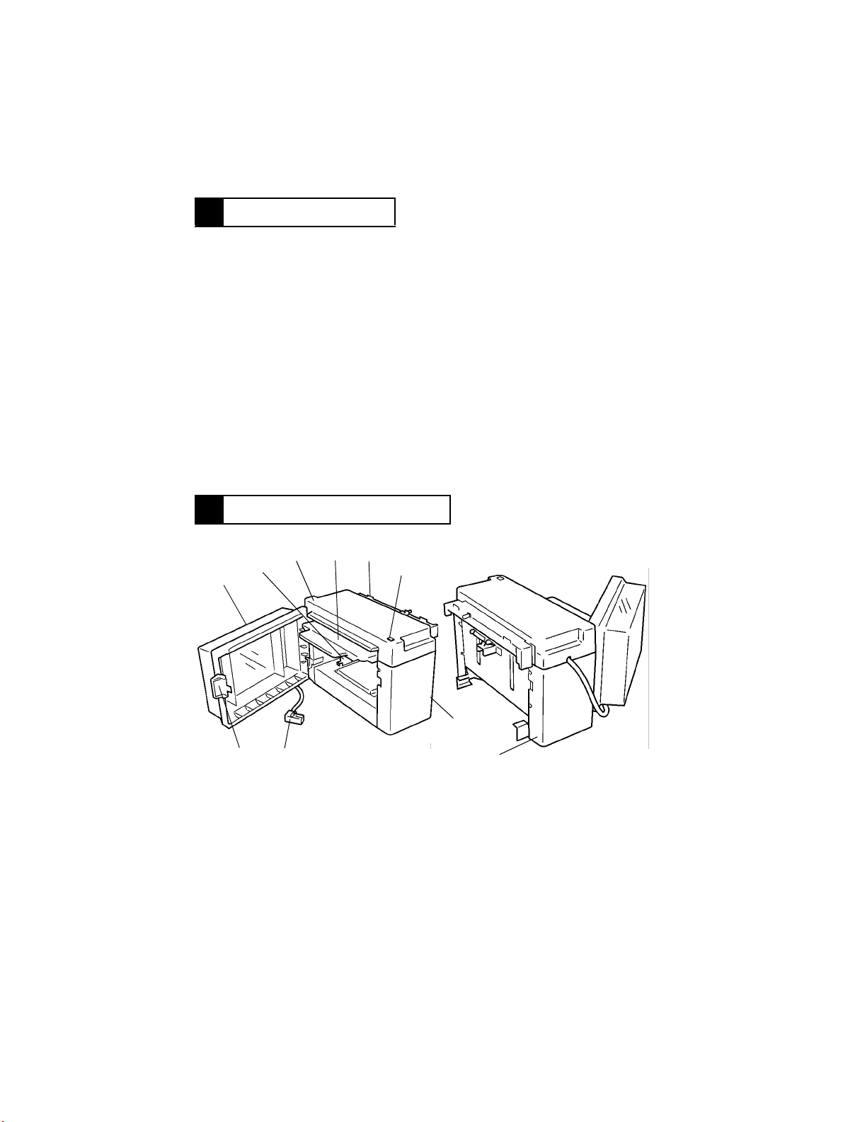
2 PARTS IDENTIFICATION
34
2
1
8
9
1. LCT Door
2. Edge Guide
3. Top Cover
4. Paper Plate
5. Paper Transport Port
5
4605M006AA
6
7
10
6. Paper Plate Descent Switch S1B
7. Front Cov er
8. Relay Cord
9. Door Unlocking Lever
10. Rear Cover
M-1
4605M007AA
Page 12
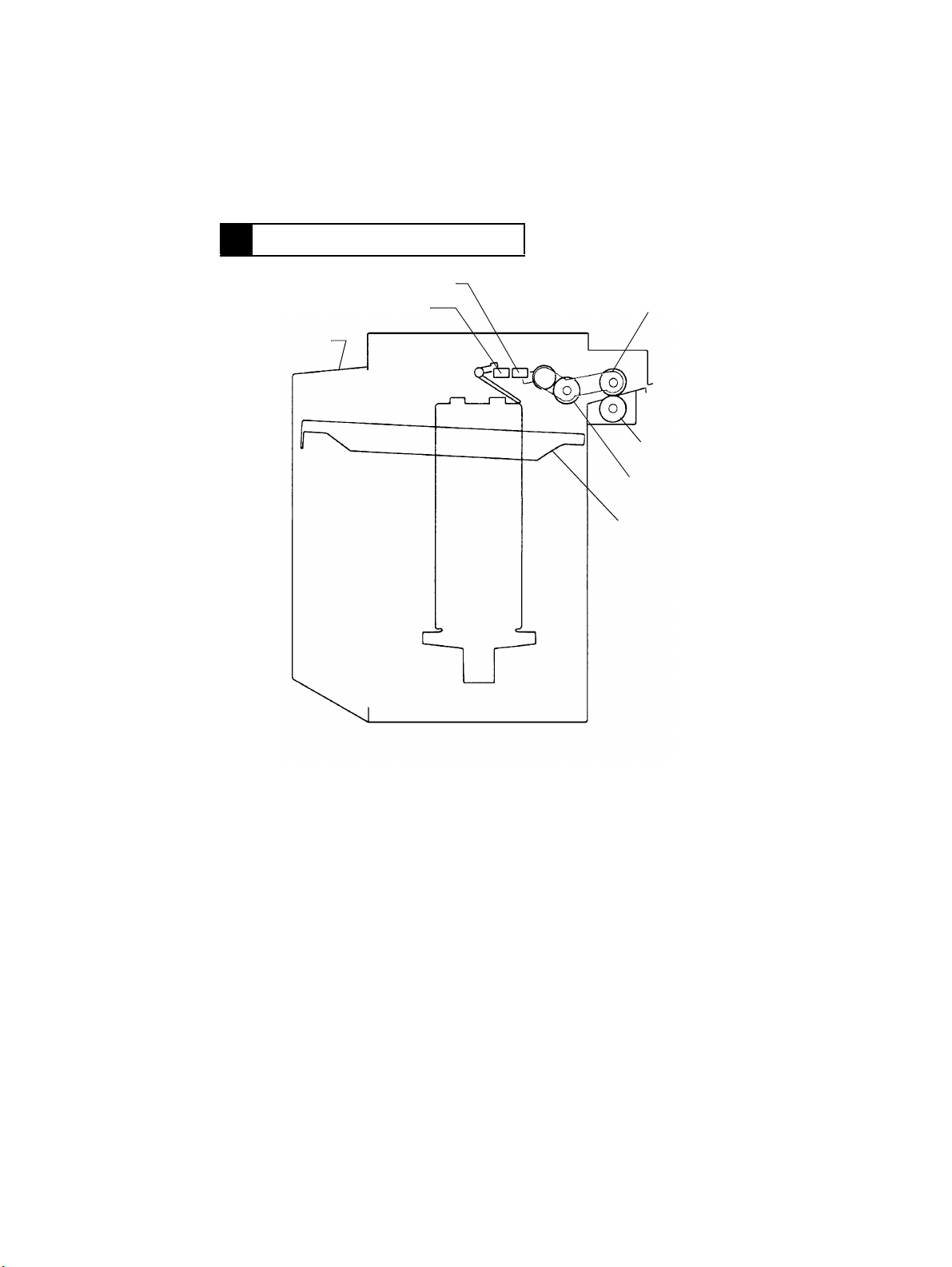
3 CROSS-SECTIONAL VIEW
Paper Plate Upper Position Sensor PC2
Paper Empty Sensor PC3
LCT Door
Edge Guide
Paper Feed Roll
Paper Separator
Roll
Paper Take-Up Roll
Paper Plate
M-2
4605M008AA
Page 13
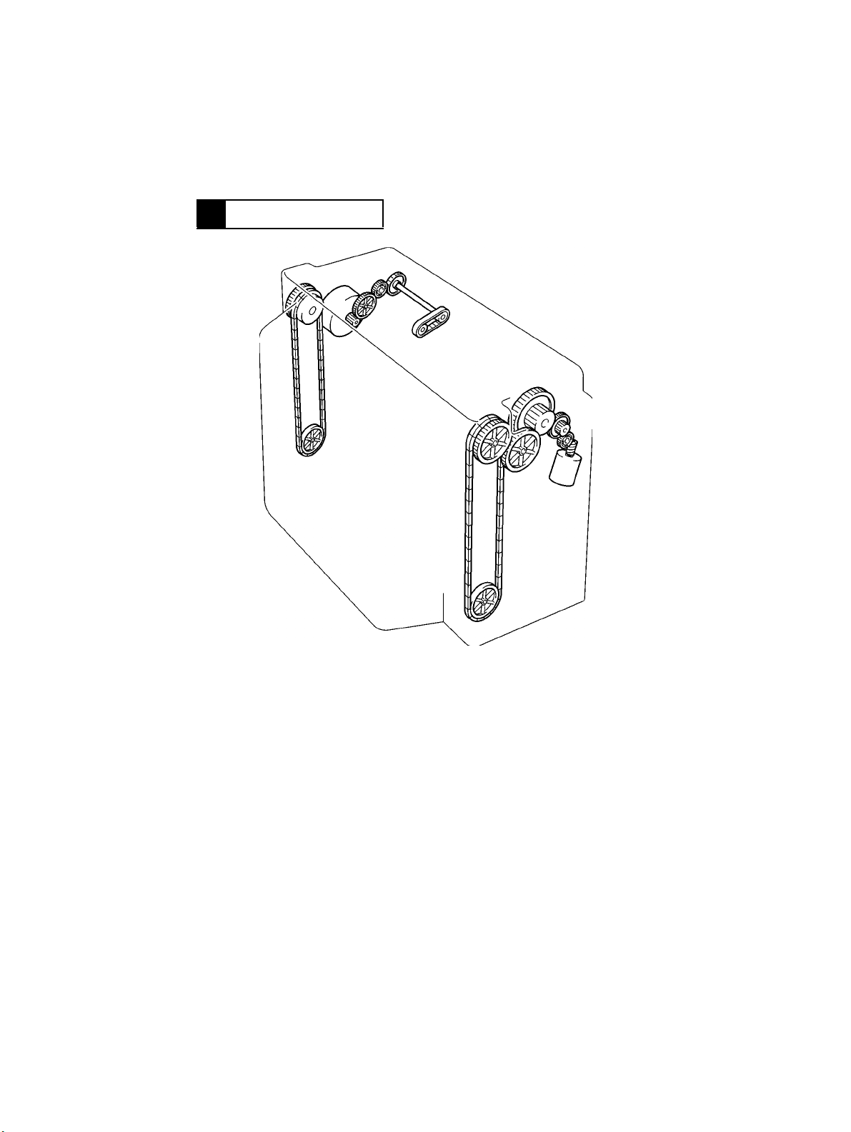
4 DRIVE SYSTEM
A
B
4605M009AA
A : Paper Take-Up Motor M2 : Drives the Paper Take-Up, Feed, and Separator Rolls.
B : Elevator Motor M1 : Moves the Paper Plate up and down.
M-3
Page 14
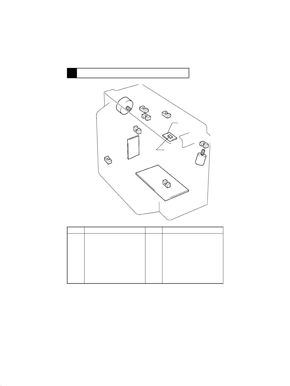
5 ELEC TRICAL COMPONENT LAYOUT
M2
PC2
PC6
PWB-A
PC4
Symbol Name Symbol Location
PWB-A
PWB-B
M1
M2
H1
S1B
Master Board
Paper Plate Descent Switch
Board
Elevator Motor
Paper Take-Up Motor
Paper Dehumidifier Heater
Paper Plate Descent Switch
PC3
PC1
PC2
PC3
PC4
PC5
PC6
PC7
PC5
PWB-B
S1B
H1
PC7
Elevator Pulse Sensor
Paper Plate Upper Position
Sensor
Paper Empty Sensor
Paper Plate Lower Position
Sensor
Paper Take-Up Sensor
LCT Set Detecting Sensor
LCT Door Open/Close Detecting
Sensor
M1
4605M010AA
PC1
M-4
Page 15
6 MECHANICAL DESCRIPTIONS
6-1. Mechanical Operation and Control of Paper Plate Lifting
•
The Paper Plate is moved up and do wn by the chains and gears which are driven by Elevator Motor M1.
< M1 Tur ning Forward = Ascent >
Paper Plate Upper Position Sensor PC2
Elevator Motor M1
4605M011AA
< M1 Turning Backward = Descent >
Paper Plate
Lower Position
Sensor PC4
4605M012AA
M-5
Page 16
<Mechanical Operation>
- Ascent Motion -
The LCT Door is closed.
(LCT Door Open/Close Detecting Sensor PC7 is blocked L.)
Elevator Motor M1 turns forward. (The Paper Plate starts its ascent motion.)
The Paper Plate moves up and the paper stack blocks L Paper Plate
M1 is deenergized. (The Paper Plate completes its ascent motion.)
The Paper Take-Up Roll gradually lowers to eventually unbloc k H PC2.
M1 turns forward to raise the Paper Take-Up Roll, thus blocking L PC2.
✽
This sequence of operations is repeated to maintain a given pressure
between the paper stack and Paper Take-Up Roll.
Paper Plate Descent Switch S1B is actuated or paper runs out.
M1 turns backward. (The Paper Plate starts its descent motion.)
The Paper Plate lowers to block L Paper Plate Lower Position Sensor PC4.
M1 is deenergized. (The Paper Plate completes its descent motion.)
Upper Position Sensor PC2.
- Paper Take-Up Sequence -
Sheets of paper are taken up.
M1 is deenergized.
- Descent Motion -
<Control>
•
M1 is turned forward, backward, stopped, and braked by the signals output from IC1A-42
and 43 on Master Board PWB-A.
M1
Forward (Ascent) H L
Backward (Descent) L H
Stopped H H
Braked L L
IC1A
Pin 42 Pin 43
M-6
Page 17
6-2. Mechanical Operation and Control of Paper T a ke-Up, Sep-
aration, and Transport
<Paper Take-Up Mechanical Operation>
The Start key is pressed. (The copy cycle is started.)
Paper Take-Up Motor M2 is energized.
Drive from M2 is transmitted via gears and belt.
The Paper Feed, Separator, and Take-Up Rolls turn counterclockwise.
Paper is transported through the LCT.
Paper Take-Up Motor M2
Paper Take-Up Roll
4605M013AA
Paper Feed Roll
Paper Separator Roll
4605M002AA
M-7
Page 18
<Paper Separation Mechanical Operation>
•
When two or more sheets of paper are taken up by the Paper Take-Up Roll, the paper
separating mechanism prevents the second and subsequent sheets of paper from being
fed together with the first one. The mechanism consists of the Paper Feed Roll, Paper
Separator Roll, and torque limiter.
•
When only one sheet of paper is taken up:
The turning torque of the Paper Feed Roll is transmitted to the Paper Separator Roll via
the sheet of paper being fed in; however, it is greater than the static torque of the Paper
Separator Roll (torque limiter), which causes the Paper Separator Roll to be turned by
the Paper Feed Roll, thus transporting the sheet of paper.
•
When two or more sheets of paper are taken up at the same time:
The coefficient of friction between the first sheet and the second and subsequent sheets
of paper is small and the static torque of the torque limiter keeps the Paper Separator
Roll stationary .This stops the second and subsequent sheets of paper from being fed in,
allowing only the first sheet of paper to be fed in.
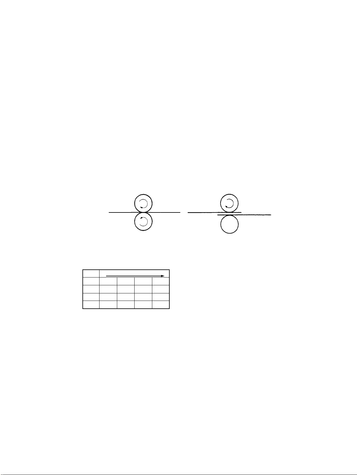
- Single-Sheet Feed - - Multiple-Sheet Feed -
1285M012
<Paper Take-Up Control>
•
Rotation of Paper Take-Up Motor M2 is controlled by the pulse signals output from IC2A1, 2, 4, and 17 of Master Board PWB-A.
IC2A Rotation
1LLHH
2HHL L
17 L H H L
4HL LH
1285M013
M-8
Page 19

6-3. Paper Empty Detecting Mechanism
<Paper Empty Detection Timing>
1. The LCT Door is opened.
2. Paper Plate Descent Switch S1B is pressed under normal operating conditions.
3. Paper Empty Sensor PC3 is blocked.
If Paper Plate Upper Position Sensor PC2 is unblocked when PC3 is blocked, the Paper
Plate is then lowered until Paper Plate Lower Position Sensor PC4 is blocked.
<Resetting Paper Empty Condition>
1. Close the LCT Door.
2. Add paper (if the LCT has run out of paper).
Paper Plate Upper Position Sensor PC2
Paper Empty Sensor PC3
1258M020AA
M-9
Page 20

<Paper Empty Sensor PC3>
When Paper is Present When Paper in not Present
4605M003AA
1258M021AA
Paper Plate Upper Position Sensor PC2
When Top Level is Detected When Top Level is not Detected
4605M004AA
4605M005AA
6-4. Paper Dehumidifier Heater
•
When paper in the LCT grows damp, its electrical resistance is decreased, which aggravates the image transfer efficiency resulting in void image and other image problems.
The Paper Dehumidifier Heater (20W) is provided to prevent this problem.
•
The heater is turned ON when the power cord of the copier is plugged in, and kept ON at
all times except while the copier Main Motor M1 remains energized.
M-10
Page 21

DIS/REASSEMBLY,
ADJUSTMENT
Precautions for Disassembly, Reassembly, and Adjustment
CAUTION
1. Before attempting to disassemble the LCT, always make sure that no power is being
supplied from the copier.
2. While power is being supplied to the LCT, do not attempt to remove/install the print
jacks from/to the PWBs or unplug/plug in the connectors.
3. If the LCT is run with its covers removed, use care not to allow your clothing to be
caught in revolving parts.
4. The basic rule is do not run the LCT with any of its parts removed.
5. A toothed washer is used with the screw that secures the ground wire to ensure positive
conduction. Do not forget to include this washer at reassembly.
6. To reassemble the LCT, reverse the order of disassembly unless otherwise specified.
7. Do not attempt to remove or loosen the screws to which red paint has been applied.
8. Screws to which blue paint has been applied may be removed; howev er, be sure to
make an adjustment after reinstalling the screws.
Purpose of Application of Red Paint
Red paint is applied to the screws of parts that cannot be readjusted, set, or reinstalled in
the field.
Page 22

Page 23

1 DISASSEMBLY
Important
The Paper Plate must be lowered before attempting to start the disassembly procedures.
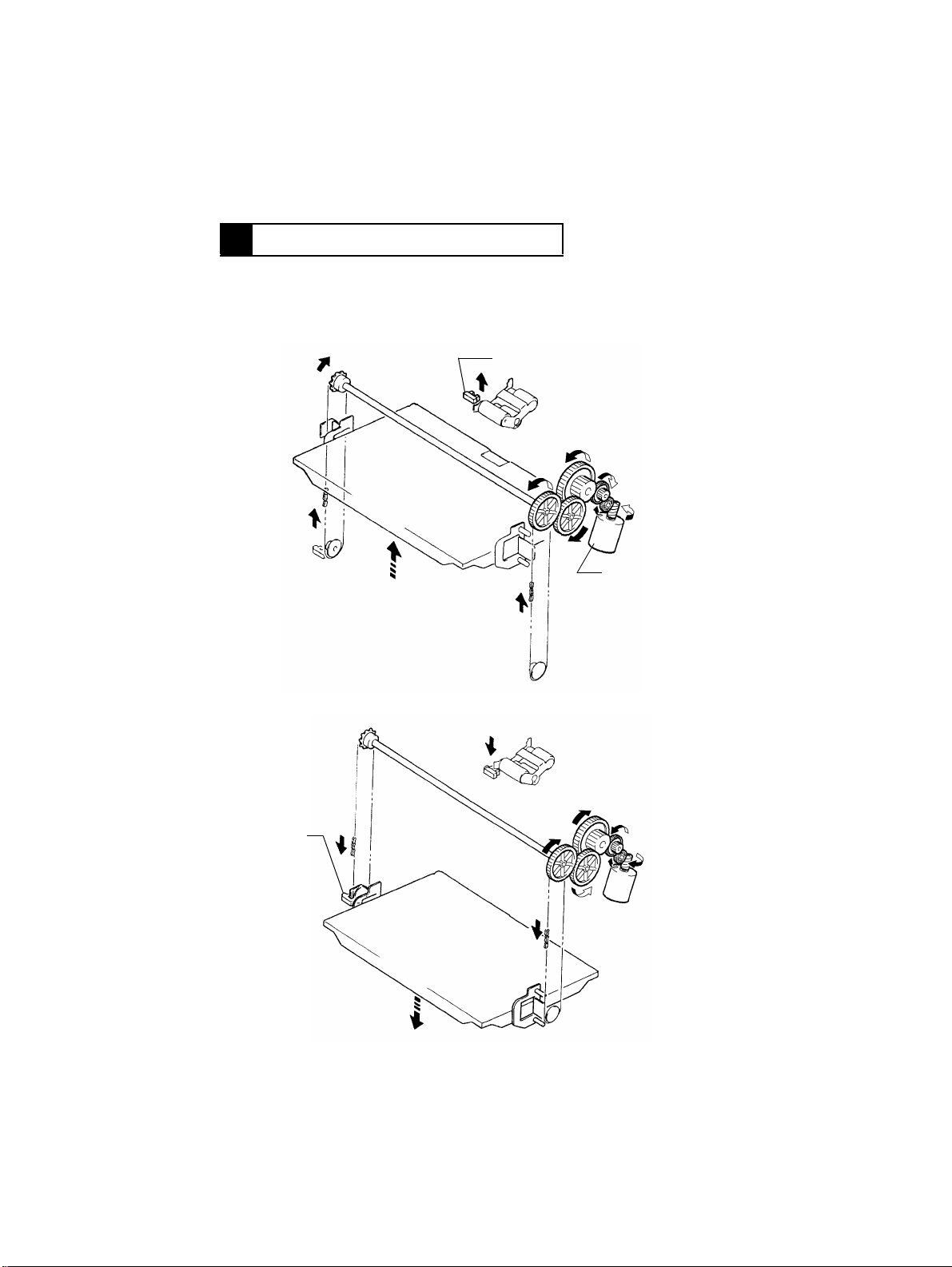
1. Removal of the Paper Take-Up/Feed Rolls
1. Remove the Top Cover.
NOTE:
Unplug the connector for Paper Plate Descent
Switch S1B.
4605D001AA
2. Snap off the C-clip from the Paper Feed Roll shaft
and remove the timing belt.
4605D002AA
3. Unhooking the springs in the Paper Separator Roll
unit, slide the Paper Take-Up Roll Assy and
remove the bushing to remove the Paper Take-Up
Roll Assy.
4605D003AA
4605D004AA
NOTE:
When the Paper Take-Up Roll Assy, use care not to
allow it to hit against Paper Plate Upper Position Sensor PC2.
4. Remove the Paper Feed Roll and one-way clutch.
D-1
Page 24

5. Snap off the C-clip and pull out the Paper Take-Up
4605D005AA
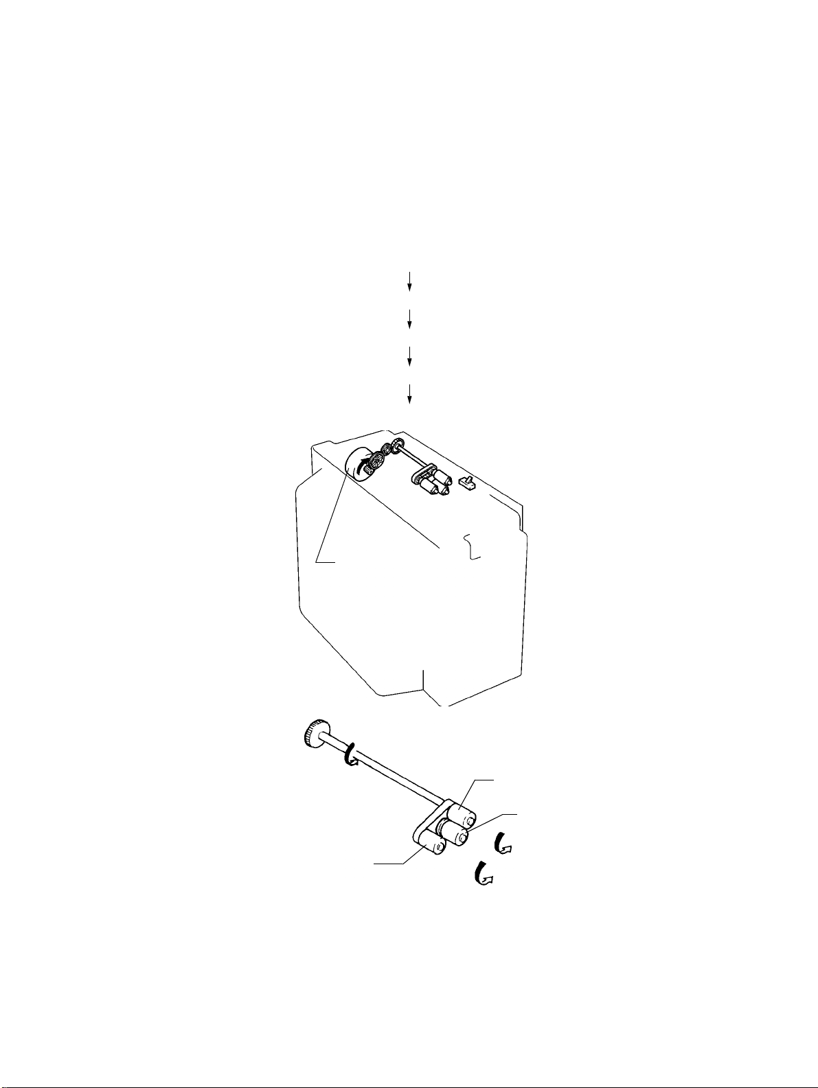
2. Removal of the Paper Separator Roll
1. Remove one screw that secures the Paper Separa-
4605D006AA
2. Unhooking the springs in the Paper Separator Roll
4605D007AA
Roll shaft to remove the Paper Take-Up Roll.
tor Roll Assy.
unit, remove the Paper Separator Roll Assy.
1258D013AA
4605D008AA
3. Snap off the E-rings and remove the bushings on
both ends. Then, remove t he P aper Separator Roll
shaft.
4. Snap off the E-ring and remove the Paper Separator Roll.
D-2
Page 25

2 PAPER WIDTH CONVERSION
1. Bring the Paper Plate to its uppermost position.
Slide the LCT away from the copier and remove
the LCT Door.
4605U011AA
2. Loosen the two screws. Then, with the Top Cover
slightly raised, unplug the connector of Paper Plate
Descent Switch S1B.
Remove the Top Cover.
4605U012AA
3. Remove the positioning screws of Edge Guides.
4605U013AA
4605U014AA
4. Remove the Edge Guides.
D-3
Page 26

AC D D CA
B
B
4605U015AA
4605U013AA
4605U012AA
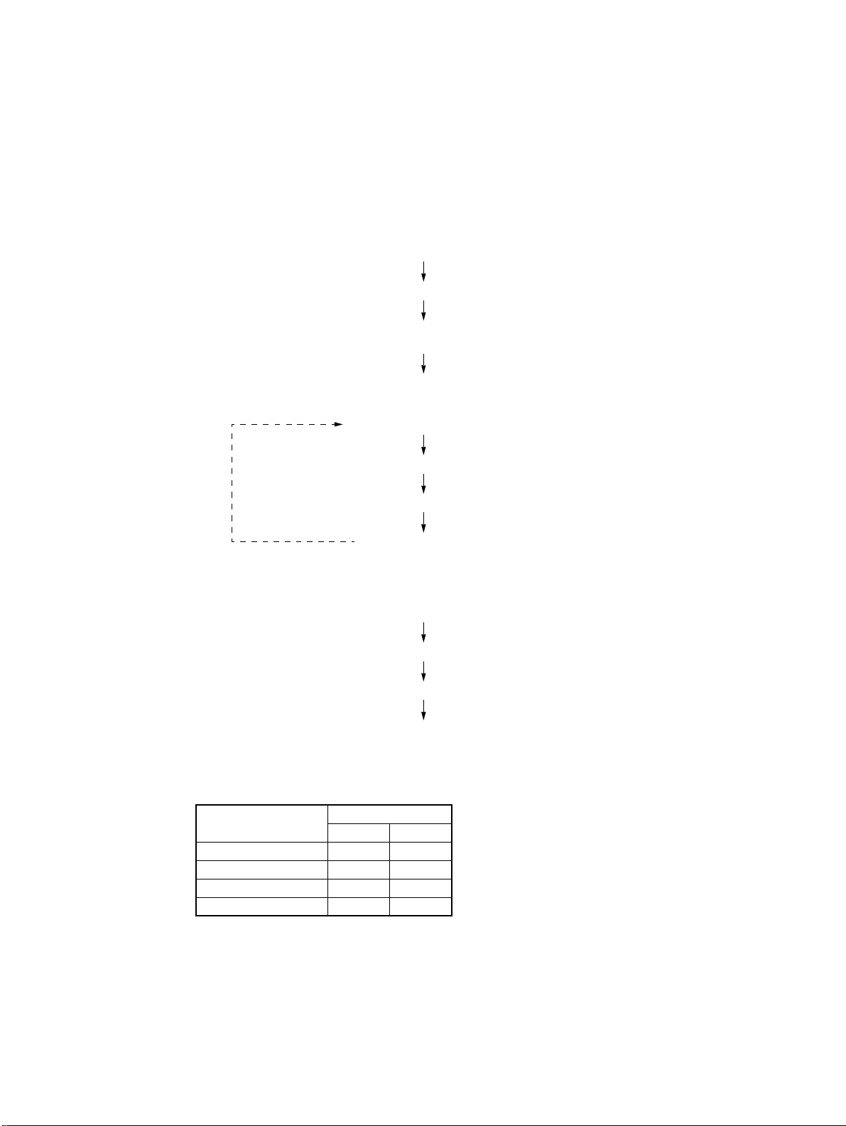
5. Fit the Edge Guides into the slots corresponding to
the paper size to be used.
- Slot-to-Paper-Size Correspondence A ... A4 cross wise
B ... Letter crosswise
C ... B5 crosswise
D ... B5 lengthwise
6. Slightly raising the Edge Guides, tighten the positioning screws.
7. Connect the Top Cover connector and reinstall the
Top Cover.
8. Reinstall the LCT Door.
4605U011AA
D-4
Page 27

3 IMAGE POSITION ADJUSTMENT
1. Set the copier into the Service mode and select
“Machine Adjust.”
4605D021CA
2. Select “PRT Area.”
4605D022CA
3. Select “Left Margin.”
4605D023CA
4605D024CA
4. Select “LCT” and press the Start key to let the
copier start a test print cycle.
D-5
Page 28

4605D024CA
Feeding Direction
4605D020AA
4605D019AA
5. Measure the void image width on the test print.
Specifications.....3 mm±1.5 mm
6. If the measurement falls outside the specified
range, adjust the void image width using ▲or
▼
key .
Make a test print again to check for cor rect adjustment.
7. If the void image width does not fall within the
specified range even through these adjustments on
the Touch Panel, move the Rail Assy to the rear or
front to make a mechanical adjustment.
D-6
Page 29

MISFEED DETECTION&
MALFUNCTION DETECTION
General Precautions
CAUTION
1. When servicing the LCT with its covers removed, use utmost care to prevent your
hands, clothing and tools from being caught in revolving parts.
2. Before attempting to replace parts and unplugging connectors, make sure that no
power is being supplied from the copier.
3. In whatever situations, terminals and PWB patterns other than connectors specified in
the text must not be shorted.
4. When creating a closed circuit and measuring a voltage across connector pins specified in the text, be sure to use the green wire (GND).
5. Keep all disassembled parts in good order and keep tools under control so that none
will be lost or damaged.
Reading the Text
1. If a component on a PWB or any other functional unit including a motor is defective, the
text only instructs you to replace the whole PWB or functional unit and does not give
troubleshooting procedure applicable within the defective unit.
2. The text assumes that there are no breaks and shorts in the harnesses and all connectors are plugged into the right positions.
Page 30

Page 31

- Sensor Check Procedure -
<Procedure>
1. When a paper misfeed or malfunction occurs, identify the possibly defective controlled
part or parts on the circuit diagram.
2. Open the “State Confirm” screen, as selected from the Service Mode menu. Then,
show the screen that contains the part or parts picked out in step 1) from among Switch
1 (Paper) or Switch 2 (Option).
3. Force to change the status of the sensor selected and check at that time that the signal
state changes on the screen.
Example
If Paper Take-Up Sensor PC5 is considered defective when a paper misfeed occur s:
<Procedure>
1. Remove the sheet of misfed paper.
2. Select “Switch 2 (Option)” of “State Confirm” available from the Service mode.
4605D025CA
3. Check that Pap. Trans is Off on the screen.
4. Move the PC5 actuator with a sheet of paper to block PC5.
5. Check that the state of Pap. Trans. has changed to On from Off.
On: PC5 is operational.
Set : LCT-to-copier connector
Path Set : LCT Set Detecting Sensor PC6
Cover Open : LCT Door Open/Close Detecting Sensor PC7
Pap. Empty : Paper Empty Sensor PC3
Upr. Limit : Paper Plate Upper Position Sensor PC2
Lwr. Limit : Paper Plate Lower Position Sensor PC4
Pap. Trans : Paper Take-Up Sensor PC5
Off: PC5 is defective
T-1
Page 32

1 PAPER MISFEED DETECTION
1-1. Misfeed Detection Timing
Type Detection Timing
Paper left When the copier Power Switch is turned ON or a paper misfeed
Paper take-up failure
detection
Paper take-up trailing
edge detection
1-2. Misfeed Troubleshooting Procedures
1. Misfeed Before Start of Copy Cycle (Paper Left)
Step Check Item Result Action
1 Is there a sheet of paper being fed
in the LCT, blocking the sensor?
LCT paper take-up section: Paper
Take-Up Sensor PC5
2 Is PC19 or PC5 mounted in a cor-
rect position, or does the sensor
actuator move correctly?
3 Does PWB-I receive the output sig-
nal of PC19 or PC5 properly?
PC19: PWB-I on copier
PC5: PWB-I on copier
PC19: If “Front Mid” fully operational when checked with Switch 1
(Paper)?
PC5: If “Pap. Trans.” fully operational when checked with Switch 2
(Option)?
or malfunction is reset, Paper Take-Up Sensor PC5 or Transport Roller Sensor PC19 is unblocked (H).
PC5 is not unblocked (H) even after the lapse of about 1 sec.
after Paper Take-Up Motor M2 has been energized.
PC5 is not blocked (L) even after the lapse of about 4.5 sec.
after it has been unblocked (H).
YES Remove the sheet of paper being
fed.
NO Check the mounting position or
actuator.
YES Replace PWB-A (C-101) or PWB-I
(copier).
NO Check the wiring between PWB-I
and sensor and, if it is intact,
change PC19 or PC5.
T-2
Page 33

2. Misfeed After Copy Cycle Has Been Started
Step Check Item Result Action
1 Does the paper being used meet
product specifications?
2 Is the paper curled, waved, or
damp?
3 Does Paper Take-Up Motor M2 turn
when the Start key is pressed?
4 Is a drive voltage output from PWB-
A to M2?
Does the voltage across PJ6A-4
and GND change from approx.
DC0V when a paper misfeed is
reset and Start key pressed?
5 Is the Paper Take-Up/Feed/Separa-
tor Roll dirty, worn, or deformed?
6 Is the guide plate along the paper
path dirty or deformed?
7 Is Transport Roller Sensor PC19 or
PC5 mounted at the correct position? Does the sensor actuator
make a correct motion?
8 Does PWB-I receive the output sig-
nal of PC19 or PC5 properly?
PC19: PWB-I on copier
PC5: PWB-I on copier
PC19: If “Front Mid” fully operational when checked with Switch 1
(Paper)?
PC5: If “Pap. Trans.” fully operational when checked with Switch 2
(Option)?
NO Instruct the user to use paper that
meets product specifications.
YES Change the paper. Instruct the
user in how to store the paper.
YES Check each part for possible over-
load.
YES Check the wiring between PWB-A
and M2 and, if it is intact, change
M2.
NO Change PWB-A.
YES Clean or change the defective roll.
YES Clean, correct, or change the
defective guide plate.
NO Check the mounting position or
actuator.
YES Replace PWB-A (C-101) or PWB-I
(copier).
NO Check the wiring between PWB-I
and sensor and, if it is intact,
change PC19 or PC5.
✽
: If these procedures do not remedy the problem, check the copier. (See TROUBLE-
SHOOTING of the copier service manual.)
T-3
Page 34

2 MALFUNCTION DETECTION
2-1. Malfunction Detection Timing
Malfunction Code Malfunction Detail Detection Timing
Paper Plate Upper
Position Sensor PC2
is not activated.
C09XX
Elevator
malfunction
C0
Paper Plate Lower
C2
Position Sensor PC4
is not activated.
2-2. Malfunction Troubleshooting Procedures
1. C09C0
Step Check Item Result Action
1 Does the Paper Plate lower after the
malfunction has been reset?
2 Is PC2 or PC3 mounted at the correct
position? Does the sensor actuator
make a correct motion?
3 PC2: If “Upr. Limit” fully operational
when checked with Switch 2 (Option)?
4 Does PWB-I receive the output signal
from PC3 correctly?
Does the voltage across PJ4A-8B and
GND change from DC0V to DC5V
when PC3 is unblocked?
5 Does the drive transmission mecha-
nism from M1 remain intact?
6 Is a signal output from PWB-A to M1?
Does the voltage across ✽ and GND
change from DC0V to DC24V when
the malfunction is reset and the copier
Front Door opened and closed?
✽
During ascent: PJ2A-2
During descent: PJ2A-1
•
PC2 is not blocked (L) e v en after the lapse of
10 sec. after Elevator Motor M1 has been
energized.
•
PC2 is not blocked (L) e v en after the lapse of
3 sec. after Paper Empty Sensor PC3 has
been unblocked (H).
•
PC4 is not blocked (L) e v en after the lapse of
10 sec. after M1 has been energized.
NO Go to step 5.
NO Check the mounting position or
actuator.
YES Change PWB-A (C-101) or
PWB-I (copier).
NO Check the wiring between
PWB-I and sensor and, if it is
intact, change PC2.
YES Change PWB-A (C-101) or
PWB-I (copier).
NO Check the wiring between
PWB-I and sensor and, if it is
intact, change PC3.
NO Check the drive transmission
mechanism (gears, chains,
etc.) from M1.
YES Check the wiring between
PWB-A and sensor and, if it is
intact, change M1.
NO Change PWB-A.
✽
: If these procedures do not remedy the problem, check the copier. (See TROUBLE-
SHOOTING of the copier service manual.)
T-4
Page 35

2. C09C2
Step Check Item Result Action
1 Does the P aper Plate lo wer after the malfunction
has been reset?
2 Is PC4 mounted at the correct position? Does
the sensor actuator make a correct motion?
3 PC4: If “Lwr. Limit” fully operational when
checked with Switch 2 (Option)?
4 Does the drive transmission mechanism from
M1 remain intact?
5 Is a signal output from PWB-A to M1? Does the
voltage across ✽ and GND change from DC0V
to DC24V when the malfunction is reset and the
copier Front Door opened and closed?
✽
During ascent : PJ2A-2
During descent : PJ2A-1
✽
: If these procedures do not remedy the problem, check the copier. (See TROUBLE-
SHOOTING of the copier service manual.)
NO Go to step 5.
NO Check the mounting
position or actuator.
YES Change PWB-A.
NO Check the wiring
between PWB-A and
sensor and, if it is
intact, change PC2.
NO Check the drive trans-
mission mechanism
(gears, chains, etc.)
from M1.
YES Check the wiring
between PWB-A and
sensor and, if it is
intact, change M1.
NO Change PWB-A.
T-5
Page 36

Page 37

MAINTENANCE
SCHEDULE
Page 38

Page 39

OPTIONS MAINTENANCE SCHEDULE FOR 7823
This Maintenance Schedule is intended to be used as reference information for establishing effective field service activi-
ties. To keep the copiers in as optimum a condition as possible, it is recommended that the maintenance jobs described in
this schedule be carried out.
It should be noted, however, that frequency of maintenance jobs determined by the number of copies is simply a guide-
line. Therefore, service management personnel can revise or amend this schedule by taking into account their own indi-
vidual field experiences. We feel that this will ensure more effective copier maintenance for your customers.
*The maintenance cycle numbers given below represent the readings on the PM Counter of the copier.
C : Cleaning R : Replacement Unit: 1000 Copies
All information contained in this manual is subject to change.
LT-723
NOTE: K = 1,000 copies
PM Parts
Maintenance Cycle (K)
Parts No. QTY Reference Page
C R
Paper Take-Up Roll 100 200 11UW45430 1 D-2
Paper Feed Roll 100 200 11UW45430 1 D-2
Separator Roll Assy 100 200 11UW45510 1 D-2
Page 40

Page 41

WIRING
DIAGRAMS
Page 42

Page 43

W-1
Page 44

W-2
Page 45

PARTS CATALOG
Model
LT-723
FEBRUARY 1999
KONICA BUSINESS TECHNOLOGIES, INC.
Page 46

Page 47

How to use this catalog
This parts catalog includes illustrations and part numbers for all replacement parts and assemblies used in this model.
Model-specific parts are identified in the illustrations with reference
numbers. Use the reference number to locate the corresponding part
number on the facing page.
Common hardware items, such as screws, nuts, washers, and pins, are
identified in the illustrations with reference letters. Use the reference letter to locate the corresponding part number on the hardware listing in the
lower right hand corner of the facing page.
If you know a part number, but don’t know where the part is used, use
the numerical index to determine the page number and reference number for that part. Because some common parts are used in several
places, there may be more than one entry. Refer to the illustrations to see
where the part may be used.
If you know a part’s description, but don’t know where to look to find
the part number, use the alphabetical index to determine likely page and
reference numbers. Then look at the illustrations to determine that you
have identified the correct part. Locate the part number using the listing
on the opposite page.
Retail pricing that appears with the numerical index, while valid when
this catalog was printed, is subject to change without notice. The prices
are only suggested prices and are provided only for reference. Dealers
may determine their own selling prices. For up-to-date pricing, refer to
current Konica price lists or contact the Konica Parts Distribution Center.
How to order parts
Use standard Konica parts ordering procedures to obtain these parts. For
ordering options, contact Konica’s Parts Distribution Center.
When ordering parts, be sure to specify part numbers exactly as listed in
this catalog.
NOTE: Electrical parts may include previously used components.
Model LT-723 Konica Business Technologies, Inc. Page iii
1st Edition February, 1999
Page 48

This page left blank intentionally.
Page iv Konica Business Technologies, Inc. Model LT-723
February, 1999 1st Edition
Page 49

How to use this catalog . . . . . . . . . . . . . . . . . . . . . . . . . iii
Contents . . . . . . . . . . . . . . . . . . . . . . . . . . . . . v
Machine parts
Housing . . . . . . . . . . . . . . . . . . . . . . . . . . . . . 2
Frames . . . . . . . . . . . . . . . . . . . . . . . . . . . . . 4
Paper Transport Section . . . . . . . . . . . . . . . . . . . . . 6
Alphabetical index . . . . . . . . . . . . . . . . . . . . . . . . . . . . 9
Numerical index, Retail price list . . . . . . . . . . . . . . . . . . . . 11
Contents
Model LT-723 Konica Business Technologies, Inc. Page 1
1st Edition February, 1999
Page 50

Housing
Page 2 Konica Business Technologies., Inc. Model LT-723
February, 1999 1st Edition
Page 51

REF. PART NUMBER DESCRIPTION
NO.
1 11UW97010 Label, open
2 11UW97020 Label, jam removal
3 11UW12010 Top cover
4 11UW12020 Side cover
5 11UW12030 Button
6 11UW-9010 PW board (B) (NO IC)
7 11UW12040 Door
8 11UW12050 Lock release lever
9 11UW10010 Support
10 11UW43010 Rail
HARDWARE
REF.
LTR.
a 25TU01520
b 25TU02850
c 11UW01240
PART
NUMBER
Model LT-723 Konica Business Technologies., Inc. Page 3
1st Edition February, 1999
Page 52

Frames
Page 4 Konica Business Technologies., Inc. Model LT-723
February, 1999 1st Edition
Page 53

REF. PART NUMBER DESCRIPTION
NO.
1 11UW45010 Positioning pin
2 11UW45020 Cover
3 11UW45030 Seal
4 11UW45040 Actuator
5 11UW45050 Set plate
6 11UM85010 Photosensor
7 11UW45530 Bracket
8 11UW90010 Harness
9 11UW-9020 PA board (A)
10 25TU30240 PWB support
11 25TU60860 PWB support
12 11UW45060 Bracket
13 11UW45070 Hinge (upper)
14 11UW45080 Guide roller
15 11UW97030 Label, paper maximum
16 11UW45090 Guide
17 11UW45100 Actuator
18 11UW45110 Hinge (lower)
19 11UW45120 Ground plate
20 11UW90020 Harness
21 11UW45130 Table
22 11UW45140 Polyester film
23 11UW45150 Paper plate
24 11UW45160 Bracket
25 11UW45170 Bracket
26 11UW97040 Label (Do Not Load)
27 11UW45180 Cover
28 11UW83010 Panel heater
29 11UW45190 Cover
30 12ZN44300 Label (Caution: Hot)
31 25TU40540 Holder
32 11UW45200 Polyester Film
33 11UW45210 Washer
34 11UW45220 Ground plate
35 11UW45230 Torsion spring
36 11UW45240 Actuator
37 11UW45250 Torsion spring
38 11UP10210 Stopper
39 11UW45270 Actuator
40 11UW45280 Torsion spring
41 11UW45290 Cover
42 11UW45300 Bracket
43 11UW45310 Friction sheet
44 11UW45320 Top frame
HARDWARE
REF.
LTR.
a 25TU02460
b 25TU02410
c 11UW01240
d 25TU02840
e 25TU01440
f 25TU02480
g 11UW01270
h 25TU02830
j 11UW01260
k 11UW01320
m 11UW01310
n 25TU02140
PART
NUMBER
Model LT-723 Konica Business Technologies., Inc. Page 5
1st Edition February, 1999
Page 54

Paper Transport Section
Page 6 Konica Business Technologies., Inc. Model LT-723
February, 1999 1st Edition
Page 55

REF. PART NUMBER DESCRIPTION
NO.
1 25TU75560 Bushing
2 11UW77010 Gear (Z=44)
3 11UW77020 Gear (Z=26)
4 11UW75010 Bushing
5 11UW77030 Gear (Z=38)
6 11UW45330 Bracket
7 11UW80010 Motor
8 11UW77040 Sprocket (Z=13)
9 11UW77050 Chain (L=65)
10 11UW45340 Mounting plate
11 11UW45350 Cover
12 11UW45360 Shaft
13 11UW77060 Gear (Z=36)
14 11UW77070 Gear (Z=32)
15 11UW77080 Gear (Z=16,20)
16 11UW80020 Motor
17 11UW45370 Cushion
18 11UW77090 Bracket
19 11UW45380 Bracket
20 11UW45390 Synchronizing disk
21 11UW77100 Gear (Z=14,63)
22 11UW77110 Gear (Z=23,45)
23 11UM85010 Photosensor
24 11UW45400 Bracket
25 11UP10210 Stopper
26 25TU42320 Stopper ring
27 11UW45420 Shaft
28 11UW45430 Roller
29 11UW45440 Collar
30 11UW45450 Holder
31 11UW75020 Bushing
32 11UW77510 Timing belt
33 11UW76510 Pulley (Z=18)
34 11UW45460 Washer
35 11UW45470 Weight
36 11UW45480 Pressure spring
37 11UW76520 Pulley (Z=21)
38 11UW45490 Shaft
39 11UW45500 Shaft
40 11UW45510 Separator roller
41 11UW45520 Holder
42 11UW00140 Cable tie
42 25TU00140 Cable tie
43 11UW00150 Edge cover
44 25TU05250 Wiring saddle
45 25TU05220 Wiring saddle
HARDWARE
REF.
LTR.
a 25TU02410
b 25TU02840
c 11UW01330
d 11UW01320
e 11UW01240
f 11UW01250
g 11UW01230
h 11UW01340
j 11UW01210
k 11UW01220
PART
NUMBER
Model LT-723 Konica Business Technologies., Inc. Page 7
1st Edition February, 1999
Page 56

This page left blank intentionally.
Page 8 Konica Business Technologies, Inc. Model LT-723
February, 1999 1st Edition
Page 57

Alphabetical index
PART PAGE REF.
DESCRIPTION NO. NO.
A
Actuator . . . . . . . . . . 5 4
Actuator . . . . . . . . . . 5 17
Actuator . . . . . . . . . . 5 36
Actuator . . . . . . . . . . 5 39
B
Bracket . . . . . . . . . . . 5 7
Bracket . . . . . . . . . . . 5 12
Bracket . . . . . . . . . . . 5 24
Bracket . . . . . . . . . . . 5 25
Bracket . . . . . . . . . . . 5 42
Bracket . . . . . . . . . . . 7 6
Bracket . . . . . . . . . . . 7 18
Bracket . . . . . . . . . . . 7 19
Bracket . . . . . . . . . . . 7 24
Bushing . . . . . . . . . . 7 1
Bushing . . . . . . . . . . 7 4
Bushing . . . . . . . . . . 7 31
Button . . . . . . . . . . . 3 5
C
Cable tie . . . . . . . . . . 7 42
Chain (L=65) . . . . . . . . 7 9
Collar . . . . . . . . . . . . 7 29
Cover . . . . . . . . . . . . 5 2
Cover . . . . . . . . . . . . 5 27
Cover . . . . . . . . . . . . 5 29
Cover . . . . . . . . . . . . 5 41
Cover . . . . . . . . . . . . 7 11
Cushion . . . . . . . . . . 7 17
D
Door . . . . . . . . . . . . 3 7
PART PAGE REF.
DESCRIPTION NO. NO.
G
Gear (Z=14,63) . . . . . . . 7 21
Gear (Z=16,20) . . . . . . . 7 15
Gear (Z=23,45) . . . . . . . 7 22
Gear (Z=26) . . . . . . . . 7 3
Gear (Z=32) . . . . . . . . 7 14
Gear (Z=36) . . . . . . . . 7 13
Gear (Z=38) . . . . . . . . 7 5
Gear (Z=44) . . . . . . . . 7 2
Ground plate . . . . . . . . 5 19
Ground plate . . . . . . . . 5 34
Guide . . . . . . . . . . . . 5 16
Guide roller . . . . . . . . . 5 14
H
Harness . . . . . . . . . . 5 8
Harness . . . . . . . . . . 5 20
Hinge (lower) . . . . . . . . 5 18
Hinge (upper) . . . . . . . . 5 13
Holder . . . . . . . . . . . 5 31
Holder . . . . . . . . . . . 7 30
Holder . . . . . . . . . . . 7 41
L
Label (Caution: Hot) . . . . 5 30
Label (Do Not Load) . . . . 5 26
Label, jam removal . . . . . 3 2
Label, open . . . . . . . . . 3 1
Label, paper maximum . . . 5 15
Lock release lever . . . . . 3 8
M
Motor . . . . . . . . . . . . 7 7
Motor . . . . . . . . . . . . 7 16
Mounting plate . . . . . . . 7 10
PART PAGE REF.
DESCRIPTION NO. NO.
Photosensor . . . . . . . . 7 23
Polyester Film . . . . . . . . 5 32
Polyester film . . . . . . . . 5 22
Positioning pin . . . . . . . 5 1
Pressure spring . . . . . . . 7 36
Pulley (Z=18) . . . . . . . . 7 33
Pulley (Z=21) . . . . . . . . 7 37
R
Rail . . . . . . . . . . . . . 3 10
Roller . . . . . . . . . . . . 7 28
S
Seal . . . . . . . . . . . . . 5 3
Separator roller . . . . . . . 7 40
Set plate . . . . . . . . . . 5 5
Shaft . . . . . . . . . . . . 7 12
Shaft . . . . . . . . . . . . 7 27
Shaft . . . . . . . . . . . . 7 38
Shaft . . . . . . . . . . . . 7 39
Side cover . . . . . . . . . 3 4
Sprocket (Z=13) . . . . . . 7 8
Stopper . . . . . . . . . . . 5 38
Stopper . . . . . . . . . . . 7 25
Stopper ring . . . . . . . . 7 26
Support . . . . . . . . . . . 3 9
Synchronizing disk . . . . . 7 20
T
Table . . . . . . . . . . . . 5 21
Timing belt . . . . . . . . . 7 32
Top cover . . . . . . . . . . 3 3
Top frame . . . . . . . . . . 5 44
Torsion spring . . . . . . . . 5 35
Torsion spring . . . . . . . . 5 37
Torsion spring . . . . . . . . 5 40
E
Edge cover . . . . . . . . . 7 43
F
Friction sheet . . . . . . . . 5 43
P
PA board (A) . . . . . . . . 5 9
PW board (B) (NO IC) . . . 3 6
PWB support . . . . . . . . 5 10
PWB support . . . . . . . . 5 11
Panel heater . . . . . . . . 5 28
Paper plate . . . . . . . . . 5 23
Photosensor . . . . . . . . 5 6
Model LT-723 Konica Business Technologies, Inc. Page 9
1st Edition February, 1999
W
Washer . . . . . . . . . . . 5 33
Washer . . . . . . . . . . . 7 34
Weight . . . . . . . . . . . 7 35
Wiring saddle . . . . . . . . 7 44
Wiring saddle . . . . . . . . 7 45
Page 58

This page left blank intentionally.
Page 10 Konica Business Technologies, Inc. Model LT-723
February, 1999 1st Edition
Page 59

Numerical index
PART PAGE REF.SUGGESTED
NUMBER NO. NO. RETAIL
11UM85010 . . . 5 6
11UM85010 . . . 7 23
11UP10210 . . . 5 38
11UP10210 . . . 7 25
11UW-9010 . . . 3 6
11UW-9020 . . . 5 9
11UW00140 . . . 7 42
11UW00150 . . . 7 43
11UW10010 . . . 3 9
11UW12010 . . . 3 3
11UW12020 . . . 3 4
11UW12030 . . . 3 5
11UW12040 . . . 3 7
11UW12050 . . . 3 8
11UW43010 . . . 3 10
11UW45010 . . . 5 1
11UW45020 . . . 5 2
11UW45030 . . . 5 3
11UW45040 . . . 5 4
11UW45050 . . . 5 5
11UW45060 . . . 5 12
11UW45070 . . . 5 13
11UW45080 . . . 5 14
11UW45090 . . . 5 16
11UW45100 . . . 5 17
11UW45110 . . . 5 18
11UW45120 . . . 5 19
11UW45130 . . . 5 21
11UW45140 . . . 5 22
11UW45150 . . . 5 23
11UW45160 . . . 5 24
11UW45170 . . . 5 25
11UW45180 . . . 5 27
11UW45190 . . . 5 29
PART PAGE REF.SUGGESTED
NUMBER NO. NO. RETAIL
11UW45200 . . . 5 32
11UW45210 . . . 5 33
11UW45220 . . . 5 34
11UW45230 . . . 5 35
11UW45240 . . . 5 36
11UW45250 . . . 5 37
11UW45270 . . . 5 39
11UW45280 . . . 5 40
11UW45290 . . . 5 41
11UW45300 . . . 5 42
11UW45310 . . . 5 43
11UW45320 . . . 5 44
11UW45330 . . . 7 6
11UW45340 . . . 7 10
11UW45350 . . . 7 11
11UW45360 . . . 7 12
11UW45370 . . . 7 17
11UW45380 . . . 7 19
11UW45390 . . . 7 20
11UW45400 . . . 7 24
11UW45420 . . . 7 27
11UW45430 . . . 7 28
11UW45440 . . . 7 29
11UW45450 . . . 7 30
11UW45460 . . . 7 34
11UW45470 . . . 7 35
11UW45480 . . . 7 36
11UW45490 . . . 7 38
11UW45500 . . . 7 39
11UW45510 . . . 7 40
11UW45520 . . . 7 41
11UW45530 . . . 5 7
11UW75010 . . . 7 4
11UW75020 . . . 7 31
PART PAGE REF.SUGGESTED
NUMBER NO. NO. RETAIL
11UW76510 . . . 7 33
11UW76520 . . . 7 37
11UW77010 . . . 7 2
11UW77020 . . . 7 3
11UW77030 . . . 7 5
11UW77040 . . . 7 8
11UW77050 . . . 7 9
11UW77060 . . . 7 13
11UW77070 . . . 7 14
11UW77080 . . . 7 15
11UW77090 . . . 7 18
11UW77100 . . . 7 21
11UW77110 . . . 7 22
11UW77510 . . . 7 32
11UW80010 . . . 7 7
11UW80020 . . . 7 16
11UW83010 . . . 5 28
11UW90010 . . . 5 8
11UW90020 . . . 5 20
11UW97010 . . . 3 1
11UW97020 . . . 3 2
11UW97030 . . . 5 15
11UW97040 . . . 5 26
12ZN44300 . . . . 5 30
25TU00140 . . . . 7 42
25TU05220 . . . . 7 45
25TU05250 . . . . 7 44
25TU30240 . . . . 5 10
25TU40540 . . . . 5 31
25TU42320 . . . . 7 26
25TU60860 . . . . 5 11
25TU75560 . . . . 7 1
Model LT-723 Konica Business Technologies, Inc. Page 11
1st Edition February, 1999
Page 60

This page left blank intentionally.
Page 12 Konica Business Technologies, Inc. Model LT-723
February, 1999 1st Edition
 Loading...