

Page 1

SERVICE MANUAL
Models
LT-402/LT-412
JANUARY 2004
CSM-LT402
KONICA MINOLTA BUSINESS SOLUTIONS U.S.A., INC.
Page 2

Page 3

LT-402/LT-412
SERVICE MANUAL
JANUARY 2004
Used on Konica Models
7155/7165/7255/7272
Page 4

IMPORTANT NOTICE
Because of the possible hazards to an inexperienced
person servicing this equipment, as well as the risk of
damage to the equipment, Konica Minolta Business
Solutions U.S.A., Inc. strongly recommends that all
servicing be performed by Konica-trained service technicians only.
Changes may have been made to this equipment to
improve its performance after this service manual was
printed. Accordingly, Konica Minolta Business Solutions U.S.A., Inc., makes no representations or warranties, either expressed or implied, that the information contained in this service manual is complete or
accurate. It is understood that the user of this manual
must assume all risks or personal injury and/or damage to the equipment while servicing the equipment for
which this service manual is intended.
Corporate Publishing Department
© 2004, KONICA MINOLTA BUSINESS SOLUTIONS U.S.A., INC.
All rights reserved.
Printed in U.S.A.
Page 5

CONTENTS
CONTENTS
SAFETY AND IMPO RTANT WARNING ITEMS
Refer to the 7155/7165/7255/7272 Service Manual
1. OUTLINE
LT-402/LT-412 PRODUCT SPECIFICATIONS.........1-1
CENTER CROSS-SECTIONAL DRAWING..............1-2
DRIVE SYSTEM DRAWING......... ............... ..............1-3
[1] Paper feed drive section.. .. ................... ......1-3
[2] Stacked paper up/down wire drive section.1-4
2. UNIT EXPLANATION
PAPER FEED SECTION...........................................2-1
[1] Composition ...............................................2-1
[2] Mechanisms ...............................................2-1
[3] First paper feed control ..............................2-2
[4] Up/down plate drive control........................2-4
[5] Remaining paper detection/No paper
detec tio n control.........................................2-5
3. DISASSEMBLY/ASSEMBLY
PAPER FEED SECTION...........................................3-1
[1] Cleaning the Paper Dust Removing Brush.3-1
[2] Cleaning the LT feed PS (PS106)/
LT first pa pe r feed P S(PS1 07 ) ...................3-1
[3] Removing and Reinstalling the
Paper Feed Roller Unit...............................3-2
[4] Replacing the Paper Feed Roller Rubber/
Feed Roller Rubber....................................3-2
[5] Replacing the Double Feed
Prevention Roller Rubb er...........................3-3
[6] Replacing the LT feed MC (MC101)/
LT first pa pe r feed MC (MC102)..... ............3-5
[7] Replacing the LT-402 Up/Down Wires .......3-6
[8] Replacing the LT-412 Up/Down Wires .....3-10
Page 6

Blank page
Page 7

SAFETY WARNINGS
[1] Modifications Not Authorized by
Konica Minolta
Konica Minolta equipment is renowned for their high
reliability. This reliability is achieved through high-quality
design and a solid service network.
Unauthorized modifications involve a high risk of degrading performance and safety. Such modifications are therefore strictly prohibited. The points listed below are not
exhaustive, but they illustrate the reasoning behind this
policy.
PROHIBITED ACTIONS :
(1) Using extension cables or a different power cord
than specified by Konica Minolta.
(2) Using other fuses than specified by Konica
Minolta. Safety will not be assured, leading to a
risk of fire and injury.
(3) Disabling fuses or bridging fuse terminals with
wire, metal clips, solder or similar. (This applies
also to thermal fuses.)
(4) Removing air filters (except for replacement).
(5) Disabling relay functions (such as wedging pa-
per between relay contacts, etc.).
(6) Disabling safety functions (interlocks, safety cir-
cuits, etc.). Safety will not be assured, leading to
a risk of fire and injury.
(7) Performing actions to equipment not described
in the instruction manual or the service hand-
book.
(8) Using parts other than specified by Konica
Minolta.
[2] Checkpoints When Performing On-
site Service
Konica Minolta equipment is extensively tested before
shipping, to ensure that all applicable safety standards
are met, in order to protect the customer and customer
engineer from the risk of injury. However, in daily use, any
electrical equipment may be subject to parts wear and
eventual failure. In order to maintain safety and reliability,
the customer engineer must perform regular safety checks.
(3) Be sure to disconnect the power cord of the
equipment from the AC outlet.
Simply turning off the power switch is not sufficient, because paper feed units or other electrical equipment may be powered also when the
power switch is turned off.
(4) Proceed with special care when performing op-
eration checks or adjustment while the unit is
powered. When carrying out operation checks or
adjustment while external covers are removed,
the risk of electrical shock exists when touching
parts which carry high voltage or electrical charge.
The risk of injury exists when touching moving
parts such as gears or chains.
2. Safety Checkpoints
The following list is not exhaustive, but it includes actions
which must be carried out at every on-site service.
CAUTION:
(1) Check external covers and the frame for sharp
edges, burrs, or nicks.
(2) Check external covers and hinges for loosening
or damage.
(3) Check wiring for squeezing or damage.
(4) Check power cord for insulation problems (con-
ductor must not be exposed).
(5) Check power cord and cable ties etc. for loosen-
ing from frame.
WARNING:
(1) Verify that the equipment is properly grounded. If
a problem is detected, establish a proper ground
connection.
(2) Connecting the ground lead to an improper point
such as listed below results in a risk of explosion
and electric shock.
Unsuitable ground points:
- Gas pipe
- Lightning rod
- Telephone line ground
- Plastic water pipe or water pipe or faucet that
has not been approved by authorities for
grounding use
1. Advance Preparation for Safety Checks
CAUTION:
(1) Wear clothing that facilitates work and is de-
signed for safety.
(2) Carry out all procedures carefully to prevent in-
jury.
3. Description of Safety Checks
CAUTION:
(1) Before performing safety check work, read all
relevant documentation (service handbook, technical notices, etc.) and proceed according to the
prescribed procedure, using only the prescribed
tools. Do not carry out any adjustments not
described in the documentation.
Page 8

(2) If the power cord is damaged, replace it only with
the specified power cord. If the power cord insulation has been damaged and there are exposed
sections, short- circuits and overheating may
occur, leading to a serious fire risk.
(3) Do not route the power cord so that it can be
stepped on or pinched. Otherwise overheating
may occur, leading to a serious fire risk.
(4) When disconnecting any cables, always grasp
the connector and not the cable (especially in the
case of AC and high-voltage leads).
(5) Carefully remove all toner remnants from electri-
cal parts, electrodes, etc.
(6) Make sure that wiring cannot come into contact
with sharp edges, burrs, or other pointed parts.
(7) Double-check to make sure that all screws, com-
ponents, wiring, connectors, etc. that were removed for safety check maintenance have been
reinstalled in the original location. (Pay special
attention to forgotten connectors, pinched cables,
forgotten screws, etc.)
(8) When installation and preventive maintenance,
verify that the power cord has been securely
plugged into the AC outlet. Contact problems
may lead to increased resistance, overheating,
and the risk of fire.
WARNING:
Before disassembling or adjusting the equipment, make sure that the power cord has been
disconnected.
[4] Measures to Take in Case of an
Accident
(1) If an accident has occurred, the distributor who has
been notified first must immediately take emergency
measures to provide relief to affected persons and to
prevent further damage.
(2) If a report of a serious accident has been received
from a customer, an on-site evaluation must be
carried out quickly and Konica Minolta must be
notified.
(3) To determine the cause of the accident, conditions
and materials must be recorded through direct onsite checks, in accordance with instructions issued
by Konica Minolta.
(4) For reports and measures concerning accidents,
consult your superior, and follow the regulations set
in "Standards for the Control Program for Measures
Against Electrical Equipment Accidents".
[5] Conclusion
(1) Safety of users and customer engineers depends
highly on accurate maintenance and administration.
Therefore, safety can be maintained by the appropriate by the proper daily service work conducted by the
customer engineer.
(2) When performing service, equipment on the site
must be tested for safety. The customer engineer
must verify the safety of parts and ensure appropriate management of the equipment.
[3]
Handling of Materials for Servicing
CAUTION: Alcohol-based and acetone- based
cleaners are highly flammable and
must be handled with care. When
using these materials for cleaning
parts, observe the following precau-
tions.
(1) Disconnect the power cord from the AC outlet.
(2) Use only a small amount of cleaner at a time and
take care not to spill any liquid. If this happens,
immediately wipe it off.
(3) Perform cleaning only in an environment where
sufficient ventilation is assured. Breathing large
quantities of organic solvents can lead to discomfort.
(4) Do not replace the cover or turn the unit on before
any solvent remnants on the cleaned parts have
fully evaporated.
Page 9

1
OUTLINE
Page 10

Blank page
Page 11

LT-402/LT-412 PRODUCT SPECIFICATIONS
LT-402/LT-412
[1] Type
Type:
Side mount type large volume paper f ee d tray
[2] Functions
Standard size paper :
LT-402
• Metric area
A4 / B5 / 8.5 x 11
Wide paper (314mm x 223m m max .)
• Inch area
8.5 x 11 / A4
Wide paper (314mm x 223m m max .)
LT -412
• Metric area
A3 / B4 / A4 / A4R / F4
11 x 17 / 8.5 x 14 / 8.5 x 11 / 8.5 x 11R
Wide paper (314mm x 459m m max .)
• Inch area
11 x 17 / 8.5 x 14 / 8.5 x 11 / 8.5 x 11R
A3 / B4 / A4 / A4R / F4
Wide paper (314mm x 459m m max .)
Maximum quantity:
4000 sheets (80 g/m
2
or 20lbs)
[4] Maintenance
Maintenance:
Same as the main body
Machine life:
Same as the main body
[5] O perating Environment
Temperature:
10°C to 30°C (50°F to 86°F)
Humidity:
10% to 80%RH
Note:
The information herein may be subject to
change for improvement without notice.
[3] Machine Data
Power source
24V DC/5V (supplied from the main body),
AC27.3V
Max. power consum ption
LT-402 Max. 82W
LT-412 Max. 100 W
Weight
LT-402 Approx. 30 kg
LT-412 Approx. 42 kg
Machine dimensions
LT-402 430(W) x 639(D) x 690(H) mm
LT-412 670(W) x 639(D) x 695(H) mm
1-1
Page 12
LT-402/LT-412
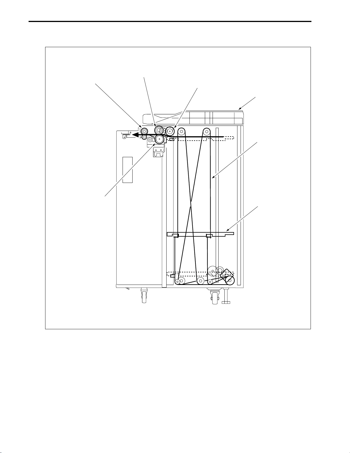
CENTER CROSS-SECTIONAL DRAWING
Feed roller
Conveyance roller
Paper feed roller
Top cover
Up/down wire
(the other side
wire as well)
Double feed
prevention roller
Up/down plate
1-2
Page 13

DRIVE SYSTEM DRAW I NG
[1] Paper feed drive section
LT First paper feed SD
(SD100)
LT-402/LT-412
Feed roller
Paper feed roller
FRONT
Conveyance roller
LT paper feed motor
(M101)
LT First paper feed MC
(MC 102)
LT feed drive MC
(MC101)
1-4
FRONT
Double feed
prevention roller
Feed roller
1-3
Paper feed roller
Page 14

LT-402/LT-412
[2] Stack ed paper up/down wire dri ve sec tion
a. LT-402
Up/down plate
FRONT
LT up/down motor
(M100)
Up/down shaft
1-4
Page 15

b. LT-412
LT-402/LT-412
Up/down plate
FRONT
LT up/down motor
(M100)
Up/down shaft
1-5
Page 16

Blank page
Page 17

2
UNIT EXPLANATION
Page 18

Blank page
Page 19

PAPER FEED SECTION
[1] Composition
LT feed MC (MC101)
LT paper
feed motor
(M101)
LT first paper feed MC (MC102)
LT first paper feed SD
(SD100)
Paper dust
removing brush
Conveyance
roller
LT-402/LT-412
LT feed PS (PS106)
LT first paper
feed PS (PS107)
Up/down wire
(the other side wire as well)
LT up/down motor
(M100)
Remaining paper detection gear
[2] Mechanisms
Mechanism Method
Paper lifting *1 Wire drive
Paper feed Paper feed roller
No paper detection
Remaining paper
detection *2
Paper conveyance Roller conveyance
*1 Pape r l ifting
a.Up/down plate lifting drive operation
The up/down plate is lifted with the up/down
wires. When the top cover closes, LT up/down
motor (M100) rotates and the up/down plate connected to the up/down wires rises.
b.Up/down plate down drive operation
The up/down plate autom atically lowers by 120
mm when the top cover is opened.
Subsequently , it is lowered by 120 mm each time
LT tray down drive switch (SW100) is pressed.
Photo sensor (PS108)
+actuator
Remaining paper detection gear+ photo sensor
(PS102, PS103, PS104,
PS105)
Up/down plate
LT tray down drive switch (SW 100)
*2 Re m ainin g paper det ection
The LCT is equipped with a remaining paper
detection gear which rotates together with L T up/
down motor (M100) driving the up/down plate.
The remaining paper detection gear has an actuator to turn ON/OFF LT remaining paper detection PS1 (PS102), L T remaining paper detection
PS2 (PS103), L T remaining paper detection PS3
(PS104), and L T remaining paper detection PS4
(PS105).
2-1
Page 20

LT-402/LT-412
Each sensor is turned ON/OFF according to the
rotating position of the remaining paper detection gear and since this is linked with the up/down
position of the up/down plate, the remaining
paper quantity in the LCT can be determined by
monitoring the ON/OFF of each sensor. The
remaining paper quantity detected with the four
sensors is displayed on the main body display.
a. LT-402
LT remaining paper
LT up/down motor (M100)
detection PS1
(PS102)
Actuator
LT remaining
paper detection
PS2 (PS103)
LT remaining
paper detection
PS3 (PS104)
Gear for M100
Remaining
LT remaining paper
detection PS4 (PS105)
paper detection
gear
b. LT-412
LT remaining
paper detection
PS2 (PS103)
LT remaining paper
detection PS1 (PS102)
LT remaining paper
detection PS3 (PS104)
[3] First paper feed control
UPOP_PS
S_GND
CONV_PS
S_GND
PR_PS
SIDOP_PS
24V
CONT
24V
CONT
24V
CONT
5V
5V
LT DB
HTR101
MAIN BODY
24V
PGND
5V
SGND
IO_DTXD
IO_UCLK
LCT_LATCH
IO_DCLK
ERR_OUT4
IO_URXD
ACK4
REQ4
The first paper is fed by the paper feed roller and
the feed roller driven by M101(LT paper feed) via
MC101(LT feed MC). The paper feed roller and
feed roller touche the paper when SD100 (L T first
feed) is ON, feeding the paper to the conveyance
roller. Then, SD100 (LT first paper feed) turns
OFF to release the paper feed roller and feed
roller from the paper. The conveyance roller is
also driven by M101, by turning ON MC102 (LT
first feed MC), paper is fed to the main body.
The related signals are: PS100 (LT top cover
open/close detection), PS106 (LT feed), PS107
(LT first feed), and PS110 (LT jam access door
open/close detection).
PS100
PS106
PS107
PS110
MC101
MC102
SD100
Actuator
Remaining paper
detection gear
Gear for M100
LT remaining paper
detection PS4 (PS105)
2-2
Page 21

LT-402/LT-412
1. Operation
a. First paper feed timing
(1) Start of first pa per feed
At predefined interval after the START button is
pressed.
(2) Start of se cond a nd subsequent papers
When PS106 (L T feed) is turned OFF by the preceding paper.
(3) OFF timing
When the main body M7 (paper exit) turns OFF.
b. Interlock
The power supply line of M101 (L T paper feed) is
equipped with MS101 (LT interlock/1) and
MS102 (LT interlock/2). When the top cover is
opened, MS101 turns OFF, and when the jam
access door is opened MS102 turns OFF,
thereby cutting off the power supply to M101.
Furthermore, the top cover is equipped with
PS100 (LT top cover open/close detection) and
the jam access door is equipped with PS110 (L T
jam access door open/close detection) and
when either of these doors is opened during
paper feed, the M101 drive signal is turned OFF
to stop the paper feed operation.
c. Internal heater
The LCT is equipped with HTR101 (LT internal
heater) to protect the paper from humidity.
HTR101 is directly controlled by the main body
PRCB (printer control board) rather than by the
LTDB (LT drive board).
2. Signals
a. Input signal s
(1) UPOP_PS (PS100 to LTDB)
Top c over open /clos e detection signal
[L]: Cover opened
[H]: Cover closed
(2) CONV_PS (PS106 to LTDB)
Conveyance roller ex it paper detection signal
[L]: Paper detected
[H]: Paper not detected
(3) PR_PS (PS107 to LTDB)
Conveyance roller entrance (pre-registration
position) paper detection signal
[L]: Paper detected
[H]: Paper not detected
(4) SIDOP_PS (PS110 to LTDB)
Jam access door open/close detection signal
[L]: Door opened
[H]: Door closed
(5) LCTM_EM (M101 to LTDB)
M101 rotation error detection signal
[L]: M101 rotating
[H]: M101 not rotating
(6) IO_DTXD (MAIN BODY to LTDB)
Serial data to tra nsmi t mai n body PRCB (printer
control board) operating status to LT DB
(7) LCT_LATCH (MAIN BO DY to LTDB)
IO_DTXD signal latch signal
(8) IO_DCLK (MAIN BODY to LTDB)
IO_DTXD signal clock signal
(9) ERR_OUT4 (MAIN BODY to LTDB)
Signal to notify LT DB (L T drive board) when there
is error in the main body
(10) ACK4 (M AIN BO DY to LTDB )
Serial data transmission enable signal from LCT
to main body PRCB (printer control board)
2-3
Page 22

LT-402/LT-412
b. O ut put sign als
(1) CONT (LTDB to MC101)
MC101 (LT feed MC) ON/OFF drive signal
[L]: MC101 ON
[H]: MC101 O FF
(2) CONT (LTDB to MC102)
MC102 (LT first paper feed MC) ON/OFF drive
signal
[L]: MC102 ON
[H]: MC102 O FF
(3) CONT (LTDB to SD100)
SD100 ( L T first paper feed) ON/OFF drive signal
[L]: SD100 ON
[H]: SD100 O FF
(4) LCTM_CONT (LTDB to M101)
M101 (LT p aper feed) ON/OFF control signal
[L]: M101 ON
[H]: M101 OFF
(5) IO_URXD (LTDB to MAIN BODY)
Serial data to transmit th e LTDB ( LT drive board)
operating status to main body PRCB
(6) IO_UCLK ( LTDB to MAIN BODY)
IO_URXD signal clock signal
(7) REQ 4 (LTDB to MAIN B ODY)
Serial data send request signal from LCT to main
body PRCB
(8) LCTM_CLK (M101 to LT DB)
M101 (LT paper feed) rotational speed control
clock signal
(9) LCTM_F/R (M101 to LTDB)
M101 (L T paper f eed) rotational direction indication signal
This machine always indicates [H]: normal rotation.
[4] Up/down plate drive control
LT DB
MAIN BODY
24V
PGND
SGND
IO_DTXD
IO_UCLK
LCT_LATCH
IO_DCLK
ERR_OUT4
IO_URXD
ACK4
REQ4
5V
When the top cover opens or closes, M100 (LT
up/down motor) rotates forward or backward to
move the up/down plate up or down. The up/
down plate descends by 120 mm each time
SW100 (L T tr a y down drive) is press ed while the
top cover is opened.
The related signals are PS100 (LT top cover
open/close detection), PS101 (LT lower limit
detection), and PS109 (L T upper limit detection).
1. Operation
a. Up/down plate descend timing
(1) ON timing
When the top cover is opened and PS100 (LT top
cover open/close detection) is turned OFF , M100
rotates backward to lower the up/down plate.
When SW100 (LT tray down drive) turns ON by
pressing, M100 rotates backward to move the
up/down plate down.
(2) OFF timing
M100 turns OFF at predefined interval after
PS100 turns O FF or SW1 00 tur ns ON . This in
turn lowers the up/down plate by 120 mm.
(3) Others
The up/down plate descends by 120 mm eac h
time SW100 is pressed until PS101 tur ns ON to
indicate the bo tto m limi t of the up/do wn plate.
UPOP_PS
S_GND
SIG
S_GND
DW_SW
UP_PS
S_GND
5V
5V
5V
D1
D2
PS100
PS101
SW100
PS109
M100
2-4
Page 23

LT-402/LT-412
b. Up/down plate ascend timing
(1) ON timing
When the top cover is closed and PS100 (L T top
cover open/close detection) is turned ON, M100
(LT UP/DOWN) rotates forward to raise the up/
down plate.
(2) OFF timing
When the up/down plate r ises and PS109 (LT
upper limit detection) turns ON to indi cate the
detection of the topmost paper, M100 (LT UP/
DOWN) turns OFF and stops the up/down plate.
The up/down plate also stops when the top cover
is opened and PS100 (LT top cov er open/ close
detection) turns OFF.
2. Signals
a. Input signals
(1) SIG (PS101 to LTDB)
Up/down plate lower limit detection signal
[L]: Up/down plate not at lower limit
[H]: Up/down plate at lower limit
(2) UP_PS (PS109 to LTDB)
Up/down plate uppe r limit detection signal
[L]: Up/down plate not at upper limit
[H]: Up/down plate at upper limit
(3) DW_SW (SW100 to LTDB)
SW100 (L T tr ay down switc h) ON/OFF detection
signal
[L]: SW100 ON
[H]: SW100 OFF
b. Output signal
(1) D1, 2 (LTDB to M100)
M100 (LT UP/DOWN) drive signal
These signals switches the direction of the drive
current to control the rotation direction of M100.
[5] Remaining paper det ection/ No paper
detection control
LT DB
MAIN BODY
24V
PGND
SGND
IO_DTXD
IO_UCLK
LCT_LATCH
IO_DCLK
ERR_OUT4
IO_URXD
ACK4
REQ4
5V
The remaining paper quantity is detected by
PS102 (LT remaining paper detection 1), PS103
(LT remaining paper detection 2), PS104 (LT
remaining paper detection 3), and PS105 (LT
remaining paper detection 4) and no paper
detection is made by PS108 (L T no paper detection).
The signals d etected by thes e sensors are controlled by L TDB (L T drive board) and displayed on
the main body display.
1. Operation
a. Remai ning paper dete ction c ontrol
The remaining paper quantity is determined from
the ON/OFF combination of sensors PS102 (LT
remaining paper detection 1), PS103 (L T remaining paper detection 2), PS104 (LT remaining
paper detection 3), and PS105 (LT remaining
paper detection 4) which detect the rotational
position of M100 (LT UP/DOWN) that is driving
the up/down plate. Each sensor turns ON or
OFF according to the pos ition of the remaining
paper detection gear which is linked with the
rotation of M100.
The remaining paper quantity is detectable at
eight levels, but it is displayed on the main body
display as five levels.
SIG
S_GND
SIG
S_GND
SIG
S_GND
SIG
S_GND
0_PS
S_GND
5V
5V
5V
5V
5V
D1
D2
PS102
PS103
PS104
PS105
PS108
M100
2-5
Page 24

LT-402/LT-412
<Remaining paper quantity and display>
Stacked
paper
quantity
0 to 700 OFF OFF OFF OFF 1 flashing
701 to 1200 ON OFF OFF OFF 1 on
1201 to 1700 ON ON OFF OFF 2 on
1701 to 2200 ON ON ON OFF 2 on
2201 to 2700 ON ON ON ON 3 on
2701 to 3200 OFF ON ON ON 3 on
3201 to 3700 OFF OFF ON ON 4 on
3701 or more OFF OFF OFF ON 4 on
Caution:
b. No paper detection control
When there is no more paper inside the LCT,
PS108 (LT no paper detection) turns O N an d a
message is displayed on the main body display.
PS102 PS103 PS104 PS105
The remaining paper quantity is indicated on
the control panel with four horizontal bars.
Stacked paper quantity differs depending on
the thickness of the paper.
Remaining
paper quantity
display
2. S ignals
a. Input signals
(1) SIG (PS102 to LTDB)
Remaining paper detection gear rotational position detection signal
[L]: PS102 OFF
[H]: PS102 ON
(2) SIG (PS103 to LTDB)
Remaining paper detection gear rotational position detection signal
[L]: PS103 OFF
[H]: PS103 ON
(3) SIG (PS104 to LTDB)
Remaining paper detection gear rotational position detection signal
[L]: PS104 OFF
[H]: PS104 ON
(4) SIG (PS105 to LTDB)
Remaining paper detection gear rotational position detection signal
[L]: PS105 OFF
[H]: PS105 ON
(5) 0_PS (PS108 to LTDB)
LCT no paper d etection signal
[L]: No paper
[H]: Paper present
2-6
Page 25

3
DISASSEMBLY/ASSEMBLY
Page 26

This section explains how to disassemble and reassemble the machine.
When disassembling and reassembling the machine, follow the precautions given below.
1. Be sure the power cord has been unplugged from the wall outlet.
2. Th e disassembled parts must be reas sembled following the disassembly procedure in reverse unless otherwise specified.
3. Care s hould be taken not to lo se small par ts. Care should also be
taken not to install small parts in wrong places.
4. Do not operate the machine before inst alling all the disassembled
parts completely.
5. Rem oval of some screws is prohibited in this section. Never loosen
them.
Page 27

PAPER FEED SECTION
LT-402/LT-412
[1] Cleaning the P aper Dust Rem oving
Brush
Caution:If LT is connected to the main
body , make sure that main body
power plug is disconnected
from the power outlet.
a. Procedure
(1) Open the top cover.
(2) Remove six screws to detach the paper feed
cover B.
Top
cover
Screws
Screws
[2] Cleaning the LT feed PS (PS 106)/LT
first pap er fe ed PS (PS 107)
Caution:If LT is connected to the main
body , make sure that main body
power plug is disconnected
from the power outlet.
a. Procedure
(1) Looking into the paper exit side of the LCT from
below, and clean sensors through the cavity for
LT feed PS (PS106) and the cavity for LT first
paper feed (PS107) using a blower brush.
Cavity for PS106
Cavity for PS107
Paper
exit
side
Paper feed cover B
(3) Insert a flat bladed screwdriver in the cavities (in
two locations) for paper dust removing brush to
release the locking lugs, then remove the paper
dust removing brush.
Paper dust removing brush
Cavity
Locking lugs
(4) Clean the paper dust removing brush using a
blower brush.
(5) Reinstall the above part s following the removal
steps in reverse.
3-1
Page 28

LT-402/LT-412
[3] Removing a nd Reinstalling the P aper
Feed Roller Unit
Caution: If LT is connected to the main
body , make sure that main body
power plug is disconnected
from the power outlet.
a. Procedure
(1) Open the top cover.
(2) Remove the spring from the paper feed roller
unit.
Top cover
Spring
Remove
this.
Paper feed roller unit
[4] Replacing the P aper Feed Roller Rub -
ber/Feed R olle r Rubb er
Caution:If LT is connected to the main
body , make sure that main body
power plug is disconnected
from the power outlet.
a. Procedure
(1) Remove the paper feed roller unit.
(2) Remove the bearing an d paper feed reference
actuator.
Paper feed reference actuator
Paper feed roller unit
(3) A fter removing two stop rings, remove the two
bearings outward to remove the paper feed roller
unit.
Paper feed roller unit
Bearing
Stop ring
Bearing
Stop ring
Bearing
(3) Remove two stop rings.
(4) Remove two bearings outward to detach the
roller section from the roller fitting.
Roller fitting
Stop rings
Bearing
Bearing
(4) Rei nstall the above parts following the removal
steps in reverse.
3-2
Page 29

LT-402/LT-412
(5) Remove the bearing from the opposite side of the
coupling, then remove the paper feed roller from
the shaft.
(6) Remove the stop ring to pull the feed roller from
the shaft.
(7) Remove the rubber from each roller.
Coupling
Feed roller
Paint mark
Paper feed
roller
Bearing
Paper feed roller rubber
Shaft
Shaft
Stop ring
Feed roller rubber
[5] Replacing the Double Feed Preven-
tion Roller Rub ber
Caution:If LT is connected to the main
body , make sure that main body
power plug is disconnected
from the power outlet.
a. Procedure
Caution:
(1) Remove the paper feed roller unit.
(2) Remove two screws to detach the double feed
prevention roller unit cover.
With the power held on, press the LT
tray down s witch (SW100) to move the
up/down plate down to the bottom in
advance.
Double feed
Double feed
prevention roller
prevention roller unit cover
(8) Reinstall the above part s following the removal
steps in reverse.
Caution1:
Make sure rollers and rubber portions are oriented properly when
reinstalling them.
Caution2:
Make sure the one-way clutch direction is correct.
Caution3:
Check whether grease or the like is
present on each roller.
Screws
3-3
Page 30

LT-402/LT-412
(3) Rem ove two screws to detach the double feed
prevention roller unit.
Caution:
When reinstalling the double feed prevention roller unit, tighten the screws
on the rear side first.
Double feed prevention roller unit
Screws
(4) Remove two stop rings, fit the shaft into the D-cut
in the fitting, and remove the double feed prevention roller together with the shaft.
Double feed prevention roller
D-cut
(5) Remove the double feed prev ention roller rubber
from the double feed prevention roller.
Paint mark
Double feed
prevention roller
Shaft
Double feed
prevention roller
rubber
(6) Reinstall the double feed prevention roller in the
reverse order of the removal procedure.
Caution1:
Make sure the double feed prevention roller rubber is oriented properly
when reinstalling it.
Caution2:
Check whether scratch or the like is
visible on the pet cover for the drive
gear.
Caution3:
Check whether grease or the like is
present on double feed prevention
roller.
Stop ring
3-4
Page 31

LT-402/LT-412
[6] Replacing the LT feed MC (MC101)/L T
first paper feed MC (MC102)
a. Procedure
(1) Open the top cover.
(2) Remove the spring from the paper feed roller
unit.
(3) Remove two screws to detach the top cover.
Top cover
Screws
(4) Remove three screws to detach the clutch
replacement cover.
(5) Disconnect two relay connectors (CN765,
CN766) of the clutches.
(6) Remove the stop ring to detach each clutch.
LT first paper feed MC (MC102)
LT feed MC (MC101)
Stop ring
Relay connector
(CN766)
Relay connector (CN765)
Stop ring
(7) Reinstall the above part s following the removal
steps in reverse.
Caution:
When installing each MC, make sure
that the stopper of each clutch is on
the predefined position.
Clutch
replacement cover
Screws
3-5
Page 32

LT-402/LT-412
[7] Replacing th e LT-402 Up/Down W ir es
Caution:
a. Procedure
(1) Open the top cover.
(2) Remove the clutch replacement cover.
(3) Remove five screws to detach the right side
cover.
With the power held o n, press the LT
tray down switch (SW100) to move the
up/down plate down to the bottom in
advance.
Screws
Right side
cover
Screws
(5) Remove twelve screws to detach the rear cover.
Screw
Screws
Screws
Screws
Rear cover
(6) Remove the five relay connectors (CN749,
CN780, CN781, CN782, CN783) to disconnect
the wiring harness from the up/down motor
mounting assembly.
(7) Remove the E-ring to detach the up/down gear.
(8) Pull the pin from the shaft.
(9) Remove the E-ring to detach the bearing.
(10) Remove three screws to detach the up/down
motor assembly.
(4) A fter opening the jam access door, remove six
screws to detach the front cover.
Caution:
When removing the front cover, close
the jam access door after removing
the screws.
Jam access door
Screws
Right side cover
Screws
Relay connector
Up/down
motor mounting
assembly
Shaft
(CN749)
Screw
Pin
Screw
Bearing
E-ring
Relay
connector
(CN780)
Relay
connector
(CN781)
Relay
connector
(CN782)
Relay
connector
(CN783)
Screw
Up/down
gear
E-ring
3-6
Page 33

(11) Replace the up/down wire following the instruc-
tions in “Removing Up/Down Wires’’ and “Installing Up/Down Wires.’’
LT-402/LT-412
Caution:
Wire A
Wire B
Wire C
Wire D
Two sets of four up/down wires with
different length, one set at the front
and the other at the back, are used.
Wires with the same length can be
used either at the front or back if they
are used in the same location.
1323.6mm
1250.3mm
769.3mm
661mm
3-7
Page 34

LT-402/LT-412
<Removing the Up/Down Wires>
Wire A
Wire B
Wire B
Wire A
Up/down plate
2. Release the metal
ball to remove wire
C.
18.Release the metal
ball to remove wire
A.
4. Release the metal
ball to remove wire
D.
14.Release the metal
ball to remove wire
A.
7. Release the metal
ball to remove wire
C.
9. Release the metal
ball to remove wire
D.
12.Release the metal
ball to remove wire
B.
Wire C
Wire D
6. Remove the E-ring.
8. Remove the pulley.
10.Remove the pulley.
FRONT
Up/down
shaft
16.Release the metal
ball to remove wire
B.
Wire D
Wire C
1. Remove the E-ring.
3. Remove the pulley.
5. Remove the pulley.
15.Remove the Ering, then remove
the pulley to
release wire B.
11.Remove the E-ring,
then remove the
pulley to release
wire B.
13.Remove the pulley to
release wire A.
3-8
17.Remove the pulley
to release wire A.
Page 35

<Installing the Up/Down Wires>
LT-402/LT-412
Wire A
Wire B
7. Insert wire A in the
pulleys, then attach a
metal ball.
15.Insert wire C in the
pulleys, then attach a
metal ball.
12.Insert wire D in the
pulleys, then attach a
metal ball.
10.Insert wire B in the
pulleys, then attach a
metal ball.
Wire C
Wire D
13.Insert wire C in the up/
down shaft, attach a
pulley, and secure the
pulley with an E-ring.
14.Wind wire C around
the pulley by 6 turns in
such a manner that the
wire can be pulled
from over the pulley.
Wire B
Wire A
FRONT
Up/down plate
1. Insert wire A in
6. the up/down
shaft, attach
pulleys, then
pull the wire
from under the
pulleys.
Up/down
shaft
20.Insert wire B in the pulleys,
then attach a metal ball.
2. Insert wire A in the pulleys,
then attach a metal ball.
17.Insert wire D in the pulleys,
then attach a metal ball.
5. Insert wire B in the pulleys,
then attach a metal ball.
Wire D
Wire C
18.Insert wire C in the up/
down shaft, attach a
pulley, and secure the
pulley with an E-ring.
19.Wind wire C around
the pulley by 6 turns
in such a manner that
the wire can be pulled
from over the pulley.
6 turns
6 turns
11.Insert wire D in the up/
down shaft, attach a
pulley, and wind wire
D around the pulley by
six turns in such a
manner that the wire
can be pulled from
over the pulley.
6 turns
3. Insert wire B in the up/
8. down shaft, attach a
pulley, and secure the
pulley with E-rings.
4. Pull wire B from under the
9. pulleys.
3-9
16.Insert wire D in the up/
down shaft, attach a
pulley, and wind wire
D around the pulley by
six turns in such a
manner that the wire
can be pulled from
over the pulley.
6 turns
Page 36

LT-402/LT-412
(12)After installing the up/down wires, make s ure the
up/down wires are passe d in the grooves in the
pulleys properly and wires do not run on the
sides of the pulleys. Also make sure the up/down
plate can be m oved up and down smoothly by
hand.
Caution: If the up/down plate does not move up
and down smoothly, reinstall the up/
down wires.
(13)Ins tall the up/down wire drive motor assembly,
up/down gear, and relay connectors, following
the removal steps in reverse.
(14) R emove th e E -ring to d etach the idle gear.
(15)Rotat e the remaining paper detection gear until
the round hole in this gea r is aligned with the
oblong hole in the up/down motor mounting
assembly.
Caution: Align when the up/down plate is in low-
est position.
Up/down motor
mounting assembly
Remaining paper
detection gear
[8] Replacing the LT - 412 Up/Dow n Wires
a. Procedure
Caution: With the power held on, press the LT
tray down switch (SW100) to move the
up/down plate down to the bottom in
advance.
(1) Remove the clutch replacement cover, side
cover (right), front cover , and rear cover f ollowing
the steps (1) to (5) in [7] Replacing the LT-402
Up/Down Wires.
(2) Remove the E-ring.
(3) Remove the five screws to detach the gear cover .
(4) Remove the two bearings.
Screw
Screw
E-ring
Screws
Bearing
Gear cover
Bearing
Round
hole
Idle gear
E-ring
Oblong
hole
(16)I ns tall the idle gear.
(17)A ttach the covers following the removal steps in
reverse.
Caution1: After replacing the up/down wires,
make horizontal and centering
adjustment of the up/down plate.
(Refer to “ADJUSTMENT SECTION.”)
(5) Remove the gear A.
(6) Remove the E-ring to remove gear B.
(7) Remove the detent pin for gear B from the up/
down pulley shaft.
(8) Remove the E-ring and bearing to remove gear
C.
Gear A
Pin
Gear B
Bearing
Up/down pulley shaft
Gear C
E-ring
E-ring
3-10
Page 37

LT-402/LT-412
g
(9) Remove the bearing behind gear C.
(10) Remove the E-ring to remove the up/down gear.
(11) Remove the detent pin for up/down gear from the
up/down pulley shaft.
(12) Remove the E-ring to remove gear D.
(13) Remove the E-ring to remove the remaining
paper detection gear.
(14)Remove four relay connectors (CN780, CN781,
CN782, and CN783) to disconnect the wiring
harness from the up/down motor mounting
assembly.
Relay connector
(CN780)
Remaining paper
detection gear
Gear D
E-ring
Relay
connector
(CN781)
Relay connector
(CN782)
Up/down
motor mounting
assembly
(17) Replace the up/down wires following the instruc-
tions in “Removing the Up/Down Wires” and
“Installing Up/Down Wires.”
Caution: Two sets of four up/down wires with
different length, one set at the front
and the other at the back, are used.
Wires with the same length can be
used either at the front or back if they
are used in the same location.
1057.3mm
Wire A
692.1mm
Wire B
1321.7mm
Wire C
1303.1mm
Wire D
Pin
Up/down
gear
E-ring
Up/down pulley shaft
Bearing
Relay
connector
(CN783)
E-ring
(15) Remove the E-ring to remove the bearing.
(16) Remove the six screws to remove the up/down
motor mounting assembly.
Up/down motor mounting assembly
Screws
Bearing
E-rin
Screws
3-11
Page 38

LT-402/LT-412
<Removing the Up/Down Wires>
Wire C
Wire D
14.Release the metal
ball to remove wire
D.
7. Release the metal
ball to remove wire
A.
9. Release the metal
ball to remove wire
B.
12.Release the metal
ball to remove wire
C.
Wire C
Wire D
Up/down plate
2. Release the metal
ball to remove wire
A.
18.Release the metal
ball to remove wire
D.
4. Release the metal
ball to remove wire
B.
16.Release the metal
ball to remove wire
C.
Wire B
Wire A
1. Remove the E-ring.
3. Remove the pulley.
Wire A
6. Remove the E-ring.
8. Remove the pulley.
10.Remove the pulley.
Wire B
FRONT
11.Remove the E-ring,
then remove the
pulley to release
wire C.
Up/down shaft
13.Remove the pulley to
release wire D.
5. Remove the pulley.
15.Remove the E-ring,
then remove the
pulley to release
wire C.
17.Remove the pulley
to release wire D.
3-12
Page 39

<Installing the Up/Down Wires>
LT-402/LT-412
Wire C
Wire D
Wire C
Wire D
7. Insert wire D in the
pulleys, then attach a
metal ball.
15.Insert wire A in the
pulleys, then attach a
metal ball.
12.Insert wire B in the
pulleys, then attach a
metal ball.
10.Insert wire C in the
pulleys, then attach a
metal ball.
Wire A
Wire B
13.Insert wire A in the up/down
shaft, attach a pulley, and
secure the pulley with an E-ring.
14.Wind wire A around the pulley
by 6 turns in such a manner
that the wire can be pulled
from over the pulley.
6 turns
11.Insert wire B in the up/down shaft,
attach a pulley, and wind wire B
around the pulley by six turns in
such a manner that the wire can
be pulled from over the pulley.
Up/down plate
FRONT
3. Insert wire C in the up/down
8. shaft, attach a pulley, and
4. Pull wire C from under the
9. pulleys.
Up/down
shaft
1. Insert wire D in the
6. up/down shaft, attach
pulleys, then pull wire
D from under the
pulleys.
secure the pulley with E-rings.
20.Insert wire A in the
pulleys, then attach a
metal ball.
2. Insert wire D in the
pulleys, then attach a
metal ball.
17.Insert wire B in the
pulleys, then attach a
metal ball.
5. Insert wire C in the
pulleys, then attach a
metal ball.
Wire B
Wire A
18.Insert wire A in the up/
down shaft, attach a
pulley, and secure the
pulley with an E-ring.
19.Wind wire A around the
pulley by 6 turns in such
a manner that the wire
can be pulled from over
the pulley.
6 turns
16.Insert wire B in the up/
down shaft, attach a
pulley, and wind wire B
around the pulley by six
turns in such a manner
that the wire can be
pulled from over the
pulley.
6 turns
6 turns
3-13
Page 40

LT-402/LT-412
(18) After installing the up/down wires, check whether
they are engaged with the pulleys proper ly and
whether they do not ride over the pulleys. Next,
move the up/down plate manually to check
whether it moves up and down smoothly.
Caution: If the up/down plate does not move
smoothly, remove the up/down wires
and install them again.
(19) Install the up/down motor mounting assembly,
relay connectors, remaining paper detection
gear, gear D, and up/down gear following the
removal steps in reverse.
(20)Rotat e the remaining paper detection gear until
the round hole in this gea r is aligned with the
oblong hole in the up/down motor mounting
assembly.
Up/down motor
mounting assembly
Remaining paper
detection gear
Oblong hole
Round hole
Caution: Align them when the up/down plate is
at the bottom.
(21)Install gear C.
(22)Attach the other gears, gear cover, and external
covers following the removal steps in reverse.
Caution: After replaci ng the up/down wires,
make horizontal and centering adjust-
ment of the up/down plate. (Refer to
“ADJUSTMENT SECTION.”)
3-14
 Loading...