

Page 1

Confidential – for internal use only, do not distribute
Page 2

THEORY OF OPERATION TOTAL CONTENTS
Confidential – for internal use only, do not distribute
SAFETY AND IMPORTANT WARNING ITEMS ..............................................................S-1
IMPORTANT NOTICE ................................................................................................S-1
DESCRIPTION ITEMS FOR DANGER, WARNING AND CAUTION .........................S-1
SAFETY WARNINGS .................................................................................................S-2
SAFETY INFORMATION ...............................................................................................S-12
IMPORTANT NOTICE ..............................................................................................S-12
INDICATION OF WARNING ON THE MACHINE .....................................................S-13
MEASURES TO TAKE IN CASE OF AN ACCIDENT ....................................................S-15
Composition of the service manual ................................................................................. C-1
Notation of the service manual ....................................................................................... C-2
bizhub 500/420/360 Main Body
OUTLINE ........................................................................................................................ 1
COMPOSITION/OPERATION ........................................................................................ 9
* For particulars, see the contents of the main body.
DF-607
OUTLINE ........................................................................................................................ 1
COMPOSITION/OPERATION ........................................................................................ 5
* For particulars, see the contents of DF-607.
PC-202
OUTLINE ........................................................................................................................ 1
COMPOSITION/OPERATION ........................................................................................ 3
* For particulars, see the contents of PC-202.
PC-402
OUTLINE ........................................................................................................................ 1
COMPOSITION/OPERATION ........................................................................................ 3
* For particulars, see the contents of PC-402.
LU-201
OUTLINE ........................................................................................................................ 1
COMPOSITION/OPERATION ........................................................................................ 3
* For particulars, see the contents of LU-201.
i
Page 3

FS-510/PU-501/OT-601
Confidential – for internal use only, do not distribute
OUTLINE ........................................................................................................................ 1
COMPOSITION/OPERATION........................................................................................ 9
* For particulars, see the contents of FS-510/PU-501/OT-601.
FS-511/RU-502
OUTLINE ........................................................................................................................ 1
COMPOSITION/OPERATION........................................................................................ 7
* For particulars, see the contents of FS-511/RU-502.
SD-502
OUTLINE ........................................................................................................................ 1
COMPOSITION/OPERATION........................................................................................ 3
* For particulars, see the contents of SD-502.
MT-501
OUTLINE ........................................................................................................................ 1
COMPOSITION/OPERATION........................................................................................ 3
* For particulars, see the contents of MT-501.
JS-502
OUTLINE ........................................................................................................................ 1
COMPOSITION/OPERATION........................................................................................ 3
* For particulars, see the contents of JS-502.
ii
Page 4
SAFETY AND IMPORTANT WARNING ITEMS
Confidential – for internal use only, do not distribute
SAFETY AND IMPORTANT WARNING ITEMS
Read carefully the Safety and Important Warning Items described below to understand
them before doing service work.
IMPORTANT NOTICE
Because of possible hazards to an inexperienced person servicing this product as well as
the risk of damage to the product, Konica Minolta Business Technologies, INC. (hereafter
called the KMBT) strongly recommends that all servicing be performed only by KMBTtrained service technicians.
Changes may have been made to this product to improve its performance after this Service
Manual was printed. Accordingly, KMBT does not warrant, either explicitly or implicitly, that
the information contained in this Service Manual is complete and accurate.
The user of this Service Manual must assume all risks of personal injury and/or damage to
the product while servicing the product for which this Service Manual is intended.
Therefore, this Service Manual must be carefully read before doing service work both in the
course of technical training and even after that, for performing maintenance and control of
the product properly.
Keep this Service Manual also for future service.
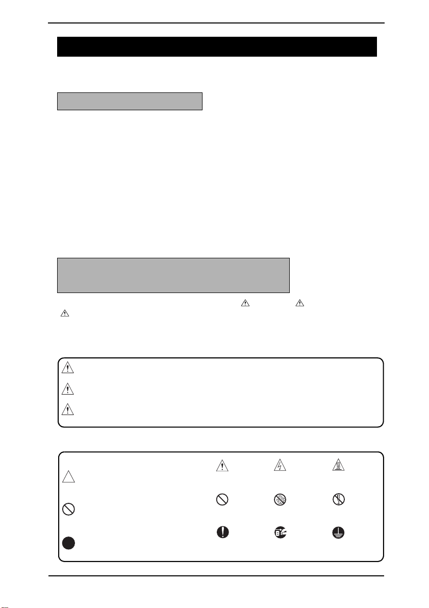
DESCRIPTION ITEMS FOR DANGER, WARNING AND CAUTION
In this Service Manual, each of three expressions " DANGER", " WARNING", and
" CAUTION" is defined as follows together with a symbol mark to be used in a limited
meaning.
When servicing the product, the relevant works (disassembling, reassembling, adjustment,
repair, maintenance, etc.) need to be conducted with utmost care.
DANGER: Action having a high possibility of suffering death or serious injury
WARNING: Action having a possibility of suffering death or serious injury
CAUTION: Action having a possibility of suffering a slight wound, medium
trouble and property damage
Symbols used for safety and important warning items are defined as follows:
:Precaution when using the
copier.
:Prohibition when using the
copier.
:Direction when using the
copier.
General
precaution
General
prohibition
General
instruction
Electric hazard High
Do not touch
with wet hand
Unplug Ground/Earth
temperature
Do not
disassemble
S-1
Page 5
SAFETY AND IMPORTANT WARNING ITEMS
Confidential – for internal use only, do not distribute
SAFETY WARNINGS
[1] MODIFICATIONS NOT AUTHORIZED BY KONICA MINOLTA
BUSINESS TECHNOLOGIES, INC.
Konica Minolta brand products are renowned for their high reliability. This reliability is
achieved through high-quality design and a solid service network.
Product design is a highly complicated and delicate process where numerous mechanical,
physical, and electrical aspects have to be taken into consideration, with the aim of arriving
at proper tolerances and safety factors. For this reason, unauthorized modifications involve
a high risk of degradation in performance and safety. Such modifications are therefore
strictly prohibited. The points listed below are not exhaustive, but they illustrate the reasoning behind this policy.
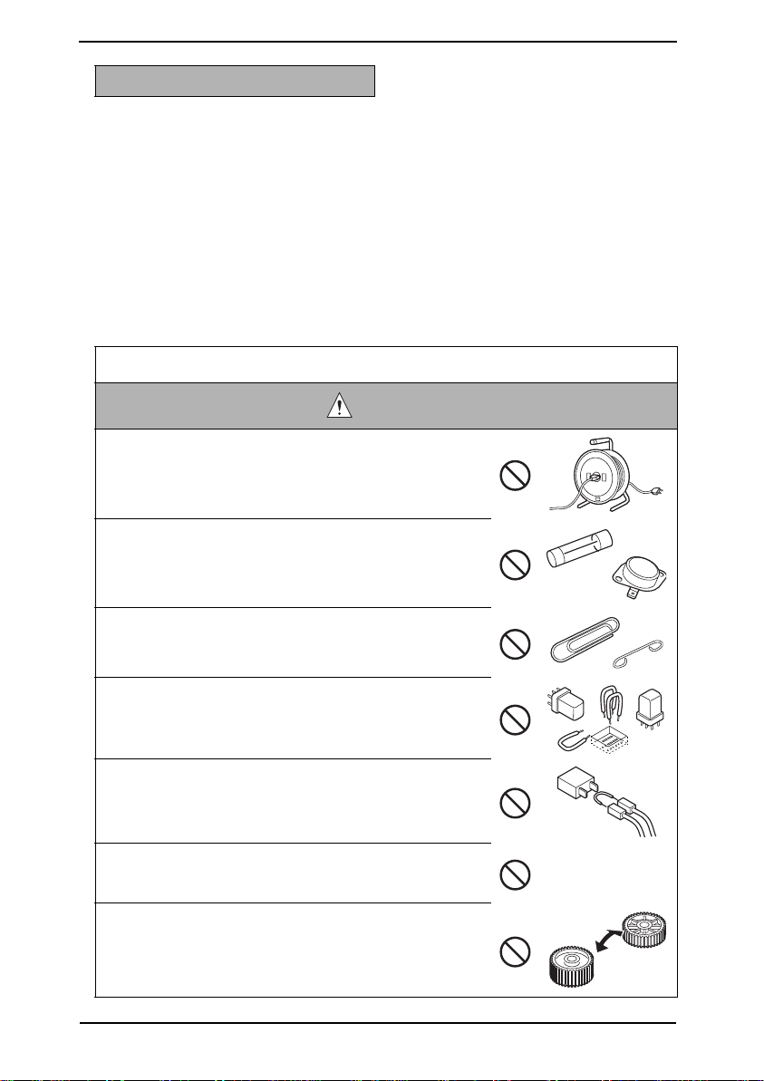
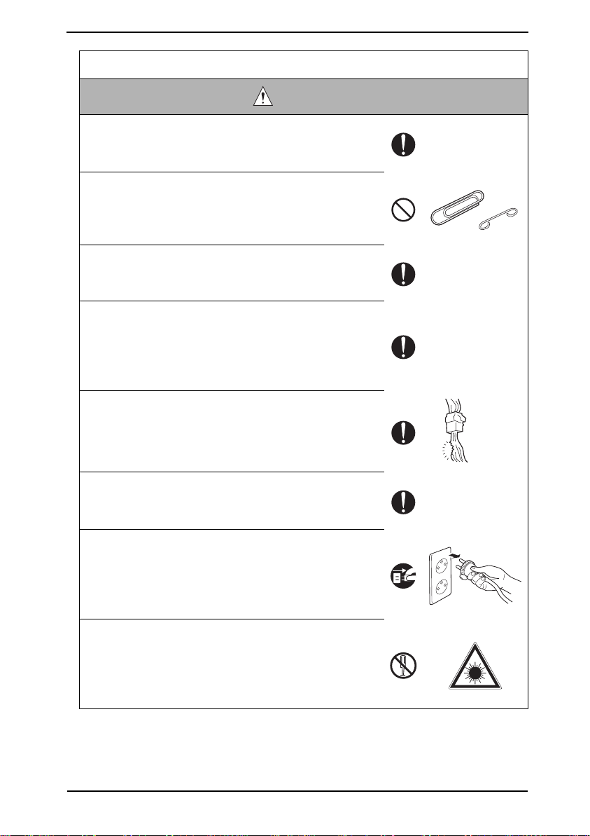
Prohibited Actions
DANGER
• Using any cables or power cord not specified by KMBT.
• Using any fuse or thermostat not specified by KMBT.
Safety will not be assured, leading to a risk of fire and
injury.
• Disabling fuse functions or bridging fuse terminals with
wire, metal clips, solder or similar object.
• Disabling relay functions (such as wedging paper between
relay contacts)
• Disabling safety functions (interlocks, safety circuits, etc.)
Safety will not be assured, leading to a risk of fire and
injury.
• Making any modification to the product unless instructed
by KMBT
• Using parts not specified by KMBT
S-2
Page 6
SAFETY AND IMPORTANT WARNING ITEMS
Confidential – for internal use only, do not distribute
[2] POWER PLUG SELECTION
In some countries or areas, the power plug provided with the product may not fit wall outlet
used in the area. In that case, it is obligation of customer engineer (hereafter called the CE)
to attach appropriate power plug or power cord set in order to connect the product to the
supply.
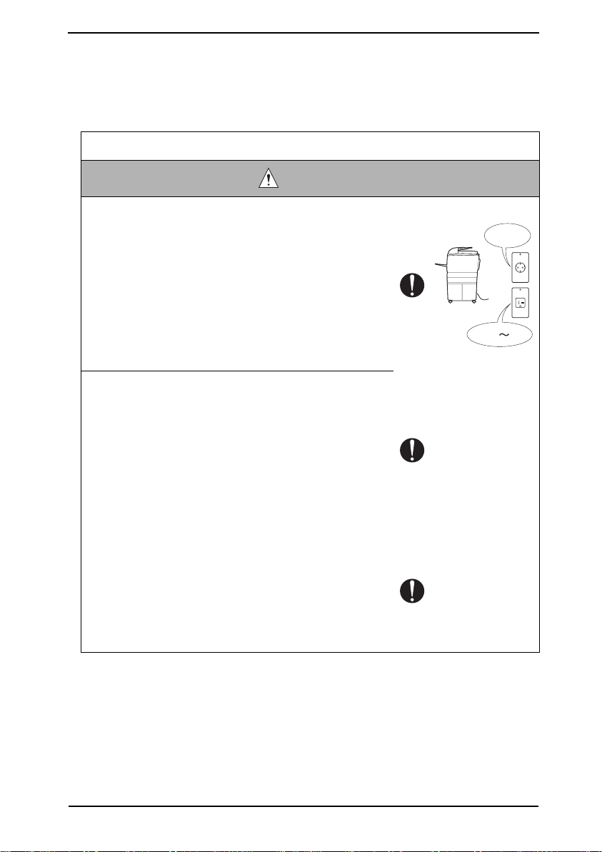
Power Cord Set or Power Plug
WARNING
• Use power supply cord set which meets the following
criteria:
- provided with a plug having configuration intended for
the connection to wall outlet appropriate for the product's rated voltage and current, and
- the plug has pin/terminal(s) for grounding, and
- provided with three-conductor cable having enough current capacity, and
- the cord set meets regulatory requirements for the area.
Use of inadequate cord set leads to fire or electric shock.
• Attach power plug which meets the following criteria:
- having configuration intended for the connection to wall
outlet appropriate for the product's rated voltage and
current, and
- the plug has pin/terminal(s) for grounding, and
- meets regulatory requirements for the area.
Use of inadequate cord set leads to the product connecting to inadequate power supply (voltage, current capacity, grounding), and may result in fire or electric shock.
• Conductors in the power cable must be connected to ter-
minals of the plug according to the following order:
• Black or Brown: L (line)
• White or Light Blue: N (neutral)
• Green/Yellow: PE (earth)
Wrong connection may cancel safeguards within the
product, and results in fire or electric shock.
AC230V
AC208V 240V
S-3
Page 7
SAFETY AND IMPORTANT WARNING ITEMS
Confidential – for internal use only, do not distribute
[3] CHECKPOINTS WHEN PERFORMING ON-SITE SERVICE
Konica Minolta brand products are extensively tested before shipping, to ensure that all
applicable safety standards are met, in order to protect the customer and CE from the risk
of injury. However, in daily use, any electrical equipment may be subject to parts wear and
eventual failure. In order to maintain safety and reliability, the CE must perform regular
safety checks.
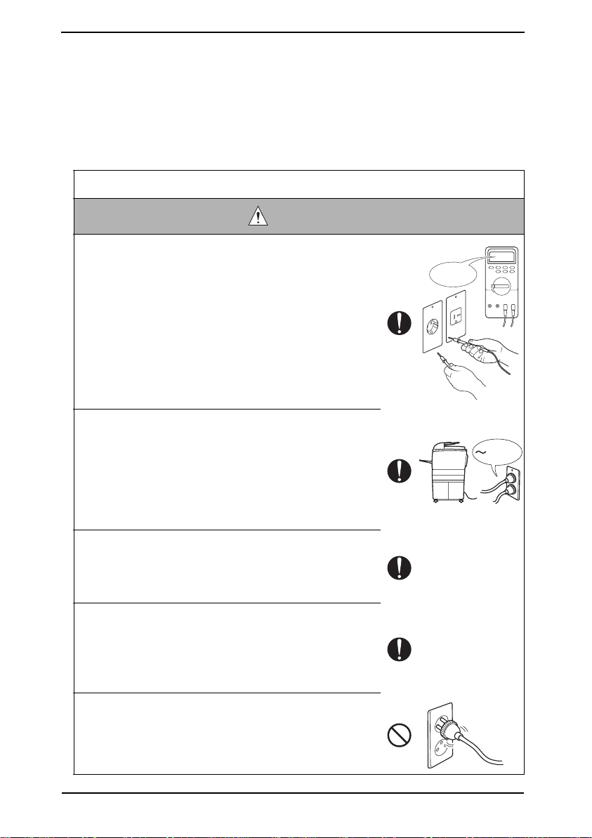
1. Power Supply
Connection to Power Supply
WARNING
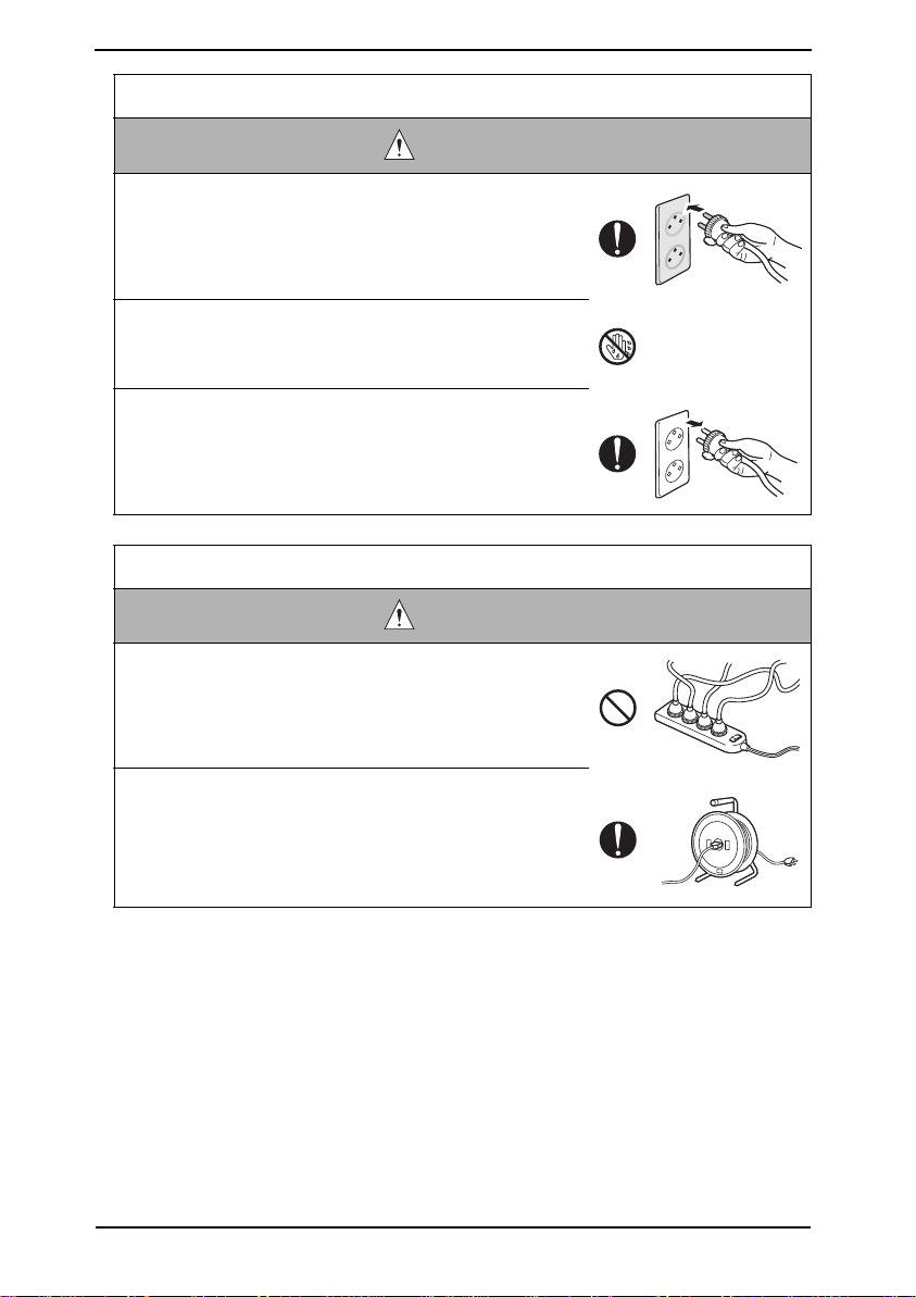
• Check that mains voltage is as specified.
Connection to wrong voltage supply may result in fire or
electric shock.
• Connect power plug directly into wall outlet having same
configuration as the plug.
Use of an adapter leads to the product connecting to
inadequate power supply (voltage, current capacity,
grounding), and may result in fire or electric shock.
If proper wall outlet is not available, advice the customer
to contact qualified electrician for the installation.
• Plug the power cord into the dedicated wall outlet with a
capacity greater than the maximum power consumption.
If excessive current flows in the wall outlet, fire may
result.
• If two or more power cords can be plugged into the wall
outlet, the total load must not exceed the rating of the wall
outlet.
If excessive current flows in the wall outlet, fire may
result.
• Make sure the power cord is plugged in the wall outlet
securely.
Contact problems may lead to increased resistance,
overheating, and the risk of fire.
? V
kw
S-4
Page 8
SAFETY AND IMPORTANT WARNING ITEMS
Confidential – for internal use only, do not distribute
Connection to Power Supply
WARNING
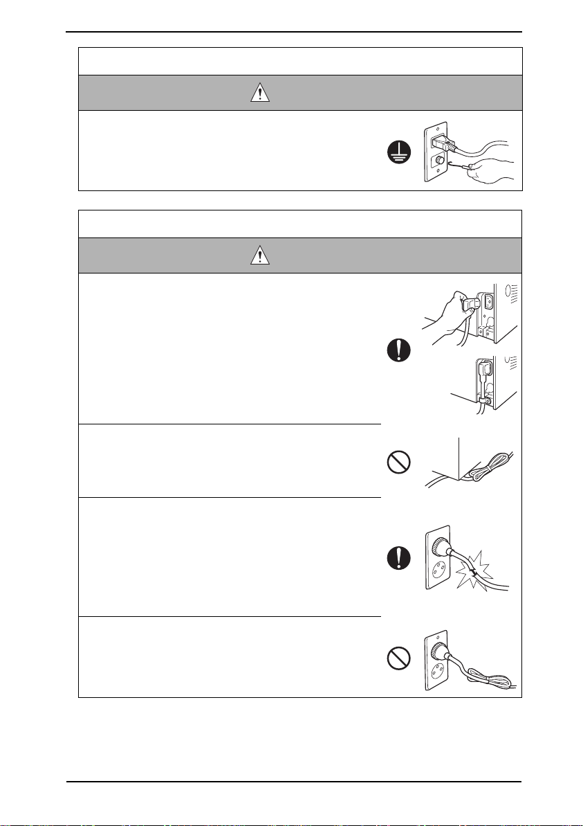
• Check whether the product is grounded properly.
If current leakage occurs in an ungrounded product, you
may suffer electric shock while operating the product.
Connect power plug to grounded wall outlet.
Power Plug and Cord
WARNING
• When using the power cord set (inlet type) that came with
this product, make sure the connector is securely inserted
in the inlet of the product.
When securing measure is provided, secure the cord with
the fixture properly.
If the power cord (inlet type) is not connected to the product securely, a contact problem may lead to increased
resistance, overheating, and risk of fire.
• Check whether the power cord is not stepped on or
pinched by a table and so on.
Overheating may occur there, leading to a risk of fire.
• Check whether the power cord is damaged. Check
whether the sheath is damaged.
If the power plug, cord, or sheath is damaged, replace
with a new power cord or cord set (with plug and connector on each end) specified by KMBT.
Using the damaged power cord may result in fire or electric shock.
• Do not bundle or tie the power cord.
Overheating may occur there, leading to a risk of fire.
S-5
Page 9
SAFETY AND IMPORTANT WARNING ITEMS
Confidential – for internal use only, do not distribute
Power Plug and Cord
WARNING
• Check whether dust is collected around the power plug
and wall outlet.
Using the power plug and wall outlet without removing
dust may result in fire.
• Do not insert the power plug into the wall outlet with a wet
hand.
The risk of electric shock exists.
• When unplugging the power cord, grasp the plug, not the
cable.
The cable may be broken, leading to a risk of fire and
electric shock.
Wiring
WARNING
• Never use multi-plug adapters to plug multiple power
cords in the same outlet.
If used, the risk of fire exists.
• When an extension cord is required, use a specified one.
Current that can flow in the extension cord is limited, so
using a too long extension cord may result in fire.
Do not use an extension cable reel with the cable taken
up. Fire may result.
S-6
Page 10
SAFETY AND IMPORTANT WARNING ITEMS
Confidential – for internal use only, do not distribute
2. Installation Requirements
Prohibited Installation Places
WARNING
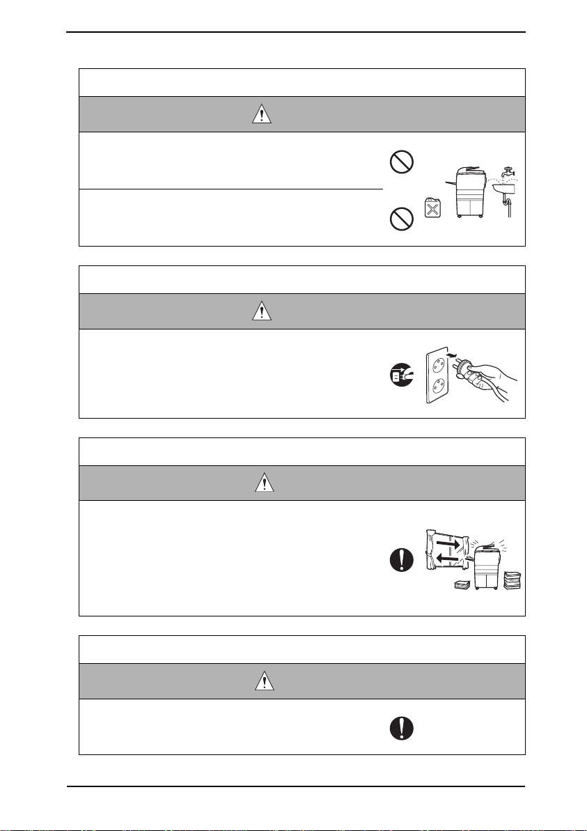
• Do not place the product near flammable materials or vol-
atile materials that may catch fire.
A risk of fire exists.
• Do not place the product in a place exposed to water such
as rain.
A risk of fire and electric shock exists.
When not Using the Product for a long time
WARNING
• When the product is not used over an extended period of
time (holidays, etc.), switch it off and unplug the power
cord.
Dust collected around the power plug and outlet may
cause fire.
Ventilation
• The product generates ozone gas during operation, but it
will not be harmful to the human body.
If a bad smell of ozone is present in the following cases,
ventilate the room.
a. When the product is used in a poorly ventilated room
b. When taking a lot of copies
c. When using multiple products at the same time
Fixing
• Be sure to lock the caster stoppers.
In the case of an earthquake and so on, the product may
slide, leading to a injury.
CAUTION
CAUTION
S-7
Page 11
SAFETY AND IMPORTANT WARNING ITEMS
Confidential – for internal use only, do not distribute
Inspection before Servicing
CAUTION
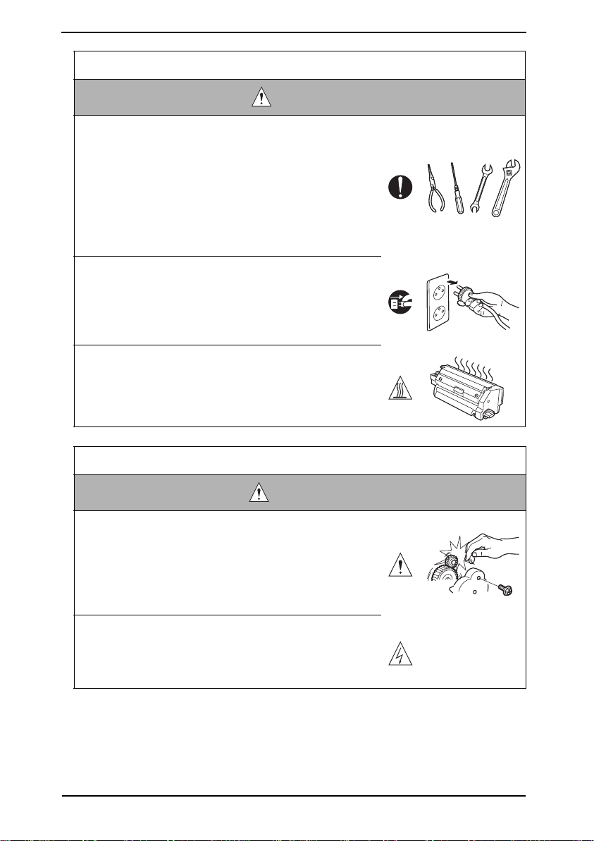
• Before conducting an inspection, read all relevant docu-
mentation (service manual, technical notices, etc.) and
proceed with the inspection following the prescribed pro-
cedure in safety clothes, using only the prescribed tools.
Do not make any adjustment not described in the docu-
mentation.
If the prescribed procedure or tool is not used, the product may break and a risk of injury or fire exists.
• Before conducting an inspection, be sure to disconnect
the power plugs from the product and options.
When the power plug is inserted in the wall outlet, some
units are still powered even if the POWER switch is
turned OFF. A risk of electric shock exists.
• The area around the fixing unit is hot.
You may get burnt.
Work Performed with the Product Powered On
• Take every care when making adjustments or performing
an operation check with the product powered.
If you make adjustments or perform an operation check
with the external cover detached, you may touch live or
high-voltage parts or you may be caught in moving gears
or the timing belt, leading to a risk of injury.
• Take every care when servicing with the external cover
detached.
High-voltage exists around the drum unit. A risk of electric shock exists.
S-8
WARNING
Page 12
SAFETY AND IMPORTANT WARNING ITEMS
Confidential – for internal use only, do not distribute
Safety Checkpoints
WARNING
• Check the exterior and frame for edges, burrs, and other
damages.
The user or CE may be injured.
• Do not allow any metal parts such as clips, staples, and
screws to fall into the product.
They can short internal circuits and cause electric shock
or fire.
• Check wiring for squeezing and any other damage.
Current can leak, leading to a risk of electric shock or
fire.
• Carefully remove all toner remnants and dust from electri-
cal parts and electrode units such as a charging corona
unit.
Current can leak, leading to a risk of product trouble or
fire.
• Check high-voltage cables and sheaths for any damage.
Current can leak, leading to a risk of electric shock or
fire.
• Check electrode units such as a charging corona unit for
deterioration and sign of leakage.
Current can leak, leading to a risk of trouble or fire.
• Before disassembling or adjusting the write unit (P/H unit)
incorporating a laser, make sure that the power cord has
been disconnected.
The laser light can enter your eye, leading to a risk of
loss of eyesight.
• Do not remove the cover of the write unit. Do not supply
power with the write unit shifted from the specified mount-
ing position.
The laser light can enter your eye, leading to a risk of
loss of eyesight.
S-9
Page 13
SAFETY AND IMPORTANT WARNING ITEMS
Confidential – for internal use only, do not distribute
Safety Checkpoints
WARNING
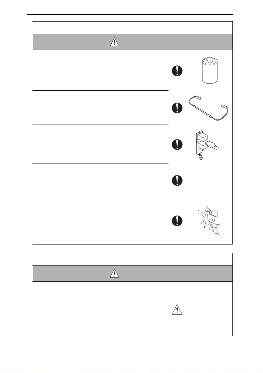
• When replacing a lithium battery, replace it with a new lith-
ium battery specified in the Parts Guide Manual. Dispose
of the used lithium battery using the method specified by
local authority.
Improper replacement can cause explosion.
• After replacing a part to which AC voltage is applied (e.g.,
optical lamp and fixing lamp), be sure to check the instal-
lation state.
A risk of fire exists.
• Check the interlock switch and actuator for loosening and
check whether the interlock functions properly.
If the interlock does not function, you may receive an
electric shock or be injured when you insert your hand in
the product (e.g., for clearing paper jam).
• Make sure the wiring cannot come into contact with sharp
edges, burrs, or other pointed parts.
Current can leak, leading to a risk of electric shock or
fire.
• Make sure that all screws, components, wiring, connec-
tors, etc. that were removed for safety check and mainte-
nance have been reinstalled in the original location. (Pay
special attention to forgotten connectors, pinched cables,
forgotten screws, etc.)
A risk of product trouble, electric shock, and fire exists.
Handling of Consumables
• Toner and developer are not harmful substances, but care
must be taken not to breathe excessive amounts or let the
substances come into contact with eyes, etc. It may be
stimulative.
If the substances get in the eye, rinse with plenty of water
immediately. When symptoms are noticeable, consult a
physician.
S-10
WARNING
Page 14

SAFETY AND IMPORTANT WARNING ITEMS
Confidential – for internal use only, do not distribute
Handling of Consumables
WARNING
• Never throw the used cartridge and toner into fire.
You may be burned due to dust explosion.
Handling of Service Materials
CAUTION
• Unplug the power cord from the wall outlet.
Isopropyl alcohol and acetone are highly flammable and
must be handled with care. A risk of fire exists.
• Do not replace the cover or turn the product ON before
any solvent remnants on the cleaned parts have fully
evaporated.
A risk of fire exists.
• Use only a small amount of cleaner at a time and take
care not to spill any liquid. If this happens, immediately
wipe it off.
A risk of fire exists.
• When using any solvent, ventilate the room well.
Breathing large quantities of organic solvents can lead to
discomfort.
S-11
Page 15

SAFETY INFORMATION
Confidential – for internal use only, do not distribute
SAFETY INFORMATION
IMPORTANT NOTICE
The Center for Devices and Radiological Health (CDRH) of the U.S. Food and Drug Administration implemented regulations for laser products manufactured since August 1, 1976.
Compliance is mandatory for products marketed in the United States.
This copier is certified as a "Class 1" laser product under the U.S.
Department of Health and Human Services (DHHS) Radiation Performance Standard
according to the Radiation Control for Health and Safety Act of 1968. Since radiation emitted inside this copier is completely confined within protective housings and external covers,
the laser beam cannot escape during any phase of normal user operation.
S-12
Page 16
SAFETY INFORMATION
Confidential – for internal use only, do not distribute
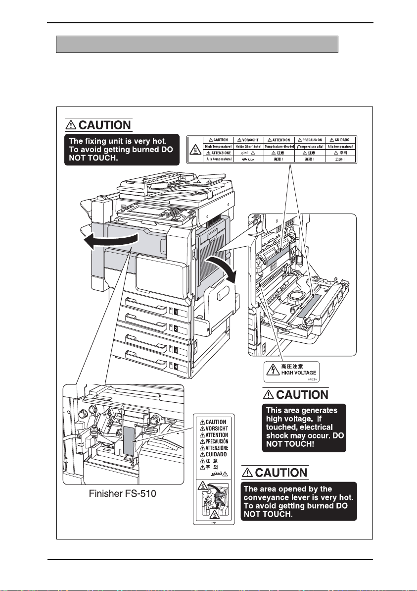
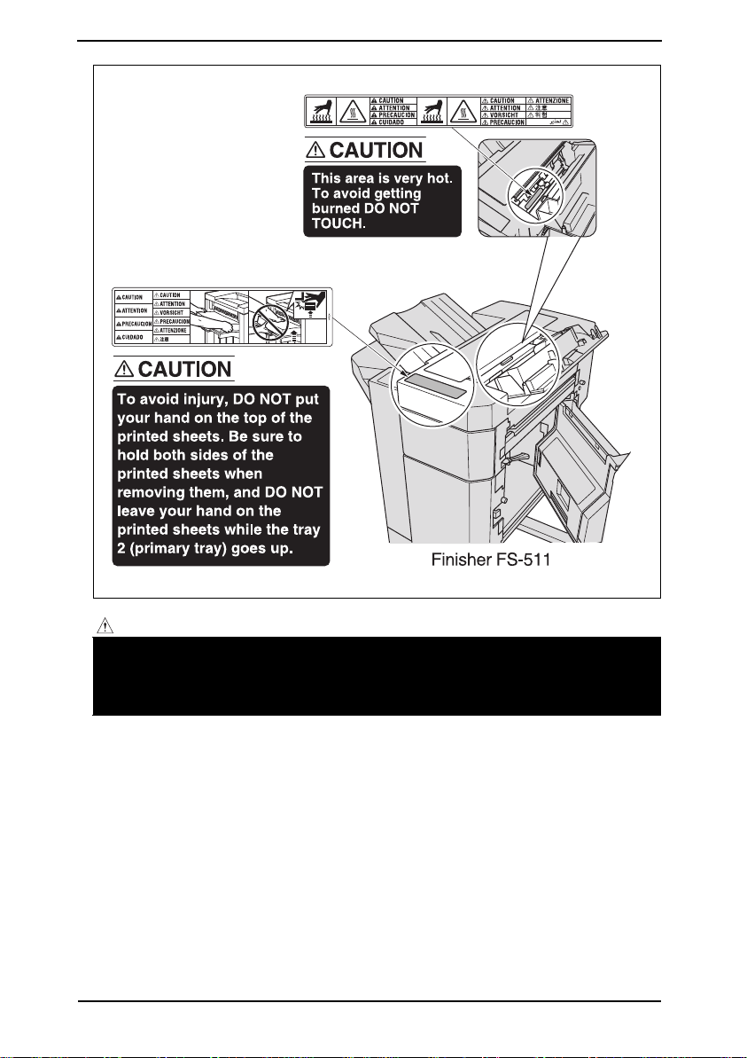
INDICATION OF WARNING ON THE MACHINE
Caution labels shown below are attached in some areas on/in the machine.
When accessing these areas for maintenance, repair, or adjustment, special care should
be taken to avoid burns and electric shock.
50gap0e001na
S-13
Page 17
SAFETY INFORMATION
Confidential – for internal use only, do not distribute
CAUTION:
• You may be burned or injured if you touch any area that you are advised by any
caution label to keep yourself away from. Do not remove caution labels. And also,
when the caution label is peeled off or soiled and cannot be seen clearly, replace
it with a new caution label.
S-14
50gap0e002na
Page 18

MEASURES TO TAKE IN CASE OF AN ACCIDENT
Confidential – for internal use only, do not distribute
MEASURES TO TAKE IN CASE OF
AN ACCIDENT
1. If an accident has occurred, the distributor who has been notified first must immediately
take emergency measures to provide relief to affected persons and to prevent further
damage.
2. If a report of a serious accident has been received from a customer, an on-site evaluation must be carried out quickly and KMBT must be notified.
3. To determine the cause of the accident, conditions and materials must be recorded
through direct on-site checks, in accordance with instructions issued by KMBT.
4. For reports and measures concerning serious accidents, follow the regulations specified by every distributor.
S-15
Page 19

MEASURES TO TAKE IN CASE OF AN ACCIDENT
Confidential – for internal use only, do not distribute
Blank Page
S-16
Page 20

Composition of the service manual
Confidential – for internal use only, do not distribute
This service manual consists of the following sections and chapters:
<Theory of Operation section>
OUTLINE: System configuration, product specifications,
unit configuration, and paper path
COMPOSITION/OPERATION: Configuration of each unit, explanation of the operating
system, and explanation of the control system
This section gives, as information for the CE to get a full understanding of the product, a
rough outline of the object and role of each function, the relationship between the electrical
system and the mechanical system, and the timing of operation of each part.
<Field service section>
OUTLINE: System configuration, and product specifications
MAINTENANCE: Service schedule *, maintenance steps,
list of service tools and directions for use *,
firmware version up method *,
and removal/reinstallation methods of major parts
ADJUSTMENT/SETTING: Utility mode *, service mode *, security and mechanical
adjustment
TROUBLESHOOTING*: List of jam codes, their causes, operation when a jam
occurs and its release method, and list of error codes,
their causes, operation when a warning is issued and esti-
mated abnormal parts.
APPENDIX*: Parts layout drawings, connector layout drawings, timing
chart, overall layout drawing
This section gives, as information required by the CE at the site (or at the customer's
premise), a rough outline of the service schedule and its details, maintenance steps, the
object and role of each adjustment, error codes and supplementary information.
The details of items with an asterisk "*" are described only in the service manual of
the main body.
C-1
Page 21

Notation of the service manual
Confidential – for internal use only, do not distribute
A. Product name
In this manual, each of the products is described as follows:
(1) IC board: Standard printer
(2) bizhub 500/420/360: Main body
(3) Microsoft Windows 95: Windows 95
Microsoft Windows 98: Windows 98
Microsoft Windows Me: Windows Me
Microsoft Windows NT 4.0: Windows NT 4.0 or Windows NT
Microsoft Windows 2000: Windows 2000
Microsoft Windows XP: Windows XP
When the description is made in combination of the OS's mentioned above:
Windows 95/98/Me
Windows NT 4.0/2000
Windows NT/2000/XP
Windows 95/98/Me/NT/2000/XP
B. Brand name
The company names and product names mentioned in this manual are the brand name or
the registered trademark of each company.
C. Electrical parts and signals
Those listed by way of example below are not exhaustive, but only some instances among
many.
Classification Load symbol Ex. of signal name Description
IN
PS
Sensor PS
Solenoid SD
Clutch CL
Door PS1
SIG
102 PS
24V Power to drive the solenoid
DRV
SOL
24V Power to drive the clutch
DRV
SOL
C-2
Sensor detection signal
Drive signal
Drive signal
Page 22

Classification Load symbol Ex. of signal name Description
Confidential – for internal use only, do not distribute
24V Power to drive the motor
CONT Drive signal
Motor M
Motor M
Fan FM
Others TH1.S, ANG Analog signal
DRV1
DRV2
D1
D2
_U
_V
_W
DRV1
DRV2
DRV3
D1
D2
D3
D4
DRV A
DRV A
DRV B
DRV B
A
/A
B
/B
AB
BB
CLK, PLL PLL control signal
LCK, Lock, LD PLL lock signal
FR Forward/reverse rotation signal
EM, Lock, LCK, LD Motor lock abnormality
BLK Drive brake signal
P/S Power/stop
S/S
SS
CW/CCW, F/R Rotational direction switching signal
ENB Effective signal
TEMP_ER Motor temperature abnormality detection signal
24V Power to drive the fan motor
CONT, DRIVE Drive signal
HL Speed control signal (2 speeds)
EM, Lock, LCK, FEM Detection signal
Drive signals of two kinds
Drive signals (control signals) of three kinds
Drive signals (control signals) of four kinds
Motor, phases A and B control signals
Operating load start/stop signal
C-3
Page 23

Classification Load symbol Ex. of signal name Description
Confidential – for internal use only, do not distribute
Ground
Serial com-
munication
SG, S.GND, S_GND Signal ground
PG, P.GND Power ground
DCD Data carrier detection
SIN Serial input
SOUT Serial output
DTR Data terminal operation available
GND Signal ground (earth)
DSR, DSET Data set ready
RTS Transmission request signal
CTS Consent transmission signal
RI Ring indicator
TXD Serial transmission data
RXD Serial reception data
D. Paper feed direction
When the direction in which paper is fed is in parallel with the longer side of paper, the
paper feed direction like this is referred to as the longitudinal feed.
And the paper feed direction that is perpendicular to the longitudinal feed is referred to as
the transverse feed.
When specifying the longitudinal feed, "S (abbreviation for Short Edge Feeding)" is added
to the paper size. For the transverse feed, no specific notation is employed.
However, when only the longitudinal feed is specified for one and the same paper size with
no specification made for the transverse feed, "S" is not added even when being fed longi-
tudinally.
<Example>
Paper size Feed direction Notation
A4
A3 Longitudinal feed A3
Transverse feed A4
Longitudinal feed A4S
C-4
Page 24

SERVICE MANUAL
Confidential – for internal use only, do not distribute
500/420/360
Main body
Theory of Operation
2007.01
Ver. 2.0
Page 25

Revision history
Confidential – for internal use only, do not distribute
After publication of this service manual, the parts and mechanism may be subject to change for
improvement of their performance.
Therefore, the descriptions given in this service manual may not coincide with the actual machine.
When any change has been made to the descriptions in the service manual, a revised version will be
issued with a revision mark added as required.
Revision mark:
• To indicate clearly a section revised, show to the left of the revised section.
A number within represents the number of times the revision has been made.
1
1
• To indicate clearly a section revised, show in the lower outside section of the correspond-
1
ing page.
A number within represents the number of times the revision has been made.
1
NOTE
Revision marks shown in a page are restricted only to the latest ones with the old ones deleted.
• When a page revised in Ver. 2.0 has been changed in Ver. 3.0:
The revision marks for Ver. 3.0 only are shown with those for Ver. 2.0 deleted.
• When a page revised in Ver. 2.0 has not been changed in Ver. 3.0:
The revision marks for Ver. 2.0 are left as they are.
2007/01 2.0 Revision in relation to launching of bizhub 360
2006/02 1.0 — Issue of the first edition
Date Service manual Ver. Revision mark Descriptions of revision
Page 26

Theory of Operation Ver.2.0 Jan. 2007
Confidential – for internal use only, do not distribute
bizhub 500/420/360
CONTENTS
CONTENTS
OUTLINE
1. SYSTEM CONFIGURATION . . . . . . . . . . . . . . . . . . . . . . . . . . . . . . . . . . . . . . . . . . . . . . . . . . . . . . . . . . . . 1
2. PRODUCT SPECIFICATIONS. . . . . . . . . . . . . . . . . . . . . . . . . . . . . . . . . . . . . . . . . . . . . . . . . . . . . . . . . . . 3
3. UNIT CONFIGURATION . . . . . . . . . . . . . . . . . . . . . . . . . . . . . . . . . . . . . . . . . . . . . . . . . . . . . . . . . . . . . . . 7
4. PAPER PATH. . . . . . . . . . . . . . . . . . . . . . . . . . . . . . . . . . . . . . . . . . . . . . . . . . . . . . . . . . . . . . . . . . . . . . . 8
COMPOSITION/OPERATION
5. OVERALL CONFIGURATION . . . . . . . . . . . . . . . . . . . . . . . . . . . . . . . . . . . . . . . . . . . . . . . . . . . . . . . . . . . 9
5.1 Time chart when the power is turned ON . . . . . . . . . . . . . . . . . . . . . . . . . . . . . . . . . . . . . . . . . . . . . . 9
5.2 Control block diagram . . . . . . . . . . . . . . . . . . . . . . . . . . . . . . . . . . . . . . . . . . . . . . . . . . . . . . . . . . . . 10
6. SCANNER SECTION . . . . . . . . . . . . . . . . . . . . . . . . . . . . . . . . . . . . . . . . . . . . . . . . . . . . . . . . . . . . . . . . 11
6.1 Composition . . . . . . . . . . . . . . . . . . . . . . . . . . . . . . . . . . . . . . . . . . . . . . . . . . . . . . . . . . . . . . . . . . . 11
6.2 Drive . . . . . . . . . . . . . . . . . . . . . . . . . . . . . . . . . . . . . . . . . . . . . . . . . . . . . . . . . . . . . . . . . . . . . . . . . 11
6.3 Operation . . . . . . . . . . . . . . . . . . . . . . . . . . . . . . . . . . . . . . . . . . . . . . . . . . . . . . . . . . . . . . . . . . . . . 12
6.3.1 Scan/exposure lamp control . . . . . . . . . . . . . . . . . . . . . . . . . . . . . . . . . . . . . . . . . . . . . . . . . . 12
6.3.2 Original size detection control. . . . . . . . . . . . . . . . . . . . . . . . . . . . . . . . . . . . . . . . . . . . . . . . . . 15
6.3.3 AE control . . . . . . . . . . . . . . . . . . . . . . . . . . . . . . . . . . . . . . . . . . . . . . . . . . . . . . . . . . . . . . . . 16
6.3.4 Image processing. . . . . . . . . . . . . . . . . . . . . . . . . . . . . . . . . . . . . . . . . . . . . . . . . . . . . . . . . . . 17
7. WRITE SECTION . . . . . . . . . . . . . . . . . . . . . . . . . . . . . . . . . . . . . . . . . . . . . . . . . . . . . . . . . . . . . . . . . . . 18
7.1 Composition . . . . . . . . . . . . . . . . . . . . . . . . . . . . . . . . . . . . . . . . . . . . . . . . . . . . . . . . . . . . . . . . . . . 18
7.2 Operation . . . . . . . . . . . . . . . . . . . . . . . . . . . . . . . . . . . . . . . . . . . . . . . . . . . . . . . . . . . . . . . . . . . . . 19
7.2.1 Laser beam path . . . . . . . . . . . . . . . . . . . . . . . . . . . . . . . . . . . . . . . . . . . . . . . . . . . . . . . . . . . 19
7.2.2 Write control . . . . . . . . . . . . . . . . . . . . . . . . . . . . . . . . . . . . . . . . . . . . . . . . . . . . . . . . . . . . . . 19
7.2.3 Image stabilization control . . . . . . . . . . . . . . . . . . . . . . . . . . . . . . . . . . . . . . . . . . . . . . . . . . . . 19
7.2.4 Image processing. . . . . . . . . . . . . . . . . . . . . . . . . . . . . . . . . . . . . . . . . . . . . . . . . . . . . . . . . . . 20
8. PHOTO CONDUCTOR SECTION . . . . . . . . . . . . . . . . . . . . . . . . . . . . . . . . . . . . . . . . . . . . . . . . . . . . . . . 21
8.1 Composition . . . . . . . . . . . . . . . . . . . . . . . . . . . . . . . . . . . . . . . . . . . . . . . . . . . . . . . . . . . . . . . . . . . 21
8.2 Drive . . . . . . . . . . . . . . . . . . . . . . . . . . . . . . . . . . . . . . . . . . . . . . . . . . . . . . . . . . . . . . . . . . . . . . . . . 22
8.2.1 Drum drive . . . . . . . . . . . . . . . . . . . . . . . . . . . . . . . . . . . . . . . . . . . . . . . . . . . . . . . . . . . . . . . . 22
8.2.2 Drum claw drive . . . . . . . . . . . . . . . . . . . . . . . . . . . . . . . . . . . . . . . . . . . . . . . . . . . . . . . . . . . . 22
8.3 Operation . . . . . . . . . . . . . . . . . . . . . . . . . . . . . . . . . . . . . . . . . . . . . . . . . . . . . . . . . . . . . . . . . . . . . 23
8.3.1 Image creation control . . . . . . . . . . . . . . . . . . . . . . . . . . . . . . . . . . . . . . . . . . . . . . . . . . . . . . . 23
8.3.2 Drum claw control . . . . . . . . . . . . . . . . . . . . . . . . . . . . . . . . . . . . . . . . . . . . . . . . . . . . . . . . . . 24
8.3.3 Image stabilization control . . . . . . . . . . . . . . . . . . . . . . . . . . . . . . . . . . . . . . . . . . . . . . . . . . . . 24
9. CHARGING SECTION . . . . . . . . . . . . . . . . . . . . . . . . . . . . . . . . . . . . . . . . . . . . . . . . . . . . . . . . . . . . . . . 25
9.1 Composition . . . . . . . . . . . . . . . . . . . . . . . . . . . . . . . . . . . . . . . . . . . . . . . . . . . . . . . . . . . . . . . . . . . 25
9.2 Operation . . . . . . . . . . . . . . . . . . . . . . . . . . . . . . . . . . . . . . . . . . . . . . . . . . . . . . . . . . . . . . . . . . . . . 25
9.2.1 Charging control . . . . . . . . . . . . . . . . . . . . . . . . . . . . . . . . . . . . . . . . . . . . . . . . . . . . . . . . . . . 25
9.2.2 Erase lamp (EL) control . . . . . . . . . . . . . . . . . . . . . . . . . . . . . . . . . . . . . . . . . . . . . . . . . . . . . . 25
10. TRANSFER/SEPARATION SECTION . . . . . . . . . . . . . . . . . . . . . . . . . . . . . . . . . . . . . . . . . . . . . . . . . . . . 26
10.1 Composition . . . . . . . . . . . . . . . . . . . . . . . . . . . . . . . . . . . . . . . . . . . . . . . . . . . . . . . . . . . . . . . . . . . 26
10.2 Operation . . . . . . . . . . . . . . . . . . . . . . . . . . . . . . . . . . . . . . . . . . . . . . . . . . . . . . . . . . . . . . . . . . . . . 27
10.2.1 Transfer guide control . . . . . . . . . . . . . . . . . . . . . . . . . . . . . . . . . . . . . . . . . . . . . . . . . . . . . . . 27
10.2.2 Transfer/separation control . . . . . . . . . . . . . . . . . . . . . . . . . . . . . . . . . . . . . . . . . . . . . . . . . . . 27
bizhub 500/420/360
i
Page 27

CONTENTS
Confidential – for internal use only, do not distribute
10.2.3 Transfer exposure lamp (TSL) control . . . . . . . . . . . . . . . . . . . . . . . . . . . . . . . . . . . . . . . . . . . .27
11.DEVELOPING UNIT . . . . . . . . . . . . . . . . . . . . . . . . . . . . . . . . . . . . . . . . . . . . . . . . . . . . . . . . . . . . . . . . . 28
11.1 Composition . . . . . . . . . . . . . . . . . . . . . . . . . . . . . . . . . . . . . . . . . . . . . . . . . . . . . . . . . . . . . . . . . . . 28
11.2 Drive . . . . . . . . . . . . . . . . . . . . . . . . . . . . . . . . . . . . . . . . . . . . . . . . . . . . . . . . . . . . . . . . . . . . . . . . . 29
11.3 Operation . . . . . . . . . . . . . . . . . . . . . . . . . . . . . . . . . . . . . . . . . . . . . . . . . . . . . . . . . . . . . . . . . . . . . 30
bizhub 500/420/360
11.3.1 Developer conveyance . . . . . . . . . . . . . . . . . . . . . . . . . . . . . . . . . . . . . . . . . . . . . . . . . . . . . . . 30
11.3.2 Developing bias . . . . . . . . . . . . . . . . . . . . . . . . . . . . . . . . . . . . . . . . . . . . . . . . . . . . . . . . . . . . 31
11.3.3 Developing suction control . . . . . . . . . . . . . . . . . . . . . . . . . . . . . . . . . . . . . . . . . . . . . . . . . . . . 32
11.3.4 Image stabilization control . . . . . . . . . . . . . . . . . . . . . . . . . . . . . . . . . . . . . . . . . . . . . . . . . . . . 32
12. TONER SUPPLY SECTION. . . . . . . . . . . . . . . . . . . . . . . . . . . . . . . . . . . . . . . . . . . . . . . . . . . . . . . . . . . . 33
12.1 Composition . . . . . . . . . . . . . . . . . . . . . . . . . . . . . . . . . . . . . . . . . . . . . . . . . . . . . . . . . . . . . . . . . . . 33
12.2 Drive . . . . . . . . . . . . . . . . . . . . . . . . . . . . . . . . . . . . . . . . . . . . . . . . . . . . . . . . . . . . . . . . . . . . . . . . . 34
12.3 Operation . . . . . . . . . . . . . . . . . . . . . . . . . . . . . . . . . . . . . . . . . . . . . . . . . . . . . . . . . . . . . . . . . . . . . 35
12.3.1 Toner level detection control . . . . . . . . . . . . . . . . . . . . . . . . . . . . . . . . . . . . . . . . . . . . . . . . . . . 35
12.3.2 Toner supply control to the toner hopper . . . . . . . . . . . . . . . . . . . . . . . . . . . . . . . . . . . . . . . . .35
12.3.3 Toner supply control to the developing unit . . . . . . . . . . . . . . . . . . . . . . . . . . . . . . . . . . . . . . . 35
12.3.4 Toner conveyance control . . . . . . . . . . . . . . . . . . . . . . . . . . . . . . . . . . . . . . . . . . . . . . . . . . . . 36
13. CLEANING/TONER RECYCLE SECTION . . . . . . . . . . . . . . . . . . . . . . . . . . . . . . . . . . . . . . . . . . . . . . . . . 37
13.1 Composition . . . . . . . . . . . . . . . . . . . . . . . . . . . . . . . . . . . . . . . . . . . . . . . . . . . . . . . . . . . . . . . . . . . 37
13.2 Drive . . . . . . . . . . . . . . . . . . . . . . . . . . . . . . . . . . . . . . . . . . . . . . . . . . . . . . . . . . . . . . . . . . . . . . . . . 38
13.3 Operation . . . . . . . . . . . . . . . . . . . . . . . . . . . . . . . . . . . . . . . . . . . . . . . . . . . . . . . . . . . . . . . . . . . . . 39
13.3.1 Cleaning operation . . . . . . . . . . . . . . . . . . . . . . . . . . . . . . . . . . . . . . . . . . . . . . . . . . . . . . . . . . 39
13.3.2 Toner collection mechanism . . . . . . . . . . . . . . . . . . . . . . . . . . . . . . . . . . . . . . . . . . . . . . . . . . . 39
13.3.3 Toner conveyance operation . . . . . . . . . . . . . . . . . . . . . . . . . . . . . . . . . . . . . . . . . . . . . . . . . . 39
14. PAPER FEED SECTION (Tray 1/2) . . . . . . . . . . . . . . . . . . . . . . . . . . . . . . . . . . . . . . . . . . . . . . . . . . . . . . 40
14.1 Composition . . . . . . . . . . . . . . . . . . . . . . . . . . . . . . . . . . . . . . . . . . . . . . . . . . . . . . . . . . . . . . . . . . . 40
14.1.1 Tray 1. . . . . . . . . . . . . . . . . . . . . . . . . . . . . . . . . . . . . . . . . . . . . . . . . . . . . . . . . . . . . . . . . . . . 40
14.1.2 Tray 2. . . . . . . . . . . . . . . . . . . . . . . . . . . . . . . . . . . . . . . . . . . . . . . . . . . . . . . . . . . . . . . . . . . . 40
14.2 Drive . . . . . . . . . . . . . . . . . . . . . . . . . . . . . . . . . . . . . . . . . . . . . . . . . . . . . . . . . . . . . . . . . . . . . . . . . 41
14.2.1 Paper feed drive . . . . . . . . . . . . . . . . . . . . . . . . . . . . . . . . . . . . . . . . . . . . . . . . . . . . . . . . . . . . 41
14.2.2 Tray lift drive . . . . . . . . . . . . . . . . . . . . . . . . . . . . . . . . . . . . . . . . . . . . . . . . . . . . . . . . . . . . . . . 41
14.3 Operation . . . . . . . . . . . . . . . . . . . . . . . . . . . . . . . . . . . . . . . . . . . . . . . . . . . . . . . . . . . . . . . . . . . . . 42
14.3.1 Up/down control . . . . . . . . . . . . . . . . . . . . . . . . . . . . . . . . . . . . . . . . . . . . . . . . . . . . . . . . . . . 42
14.3.2 Paper size detection control . . . . . . . . . . . . . . . . . . . . . . . . . . . . . . . . . . . . . . . . . . . . . . . . . . . 43
14.3.3 Paper feed control . . . . . . . . . . . . . . . . . . . . . . . . . . . . . . . . . . . . . . . . . . . . . . . . . . . . . . . . . . 45
14.3.4 Paper empty control . . . . . . . . . . . . . . . . . . . . . . . . . . . . . . . . . . . . . . . . . . . . . . . . . . . . . . . . . 48
14.3.5 Paper remaining detection mechanism. . . . . . . . . . . . . . . . . . . . . . . . . . . . . . . . . . . . . . . . . . . 49
15. BYPASS SECTION . . . . . . . . . . . . . . . . . . . . . . . . . . . . . . . . . . . . . . . . . . . . . . . . . . . . . . . . . . . . . . . . . . 50
15.1 Composition . . . . . . . . . . . . . . . . . . . . . . . . . . . . . . . . . . . . . . . . . . . . . . . . . . . . . . . . . . . . . . . . . . . 50
15.2 Drive . . . . . . . . . . . . . . . . . . . . . . . . . . . . . . . . . . . . . . . . . . . . . . . . . . . . . . . . . . . . . . . . . . . . . . . . . 51
15.2.1 Paper feed drive . . . . . . . . . . . . . . . . . . . . . . . . . . . . . . . . . . . . . . . . . . . . . . . . . . . . . . . . . . . . 51
15.2.2 Tray lift drive . . . . . . . . . . . . . . . . . . . . . . . . . . . . . . . . . . . . . . . . . . . . . . . . . . . . . . . . . . . . . . . 51
15.3 Operation . . . . . . . . . . . . . . . . . . . . . . . . . . . . . . . . . . . . . . . . . . . . . . . . . . . . . . . . . . . . . . . . . . . . . 52
15.3.1 Up/down control . . . . . . . . . . . . . . . . . . . . . . . . . . . . . . . . . . . . . . . . . . . . . . . . . . . . . . . . . . . 52
15.3.2 Paper size detection control . . . . . . . . . . . . . . . . . . . . . . . . . . . . . . . . . . . . . . . . . . . . . . . . . . . 53
15.3.3 Paper feed control . . . . . . . . . . . . . . . . . . . . . . . . . . . . . . . . . . . . . . . . . . . . . . . . . . . . . . . . . . 54
15.3.4 Paper empty control . . . . . . . . . . . . . . . . . . . . . . . . . . . . . . . . . . . . . . . . . . . . . . . . . . . . . . . . . 55
16. REGISTRATION SECTION . . . . . . . . . . . . . . . . . . . . . . . . . . . . . . . . . . . . . . . . . . . . . . . . . . . . . . . . . . . . 56
16.1 Composition . . . . . . . . . . . . . . . . . . . . . . . . . . . . . . . . . . . . . . . . . . . . . . . . . . . . . . . . . . . . . . . . . . . 56
16.2 Drive . . . . . . . . . . . . . . . . . . . . . . . . . . . . . . . . . . . . . . . . . . . . . . . . . . . . . . . . . . . . . . . . . . . . . . . . . 57
Theory of Operation Ver.2.0 Jan. 2007
ii
Page 28

Theory of Operation Ver.2.0 Jan. 2007
Confidential – for internal use only, do not distribute
16.3 Operation . . . . . . . . . . . . . . . . . . . . . . . . . . . . . . . . . . . . . . . . . . . . . . . . . . . . . . . . . . . . . . . . . . . . . 58
16.3.1 Loop control . . . . . . . . . . . . . . . . . . . . . . . . . . . . . . . . . . . . . . . . . . . . . . . . . . . . . . . . . . . . . . 58
17. ADU SECTION . . . . . . . . . . . . . . . . . . . . . . . . . . . . . . . . . . . . . . . . . . . . . . . . . . . . . . . . . . . . . . . . . . . . . 60
17.1 Composition . . . . . . . . . . . . . . . . . . . . . . . . . . . . . . . . . . . . . . . . . . . . . . . . . . . . . . . . . . . . . . . . . . . 60
17.2 Drive . . . . . . . . . . . . . . . . . . . . . . . . . . . . . . . . . . . . . . . . . . . . . . . . . . . . . . . . . . . . . . . . . . . . . . . . . 61
17.3 Operation . . . . . . . . . . . . . . . . . . . . . . . . . . . . . . . . . . . . . . . . . . . . . . . . . . . . . . . . . . . . . . . . . . . . . 62
17.3.1 Conveyance path . . . . . . . . . . . . . . . . . . . . . . . . . . . . . . . . . . . . . . . . . . . . . . . . . . . . . . . . . . . 62
17.3.2 Conveyance control . . . . . . . . . . . . . . . . . . . . . . . . . . . . . . . . . . . . . . . . . . . . . . . . . . . . . . . . . 63
18. FUSING SECTION . . . . . . . . . . . . . . . . . . . . . . . . . . . . . . . . . . . . . . . . . . . . . . . . . . . . . . . . . . . . . . . . . . 71
18.1 Composition . . . . . . . . . . . . . . . . . . . . . . . . . . . . . . . . . . . . . . . . . . . . . . . . . . . . . . . . . . . . . . . . . . . 71
18.2 Drive . . . . . . . . . . . . . . . . . . . . . . . . . . . . . . . . . . . . . . . . . . . . . . . . . . . . . . . . . . . . . . . . . . . . . . . . . 71
18.3 Operation . . . . . . . . . . . . . . . . . . . . . . . . . . . . . . . . . . . . . . . . . . . . . . . . . . . . . . . . . . . . . . . . . . . . . 72
18.3.1 Fusing roller drive control . . . . . . . . . . . . . . . . . . . . . . . . . . . . . . . . . . . . . . . . . . . . . . . . . . . . . 72
18.3.2 Web drive control . . . . . . . . . . . . . . . . . . . . . . . . . . . . . . . . . . . . . . . . . . . . . . . . . . . . . . . . . . . 72
18.3.3 Fusing temperature control . . . . . . . . . . . . . . . . . . . . . . . . . . . . . . . . . . . . . . . . . . . . . . . . . . . 73
18.3.4 Fusing roller edge cooling control. . . . . . . . . . . . . . . . . . . . . . . . . . . . . . . . . . . . . . . . . . . . . . . 74
18.3.5 Envelope conveyance mechanism . . . . . . . . . . . . . . . . . . . . . . . . . . . . . . . . . . . . . . . . . . . . . . 75
18.3.6 Protection against abnormality . . . . . . . . . . . . . . . . . . . . . . . . . . . . . . . . . . . . . . . . . . . . . . . . . 76
18.3.7 Jam detection control . . . . . . . . . . . . . . . . . . . . . . . . . . . . . . . . . . . . . . . . . . . . . . . . . . . . . . . 76
19. REVERSE/EXIT SECTION. . . . . . . . . . . . . . . . . . . . . . . . . . . . . . . . . . . . . . . . . . . . . . . . . . . . . . . . . . . . . 77
19.1 Composition . . . . . . . . . . . . . . . . . . . . . . . . . . . . . . . . . . . . . . . . . . . . . . . . . . . . . . . . . . . . . . . . . . . 77
19.2 Drive . . . . . . . . . . . . . . . . . . . . . . . . . . . . . . . . . . . . . . . . . . . . . . . . . . . . . . . . . . . . . . . . . . . . . . . . . 77
19.3 Operation . . . . . . . . . . . . . . . . . . . . . . . . . . . . . . . . . . . . . . . . . . . . . . . . . . . . . . . . . . . . . . . . . . . . . 78
19.3.1 Conveyance control . . . . . . . . . . . . . . . . . . . . . . . . . . . . . . . . . . . . . . . . . . . . . . . . . . . . . . . . . 78
19.3.2 Reverse control . . . . . . . . . . . . . . . . . . . . . . . . . . . . . . . . . . . . . . . . . . . . . . . . . . . . . . . . . . . . 80
20. INTERFACE SECTION . . . . . . . . . . . . . . . . . . . . . . . . . . . . . . . . . . . . . . . . . . . . . . . . . . . . . . . . . . . . . . . 82
20.1 Composition . . . . . . . . . . . . . . . . . . . . . . . . . . . . . . . . . . . . . . . . . . . . . . . . . . . . . . . . . . . . . . . . . . . 82
20.2 Specifications . . . . . . . . . . . . . . . . . . . . . . . . . . . . . . . . . . . . . . . . . . . . . . . . . . . . . . . . . . . . . . . . . . 82
21. IMAGE STABILIZATION CONTROL . . . . . . . . . . . . . . . . . . . . . . . . . . . . . . . . . . . . . . . . . . . . . . . . . . . . . 83
21.1 Outline . . . . . . . . . . . . . . . . . . . . . . . . . . . . . . . . . . . . . . . . . . . . . . . . . . . . . . . . . . . . . . . . . . . . . . . 83
21.2 Operation flow. . . . . . . . . . . . . . . . . . . . . . . . . . . . . . . . . . . . . . . . . . . . . . . . . . . . . . . . . . . . . . . . . . 83
21.2.1 Image stabilization control flow when the power switch (SW2) is turned ON . . . . . . . . . . . . . . . 83
21.2.2 Image stabilization control flow while in the print and the idle . . . . . . . . . . . . . . . . . . . . . . . . . . 86
22. IMAGE PROCESSING . . . . . . . . . . . . . . . . . . . . . . . . . . . . . . . . . . . . . . . . . . . . . . . . . . . . . . . . . . . . . . . 88
22.1 Image processing in the scanner section. . . . . . . . . . . . . . . . . . . . . . . . . . . . . . . . . . . . . . . . . . . . . . 88
22.1.1 Shading correction . . . . . . . . . . . . . . . . . . . . . . . . . . . . . . . . . . . . . . . . . . . . . . . . . . . . . . . . . . 89
22.1.2 AE control . . . . . . . . . . . . . . . . . . . . . . . . . . . . . . . . . . . . . . . . . . . . . . . . . . . . . . . . . . . . . . . . 90
22.1.3 Area discrimination. . . . . . . . . . . . . . . . . . . . . . . . . . . . . . . . . . . . . . . . . . . . . . . . . . . . . . . . . . 91
22.1.4 Brightness/density conversion . . . . . . . . . . . . . . . . . . . . . . . . . . . . . . . . . . . . . . . . . . . . . . . . . 91
22.1.5 Filter/magnification . . . . . . . . . . . . . . . . . . . . . . . . . . . . . . . . . . . . . . . . . . . . . . . . . . . . . . . . . . 92
22.1.6 Scanner gamma correction . . . . . . . . . . . . . . . . . . . . . . . . . . . . . . . . . . . . . . . . . . . . . . . . . . . 94
22.1.7 Halftone processing (error diffusion) . . . . . . . . . . . . . . . . . . . . . . . . . . . . . . . . . . . . . . . . . . . . . 94
22.1.8 Compression . . . . . . . . . . . . . . . . . . . . . . . . . . . . . . . . . . . . . . . . . . . . . . . . . . . . . . . . . . . . . . 94
22.1.9 Storage of image data . . . . . . . . . . . . . . . . . . . . . . . . . . . . . . . . . . . . . . . . . . . . . . . . . . . . . . . 94
22.2 Image processing in the write section . . . . . . . . . . . . . . . . . . . . . . . . . . . . . . . . . . . . . . . . . . . . . . . . 95
23. OTHERS . . . . . . . . . . . . . . . . . . . . . . . . . . . . . . . . . . . . . . . . . . . . . . . . . . . . . . . . . . . . . . . . . . . . . . . . . 96
23.1 Fan control . . . . . . . . . . . . . . . . . . . . . . . . . . . . . . . . . . . . . . . . . . . . . . . . . . . . . . . . . . . . . . . . . . . . 96
23.1.1 Composition . . . . . . . . . . . . . . . . . . . . . . . . . . . . . . . . . . . . . . . . . . . . . . . . . . . . . . . . . . . . . . 96
23.1.2 Operation. . . . . . . . . . . . . . . . . . . . . . . . . . . . . . . . . . . . . . . . . . . . . . . . . . . . . . . . . . . . . . . . . 97
23.2 Counter control . . . . . . . . . . . . . . . . . . . . . . . . . . . . . . . . . . . . . . . . . . . . . . . . . . . . . . . . . . . . . . . . 100
CONTENTS
bizhub 500/420/360
iii
Page 29

CONTENTS
Confidential – for internal use only, do not distribute
23.2.1 Composition. . . . . . . . . . . . . . . . . . . . . . . . . . . . . . . . . . . . . . . . . . . . . . . . . . . . . . . . . . . . . . 100
23.2.2 Operation . . . . . . . . . . . . . . . . . . . . . . . . . . . . . . . . . . . . . . . . . . . . . . . . . . . . . . . . . . . . . . . . 101
23.3 Parts that operate when the power switch is turned ON . . . . . . . . . . . . . . . . . . . . . . . . . . . . . . . . . 103
23.3.1 Parts that operate when the main power switch (SW1) is turned ON . . . . . . . . . . . . . . . . . . . 103
23.3.2 Parts that operate when the power switch (SW2) is turned ON . . . . . . . . . . . . . . . . . . . . . . . . 104
bizhub 500/420/360
Theory of Operation Ver.2.0 Jan. 2007
iv
Page 30

Theory of Operation Ver.2.0 Jan. 2007
Confidential – for internal use only, do not distribute
OUTLINE
1. SYSTEM CONFIGURATION
A. System configuration
[23]
[21]
[24]
[22]
[25]
[26]
[27]
[28] [29]
[1]
[2]
1. SYSTEM CONFIGURATION
[5]
[6]
[7]
[3]
[4]
[8]
[9]
bizhub 500/420/360
[19]
[17]
[1] Reverse automatic document feeder
(DF-607) (standard equipment)
[2] Main body [17] Finisher (FS-511)
[3] Image controller (IC-204) [18] Swedish punch kit G *3
[4] Hard disk (HD-505) [19] Job separator (JS-502)
[5] Stamp unit (SP-501) [20] Output tray kit (OT-501)
[6] Spare TX marker stamp 2 [21] Output tray (OT-601)
[7] Key counter kit 4 *1 [22] Finisher (FS-510)
[8] Key counter *1 [23] Mail bin kit (MT-501)
[9] Key counter mount kit *1 [24] Saddle stitcher (SD-502)
[10] Dehumidifier heater 1C [25] Folding unit (included in SD-502)
[11] Paper feed cabinet (PC-402) [26] Punch unit (PU-501)
[12] Paper feed cabinet (PC-202) [27] FAX kit (FK-502)
[13] Desk (DK-501) [28] Mount kit (MK-708)
[14] Large capacity unit (LU-201) [29] FAX multi line (ML-503)
*1 See "6.4 Option counter" in Field Service bizhub 500/420/360 main body for details.
*2 Dehumidifier heater is set up as service part.
*3 Swedish punch kit G is for Europe only.
[20]
[18]
[10]
[16]
[10]
[15] Dehumidifier heater *2
[16] Relay unit (RU-502)
[11]
[12]
[13]
[14]
[15]
50gat1e001nb
1
1
Page 31

1. SYSTEM CONFIGURATION
Confidential – for internal use only, do not distribute
B. Configuration for optional device connection
Note
• Any combination other than those listed below is not available.
Theory of Operation Ver.2.0 Jan. 2007
bizhub 500/420/360
No. Combinations for paper feeding Combinations for finishing Remarks
1 DK-501/PC-202/PC-402 *1 OT-501
2 DK-501/PC-202/PC-402 *1 OT-501 JS-502
3 DK-501/PC-202/PC-402 *1 RU-502 + FS-511
4 DK-501/PC-202/PC-402 *1 FS-510 *2*3
5 DK-501/PC-202/PC-402 *1 FS-510 *2*3 SD-502
6 DK-501/PC-202/PC-402 *1 FS-510 *2*3 MT-501
7 PC-202/PC-402 *4 LU-201 OT-501
8 PC-202/PC-402 *4 LU-201 OT-501 JS-502
9 PC-202/PC-402 *4 LU-201 RU-502 + FS-511
10 PC-202/PC-402 *4 LU-201 FS-510 *2*3
11 PC-202/PC-402 *4 LU-201 FS-510 *2*3 SD-502
12 PC-202/PC-402 *4 LU-201 FS-510 *2*3 MT-501
*1 Either one of DK-501, PC-202 and PC-402 can be selected.
*2 FS-510 can be installed optionally with OT-601.
*3 FS-510 can be installed optionally with PU-501.
*4 Either one of PC-202 and PC-402 can be selected.
2
Page 32

Theory of Operation Ver.2.0 Jan. 2007
Confidential – for internal use only, do not distribute
2. PRODUCT SPECIFICATIONS
A. Type
Type Desktop type
Copying method Indirect electrostatic method
Original stand Fixed
Original alignment Left rear standard
Photo conductor OPC
Sensitizing method Laser writing
Paper feed trays Two trays 500 sheet x 2, 80g/m
Bypass feed 150 sheet x 1, 80g/m
PC-402 *1 2,500 sheet x 1, 80g/m
PC-202 *1 500 sheet x 1, 80g/m
LU-201 *1 2,000 sheet x 1, 80g/m
*1 PC-402, PC-404, and LU-201 are optional.
2. PRODUCT SPECIFICATIONS
bizhub 500/420/360
2
2
2
2
2
3
Page 33

2. PRODUCT SPECIFICATIONS
Confidential – for internal use only, do not distribute
B. Functions
Original Sheet, book, solid object
Max. original size A3 or 11 x 17
Copy size Trays 1, 2 Inch: 11 x 17, 8
bizhub 500/420/360
Magnification Fixed magnifica-
Warm-up time 60 seconds or less (bizhub 500)
First copy out time 3.2 seconds or less (bizhub 500)
Continuous copy speed 50 copies /min. (A4 / 8
Continuous copy count Up to 999 sheets
Original density selection Auto density selection, Manual (9 steps), Manual underprint density (9 steps)
Resolution Scan 600 x 600 dpi
Memory Standard 192 MB Breakdown: 64 MB (on board) + 128 MB (DIMM)
Interface section RJ45 Ethernet, Serial port (RS232-C), Serial port (USB TypeB),
*1 256 MB (DIMM) is available from distributors.
Specification: 144 pin SO-DIMM, PC100/PC133 MHz Compliant
*2 1 port when MK-708 and FK-502 are optionally installed.
2 ports when MK-708, HL-503 and FK-502 x 2 are optionally installed.
Theory of Operation Ver.2.0 Jan. 2007
1
/2 x 14, 81/2 x 11, 81/2 x 11S, 51/2 x 81/2S,
A3, A4, A4S, A5S, Foolscap
1
Metric: A3, B4, A4, A4S, B5, A5S, 11 x 17, 8
1
/2 x 11S, Foolscap, 8K, 16K
8
Bypass feed Inch: 11 x 17, 8
1
/2 x 14, 81/2 x 11, 81/2 x 11S, 51/2 x 81/2S,
/2 x 11,
A4
1
Metric: A3, B4, A4, A4S, B5, B5S, A5S, B6S, 8
1
/2 x 11S, Foolscap, 8K, 16K, 16KS
8
ADU Inch: 11 x 17, 8
1
/2 x 14, 81/2 x 11, 81/2 x 11S, 51/2 x 81/2S,
/2 x 11,
A3, A4, A4S, A5S, Foolscap
Metric: A3, B4, A4, A4S, B5, B5S, A5S, 11 x 17, 8
1
/2 x 11S, Foolscap
8
Inch: x 1.000, x 1.214, x 1.294, x 1.545, x 2.000
tion
x 0.500, x 0.647, x 0.772, x 0.785
Metric: x 1.000, x 1.154, x 1.224, x 1.414, x 2.000
x 0.500, x 0.707, x 0.816, x 0.866
Special magnifi-
x 0.930
cation setting
Preset zoom set-
3 types
ting
Zoom magnifica-
x 0.25 to x 4.00 (at the step of 0.1%)
tion
Vertical magnifi-
x 0.25 to x 4.00 (at the step of 0.1%)
cation
Horizontal magni-
x 0.25 to x 4.00 (at the step of 0.1%)
fication
30 seconds or less (bizhub 420/360)
3.6 seconds or less (bizhub 420/360)
1
/2 x 11) (bizhub 500)
1
42 copies /min. (A4 / 8
36 copies /min. (A4 / 8
/2 x 11) (bizhub 420)
1
/2 x 11) (bizhub 360)
Write 600 x 600 dpi
Maximum 320 MB Breakdown: 64 MB (on board) + 256 MB (DIMM) *1
Parallel port (IEEE1284), RJ-11 *2
1
/2 x 11,
4
1
Page 34

Theory of Operation Ver.2.0 Jan. 2007
Confidential – for internal use only, do not distribute
2. PRODUCT SPECIFICATIONS
C. Type of paper
Plain paper *1 All trays High quality paper of 60 to 90 g/m
2
Special paper *2 Bypass feed only OHP film, label paper *3, blueprint master paper *3
High quality paper of 50 to 59 g/m
All trays High quality paper of 91 to 105 g/m
2
(thin paper)
2
Bypass feed only High quality paper of 106 to 210 g/m
*1 Standard specified paper
Plain paper: Inch: Hammermill Tidal MP (20 lbs)
Metric: Konica Minolta Original (80 g/m
Recycle paper: Inch: Weyerhaeuser Recycled Laser Copy (20 lbs)
Metric: Nautilus (80 g/m
2
)
2
), Konica Minolta Profi (80 g/m2)
*2 Special paper/recommended paper
Thick paper: Inch: Weyerhaeuser Cougar Cover 65 lbs
Metric: Xerox colortech 200 g/m
Thin paper: Inch: SOISE BOND 16 lbs
Metric: NEU 60 g/m
2
2
Label paper: Inch: AVERY 5160, 5352
Metric: AVERY DSP 24
OHP film: Inch: 3M CG3700
Metric: Folex overhead X-500, 3M CG3700
Envelope: Inch: Preservation Wove (24 lbs) #6-3/4, #9, #10 (4-1/8 x 9-1/2)
Metric: Briefhullen 211210 (100 g/m
Schneider Soehne Distinction 100 (100 g/m
Schneider Soehne (Briefumschlage) (100 g/m
2
) #C6
2
) #lang
2
) #C5
*3 Label paper is loaded and fed one sheet at a time.
(thick paper)
2
(thick paper)
bizhub 500/420/360
D. Maintenance
Maintenance Every 250,000 prints (bizhub 500/420)
Every 225,000 prints (bizhub 360)
M
1
E. Machine data
Power source Inch: AC120V 12A, 60Hz
Metric: AC220-240V 10A, 50Hz
Maximum power consump-
1,560 W or less (full option)
tion
Dimensions Main body
+ DF-607
+ PC or DK
Weight Approx. 91.2 kg
*1 Overturning prevention board is not included.
677 (W) x 708 (D) x 1,150 (H) mm *1
1
5
Page 35

2. PRODUCT SPECIFICATIONS
Confidential – for internal use only, do not distribute
F. Operating environment
Temperature 10 to 30 °C
Humidity 10 to 80%RH (with no condensation)
Note
bizhub 500/420/360
• The information herein may be subject to change for improvement without notice.
Theory of Operation Ver.2.0 Jan. 2007
6
Page 36

Theory of Operation Ver.2.0 Jan. 2007
Confidential – for internal use only, do not distribute
3. UNIT CONFIGURATION
[17]
3. UNIT CONFIGURATION
[16]
[15]
[14]
[13]
[12]
[11]
[10]
[1]
bizhub 500/420/360
[2]
[3]
[4]
[5]
[6]
[7]
[8]
[9]
[1] Scanner section [10] PC or DK (option)
[2] Paper reverse/exit section [11] Paper feed section (tray 1/2)
[3] Fusing section [12] Developing section
[4] Photo conductor section [13] Writing section
[5] ADU [14] Charging section
[6] Transfer/separation section [15] Toner supply section
[7] Registration section [16] Cleaning/toner recycle section
[8] Bypass tray section [17] DF
[9] LU (option)
50gat1c002na
7
Page 37

4. PAPER PATH
Confidential – for internal use only, do not distribute
4. PAPER PAT H
bizhub 500/420/360
[9]
[8]
Theory of Operation Ver.2.0 Jan. 2007
[1]
[7]
[6]
[5]
[1] Reverse conveyance [6] Tray 2 paper feed
[2] ADU conveyance [7] Tray 1 paper feed
[3] Bypass paper feed [8] Registration conveyance
[4] LU paper feed [9] Paper exit
[5] PC paper feed
[2]
[3]
[4]
50gat1c003na
8
Page 38

Theory of Operation Ver.2.0 Jan. 2007
Confidential – for internal use only, do not distribute
COMPOSITION/OPERATION
5. OVERALL CONFIGURATION
5. OVERALL CONFIGURATION
5.1 Time chart when the power is turned ON
[3][4] [5] [6] [7] [8] [9][1] [2]
Item
Scanner motor
(M2)
Exposure lamp (L1)
Fusing heater lamp /1 (L2)
Fusing heater lamp /2 (L3)
Fusing motor (M11)
Drum motor (M1)
Developing motor (M3)
Polygon motor (M5)
Laser (LDB)
Paper lift motor /1 (M7)
Upper limit sensor /1 (PS6)
Paper lift motor /2 (M8)
Upper limit sensor /2 (PS13)
[1] Fusing heater lamps /1 (L2) and /2 (L3) turn
ON early
[2] Power switch (SW2) turns ON [7] The fusing temperature gets to the pre-
[3] Initial communication between the overall
control board (OACB) and the printer control
board (PRCB) [8] Dot diameter adjustment completed
[4] Shading correction [9] Warming up completed
Normal
rotation
Reverse
rotation
[5] Drum motor (M1) turns ON
[6] Dot diameter adjustment starts
scribed temperature to start the preliminary
rotation for fusing
bizhub 500/420/360
50gat2e001na
Note
• Each operation varies according to the setting of the software DipSW in the service mode.
• The power is turned ON with DF closed.
• The power is turned ON with the lift plate of the tray down.
9
Page 39

5. OVERALL CONFIGURATION
Confidential – for internal use only, do not distribute
5.2 Control block diagram
Theory of Operation Ver.2.0 Jan. 2007
CCD
bizhub 500/420/360
Write
Section
M
[1] Image bus [4] Other buses
[2] Clock synchronous serial bus [5] Individual signal line
[3] UART bus [6] IDE
SDB
HDD
PS
IC
FK, MK
USB
I/F
RS232C
I/F
LAN
I/F
OACB
SC
M FM CL SD PS
PRCB
HVDCPU
[1] [2] [3] [4] [5] [6]
Parallel
I/F
PCLUJS
OB
DF
FS, RU
50gat2c090na
10
Page 40

Theory of Operation Ver.2.0 Jan. 2007
Confidential – for internal use only, do not distribute
6. SCANNER SECTION
6.1 Composition
Mirror unit
Shading
correction
plate
6.2 Drive
[3]
[4]
6. SCANNER SECTION
CCD unit
(CCDB)
Exposure unit
50gat2c001na
[5]
bizhub 500/420/360
[2]
[1] Scanner wire /Rr [4] Exposure unit
[2] Scanner wire /Fr [5] Scanner motor (M2)
[3] V-mirror unit
[1]
50gat2c002na
11
Page 41

6. SCANNER SECTION
Confidential – for internal use only, do not distribute
6.3 Operation
6.3.1 Scan/exposure lamp control
A. Operation when the power is turned ON
A specified period of time after the power switch (SW2) is turned on, the exposure unit conducts the home posi-
bizhub 500/420/360
tion search. At this time, the exposure unit conducts the shading correction based on the white reference board
attached to the original glass. For shading correction, 2 places on the white reference board are read for correc-
tion. The home position search varies according to the ON/OFF condition of the scanner home sensor (PS30)
when SW2 is turned ON.
(1) Home position search while in PS30 ON
Theory of Operation Ver.2.0 Jan. 2007
[1][2]
[6]
[5]
[1] Exposure unit stand-by position [4] Shading correction position 2
[2] Scanner home sensor (PS30) [5] Movement of the exposure unit
[3] Shading correction position 1 [6] Exposure lamp (L1) ON
(2) Home position search while in PS30 OFF
[6]
[5]
[1] Exposure unit stand-by position [4] Shading correction position 2
[2] Scanner home sensor (PS30) [5] Movement of the exposure unit
[3] Shading correction position 1 [6] Exposure lamp (L1) ON
[3]
[4]
50gat2c034na
[1][2]
[3]
[4]
50gat2c035na
12
Page 42

Theory of Operation Ver.2.0 Jan. 2007
Confidential – for internal use only, do not distribute
B. Operation when the start key is turned ON
For the original read mode, the following two types are available: the platen mode and the DF mode. While in the
platen mode, the exposure unit scans the original for reading. And while in the DF mode, since DF conveys the
original, the exposure unit remains at the prescribed position (DF read position) to read the original.
6. SCANNER SECTION
(1) When the platen is used (when DF is opened)
The operation in the platen mode varies depending on which is selected for the print density, the AE print and
the manual print.
• When the AE print is selected
[1][2][3][4]
[5]
[6]
[7]
[8]
50gat2c037na
[1] Exposure unit stand-by position [5] AE scan range
[2] Position at which the image read is started [6] Shading correction position 1
[3] Scanner home sensor (PS30) [7] Shading correction position 2
[4] Position at which the running-up of the
exposure unit is started
• When the manual print is selected
[8] Exposure lamp (L1) ON
[1][2][3][4]
[5]
[6]
[7]
50gat2c036na
bizhub 500/420/360
[1] Exposure unit stand-by position [5] Shading correction position 1
[2] Position at which the image read is started [6] Shading correction position 2
[3] Scanner home sensor (PS30) [7] Exposure lamp (L1) ON
[4] Position at which the running-up of the
exposure unit is started
Note
• When the tray 1 is selected by manual, not by APS, no shading correction is made.
13
Page 43

6. SCANNER SECTION
Confidential – for internal use only, do not distribute
(2) When DF is used (when DF is closed)
Theory of Operation Ver.2.0 Jan. 2007
[1][2][3]
bizhub 500/420/360
[1] Exposure unit stand-by position [4] Shading correction position 1
[2] Scanner home sensor (PS30) [5] Shading correction position 2
[3] DF read position [6] Exposure lamp (L1) ON
[6]
[4]
[5]
50gat2c038na
14
Page 44

Theory of Operation Ver.2.0 Jan. 2007
Confidential – for internal use only, do not distribute
6.3.2 Original size detection control
A. Detection method
The original size detection method varies for the DF mode and the platen mode.
(1) DF mode
See DF-607 Service Manual.
(2) Platen mode
• Main scan direction
Reading is made by the CCD sensor.
•Sub-scan direction
Detection is made according to the ON/OFF of the APS sensor (PS32).
Original size CCD sensor
(Detection length: mm)
PS32
(ON/OFF)
A3 297 ON
11 x 17 279.4 ON
B4 257 ON
1
/2 x 14 *1 215.9 ON
8
1
8
/2 x 11S 215.9 ON
A4S 210 ON
A4 297 OFF
1
8
/2 x 11 279.4 OFF
B5 257 OFF
A5 210 OFF
B5S 182 OFF
A5 148 OFF
1
5
/2 x 81/2 139.7 OFF
B6 128 OFF
6. SCANNER SECTION
bizhub 500/420/360
*1 No discrimination is made between 8
1
/2 x 11S.
8
B. Detection timing
(1) Platen mode (while in DF closed)
When the APS timing sensor (PS31) turns on while in DF closed, the original size is detected.
(2) Platen mode (while in DF open)
When the start key is pressed, the original size is detected.
1
/2 x 14 and 81/2 x 11S. When the size is 81/2 x 14, this is detected as
15
Page 45

6. SCANNER SECTION
Confidential – for internal use only, do not distribute
6.3.3 AE control
When AE is selected, the density level of the original is detected to adjust it to an appropriate density automati-
cally. The sampling range of the original density in the AE control varies for the platen mode and the DF mode.
(1) AE sampling range in the platen mode
bizhub 500/420/360
Theory of Operation Ver.2.0 Jan. 2007
[5]
[7]
[1]
[6]
[5]
[2]
[2]
[4]
[3]
[1] Original [5] 10 mm
[2] L/100 mm [6] Leading edge of the original
[3] L mm [7] AE sampling range
[4] 30 mm
(2) AE sampling range in the DF mode
[4]
[6]
[1]
[5]
50gat2c039na
[4]
[3]
[1] Original [4] 20 mm
[2] 2.9 mm [5] Leading edge of the original
[3] 1.5 mm [6] AE sampling range
16
[2]
50gat2c040na
Page 46

Theory of Operation Ver.2.0 Jan. 2007
Confidential – for internal use only, do not distribute
6.3.4 Image processing
The following items are provided for the image processing. For details, See "22. IMAGE PROCESSING".
• AOC (Auto offset control)
• AGC (Auto gain control)
• Shading correction
• AE processing
•Range discrimination
• Brightness/density conversion
• Filter/magnification
• Density gamma (conversion)
• Halftone processing (error diffusion)
•Skew adjustment
• Compression
• Storage of image data
6. SCANNER SECTION
bizhub 500/420/360
17
Page 47

7. WRITE SECTION
Confidential – for internal use only, do not distribute
7. WRITE SECTION
7.1 Composition
Theory of Operation Ver.2.0 Jan. 2007
bizhub 500/420/360
Collimator lens unit
Laser drive board (LDB)
CY1 lens
Cleaner
Polygon mirror
Index mirror
f
θ
lens
CY2 lens
Index lens
Dust-proof glass
Index board (INDEXB)
50gat2c003na
18
Page 48

Theory of Operation Ver.2.0 Jan. 2007
Confidential – for internal use only, do not distribute
7.2 Operation
7.2.1 Laser beam path
[9]
[8]
7. WRITE SECTION
[10]
bizhub 500/420/360
[7]
[6]
[5]
[4]
[1] Dust-proof glass [6] Polygon mirror
[2] CY2 lens [7] CY1 lens
[3] Drum [8] Collimator lens
[4] Index board (INDEXB) [9] Laser diode
θ
lens [10] Index mirror
[5] f
7.2.2 Write control
Image data that has been processed is converted into laser beam on the laser drive board (LDB) to be irradiated
on the drum. 1 laser diode emits 2 beams and 2 lines are written per 1 scan.
To prevent the mis-centering of a written image, an INDEX signal detected by the index board (INDEXB) is used
to decide the reference position for writing in the drum shaft direction (main scan direction) to control the starting
position of the laser irradiation onto the drum.
[1]
[2]
[3]
50gat2c041na
7.2.3 Image stabilization control
The following items are provided for the image stabilization control. For details, See "21. IMAGE STABILIZATION
CONTROL".
• MPC (Maximum power control)
•APC (Auto power control)
• Dot diameter adjustment control
19
Page 49

7. WRITE SECTION
Confidential – for internal use only, do not distribute
7.2.4 Image processing
The following items are provided for the image processing. For details, See "22.2 Image processing in the write
section".
• Rotation/elongation
•2 dots PWM
bizhub 500/420/360
•PWM
• Frequency conversion
Theory of Operation Ver.2.0 Jan. 2007
20
Page 50

Theory of Operation Ver.2.0 Jan. 2007
Confidential – for internal use only, do not distribute
8. PHOTO CONDUCTOR SECTION
8.1 Composition
8. PHOTO CONDUCTOR SECTION
Drum
Drum claw
PGC sensor
IDC sensor (IDCS)
bizhub 500/420/360
50gat2c004na
21
Page 51

8. PHOTO CONDUCTOR SECTION
Confidential – for internal use only, do not distribute
8.2 Drive
8.2.1 Drum drive
bizhub 500/420/360
[1] Drum motor (M1) [2] Drum drive shaft
Theory of Operation Ver.2.0 Jan. 2007
[1]
[2]
50gat2c005na
8.2.2 Drum claw drive
[2]
[1] Drum claw [2] Drum claw solenoid (SD2)
22
[1]
50gat2c006na
Page 52

Theory of Operation Ver.2.0 Jan. 2007
Confidential – for internal use only, do not distribute
8. PHOTO CONDUCTOR SECTION
8.3 Operation
8.3.1 Image creation control
When the print start signal turns ON [1], various motors turn ON to place each unit in the operating condition. At
the same time, the erase lamp (EL) turns ON to neutralize the drum and the charging corona charges the drum.
A specified period of time after the print start signal turns ON, the developing bias turns ON [2] and then a high
voltage is impressed [3] on the guide plate. When the preparation for image creation is made, an image is cre-
ated on the drum surface by laser irradiation and developing.
A specified period of time after the registration clutch (CL1) turns ON [4], a high voltage is impressed on the
transfer corona [5] and the separation corona [6] to turn ON the transfer exposure lamp (TSL) [8] and the drum
claw solenoid (SD2) [9] sequentially. The ON timing [7] of TSL varies according to the type of paper. And the ON
time period of TSL also varies according to the setting environment. An image created on the drum is transferred
onto paper and then the paper is separated from the drum.
A specified period of time after the registration sensor (PS1) detects the trailing edge of paper and turns OFF
[10], each operation turns OFF. However, some operations turn OFF a specified period of time after PS1 detects
the trailing edge of the last paper and turns OFF [11], or a specified period of time after the fusing exit sensor
(PS3) detects the trailing edge of the last paper and turns OFF [13]. For the charging corona, the developing bias
and the guide plate bias, with the OFF timing [12] by the last paper of the transfer corona used as a starting
point, each of the OFF timing is interlocked.
[10][6][5][4][3][2][1] [11]
Drum motor (M1)
Developing motor (M3)
Registration sensor (PS1)
Registration clutch (CL1)
Erase lamp (EL)
Charging corona (HV)
Developing bias (HV)
Transfer corona (HV)
Separation corona (HV)
Guide plate bias (HV)
Transfer exposure lamp (TSL)
Drum claw solenoid (SD2)
Fusing exit sensor (PS3)
[8][7] [9]
[1] Print start signal ON [8] Transfer exposure lamp (TSL) ON (This var-
[2] Developing bias high voltage impressed
[3] Guide plate bias high voltage impressed [9] Drum claw solenoid (SD2) ON
[4] Registration clutch (CL1) ON [10] Trailing edge of the 1st paper detected
[5] Transfer corona high voltage impressed [11] Trailing edge of the last paper detected
[6] Separation corona high voltage impressed [12] Transfer of the last paper OFF
[7] Varies according to the type of paper. [13] Trailing edge of the last paper detected
ies according to the setting environment.)
[12]
[13]
50gat2c103na
bizhub 500/420/360
23
Page 53

8. PHOTO CONDUCTOR SECTION
Confidential – for internal use only, do not distribute
8.3.2 Drum claw control
A. Purpose
Two drum claws are employed to prevent paper from winding up around the drum (winding-up jam). The contact
and severance of the drum claws to and from the drum are made by the ON/OFF of the drum claw solenoid
(SD2).
Theory of Operation Ver.2.0 Jan. 2007
bizhub 500/420/360
B. Swing operation
To prevent paper from getting stained at specific points and the drum [3] from being damaged, the drum claw [2]
makes a swing operation of about 7 mm against the drum surface.
The drum claw unit [4] is provided with a projection [7]. This projection is pressed by the cam [6] provided on the
gear [5] to push out the drum claw unit backward. When the gear rotates to release the cam, the drum claw unit
is sent back to the original position by the spring [1]. This operation is repeated to swing the drum claw.
8.3.3 Image stabilization control
The following items are provided for the image stabilization control. For details, See "21. IMAGE STABILIZATION
CONTROL".
• Drum rotation control
• Dot diameter adjustment control
[5] [7] [1][6]
[2][3][4]
50gat2c042na
24
Page 54

Theory of Operation Ver.2.0 Jan. 2007
Confidential – for internal use only, do not distribute
9. CHARGING SECTION
9.1 Composition
9. CHARGING SECTION
Erase lamp (EL)
Charging wire
Charging control plate
50gat2c007na
9.2 Operation
9.2.1 Charging control
A. Charging wire
The high voltage unit (HV) pressurizes 24V DC to impress a minus (–) DC voltage on the charging wire for dis-
charge.
µ
Charging output range: –500 to –1100
A
bizhub 500/420/360
B. Charging grid
To obtain a uniform charging wire discharge, a minus (–) high voltage is impressed from the high voltage unit (HV)
to the charging grid.
Charging grid voltage output range: –450 to –1090 V
9.2.2 Erase lamp (EL) control
A. Purpose
To neutralize a residual potential on the drum surface and to obtain a uniform potential on the drum surface, the
erase lamp (EL) is irradiated on the drum before charging.
B. Execution timing
The erase lamp (EL) turns ON in synch with the print start signal turning ON. And it turns OFF a specified period
of time after the fusing exit sensor (PS3) detects the trailing edge of the last paper.
25
Page 55

10. TRANSFER/SEPARATION SECTION
Confidential – for internal use only, do not distribute
10.TRANSFER/SEPARATION SECTION
10.1 Composition
Theory of Operation Ver.2.0 Jan. 2007
bizhub 500/420/360
Plunging prevention plate
Tra n sf e r w i re
Separation wire
Transfer exposure lamp (TSL)
50gat2c008na
26
Page 56

Theory of Operation Ver.2.0 Jan. 2007
Confidential – for internal use only, do not distribute
10. TRANSFER/SEPARATION SECTION
10.2 Operation
10.2.1 Transfer guide control
A. Purpose
To prevent the transfer guide plate from getting stained, a minus (–) DC voltage is impressed from the high volt-
age unit (HV).
Voltage impressed: –500 V
B. Execution timing
The impression of a voltage onto the transfer guide plate is made ON a specified period of time after the devel-
oping bias turns ON. And it turns OFF a specified period of time after the developing bias turns OFF.
10.2.2 Transfer/separation control
A. Transfer
The high voltage unit (HV) pressurizes a 24V DC to impress a plus (+) DC voltage on the transfer wire for dis-
charging.
µ
Transfer DC output range: 0 to –450
B. Separation
For separation, an AC high voltage and a minus (–) DC voltage are employed. The high voltage unit (HV)
impresses a voltage onto the separation wire for discharging.
Separation AC output range: 300 to 1000
Separation DC output range: 0 to –200
10.2.3 Transfer exposure lamp (TSL) control
A. Purpose
The transfer exposure lamp (TSL) is turned ON to secure transferability and prevent a reverse charge to the
drum.
A
µ
A
µ
A
bizhub 500/420/360
B. Execution timing
The transfer exposure lamp (TSL) turns ON a specified period of time after the registration clutch (CL1) turns ON.
And it turns OFF a specified period of time after the registration sensor (PS1) turns OFF.
27
Page 57

11. DEVELOPING UNIT
Confidential – for internal use only, do not distribute
11.DEVELOPING UNIT
11.1 Composition
Theory of Operation Ver.2.0 Jan. 2007
bizhub 500/420/360
Developing roller
TCR sensor (TCRS)
Agitator screw
Developer restriction blade
Agitator plate
50gat2c009na
28
Page 58

Theory of Operation Ver.2.0 Jan. 2007
Confidential – for internal use only, do not distribute
11.2 Drive
11. DEVELOPING UNIT
[6]
[5]
[4]
[3]
[2]
[1] Drum [4] Agitator screw
[2] Developing roller [5] Developing unit
[3] Developing motor (M3) [6] Agitator plate
bizhub 500/420/360
[1]
50gat2c010na
29
Page 59

11. DEVELOPING UNIT
Confidential – for internal use only, do not distribute
11.3 Operation
11.3.1 Developer conveyance
Developer in the developing unit is supplied by the agitator plate [4] to the developing roller [2]. The thickness of
developer attaching to the developing roller is restricted by the developer restriction blade [5]. After completion
bizhub 500/420/360
of transfer to the drum [1], developer remaining on the developing roller is sent back to the agitator screws [3].
The 2 agitator screws rotate in the same direction to obtain an improved conveyability when developer is
changed.
Theory of Operation Ver.2.0 Jan. 2007
[5][3] [4]
[1]
[2]
[1] Drum [4] Agitator plate
[2] Developing roller [5] Developer restriction blade
[3] Agitator screw
50gat2c043na
30
Page 60

Theory of Operation Ver.2.0 Jan. 2007
Confidential – for internal use only, do not distribute
11.3.2 Developing bias
A. Purpose
To make toner get easily attached to the drum while in developing, a developing bias is impressed onto the
developing roller [1].
11. DEVELOPING UNIT
[2] [3] [4]
[1]
[1] Developing roller [3] Developing bias shaft
[2] Main pole position adjusting plate [4] Developing bias contact
B. Timing
To prevent unnecessary carriers from attaching to the drum, a developing bias turns ON a specified period of
time after the print start signal turns ON, and it turns OFF a specified period of time after charging turns OFF.
50gat2c044na
bizhub 500/420/360
31
Page 61

11. DEVELOPING UNIT
Confidential – for internal use only, do not distribute
11.3.3 Developing suction control
A. Purpose
To prevent the splash of toner from the developing roller, the duct [4] is provided at 2 places of the developing
unit [1]. Toner guided into the duct is sucked in by the developing suction fan (FM6) [3] to be collected by the
suction filter /A [2].
bizhub 500/420/360
Theory of Operation Ver.2.0 Jan. 2007
[3]
[2]
[1] Developing unit [3] Developing suction fan (FM6)
[2] Suction filter /A [4] Duct
B. Developing suction fan (FM6) control
The developing suction fan (FM6) turns ON in synch with the developing motor (M3) turning ON. And it turns
OFF a specified period of time after M3 turns OFF. However, while in the TCR adjustment mode, it turns OFF in
synch with M3 turning OFF.
[4]
[1]
50gat2c045na
11.3.4 Image stabilization control
The following item is provided for the image stabilization control. For details, See "21. IMAGE STABILIZATION
CONTROL".
• Toner density control
32
Page 62

Theory of Operation Ver.2.0 Jan. 2007
Confidential – for internal use only, do not distribute
12. TONER SUPPLY SECTION
12.1 Composition
12. TONER SUPPLY SECTION
Toner remaining sensor
(PZS)
Toner bottle motor (M10)
Toner supply motor
(M4)
Toner bottle position
sensor (PS28)
Toner hopper
Tone r b ott le se ns o r ( PS 4)
bizhub 500/420/360
Tone r b ott le
50gat2c011na
33
Page 63

12. TONER SUPPLY SECTION
Confidential – for internal use only, do not distribute
12.2 Drive
bizhub 500/420/360
[4]
[3]
Theory of Operation Ver.2.0 Jan. 2007
[5]
[1]
[2]
[1] Toner agitator plate [4] Toner bottle motor (M10)
[2] Toner conveyance screw [5] Toner supply motor (M4)
[3] Toner solenoid (SD5)
34
50gat2e003na
Page 64

Theory of Operation Ver.2.0 Jan. 2007
Confidential – for internal use only, do not distribute
12. TONER SUPPLY SECTION
12.3 Operation
12.3.1 Toner level detection control
A. Toner level detection control
Toner remaining in the toner hopper is detected by the toner remaining sensor (PZS). When toner remaining in
the hopper is found below the prescribed amount, a toner supply signal is issued to the printer control board
(PRCB). This signal is transmitted to the operation board (OB) through the overall control board (OACB). Accord-
ingly, OB displays a message in LCD on the LCD board (LCDB).
B. Detection timing
• At all times while in printing.
12.3.2 Toner supply control to the toner hopper
A. Operation
When the toner remaining sensor (PZS) detects the reduced level of remaining toner, the toner bottle motor
(M10) turns ON and rotates the toner bottle to supply toner in the toner bottle to the toner hopper.
When PZS detects the toner level being restored to its prescribed level, M10 turns OFF to get back to the stand-
by condition.
B. Toner bottle position detection
The toner supply section is provided with the toner bottle position sensor (PS28) to detect the rotational position
of the toner bottle whether it is at the home position.
12.3.3 Toner supply control to the developing unit
A. When the power switch (SW2) is turned ON
A specified period of time after SW2 turns ON, the TCR sensor (TCRS) detects the toner density in the develop-
ing unit. At this time, when a detected value is found below the initial density recorded in the CPU in the overall
control board (OACB), the toner supply motor (M4) and the toner solenoid (SD5) turn ON to supply toner from
the toner hopper to the developing unit.
bizhub 500/420/360
B. While in printing
While in printing, the toner density is detected by the TCR sensor (TCRS). The ON time periods of the toner sup-
ply motor (M4) and the toner solenoid (SD5) are decided according to the output voltage of TCRS to supply
toner from the toner hopper to the developing unit.
TCRS output voltage Toner supply time period
Less than 2.01 V 0 second
2.01 to 2.14 V 0.10 seconds
2.14 to 2.22 V 0.15 seconds
2.22 to 2.28 V 0.20 seconds
2.28 to 2.32 V 0.25 seconds
2.32 to 2.39 V 0.40 seconds
2.39 V or more 0.50 seconds
35
Page 65

12. TONER SUPPLY SECTION
Confidential – for internal use only, do not distribute
12.3.4 Toner conveyance control
A. Purpose
To convey toner in the toner bottle to the toner hopper.
B. Operation
bizhub 500/420/360
The exit [1] of the toner bottle is normally closed. However, by setting the bottle to the toner supply section, the
accordion section is pushed and compressed to let the exit open. A bottle set to the toner supply section
rotates when the toner bottle motor (M10) turns ON. When the toner bottle rotates, toner is conveyed to the exit
of the bottle along the spiral groove engraved on the surface of the toner bottle and flows out into the toner hop-
per.
Theory of Operation Ver.2.0 Jan. 2007
[1]
D
[2]
C
D
[1] Exit [2] Rotation
B
C
A
B
A
50gat2e002na
36
Page 66

Theory of Operation Ver.2.0 Jan. 2007
Confidential – for internal use only, do not distribute
13. CLEANING/TONER RECYCLE SECTION
13.1 Composition
13. CLEANING/TONER RECYCLE SECTION
Cleaning blade
Collection screw
Drum
Scraper
Collection paddle
Neutralizing sheet
50gat2c013na
bizhub 500/420/360
37
Page 67

13. CLEANING/TONER RECYCLE SECTION
Confidential – for internal use only, do not distribute
13.2 Drive
bizhub 500/420/360
[1]
[2]
[3]
Theory of Operation Ver.2.0 Jan. 2007
[1] Drum motor (M1) [3] Developer agitation drive
[2] Cleaning/recycle section drive
38
50gat2c014na
Page 68

Theory of Operation Ver.2.0 Jan. 2007
Confidential – for internal use only, do not distribute
13. CLEANING/TONER RECYCLE SECTION
13.3 Operation
13.3.1 Cleaning operation
Toner scraped by the cleaning blade [4] is neutralized by the neutralizing sheet [2], then collected by the collec-
tion paddle [1], and finally guided to the collection screw [5]. At this time, toner remaining on the collection pad-
dle is scraped by the scraper [6].
[5] [6]
[1]
[4]
bizhub 500/420/360
[3]
[1] Collection paddle [4] Cleaning blade
[2] Neutralizing sheet [5] Collection screw
[3] Drum [6] Scraper
13.3.2 Toner collection mechanism
A. Purpose
To reuse toner scraped by the cleaning blade, the toner collection mechanism is provided.
B. Execution timing
The collection paddle to be used to collect toner is driven by the drum motor (M1) and the toner collection oper-
ation is made in synch with the ON/OFF of M1.
13.3.3 Toner conveyance operation
A. Toner conveyance mechanism
Toner collected is conveyed to the hopper in the toner supply section by the collection screw of the cleaning
section.
B. Execution timing
The collection screw is driven by the drum motor (M1) and the toner conveyance operation is made in synch
with the ON/OFF of M1.
[2]
50gat2c047na
39
Page 69

14. PAPER FEED SECTION (Tray 1/2)
Confidential – for internal use only, do not distribute
14.PAPER FEED SECTION (Tray 1/2)
14.1 Composition
14.1.1 Tray 1
bizhub 500/420/360
14.1.2 Tray 2
Lift plate
Theory of Operation Ver.2.0 Jan. 2007
Pick-up roller
Feed roller
Separation roller
Tra y 1
50gat2c015na
Lift plate
40
Vertical conveyance roller
Pick-up roller
Feed roller
Separation roller
Tra y 2
50gat2c104na
Page 70

Theory of Operation Ver.2.0 Jan. 2007
Confidential – for internal use only, do not distribute
14.2 Drive
14.2.1 Paper feed drive
14. PAPER FEED SECTION (Tray 1/2)
[1]
bizhub 500/420/360
[12]
[1] Feed motor (M9) [8] Feed roller /2
[2] Feed clutch /1 (CL4) [9] Separation roller /2
[3] Feed roller /1 [10] Pick-up roller /2
[4] Separation roller /1 [11] Tray 2
[5] Vertical conveyance roller [12] Tray 1
[6] Vertical conveyance clutch (CL3) [13] Pick-up roller /1
[7] Feed clutch /2 (CL5)
14.2.2 Tray lift drive
[3][4]
[13]
[10][11]
[2]
[3]
[4]
[5]
[6]
[7]
[8]
[9]
50gat2c016na
[1] Lift arm [3] Paper lift motor /1 (M7)
[2] Lift plate [4] Paper lift motor /2 (M8)
[2]
[1]
50gat2c017na
41
Page 71

14. PAPER FEED SECTION (Tray 1/2)
Confidential – for internal use only, do not distribute
14.3 Operation
14.3.1 Up/down control
A. Up drive operation
The lift drive shaft [3] is rotated by the paper lift motors /1 (M7) [6] and /2 (M8) [7]. The lift drive shaft is provided
bizhub 500/420/360
with the lift arm [1] and the lift plate [2] is pushed up when the lift drive shaft rotates. In this way, the up drive
operation of the lift plate is conducted.
B. Down drive operation
Pulling out the tray disengages the coupling [8] of the paper lift motors /1 (M7) and /2 (M8) from the lift drive
shaft. In this way, the driving force of M7 or M8 that holds the lift plate at the upper position is released and the
lift plate goes down by its own weight.
[7] [8][6]
[5][4]
Theory of Operation Ver.2.0 Jan. 2007
[9][10]
[1]
[1] Lift arm [6] Paper lift motor /1 (M7)
[2] Lift plate [7] Paper lift motor /2 (M8)
[3] Lift drive shaft [8] Coupling
[4] Tray set sensor /1 (PS8) [9] Upper limit sensor /1 (PS6)
[5] Tray set sensor /2 (PS14) [10] Upper limit sensor /2 (PS13)
C. Operation timing
When the tray is set, the tray set sensors /1 (PS8) and /2 (PS14) turn ON. In this way, the paper lift motors /1
(M7) and /2 (M8) turn ON to raise the lift plate. When the lift plate goes up and the upper most paper that is
loaded turns ON the upper limit sensors /1 (PS6) and /2 (PS13), M7 and M8 turn OFF to stop the up drive oper-
ation.
When the paper feed operation causes PS6 and PS13 to turn OFF from ON while in the print operation, M7 and
M8 turn ON again to raise the lift plate. In this way, when PS6 and PS13 turn ON again, M7 and M8 turn OFF to
stop the up drive operation.
42
[2][3]
50gat2c051na
Page 72

Theory of Operation Ver.2.0 Jan. 2007
Confidential – for internal use only, do not distribute
14.3.2 Paper size detection control
A. Paper size detection mechanism
(1) Size detection in the main scan direction
The side guide plate [12] is provided with the size detection actuator [7]. And interlocked with the side guide
plate, this actuator sticks out to the rear side of the tray. The size detection actuator is provided with the 2 lines
of notches, which are detected by the paper size sensors /Fr1 (PS11) [11] and /Rr1 (PS10) [10], or the paper
size sensors /Fr2 (PS17) [3] and /Rr2 (PS16) [4] equipped individually on the rear of the main body. The notches
of the size detection actuator vary for each paper size and the paper size is detected in the main scan direction
by the combination of the ON/OFF of PS10 and PS11, or PS16 and 17.
(2) Size detection in the sub scan direction
The rear guide plate [13] is provided with the size detection actuator [1], which rotates in interlock with the rear
guide plate. The size detection actuator is provided with a projection [2]. When this projection comes at the rear
side of the tray, it pushes the detection levers [9] and [6] of the paper size boards /1 (PSB/1) [8] and /2 (PSB/2)
[6] equipped on the back of the main body. 4 detection levers are equipped on each of the paper size board and
they individually turn ON and OFF the paper size detection switches /1 (SW101) to /4 (SW104) provided on each
board. On the other hand, the projections of the size detection actuator vary in their circumterence and the intervals between each of these projections, and accordingly, either one of the 4 detection levers is to be pushed
according to the position of the guide plate. In this way, the paper size in the sub scan direction is detected by
the combination of the ON/OFF of SW101 to SW104.
14. PAPER FEED SECTION (Tray 1/2)
bizhub 500/420/360
[12]
[1] Size detection actuator [8] Paper size board /1 (PSB/1)
[2] Projection [9] Detection lever
[3] Paper size sensor /Fr2 (PS17) [10] Paper size sensor /Rr1 (PS10)
[4] Paper size sensor /Rr2 (PS16) [11] Paper size sensor /Fr1 (PS11)
[5] Detection lever [12] Side guide plate
[6] Paper size board /2 (PSB/2) [13] Rear guide plate
[7] Size detection actuator
[13] [1]
[9] [10] [11][8]
[3] [2][4][5][6][7]
50gat2c048na
43
Page 73

14. PAPER FEED SECTION (Tray 1/2)
Confidential – for internal use only, do not distribute
B. Paper size detection table
Theory of Operation Ver.2.0 Jan. 2007
Paper size Paper size boards /1 (PSB/1), /2 (PSB/2) Paper size sensor
B5 ON ON OFF OFF ON OFF
bizhub 500/420/360
A5S ON/OFF OFF OFF OFF OFF OFF
A4 ON/OFF OFF OFF OFF ON OFF
1
/2 x 11 OFF OFF OFF OFF OFF OFF
8
1
8
/2 x 11SONOFFOFFONOFF ON
B5S OFF OFF ON OFF OFF OFF
A4S OFF ON/OFF ON ON OFF ON
1
8
/2 x 14 ON ON ON OFF ON ON
B4 ON ON ON OFF ON OFF
A3 ON ON/OFF ON ON ON OFF
SW101 SW102 SW103 SW104
/Rr1 (PS10), /Rr2
(PS16)
Paper size sensor
/Fr1 (PS11), /Fr2
(PS17)
44
Page 74

Theory of Operation Ver.2.0 Jan. 2007
Confidential – for internal use only, do not distribute
14.3.3 Paper feed control
A. Pick-up mechanism
The pick-up roller [4] is brought up and down mechanically by the lever [6] provided on the rear side of the paper
feed unit. When the tray is set, the lever is pushed by the tray to bring down the pick-up roller. In this way, the
pick-up roller comes in contact with paper to pick it up.
[6]
14. PAPER FEED SECTION (Tray 1/2)
[1]
bizhub 500/420/360
[5]
[1] Feed roller [4] Pick-up roller
[2] Separation roller [5] When the tray is not set (with the pick-up
[3] When the tray is set (with the pick-up roller
brought down)
[3]
[2][4]
50gat2c098na
roller brought up)
[6] Lever
45
Page 75

14. PAPER FEED SECTION (Tray 1/2)
Confidential – for internal use only, do not distribute
B. Pick-up control
(1) Tray 1 pick-up control
When the print start signal turn ON [1], the feed motor (M9) and the feed clutch /1 (CL4) also turn ON. In this
way, the driving force of M9 is transmitted to the pick-up roller and the feed roller to pick up [2] the 1st sheet of
paper. When paper is conveyed and the registration sensor (PS1) turns ON, CL4 turns OFF to complete the
bizhub 500/420/360
pick-up operation. The pick-up [4] operation of the 2nd and succeeding sheets of paper is conducted using the
paper feed request signal [3] as a starting point.
Feed motor (M9)
Registration sensor (PS1)
Feed clutch /1 (CL4)
[1] Print start signal ON [3] Paper feed request signal
[2] Pick-up of the 1st paper [4] Pick-up of the 2nd paper
(2) Tray 2 pick-up control
When the print start signal turns ON [1], M9, the feed clutch /2 (CL5), and the vertical conveyance clutch (CL3)
turn ON. In this way, the driving force of M9 is transmitted to the pick-up roller, the feed roller and the vertical
conveyance roller to conduct the pick-up [2] and the vertical conveyance [3] of the 1st sheet of paper. When
paper is conveyed and the vertical conveyance sensor (PS2) turns ON, CL5 turns OFF to complete the pick-up
operation. However, since CL3 keeps turning ON, paper is conveyed to the registration section by the vertical
conveyance roller. In this manner, when PS1 turns ON, CL3 turns OFF a specified period of time after that. The
pick-up [5] and the vertical conveyance [6] of the 2nd and succeeding sheets of paper are conducted using the
paper feed request signal [4] as a starting point.
Theory of Operation Ver.2.0 Jan. 2007
[1] [3][2] [4]
50gat2c099na
[1] [2] [3] [4] [5] [6]
Feed motor (M9)
Registration sensor (PS1)
Vertical conveyance sensor (PS2)
Feed clutch /2 (CL5)
Vertical conveyance clutch (CL3)
[1] Print start signal ON [4] Paper feed request signal
[2] Pick-up of the 1st paper [5] Pick-up of the 2nd paper
[3] Vertical conveyance of the 1st paper [6] Vertical conveyance of the 2nd paper
46
50gat2c100na
Page 76

Theory of Operation Ver.2.0 Jan. 2007
Confidential – for internal use only, do not distribute
C. Separation mechanism
The separation roller [5] is pressed against the feed roller [8] by the operating pressure generated by the pres-
sure [2] of the spring [4] and the torque of the torque limiter [3]. This operating pressure of the feed roller, sepa-
ration roller and torque limiter becomes a limit torque to prevent the double feed of paper.
When there is no paper between the separation roller and the feed roller, or when only one sheet of paper is con-
veyed, the operating pressure of the feed roller, the paper and the spring is in excess of the limit torque, and
therefore, the separation roller rotates [6] following the rotation of the feed roller. When two or more sheets of
paper are conveyed between the separation roller and the feed roller, the limit torque is greater than the frictional
force between 2 sheets of paper, and accordingly, the separation roller stops and the lower side paper [7] in
contact with the separation roller is not conveyed.
14. PAPER FEED SECTION (Tray 1/2)
[1][8]
[2]
[3]
bizhub 500/420/360
[1] Paper conveyance direction [5] Separation roller
[2] Pressing [6] Driven rotation
[3] Torque limiter [7] 2nd sheet of paper
[4] Spring [8] Feed roller
[5][7] [6]
[4]
50gat2c101na
47
Page 77

14. PAPER FEED SECTION (Tray 1/2)
Confidential – for internal use only, do not distribute
14.3.4 Paper empty control
The paper empty of the tray is detected by the paper empty sensors /1 (PS5) [3] and /2 (PS12) [4]. And to
prompt the supply of paper before paper in the tray runs out completely, the paper near-empty sensors /1 (PS9)
[7] and /2 (PS15) [8] are equipped. The lift drive shaft [2] that brings up the lift plate [5] is provided with the actu-
ator [1] and PS9 and PS15 are turned ON and OFF by this actuator. When a sufficient amount of paper is loaded
bizhub 500/420/360
on the tray, the actuator turns ON PS9 and PS15. However, when the amount of paper gets reduced and the lift
plate goes up, the actuator turns OFF PS9 and PS15. In this way, it is detected that the paper loaded in the tray
comes near to an end.
[1] Actuator [5] Lift plate
[2] Lift drive shaft [6] Coupling
[3] Paper empty sensor /1 (PS5) [7] Near-empty sensor /1 (PS9)
[4] Paper empty sensor /2 (PS12) [8] Near-empty sensor /2 (PS15)
[7] [8]
[6]
Theory of Operation Ver.2.0 Jan. 2007
[1]
[2]
[3][4]
[5]
50gat2c050na
48
Page 78

Theory of Operation Ver.2.0 Jan. 2007
Confidential – for internal use only, do not distribute
14.3.5 Paper remaining detection mechanism
The front cover [4] of the tray is provided with the paper remaining display window [3], and the paper remaining
in the tray can be checked through this window. The inside of the paper remaining display window is provided
with the display lever [2] which is interlocked with the up/down position of the lift plate [1]. The display lever is red
in color and it is indicated that the more the red portion that can be seen through the paper remaining display
window, the less paper there remains in the tray.
14. PAPER FEED SECTION (Tray 1/2)
bizhub 500/420/360
[4]
[3]
[1] Lift plate [3] Paper remaining display window
[2] Display lever [4] Front cover
[1]
[2]
50gat2c053na
49
Page 79

15. BYPASS SECTION
Confidential – for internal use only, do not distribute
15.BYPASS SECTION
15.1 Composition
Theory of Operation Ver.2.0 Jan. 2007
bizhub 500/420/360
Separation roller Lift plate
Pick-up solenoid /BP (SD1)
Feed roller
50gat2c019na
50
Page 80

Theory of Operation Ver.2.0 Jan. 2007
Confidential – for internal use only, do not distribute
15.2 Drive
15.2.1 Paper feed drive
15. BYPASS SECTION
[4]
[2]
[1]
[3]
[1] Feed clutch /BP (CL6) [3] Separation roller
[2] Feed roller [4] Feed motor (M9)
15.2.2 Tray lift drive
[5][4]
[1]
bizhub 500/420/360
50gat2c018na
[3]
[1] Cam [4] Feed clutch /BP (CL6)
[2] Lift plate [5] Pick-up solenoid /BP (SD1)
[3] Spring
[2]
50gat2c020na
51
Page 81

15. BYPASS SECTION
Confidential – for internal use only, do not distribute
15.3 Operation
15.3.1 Up/down control
A. Up drive operation
The lift plate [4] is of the construction in which it is pushed up by the spring [5] provided on the lower section.
bizhub 500/420/360
However, while in the stand-by condition, it is hold down by the cam [3] provided on the lift drive shaft [6]. And
the ON/OFF of the gear [7] of the lift drive shaft is controlled by the stopper [1] that is driven by the pick-up sole-
noid /BP (SD1) [2]. When the feed motor (M9) is turned ON by a print start signal, SD1 turns ON a specified
period of time after that. In this way, the stopper is released and the driving force of M9 is transmitted to the lift
drive shaft. When the cam that holds down the lift plate is released by the rotation of the lift drive shaft, the lift
plate is brought up by the force of the spring. When the lift sensor (PS23) [8] is turned ON by the rotation of the
lift drive shaft, SD1 turns OFF to stop the up drive of the lift plate. This up drive operation causes paper loaded in
the tray to come in contact with the feed roller to allow paper to be fed.
Theory of Operation Ver.2.0 Jan. 2007
[8][7] [6]
[6]
[3]
[4][5]
[1] Stopper [5] Spring
[2] Pick-up solenoid /BP (SD1) [6] Lift drive shaft
[3] Cam [7] Gear
[4] Lift plate [8] Lift sensor (PS23)
B. Down drive operation
When the vertical conveyance sensor (PS2) detects the leading edge of paper and turns ON, the pick-up sole-
noid /BP (SD1) turns ON a specified period of time after that and turns OFF a specified period of time after the lift
sensor (PS23) turns OFF. In this way, the cam of the lift drive shaft presses down the lift tray to be placed in the
stand-by condition.
52
[2] [1]
50gat2c054na
Page 82

Theory of Operation Ver.2.0 Jan. 2007
Confidential – for internal use only, do not distribute
15. BYPASS SECTION
15.3.2 Paper size detection control
A. Size detection in the main scan direction
According to the position of the guide plate connected to the paper size VR/BP (VR1), the paper size is
detected in the main scan direction.
B. Size detection in the sub scan direction
The paper size is detected by the combination of the ON/OFF of the paper size sensors /BP1 (PS19), /BP2
(PS20), /BP3 (PS21) and /BP4 (PS22).
C. Paper size detection table
Paper size Paper size sensors Paper size VR/BP (VR1)
BP1
(PS19)
BP2
(PS20)
BP3
(PS21)
BP4
(PS22)
detection width (mm)
A6S OFF OFF OFF OFF 80 or more - less than 115
B6S 115 or more - 144 or less
A5 196 or more - 225 or less
B5 242 or more - 268 or less
A5S ON OFF OFF OFF 133 or more - 164 or less
B5S 169 or more - less than 196
A4S 196 or more - 225 or less
1
/2 x 11 225 or more - less than 288
8
A4 288 or more - 330 or less
Foolscap ON ON OFF OFF 188 or more - 235 or less
1
8
/2 x 14 ON ON ON OFF 201 or more - 231 or less
B4 242 or more - less than 268
11 x 17 ON ON ON ON 255 or more - less than 288
A3 288 or more - less than 301
bizhub 500/420/360
53
Page 83

15. BYPASS SECTION
Confidential – for internal use only, do not distribute
15.3.3 Paper feed control
A. Pick-up control
When the feed motor (M9) is turned ON by the print start signal [1], the pick-up solenoid /BP (SD1) and the ver-
tical conveyance clutch (CL3) also turn ON a specified period of time after that. When SD1 turns ON, the lift
plate goes up [2] and paper comes into contact with the feed roller. After that, the feed clutch /BP (CL6) turns
bizhub 500/420/360
ON. Through these operations, the driving force of M9 is transmitted to the feed roller and the vertical convey-
ance roller to conduct the pick-up [3] and the vertical conveyance [4] of the 1st sheet of paper. When paper is
conveyed and the vertical conveyance sensor (PS2) turns ON, CL6 turns OFF to complete the pick-up opera-
tion. However, since CL3 keeps turning ON, paper is conveyed to the registration section by the vertical convey-
ance roller. In this way, when the registration sensor (PS1) turns ON, CL3 turns OFF a specified period of time
after that. The pick-up [6] and the vertical conveyance [8] of the 2nd and succeeding sheets of paper are con-
ducted using the paper feed request signal [5] as a starting point. When the last paper turns ON PS2, SD1 turns
ON to bring down [7] the lift plate.
Feed motor (M9)
Registration sensor (PS1)
Vertical conveyance sensor (PS2)
Pick-up solenoid /BP (SD1)
Feed clutch /BP (CL6)
Vertical conveyance clutch (CL3)
Theory of Operation Ver.2.0 Jan. 2007
[1] [3] [4] [5] [6] [8]
[2] [7]
[1] Print start signal ON [5] Paper feed request signal
[2] Lift plate goes up [6] Pick-up of the 2nd paper
[3] Pick-up of the 1st paper [7] Lift plate goes down
[4] Vertical conveyance of the 1st paper [8] Vertical conveyance of the 2nd paper
54
50gat2c102na
Page 84

Theory of Operation Ver.2.0 Jan. 2007
Confidential – for internal use only, do not distribute
B. Separation mechanism
The separation roller [7] is pressed against the feed roller [1] by the operating pressure generated by the pres-
sure [4] of the spring [5] and the torque of the torque limiter [6]. This operating pressure of the feed roller, sepa-
ration roller and torque limiter becomes a limit torque to prevent the double feed of paper.
When there is no paper between the separation roller and the feed roller, or when only one sheet of paper is con-
veyed, the operating pressure of the feed roller, the paper and the spring is in excess of the limit torque, and
therefore, the separation roller rotates [3] following the rotation of the feed roller.
When two or more sheets of paper are conveyed between the separation roller and the feed roller, the limit
torque is greater than the frictional force between 2 sheets of paper, and accordingly, the separation roller stops
and the lower side paper [2] in contact with the separation roller is not conveyed.
15. BYPASS SECTION
bizhub 500/420/360
[8]
[7]
[6]
[1] Feed roller [5] Spring
[2] 2nd sheet of paper [6] Torque limiter
[3] Driven rotation [7] Separation roller
[4] Pressing [8] Paper conveyance direction
[1]
[2][3][4][5]
50gat2c106na
15.3.4 Paper empty control
The paper empty of the tray is detected by the paper empty sensor /BP (PS18).
55
Page 85

16. REGISTRATION SECTION
Confidential – for internal use only, do not distribute
16.REGISTRATION SECTION
16.1 Composition
bizhub 500/420/360
Theory of Operation Ver.2.0 Jan. 2007
Registration roller
Loop roller
50gat2c021na
56
Page 86

Theory of Operation Ver.2.0 Jan. 2007
Confidential – for internal use only, do not distribute
16.2 Drive
16. REGISTRATION SECTION
[1]
[6]
[2]
[3]
[5]
[4]
[1] Registration roller [4] Loop roller
[2] Feed motor (M9) [5] Tray 1
[3] Loop clutch (CL2) [6] Registration clutch (CL1)
bizhub 500/420/360
50gat2c022na
57
Page 87

16. REGISTRATION SECTION
Confidential – for internal use only, do not distribute
16.3 Operation
16.3.1 Loop control
A. Registration path
Paper fed from the tray 1 [10], the tray 2 [8], the by-pass tray [6], PC/LU [7] and ADU [4] hits against the registra-
bizhub 500/420/360
tion roller [2] through the loop roller [12]. And until the loop roller turns OFF, a loop is formed [3] and a paper
skew is corrected.
The loop roller is driven by the feed motor (M9) and the loop of paper is controlled by the registration sensor
(PS1) [13] equipped just before the registration roller.
Theory of Operation Ver.2.0 Jan. 2007
[1]
[13]
[12]
[11]
[10]
[9]
[8]
[1] Drum [8] Tray 2 paper conveyance
[2] Registration roller [9] Paper feed unit /2
[3] Loop [10] Tray 1 paper conveyance
[4] ADU paper conveyance [11] Paper feed unit /1
[5] Vertical conveyance section [12] Loop roller
[6] By-pass tray paper conveyance [13] Registration sensor (PS1)
[7] PC/LU paper conveyance
[2]
[3]
[4]
[5]
[6]
[7]
50gat2c055na
58
Page 88

Theory of Operation Ver.2.0 Jan. 2007
Confidential – for internal use only, do not distribute
B. Registration operation
The feed motor (M9) and the loop clutch (CL2) are turned ON by the print start signal [1]. In this way, the driving
force of M9 is transmitted to the loop roller and paper conveyed from each of the paper feed sections is con-
veyed to the registration roller. When the registration sensor (PS1) detects the leading edge of paper and turns
ON [3], CL2 turns OFF a specified period of time after that. At this time, since paper is being conveyed for a
specified period of time after being hit against the registration roller, a loop [4] is formed and a paper skew is cor-
rected.
The print signal [5] turns ON the registration clutch (CL1) to transmit the driving force of M9 to the registration
roller. At this time, CL2 also turns ON to drive the loop roller for a loop assist [7].
When PS1 detects the trailing edge of paper and turns OFF [8], CL1 also turns OFF a specified period of time
after that to complete the registration operation. However, CL2 keeps tuning ON to conduct a loop formation [9]
of the next paper. After that, the same operations are repeated.
When PS1 detects the trailing edge of the last paper and turns OFF [11], M9, CL1 and CL2 also turn OFF a
specified period of time after that to complete a series of registration operations.
[3] [8] [11][2] [7][1] [10][5]
Feed motor (M9)
Registration sensor (PS1)
Loop clutch (CL2)
Registration clutch (CL1)
16. REGISTRATION SECTION
bizhub 500/420/360
[4] [9][6]
[1] Print start signal [8] Detection of the trailing edge of the 1st
[2] Conveyance of the 1st paper
[3] Detection of the leading edge of 1st paper [9] Loop formation of the 2nd paper
[4] Loop formation of the 1st paper [10] Print signal for the 2nd paper
[5] Print signal for the 1st paper [11] Detection of the trailing edge of the last
[6] 1st paper registration roller ON
[7] Loop assist of the 1st paper, and convey-
ance of 2nd of paper
paper
paper
50gat2c056na
59
Page 89

17. ADU SECTION
Confidential – for internal use only, do not distribute
17.ADU SECTION
17.1 Composition
bizhub 500/420/360
Theory of Operation Ver.2.0 Jan. 2007
Conveyance roller /1
Conveyance roller /2
60
50gat2c023na
Page 90

Theory of Operation Ver.2.0 Jan. 2007
Confidential – for internal use only, do not distribute
17.2 Drive
[6]
17. ADU SECTION
[1] [2]
bizhub 500/420/360
[3] [4]
[1] ADU conveyance clutch /Up (CL7) [4] Conveyance roller /2
[2] Conveyance roller /1 [5] Conveyance roller /3
[3] ADU conveyance clutch /Lw (CL8) [6] Feed motor (M9)
[5]
50gat2c024na
61
Page 91

17. ADU SECTION
Confidential – for internal use only, do not distribute
17.3 Operation
17.3.1 Conveyance path
Paper the one side of which has been printed is conveyed to ADU by the reverse roller [12]. The paper conveyed
to ADU is also conveyed to the loop roller [6], the registration roller [7] and the drum [8] by the conveyance rollers
bizhub 500/420/360
/1 [2], /2 [3] and /3 [5] and the other side is printed. Paper both sides of which has been printed passes through
the fusing roller [9] and fusing exit roller [10] to be exited from the main body paper exit roller [11].
The conveyance rollers /1, /2 and /3 are driven by the feed motor (M9), but the ON/OFF of the conveyance roller
/1 is controlled by the ADU conveyance clutch /Up (CL7) and that of the conveyance rollers /2 and /3 controlled
by the ADU conveyance clutch /Lw (CL8). This control is used to prevent the interference of each sheet of paper
that circulates through the conveyance path when two or more sheets of paper are printed. And, to detect the
position of paper that is circulating, the ADU conveyance sensor /1 (PS24) [1] and /2 (PS25) [4] are equipped.
Theory of Operation Ver.2.0 Jan. 2007
[12]
[11]
[10]
[9]
[8]
[7]
[6]
[1] ADU conveyance sensor /1 (PS24) [7] Registration roller
[2] Conveyance roller /1 [8] Drum
[3] Conveyance roller /2 [9] Fusing roller
[4] ADU conveyance sensor /2 (PS25) [10] Fusing exit roller
[5] Conveyance roller /3 [11] Main body paper exit roller
[6] Loop roller [12] Reverse roller
[1]
[2]
[3]
[4]
[5]
50gat2c057na
62
Page 92

Theory of Operation Ver.2.0 Jan. 2007
Confidential – for internal use only, do not distribute
17.3.2 Conveyance control
When printing two or more sheets of paper in the double sided print mode, the conveyance control in ADU var-
ies according to the length of paper in the sub scan direction. The following 3 control methods are provided for
the conveyance control.
Conveyance control Length of applicable paper in the sub scan direction
1 sheet self-contained double sided print B4 (364 mm) to Ledger (431.8 mm)
2 sheets self-contained double sided print Letter (215.9 mm) to B4 (364 mm)
3 sheets self-contained double sided print B5 (182 mm) to Letter (215.9 mm)
A. 1 sheet self-contained double sided print operation
Note
• A figure in the illustration (shown in the square) represents the page number.
1.
With the 1st sheet of paper fed, the image of the
2nd page (the back side of the 1st sheet of paper
when the original is double sided) is printed.
17. ADU SECTION
2
50gat2c058na
bizhub 500/420/360
2
50gat2c059na
2.
The 1st sheet of paper is conveyed to the paper
reverse/exit section, and then conveyed to ADU
after being turned over.
63
Page 93

17. ADU SECTION
Confidential – for internal use only, do not distribute
Theory of Operation Ver.2.0 Jan. 2007
3.
The 1st sheet of paper in ADU is conveyed with-
out interruption.
bizhub 500/420/360
2
50gat2c060na
4.
The 1st sheet of paper is fed again and the image
of the 1st page (the front side of the 1st sheet of
paper when the original is double sided) is printed.
1
2
50gat2c061na
5.
With the 2nd sheet of paper fed while exiting the
1st sheet of paper, the image of the 4th page (the
2
1
back side of the 2nd sheet of paper when the
original is double sided) is printed.
6.
After this, the procedure of steps 2 to 5 is
repeated.
4
50gat2c062na
64
Page 94

Theory of Operation Ver.2.0 Jan. 2007
Confidential – for internal use only, do not distribute
B. 2 sheets self-contained double sided print operation
Note
• A figure in the illustration (shown in the square) represents the page number.
1.
With the 1st sheet of paper fed, the image of the
2nd page (the back side of the 1st sheet of paper
when the original is double sided) is printed.
2
50gat2c063na
2.
The 1st sheet of paper is conveyed to the paper
reverse/exit section and then conveyed to ADU
2
after being turned over. At this time, the 2nd sheet
of paper is fed.
17. ADU SECTION
bizhub 500/420/360
4
2
50gat2c064na
50gat2c065na
3.
The image of the 4th page (the back side of the
2nd sheet of paper when the original is double
sided) is printed on the 2nd sheet of paper. At this
time, the 1st sheet of paper is conveyed into ADU.
65
Page 95

17. ADU SECTION
Confidential – for internal use only, do not distribute
bizhub 500/420/360
Theory of Operation Ver.2.0 Jan. 2007
4.
The 1st sheet of paper is fed again and the image
of the 1st page (the front side of the 1st sheet of
4
21
50gat2c066na
paper when the original is double sided) is printed.
At this time, the 3rd sheet of paper is fed and the
2nd sheet of paper is turned over at the paper
reverse/exit section to be conveyed into ADU.
5.
While the 1st sheet of paper is being exited, the
image of the 6th page (the back side of the 3rd
sheet of paper when the original is double sided)
2
1
6
is printed on the 3rd sheet of paper. At this time,
the 2nd sheet of paper is standing by on this side
of the conveyance roller /3.
4
50gat2c067na
6.
The 3rd sheet of paper is conveyed to ADU after
being turned over at the paper reverse/exit sec-
6
2
tion. At this time, the 2nd sheet of paper that has
been standing by is fed again.
1
4
50gat2c068na
6
2
1
43
50gat2c069na
66
7.
The image of the 3rd page (the front side of the
2nd sheet of paper when the original is double
sided) is printed on the 2nd sheet of paper. At this
time, the 3rd sheet of paper has been conveyed
into ADU and the 4th sheet of paper is fed at the
same time.
Page 96

Theory of Operation Ver.2.0 Jan. 2007
Confidential – for internal use only, do not distribute
4
8
3
2
1
8
4
3
2
1
6
6
50gat2c070na
50gat2c071na
17. ADU SECTION
8.
While the 2nd sheet of paper is being exited, the
image of the 8th page (the back side of the 4th
sheet of paper when the original is double sided)
is printed on the 4th sheet of paper. At this time,
the 3rd sheet of paper is standing by on this side
of the conveyance roller /3.
9.
The 4th sheet of paper is turned over at the paper
reverse/exit section to be conveyed to ADU. At
this time, the 3rd sheet of paper that has been
standing by is fed again.
10.
After this, the procedure of steps 7 to 9 is
repeated.
bizhub 500/420/360
67
Page 97

17. ADU SECTION
Confidential – for internal use only, do not distribute
C. 3 sheets self-contained double sided print operation
Note
• A figure in the illustration (shown in the square) represents the page number.
bizhub 500/420/360
Theory of Operation Ver.2.0 Jan. 2007
1.
The 1st sheet of paper is fed and the image of the
2nd page (the back side of the 1st sheet of paper
when the original is double sided) is printed.
2
50gat2c072na
2.
The 1st sheet of paper is conveyed to the paper
reverse/exit section and then conveyed to ADU
2
after being turned over. At this time, the 2nd sheet
of paper is fed and the image of the 4th page (the
back side of the 2nd sheet of paper when the
4
original is double sided) is printed.
50gat2c073na
4
6
2
50gat2c074na
68
3.
The 1st sheet of paper is standing by at the con-
veyance roller /3. The 2nd sheet of paper is turned
over at the paper reverse/exit section to be con-
veyed to ADU. At this time, the 3rd sheet of paper
is fed and the image of the 6th page (the back
side of the 3rd sheet of paper when the original is
double sided) is printed.
Page 98

Theory of Operation Ver.2.0 Jan. 2007
Confidential – for internal use only, do not distribute
4
6
2
6
1 2
2
1
8
17. ADU SECTION
4.
The 3rd sheet of paper is conveyed to the paper
reverse/exit section and the 2nd sheet of paper is
conveyed in ADU without interruption. However,
the 1st sheet of paper remains standing by at the
conveyance roller /3.
bizhub 500/420/360
50gat2c075na
5.
The 1st sheet of paper is fed again and the image
of the 1st page (the front side of the 1st sheet of
paper when the original is double sided) is printed.
At this time, the 3rd sheet of paper is turned over
to be sent to ADU and the 2nd sheet of paper is
standing by at the conveyance roller /3. In this
way, the 4th sheet of paper is fed.
4
50gat2c076na
6.
While the 1st sheet of paper is being exited, the
image of the 8th page (the back side of the 4th
6
sheet of paper when the original is double sided)
is printed on the 4th sheet of paper. At this time,
since the 2nd sheet of paper is standing by at the
conveyance roller /3, the 3rd sheet of paper stops
when the interval between this sheet and the 2nd
4
sheet of paper comes to the prescribed distance.
8
6
2
1
4
50gat2c077na
50gat2c078na
7.
The 4th sheet of paper is conveyed to the paper
reverse/exit section. At this time, the conveyance
of the 2nd and the 3rd sheets of paper resumes in
ADU.
69
Page 99

17. ADU SECTION
Confidential – for internal use only, do not distribute
bizhub 500/420/360
Theory of Operation Ver.2.0 Jan. 2007
8.
The 2nd sheet of paper is fed again and the image
8
2
314
6
50gat2c079na
8
4
3
2
1
10
6
50gat2c080na
of the 3rd page (the front side of the 2nd sheet of
paper when the original is double sided) is printed.
The 4th sheet of paper is turned over to be sent to
ADU with the 3rd sheet of paper standing by at
the conveyance roller /3. In this way, the 5th sheet
of paper is fed.
9.
While the 2nd sheet of paper is being exited, the
image of the 10th page (the back side of the 5th
sheet of paper when the original is double sided)
is printed on the 5th sheet of paper. At this time,
since the 3rd sheet of paper is standing by at the
conveyance roller /3, the 4th sheet of paper stops
when the interval between this sheet and the 3rd
sheet of paper comes to the prescribed distance.
10.
After this, the procedure of steps 7 to 9 is
repeated.
70
Page 100

Theory of Operation Ver.2.0 Jan. 2007
Confidential – for internal use only, do not distribute
18. FUSING SECTION
18.1 Composition
18. FUSING SECTION
Fusing web
Fusing heater lamp /2 (L3)
Fusing heater
lamp /1 (L2)
18.2 Drive
[2]
Fusing roller
Fusing pressure roller
Paper exit roller
Decurler roller
bizhub 500/420/360
Fusing claw
50gat2c025na
[1]
[1] Fusing unit drive [2] Fusing motor (M11)
50gat2c026na
71
 Loading...