

Page 1

SERVICE MANUAL
ISW
Transfer/Tool
MAY 2001
CSM-ISW
KONICA BUSINESS TECHNOLOGIES, INC.
Page 2

Page 3

ISW
Transfer/Tool
May 2001
Page 4

IMPORTANT NOTICE
Because of the possible hazards to an inexperienced
person servicing this equipment, as well as the risk of
damage to the equipment, Konica Business Technologies strongly recommends that all servicing be performed by Konica-trained service technicians only.
Changes may have been made to this equipment to
improve its performance after this service manual was
printed. Accordingly, Konica Business Technologies,
Inc., makes no representations or warranties, either
expressed or implied, that the information contained in
this service manual is complete or accurate. It is understood that the user of this manual must assume all risks
or personal injury and/or damage to the equipment while
servicing the equipment for which this service manual
is intended.
Corporate Publications Department
© 2001, KONICA BUSINESS TECHNOLOGIES, INC.
All rights reserved.
Printed in U.S.A.
Page 5

CONTENTS
ISW
PREFACE ........................................................................1
INTRODUCING ISW ........................................................3
WHAT IS ISW Trns (ISW TRANSFER)?..........................3
WHAT IS ISW TOOL? ...................................................... 3
SPECIFICATIONS ........................................................... 4
[1] ISW Trns (PC Software)................................... 4
[2] ISW Tool (Dedicated Tool) ............................... 5
UPDATING WITH ISW Trns.............................................6
[1] Setting Up ISW Trns.........................................6
[2] Copying Transfer Data (Update Data) ........... 11
[3] Connecting .....................................................12
[4] Updating .........................................................12
UPDATING WITH ISW TOOL ........................................17
[1] Kinds of Updating ........................................... 17
[2] Setting Up ISW Tool ....................................... 18
[3] Connecting .....................................................20
[4] Updating Type A Models ................................ 21
[5] Updating Type B Models ................................ 24
[6] Updating Type C Models................................28
[7] Error indications ............................................. 32
ISW Trns MESSAGES ................................................... 33
TROUBLESHOOTING ISW Trns ...................................35
CONTENTS
iii
Page 6

CONTENTS
Blank
iv
Page 7

SAFETY PRECAUTIONS
SAFETY PRECAUTIONS
Installation Environment
Safety considerations usually are directed toward
machine design and the possibility of human error. In
addition, the environment in which a machine is operated must not be overlooked as a potential safety
hazard.
Most electrical equipment is safe when installed in a
normal environment. However, if the environment is
different from what most people consider to be normal, it is conceivable that the combination of the
machine and the room air could present a hazardous
combination. This is because heat (such as from
fusing units) and electrical arcs (which can occur
inside switches) have the ability to ignite flammable
substances, including air.
When installing a machine, check to see if there
is anything nearby which suggests that a potential hazard might exist. For example, a laboratory
might use organic compounds which, when they
evaporate, make the room air volatile. Potentially dangerous conditions might be seen or smelled. The
presence of substances such as cleaners, paint thinners, gasoline, alcohol, solvents, explosives, or similar items should be cause for concern.
If conditions such as these exist, take appropriate
action, such as one of the following suggestions.
know what effect may be caused by altering any
aspect of the machine’s design. Such changes have
the potential of degrading product performance and
reducing safety margins.
For these reasons, installation of any modification not
specifically authorized by Konica Business Machines
U.S.A., Inc., is strictly prohibited.
The following list of prohibited actions is not all-inclusive, but demonstrates the intent of this policy.
• Using an extension cord or any unauthorized
power cord adapter.
• Installing any fuse whose rating and physical size
differs from that originally installed.
• Using wire, paper clips, solder, etc., to replace or
eliminate any fuse (including temperature fuses).
• Removing (except for replacement) any air filter.
• Defeating the operation of relays by any means
(such as wedging paper between contacts).
• Causing the machine to operate in a fashion other
than as it was designed.
• Making any change which might have a chance
of defeating built-in safety features.
• Using any unspecified replacement parts.
• Determine that the environment is controlled
(such as through the use of an exhaust hood) so
that an offending substance or its fumes cannot
reach the machine.
• Remove the offending substance.
• Install the machine in a different location.
The specific remedy will vary from site to site, but the
principles remain the same. To avoid the risk of injury
or damage, be alert for changes in the environment
when performing subsequent service on any machine, and take appropriate action.
Unauthorized Modifications
Konica equipment has gained a reputation for being
reliable products. This has been attained by a combination of outstanding design and a knowledgeable
service force.
The design of the equipment is extremely important.
It is the design process that determines tolerances
and safety margins for mechanical, electrical, and
electronic aspects. It is not reasonable to expect
individuals not involved in product engineering to
General Safety Guidelines
This equipment has been examined in accordance
with the laws pertaining to various product safety
regulations prior to leaving the manufacturing facility
to protect the operators and service personnel from
injury. However, as with any operating device, components will break down through the wear-and-tear of
everyday use, as will additional safety discrepancies
be discovered. For this reason, it is important that the
technician periodically performs safety checks on the
equipment to maintain optimum reliability and safety.
The following checks, not all-inclusive, should be
made during each service call:
CAUTION: Avoid injury. Ensure that the equipment is
disconnected from its power source before continuing.
• Look for sharp edges, burrs, and damage on all
external covers and copier frame.
• Inspect all cover hinges for wear (loose or bro-
ken).
• Inspect cables for wear, frays, or pinched areas.
v
Page 8

SAFETY PRECAUTIONS
• Ensure that the power cord insulation is not dam-
aged (no exposed electrical conductors).
• Ensure that the power cord is properly mounted
to the frame by cord clamps.
• Check the continuity from the round lug (GND) of
the power cord to the frame of the copier -- ensure
continuity. An improperly grounded machine can
cause an electrically-charged machine frame.
Safeguards During Service Calls
Confirm that all screws, parts, and wiring which are
removed during maintenance are installed in their
original positions.
• When disconnecting connectors, do not pull the
wiring, particularly on AC line wiring and high
voltage parts.
• Do not route the power cord where it is likely to
be stepped on or crushed.
• Carefully remove all toner and dirt adhering to any
electrical units or electrodes.
• After part replacement or repair work, route the
wiring in such a way that it does not contact any
burrs or sharp edges.
• Do not make any adjustments outside of the
specified range.
Applying Isopropyl Alcohol
Care should be exercised when using isopropyl alcohol, due to its flammability. When using alcohol to
clean parts, observe the following precautions:
• Remove power from the equipment.
• Use alcohol in small quantities to avoid spillage
or puddling. Any spillage should be cleaned up
with rags and disposed of properly.
• Be sure that there is adequate ventilation.
• Allow a surface which has been in contact with
alcohol to dry for a few minutes to ensure that the
alcohol has evaporated completely before applying power or installing covers.
Summary
It is the responsibility of every technician to use professional skills when servicing Konica products. There
are no short cuts to high-quality service. Each piece
of equipment must be thoroughly inspected with respect to safety considerations as part of every routine
service call. The operability of the copier, and more
importantly, the safety of those who operate or service
the equipment, are directly dependent upon the conscientious effort of each and every technician.
Remember...when performing service calls, use good
judgment (have a watchful eye) to identify safety
hazards or potential safety hazards that may be present, and correct these problem areas as they are
identified -- the safety of those who operate the equipment as well as those who service the copier depend
on it!
vi
Page 9

ISW
ISW
PREFA C E
This operation manual discribes the operating procedure of rewriting the flash ROMs in the copier using the ISW Trns (ISW
Transfer: a software utility that urns under Windows) or ISW Tool.
Be sure to read this manual and the service handbook of the copier thoruoughly before rewiting the flash ROMs using the ISW Trns
or ISW Tool.
1
Page 10

ISW
Blank
2
Page 11
ISW
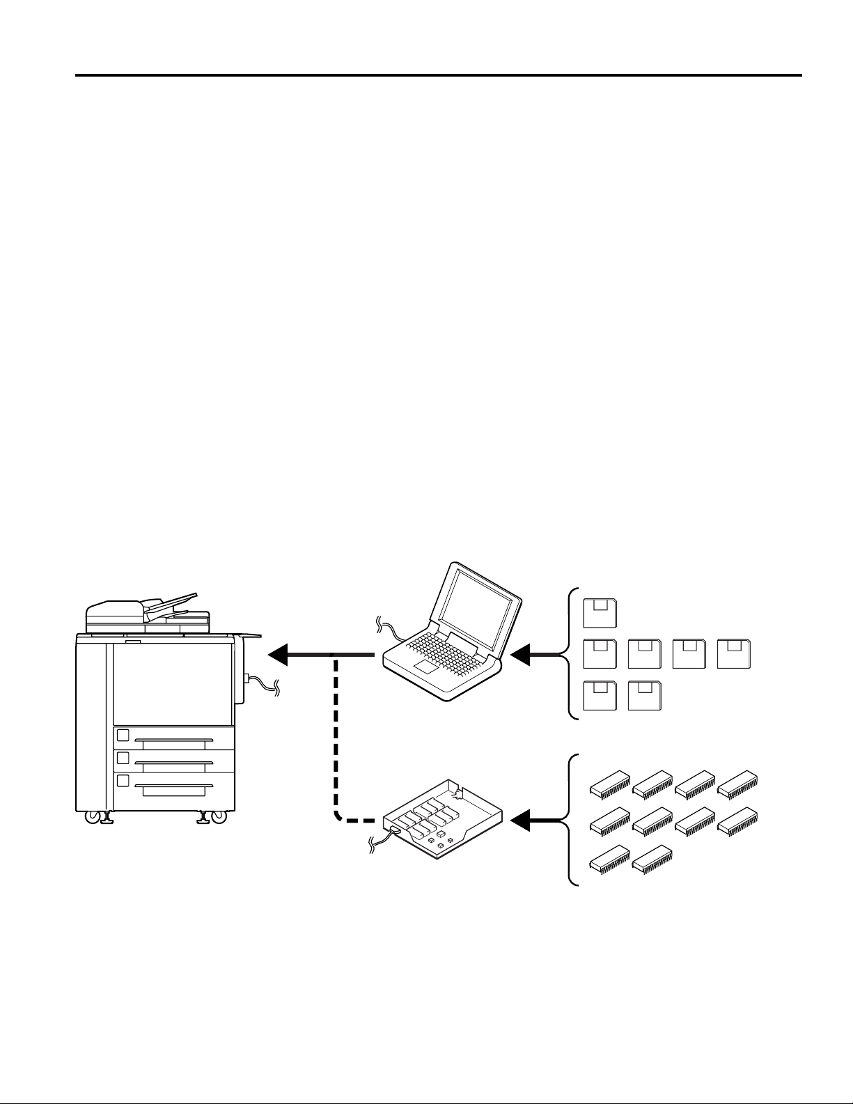
INTRODUCING ISW
ISW (In-System Writer) is a process of updating the control programs stored in flash ROM mounted on various control
boards in a Konica digital copier without isolating the boards or the ROM from the copier. Running ISW enables you to
upgrade control programs without replacing the boards and maintain the boards during their replacement.
Tools available f or running ISW include ISW Trns (PC software), which connects a personal computer (PC) to the digital
copier, and ISW T ool, which is a dedicated tool using EPR OM.
These tools can be plugged into the ISW connector of the digital copier to update the control programs in flash ROM
assembled in the copier unit and its options.
WHAT IS ISW TRNS (ISW TRANSFER)?
ISW Trns is a software utility that runs under Windows to re write the flash ROMs in the copier. Connect the copier to a
personal computer using a parallel cable and ex ecute this utility to rewrite the flash ROMs with data transferred from the
personal computer.
WHAT IS ISW Tool?
ISW Tool is a ROM writer device dedicated for rewriting the flash ROMs in the copier without using a personal computer.
Attach EPROMs to the ISW Tool to rewrite the flash ROMs with data transferred from the EPROMs.
Parallel
cable
Copier
Windows PC
ISW T ool
3
Page 12

ISW
SPECIFICA TIONS
[1] ISW Trns (PC Software)
1. ISW Trns disk organization
• Setup disk: 2 disks
• Update disk: Dependent on the copier.
2. Software environment
• OS: Windows 95/98
• CPU: Pentium 75 MHz or faster
• RAM: 16 MB or more
• Hard disk 100 MB or more
space:
• Others: PC supporting a parallel (printer)
interface port
3. Transfer time
Dependent on the copier and personal computer.
4. Prerequisites to running ISW
• Personal computer (PC):1 unit
IBM compatible (PC/A T with a D-sub 25 pin
Parallel (printer) interface)
• ISW Trns setup disk: 2 disks
• Update ROM data: Dependent on the
copier.
• Parallel cable: 1 (Anphenol 36-pin-D-sub 25-pin;
Centronics; within 2 meters in length)
Windows 95/98 is a registered trademark of Microsoft
Corporation.
Pentium is a registered trademark of Intel Corporation.
4
Page 13
ISW
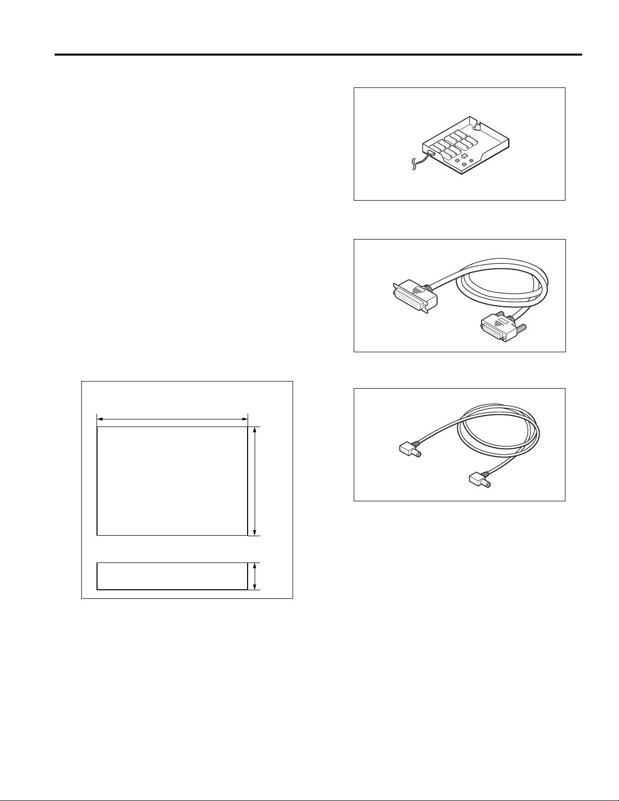
[2] ISW Tool (Dedicated Tool)
1. ISW EPROM configuration
Dependent on the copier.
Refer to the service manual supplied with the copier.
2. EPROM specifications
4M bits
M27C4001-12F1 (SGS-THOMSON)
equivalent: Part No. 943010900
3. Transfer time
Dependent on the copier.
4. Mechanical specifications
Input power requirement: 5 VDC (supplied from the
copier)
Maximum power consumption: 2.5 W or less
Weight: About 1 lb. (without EPROM installed)
Physical dimensions:
5. Operating environment
Same as the operating environment for the copier unit.
6. Prerequisites to running ISW
• ISW Tool: ............................................. 1 pc.
• Parallel interface cable: ........................1 pc.
9.5
Unit: inches
(approx.)
7.7
• Power cable: ........................................1 pc.
7. Safety
Use of this equipment may give electromagnetic
interference to surrounding devices.
1.7
Note: Specifications are subject to change without
notice.
5
Page 14
ISW
UPDATING WITH ISW Trns
[1] Setting Up ISW Trns
1. Installing the application program
Install the ISW Trns on the PC.
Step Procedure
1 Boot the PC.
2 Mount setup disk 1 on the PC and
double-click the [Setup.e xe] icon to start
the installer.
Caution:If an old version ISW Trns
program is present, uninstall it
first, then start the setup
operation.
3 [ISW Trns setup window]
Confirm the installation folder as
instructed by on-screen guidance and
click Next.
Note 1: By default, the program installs
in [C:\Program Files\konica\
ISWTrns].
Note 2: To change the installation
folder, click Browse and type
a new folder name.
4 [Program folder confirmation window]
Confirm the ISW Trns program
installation folder as instructed by onscreen guidance and click Next.
Note 1: By default, the ISW Trns
program installs in [ISWTrns].
Note 2: To change the installation
folder , either type a new f older
name or select one from the
list of existing folders on
display.
5 [Next disk insertion request window]
Mount setup disk 2 as instructed by onscreen guidance and click OK.
6 [Information dialog box]
Click OK as instructed by on-screen
guidance.
Note: This procedure will add an ISW
Trns icon to the Start menu.
7 [Setup completion window]
Click Complete as instructed by onscreen guidance.
8 The ISW Trns install exits automatically .
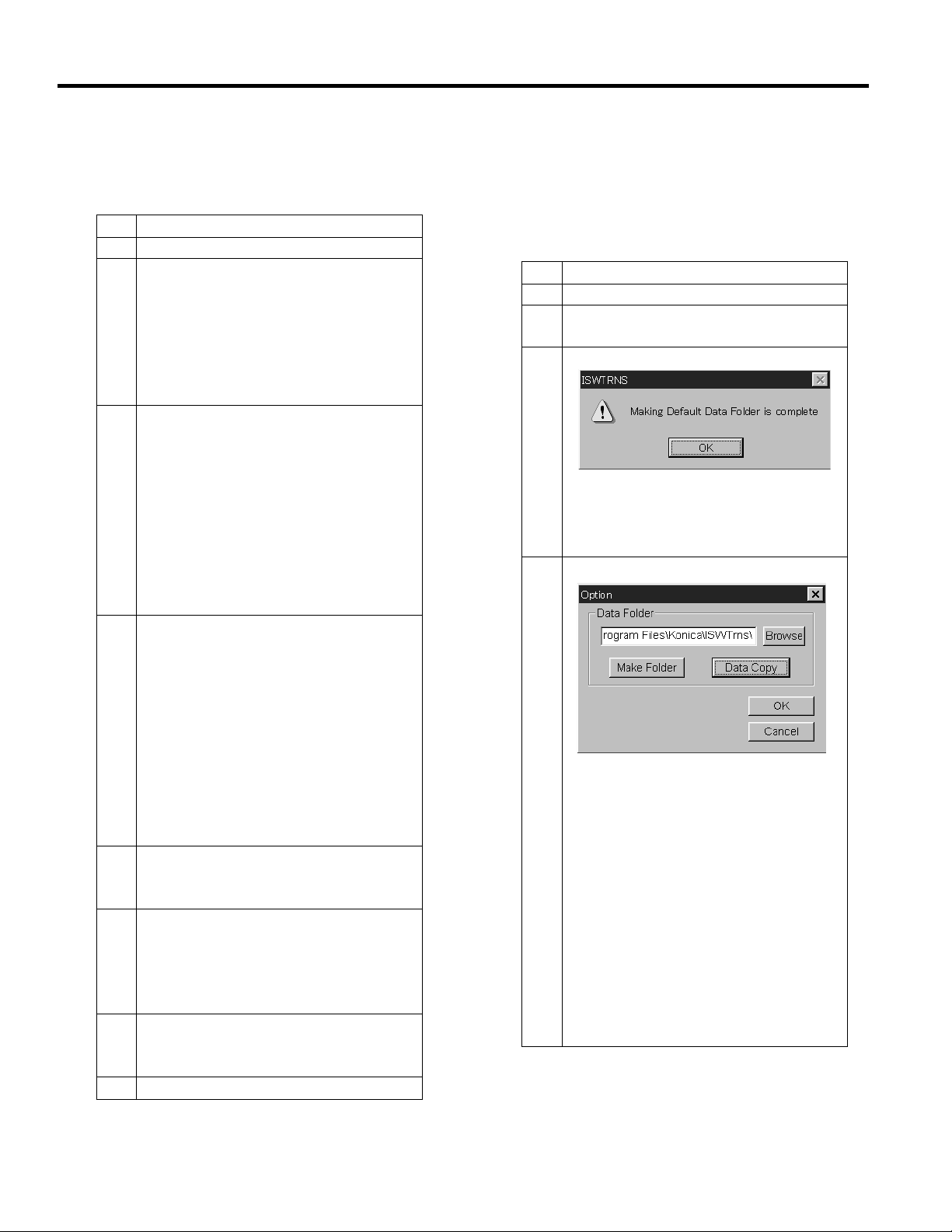
2. Setting up ISW Trns
When the ISW Trns program has been installed on
the PC, run it to set up a folder in which the transfer
file (update data) is stored. When this setting
completes, the ISW Trns program is ready to run.
Step Procedure
1 Boot the PC.
2 Select [ISW Trns] from the start menu
to run the ISW Trns program.
3 [ISW Trns dialog box]
Click OK to set up a folder in which the
transfer file (update data) is stored.
Note: This dialog box will not appear
when ISW Trns is run next time.
4 [Option window]
Set up a folder in which the transf er file
(update data) is stored and click Make
Folder.
Note 1: By default, the folder in which
the ISW Trns program has
installed (C:\Program
Files\konica\ISWTrns) has
been set up as a storage folder
(data folder).
Note 2: To change the storage folder,
click Browse and select a new
folder or type its full-path name
directly in the edit box.
6
Page 15

Step Procedure
Note 3: Clicking Make Folder will
create the following hierarchy
of folders branching off from
the new storage folder:
ISW
5. [Option window]
Click OK.
Note: This procedure will save the
data folders created in Step 4
to the INI file for the ISW Trns
program.
6 [ISW Trns main window]
The ISW Trns main window opens.
7
Page 16

ISW
3. ISW Trns Main Window Overview
The ISW Trns program, when run, comes up with the ISW T rns main window . The ISW T rns main window lets you
select, verify, and transfer a transfer file (update data) and display information in it. A detailed description of its
functions follows:
1. Select Type frame
Select conditions for a transfer file (update data). When you select all the four combo boxes, folder t is set up on
the basis of the information set in the INI file.
The settings of the combo boxes selected are saved to the ISW Trns.INI file when you click File Send. The ISW
Trns program comes up with the ISW Trns main window prefilled with these combo box settings when runs next
time.
2. Version selection frame
This frame lets you select which version of a transfer file you want transmitted when more than one version is
stored in a single folder.
3. Send file information frame
List the files that are transferred actually on the basis of the information specified in frames 1 and 2. Click File
Check to view a checksum of each file and its consistency (OK, NG or ??).
8
Page 17

Data sources appearing in the detailed file information list
Display title ORIGINAL (Batch data) DIVIDE (Divided data)
File Name
File Date Date of the version selection file Date of the version selection file
File Time Time of the version selection file Time of the version selection file
File Size
ROM Version Footer information Footer information (last file)
SP ROM Footer information Footer information (last file)
V ersion 7033/7040 imaging control; 7033/7040 imaging control;
Message For dev elopment use For dev elopment use
Conversion
Machine Name Header information + INI file Header information + INI file
Country Combo box display Combo box display
Board Name Header information + INI file Header information + INI file
Data Format Header information (Binary) Header information (Binary)
File name of the version selection file File name of the version selection file
File size of the version selection file File size of the version selection file
7033/7040 imaging control; 7033/7040 imaging control;
faxes are not displa yed faxes are not displayed.
faxes are not displa yed faxes are not displayed.
*In a 7075 batch transfer, the board type in the *In a 7075 batch transfer, the board type in the
leading part is displayed (for example, c1 is leading part is displayed (for example, c1 is
displayed for c1 to c5). displayed for c1 to c5).
ISW
4. File Status frame
View detailed information about the version file as
it is selected in 6. The table below presents
differences in the ways transfer files are displayed
according to their data distribution types. The files
in this list are sorted by name. When the list
opens, the last display item in the list is
preselected. Change the choice to establish the
version of transfer files to transmit.
5. Browse Version File button
Click Browse button to open the folder selection
window and select a folder for 5.
6. Send file information display list
List the names of files that are actually transmitted
when a version file is selected in 6. A count of the
number of files that are actually transmitted is
indicated in a checksum file attached to each
transfer file (write data). If not all the transfer files
are stored in folder t or if extra files are included in
it, the error message “Send files not found or invalid
file name in the folder” is displayed. This check is
not made, however, on 7033 and 7040 transfer files
that do not have a checksum file.
Clicking the File Check button in 9 calculates a
checksum of the display files as a whole and
compares it with the checksum stored in the
checksum file (*.SUM) attached to the transfer file
(write data), displaying the result of that
comparison.
7. File Check button
Click this button when send files are listed in the
Send File Info list in i, and a file checksum of the
transfer files displayed (file checksum) is calculated
and attached to each file. Further, the calculated
checksum is compared with the checksum storage
file (*.SUM) attached to the transfer file (write data)
to display the result of the comparison in the
following format:
[OK] = Matched
[NG] = Unmatched
[??] = Checksum file (*.SUM) not found
(This is displayed if it is of 7033 and
7040.)
8. File Send Button
Perform transmission of transfer files
9
Page 18

ISW
4. Parallel port setup
If a parallel data transfer is to be executed with the
ISW Trns program, the ECP mode setting of the PC
parallel port should be cleared. ISW Trns does not
support parallel data transfers. If a parallel data
transfer is launched with the PC set in ECP mode,
the transfer could be aborted by an error occurring in
between. It would be necessary , therefore, to disable
ECP mode before run ISW Trns on a PC with the
ECP setting.
Instructions on how to disable ECP mode are given
below.
Step Procedure
1 Boot the PC.
2 Open the System icon in the Control
Panel and click the De vice Manager tab.
Then, search for LPT1 in Po rts (COM/
LPT1).
Note 1: If LPT1 appears as “ECP
Printer Port (LPT1),” then it is
an ECP port.
Note 2: If LPT1 appears as “Printer
Port (LPT1), ” then it is a regular
parallel port.
3 With an ECP printer port, change the
BIOS setting of the PC to disable the
ECP port.
Note: Because the BIOS setting
depends on the PC, check with
your system administrator on
how to disable ECP mode.
4 When the BIOS change is complete,
open the System icon in the Control
panel and change the parallel port driver.
5 Run a send test to verify the successful
operation.
Note: If a transfer succeeds on one
copier model, then transfers
would be successful on all
models.
10
Page 19

ISW
[2] Copying Transfer Data (Update Data)
Run the ISW Trns program to copy transfer data
(update data) to the PC.
Step Procedure
1 Boot the PC.
2 Select ISW Trns from the Start menu to
run the ISW Trns program.
3 Click the Option menu.
4 [Option window]
Click Data Copy.
5 [File Copy window]
Mount an update disk on the PC and
click Browse.
6 Select the folder on drive A that contains
the transfer file (update data) as a source
file.
Note 1: The selected folder is
displayed in the upper section
in the Original Files field.
Note 2: The transfer files (update data)
that are stored in the selected
folder are displayed in the
lower section in the Original
Files field.
7 Select the transfer files (update data) you
want copied from the lower section in
the Original Files field.
Note 1: You can select multiple
transfer files (update data).
Note 2: To copy all the files (update
data) displayed, skip this step
to go to Step 8 directly.
Step Procedure
8 Click Copy to copy the selected transfer
files (update data) to the folder created
at ISW Trns setup.
Note 1: To copy all the files (update
data) displayed in the Original
Files field, click Copy All,
instead of Copy.
Note 2: The folder name created at
ISW Tr ns setup is displayed
above the Copied File field.
Note 3: The transfer files that have
been copied successfully so
far are listed in full-path name
in the lower part of the Copied
File list view.
The transfer files that ha ve not
been copied successfully are
listed in the Failed to Copy
Files list view .
Causes of copy errors:
1. A file with the same name
existed and the O/W
(overwrite) check box was
not checked.
2. The storage destination
folder could not be found.
3. Attempted to overwrite an
overwrite protected file.
Note 4: T o update existing transf er files
(update data), check the O/W
(overwrite) check bo x.
9 When the copying completes, click
Refresh.
10 If more update disks are inv olved, repeat
Steps 5 to 9.
11 Click Cancel to return to the option
window.
12 [Option windo w]
Click OK.
11
Page 20

ISW
[3] Connecting
Connect a parallel interface cable to the copier.
Prerequisites to cabling are:
• A PC to which transfer files (update data) have been
copied.
• A parallel interface cable (Anphenol 36-pin-D-sub
25-pin)
Note: For instructions on how to connect a parallel
interface cable to the copier , ref er to the ISW
section of the service manual supplied with
the copier.
Step Procedure
1 Turn off the copier main switch.
2 Turn off the PC power switch.
3 Connect the PC parallel port and the
copier ISW connector with a parallel
interface cable.
PC
Parallel
(printer)
interface port
ISW connector
(36-pin)
Centronics cable
[4] Updating
1. Update operation overview
Follow the steps below to update the ROM data on
each control board using ISW Trns. For more
operational details, see the relevant parts of this
section.
Step Procedure
1 Check the ROM version of the copier
before proceeding with updating. (See
2, “Checking the ROM version of the
copier (before updating).”)
2 Run the ISW Trns program. (See 4,
“Running ISW Trns.”)
3 Set the copier in ISW receive mode.
(See 3, “Preparing the copier to
transfer.”)
4 Select conditions for transfer files
(update data) with ISW Trns. (See 5,
“Selecting transfer file (update data)
conditions.”)
5 Select a version of transfer files (update
data) with ISW Trns. (See 6, “Selecting
a version of transfer files (update data).”)
6 Verify the transfer files (update data)
selected with ISW Trns. (See 7, “V erifying
transfer files (update data). ”
7 Transmit the transfer files (update data)
with IWS Trns. (See 8, “Transmitting
transfer files (update data).”)
8 To update ROM data on more control
boards, repeat Steps 3 to 7.
9 Exit the ISW Trns program. (See 9,
“Exiting ISW Trns. ”)
10 V erify the ROM v ersion of the copier after
updating. (See 10, “Verifying the ROM
version of the copier (after updating).”)
12
Page 21

ISW
2. Checking the ROM version of the copier (before
updating)
Before updating ROM data, check the ROM version
of the existing control program in the 25 mode.
Step Procedure
1 Turn OFF the copier main switch.
2 Turn ON the copier main switch while
holding down the copy count setup
buttons 2 and 5, to enable 25 mode.
3 [25 mode menu window]
Check the ROM version b y following the
copier-specific procedure.
Note: For operating instructions,
refer to the Adjustment section
of the service manual supplied
for the copier .
3. Preparing the copier to transfer.
Start the copier with 25 mode enabled to put the copier
into ISW transfer wait state.
Step Procedure
1 Turn OFF the copier main switch.
2 Turn ON the copier main switch while
holding down the copy count setup
buttons 2 and 5, to enable 25 mode.
3 [25 mode menu window]
Put the copier into ISW transfer wait
state by following the copier-specific
procedure.
Note 1: “ISW transfer wait state” is the
state of the copier with the
START
key being shown in the
display area.
Note 2: For operating instructions,
refer to the Adjustment section
of the service manual supplied
for the copier .
4. Running ISW Trns.
Run the ISW Trns program.
Step Procedure
1 Boot the PC.
2 Select ISW Trns from the Start menu and
run the ISW Trns program.
13
Page 22

ISW
5. Selecting transfer file (update data) conditions
Select various conditions for selecting the transfer
files (update data) in the ISW Trns main window.
Conditions to select are:
• (Machine) The name of the model on which ROM
data is updated
• (Country) The destination of the transfer files
(update data)
• (Board) The name of the board on which ROM data
is updated
• (Divide) The type of the transfer files (update data)
Step Procedure
1 [ISW Trns main window]
In the ISW Trns main window, click
in the [Machine] field in [Select Type] and
select the name of the model on which
to update ROM data from the pulldown
menu.
Step Procedure
3 In the ISW Tr ns main window, click
in the [Board] field in [Select Type] and
select the name of the board on which
to update ROM from the pulldown menu.
4 In the ISW Trns main window, click
in the [Divide] field in [Select Type] and
select a method of dividing the transfer
files (update data) from the pulldown
menu.
2 In the ISW Trns main window, click
in the [Country] field in [Select T ype] and
select the destination of the transfer files
(update data) from the pulldown menu.
Note 1: Normally, select ORIGINAL as
the method of division.
Note 2: Select DIVIDED for large ROM
data (e.g. for Main Control
Unit), that is divided into
several files (extension
.001.b01, etc.) to be stored to
several floppy disks for
distribution.
14
Page 23

ISW
6. Selecting a version of transfer files (update
data)
When a transfer file (update data) has been chosen
to meet a given set of conditions, it may be available
in multiple versions. Here, select a particular version
of a transfer file (update data) for use in the actual
data transfer.
Step Procedure
1 [ISW Trns main window]
In the ISW Trns main window, select a
transfer file (update data) of the v ersion
that is used in the actual data transfer
from among the files listed in the [File]
field in [V ersion].
Note: The version of a transfer file
(update data) can be determined
from its file name.
Example:
26nac001AAAA.b01 .. V ersion 1
26nac002AAAA.b01 .. V ersion 2
2 The target file (update data) may not be
shown in the [File] field in [Version], if it
exists in a folder different from the data
folders set in the Option screen. Click
Browse and find the appropriate file to
select.
7. Ver ifying transfer files (update data)
Once a particular version of a transfer file (update data)
is selected, the transfer files (update data) that are
transmitted actually are listed in [Send File Infor] in
the ISW Trns main window . V erify the validity of the
transfer files (data) for transfer.
Step Procedure
1 [ISW Trns main window]
In the ISW Trns main window, click File
Check in [Send File Infor].
2 Check to see if OK appears in the [File
Sum] field in [Send File Infor] in the ISW
Trns main window.
Note 1: A file that is labeled NG is
inappropriate as a transfer file
(update data). Try to copy the
file again. If you can not
succeed to copy it again, the
original file may be corrupted.
Note 2: Transfer files (update data)
may be marked ?? when
enough information is not
available to v erify their validity .
When a transfer file is labeled,
check if the checksum file
(*.sum) was copied correctly.
Transfer files (update data) is
always marked ?? when it is
for 7030 and 7040. In this
case, this is not an copy error .
Note: Clicking Browse will open the
Select File window .
15
Page 24

ISW
8. Transmitting transfer files (update data)
When transfer files (update data) are established, run
a data transfer to the copier.
Step Procedure
1 Press the
it is in ISW transfer wait state .
Note 1: The
2 [ISW Trns main window]
Click File Send in [Send File Infor] in the
ISW Trns main window.
3 Transfer files (update data) are
transmitted to the copier.
Note 1: While data is being transferred
Note 2: ISW Trns produces an
Note 3: If a data transfer is aborted
4 To update ROM data on more control
boards, repeat the step in 5, “Selecting
transfer file (update data) conditions,” to
8, “Transmitting transfer files (update
data).”
START
key on the copier while
START
key is displayed
in the display area on the
copier.
to a copier, an LED or indicator
flashes to indicate a data
transfer in progress. The
mode of such indication varies
from one copier to another.
indication to designate a data
transfer in progress.
due to any trouble occurring
with the copier or ISW Trns,
turn the copier main switch
OFF, then ON to retry the data
transfer by ISW Trns.
In this case, a condition
indication and necessary
operation vary depending on
each model. Please refer to
service manual for the copier .
9. Exiting ISW Trns.
When the update of the ROM data on the control
boards completes, exit the ISW Trns program.
Step Procedure
1 Exit the ISW Trns program.
2 Turn OFF the PC.
3 Turn OFF the copier main switch.
4 Disconnect the parallel interface cable
from the PC and the copier.
Note: Turn OFF the PC and copier
before disconnecting the parallel
interface cable from them.
10. Verifying the ROM version of the copier (after
updating)
When the update of the ROM data completes, verify
the ROM version of the control program in the 25 mode.
Step Procedure
1 Turn OFF the copier main switch.
2 Turn ON the copier main switch while
holding down the copy count setup
buttons 2 and 5, to enable 25 mode.
3 [25 mode menu window]
Check the ROM version b y following the
copier-specific procedure.
Note: For operating instructions,
refer to the Adjustment section
of the service manual supplied
for the copier .
16
Page 25

UPD A TING WITH ISW TOOL
[1] Kinds of Updating
1. Upgrading program ROM
Though ISW T ool was originally developed as a dedicated 7033/7040 tool, its program ROM is upgraded to make it
universally work with copiers of 7033/7040 later models.
This upgrade supports all types of digital copiers with ISW support.
Note: If ISW Tool is already available at a service site as a 7033/7040 tool, its program ROM must be upgraded.
2. Kinds of operation
ISW T ool requires program ROM to be updated in different ways among dif ferent copier types, namely , T ype A, Type
B, and Type C.
Note: See the section relevant to your copier model when running ISW Tool to update ROM.
Note 1: Up to 12 ROMs can be mounted on ISW Tool concurrently. If a control board has more than 12 ROMs
mounted on it, data transfers to them must be run in two or more installments.
Note 2: For type C model, only three types of ROM can be mounted even if ISW T ool has enough ROM soc k ets
availab le, hence oper ation is diff erent from that for others when tr ansmitting data.
ISW
Copier model Control board
Type A Main control board 1 • ROMs on all control boards can be mounted on ISW
(Example: Imaging control board 2 Tool concurrently.
7033/7040) Fax control board 3
T ype B Main control board 1
(Example: Imaging control board 2
7020) Fax control board 3
ADF control board 4
FNS control board 5
Type C Printer control board Depends on the • ROM mount check is displayed using a board code
(Example: Operating control board mount order stored in the ROM data. This change enables to
7075 and after.) Graphic control board correspond with any additional models in future
ADF control board without depending on models.
VIF control board • Up to three types of ROM can be mounted on ISW
LED1 data transmission F
start number
eature
• Supporting control boards that carry 12 or more ROMs
(Note 1).
Tool concurrently. (Note 2)
• When transmitting update data, specify the target
ROM not by the ROM specific value but by the
mounted order number selectable from among 7
through 9.
17
Page 26

ISW
[2] Setting Up ISW Tool
1. Detach the cover
Remove four clamping screws to detach the ISW T ool
cover.
Note: Use ISW Tool with the cover out of position.
18
Page 27

2. Names and functions of ISW Tool components
ISW
7
5
No. Name Function
1 Status indication Lamp (LED1) Indicates states of power continuity , data update , and errors.
2 RESET switch Press to clear an error as it occurs and reset ISW Tool.
3 MODE switch Selects control boards to update.
4 ST AR T/STOP switch Starts or stops updating.
5 ISW connector Connects ISW Tool to a copier using a parallel interface cable.
6 Power connector Supplies power to ISW Tool.
7 ROM sockets 1-12 Hold update ROMs.
8 ROM clamping lever Clamps update ROMs mounted in the sockets .
9 Cover Close this cover when storing or relocating ISW Tool.
10 Cover clamping screw Clamps the cover (f our scre ws).
8
3
4
6
12
10
9
10
19
Page 28

ISW
[3] Connecting
Turn OFF the copier power switch, then connect the
copier and ISW T ool with a parallel interface cable.
Prerequisites to making this connection are:
• An ISW T ool uncovered
• A parallel interface cable (bundled with ISW T ool)
• A power cable (bundled with ISW T ool)
• An update ROM set (EPROM)
Note: For instructions on how to connect a parallel
interface cable and a power cable to the
copier, ref er to the ISW section of the service
manual supplied for the copier .
Step Procedure
1 Turn OFF the copier main switch.
2 Connect the ISW connector of ISW Tool
and that of the copier with the parallel
interface cable. Plug the ISW Tool's
power cable connector into the DC5V
jack of the copier .
Example:
Power cable
ISW Tool
ISW connector
(25-pin)
ISW cable
(parallel interface
cable)
ISW connector
(36-pin)
20
Page 29

ISW
[4] Updating Type A Models
This ROM data update operation applies to 7030 and
7040 model copiers.
1. Kinds of transfer data ROMs and their status
indications
The table below lists the kinds and quantities of ROMs
available for Type A models. When ROMs are mounted
on ISW Tool and the power cable is connected to it,
ISW Tool starts checking the ROMs mounted. The
status indicating lamp (LED1) represents the status
of checking, giving you a visual recognition of for which
control board the ROMs mounted are used.
2. Update operation summary
Control Quantity of Status LED 1 data
board R O M s indication transmission
name start number
Main
control 8 1
board
Step Procedure
4 Connect the power cable to ISW T ool and
identify the ROMs mounted. (See 6,
“Checking ROMs mounted. ”)
5 T ransmit the ROM data mounted on ISW
Tool to the copier. (See 7, “Transmitting
update data. ”)
6 Disconnect the parallel interface cable
and the power cable to end the update
operation. (See 8, “Ending the update
operation.”)
7 Verify the ROM v ersion of the copier after
updating. (See 9, “Verifying the ROM
version of the copier (after updating).”)
3. Checking the ROM version of the copier (before
updating)
Before updating ROM data, check the ROM version
of the existing control program in the 25 mode.
Imaging
control 2 2
board
Sequence the procedural steps below to update ROM
data on the control boards with ISW Tool. For more
operational details, see the relevant parts of this
section.
Step Procedure
1 Check the ROM version of the copier
before proceeding with updating. (See
3, “Checking the ROM version of the
copier (before updating).”)
2 Set the copier in ISW receive mode.
(See 4, “Preparing the copier to
transfer.”)
3 Mount ROMs on ISW Tool. (See 5,
“Mounting ROMs.”)
Step Procedure
1 Turn OFF the copier main switch.
2 Turn ON the copier main switch while
holding down the copy count setup
buttons 2 and 5, to enable 25 mode.
3 [25 mode menu window]
Check the ROM version b y following the
copier-specific procedure.
Note: For operating instructions,
refer to the Adjustment section
of the service manual supplied
for the copier .
21
Page 30

ISW
4. Preparing the copier to transfer.
Start the copier with 25 mode enabled to put the copier
into ISW transfer wait state.
Step Procedure
1 Turn OFF the copier main switch.
2 Turn ON the copier main switch while
holding down the copy count setup
buttons 2 and 5, to enable 25 mode.
3 [25 mode menu window]
Put the copier into ISW transfer wait
state by following the copier-specific
procedure..
Note 1: “ISW transfer wait state” is the
state of the copier with the
START
key being shown in the
display area.
Note 2: For operating instructions,
refer to the Adjustment section
of the service manual supplied
for the copier .
5. Mounting ROMs
Mount control board ROMs in the ISW Tool ROM
sockets.
Note 1: ISW Tool ROM sockets numbered 1 to 12
are available . ROMs must be mounted in
groups by each control board.
Note 2: Mount each ROM with pin 1 aligned with
socket pin 1.
6
5
4
3
12
11
10
LED1
RESET
9
SW
1 pin
2
1
EPROM
8
MODE
SW
7
START
/STOP
SW
22
Page 31

ISW
6. Checking ROMs mounted
View the status indicating lamp (LED1) to identify for
which control board the ROMs mounted on ISW T ool
are used.
Note: For the indications of the status indicating
lamp (LED1) associated with the control
boards, see 1, “Kinds of transf er data R OMs
and their status indications.”
Step Procedure
1 Connect the power cable to the ISW T ool
power connector .
2 The status indicating lamp (LED1)
produces indications associated with the
ROMs mounted in sequence following
an initial indication. Make sure that it
displays 0 in the end to verify a normal
state.
Example: Indications produced by
LED1 when ROMs are
mounted in the following
order.
1.Main control board
2.Imaging control board
Step Procedure
2 Press the ISW Tool MODE switch to
display the number associated with each
control board on which ROM data is
updated on the status indicating lamp
(LED1).
Note: For type A model, LED
transmission number indications
are fixed, and the order of the
ROMs mounted in the sockets
is irrelevant.
3 Press the ISW Tool ST AR T/STOP s witch
to transmit update data to the copier.
Note 1: While data is being transferred
to a copier, an LED or indicator
flashes to indicate a data
transfer in progress. The
mode of such indication varies
from one copier to another.
Note 2: ISW Tool produces the
following indications
alternately to designate a data
transfer in progress:
Main control
board
Initial
indication
7. T ransmitting update data
Run a data transfer to the copier.
Step Procedure
1 Press the
it is in ISW transfer wait state .
Note 1: The
Note 2: The control board on which
START
key on the copier while
START
in the display area on the
copier.
ROM data is to be updated is
preselected before the
key is pressed. For operating
instructions, refer to the
Adjustment section of the
service manual supplied for
the copier.
Imaging control
board
key is displayed
OK
START
Note 3: If a data transfer is aborted
due to any trouble occurring
with the copier or ISW Tool,
turn the copier main switch
OFF, then ON to retry the data
transfer by ISW Tool. In this
case, a condition indication
and necessary operation vary
depending on each model.
Please refer to service manual
for the copier .
4 To update ROM data on more control
boards, repeat the step in 1 to 3.
23
Page 32

ISW
8. Ending the update operation
When the update of the ROM data on the control
boards completes, disconnect the parallel interface
cable and the power cable to end the update operation.
Step Procedure
1 Turn OFF the copier main switch.
2 Disconnect the parallel interface cable
and the power cable from ISW Tool and
the copier.
Note: Turn OFF the copier before
disconnecting the parallel
interface cable from it.
9. Ver ifying the ROM version of the copier (after
updating)
When the update of the ROM data completes, verify
the ROM version of the control program in the 25 mode.
Step Procedure
1 Turn OFF the copier main switch.
2 Turn ON the copier main switch while
holding down the copy count setup
buttons 2 and 5, to enable 25 mode.
3 [25 mode menu window]
Check the ROM version b y following the
copier-specific procedure.
Note: For operating instructions,
refer to the Adjustment section
of the service manual supplied
for the copier .
[5] Updating Type B Models
This ROM data update operation applies to the 7020
copiers.
1. Kinds of transfer data ROMs and their status
indications
The table below lists the kinds and quantities of ROMs
available for Type B models. When ROMs are mounted
on ISW Tool and the power cable is connected to it,
ISW Tool starts checking the ROMs mounted. The
status indicating lamp (LED1) represents the status
of checking, giving you a visual recognition of for which
control board the ROMs mounted are used.
Quantitiy of ROMs are subject to change.
Control Quantity of Status LED 1 data
board R O Ms indication transmission
name start number
Main
control 1 7 1
board
Imaging
control 2 2
board
ADF
control 1 4
board
FNS
control 1 5
board
24
Page 33

ISW
2. Update operation summary
Sequence the procedural steps below to update ROM
data on the control boards with ISW Tool. For more
operational details, see the relevant par ts of this
section.
Step Procedure
1 Check the ROM version of the copier
before proceeding with updating. (See
3, “Checking the ROM version of the
copier (before updating). ”)
2 Set the copier in ISW receive mode.
(See 4, “Preparing the copier to transfer . ”)
3 Mount ROMs on ISW Tool. (See 5,
“Mounting update ROMs. ”)
4 Connect the power cable to ISW T ool and
identify the ROMs mounted. (See 6,
“Checking ROMs mounted. ”)
5 T ransmit the ROM data mounted on ISW
Tool to the copier. (See 7, “Transmitting
update data. ”)
6 With a ROM set containing 12 or more
control board ROMs, return to step 3 and
mount the rest of ROMs, repeating up to
Step 5.
7 T o transmit more control board ROM data
to the copier, repeat Steps 3 to 5.
8 Disconnect the parallel interface cable
and the power cable to end the update
operation. (See 8, “Ending the update
operation.”)
9 Verify the R OM version of the copier after
updating. (See 9, “Verifying the ROM
version of the copier (after updating). ”)
3. Checking the ROM version of the copier (before
updating)
Before updating ROM data, check the ROM version
of the existing control program in the 25 mode.
Step Procedure
1 Turn OFF the copier main switch.
2 Turn ON the copier main switch while
holding down the copy count setup
buttons 2 and 5, to enable 25 mode.
3 [25 mode menu window]
Check the ROM version by following the
copier-specific procedure.
Note: For operating instructions, refer
to the Adjustment section of
the service manual supplied for
the copier.
4. Preparing the copier to transfer.
Start the copier with 25 mode enabled to put the
copier into ISW transfer wait state.
Step Procedure
1 Turn OFF the copier main switch.
2 Turn ON the copier main switch while
holding down the copy count setup
buttons 2 and 5, to enable 25 mode.
3 [25 mode menu window]
Put the copier into ISW transfer wait
state by following the copier-specific
procedure.
Note 1: “ISW transfer wait state” is the
state of the copier with the
START
key being shown in the
display area.
Note 2: For operating instructions, refer
to the Adjustment section of
the service manual supplied for
the copier.
25
Page 34

ISW
5. Mounting update ROMs
Mount control board ROMs in the ISW Tool RO M
sockets.
Note 1: ISW Tool ROM sockets numbered 1 to 12
are available. ROMs must be mounted in
groups by each control board.
Note 2: Have the power cable disconnected from
ISW Tool before mounting R OMs on it.
Note 3: With a ROM set containing 12 or more
control board ROMs, mount ROM1 to
ROM12 and transmit data. Then, mount
ROM13 and later ROMs in the ROM
sockets from their top and then transmit
data again. LED on the copier panel lights
while mounting ROMs, and set to the
standby for second data transf er .
Note 4: Mount each ROM with pin 1 aligned with
socket pin 1.
6. Checking ROMs mounted
View the status indicating lamp (LED1) to identify for
which control board the ROMs mounted on ISW Tool
are used.
Note: For the indications of the status indicating
lamp (LED1) associated with the control
boards, see 1, “Kinds of transfer data ROMs
and their status indications.”
Step Procedure
1 Connect the power cable to the ISW Tool
power connector .
2 The status indicating lamp (LED1)
produces indications associated with the
ROMs mounted in sequence following an
initial indication. Make sure that it
displays 0 in the end to verify a normal
state.
Example: Indications produced by LED1
when ROMs are mounted in
the following order .
1.Imaging control board
2.ADF control board
3.FNS control board
1 pin
6
5
4
3
2
1
EPROM
12
11
10
Imaging control
board
Initial
indication
LED1
RESET
9
8
MODE
7
SW
SW
START
/STOP
SW
ADF control
FNS control
board
OK
board
26
Page 35

7. Transmitting update data
Run a data transfer to the copier .
Step Procedure
1 Press the
it is in ISW transfer wait state.
Note 1: The
Note 2: The control board on which
2 Press the ISW Tool MODE switch to
display the number associated with each
control board on which ROM data is
updated on the status indicating lamp
(LED1).
Note 1: For type B model, LED
Note 2: With a ROM set containing 12
START
key on the copier while
START
in the display area on the
copier.
ROM data is to be updated is
preselected before the
key is pressed. For operating
instructions, refer to the
Adjustment section of the
service manual supplied for
the copier.
transmission number
indications are fixed, and the
order of the ROMs mounted in
the sockets is irrelevant.
or more control board ROMs,
LED1 must display ‘1’ for both
the first and second runs.
key is displayed
START
ISW
Step Procedure
3 Press the ISW Tool START/ST OP switch
to transmit update data to the copier.
Transfer files (update data) are
transmitted to the copier.
Note 1: While data is being transferred
to a copier, an LED or indicator
flashes to indicate a data
transfer in progress. The mode
of such indication varies from
one copier to another.
Note 2: ISW Tool produces the
following indications alternately
to designate a data transfer in
progress:
Note 3: If a data transfer is aborted due
to any trouble occurring with
the copier or ISW Tool, turn the
copier main switch OFF, then
ON to retry the data transfer
by ISW Tool. In this case, a
condition indication and
necessary operation vary
depending on each model.
Please refer to service manual
for the copier .
4 To transfer control board data on more
control boards mounted on ISW Tool,
repeat Steps 1 to 3.
5 To transmit the rest of ROM data in a
ROM set containing 12 or more control
board ROMs or to transmit additional
ROM data not mounted on ISW Tool,
repeat 5, “Mounting update ROMs” to
Step 4 in 7, “Transmitting update data.”
27
Page 36

ISW
8. Ending the update operation
When the update of the ROM data on the control
boards completes, disconnect the parallel interface
cable and the power cable to end the update operation.
Step Procedure
1 Turn OFF the copier main switch.
2 Disconnect the parallel interface cable
and the power cable from ISW Tool and
the copier.
Note: Turn OFF the copier before
disconnecting the parallel
interface cable from it.
9. Verifying the ROM version of the copier (after
updating)
When the update of the ROM data completes, verify
the ROM version of the control program in the 25
mode.
Step Procedure
1 Turn OFF the copier main switch.
2 Turn ON the copier main switch while
holding down the copy count setup
buttons 2 and 5, to enable 25 mode.
3 [25 mode menu window]
Check the ROM version by following the
copier-specific procedure.
Note: For operating instructions, refer
to the Adjustment section of
the service manual supplied for
the copier.
[6] Updating Type C Models
This ROM data update operation is intended for 7075
and later model copiers which will be developed in
the future.
1. Kinds of transfer data ROMs and their status
indications
The table below lists the kinds of ROMs available for
Type C models. When ROMs are mounted on ISW
T ool and the pow er cable is connected to it, ISW T ool
starts checking the ROMs mounted. The status
indicating lamp (LED1) represents the status of
checking, giving you a visual recognition of for which
control board the ROMs mounted are used. When
multiple ROMs are mounted, LED is continuously
displayed.
Control Status LED 1 data
board name indication transmission
start number
Printer
control
board
Operating
unit
Graphic
control
board
ADF
control
board
Selectable
from among
7 through 9
depending
on the
mounting
order
28
VIF
control
board
Page 37

ISW
2. Update operation summary
Sequence the procedural steps below to update ROM
data on the control boards with ISW Tool. For more
operational details, see the relevant par ts of this
section.
Step Procedure
1 Check the ROM version of the copier
before proceeding with updating. (See
3, “Checking the ROM version of the
copier (before updating). ”)
2 Set the copier in ISW receive mode.
(See 4, “Preparing the copier to transfer . ”)
3 Mount ROMs on ISW Tool. (See 5,
“Mounting update ROMs. ”)
4 Connect the power cable to ISW T ool and
identify the ROMs mounted. (See 6,
“Checking ROMs mounted.”)
5 T ransmit the ROM data mounted on ISW
Tool to the copier. (See 7, “Transmitting
update data. ”)
6 T o transmit more control board ROM data
to the copier, repeat Steps 3 to 5.
7 Disconnect the parallel interface cable
and the power cable to end the update
operation. (See 8, “Ending the update
operation.”)
8 V erify the ROM version of the copier after
updating. (See 9, “Verifying the ROM
version of the copier (after updating). ”)
3. Checking the ROM version of the copier (before
updating)
Before updating ROM data, check the ROM version
of the existing control program in the 25 mode.
Step Procedure
1 Turn OFF the copier main switch.
2 Turn ON the copier main switch while
holding down the copy count setup
buttons 2 and 5, to enable 25 mode.
3 [25 mode menu window]
Check the ROM version by following the
copier-specific procedure.
Note: For operating instructions, refer
to the Adjustment section of
the service manual supplied for
the copier.
4. Preparing the copier to transfer.
Start the copier with 25 mode enabled to put the
copier into ISW transfer wait state.
Step Procedure
1 Turn OFF the copier main switch.
2 Turn ON the copier main switch while
holding down the copy count setup
buttons 2 and 5, to enable 25 mode.
3 [25 mode menu window]
Put the copier into ISW transfer wait
state by following the copier-specific
procedure.
Note 1: “ISW transfer wait state” is the
state of the copier with the
START
key being shown in the
display area.
Note 2: For operating instructions, refer
to the Adjustment section of
the service manual supplied for
the copier.
29
Page 38

ISW
5. Mounting update ROMs
Mount control board ROMs in the ISW Tool RO M
sockets.
Note 1: ISW Tool ROM sockets numbered 1 to 12
are available. ROMs must be mounted in
groups by control board.
Note 2: Have the power cable disconnected from
ISW Tool before mounting R OMs on it.
Note 3: Up to three different control board ROM
sets can be mounted simultaneously .
Note 4: Mount each ROM with pin 1 aligned with
socket pin 1.
6. Checking ROMs mounted
View the status indicating lamp (LED1) to identify for
which control board the ROMs mounted on ISW Tool
are used.
Note: For the indications of the status indicating
lamp (LED1) associated with the control
boards, see 1, “Kinds of transfer data ROMs
and their status indications.”
Step Procedure
1 Connect the power cable to the ISW T ool
power connector .
2 The status indicating lamp (LED1)
produces indications associated with the
ROMs mounted in sequence following an
initial indication. Make sure that it
displays 0 in the end to verify a normal
state.
Example: Indications produced by LED1
when a printer control board
is mounted in a ROM socket
alone.
1 pin
6
5
4
3
2
1
EPROM
12
11
10
Initial
indication
LED1
RESET
9
8
MODE
SW
7
SW
START
/STOP
SW
Printer
control board
(flashing)
OK
30
Page 39

ISW
7. Transmitting update data
Run a data transfer to the copier .
Step Procedure
1 Press the
it is in ISW transfer wait state.
Note 1: The
Note 2: The control board on which
2 Press the ISW Tool MODE switch to
display the number (7, 8, and 9)
associated with each control board on
which ROM data is updated on the status
indicating lamp (LED1).
Note: The numbers that are displayed
START
key on the copier while
START
in the display area on the
copier.
ROM data is to be updated is
preselected before the
key is pressed. For operating
instructions, refer to the
Adjustment section of the
service manual supplied for
the copier.
on the status indicating lamp
(LED1) are associated with the
display order of the board
indications described in 6,
“Checking ROMs mounted. ” This
display order is identical to the
order of the ROMs mounted in
the ISW Tool ROM sockets.
Mount order LED 1 data
17
28
39
key is displayed
START
transmission
start number
Step Procedure
3 Press the ISW Tool START/ST OP switch
to transmit update data to the copier.
Transfer files (update data) are
transmitted to the copier.
Note 1: While data is being transferred
to a copier, an LED or indicator
flashes to indicate a data
transfer in progress . The mode
of such indication varies from
one copier to another.
Note 2: ISW Tool produces the
following indications alternately
to designate a data transfer in
progress:
Note 3: If a data transfer is aborted due
to any trouble occurring with
the copier or ISW Tool, turn the
copier main switch OFF, then
ON to retry the data transfer
by ISW Tool. In this case, a
condition indication and
necessary operation vary
depending on each model.
Please refer to service manual
for the copier .
4 To transfer control board data on more
control boards mounted on ISW Tool,
repeat Steps 1 to 3.
5 To transmit additional ROM data not
mounted on ISW Tool, repeat 5,
“Mounting update ROMs” to Step 4 in 7,
“T ransmitting update data.”
31
Page 40

ISW
8. Ending the update operation
When the update of the ROM data on the control
boards completes, disconnect the parallel interface
cable and the power cable to end the update operation.
9. Verifying the ROM version of the copier (after
Step Procedure
1 Turn OFF the copier main switch.
2 Disconnect the parallel interface cable
and the power cable from ISW Tool and
the copier.
Note: Turn OFF the copier before
disconnecting the parallel
interface cable from it.
updating)
When the update of the ROM data completes,
verify the ROM version of the control program in
the 25 mode.
Step Procedure
1 Turn OFF the copier main switch.
2 Turn ON the copier main switch while
holding down the copy count setup
buttons 2 and 5, to enable 25 mode.
3 [25 mode menu window]
Check the ROM version by following the
copier-specific procedure.
Note: For operating instructions, refer
to the Adjustment section of
the service manual supplied for
the copier.
[7] Error Indications
Errors occurring during ROM checking or data
transmission are indicated by the status indicating
lamp (LED1). Error indications as shown below are
iterated until the ST A RT/STOP s witch or the RESET
switch is pressed.
E Selected mode number ® Error indication
Example: Selected mode = 3, error 51
E ® 3 ® 5 ® 1 ® E ® 3 ® 5 ® •••
Erro r Err or Details
number description
51 ROM error ROM data is corrupted.
There are not enough
ROMs.
A ROM is mounted in
the wrong order.
52
T ransmission
timeout to receive.
The copier is not ready
A parallel interface cable
is not connected.
Data transmission is
disabled for any other
reason.
32
Page 41

ISW Trns MESSA GES
The ISW Trns program displays dialog messages when errors occur and when processing ends. Definitions of
these messages are listed below , along with the associated display status.
Message Display status
Cannot open a checksum file Opening of a checksum file failed. Possible causes include a
corrupted file and a file in use.
Cannot read a checksum file Loading of a checksum file into memory failed. Possible
causes include a shortage of memory and an OS problem.
Cannot open a file Opening of a send file failed. Possible causes include a
corrupted file and a file in use.
File transmission complete File transfer completed.
Cannot open the LPT port Opening of the LPT port failed.
Communications port setup acquisition error A call to GetCommSate failed.
Communications port setup error A call to GetCommSate failed.
Cannot open a send file Opening of a send file failed. Possible causes include a
corrupted file and a file in use.
Cannot send a T erm Test file Transmission of a communications test block failed.
1. The copier is not ready to receive.
2. The cable is out of position.
3. Transmission of the wrong send file was attempted.
Unsuccessful file transmission The transmission of a send file failed. Possible causes include
a cable out of position.
Unsuccessful transmission to the LPT port Output to the LPT port failed. Possible causes include a cable
out of position.
Starting file transmission. OK? A message seeking confirmation at the start of file
transmission.
Send file not selected No files exist on the send file list.
Canceled Transmission of a file in progress was canceled. CANCEL is
normally hidden. Its setting can be altered with the INI file.
Default data folder created A data f older was created by clic king Create F older .
Invalid folder name An invalid f older name was entered. Start a folder name with
a drive name, such as C:\.
Default data folder not set. A data folder is not set in ISWTrns.INI. This message is
Set a folder . display ed when ISW Trns launches for the fist time.
Unsuccessful thread creation The creation of a thread failed.
Copying the selected file. OK? File copy start message
Copying all files to the default data f older. OK? File copy start message
No send file available No file to copy file is selected or exists in the folder.
Unable to copy several files 1. The destination folder does not exist.
2. When the Overwrite check box is not checked, an attempt
is made to copy to a file having the same file name.
3. An attempt is made to overwrite a protected file
4. Any other cause (such as a file being used by another
application or OS problem)
ISW
33
Page 42

ISW
Message Display status
File copying end File copying completed.
Send file not found, or invalid file name in the The number of divisions of a send file recorded in the
folder. Check. checksum file and the number of files actually existing do not
match.
1. A file ha ving an in valid file name exists in the data folder.
Delete possibly invalid file names from the folder list.
2. The number of files in a divided file is wanting. Identify the
wanting files in the folder list and recopy them.
34
Page 43

TROUBLESHOOTING ISW Trns
ISW
If errors occur while running the ISW Trns program, take
the actions suggested below to correct them.
1. Unable to run ISW Trns
• Corrupted ISWT rns.EXE file
®
Set up again.
• The setup disk is corrupted.
®
V erify the setup disk and then set up again.
2. Send file is not displayed when a combo box
item is selected
• The send file is not stored in the folder.
®
Check to see if the send file is stored in the folder
appearing in the [Folder] text box in [Versions].
Use the [File Copy] function if the file storage
location is unknown.
• Check to see if the base data folder setting in the
option window is not wrong.
®
V erify the base folder setting. Use the [File Copy]
function if the file storage location is unknown.
• Invalid file name (altered)
®
The file name of a file must be used exactly as it
is delivered. If a file is renamed, it cannot be displayed or selected. If a file name has been altered,
return it to its original file name.
• Invalid folder name (altered)
®
If a folder as created with [Make Folder] in the
option window is renamed, it cannot be located.
Restore the original folder name and check.
3. NG produced by a file check
• Corrupted send file
®
Copy the file again and recheck. If NG recurs,
check with the vendor of that file.
5. Unsuccessful file transfer
5.1 “Cannot open a file” error
• The file is used by any other program or by the
system.
®
Close that other program. If the file transfer still
fails, reboot Windows .
5.2 “Cannot send a T erm Test file” error
• The cable is not in firm position.
®
Check to see if the cable is inserted in firm position
or if the cable is not impaired.
• The copier is not ready to receive.
®
Check to see if the copier is ready to receive.
5.3 “Unsuccessful transmission to the LPT port” error
• The cable is not in firm position.
®
Check to see if the cable is inserted in firm position
or if the cable is not impaired.
• Invalid data has been transmitted.
®
Check from the file information window to see if
the receive mode (receiving board type) of the
copier and the send file on the PC match.
®
If the file is transmitted for the first time, check
with its vendor .
• The PC parallel port is set in ECP mode.
®
Consulting the manual, free the parallel port from
ECP mode.
• Compatibility between the PC parallel port and the
copier port
®
Verify by testing on a PC with proven transmission performance.
• Use a cable shorter than 2 meters in length.
4. ?? produced by a file check
• No problem on the 7030/7040 (not supported on
the 7033/7040).
• With any other model, the checksum file (*.SUM)
had not been copied when the send file was copied
to the PC.
®
Copy the checksum to the same folder as the send
file is copied. It would be copied automatically if
the [File Copy] function is used.
35
Page 44

ISW
Blank
36
 Loading...