

Page 1

5
ISW
ISW
5
3 DIS./ASSEMBLY
Page 2

ISW
5
Page 3

WHAT'S ISW?
ISW (In-System Writer) is a process of updating the control programs stored in flash ROM mounted on various control boards in a Minolta digital copier without isolating the boards from the copier. Running ISW
enables you to upgrade control programs without replacing the boards and maintain the boards during their
replacement.
Tool available for running ISW include ISW Trns (PC software), which connects a personal computer (PC)
to the digital copier.
This tool can be plugged into the ISW connector of the digital copier to directly update the control programs
in flash ROM assembled in the machine.
This chapter focuses on instructions to set up this machine to run ISW.
Note: Only ISW Trans is enabled with ISW for this machine.
ISW
5-1
ISW
5
3 DIS./ASSEMBLY
Page 4
ISW
SETUP
[1] ISW-compatible boards
This machine allows ROM data residing on the
following boards to be updated via ISW Tool:
• Image control board
• Printer control board
• Operation board
• RADF control board
• Video I/F board
The ROMs of other boards than the above need
to be replaced.
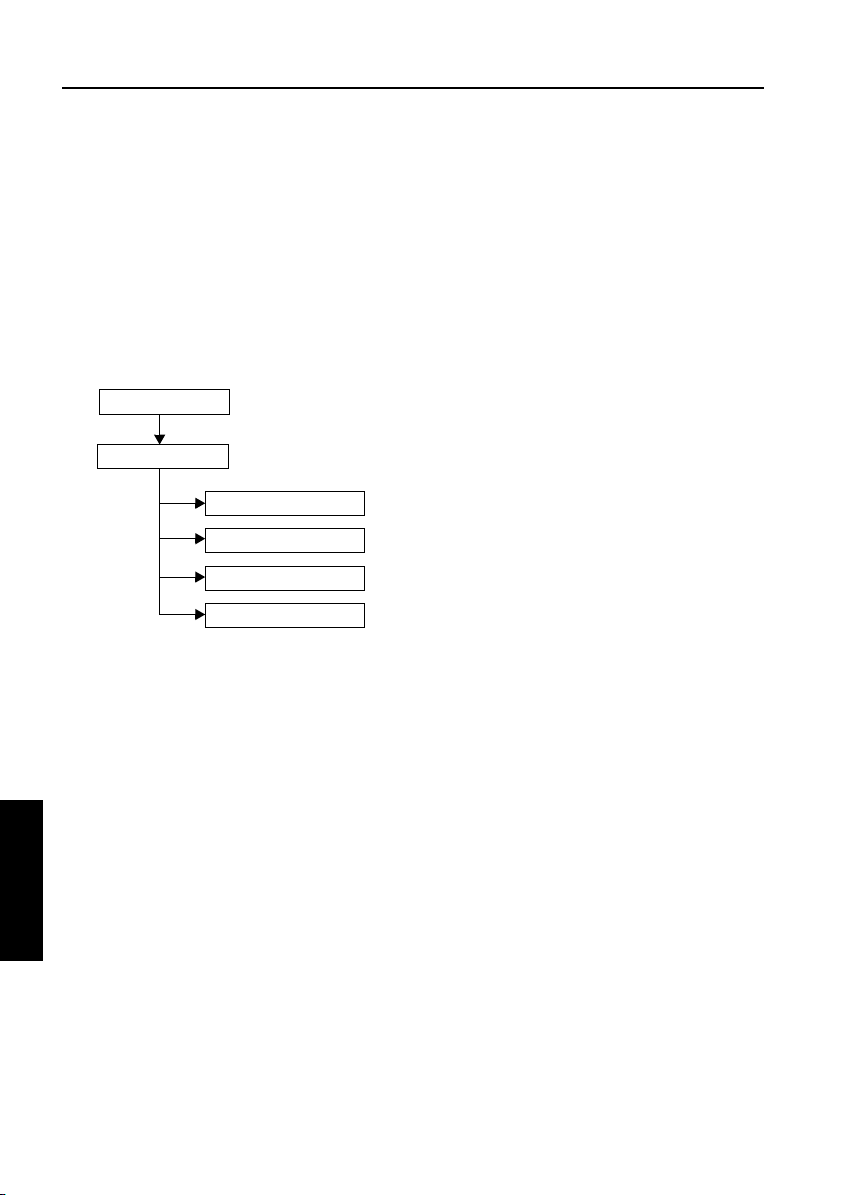
[2] Data flow
PC/ISW Tool
Image control
Operation board
Printer control
RADF control board
Video I/F board
Important Note:
The availability of the Graphics control board is
prerequisite to updating ROM data on other
boards.
(2) HELP + CHECK mode
Turning ON the copier with HELP and CHECK
puts it into the HELP + CHECK mode. If the
copier has the image control program installed,
but not the operation control program, the 25
mode would not launch. This mode is specifically
maintained to enable ISW in this situation.
2. 25 mode
The 25 mode works only where the copier
has both the image control and operation
control programs installed.
(Some part of HELP+CHECK mode is used
to update the operation control program in
25 mode.)
[3] Prepare the copier to start an ISW
transfer
1. Transfer modes
The copier supports three transfer modes as
ISW
5
3 DIS./ASSEMBLY
described below.
(1) Power-on mode
If the copier does not have the image control program installed, its writing to the copier is enabled
when the main switch is turned on. Because the
image control board controls the power supply to
the operation board, nothing will appear on the
operation LCD and timer LED will blink even
though the operation control program has been
installed on the copier.
5-2
Page 5

3. Instances of ISW transfer
(1) Writing ROM data newly (Ex. after replacing boards)
Normal startup display Writing method Condition
Image
control
Operation
control
Others Error code display 25 mode or
(2) Upgrading
Image
control
Operation
control
Others Normal
Flashing timer LED
No display on the operation LCD
Error code display Writing is enabled by launch-
Normal startup display Writing method Condition
Normal 25 mode or
Normal
Writing is enabled with power
turned ON.
ing the HELP + CHECK mode
HELP + CHECK mode
HELP + CHECK mode
ISW
The copier does not have the
image control program
installed.
The copier has the image control program installed.
The copier has the image control program installed.
The copier has all the programs
installed.
5-3
ISW
5
3 DIS./ASSEMBLY
Page 6
ISW
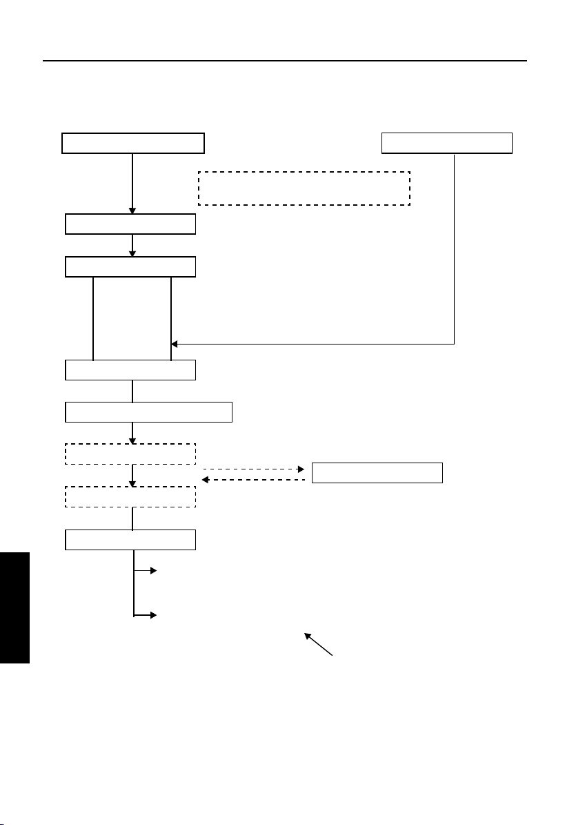
[4] HELP + CHECK mode operation flow
Power ON (HELP + CHECK)
PC
ISW : Choose a board.
ISW : Choose an item.
PC
Start ISW : Confirmation window
Start ISW
Finish ISW
Exit window
From the 25 mode menu
Some parts of this mode is used to update
the operation control program from 25 mode.
Choose “PC.”
Chose one from followings.
1. GRAPHIC CONTROL (Image control)
2. PRINTER CONTROL (Printer control)
3. OPERATION CONTROL (Operation control)
4. ADF (RADF control)
5. VIF (Video I/F)
Choose from among I1, C1 to C4 (batch or individual), O1 to O5
(batch or individual), F1, and V1.
Data
Main Body
Normal end : *** NORMAL END ***
ISW
5
3 DIS./ASSEMBLY
Abnormal end : *** ABNORMAL END ***
DATA ERROR
Changes by the error situation
5-4
Page 7

ISW
[5] HELP + CHECK mode operating pro-
cedure
1. Prerequisite
Turn the main SW ON while pressing “HELP” and
“CHECK” button.
2. ISW write mode select menu
Function: This window lets you select a mode in
which to update ISW.
ISW WRITE MODE SELECT MENU
1. PC
PLEASE PUSH TEN-KEY
a. Operating instructions
(1) Choose ISW WRITE MODE
Choose “PC” for both using personal computer
and ISW Tool.
(2) To exit writing
Press 9 (EXIT) to open the power-off window.
9. EXIT
3. ISW device select menu
Function: This window lets you select the control
board on which to update ROM data.
You can choose from among graphics
control, printer control, operation
control, ADF, and VIF.
ISW WRITE MODE SELECT MENU
1. GRAPHIC CONTROL
2. PRINTER CONTROL
3. OPERATION CONTROL
4. ADF
5. VIF
PLEASE PUSH TEN-KEY
a. Operating instructions
(1) Select the control board on which to update ROM
data. Choose from among 1 to 5. When you
select a number, the associated item select
menu appears.
(2) To return to the previous window
Press 0 (PREVIOUS) to return to the ISW write
mode select menu.
(3) To exit writing
Press 9 (EXIT) to open the power-off window.
[MODE:PC]
0. PREVIOUS 9. EXIT
5-5
ISW
5
3 DIS./ASSEMBLY
Page 8

ISW
4. Item select menu
Function: This window lets you select write
items.
OPERATION CONTROL - ITEM SELECT MENU
1. 01
2. 02
3. 03
4. 04
5. 05
6. ALL
PLEASE PUSH TEN-KEY
a. Operating instructions
(1) Individual write
Choose from among 1 to 5. When you select a
number, the start confirmation window opens.
(2) Batch write
To write all items in a batch, select “ALL.” When
you select “ALL,” the start confirmation window
opens.
(3) To return to the previous window
Press 0 (PREVIOUS) to return to the ISW device
select menu.
(4) To exit writing
Press 9 (EXIT) to open the power-off window.
0. PREVIOUS 9. EXIT
5. Start confirmation window
Function: This window prompts you to confirm
whether to start running ISW or not.
[MODE:PC] OPERATION CONTROL - 01
ISW START OK?
PLEASE PUSH TEN-KEY
a. Operating instructions
(1) Choose YES to start running ISW.
(2) Choose NO to cancel.
When you cancel, the item select menu appears
again.
6. Executing window
Function: This window displays the status of
execution in progress.
EXECUTING
[MODE:PC]
1. YES 2. NO
a. Operating instructions
(1) The executing indicator flashes. When the exe-
cution ends, the ending result window opens.
ISW
5
3 DIS./ASSEMBLY
5-6
Page 9

ISW
7. Ending result window
Function: This window displays the status of ISW
ending.
*** NORMAL END ***
PLEASE PUSH TEN-KEY
Abnormal end
*** ABNORMAL END ***
INPUT DEVICE ERROR
(ERROR CODE : xx)
PLEASE PUSH TEN-KEY
a. Operating instructions
(1) Choose 0 (CONTINUE) to return to the item
select menu.
(2) To exit writing
Press 9 (EXIT) to open the power-off window.
0. PREVIOUS 9. EXIT
0. PREVIOUS 9. EXIT
8. Power-off window
*** PLEASE TURN OFF A POWER SUPPLY ***
a. Operating instructions
(1) Individual write
Choose from among 1 to 5. When you select a
number, the start confirmation window opens.
5-7
ISW
5
3 DIS./ASSEMBLY
Page 10

ISW
[6] Error code table for ISW Setup
Error
Code
There is an error in the command to ISW processing unit.
01
A program error is detected.
1F
Input data format error. (during ISW to operation board)
41
Invalid machine name input data. (during ISW to operation board)
42
Invalid board name input data. (during ISW to operation board)
43
Input device error such as input time-out. (during ISW to operation board)
81
Failed to erase flash ROM. (during ISW to image control board)
C1
Write to flash ROM has failed. (during ISW to image control board)
C2
ROM checksum error. (during ISW to image control board)
C3
Output device error such as output time-out.
C4
Communication parameter error at image control unit to operation unit I/F.
E9
(during ISW to operation board)
Command sequence error at image control unit to operation unit I/F.
EA
(during ISW to operation board)
Communication time-out error at image control unit to operation unit I/F.
EB
(during ISW to operation board)
Flash ROM error (during ISW to operation board)
F0
Flash verify error (during ISW to operation board)
F1
Flash write error (during ISW to operation board)
F2
Flash erase error (during ISW to operation board)
F3
Receive checksum error at image control unit to operation unit I/F.
F8
(during ISW to operation board)
Receive header code error at image control unit to operation unit I/F.
F9
(during ISW to operation board)
Receive parity error at image control unit to operation unit I/F.
FA
(during ISW to operation board)
Receive framing error at image control unit to operation unit I/F.
FB
(during ISW to operation board)
Receive overflow error at image control unit to operation unit I/F.
FC
ISW
5
(during ISW to operation board)
Description
Action
No.
a
a
b
b
b
c
e
e
h
f
d
d
d
g
g
g
g
d
d
d
d
d
3 DIS./ASSEMBLY
5-8
Page 11

<Error code table action classification>
Action
No.
Program is not executing normally. Restart from power ON and re-execute the ISW.
a
Check the ISW transfer data file.
b
Check that the communication cable between input devices (PC or ISW tool) is properly connected.
c
Check the image control unit to operation unit I/F.
d
There is an error in the flash ROM on the image control board.
Restart from ISW. If the error persists, the life of the image control board flash ROM may have
e
expired. Replace the image control board.
An error was detected in the ISW target board. Check the ISW target board.
f
There is an error in the flash ROM on the operation board.
Restart from ISW. If the error persists, the life of the operation board flash ROM may have expired.
g
Replace the operation board.
* The system may fail to restart.
The checksum result after program write does not match the ROM checksum data of the ISW transfer data file.
h
Restart from ISW. If the error persists, the ISW transfer data file may not be created correctly.
[7] Preparing the copier to transfer
Start the copier with 25 mode enabled to put the
copier into ISW transfer wait state.
Step Procedure
Enter 25 mode.
1
[Memory setting mode menu Screen]
2
Press " ISW".
11
[ISW mode menu Screen]
Select the control board on which to
3
update ROM data.
[ISW mode Screen]
The key appears, indicating the
4
5
Start
copiers readiness to launch an ISW
transfer.
Follow operating instructions in Minolta
ISW (In-System Writer) Service Hand
book.
Action
ISW
ISW
5
3 DIS./ASSEMBLY
5-9
Page 12
ISW
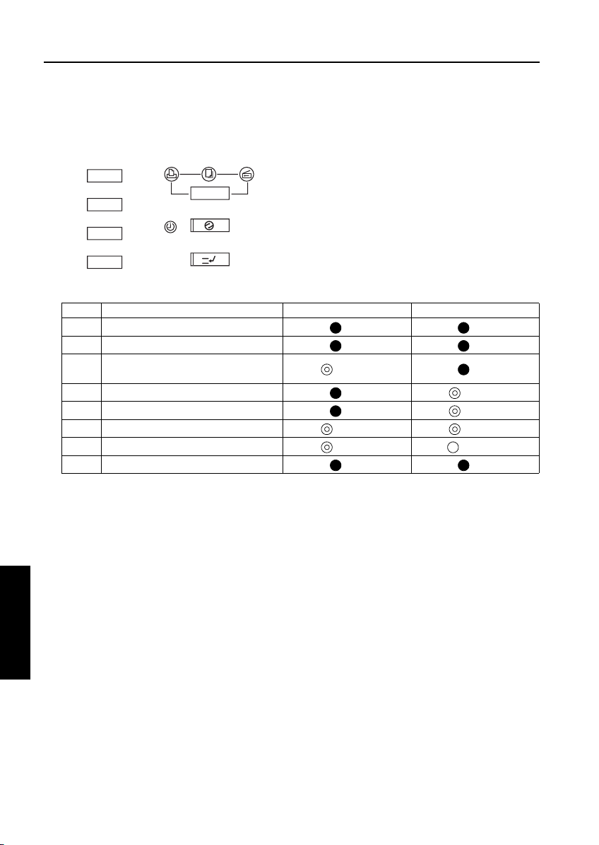
[8] Relationships between processing states and operational LEDs
Note: This is displayed only when installing the program to graphics control for the first time.
Print
Copy
Energy Saver
Timer
Interrupt
No. Processing Timer LED (orange) Energy Saver LED (green)
1 Initializing CPU now
2 Checking memory
3 Memory check error
(waiting for data from PC)
4 ISW processing (receiving data)
5 ISW processing (writing to flash ROM)
6 Transfer data error
7 Flash ROM write error
8 Memory check successful and reboot
[9] Rewriting procedure after an error
interruption
If errors occur while writing ROM data, it is written the same way as explained in “Writing ROM
data newly” in "[3]-3. Instances of ISW transfer".
• Image control program
The timer LED (orange) flashes. (Nothing will
ISW
5
3 DIS./ASSEMBLY
appear on the operation LCD because communication with the operating unit is disabled.)
Retry ISW after turning the main switch OFF,
then ON.
• Operation control program
Since the 25 mode is disabled, launch the HELP
+ CHECK mode to retry ISW.
• Other control programs
Relaunch the 25 mode to retry ISW. (It is
assumed that the copier has both the image control and operation control programs successfully
installed.)
Scan
OFF OFF
OFF OFF
Flashing OFF
OFF Flashing
OFF Flashing
Flashing Flashing
Flashing Steady lit
OFF OFF
5-10
Page 13
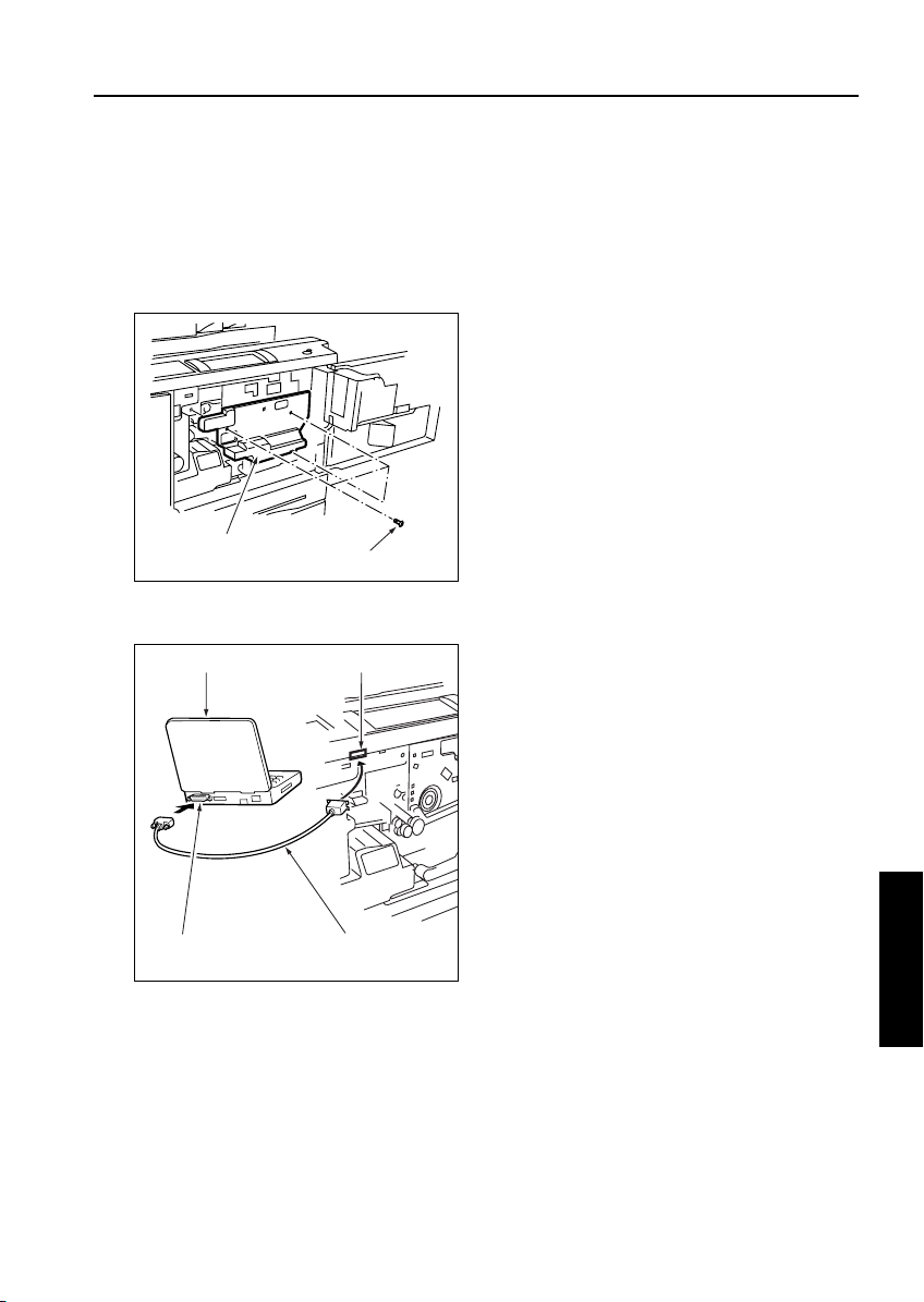
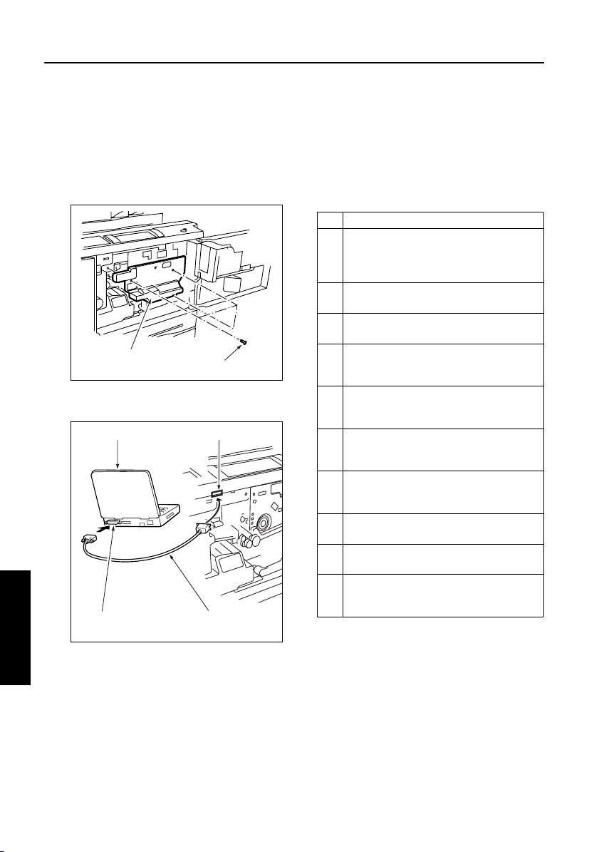
[10] Connecting the ISW connector
The ISW connector is hidden under the drum
cover. Detach this cover to run ISW.
a. Procedure
(1) Open the left and right front doors.
(2) Open the toner supply unit.
(3) Loosen three screws to detach the drum cover.
ISW
Drum cover
Screws (3)
(4) Connect the PC parallel port and the copier ISW
connector with parallel interface cable.
PC
interface port
ISW connector (36-pin)
Centronics cableParallel (printer)
ISW
5
3 DIS./ASSEMBLY
5-11
Page 14
ISW
UPDATING WITH ISW Trns
[1] Setting Up ISW Trns
Note: The explanation screen here is used based on
another model. Therefore, there is a thing different from an actual screen.
1. Installing the application program
Install the ISW Trns on the PC.
Step Procedure
Boot the PC.
1
2 Mount setup disk 1 on the PC and double-
click the [Setup.exe] icon to start the installer.
Note: If an old version ISW Trns program is
present, uninstall it first, then start
the setup operation.
3 [ISW Trns setup window]
Confirm the installation folder as instructed by
on-screen guidance and click Next.
Note1: By default, the program installs in
[C:\Program_File\Minolta\ISWTrns
for Minolta].
Note2: To change the installation folder,
click Browse and type a new folder
name.
4 [Program folder confirmation window]
Confirm the ISW Trns program installation
folder as instructed by on-screen guidance
and click Next.
Note1: By default, the ISW Trns program
installs in [ISWTrns for Minolta].
Note2: To change the installation folder,
either type a new folder name or
select one from the list of existing
folders on display.
5 [Next disk insertion request window]
Mount setup disk 2 as instructed by onscreen guidance and click OK.
ISW
5
3 DIS./ASSEMBLY
6 [Information dialog box]
Click OK as instructed by on-screen guidance.
Note: This procedure will add an ISW Trns
icon to the Start menu.
7 [Setup completion window]
Click Complete as instructed by on-screen
guidance.
8 The ISW Trns install exits automatically.
2. Setting up ISW Trns
When the ISW Trns program has been installed
on the PC, run it to set up a folder in which the
transfer file (update data) is stored. When this
setting completes, the ISW Trns program is
ready to run.
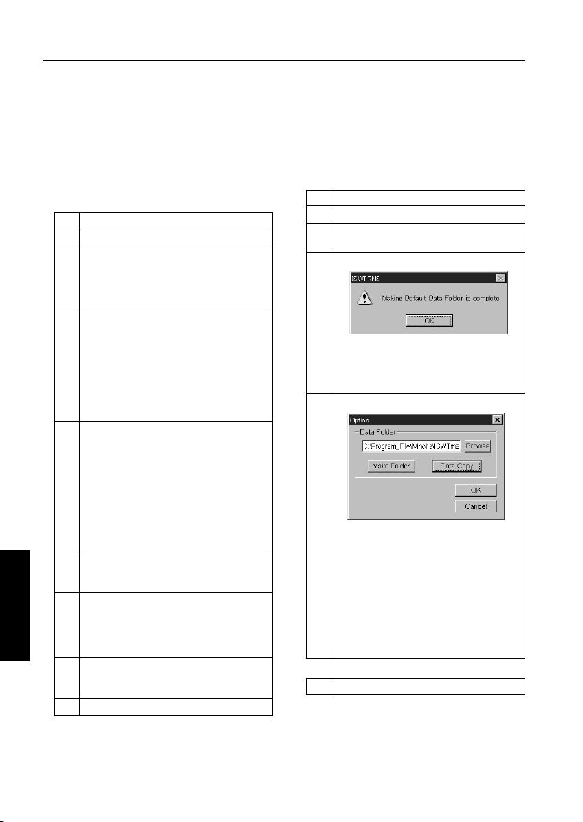
Step Procedure
1 Boot the PC.
2 [Select [ISW Trns] from the start menu to run
the ISW Trns program.
3 [ISW Trns dialog box]
Click OK to set up a folder in which the transfer file (update data) is stored.
Note: This dialog box will not appear when
ISW Trns is run next time.
4 [Option window]
Set up a folder in which the transfer file
(update data) is stored and click Make Folder.
Note1: By default, the folder in which the
ISW Trns program has installed
(C:\Program_File\Minolta\ISWTrns
for Minolta) has been set up as a
storage folder (data folder).
Note2: To change the storage folder, click
Browse and select a new folder or
type its full-path name in directly the
edit box.
Step Procedure
5-12
Page 15
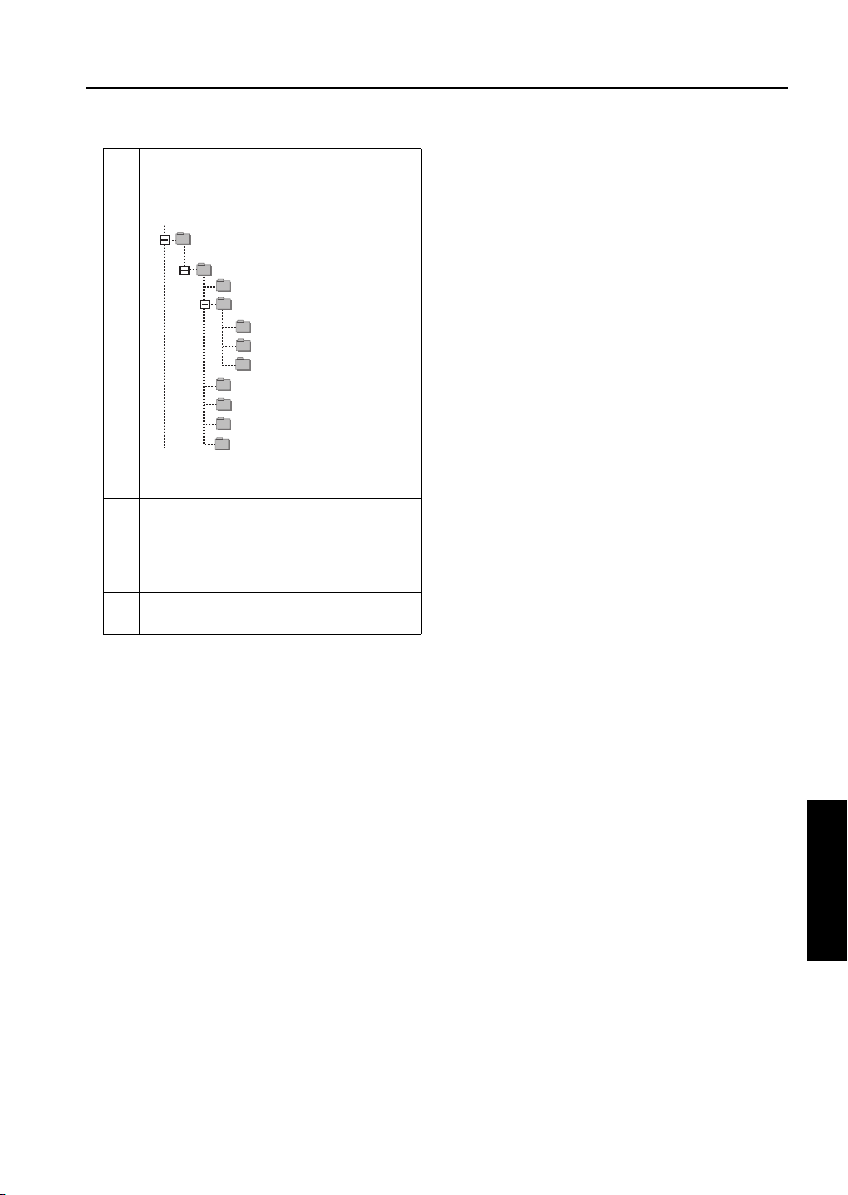
Note3: Clicking Make Folder will create the
following hierarchy of folders
branching off from the new storage
folder:
ISWTrns for Minolta
Di850
Edh
Image
Euro
Japan
Usa
Printer
Vif
Operation
Fns
Note: Pctrl and Vit Indications can not be
function.
5 [Option window]
Click OK.
Note: This procedure will save the data
folders created in Step 4 to the INI
file for the ISW Trns program.
6 [ISW Trns main window]
The ISW Trns main window opens.
ISW
5-13
ISW
5
3 DIS./ASSEMBLY
Page 16
ISW
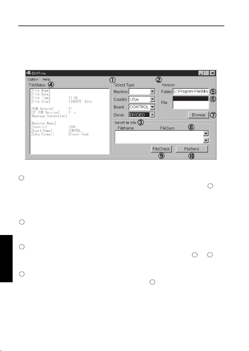
3. ISW Trns Main Window Overview
The ISW Trns program, when run, comes up with the ISW Trns main window. The ISW Trns main window
lets you select, verify, and transfer a transfer file (update data) and display information in it. A detailed
description of its functions follows:
85img_dc0001
2002/ 6/15
Di850
Di850
85img_dc0001.b01
85img_dc0001.b00
85img_dc000.b01
* Sample display : Display information may be different from what you actually will see on your machine.
A Select Type frame
1
Select conditions for a transfer file (update data). When you select all the four combo boxes, folder is set
up on the basis of the information set in the INI file.
The settings of the combo boxes selected are saved to the ISW Trns.INI file when you click File Send. The
ISW Trns program comes up with the ISW Trns main window prefilled with these combo box settings when
runs next time.
Version selection frame
2
This frame lets you select which version of a transfer file you want transmitted when more than one version
is stored in a single folder.
Send file information frame
3
List the files that are transferred actually on the basis of the information specified in frames and . Click
ISW
5
File Check to view a checksum of each file and its consistency (OK, NG or ??).
5
1 2
3 DIS./ASSEMBLY
File Status frame
4
View detailed information about the version file as it is selected in .
6
The table below presents differences in the ways transfer files are displayed according to their data distribution
types.
5-14
Page 17

Data sources appearing in the detailed file information list
Display title ORIGINAL (Batch data) DIVIDE (Divided data)
File Name File name of the version selection file File name of the version selection file
File Date Date of the version selection file Date of the version selection file
File Time Time of the version selection file Time of the version selection file
File size File size of the version selection file File size of the version selection file
ROM Version Footer information Footer information (last file)
SP ROM Version Footer information Footer information (last file)
Message Conversion For development use For development use
Machine Name Header information + INI file Header information + INI file
Country Combo box display Combo box display
Board Name Header information + INI file Header information + INI file
Data Format Header information (Binary) Header information (Binary)
Version Folder edit box
5
When Select Type frame is established, the
full-path folder name is displayed to reflect the
data folder and the INI file information set up in
the option window. If the transfer file exists in a
folder different from the data folder, change the
folder name to that folder by using Browse or
rewriting the folder name directly.
Those transfer files in the folder that meet the INI
file conditions are listed in File list box .
Version File selection list box
6
Lists those display files existing in the folder set
in .
5
Display Files are marked by a wildcard name
(such as 85img*.b01) in the ISWTrns.INI file. If
multiple versions of a file exist in the folder, there-
fore, multiple versions would appear in this list
box accordingly.
Example: 85img_dc0001AAA.bol
85img_dc002AAA.bol
1
7
6
Browse Version File button
7
Click Browse button to open the folder selection
window and select a folder for .
Send file information display list
8
List the names of files that are actually transmit-
ted when a version file is selected in . A count
of the number of files that are actually transmitted is indicated in a checksum file attached to
each transfer file (write data). If not all the trans-
fer files are stored in folder or if extra files are
included in it, the error message “Send files not
found or invalid file name in the folder” is displayed. This check is not made.
Clicking the File Check button in calculates
a checksum of the display files as a whole and
compares it with the checksum stored in the
checksum file (*.SUM) attached to the transfer
file (write data), displaying the result of that comparison.
5
ISW
5
6
9
ISW
5
3 DIS./ASSEMBLY
The files in this list are sorted by name. When the
list opens, the last display item in the list is pre-
selected. Change the choice to establish the ver-
sion of transfer files to transmit.
5-15
Page 18

ISW
File Check button
9
Click this button when send files are listed in the
Send File Info list in , and a file checksum of
8
the transfer files displayed (file checksum) is calculated and attached to each file. Further, the
calculated checksum is compared with the
checksum storage file (*.SUM) attached to the
transfer file (write data) to display the result of the
comparison in the following format:
[OK] = Matched
[NG] = Unmatched
[??] = Checksum file (*.SUM) not found
File Send Button
10
Perform transmission of transfer files
4. Parallel port setup
If a parallel data transfer is to be executed with
the ISW Trns program, the ECP mode setting of
the PC parallel port should be cleared. ISW Trns
does not support parallel data transfers. If a parallel data transfer is launched with the PC set in
ECP mode, the transfer could be aborted by an
error occurring in between. It would be necessary, therefore, to disable ECP mode before run
ISW Trns on a PC with the ECP setting.
Instructions on how to disable ECP mode are
given below.
Step Procedure
1 Boot the PC.
2 Open the System icon in the Control Panel
and click the Device Manager tab. Then,
search for LPT1 in Ports (COM/LPT1).
Note1: If LPT1 appears as ”ECP Printer
Port (LPT1),” then it is an ECP port.
Note2: If LPT1 appears as “Printer Port
(LPT1),” then it is a regular parallel
port.
3 With an ECP printer port, change the BIOS
setting of the PC to disable the ECP port.
Note: Because the BIOS setting depends
on the PC, check with your system
administrator on how to disable ECP
mode.
4 When the BIOS change is complete, open the
System icon in the Control panel and change
the parallel port driver.
5 Run a send test to verify the successful oper-
ation.
Note: If a transfer succeeds on one copier
model, then transfers would be successful on all models.
ISW
5
3 DIS./ASSEMBLY
5-16
Page 19
ISW
[2] Copying Transfer Data (Update Data)
Run the ISW Trns program to copy transfer data
(update data) to the PC.
Step Procedure
1 Boot the PC.
2 Select ISW Trns from the Start menu to run
the ISW Tr ns program.
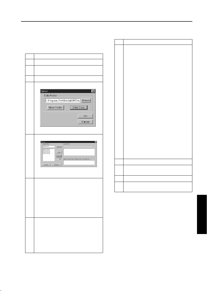
3 Click the Option menu.
4 [Option window]
Click Data Copy.
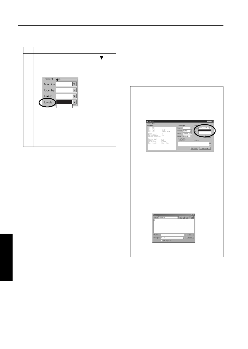
5 [File Copy window]
C:\Program files\Minolta\ISW\Trns\
Mount an update disk on the PC and click
Browse.
6 Select the folder on drive A that contains the
transfer file (update data) as a source file.
Note1: The selected folder is displayed in
the upper section in the Original
Files field.
Note2: The transfer files (update data) that
are stored in the selected folder are
displayed in the lower section in the
Original Files field.
7 Select the transfer files (update data) you
want copied from the lower section in the
Original Files field.
Note1: You can select multiple transfer files
(update data).
Note2: To copy all the files (update data)
displayed, skip this step to go to
Step 8 directly.
Step Procedure
8 Click Copy to copy the selected transfer files
(update data) to the folder created at ISW
Tr n s se t u p.
Note1: To copy all the files (update data)
displayed in the Original Files field,
click Copy All, instead of Copy.
Note2: The folder name created at ISW
Trns setup is displayed above the
Copied File field.
Note3: The transfer files that have been
copied successfully so far are listed
in full-path name in the lower part of
the Copied File list view.
The transfer files that have not been
copied successfully are listed in the
Failed to Copy Files list view.
Causes of copy errors:
1. A file with the same name existed
and the O/W (overwrite) check
box was not checked.
2. The storage destination folder
could not be found.
3. Attempted to overwrite an overwrite protected file.
Note4: To update existing transfer files
(update data), check the O/W (overwrite) check box.
9 When the copying completes, click Refresh.
10 If more update disks are involved, repeat
Steps 5 to 9.
11 Click Cancel to return to the option window.
12 [Option window]
Click OK.
ISW
5
3 DIS./ASSEMBLY
5-17
Page 20
ISW
[3] Connecting the Di850
The ISW connector is hidden under the drum
cover. Detach this cover to run ISW.
a. Procedure
(1) Open the left and right front doors.
(2) Open the toner supply unit.
(3) Loosen three screws to detach the drum cover.
Drum cover
(4) Connect the PC parallel port and the copier ISW
connector with parallel interface cable.
PC
ISW
5
interface port
Screws (3)
ISW connector (36-pin)
Centronics cableParallel (printer)
[4] Updating
1. Update operation overview
Follow the steps below to update the ROM data
on each control board using ISW Trns. For more
operational details, see the relevant parts of this
section.
Step Procedure
1 Check the ROM version of the copier before
proceeding with updating. (See 2. “Checking
the ROM version of the copier (before updating).”)
2 Run the ISW Trns program. (See 4.”Running
ISW Trns.”).
3 Set the copier in ISW receive mode.
(See 3. “Preparing the copier to transfer.”)
4 Select conditions for transfer files (update
data) with IWS Trns. (See 5. “Selecting transfer file (update data) conditions.”)
5 Select a version of transfer files (update data)
with IWS Trns. (See 6.“Selecting a version of
transfer files (update data).”)
6 Verify the transfer files (update data) selected
with IWS Trns. (See 7.“Verifying transfer files
(update data).”
7 Transmit the transfer files (update data) with
IWS Trns. (See 8.“Transmitting transfer files
(update data).”)
8 To update ROM data on more control boards,
repeat Steps 3 to 7.
9 Exit the ISW Trns program. (See 9.“Exiting
ISW Trns.”)
10 Verify the ROM version of the copier after
updating. (See 10.“Verifying the ROM version
of the copier (after updating).”)
3 DIS./ASSEMBLY
5-18
Page 21
ISW
2. Checking the ROM version of the copier
(before updating)
Before updating ROM data, check the ROM version of the existing control program in the 25
mode.
Step Procedure
1 Turn OFF the copier main switch.
2 Turn ON the copier main switch while holding
down the copy count setup buttons 2 and 5, to
enable 25 mode.
3 [25 mode menu window]
Check the ROM version by following the
copier-specific procedure.
Note: For operating instructions, refer to
the Adjustment section of the service
manual supplied for the copier.
3. Preparing the copier to transfer.
Start the copier with 25 mode enabled to put the
copier into ISW transfer wait state.
Step Procedure
1 Turn OFF the copier main switch.
2 Turn ON the copier main switch while holding
down the copy count setup buttons 2 and 5, to
enable 25 mode.
3 [25 mode menu window]
Put the copier into ISW transfer wait state by
following the copier-specific procedure.
Note1: “ISW transfer wait state” is the state
of the copier with the “START” key
being shown in the display area.
Note2: For operating instructions, refer to
the Adjustment section of the service manual supplied for the copier.
4. Running ISW Trns.
Run the ISW Trns program.
Step Procedure
1 Boot the PC.
2 Select ISW Trns from the Start menu and run
the ISW Tr ns program.
5. Selecting transfer file (update data) conditions
Select various conditions for selecting the transfer files (update data) in the ISW Trns main window. Conditions to select are:
• (Machine) The name of the model on which
ROM data is updated.
• (Country) The destination of the transfer files
(update data)
• (Board) The name of the board on which ROM
data is updated
• (Divide) The type of the transfer files (update
data)
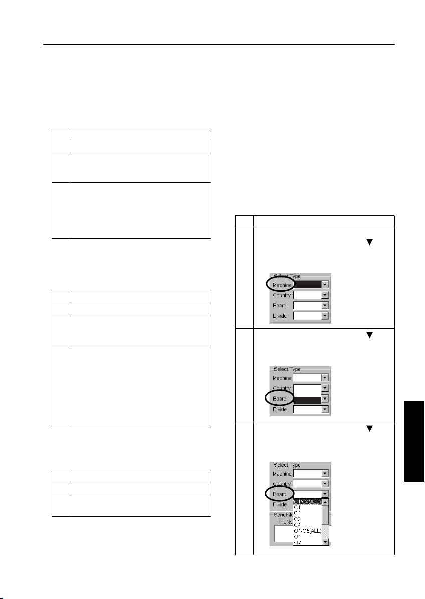
Step Procedure
1 [ISW Trns main window]
In the ISW Trns main window, click in the
[Machine] field in [Select Type] and select the
name of the model on which to update ROM
data from the pull-down menu.
Di850
2
In the ISW Trns main window, click in the
[Country] field in [Select Type] and select the
destination of the transfer files (update data)
from the pull-down menu.
Di850
Euro
Japan
USA
3
In the ISW Trns main window, click in the
[Board] field in [Select Type] and select the
name of the board on which to update ROM
from the pull-down menu.
Di850
USA
ISW
5
3 DIS./ASSEMBLY
5-19
Page 22
ISW
Step Procedure
4
In the ISW Trns main window, click in the
[Divide] field in [Select Type] and select a
method of dividing the transfer files (update
data) from the pull-down menu.
Di850
USA
C1/C4(ALL)
ORIGINAL
DIVIDED
Note1: Normally, select ORIGINAL as the
method of division.
Note2: Select DIVIDED for large ROM data
(e.g. for Main Control Unit), that is
divided into several files (extension.001.b01, etc.) to be stored to
several floppy disks for distribution.
6. Selecting a version of transfer files
(update data)
When a transfer file (update data) has been chosen to meet a given set of conditions, it may be
available in multiple versions. Here, select a particular version of a transfer file (update data) for
use in the actual data transfer.
Step Procedure
1 [ISW Trns main window]
In the ISW Trns main window, select a transfer file (update data) of the version that is used
in the actual data transfer from among the
files listed in the [File] field in [Version].
85img_dc0001
2002/ 6/15
Di850
Note: The version of a transfer file (update
data) can be determined from its file
name.
Example:
85img_DC001AAA.b01 .. Version 1
85img_DC002AAA.b01 .. Version 2
2 The target file (update data) may not be
shown in the [File] field in [Version], if it exists
in a folder different from the data folders set in
the Option screen. Click Browse and find the
appropriate file to select.
Di850
85img_dc0001.b01
85img_dc0001.b00
85img_dc000.b01
Di850
Di850
Note: Clicking Browse will open the Select
File window.
ISW
5
3 DIS./ASSEMBLY
5-20
Page 23
ISW
7. Verifying transfer files (update data)
Once a particular version of a transfer file
(update data) is selected, the transfer files
(update data) that are transmitted actually are
listed in [Send File Infor] in the ISW Trns main
window. Verify the validity of the transfer files
(data) for transfer.
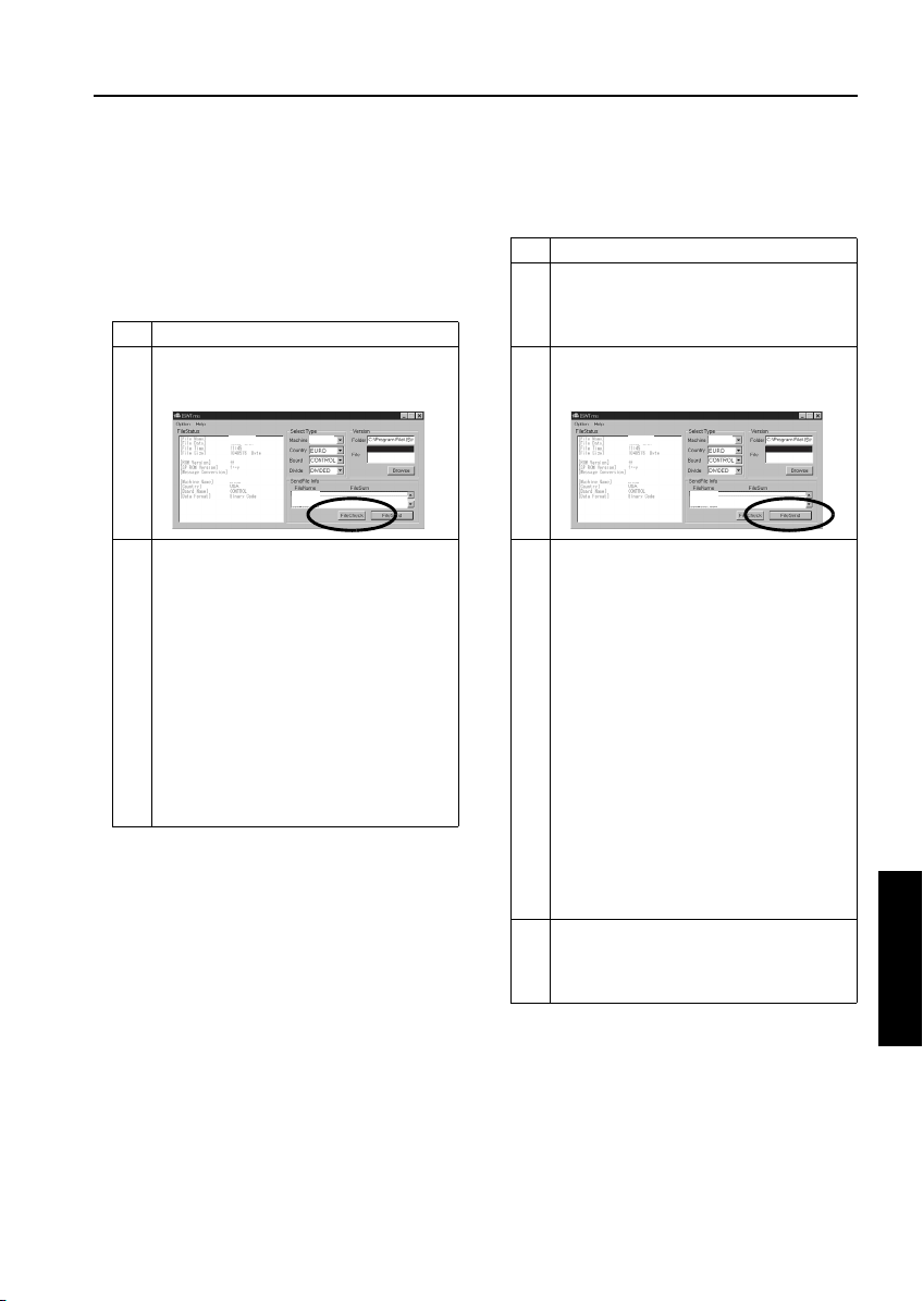
Step Procedure
1 [ISW Trns main window]
In the ISW Trns main window, click File Check
in [Send File Infor].
85img_dc0001
2002/ 6/15
Di850
2 Check to see if OK appears in the [File Sum]
field in [Send File Infor] in the ISW Trns main
window.
Note1: A file that is labeled NG is inappro-
priate as a transfer file (update
data). Try to copy the file again. If
you can not succeed to copy it
again, the original file may be corrupted.
Note2: Transfer files (update data) may be
marked ?? when enough information is not available to verify their
validity. When a transfer file is
labeled, check if the checksum file
(*.sum) was copied correctly.
Di850
85img_dc0001.b01
85img_dc0001.b00
85img_dc000.b01
8. Transmitting transfer files (update data)
When transfer files (update data) are established, run a data transfer to the copier.
Step Procedure
1 Press the “START” key on the copier while it
is in ISW transfer wait state.
Note: The “START” key is displayed in the
display area on the copier.
2 [ISW Trns main window]
Click File Send in [Send File Infor] in the ISW
Trns main window.
85img_dc0001
2002/ 6/15
Di850
3 Transfer files (update data) are transmitted to
the copier.
Note1: While data is being transferred to a
copier, an LED or indicator flashes
to indicate a data transfer in
progress. The mode of such indication varies from one copier to
another.
Note2: ISW Trns produces an indication to
designate a data transfer in
progress.
Note3: If a data transfer is aborted due to
any trouble occurring with the copier
or ISW Trns, turn the copier main
switch OFF, then ON to retry the
data transfer by ISW Trns. In this
case, a condition indication and
necessary operation vary depending on each model. Please refer to
service manual for the copier.
4 To update ROM data on more control boards,
repeat the step in 5, “Selecting transfer file
(update data) conditions,” to 8, “Transmitting
transfer files (update data).”
Di850
85img_dc0001.b01
85img_dc0001.b00
85img_dc000.b01
ISW
5
3 DIS./ASSEMBLY
5-21
Page 24

ISW
9. Exiting ISW Trns.
When the update of the ROM data on the control
boards completes, exit the ISW Trns program.
Step Procedure
1 Exit the ISW Trns program.
2 Turn OFF the PC.
3 Turn OFF the copier main switch.
4 Disconnect the parallel interface cable from
the PC and the copier.
Note: Turn OFF the PC and copier before
disconnecting the parallel interface
cable from them.
10. Verifying the ROM version of the copier
(after updating)
When the update of the ROM data completes,
verify the ROM version of the control program in
the 25 mode.
Step Procedure
1 Turn OFF the copier main switch.
2 Turn ON the copier main switch while holding
down the copy count setup buttons 2 and 5, to
enable 25 mode.
3 [25 mode menu window]
Check the ROM version by following the
copier-specific procedure.
Note: For operating instructions, refer to
the Adjustment section of the service
manual supplied for the copier.
ISW
5
3 DIS./ASSEMBLY
5-22
Page 25

[5] ISW Trns Messages
The ISW Trns program displays dialog messages when errors occur and when processing ends. Definitions
of these messages are listed below, along with the associated display status.
Message Display status
Cannot open a checksum file Opening of a checksum file failed. Possible causes include
Cannot read a checksum file Loading of a checksum file into memory failed. Possible
Cannot open a file Opening of a send file failed. Possible causes include a cor-
File transmission complete File transfer completed.
Cannot open the LPT port Opening of the LPT port failed.
Communications port setup acquisition error A call to GetCommSate failed.
Communications port setup error A call to GetCommSate failed.
Cannot open a send file Opening of a send file failed. Possible causes include a cor-
Cannot send a Term Test file Transmission of a communications test block failed.
Unsuccessful file transmission The transmission of a send file failed. Possible causes
Unsuccessful transmission to the LPT port Output to the LPT port failed. Possible causes include a
Starting file transmission. OK? A message seeking confirmation at the start of file trans-
Send file not selected No files exist on the send file list.
Canceled Transmission of a file in progress was canceled. CANCEL
Default data folder created A data folder was created by clicking Create Folder.
Invalid folder name An invalid folder name was entered. Start a folder name
Default data folder not set.
Set a folder.
Unsuccessful thread creation The creation of a thread failed.
Copying the selected file. OK? File copy start message
Copying all files to the default data folder. OK? File copy start message
No send file available No file to copy file is selected or exists in the folder.
Unable to copy several files 1. The destination folder does not exist.
a corrupted file and a file in use.
causes include a shortage of memory and an OS problem.
rupted file and a file in use.
rupted file and a file in use.
1. The copier is not ready to receive.
2. The cable is out of position.
3. Transmission of the wrong send file was attempted.
include a cable out of position.
cable out of position.
mission.
is normally hidden. Its setting can be altered with the INI
file.
with a drive name, such as C:\.
A data folder is not set in ISWTrns.INI. This message is displayed when ISW Trns launches for the fist time.
2. When the Overwrite check box is not checked, an
attempt is made to copy to a file having the same file
name.
3. An attempt is made to overwrite a protected file
4. Any other cause (such as a file being used by another
application or OS problem)
ISW
ISW
5
3 DIS./ASSEMBLY
5-23
Page 26

ISW
Message Display status
File copying end File copying completed.
Send file not found, or invalid file name in the
folder. Check.
The number of divisions of a send file recorded in the
folder. Check. checksum file and the number of files actually existing do not
match.
1. A file having an invalid file name exists in the data folder.
Delete possibly invalid file names from the folder list.
2. The number of files in a divided file is wanting. Identify the
wanting files in the folder list and recopy them.
ISW
5
3 DIS./ASSEMBLY
5-24
Page 27

ISW
[6] Troubleshooting ISW Trns
If errors occur while running the ISW Trns program,
take the actions suggested below to correct them.
1. Unable to run ISW Trns
• Corrupted ISWTrns.EXE file
→ Set up again.
• The setup disk is corrupted.
→ Verify the setup disk and then set up again.
2. Send file is not displayed when a combo
box item is selected
• The send file is not stored in the folder.
→ Check to see if the send file is stored in the
folder appearing in the [Folder] text box in
[Versions]. Use the [File Copy] function if the
file storage location is unknown.
• Check to see if the base data folder setting
in the option window is not wrong.
→ Verify the base folder setting. Use the [File
Copy] function if the file storage location is
unknown.
• Invalid file name (altered)
→ The file name of a file must be used exactly
as it is delivered. If a file is renamed, it cannot be displayed or selected. If a file name
has been altered, return it to its original file
name.
• Invalid folder name (altered)
→If a folder as created with [Make Folder] in
the option window is renamed, it cannot be
located. Restore the original folder name
and check.
5. Unsuccessful file transfer
a. “Cannot open a file” error
• The file is used by any other program or by
the system.
→ Close that other program. If the file transfer.
still fails, reboot Windows.
b. “Cannot send a Term Test file” error
• The cable is not in firm position.
→ Check to see if the cable is inserted in firm
position or if the cable is not impaired.
• The copier is not ready to receive.
→ Check to see if the copier is ready to receive.
c. “Unsuccessful transmission to the LPT port”
error
• The cable is not in firm position.
→ Check to see if the cable is inserted in firm.
position or if the cable is not impaired.
• Invalid data has been transmitted.
→ Check from the file information window to
see if the receive mode (receiving board
type) of the copier and the send file on the
PC match.
→ If the file is transmitted for the first time,
check with its vendor.
• The PC parallel port is set in ECP mode.
→ Consulting the manual, free the parallel
port from ECP mode.
• Compatibility between the PC parallel port
and the copier port.
→ Verify by testing on a PC with proven trans mission performance.
• Use a cable shorter than 2 meters in length.
3. NG produced by a file check
• Corrupted send file
→ Copy the file again and recheck. If NG
re-curs, check with the vendor of that file.
4. “??” produced by a file check
• With any other model, the checksum file
(*.SUM) had not been copied when the send
file was copied to the PC.
→ Copy the checksum to the same folder as
the file is copied. It would be copied auto
magically if the [File Copy] function is used.
5-25
ISW
5
3 DIS./ASSEMBLY
Page 28
ISW
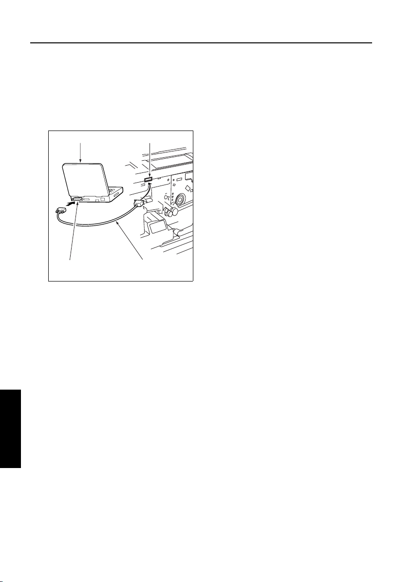
[7] Connecting to the ISW connector
The ISW connector is at the right side of the
copier.
a. Procedure
(1) Connect the PC parallel port and the copier ISW
connector with a
PC
Centronics cable.
ISW connector (36-pin)
interface port
ISW
5
Centronics cableParallel (printer)
3 DIS./ASSEMBLY
5-26
Page 29

2002 MINOLTA CO., LTD.
Copyright
Use of this manual should be strictly supervised to
avoid disclosure of confidential information.
MINOLTA Co.,Ltd.
7662-4027-11 02080000
 Loading...