

Page 1

INSTRUCTION MANUAL
IP-431
Read this manual before printing.
Keep readily available for reference.
Page 2

Thank you very much for purchasing the IP-431.
This INSTRUCTION MANUAL includes instructions for making prints, correct handling of the
machine, and precautions for safety. Please read this manual before printing.
In order to maintain a satisfactory printing performance, please keep this INSTRUCTION
MANUAL readily available for reference.
Page 3

Contents
SOFTWARE LICENSE AGREEMENT
This package contains the following materials provided by Konica Corporation (Konica): software included as part of
the printing system, the digitally-encoded machine-readable outline data encoded in the special format and in the
encrypted form (“Font Programs”), other software which runs on a computer system for use in conjunction with the
Printing Software (“Host Software”), and related explanatory written materials (“Documentation”).
The term “Software” shall be used to describe Printing Software, Font Programs and/or Host Software and also
include any upgrades, modified versions, additions, and copies of the Software.
The Software is being licensed to you under the terms of this Agreement.
Konica grants to you a non-exclusive sublicense to use the Software and Documentation, provided that you agree
to the following:
1. You may use the Printing Software and accompanying Font Programs for imaging to the licensed output
device(s), solely for your own internal business purposes.
2. In addition to the license for Font Programs set forth in Section 1 (“Printing Software”) above, you may use
Roman Font Programs to reproduce weights, styles, and versions of letters, numerals, characters and
symbols (“Typefaces”) on the display or monitor for your own internal business purposes.
3. You may make one backup copy of the Host Software, provided your backup copy is not installed or used on
any computer. Notwithstanding the above restrictions, you may install the on any number of computers
solely for use with one or more printing systems running the Printing Software.
4. You may assign its rights under this Agreement to an assignee of all of Licensee’s right and interest to such
Software and Documentation (“Assignee”) provided you transfers to Assignee all copies of such Software
and Documentation Assignee agrees to be bound by all of the terms and conditions of this Agreement.
5. You agree not to modify, adapt or translate the Software and Documentation.
6. You agree that it will not attempt to alter, disassemble, decrypt, reverse engineer or decompile the Software.
7. Title to and ownership of the Software and Documentation and any reproductions thereof shall remain with
Konica.
8. Trademarks shall be used in accordance with accepted trademark practice, including identification of the
trademark owner’s name. Trademarks can only be used to identify printed output produced by the Software.
Such use of any trademark does not give you any rights of ownership in that trademark.
9. You may not rent, lease, sublicense, lend or transfer versions or copies of the Software Licensee does not
use, or Software contained on any unused media, except as part of the permanent transfer of all Software
and Documentation as described above
10. In no event will Konica be liable to you for any consequential, incidental or special damages, including any
lost profits or lost saving, even if Konica has been advised of the possibility of such damages, or for any claim
by any third party. Some states or jurisdictions do not allow the exclusion or limitation of incidental, consequential or special damages, so the above limitations may not apply to you.
11. Notice to Government End Users: The Software is a “commercial item,” as that term is defined at 48 C.F.R.
2.101, consisting of “commercial computer software” and “commercial computer software documentation,” as
such terms are used in 48 C.F.R. 12.212. Consistent with 48 C.F.R. 12.212 and 48 C.F.R. 227.7202-1 through
227.7202-4, all U.S. Government End Users acquire the Software with only those rights set forth herein.
Macintosh® is a registered trademark of Apple Computer, Inc.
Windows® is a registered trademark of Microsoft Corporation.
Print Controller INSTRUCTION MANUAL i
Page 4

Contents
Contents
■ Introduction ................................................................................................. v
■ About Supplied Items ................................................................................. iv
■ About This Manual .................................................................................... vii
■ System Requirements .............................................................................. viii
● Windows ................................................................................................................. viii
■ Conventions Used in this Manual ...............................................................ix
Chapter 1 Overview ...........................................................................................1-1
■ Contents of this Chapter .......................................................................... 1-2
■ Overview of the Print Controller ............................................................... 1-3
● Print Controller and Printer Engine ........................................................................ 1-3
● Print Controller Hardware Configuration ................................................................ 1-4
● I/O Interface ........................................................................................................... 1-4
● Data Flow............................................................................................................... 1-5
● How to Use Memory .............................................................................................. 1-6
● General View ......................................................................................................... 1-7
■ About the Printer Driver ........................................................................... 1-8
● Compliant OS ........................................................................................................ 1-8
Chapter 2 Setup ................................................................................................2-1
■ Contents of this Chapter .......................................................................... 2-2
■ Installation of the Printer Driver ............................................................... 2-3
● Before Installation .................................................................................................. 2-3
● Installing to Windows95/98/Me .............................................................................. 2-3
● Installing to WindowsNT4.0/2000 .......................................................................... 2-4
● Uninstalling the Printer Driver ................................................................................ 2-6
■ Test Page ................................................................................................. 2-6
■ Print from Applications ............................................................................. 2-7
● Execution of Printing .............................................................................................. 2-7
● Print Settings ......................................................................................................... 2-7
■ Contents of Settings ................................................................................ 2-8
● Windows 95/98/Me ................................................................................................ 2-8
● Windows NT4.0.................................................................................................... 2-10
● Windows 2000 ..................................................................................................... 2-12
Chapter 3 Printer Driver ..................................................................................3-1
■ Contents of this Chapter .......................................................................... 3-2
■ Working Environment............................................................................... 3-3
● Compliant OS ........................................................................................................ 3-3
■ Property of Printer Driver ......................................................................... 3-3
■ Printer Driver Function List ...................................................................... 3-7
ii Print Controller INSTRUCTION MANUAL
Page 5

Contents
■ Description of Printer Driver Functions .................................................. 3-10
Chapter 4 Control Panel Setup........................................................................4-1
■ Contents of this Chapter .......................................................................... 4-2
■ About the Control Panel........................................................................... 4-3
● The Copier Control Panel ...................................................................................... 4-3
● How to Enter Settings on the LCD Panel............................................................... 4-4
● Printer Mode Basic Screen .................................................................................... 4-4
● Printer Menu Screen .............................................................................................. 4-5
● Editing Print Jobs ................................................................................................... 4-6
● Procedures of the Printer Setting ........................................................................... 4-6
■ Configuration of Printer Setting Menu...................................................... 4-7
■ Functions of the Printer Setting ............................................................... 4-8
● Test Print Menu ...................................................................................................... 4-8
● Controller Set ......................................................................................................... 4-8
● Set Default ............................................................................................................. 4-9
● PCL Setup ........................................................................................................... 4-10
● Password Print ..................................................................................................... 4-11
● Format HD ........................................................................................................... 4-12
■ Key Operator Settings............................................................................ 4-13
● To enter Key Operator mode: ............................................................................... 4-13
● Setting Items ........................................................................................................ 4-13
Chapter 5 Scanner ............................................................................................5-1
■ Brief Description of the Network Scanner ................................................ 5-2
■ Pre-operations ......................................................................................... 5-3
● Compliant OS for installing the Konica Network Scanner Driver: .......................... 5-3
● To install the Konica Network Scanner Driver ........................................................ 5-3
■ Scanning from the copier ......................................................................... 5-4
● To scan documents ................................................................................................ 5-4
● Scanner setting screen .......................................................................................... 5-6
■ Scanner Application Functions ................................................................ 5-8
● Application Functions select screen ...................................................................... 5-8
■ Reading in Scanned Data ...................................................................... 5-11
● Konica Network Scanner Driver's Main Screen ................................................... 5-11
■ To import scanned data ......................................................................... 5-13
■ To delete scanned data .......................................................................... 5-15
■ Setting the Konica Network Scanner Driver .......................................... 5-16
● To access the Change Settings screen................................................................ 5-16
● Setting Items ........................................................................................................ 5-16
Print Controller INSTRUCTION MANUAL iii
Page 6

Contents
Chapter 6 Printer EKC .......................................................................................6-1
■ Overview of the Printer EKC .................................................................... 6-2
● Setting of Printer EKC ............................................................................................ 6-2
● Printing with Printer EKC ....................................................................................... 6-2
● Loading EKC Counter’s Value into PC ................................................................... 6-2
● EKC Limit ............................................................................................................... 6-3
Appendix A Trouble Shooting ........................................................Appendix A-1
■ Basic Troubleshooting ..............................................................Appendix A-2
■ General Problems of Printing................................................... Appendix A-2
● The Print Controller does not respond to the “Print” command ............. Appendix A-2
● A message prompts you load to a
paper size not currently loaded ............................................................ Appendix A-2
● You cannot print the test print................................................................. Appendix A-3
● The print setting of a job does not correspond to
the printing result ..................................................................................Appendix A-3
● [Duplex] not selectable........................................................................... Appendix A-3
■ Troubles Concerning the Scanner ........................................... Appendix A-4
● Cannot connect to the scanner .............................................................. Appendix A-4
■ Hard Disk-related Errors ..........................................................Appendix A-4
● The hard disk does not work correctly ................................................... Appendix A-4
■ Checking on Unsuccessful jobs ............................................... Appendix A-5
Appendix B Product Specifications...............................................Appendix B-1
■ Product Specifications .............................................................Appendix B-2
Appendix C Font List ......................................................................Appendix C-1
■ Internal Font List ..................................................................... Appendix C-2
INDEX ......................................................................................................... Index-1
iv Print Controller INSTRUCTION MANUAL
Page 7

■ Introduction
The IP-431 is a print controller designed to be housed in the Konica 7045 Copier/Printer, and work as
a network printer when a KN-303 network interface card is additionally used. By using the Printer
EKC feature you can manage the number of prints on the copier.
An optional hard disk, HD-103, is available for the IP-431 Print Controller. By installing this hard disk,
the copier can be used as a network scanner. You can save image data scanned by the copier to the
Print Controller’s hard disk and read the saved data into TWAIN-compliant applications such as Adobe
Photoshop LE.
Installation of a hard disk makes it possible to use a Password Print feature. This feature prohibits a
print job from being carried out unless a user ID and password are entered on the copier; it is useful
for protecting sensitive information.
The copier/printer engine, and the optional network card include operating manuals (Konica 7045
INSTRUCTION MANUAL/KN-303 INSTRUCTION MANUAL (CD)) respectively.
For detailed operations of Windows95/98, refer to operating manuals of each operating system. For
operations of applications, refer to user’s manuals included with each application.
Acknowledgement
Introduction
Microsoft, MS and MS-DOS are registered trademarks of Microsoft Corporation in the United
States.
IBM is a registered trademark of International Business Machines, Inc. in the United States.
Windows™ is a trademark of Microsoft Corporation.
®
and PCL® are registered trademarks of Hewlett-Packard Company.
HP
®
Agfa Microtype font
Other company names and product names written in this manual are the registered trademarks
or trademarks of their respective companies.
is a registered trademark of Agfa Corporation.
Copyright
COPYRIGHT © 2001 Konica corporation. All rights reserved.
Patent Notice
The product includes an implementation of LZW licensed under U.S.Patent 4,558,302.
Built-in Fonts
The IP-431 Print Controller supports PCL5e Language (HP PCL clone) and includes 45 built-in
Agfa Microtype fonts. For a complete list, see “Appendix C Font List”.
● Part or all of this INSTRUCTION MANUAL shall not be used or copied without permission.
● Konica shall have no liability for any problems caused by using the Konica 7045 copier + IP-431
system and this manual.
● Information written in this INSTRUCTION MANUAL is subject to change without notice.
● Konica Corporation. shall have the copyright of this printer driver.
Print Controller INSTRUCTION MANUAL v
Page 8

Introduction
■ About Supplied Items
The following items are supplied with the IP-431 Print controller:
• User Software CD
• Printer Driver
• INSTRUCTION MANUAL (this manual)
• Release Note (The latest information and limits of the system and user software
• Scanner driver
are included.)
vi Print Controller INSTRUCTION MANUAL
Page 9

■ About This Manual
This manual describes how to operate the Konica IP-431 print controller when the Konica 7045 copier
is used as a printer by connecting it to a computer or your network.
The optional Network Interface Card (KN-303) and Hard Disk (HD-103) are required
for connecting to a network on which the Konica 7045 can function as a network printer/
scanner.
Refer to the "Konica 7045 INSTRUCTION MANUAL" and the "KN-303 INSTRUCTION
MANUAL" included with the printer engine (Konica 7045) and the optional network
interface card (KN-303) respectively for their operations.
This manual is composed of the following six chapters and Appendix:
Chapter 1: Overview
Chapter 1 describes the Print controller hardware and the overview of its functions, and briefly
explains how to connect the parallel ports of computers to the Print controller and the Printer
(Konica 7045).
Introduction
Chapter 2: Setup
Chapter 2 describes how to install the user software included on the user software CD on
®
Windows
cation of the Windows
parallel port.
-compliant computers. Installing the user software enables printing from each appli-
®
-compliant computers to the Printer (Konica 7045) by way of a network/
Chapter 3: Printer Driver
Chapter 3 describes the corresponding environment and various functions of the Printer Driver
installed on Windows
®
-compliant computers.
Chapter 4: Control Panel Setup
Chapter 4 describes the layout of the control panel of the Printer (Konica 7045) and shows how
to operate and set functions on the control panel.
Chapter 5: Scanner
Chapter 5 describes how to scan a graphic at the Printer (Konica 7045) and transfer it to a
®
Windows
-compliant computer and then to the Printer (Konica 7045) by way of a network.
Chapter 6: Printer EKC
Chapter 6 describes how to set and use Printer EKC.
Appendix
• Appendix A describes troubleshooting tips for the Print Controller.
• Appendix B describes product specifications.
• Appendix C lists the built-in printer fonts included with the Print Controller.
Print Controller INSTRUCTION MANUAL vii
Page 10

Introduction
■ System Requirements
● Windows
The following are required to print from Windows®-compliant computers to the Print Controller.
• Computer with Windows95/98 operating system and its CPU is equivalent to or higher than
Intel 80486 or Pentium class.
• CD-ROM drive (necessary to install the user software)
In case of using Windows 95/98/Me
• Microsoft Windows 95/98/Me
• 32 MB RAM or more
In case of using Windows NT4.0/2000
• Microsoft Windows NT4.0/2000
• 32 MB RAM or more
Parallel Port
The following are required to print to the Print controller by way of the parallel port.
• Windows-compliant computers
• IEEE 1284 parallel cable
One end of the cable must have an amphenol 36 pin male connector connected to the Print
controller.
viii Print Controller INSTRUCTION MANUAL
Page 11

■ Conventions Used in this Manual
• Notation of each product
The following abbreviations are used in this manual:
(1) IP-431 Print Controller: print controller
(2) Konica 7045 Printer/Copier: copier
(3) KN-303 Network Interface Card: network interface card
(4) HD-103 hard disk
(5) A system that combines the above
(1) and (2) or (1),(2) and (3) products: printing system
• Notational conventions used in this manual when referring to specific features is written within
quotation marks e.g., “Chapter 1: Overview ” .
• Notation of names shown on the screen are enclosed in brackets [ ].
Introduction
(e.g. Click the [OK] button.)
• Notation of cautions
Important items to be heeded are indicated by caution symbols and memos.
Each mark used in this manual has the following meaning.
Precautions and limits at the time the operating hardware or software was written.
Hints, advice, confirming items, etc. at the time the operating hardware or software was
written.
Print Controller INSTRUCTION MANUAL ix
Page 12

Chapter 1 Overview
■ Contents of this Chapter ...................................... 1-2
■ Overview of the Print Controller........................... 1-3
● Print Controller and Printer Engine ............................... 1-3
● Print Controller Hardware Configuration ....................... 1-4
● I/O Interface .................................................................. 1-4
● Data Flow...................................................................... 1-5
● How to Use Memory .....................................................1-6
● General View ................................................................ 1-7
■ About the Printer Driver ....................................... 1-8
● Compliant OS ...............................................................1-8
Print Controller INSTRUCTION MANUAL 1-1
Page 13

Chapter 1 Overview
■ Contents of this Chapter
This chapter describes the layout of the Print controller. For the Copier, to which the Print controller is
attached, refer to the User’s Guide of the Copier.
1-2 Print Controller INSTRUCTION MANUAL
Page 14
■ Overview of the Print Controller
● Print Controller and Printer Engine
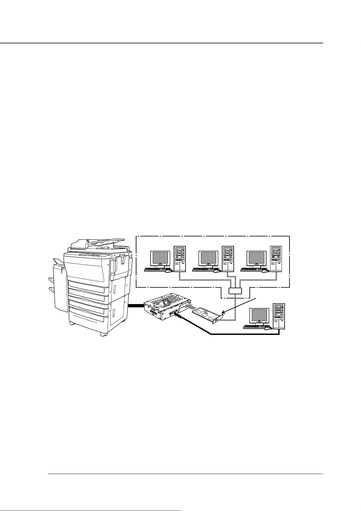
The print controller enables the copier connected to a computer or network to print from applications on Windows 95/98/Me or NT4.0/2000. To connect to a network, the optional network
interface card is required.
When the command for printing is executed from applications on Windows 95/98/Me or NT4.0/
2000, print data is sent to the print controller by way of a parallel cable (IEEE 1284) or a network. Then, the print controller rasterizes the print data to image data, which is sent to the
Printer Engine by way of the PCI bus.
The print controller can receive the command for printing from applications even while the
Printer Engine is printing the previous print jobs or receiving data.
The printing system can continuously print Letter/A4-size paper at a print speed of 45 ppm. In
addition, this system supports the duplex function and the finisher function which enables using
four paper trays, alternate printing and stapling.
Conceptual Connection
Chapter 1 Overview
Copier
Print Controller
When used as a network printer
Network Interface card
is required
When used as a local printer
E-RDH (Electronic Recirculating Document Handler)
The E-RDH is a system which temporarily saves print data in the memory of the copier to
enable printing in accordance with the selected option. To print from the print controller, the ERDH of the copier is used. The E-RDH memory of the copier is 32 MB (standard) and can be
extended to 288 MB maximum.
The E-RDH is used in the 1 bit mode. Data of approximately 180 pages of A4-size paper can be
saved in the 32 MB (standard) E-RDH memory.
Print Controller INSTRUCTION MANUAL 1-3
Page 15

Chapter 1 Overview
Copy Mode, Printer and Scanner Mode
Every mode of the copier operation panel can be used.
Even while the copier is printing or copying, the print controller can receive the next job, and
while the print controller is receiving a print job, you can perform copying.
Network Scanner
By installing the optional network interface card and hard disk on the print controller, image
data scanned by the copier is stored to the print controller’s hard disk and read into TWAINcompliant applications via a network. It can be also modified by this application.
Printer EKC
Printer EKC is a feature to manage the number of prints on the copier.
Setting the Printer EKC feature means that, provided you enter a password previously established on the printer to request a print job, the copier counts up printouts based on the EKC
counter to know when a preset limit is hit, and also rejects a print request from a client having
no valid password.
● Print Controller Hardware Configuration
Basic Configuration
Configuration of the print controller is as follows:
Control board
CPU: Pentium MMX- 266 MHz
Program memory: FLASH ROM (Compact Flash) 16 MB
System memory: 32 MB SD-RAM
Memory
The print controller is equipped with 32 MB memory as standard and can be expanded to 160
MB maximum.
● I/O Interface
Parallel
Centronics (IEEE1284)/ amphenol 36 pin male connector
PCI Bus
Card Edge Type/20 MHz/32 bit
Ethernet (option)
100Base-TX and 10Base-T
The optional network interface card is used to connect to the Ethernet. The network interface
card is the internal print server card which supports multiple protocols on the Ethernet. This
card includes a CPU and a flash memory with an upgradable program.
The network interface card supports the following network protocol.
• IPX/SPX (NetWare)
• TCP/IP (LPD/LPR, Peer to Peer )
Refer to the corresponding INSTRUCTION MANUAL for connection to the network interface
card.
1-4 Print Controller INSTRUCTION MANUAL
Page 16
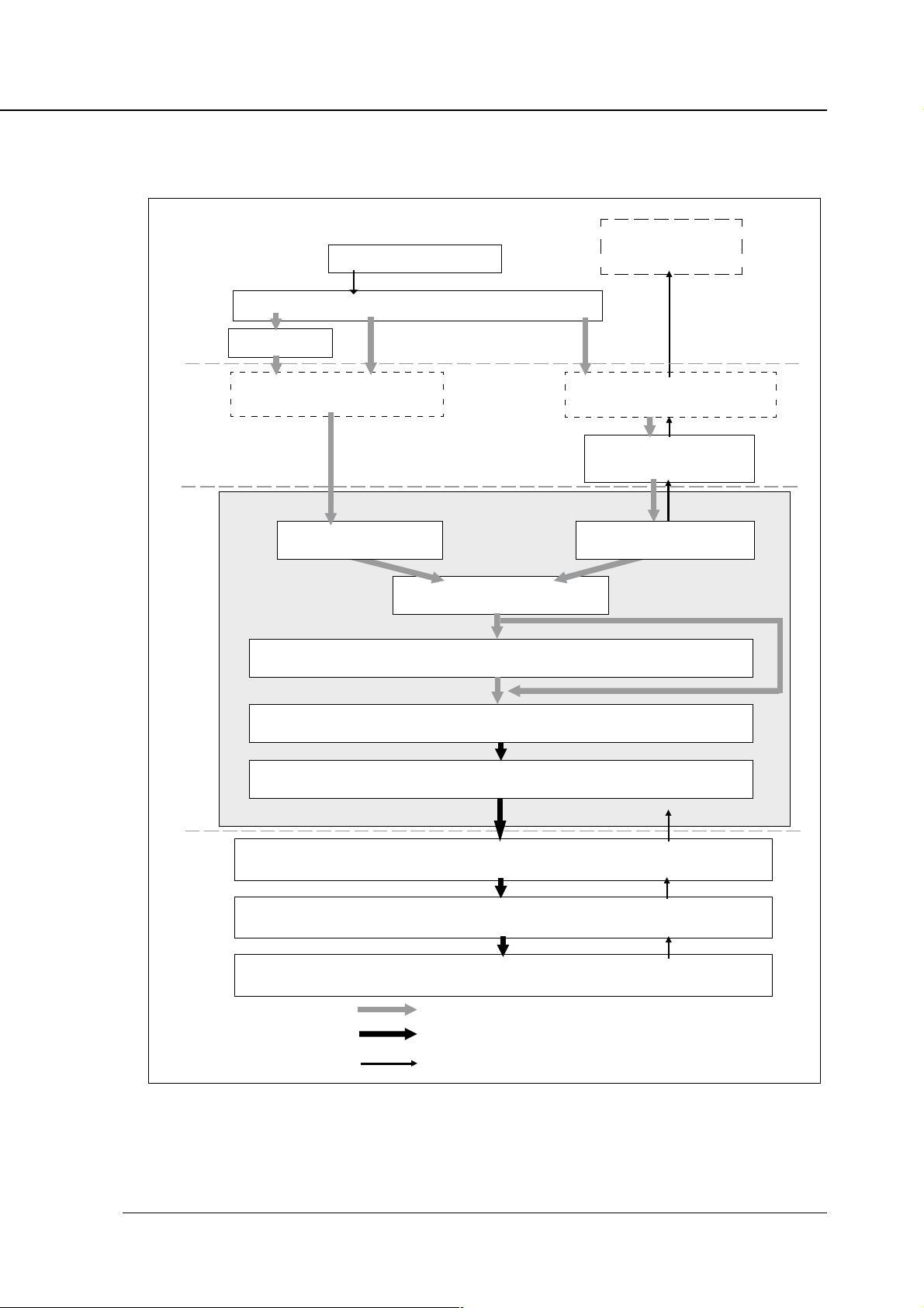
● Data Flow
Chapter 1 Overview
Print Commands
Spooler
Interface
Print Controller
Computer
Application
Printer Driver
Parallel I / F(IEEE1284)
Parallel I / F PCI bus
Browser
HTML
Ethernet I/F
(TCP/IP,IPX/SPX)
Network Interface Card
(Option)
Input Buffer
Hard Disk
(Option)
Printer Engine
PDL command
Rasterized image data
Printer status
PDL Processing(Rasterization)
Page memory
PCI bus
E-RDH memory
Engine(Print)
Print Controller INSTRUCTION MANUAL 1-5
Page 17

Chapter 1 Overview
● How to Use Memory
Most print controller memory is used for rasterizing images and the functions of cache and overlay,
only a small part of memory is used for system operation. In addition, the copier’s E-RDH memory is
used for print processing.
The basic memory setting of the print controller is 32 MB, which allows 1 bit mode (600 dpi) printing
for all paper sizes. The print controller memory can be expanded to 160 MB maximum. In addition, the
copier E-RDH can be expanded to 288 MB maximum.
The more memory included in the print controller, the more pages that can be rasterized while waiting
for printing of the previous job. When A4-size paper is used, approximately 4,345 KB memory is
required to print 1 bit data in 600dpi.
If you have a very complex page in a print job or if you frequently need to print out data on A3 or larger
size paper, memory errors may occasionally occur depending on the print controller’s memory size
available for rasterization (bitmap extracting process). In this case, it is recommended that you extend
the print controller’s memory.
When printing out data using Duplex print, Staple print or other advanced features, you need data of
the whole job rasterized by the print controller and stored in E-RDH memory. Therefore, when printing
a document with a very large number of pages, the data may be not print out according to the printing
features specified . To solve this problem, it is recommended that you expand the print engine’s
(copier’s) memory (E-RDH memory).
Memory Upgrading
To obtain optimum printer performance, memory expansion is recommended.
Contact your service representative for details.
1-6 Print Controller INSTRUCTION MANUAL
Page 18

Chapter 1 Overview
● General View
The print controller is mounted onto the copier. The following shows the general view from the front.
Print Controller
Network Interface Card
(option)
Parallel Port
Copier
The print controller is attached to
the rear side of the copier.
Print Controller INSTRUCTION MANUAL 1-7
Page 19

Chapter 1 Overview
■ About the Printer Driver
● Compliant OS
The printer driver can be used on the following OS.
Windows 95
Windows 98
Windows Me
Windows NT4.0
Windows 2000
Refer to “Chapter 2 Setup” (page 2-1) to learn how to install the printer driver.
Refer to “Chapter 3 Printer Driver” (page 3-1) for detailed functions of the printer driver.
1-8 Print Controller INSTRUCTION MANUAL
Page 20

Chapter 2 Setup
■ Contents of this Chapter ...................................... 2-2
■
Installation of the Printer Driver .....................................
● Before Installation ......................................................... 2-3
● Installing to Windows95/98/Me ..................................... 2-3
● Installing to WindowsNT4.0/2000 .................................2-4
● Uninstalling the Printer Driver ....................................... 2-6
■ Test Page ............................................................. 2-6
■ Print from Applications......................................... 2-7
● Execution of Printing ..................................................... 2-7
● Print Settings ................................................................2-7
■ Contents of Settings ............................................2-8
2-3
● Windows 95/98/Me ....................................................... 2-8
● Windows NT4.0/2000..................................................2-10
● Windows 2000 ............................................................ 2-12
Print Controller INSTRUCTION MANUAL 2-1
Page 21

Chapter 2 Setup
■ Contents of this Chapter
To use the printing system, connect the printing system to computers by way of the parallel port or
Ethernet port and install the printer driver in the computers. This chapter describes the installation of
the printer driver and explains how to print from applications.
Refer to “Parallel Port” (page viii) for detailed information on connecting to the parallel port.
Refer to “Chapter 3 Printer Driver” (page 3-1) for functions of the printer driver.
When the optional network interface card is added to the print controller, you must specify an appropriate network port, not an LPT1 (parallel port), to send output from the printer driver. For network
ports, consult the network administrator.
2-2 Print Controller INSTRUCTION MANUAL
Page 22

■ Installation of the Printer Driver
● Before Installation
Models and Computer Environment
The print controller for the copier can be used with Windows - based computers.
The print controller includes the printer driver for Windows95/98/Me and Windows NT4.0/2000.
The printer driver can be installed on any computer model installed with Windows95/98/Me or
Windows NT4.0/2000.
When installing the printer driver, a screen may appear that asks the user to select
whether the printer driver file (file to be copied) or a new file that exists in the computer
is to be used. If this screen appears, select use of a new file that already exists in the
computer. If a new file is not used, the OS may not start up properly the next time the
OS is started up.
Chapter 2 Setup
● Installing to Windows95/98/Me
Perform the following steps to install the Printer Driver to Windows 95/98/Me.
Please keep the “User Software CD” on hand since it is required to install the printer driver.
When an old version printer driver is installed, make sure to uninstall the driver before
installing the new printer driver.
Refer to [Uninstalling the Printer Driver] for instructions on uninstalling the printer driver.
1. Turn on the computer and start Windows.
When Windows applications are active, quit all of them.
2. Click the [Start] button of the task bar. Then, select [Settings] of the Start menu to
click [Printers] from the sub-menu.
The [Printers] window will open.
Opening from [My Computer]
You can open the [Printers] window by double-clicking the [Printers] folder after double
clicking the [My Computer] icon of the desktop.
Print Controller INSTRUCTION MANUAL 2-3
Page 23

Chapter 2 Setup
3. Double-click the [Add Printer] icon of the [Printers] window.
The [Add Printer Wizard] to install the printer driver will appear.
Then, follow the [Add Printer Wizard] to install the printer driver.
The PCL printer driver for Windows 95/98/Me is stored in the [Win9x] folder of the
[Printer] folder on the [User Software CD] (CD-ROM).
● Installing to WindowsNT4.0/2000
The installation of the printer driver in Windows 2000 or Windows NT4.0 should be performed by a
qualified system administrator or printer administrator.
The process of installing the printer driver necessitates the User Software CD. Get it ready in advance.
About Printer Administration under Windows 2000 or Windows NT4.0
Since Windows 2000 and Windows NT4.0 are operating systems intended for network operations, they offer more enhanced security options than in other Windows versions.
There are limitations to what you can operate or set up with their internal printers depending on
the selected security level (access authorization).
The table below provides an overview of the printer access authorizations and operational
limits.
sthgiRsseccA egnaRnoitarepO
sthgiRoN
• gnitnirpotdetalersnoitarepO
gnitnirP
• scihpargotdetalersnoitarepO
• snoitcnufretnirP
tnemucoD
• sgnittestnemucodfolortnoC
tnemeganaM
• stnemucodfonoiteleddna,gnitnirper,tratser,esuaP
• "tnemeganaMtnemucoD"dna"gnitnirP"follA
• stnemucodllafonoiteleddnaretnirpehtfotratserdnaesuaP
lortnoClluF
• noitamrofniretnirpfosegnahcdnasgnitteS
• retnirpehtfonoiteleD
• sthgirsseccaretnirpfosegnahcdnasgnitteS
.dewollaerasretnirpfosnoitarepooN
fosnoitidnoctnirpgniwollofehtdnagnitnirptnemucodfonoitucexE
.tesebotdewollaeratnemucodhcae
).cte,yartrepapdnaezisrepapafonoitceles(
).cte,enotflahdnanoituloserfognissecorp(
)reipocehtotrailucepsnoitcnuffonoitceles(
After installing the printer driver, set up an appropriate access authorization for the person
assigned to operate the printer.
For guidance in setting up the printer access authorization, refer to “System Guide” for Windows
2000 and Windows NT4.0.
2-4 Print Controller INSTRUCTION MANUAL
Page 24

Chapter 2 Setup
Installation Using [Add Printer]
In this method, only the printer driver is installed.
1. Turn on the computer and start Windows NT 4.0 or Windows 2000.
Exit from all active Windows applications, if required.
2. Log on as an administrator (or a user entitled to install the Power User, etc.).
3. Click the [Start] button of the task bar. Then, select [Settings] of the [Start] menu and
click [Printers] from the sub-menu.
The [Printers] window will open.
Opening from [My Computer]
Using Windows NT4.0
To open the [Printers] window, double-click the [Printers] folder after double clicking the
[My Computer] icon on the desktop.
Using Windows 2000
To open the [Printers] window, double-click the [Printers] folder after double clicking the
[Control Panel] folder in [My Computer] icon on the desktop.
4. Double-click the [Add Printer] icon of the [Printers] window.
The [Add Printer Wizard] to install the printer driver will appear.
Then, follow [Add Printer Wizard] to install the printer driver.
PCL printer driver for Windows NT4.0/2000 is stored in the [WinNT&2000] folder of the
[Printer] folder on the [User Software CD] (CD-ROM).
Print Controller INSTRUCTION MANUAL 2-5
Page 25
Chapter 2 Setup
● Uninstalling the Printer Driver
1. Quit all active Windows applications.
2.Click the [Start] button of the task bar. Then, select [Settings] of the Start menu and
click [Printers] from the sub-menu.
The [Printers] window will open.
3. Right-click the [Konica IP-431 PCL] icon.
4. Select [Delete].
5. Click the [Yes] button.
The printer driver will be uninstalled.
■ Test Page
You can check whether the printer driver functions properly by performing a test page after the printer
driver has been installed.
1. Click the [Start] button of the task bar. Then, select [Settings] of the Start menu and
click [Printers] in the sub menu.
The [Printers] window will open.
Opening from [My Computer]
Using Windows 95/98/NT4.0
To open the [Printers] window, double-click the [Printers] folder after double clicking the
[My Computer] icon on the desktop.
Using Windows 2000
To open the [Printers] window, double-click the [Printers] folder after double clicking the
[Control Panel] folder in [My Computer] icon on the desktop.
2. Right-click [Konica IP-431 PCL] and click [Properties].
[Konica IP-431 PCL Properties] will appear.
3. Select [General] of [Konica IP-431 PCL Properties] and click the [Print Test Page]
button.
A test print will start and a screen to confirm print end will appear.
4. Click the [Yes] button.
A test print will end.
2-6 Print Controller INSTRUCTION MANUAL
Page 26

■ Print from Applications
The method of printing depends upon you OS or applications. Printing with a Windows application is
explained bolow.
Please perform printing with an application using the "PCL printer driver" in the following procedure.
● Execution of Printing
1. Click the [File] menu of each application and click [Print].
2. Check that [Konica IP-431 PCL] is shown on [Printer Name] and click [OK].
When [Konica IP-431 PCL] is not shown, select it from the list box.
Setting the [Print] dialog box
Refer to the user's manual of each application.
Print settings of the printer driver
Refer to “Chapter 3 Printer Driver” for print settings of the printer driver.
Chapter 2 Setup
● Print Settings
Perform various settings at the time of printing on the printer driver setup screen.
Displaying the Setup Screen
1. Click the [File] menu of each application and click [Print].
2. Check that [Konica IP-431 PCL] is shown on [Printer Name] and click [Properties].
When [Konica IP-431 PCL] is not shown, select it from the list box.
[Konica IP-431 PCL on (Port Name) : Properties] will appear.
Print Controller INSTRUCTION MANUAL 2-7
Page 27

Chapter 2 Setup
■ Contents of Settings
The displayed screen depends on your OS. Certain tabs may not be displayed depending on settings.
For how to set the printer driver’s individual items, refer to “Chapter 3, Printer Driver Function List” .
● Windows 95/98/Me
Click [Start]-[Settings]-[Printers] so that the [Printers] window appears. Right-click on the Printer icon
in the resulting window. A menu will appear; you can click on [Properties] to access the Properties
window which looks like this:
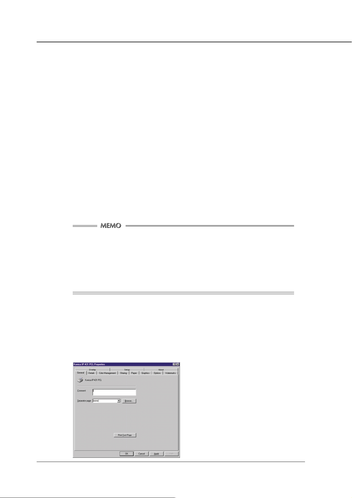
[General] tab
Comment / Separator page / Print Test Page
[Details] tab
[Paper] tab
Copies / Collate / Orientation / Offset / Staple / Combi-
nation / Front Cover / Back Cover / Cover Tray / Paper
Size / Media Type / Paper Source / Duplex / Output Tray
/ Password Print / Settings
[Graphics] tab
Print to the following port / Print using the following driver
/ Add Port / Delete Port / New Driver / Capture Printer
Port / End Capture / Timeout settings / Spool Settings /
Port Settings
2-8 Print Controller INSTRUCTION MANUAL
Solid Black and White / Patterned Grays / Diffused Grays
/ Brightness / Contrast / Negative
Page 28
Chapter 2 Setup
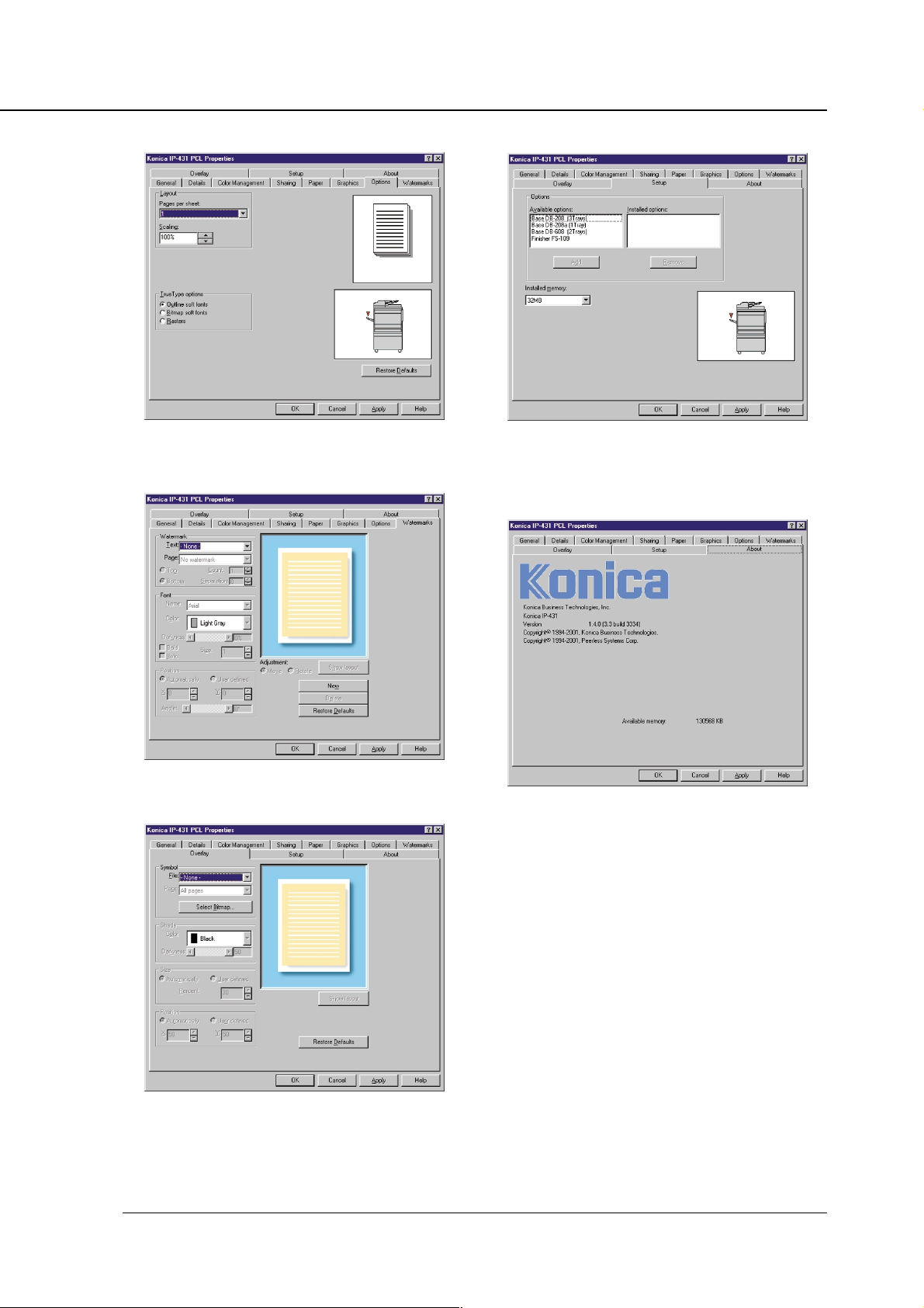
[Options] tab
Page per sheet / Scaling / TrueType options
[Watermarks] tab
[Setup] tab
Available options / Installed options / Installed memory
[About] tab
Watermark / Font / Position
[Overlay] tab
Symbol / Shade / Size / Position
Print Controller INSTRUCTION MANUAL 2-9
Page 29
Chapter 2 Setup
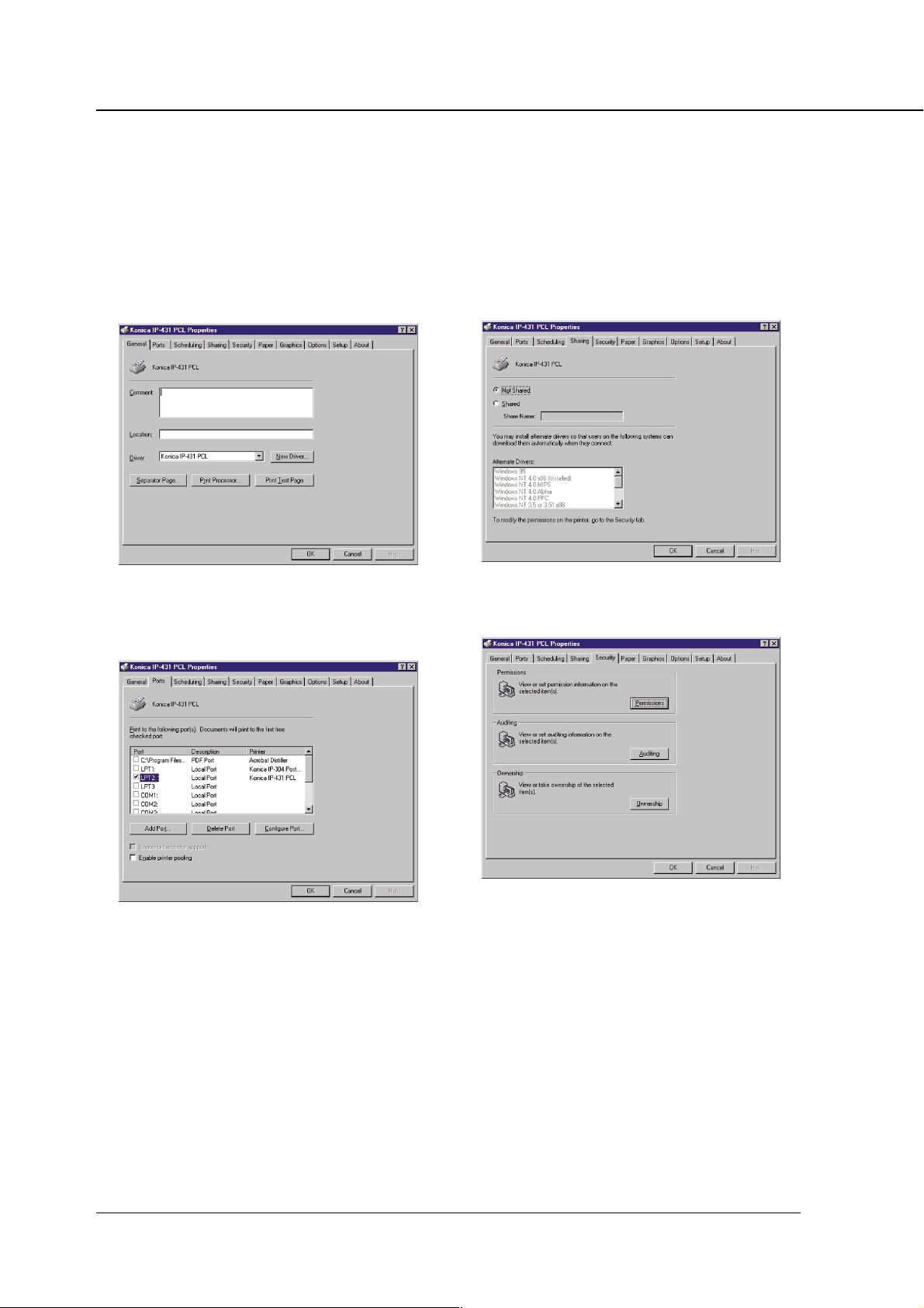
● Windows NT4.0
Click [Start]-[Settings]-[Printers] so that the [Printers] window appears. Right-click on the Printer icon
in the resulting window. A menu will appear, in which you can click on [Properties] or [Document
Defaults] to get access to the Properties window which looks like this:
[General] tab
Comment / Location / Driver / Separator Page / Print
Processor / Print Test Page
[Ports] tab
[Sharing] tab
Not Shared / Shared / Share Name / Alternate Drivers
[Security] tab
Add Port / Delete Port / Configure Port
2-10 Print Controller INSTRUCTION MANUAL
Permissions / Auditing / Ownership
Page 30

Chapter 2 Setup
[Paper] tab
Copies / Collate / Orientation / Offset / Staple / Combi-
nation / Front Cover / Back Cover / Cover Tray /Paper
Size / Media Type / Paper Source / Duplex / Output Tray
[Graphics] tab
[Setup] tab
Available options / Installed options / Installed memory
[About] tab
Solid Black and White /
/ Brightness / Contrast / Negative
Patterned Grays / Diffused Grays
[Options] tab
Outline soft fonts / Bitmap soft fonts / Rasters[About]
tab
Print Controller INSTRUCTION MANUAL 2-11
Page 31
Chapter 2 Setup
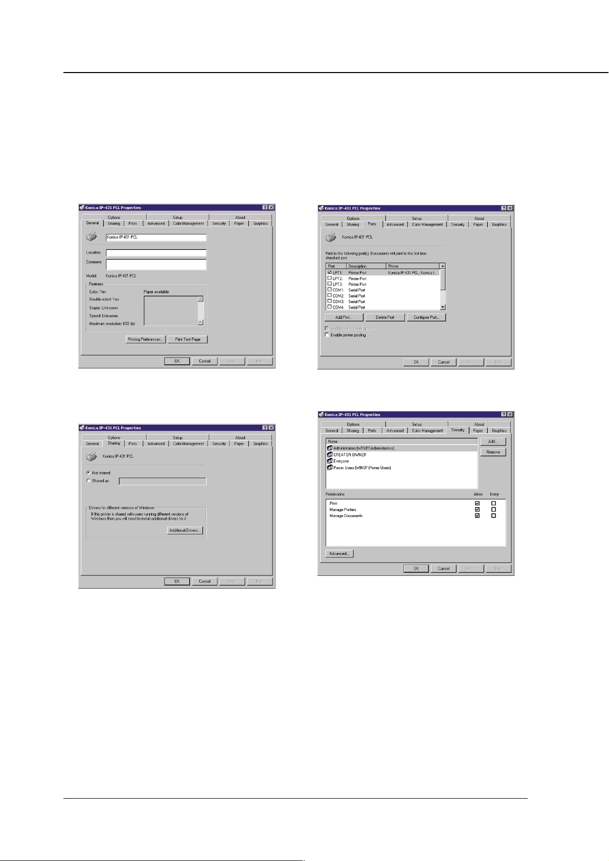
● Windows 2000
Click [Start]-[Settings]-[Printers] so that the [Printers] window appears. Right-click on the Printer icon
in the resulting window. A menu will appear, in which you can click on [Properties] or [Printing Preferences] to get access to the Properties window which looks like this:
[General] tab
Location / Comment / Printing Preferences / Print Test
Page
[Sharing] tab
[Ports] tab
Add Port / Delete Port / Configure Port
[Security] tab
Not shared / Shared as / Drivers for different versions of
Windows / Additional Drivers
2-12 Print Controller INSTRUCTION MANUAL
Name / Permissions / Advanced[Setup] tab
Page 32

Chapter 2 Setup
[Paper] tab
Copies / Collate / Orientation / Offset / Staple / Combi-
nation / Front Cover / Back Cover / Cover Tray / Paper
Size / Media Type / Paper Source / Duplex / Output Tray
[Graphics] tab
[Setup] tab
Available options / Installed options / Installed memory
[About] tab
Halftoning / Patterned Grays / Diffused Grays / Bright-
ness / Contrast / Negative
[Options] tab
Outline soft fonts / Bitmap soft fonts / Rasters
Print Controller INSTRUCTION MANUAL 2-13
Page 33

Chapter 3 Printer Driver
■ Contents of this Chapter ..................................... 3-2
■ Working Environment ......................................... 3-3
● Compliant OS ...............................................................3-3
■ Property of Printer Driver.................................... 3-3
■ Printer Driver Function List ................................. 3-7
■ Description of Printer Driver Functions ............. 3-10
Print Controller INSTRUCTION MANUAL 3-1
Page 34

Chapter 3 Printer Driver
■ Contents of this Chapter
This chapter fully describes the functions of the Printer Driver installed in computers connected to the
printing system. The Printer Driver functions are presented in two parts, listed first, then described
individually.
Refer to “Chapter 2 Setup” (page 2-1) for installation of the printer driver.
3-2 Print Controller INSTRUCTION MANUAL
Page 35

■ Working Environment
● Compliant OS
The Printer Driver can be used on the following OS.
Windows 95/98/Me
Windows NT4.0/2000
Refer to “Chapter 2 Setup” (page 2-1) for installation of the Printer Driver.
■ Property of Printer Driver
You have two ways of changing the settings of the printer driver.
One way is by selecting [Control Panel]-[Printers]-[Properties] of [Konica IP-431 PCL](or [Document
Defaults]-[Printing Preferences]). The other is by making settings within applications for each printing
session.
The settings made in the first way are effective on all printouts, whatever the application.
Chapter 3 Printer Driver
The settings made in the second way are effective only when the application for which they have been
made is running. When launching the application again, the settings made by going through [Control
Panel]-[Printers] are applied.
The display windows shown in this manual are those available with Windows95/98. They vary according to the OS in use. As well, among the tabs, there are some that are not displayed depending on
settings.
You can make the settings of the printer from applications with the exception of the settings on [General],
[Details], [Color management] and [Sharing] tabs in the [Konica IP-431 PCL] properties. For guidance
in setting the printer from applications, refer to “Chapter 2 Setup”(page 2-1).
For guidance in setting the printer from the copier control panel, refer to “Chapter 4 Control Panel
Setup” (page 4-1).
Print Controller INSTRUCTION MANUAL 3-3
Page 36

Chapter 3 Printer Driver
Windows 95/98/Me
1. Click [Start]-[Settings]-[Printers], right-click the [KONICA IP-431 PCL] icon, and then
click [Properties].
The following tabs will appear:
[General], [Details], [Color Management], [Sharing], [Paper], [Graphics], [Options], [Watermarks],
[Overlay], [Setup] and [About].
[OK]
When the [OK] button is clicked, all tab settings are saved and the properties screen is closed.
[Cancel]
When the [Cancel] button is clicked, all tab settings are canceled and the properties screen is
closed.
[Apply]
When the [Apply] button is clicked, the present tab settings are saved. This button is used when
settings continue to be performed by using other tabs, and the present tab settings are registered before using other tabs.
[Help]
When the [Help] button is clicked, Help for each tab will appear.
3-4 Print Controller INSTRUCTION MANUAL
Page 37

Chapter 3 Printer Driver
Windows NT4.0/2000
1. Click [Start]-[Settings]-[Printers], right-click the [KONICA IP-431 PCL] icon, and then
click [Properties].
The following tabs will appear, then settings of the printer ports and options should be made:
[General], [Ports], [Scheduling], [Sharing], [Security], [Paper], [Graphics], [Options], [Setup], and
[About].
2. Click [Start]-[Settings]-[Printers], right-click the [KONICA IP-431 PCL] icon, and then
click [Document Defaults] or [Printing Preferences].
The following tabs will appear:
[Paper], [Graphics], [Options], and [About].
[OK]
When the [OK] button is clicked, all tab settings are saved and the properties screen is closed.
[Cancel]
When the [Cancel] button is clicked, all tab settings are canceled and the properties screen is
closed.
[Apply]
When the [Apply] button is clicked, the present tab settings are saved. This button is used when
settings continue to be performed by using other tabs, and the present tab settings are registered before using other tabs.
[Help]
When the [Help] button is clicked, Help for each tab will appear.
Print Controller INSTRUCTION MANUAL 3-5
Page 38

Chapter 3 Printer Driver
Setting details of each tab
[General] tab
Enables a print test of a printer.
[Details] tab
Performs settings related to ports, drivers, timeout and spooling.
[Sharing] tab
Performs share settings of a printer.
[Paper] tab
Performs settings related to Copies, Collate, Orientation, Paper Size, Paper Source, Duplex
and Output Tray.
[Graphics] tab
Performs settings related to Halftoning, Brightness, Contrast and Negative.
[Options] tab
Performs settings related to Layout and True Type options.
[Watermarks] tab
For watermark settings.
[Overlay] tab
Performs settings related to Symbol, Shade, Size, and Position.
[Setup] tab
Performs settings related to optional accessories and installed memory.
[About] tab
This tab is used to show version information of the Printer Driver.
3-6 Print Controller INSTRUCTION MANUAL
Page 39

■ Printer Driver Function List
The following list summarizes functions (Setting items) which can be set by using the Printer Driver of
the printing system.
Refer to “■ Description of Printer Driver Functions” (page 3-10) for setting items of each function.
In addition, refer to “Chapter 2 Setup” (page 2-1) to learn how to perform printer settings from applications, “Chapter 4 Control Panel Setup” (page 4-1) and to learn how to perform printer settings from the
LCD panel.
noitacifissalCsmetIgnitteS eulaVteSnoitpircseD
Chapter 3 Printer Driver
batsliateD sgnittestuoemiT
detcelestoN
sgnitteStroP
tropgniwollofehtottnirP
gniwollofehtgnisutnirP
revird
troPretnirPerutpaC
erutpaCdnE -
troPddA
troPeteleD -
revirDweN -.revirdaddaotdesusinoitcnufsihT
-
.bojtnirp
1TPL/
eciveD
htaP
krowteN
rehtO
fotuoemittesotdesusinoitcnufsihT
yrternoissimsnarT
SOD-SMloopS
etatstropkcehC
.gnitnirperofeb
ELIF/2MOC/1MOC
.tropgnitnirpeht
.revirdretnirpeht
nogoltatcennoceR
.sretnirp
.tropyrassecennu
tesotdesusinoitcnufsihT
ehttaretnirpehtfohtapdna
.no-golfoemitehtta
.emitgnidneserdnatroplellarapeht
ehtrehtehwtesotdesusinoitcnufsihT
dnatonrodeloopssibojtnirpSOD-SM
sitrop:xTPLehtfosutatsehtrehtehw
.tonrognitnirperofebdekcehc
tcelesotdesusinoitcnufsihT
ecivedehttesotdesusinoitcnufsihT
krowtenafoyawybgnitnirpfoemit
demrofrepsinoitcennocerrehtehwdna
ehtraelcotdesusinoitcnufsihT
krowtenyrassecennufoshtapkrowten
.tropaddaotdesusinoitcnufsihT
naeteledotdesusinoitcnufsihT
ossbojtnirploopS
sehsinifmargorp
.retsafgnitnirp
ehtotyltceridtnirP
sgnitteSloopS
.retnirp
lanoitcerid-ibelbanE
.retnirpsihtroftroppus
lanoitcerid-ibelbasiD
.retnirpsihtroftroppus
.snoitcnuf
gniloopstesotdesusinoitcnufsihT
noitacinummoclanoitcerid-ibdna
Print Controller INSTRUCTION MANUAL 3-7
Page 40

Chapter 3 Printer Driver
noitacifissalCsmetIgnitteS eulaVteSnoitpircseD
batrepaP seipoC 999ot1
etalloC ffOronO
noitatneirO epacsdnaLrotiartroP
ezisrepaP
epyTaideM
ecruoSrepaP
xelpuD
yarTtuptuO 3ot1yarT,tluafeD
tesffO ffOronO
elpatS
noitanibmoC telkooB,enoN
revoCtnorF knalBrodetnirP,enoN
revoCkcaB knalBrodetnirP,enoN
yarTrevoC
tnirPdrowssaP -
sgnitteS -
batscihparG gninotflaH
ssenthgirB 001ot001-
tsartnoC 001ot001-
ehtyficepsotdesusinoitcnufsihT
.detnirpebotseipocforebmun
.segapelpitlumtuptuo
.noitatneiro
"5.8x"5.5
"11x"5.8
"41x"5.8
"71x"11
mm024x792-3A
mm792x012-4A
mm012x841-5A
mm453x052-4B
mm752x281-5B
mm281x821-6B
sehcni31x0.8-4F
mm093x762-K8
mm762x591-K61
nihT,repapnialP
,repapkcihT,repap
,)ycnerapsnarT(PHO
,)knalB(evaelretnI-PHO
)tnirP(evaelretnI-PHO
ot1yarT,tcelesotuA
yartssapyBro4
gnolnopilF,enoN
egde
egdetrohsnopilF
tfeLelgniS,enoN
,poTelbuoD
tfeLelbuoD
,2yarT,1yarT,enoN
ro4yarT,3yarT
yartssapyB
,etihWdnakcalBdiloS
rosyarGdenrettaP
syarGdesuffiD
.sliated
.yartssap
.yartrepap
.gnitnirpxelpuD
.yarttuptuo
.edom
.noitisopelpats
.tuoyal
.desuera
.desuera
.srevoc
.golaid]sgnitteStnirP
.noitropenotflah
.gninotflahnotnemtsujda
.gninotflahnotnemtsujda
otwohyficepsotdesusinoitcnufsihT
yficepsotdesusinoitcnufsihT
reffidtesnacuoysezisrepapehT
ehtnisnoitacificepsnognidneped
ehtotrefeR.syartdnayrtnuoc
rofreipocehtfolaunamgnitarepo
ehtyficepsotdesusinoitcnufsihT
-yBehtmorfdetnirpebotepytrepap
ehtyficepsotdesusinoitcnufsihT
foedomehttesotdesusinoitcnufsihT
ehtyficepsotdesusinoitcnufsihT
tesffoyficepsotdesusinoitcnufsihT
ehttcelesotdesusinoitcnufsihT
egapegnarraotdesusinoitcnufsihT
srevoctnorfnehwdesusinoitcnufsihT
srevockcabnehwdesusinoitcnufsihT
repapatcelesotdesusinoitcnufsihT
kcabdnasrevoctnorfrofdesuecruos
ehttesotdesusinoitcnufsihT
.)tuptuolaitnedifnoc(tnirpdrowssap
drowssaP[nepootnottubsihtsserP
.drowssapdnaDIresUruoyretnE
ehttcelesotdesusinoitcnufsihT
rofgnissecorpegamiehtfodohtem
naekamotdesusinoitcnufsihT
naekamotdesusinoitcnufsihT
3-8 Print Controller INSTRUCTION MANUAL
Page 41

noitacifissalCsmetIgnitteS eulaVteSnoitpircseD
Chapter 3 Printer Driver
evitageN ffOronO
bat
skramretaW
batsnoitpO teehsrepsegaP 61,21,9,6,4,2,1
batyalrevO eliF -
txeT
egaP
gnilacS %004-01
egaP
noitpoepyTeurT
pamtiBtceleS -
.enotesrever
,LAITNEDIFNIC,enoN
motsuC,YPOC
,TFARD,1kramretaw
,FOORP
,LANIF,YPOCELIF
TERCESPOT
llA,egaptsriftubllA
egaptsriF,segap
kramretaWoN,ylno
,stnoftfoseniltuO
,stnoftfospamtiB
sretsaR
,egaptsriftubllA
egaptsriF,segapllA
yalrevooN,ylno
.detnirpeblliw
.dekramretawebot
.repapfo
.stnofepyTeurTtuptuo
.detnirpsi
.yalrevorofegami
htiwegamitnirpotdesusinoitcnufsihT
tsil]txeT[ehtnidetceleskramretawehT
segaptcelesnacresuehttsilehtmorF
nahteromtnirpotdesusinoitcnufsihT
teehsenonotnemucodafoegapeno
rodecuderegamitnemucodehtstnirP
.eulavdeificepsehtotdegralne
otwohyficepsotdesusinoitcnufsihT
nayficepsotdesusinoitcnufsihT
.repapnodetnirpmrofyalrevo
ehtyficepsotdesusinoitcnufsihT
mrofyalrevodetcelesahcihwnoegap
pamtiBretsigerotdesusinoitcnufsihT
roloC kcalB
ssenkraD 001ot0
eziS
noitisoP
batputeS snoitpoelbaliavA
yromemdellatsnI
battuobA - -
srehtO stluafeDerotseR -
.elbatceles
yllacitamotuA
denifedresU
)001ot01(
yllacitamotuA
denifedresU
)001ot0(
]syarT3[802-BDesaB
]yarT1[A802-BDesaB
]syarT2[806-BDesaB
901-SFrehsiniF
/BM46/BM23
BM061/BM69
.egatnecrep
.yromemdellatsni
sikcalBylnO.egamipamtiba
yficepsotdesusinoitcnufsihT
.egamiyalrevofonoitisop
.revirDretnirPehtfonoitamrofni
ehtnruterotdesusinoitcnufsihT
.sgnittestluafedotsgnittes
For tabs that are not mentioned on this page, refer to the Windows instruction manual.
rofrolocyficepsotdesusinoitcnufsihT
.yalrevorofegamipamtibfossenkraD
ehtyficepsotdesusinoitcnufsihT
niegamiyalrevofoetarnoitacifingam
ehtyficepsotdesusinoitcnufsihT
ehtyficepsotdesusinoitcnufsihT
.reipocehtnodellatsniecivedlanoitpo
ehtyficepsotdesusinoitcnufsihT
noisrevwohsotdesusinoitcnufsihT
Print Controller INSTRUCTION MANUAL 3-9
Page 42

Chapter 3 Printer Driver
■ Description of Printer Driver Functions
Functions (setting items) which can be set with the Printer Driver are summarized in the tab order.
These settings can be set by using [Start]-[Settings]-[Printers]- [Konica IP-431 PCL] property. The
tabs in this section are those in the [Konica IP-431 PCL] property.
[General] tab
Comment
You can input a comment in this column.
Separator page
This function is used to specify the separator page.
[Details] tab
Print to the following port
Select the printing port of the print controller from the list shown by clicking the [▼] button
beside [Details] tab-[Print to the following port] box. Select a printing port from [FILE], [LPT1]
and so on.
Print using the following driver
Select the driver used for printing from the list shown by clicking the [▼] button beside [Details]
tab-[Print using the following driver] box. When a driver is changed, settings of presently shown
properties are saved and the properties of the newly selected driver will appear.
Add Port
When the port you would like to connect to is not shown on the list shown by clicking the [▼]
button beside the [Details] tab-[Print to the following port], click [Details] tab-[Add Port] button to
add the port.
When the [Add Port] button is clicked, the [Add Port] dialog is shown.
The following settings are performed on the [Add Port] dialog;
When [Network] is selected to set a path to a network printer, you can add a network
printer to a port.
When [Others] is selected to select the type of a port to be added, you can add the port
selected from a list.
Delete Port
When a port is specified on the [Delete Port] dialog shown by clicking [Details] tab-[Delete Port]
button, and the [OK] button is clicked, you can delete the specified port.
3-10 Print Controller INSTRUCTION MANUAL
Page 43

Chapter 3 Printer Driver
New Driver
Click the [Details] tab, then click the [▼] button next to the field [Print using the following driver]
to display the list of available print drivers. To use a print driver not listed, click the [New Driver]
button. When a driver is changed, the settings of presently shown properties are saved and the
properties of a newly selected driver is shown.
Capture Printer Port
When the device name and path are specified on the [Capture Printer Port] dialog shown by
clicking [Details] tab-[Capture Printer Port] button, a network printer can be allocated as a
virtual printer port.
In addition, when [Reconnect at Logon] of the [Capture Printer Port] dialog is selected, a virtual
printer port is automatically reconnected at log-on.
End Capture
When the virtual printer port is specified on the [End Capture] dialog shown by clicking [Details]
tab-[End Capture] button, you can delete a network printer allocated as a virtual printer port.
Timeout settings
By using [Details] tab-[Timeout Settings], the timeout value is set.
Not selected
The [Not Selected] box indicates the number it will take in seconds for a printer to become
available for printing, from the time the computer starts outputting print data. If the waiting time
exceeds the value set, a printer error is shown and the job is automatically cancelled.
Transmission retry
The [Transmission retry] box is used to set the amount of time in seconds until a printer is to
become available for printing and allow a computer that failed to output once to output the print
data again. If the waiting time exceeds the set value, a printer error is shown and the job is
automatically cancelled.
Spool settings
Set the method of spooling (temporary saving) the print data when it is sent to the printer on the
[Spool Settings] dialog shown by clicking [Details] tab-[Spool Settings] button.
Spool print job so program finishes printing faster
When [Spool print jobs so program finishes printing faster] is selected, Spool is set to on.
You may select either [Start printing after last page is spooled] or [Start printing after first page
is spooled] as a method of spooling.
When [Start printing after last page is spooled] is selected, it is possible to edit other
documents and start up other applications while printing, since print data is sent to a
printer after the printing process of applications has been completed.
When [Start printing after first page is spooled] is selected, print data is spooled page by
page and sent to a printer. Although this takes more time for an application to be released
from the printing process, this method is suitable in the event that free space for spooling
in your hard disk is small.
Print Controller INSTRUCTION MANUAL 3-11
Page 44

Chapter 3 Printer Driver
Spool data format
Select [Spool data format] either from EMF or RAW.
Print directly to the printer
When [Print directly to the printer] is selected, a print job is sent directly to the printer without
spooling it.
Port Settings
Click [Detail] tab-[Port Settings] button to perform settings of the port selected on the [Print to
the following port] box.
When the “LPT” is selected, the [Configure LPT Port] dialog is shown by clicking the [Port
Settings] button. The following settings are performed on the [Configure LPT Port] dialog.
When [Spool MS-DOS Print Job] is selected, a MS-DOS print job is spooled.
When [Check port state before printing] is selected, the port status is checked before
printing.
[Sharing] tab
Shared As
By using the [Sharing] tab, you can select to share a printer. Refer to your Windows manual for
printer sharing.
[Paper] tab
Copies
Click the [▲] or [▼] button or directly enter the number of copies from the keyboard.
Default is 1.
Collate
This function is used to specify how to output multiple pages.
Default is ON. It is recommended that you select [Collate] ON on the [Paper] tab rather than
select it for each application.
collate on collate off
3-12 Print Controller INSTRUCTION MANUAL
Page 45

Orientation
This function is used to specify orientation.
Default is Portrait.
Paper size
Select the paper size from the list shown by clicking the [▼] button.
Default is [A4 -210 x 297mm].
The paper size you can select is as follows:
detcelesebotezisrepaP
5.5" 5.8x"
11x"5.8"
"41x"5.8
"71x"11
mm024x792-3A
mm792x012-4A
mm012x841-5A
mm453x052-4B
mm752x281-5B
mm281x821-6B
sehcni31x0.8-4F
mm093x762-K8
mm762x591-K61
Chapter 3 Printer Driver
Refer to your Copier INSTRUCTION MANUAL for paper sizes that can be used in each tray.
Media Type
Select the paper type from the list shown by clicking the [▼] button.
Default is [Plain paper].
The settings you can select are as follows:
[Plain paper], [Thin paper], [Thick paper], [OHP(Transparency)], [OHP-Interleave(Blank)],
[OHP-Interleave(Print)]
Paper Source
Select the paper source from the list shown by clicking the [▼] button.
Default is [Auto Select].
When [Auto Select] is selected, a paper tray with paper which a user specified from an application by using [Konica IP-431 PCL on (Port name) : Properties] is automatically selected.
Print Controller INSTRUCTION MANUAL 3-13
Page 46

Chapter 3 Printer Driver
Duplex
Select the Duplex setting from the list shown by clicking the [▼] button.
Default is [None].
The settings you can select is as follows:
[None], [Flip on long edge], [Flip on short edge]
[Flip on long edge]
Prints paper so that heads of
both sides become upward
[Flip on short edge]
Prints paper so that the head
of the front becomes the foot
of the back.
Output Tray
Select an output tray from the list shown by clicking the [▼] button. When the Finisher option is
not selected in [Setup] tab, or when the Finisher is not installed, any setting other than [Default]
and Tray 1 is ineffective.
Features
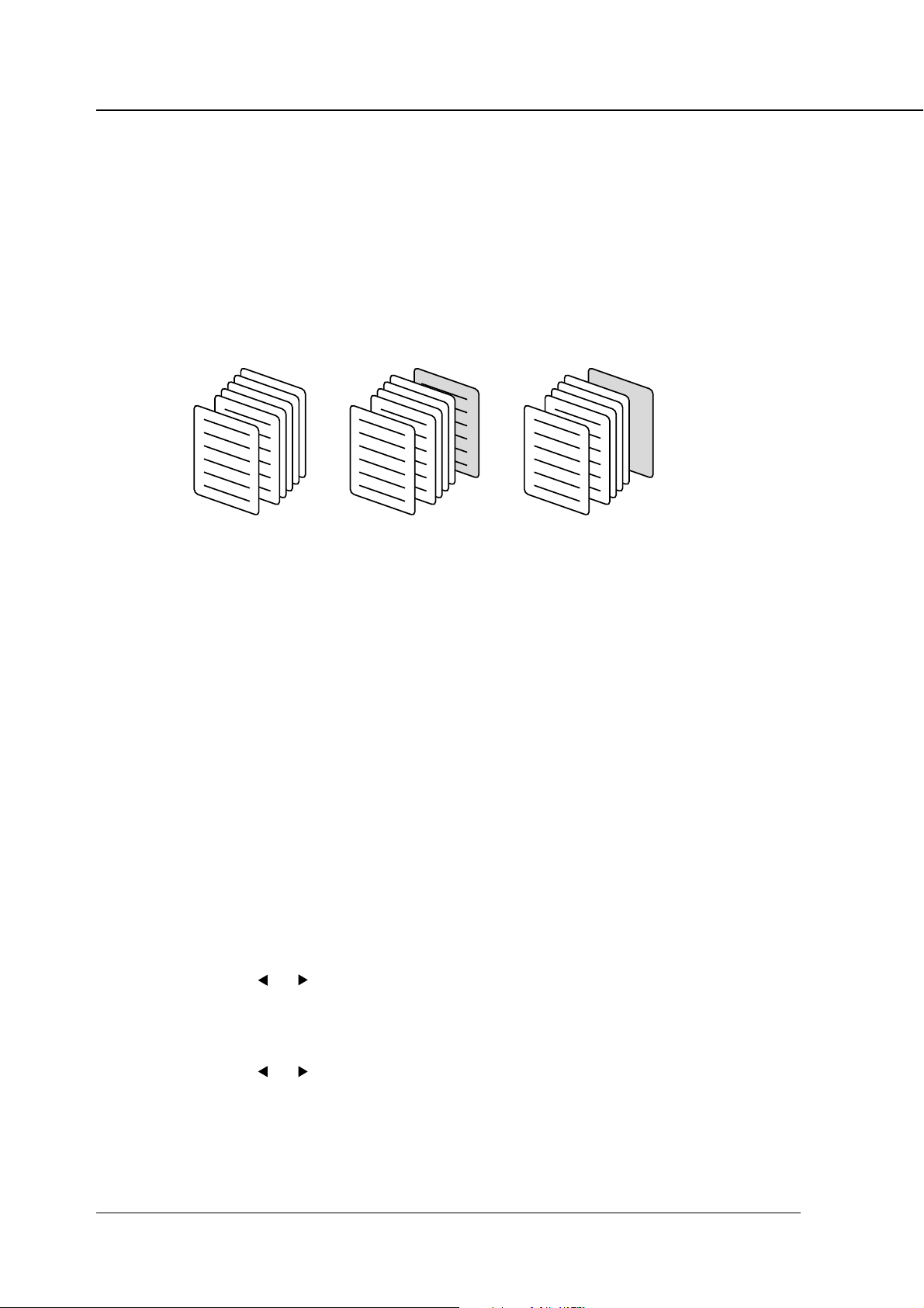
Offset
[ON] offsets each copied set upon exit.
How to offset papers differs depending on wether the Finisher is installed or not.
Example)
Three sets
Two sets
One set
None
Without Finisher
• When the Finisher is not installed, every set of copies is output in a direction at right angles
to the previous set of copies.
• When the Finisher is installed, every set of copies is offset upon exit.
Three sets
Two sets
One setOne set
Two sets
Three sets
With Finisher
When the Finisher is not installed, make sure to set the papers same as printing paper
size to both portrait tray and landscape tray.
(Example: A4- and A4R-size papers or B5- and B5R-size papers)
In the case of “with” Finisher (FS-109), [Tray 1] is not available.
3-14 Print Controller INSTRUCTION MANUAL
Page 47
Chapter 3 Printer Driver
To select offset click [Features - Offset] from the list shown by using the [▼] button.
Default is [Off].
Staple
To select the Staple position click [Features - Staple] from the list shown by using the [▼]
button.
The settings you can select are as follows:
[None], [Single-Left], [Double Top], [Double Left].
Default is [None].
However, the settings of Staple cannot be made in the following cases:
• [Finisher] is not selected.
• OHP (Transparency), OHP-Interleave (Blank) or OHP-Interleave (Print) are selected
as the Media Type.
• [Default] or [Tray 1] is selected in the [Output Tray] setting.
• Such a combination of settings as follows is made:
(Example: Double Left for A3-size paper (portrait)
For details on how to position the Staple, refer to the Instruction Manual of the copier.
Stapling is performed as shown for the following orientations:
2-point stapling not available with papers of A5 size and under.
Single Left (portrait) Double Top (portrait) Double Left (portrait)
Single Left (Landscape) Double Top (Landscape) Double Left (Landscape)
Unavailable with A5-size paper
Print Controller INSTRUCTION MANUAL 3-15
Page 48

Chapter 3 Printer Driver
Password Print
When [Password Print] is checked, you can use the password print function to print confidential
documentation.
In this method, both settings on computer and the operation from the LCD touch panel are
used. Default is [Off].
Refer to “Chapter 4 Password Print ” (page 4-11) for password print procedures.
Data saved to the copier for Password Print is automatically deleted 24 hours later if
not output during this interval.
Settings
Open the [Password Print Settings] dialog for password setting.
Enter your user ID in the [User ID] text box. You can select any 5-digit number for the User ID.
Enter your password in the [Password] text box. You can select any 8-digit character for the
Password.
Providing the Printer EKC feature has been set on the copier, [User ID] set up in the
[Settings] dialog is recognized for a password for Printer EKC.
Provided a Printer EKC feature has been set on the copier, you can enter the same
number in the [User ID] text box as that representing your password for Printer EKC.
For Printer EKC, refer to “ Chapter 6 Printer EKC ”.
3-16 Print Controller INSTRUCTION MANUAL
Page 49

Chapter 3 Printer Driver
Combination
To select Combination click [Features - Combination] from the list shown by using the [▼]
button.
The settings you can select are as follows:
[None], [Booklet]
Default is [None].
Booklet
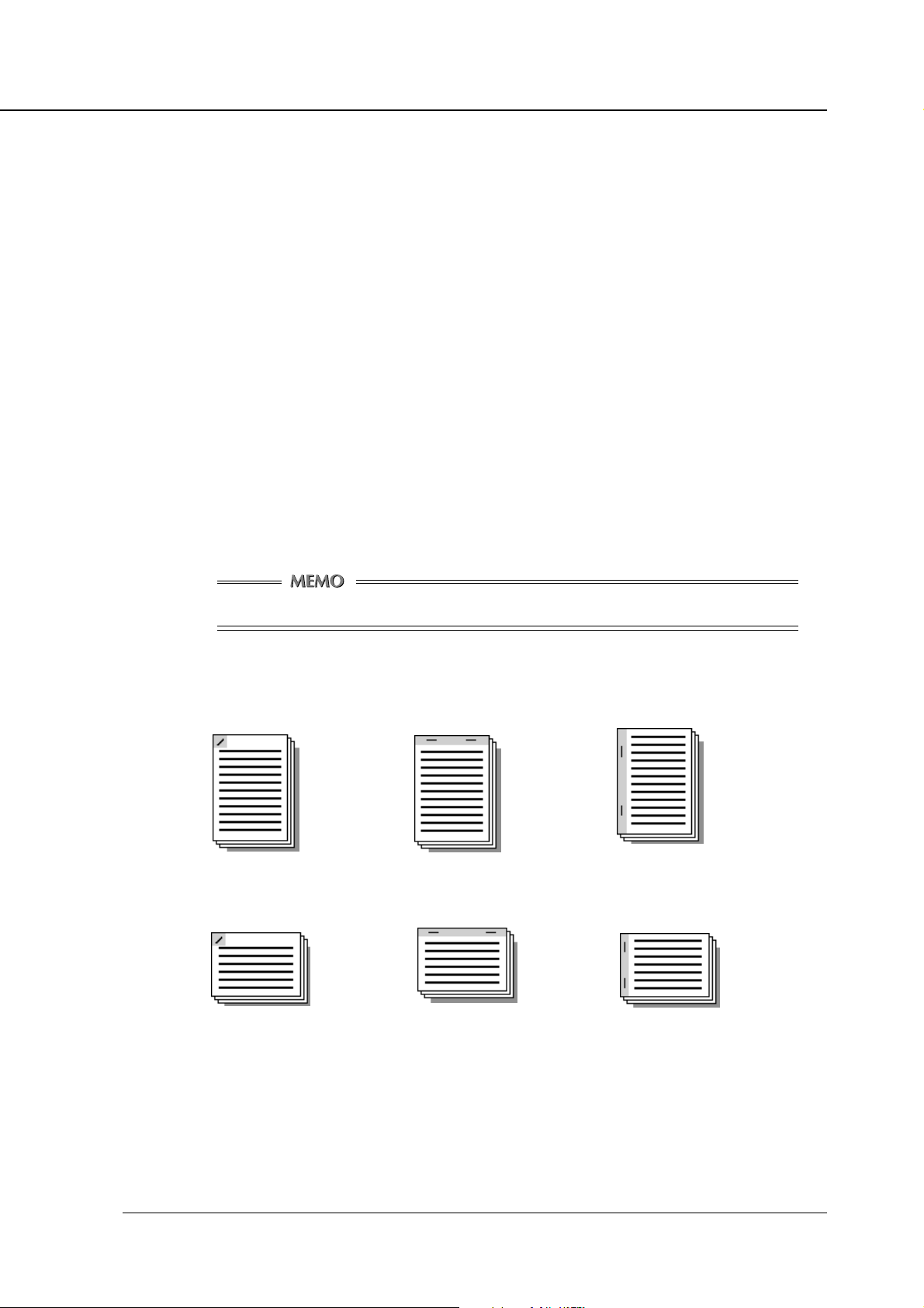
Front Cover
To select Front Cover click [Features - Front Cover] from the list shown by using the [▼] button.
The settings you can select are as follows:
[None], [Printed], [Blank]
• When [Blank] is selected, nothing is printed on the Front Cover.
• When [Printed] is selected, the first page is printed on the front cover.
[None] [Printed] [Blank]
Default is [None].
The tray for covers is selected by using [Features - Cover Tray].
The front cover settings cannot be made in the following cases:
• [Booklet] is set up.
• Options other than [Plain paper] are selected as Media Type.
• The Sort setting is set to OFF.
Print Controller INSTRUCTION MANUAL 3-17
Page 50
Chapter 3 Printer Driver
Back Cover
To select Back Cover click [Features - Back Cover] from the list shown by using the [▼] button.
The settings you can select are as follows:
[None], [Printed], [Blank]
• When [Blank] is selected, nothing is printed on the Back Cover.
• When [Printed] is selected, the last page is printed on the back cover.
[None] [Printed] [Blank]
Default is [None].
The tray for covers is selected by using [Features - Cover Tray].
Cover Tray
To select Cover Tray click [Features - Cover Tray] from the list shown by using the [▼] button.
The settings you can select are as follows:
[None], [Bypass tray], [Tray 1], [Tray 2], [Tray 3], [Tray 4]
Default is [Bypass tray].
[Graphics] tab
Halftoning
Select the Halftoning setting by clicking the desired options.
The settings you can select are as follows:
[Solid Black and White], [Patterned Grays], [Diffused Grays]
Default is [Patterned Grays].
Brightness
Click the [ ] or [ ] button or enter the setting directly from the keyboard.
Default is 0.
Contrast
Click the [ ] or [ ] button or enter the setting directly from the keyboard.
Default is 0.
Negative
[Negative] prints image with reverse tone.
Default is off.
3-18 Print Controller INSTRUCTION MANUAL
Page 51

[Options] tab
Layout
Pages per sheet
You can select the number of document pages to be printed on one piece of paper.
To select the Pages per sheet click [Layout - Pages per sheet] from the list shown by using the
[▼] button.
The settings you can select are as follows:
[1], [2], [4], [6], [9], [12], [16]
Default is 1.
[1] [2] [4]
Chapter 3 Printer Driver
[6] [9] [12]
[16]
Print Controller INSTRUCTION MANUAL 3-19
Page 52

Chapter 3 Printer Driver
Scaling
Scaling is at 100% by default.
The setting can be changed in the range of 25% to 400% in 1% increments.
TrueType options
Select the desired TrueType setting from the following options.
[Outline soft fonts] prints documents using a TrueType font which downloaded from your computer using outline data format.
[Bitmap soft fonts] prints documents using a TrueType font which downloaded from your computer using bitmap data format.
[Rasters] is selected, all text and font data is converted in the computer into Raster graphics
and downloaded to the printer.
The settings you can select are as follows:
[Outline soft fonts], [Bitmap soft fonts], [Rasters]
Default is [Outline soft fonts].
[Overlay] tab
Symbol
File
The bitmap files used for the overlay will appear in the list shown by clicking the [▼] button. If
you have not selected any file, the list will display [-None-]. Select a file from this list or click the
[Select Bitmap] button to navigate through your system’s hard disk to locate a bitmap file to use.
Default is [None].
Page
You can choose a page on which to place the overlay design.
To select the Page setting of Symbol File click [Symbol - Page] from the list shown by using the
[▼] button.
The settings you can select are as follows:
[All but first page], [All pages], [First page only], [No overlay]
Default is [All pages].
Select Bitmap
When you click the [Select Bitmap] button, the [Open overlay file] dialog box will appear. Select
a suitable bitmap file for the overlay from your system’s directories and click the [OK] button to
load the bitmap file.
3-20 Print Controller INSTRUCTION MANUAL
Page 53

Chapter 3 Printer Driver
Shade
Color
This function is used only for black and white (monochrome) bitmaps.
Darkness
You can define how “dark” or “solid” your overlay will be with the slider or numerical entry box. A
setting of 100% is a completely solid overlay, a setting of 50% provides equal overlay to background coverage, and lesser settings make the overlay more transparent.
Size
When [Automatically] is selected, a symbol you selected will be resized to 30% of the page
size.
When [User defined] is selected, you can set the overlay size on the page.
Position
You can control the position of the overlay on the page manually or leave it at the automatic
setting and let the driver position it for you.
If you select [User defined], you can define the X axis position (left and right) and Y axis position
(up and down) of the overlay on the page by clicking the [▲] or [▼] button or by entering the
values directly from the keyboard (0-100).
[Setup] tab
Options
Available options
This list shows available printer options. If you purchase this optional accessory you can make
the printer driver “aware” of it by selecting it from this list and clicking the [Add] button. The
selected option’s label will jump over into the list of [Installed options].
Installed options
This list displays the selected options from the list of [Available options].
Installed memory
Select the Installed memory from the list shown by clicking the [▼] button.
The settings you can select are as follows:
[32 MB], [64 MB], [96 MB], [160 MB]
Default is [32 MB].
[About] tab
The [About] tab shows some system information and the Printer Driver version.
Print Controller INSTRUCTION MANUAL 3-21
Page 54

Chapter 4 Control Panel Setup
■ Contents of this Chapter ...................................... 4-2
■ About the Control Panel ...................................... 4-3
● The Copier Control Panel.............................................. 4-3
● How to Enter Settings on the LCD Panel ...................... 4-4
● Printer Mode Basic Screen ........................................... 4-4
● Printer Menu Screen ..................................................... 4-5
● Editing Print Jobs .......................................................... 4-6
● Procedures of the Printer Setting.................................. 4-6
■ Configuration of Printer Setting Menu ................. 4-7
■ Functions of the Printer Setting ...........................4-8
● Test Print Menu .............................................................4-8
● Controller Set ................................................................ 4-8
● Set Default .................................................................... 4-9
● PCL Setup .................................................................. 4-10
● Password Print ............................................................ 4-11
● Format HD ..................................................................4-12
■ Key Operator Settings ....................................... 4-13
● To enter Key Operator mode: ...................................... 4-13
● Setting Items ............................................................... 4-13
Print Controller INSTRUCTION MANUAL 4-1
Page 55

Chapter 4 Control Panel Setup
■ Contents of this Chapter
This chapter describes the printer mode basic screen, the setup menu and Key operator menu of the
Copier Control Panel. Refer to the INSTRUCTION MANUAL of the copier for other functions and
screens of the Control Panel.
Refer to “Chapter 2 Setup” (page 2-1) to learn how to use the Printer Driver from applications, “Chapter 3 Printer Driver” (page 3-1) to learn how to set the printer from the Printer Driver and
“Chapter 5 Scanner” (page 5-1) to learn how to use the Scanner.
4-2 Print Controller INSTRUCTION MANUAL
Page 56

■ About the Control Panel
● The Copier Control Panel
[CHECK] button
[SCANNER] button
SCANNER/PRINTER
LED
HELP
CHECK
APPLICATION
OUTPUT
JOB MEMORY
AUTORESET
Chapter 4 Control Panel Setup
[PRINTER] button DATA LED
SCANNER
123
456
789
0
PC
CLEAR QTY
PROOF COPY
COPYPRINTER
INTERRUPT
START
DATA
POWER SAVER
STOP/CLEAR
TIMER
ON/OFF
LCD Panel
[AUTO RESET] button
[STOP/CLEAR] button
[SCANNER] button
Switches to the scanner mode.
[PRINTER] button
Switches to the printer mode.
LCD Panel
Displays the status of the Print controller, setting menus and setting options.
[CHECK] button
Displays the copier CHECK screen setting on the LCD Panel.
[AUTO RESET] button
Resets the copier settings to default settings.
[STOP/CLEAR] button
Cancels the currently processing copy or print process.
DATA LED
When the Print Engine is receiving data this LED flashes in green.
When the Printer Engine is not receiving data, but data is stored in its memory, the LED is
steadily lit.
SCANNER/PRINTER LED
This LED turns green in the scanner/printer mode and turns red when a warning message or an
error message is issued. In such a case, the print process is interrupted. Operations by an
operator or a service is required. Check the error information on the LCD Panel. When the
cause of the error is removed, the print process starts again.
Print Controller INSTRUCTION MANUAL 4-3
Page 57

Chapter 4 Control Panel Setup
● How to Enter Settings on the LCD Panel
Enter settings from the printer mode basic screen shown on the LCD Panel by using either the item
selection or the information entry.
Item Selection
In this method, various settings are performed by selecting a button with a number that corresponds to the item you would like to select on the LCD Panel.
Currently Selected Items
Currently selected items are reverse color.
[Cancel]
Pressing the [Cancel] key returns you to the last screen without saving your settings.
[OK]
Pressing the [OK] key saves your settings and returns you to the last screen.
● Printer Mode Basic Screen
When the printing system starts properly, the printer mode basic screen is displayed on the
LCD Panel by pressing the [PRINTER] button.
The Scanner Mode Basic Screen is displayed on the LCD Panel by pressing the [SCANNER]
key.
Refer to “Chapter 5 Scanner”(page 5-1) for information on using the scanner.
4-4 Print Controller INSTRUCTION MANUAL
Page 58
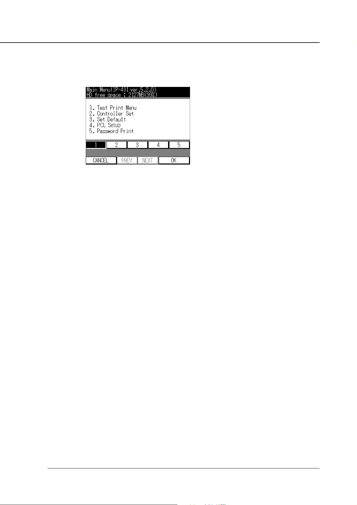
● Printer Menu Screen
The following printer menu screen is displayed by pressing the [Setting] key on the printer mode
basic screen.
When the [COPY] button is pressed again, the LCD Panel is changed to the copy mode basic
screen, and the normal copy settings become available.
[1. Test Print Menu]
You can print out the PCL Demo page, PCL Font List and Config. Data.
Chapter 4 Control Panel Setup
[2. Controller Set]
You can set up Banner page, Spool, Job Time Out and Scan Data Auto Del.
[3. Set Default]
You can set up the default value of Paper size, Duplex and Orientation.
[4. PCL Setup]
Display the PCL Setup Screen.
You can perform various settings related to PCL.
[5. Password Print]
The password print job to be set up from the printer driver is printed after entering the password
from the LCD touch screen.
[6. Format HD]
Format a hard disk.
Print Controller INSTRUCTION MANUAL 4-5
Page 59

Chapter 4 Control Panel Setup
● Editing Print Jobs
When [Copy] - [Job List] key on the printer menu screen is selected, the Job List screen is displayed.
Delete the Print jobs.
1. Press the [ / ] key to select the print job.
2. Press [DELETE] key.
Print jobs selected in the E-RDH memory are cleared.
● Procedures of the Printer Setting
The following shows the printer setting procedures using the LCD Panel:
1. Press the [PRINTER] button to show the printer mode basic screen.
The copy mode basic screen switches to theprinter mode basic screen.
2. Press the [Setting] key to show the printer menu screen.
The printer mode basic screen switches to the printer menu screen.
3. Press the numeric key corresponding to the item number you would like to select
then press the [OK] key.
The setting screen of the selected item is displayed.
4. Continue the setting by pressing the [OK] key after you press the numeric key corresponding to the item number you would like to select.
Refer to “ Configuration of the Printer Setting Menu ” (page 4-7) for configuring the printer setting
menu.
Refer to “ Functions of the Printer Setting ” (page 4-8) for the printer setting details.
4-6 Print Controller INSTRUCTION MANUAL
Page 60

■ Configuration of Printer Setting Menu
1 Test Print Menmu
1 PCL Demo Page
2 PCL Font List
3 Config. Data
2 Controller Set
Chapter 4 Control Panel Setup
1 Banner page
2 Spool
3 Job
4 Scan Data Auto Del
3 Set Default
1 Default Paper
2 Duplex
Time Out
1 On
2 Off
1 On
2 Off
1 5 5 30 9 240
2 10 6 60 10 300
3 15 7 120
4 20 8 180
1 Del After 24H
2 Off
1 A3R
2 A4
3 A5R
4 B4R
1 Off
2 Long Edge
3 Short Edge
5 B5
6 F4R
7 8.5 x 14R
8 8.5 x 11
3 Orientation
4 PCL Setup
1 Courier Style
2 CR/LF Mapping
3 Input Tray
56Password Print
Format HD
1 Portrait
2 Landscape
1 Dark
2 Light
1 CR/LF
2 CR
1 Auto Tray
2 Tray 1
3 Tray 2
4 Tray 3
5 Tray 4
User ID
Password
JOB List
Print Controller INSTRUCTION MANUAL 4-7
Page 61

Chapter 4 Control Panel Setup
■ Functions of the Printer Setting
● Test Print Menu
Select [1. Test Print Menu] on the Printer Menu screen to display the Setup screen.
Items on the LCD screen are as follows:
[1. PCL Demo Page]
Press [1] to print the PCL Demo Page immediately.
[2. PCL Font List]
Press [2] to print the Installed Font List immediately.
[3. Config. Data]
Press [3] to print the Config. Data immediately.
Items of the Config. Data are as follows:
• Version information (System software version)
• Current settings (Resolution / Print Quality / Copy mode timeout / Default Paper Size /
Language)
• Installed Paper (Tray1 / Tray2 / Tray3 / Tray4 / Bypass Tray)
• Device status (Total RAM installed / Hard disk free space)
• Miscellaneous (Total pages printed)
● Controller Set
Select [2. Controller Set] on the Printer Menu screen to display the Setup screen.
Items on the LCD screen are as follows:
[1. Banner Page]
Press [1] to set the Banner Page. Items on the Banner Page Set Screen are as follows:
• ON : prints the Banner Page antecedent to the set of print job
• OFF : (Default)
[2. Spool]
You can select whether or not print data spools to the printer’s hard disk provided that a hard
disk is connected to the printer. The factory default is [1. ON].
• ON : spool waiting print job queue within HDD (Default)
• OFF : interpreter within print controller process the print job without spool
4-8 Print Controller INSTRUCTION MANUAL
Page 62

Chapter 4 Control Panel Setup
[3. Job Time Out]
Select [2. Controller Set] - [3. Job Time Out] on Printer Menu screen, to display the I/O Timeout
Setup screen.
The factory default is [5. 30].
[ 1. 5 ]
Press [1] to set the I/O Timeout value to 5 seconds.
[ 2. 10 ]
Press [2] to set the I/O Timeout value to 10 seconds.
[ 3. 15 ]
Press [3] to set the I/O Timeout value to 15 seconds.
[ 4. 20 ]
Press [4] to set the I/O Timeout value to 20 seconds.
[ 5. 30 ]
Press [5] to set the I/O Timeout value to 30 seconds.
[ 6. 60 ]
Press [6] to set the I/O Timeout value to 60 seconds.
[ 7. 120 ]
Press [7] to set the I/O Timeout value to 120 seconds.
[ 8. 180 ]
Press [8] to set the I/O Timeout value to 180 seconds.
[ 9. 240 ]
Press [9] to set the I/O Timeout value to 240 seconds.
[ 10. 300 ]
Press [10] to set the I/O Timeout value to 300 seconds.
[4. Scan Data Auto Del]
Offers you the option to let the scanned data and print jobs stored on the hard disk be automatically deleted 24 hours later.
• Del After 24 H (Default)
• OFF
● Set Default
Select [3. Set Default] on the Printer Menu screen to display the Setup screen.
Items on the LCD screen are as follows:
In this case the printer driver settings override settings you make here.
[1. Default Paper]
Press [1] to display the Paper Size Setup screen. The factory default is [11. 8.5 x 11].
1 A3R 2 A4 3 A5R
4 B4R 5 B5 6 F4R
7 8.5 x 14R 8 8.5 x 11
Print Controller INSTRUCTION MANUAL 4-9
Page 63

Chapter 4 Control Panel Setup
[2. Duplex]
Press [2] to set the default Duplex. Items of the Default Duplex Set Screen are as follows:
The factory default is [1. Off].
1 Off
2 Long Edge
3 Short Edge
[3. Orientation]
Press [3] to set the default Orientation. Items of the Default Orientation Set Screen are as
follows:
The factory default is [1. Portrait].
1 Portrait
2 Landscape
● PCL Setup
Select [4. PCL Setup] on the Printer Menu screen to display the PCL Setup Screen.
Items of the PCL Setup Screen are as follows:
[1. Courier Style]
Touch [Courier Style] to set the Courier Style. Items of the Courier Style are as follows:
• Dark : use old version Courier Style
• Light : use new version Courier Style (Default)
[2. CR/LF Mapping]
Touch [CR/LF Mapping] to set the CR/LF Mapping. Items of the CR/LF Mapping are as follows:
• CR/LF : replace line ending LF code to CR/LF
• CR : does not convert line ending code (Default)
[3. Input Tray]
Touch [Input Tray] to set the Input Tray. Items of the Input Tray are as follows:
• Auto Tray (Default)
• Tray 1
• Tray 2
• Tray 3
• Tray 4
• Bypass
4-10 Print Controller INSTRUCTION MANUAL
Page 64
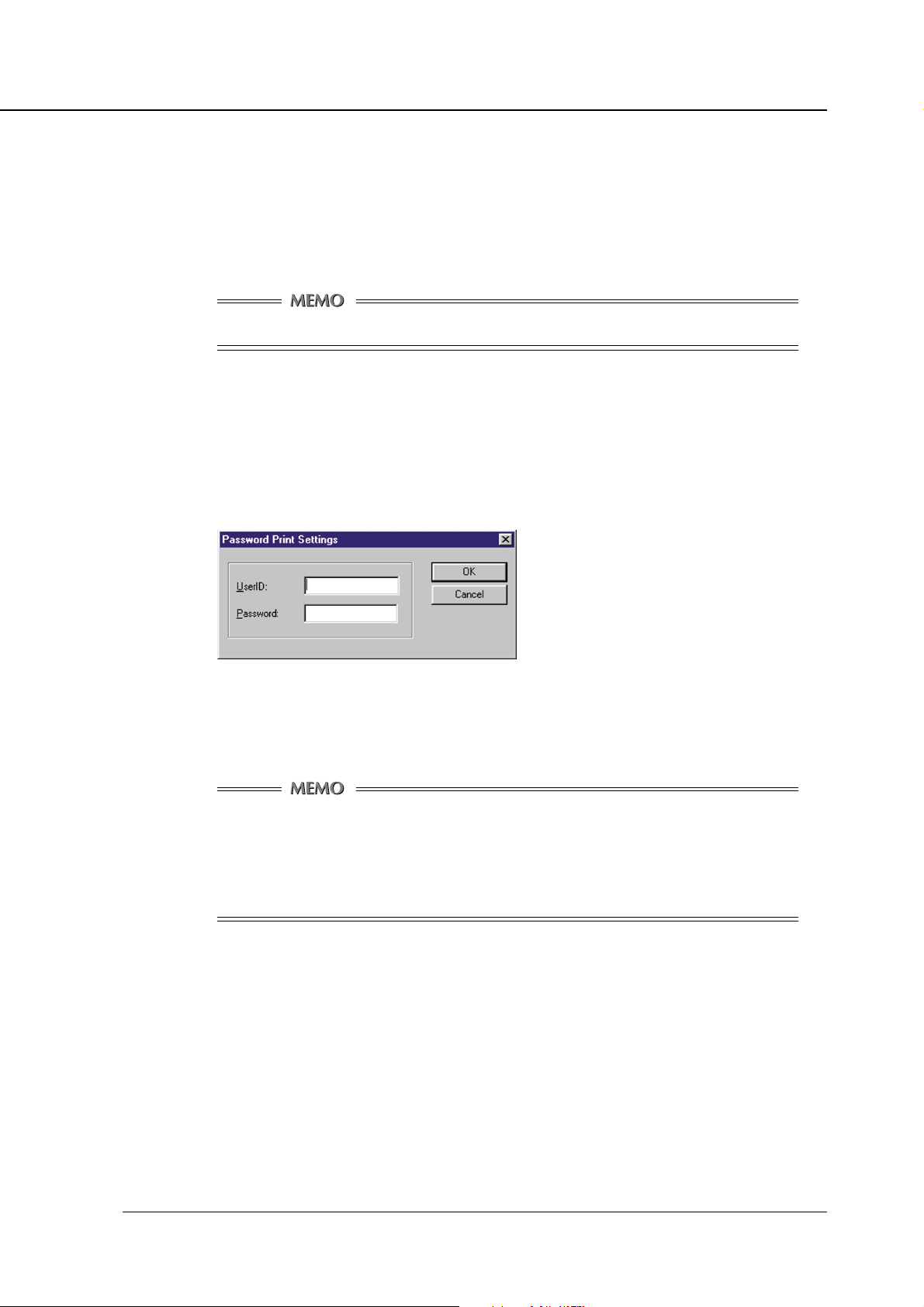
Chapter 4 Control Panel Setup
● Password Print
A Confidential Output feature enables you to password protect specific print jobs. The printing process starts only when you enter a password on the control panel of the main body printer that you set
up when transferring a print job from your computer.
With this feature you can manage confidential documents without worrying about someone else having access to them.
To use a Password Print, you need to install an optional hard disk.
Password Print Procedures
● On your computer:
1. Display the Printer Properties dialog.
2. Click the [Settings] button on the [Paper] tab.
[Password Print Settings] dialog appears.
When you have already set up the password on the [Password Print Settings] dialog, go to step 6.
3. Enter your user ID in the [UserID] text box.
You can select any 5-digit number for the user ID.
Providing the Printer EKC feature has been set on the copier, [User ID] set up in the
[Settings] dialog is recognized for a password for Printer EKC.
Provided a Printer EKC feature has been set on the copier, you can enter the same
number in the [User ID] text box as that representing your password for Printer EKC.
For Printer EKC, refer to “ Chapter 6 Printer EKC ”.
4. Enter your password in the [Password] text box.
You can select any 8-digit characters for your password.
5. Click the [OK] button.
6. Put a check in [Password Print] on the [Paper] tab.
7. Set up the other functions if necessary, then start to print.
Print Controller INSTRUCTION MANUAL 4-11
Page 65

Chapter 4 Control Panel Setup
● On the control panel:
8. Press the [PRINTER] button to display the printer mode basic screen.
Printer Mode Basic screen will appear.
9. Press the [SETTING] key to get the Printer Menu screen to appear, and then press
numeric key [5] to select [5. Password Print] and press the [OK] key.
Password Print screen will appear.
10. Enter a user ID using the numeric keys and press the [OK] key.
Password Input screen will appear.
11. Enter a password using the numeric, upper or lower case keys, and touch the [OK]
key.
A list showing relevant print jobs will appear. Or, if there is no relevant job, a corresponding message
will appear. If this is the case, press the [CANCEL] key to quit Password Print.
12. From the list, select the desired print job, and touch the [PRINT] key.
The printing process will start.
Deleting Password Print Jobs
You can delete print jobs once set for Password Print.
To do this, in the window appearing in step 12 under the heading of “Password Print Procedures”, select the print job you want to delete, and touch the [DELETE] key in the window.
Print jobs of Password Print are saved to the print controller’s hard disk. The saved data
is automatically deleted 24 hours later.
● Format HD
If you select [6. Format HD] on the Printer Menu Screen, a format confirmation screen will
appear. For details, refer to “Hard Disk-related Troubles” under the heading of Troubleshooting
in Appendix A.
4-12 Print Controller INSTRUCTION MANUAL
Page 66

■ Key Operator Settings
The key operator setting feature allows you to change the default values of PRINTER/SCANNER
settings to suit your requirements, as provided on the LCD panel of the copier.
● To enter Key Operator mode:
1. Press the COPY button to display the Copy screen.
2. Press the HELP button.
3. Press the [KEY OPERATOR MODE] key.
4. If preset, enter the key operator's exclusive password. For details, see the copier's
INSTRUCTION MANUAL.
5. Press the [OK] key.
The key operator screen will appear.
Chapter 4 Control Panel Setup
6. Press the [2. Printer/Scanner] key.
● Setting Items
[Auto reset timer]
Determines the time when the scanner screen switches to the printer screen.
Options:
30 sec., 60 sec., 90 sec., 120 sec., 150 sec., 180 sec., 210 sec., 240 sec., 270 sec.,
sec., OFF (default)
300
Print Controller INSTRUCTION MANUAL 4-13
Page 67

Chapter 4 Control Panel Setup
[Output tray]
Specifies a default output tray.
Options: Tray1 (default), Tray2, Tray3
[PRINT W/O key count]
You can set the printer working to remove the key counter while printing out.
Options : Valid, Not valid (default)
Valid : The printer operates as set on the copier.
Not valid : The printing function is available regardless of whether the key
[Scan Quality]
Allows you to select the default resolution of the scanner.
Print data is lost if no key counter is mounted.
For the current settings on the copier, contact service personnel.
counter is installed.
Options : 200dpi (default), 300dpi, 400dpi, 600dpi
[SCAN W/O key count]
You can set the scanner to remove the key counter while the scanner is functioning.
Options : Valid, Not valid (default)
Valid : The scanner operates as set on the copier.
For the current settings on the copier, contact service personnel.
Not Valid : The scanner is available regardless of whether the key counter is
installed.
[Moving to power save]
Determines the time when the power saving mode switches back on after the printing process
starts.
Options : Normal (default), Immediate.
Normal : The power saving mode switches back on at a time preset in the
power saving time setting mode.
Immediate
4-14 Print Controller INSTRUCTION MANUAL
: The power saving mode switches back on after 1-minute of printing.
Page 68

Chapter 5 Scanner
■ Brief Description of the Network Scanner ...........5-2
■ Pre-operations ..................................................... 5-3
●
Compliant OS for installing the
Konica Network Scanner Driver
● To install the Konica Network Scanner Driver ............... 5-3
: ..........................................
5-3
■ Scanning from the copier..................................... 5-4
● To scan documents .......................................................5-4
● Scanner setting screen ................................................. 5-6
■ Scanner Application Functions ............................ 5-8
● Application Functions select screen ............................. 5-8
■ Reading in Scanned Data.................................. 5-11
● Konica Network Scanner Driver's Main Screen ..........5-11
■ To import scanned data ..................................... 5-13
■ To delete scanned data...................................... 5-15
■ Setting the Konica Network Scanner Driver ...... 5-16
● To access the Change Settings screen. ...................... 5-16
● Setting Items ............................................................... 5-16
Print Controller INSTRUCTION MANUAL 5-1
Page 69

Chapter 5 Scanner
■ Brief Description of the Network Scanner
Original document images scanned into the E-RDH memory from the copier’s RADF or platen glass
are stored on the print controller's hard disk as a TIFF file. During scanning preparation, you can set
such things as enhancement, magnification, resolution, dual page copying, non-image area erasure,
etc.
To scan documents, you must first specify a 4-digit box number on the control panel. This box number
is handled like a folder on the controller's hard disk. The saved file can be read into TWAIN-capable
Windows applications through the network for editing/storage. This process also requires a box number.
Data scanned into the controller's hard disk can be cleared only from computers on the network.
Hard Disk
Original
Copier
E-RDH
Print Controller
Box No. 0124
Document No.
Document No.
Network Interface Card
Box No. 5432
TWAIN-capable Application
Network Scanner Driver
Ethernet
TCP/IP(FTP)
You have the option to let the data stored on the hard disk be automatically deleted 24
hours later, as set on the copier.
For more information on the automatic deletion of data stored on the hard disk, refer to
“ Chapter 4 Controller Set, Scan Data Auto Del ”(page 4-9).
Formatting the hard disk with [Format HD] lets you delete all data on the hard disk.
5-2 Print Controller INSTRUCTION MANUAL
Page 70

■ Pre-operations
To use the printing system as a scanner, a Konica Network Scanner Driver must be installed on the
computer in which a TWAIN scanner driver-equipped application has been previously installed.
● Compliant OS for installing the Konica Network Scanner Driver:
• Windows95/98/Me
• WindowsNT4.0
• Windows2000
For the printing system to be used as a scanner, you need the hard disk and network
interface card.
The PC and the printing system need to be connected to the network. The parallel port
is not available for scanning.
It is necessary for the PC and the network interface card to be assigned appropriate IP
addresses, and that the TCP/IP network be enabled. For the TCP/IP settings of the
network interface card, see the network interface card INSTRUCTION MANUAL.
Chapter 5 Scanner
● To install the Konica Network Scanner Driver
1. Switch on power to the PC, and start Windows.
Exit all open Windows applications.
2. Insert the User Software CD into the CD drive.
3. Double-click the My Computer icon on the desktop to open the My Computer window, and then double-click the icon corresponding to the connected CD (i.e., User
Software CD).
4. Double-click Setup.exe in the [Scanner] folder.
5. Follow the instructions given in the installation wizard screen.
Select [English] from the [Select Language] list on the Install wizard screen.
Print Controller INSTRUCTION MANUAL 5-3
Page 71

Chapter 5 Scanner
■ Scanning from the copier
Document images scanned by the copier can be stored on the print controller's hard disk as a TIFF
file. To do this, you have to specify a 4-digit box number.
● To scan documents
1. Place the document to be scanned on the copier RADF or platen glass.
2. Press the [SCANNER] button on the Control panel to switch the display to the scanner main screen.
3. Enter a 4-digit box number and press the [OK] key. The display will switch to the
scanner setting screen. Be sure to jot down your box number, as you will need it
when reading in scanned data from the PC.
When using the system as a scanner, it is recommended that box numbers be previously assigned and made known to individual users via e-mail or other means.
The box number assists in protecting the individual users’ data.
5-4 Print Controller INSTRUCTION MANUAL
Page 72

Chapter 5 Scanner
4. If the message [Position original in the RADF face-up] appears on the LCD display,
set elements such as Text/Photo Enhancement, SCAN DENSITY, SCAN MODE, Quality,
SIZE, Application Functions, etc. as required, and then scan the document as follows:
5. Press the [SCAN] key on the LCD display. The document placed on the platen glass
or RADF will be scanned with the current settings.
As the document is scanned, the scanned data is temporarily held in the copier's E-RDH memory. It
is not yet stored on the controller's hard disk. When the document is scanned through and you have
another document to scan, simply set it in place as you did for the previous one, and press the
[SCAN] key again.
Pressing the START button allows you to upload the scanned data to the controller's hard disk.
Additional documents you scan by pressing the [SCAN] key are handled together with
the first document as a series of documents (namely, they are stored as one file.).
You can press the START button instead of the [SCAN] key to let the loaded document be directly
uploaded to (stored on) the hard disk as a TIFF file when the scanning process is over.
The image direction you will have on reading application depends on the original document direction.
Original sizes you can scan and the procedure for loading originals are the same as in
the copy mode. For more on this, refer to your copier’s INSTRUCTION MANUAL.
Print Controller INSTRUCTION MANUAL 5-5
Page 73

Chapter 5 Scanner
● Scanner setting screen
Features
(1) [Box No.] key
Allows you to enter a box number.
Pressing this key gives access to the box number display screen.
(2) [SCAN] key
Lets the document scanning process start in memory mode.
The loaded document is scanned and stored in the E-RDH memory.
Pressing the [START] key allows you to upload the scanned data to the controller's hard
disk.
(3) [Text/Photo Enhance]
Allows you to select a degree of enhancement. One of 4 options is always selected. By
default, [Text/Photo] is selected.
(4) [SCAN DENSITY]
Allows you to select a scan density.
During the scanning process, you can change the scan density by page. But you cannot
select Auto in the process.
(5) [SCAN MODE]
This feature allows you to scan the documents. The default value is set in common with
the copier mode.
For the copier’s default setting (Key Operator Mode), please refer to the copier’s INSTRUCTION MANUAL.
In a machine with no RADF installed, the Duplex button is not selectable.
(6) [LENS MODE] key
Allows you to change magnification before starting the scanning process.
You cannot choose some reduction rates depending on the resolution selected.
Image data can be read into [Postcard] at minimum in paper size, or into [A3] at
maximum.
5-6 Print Controller INSTRUCTION MANUAL
Page 74
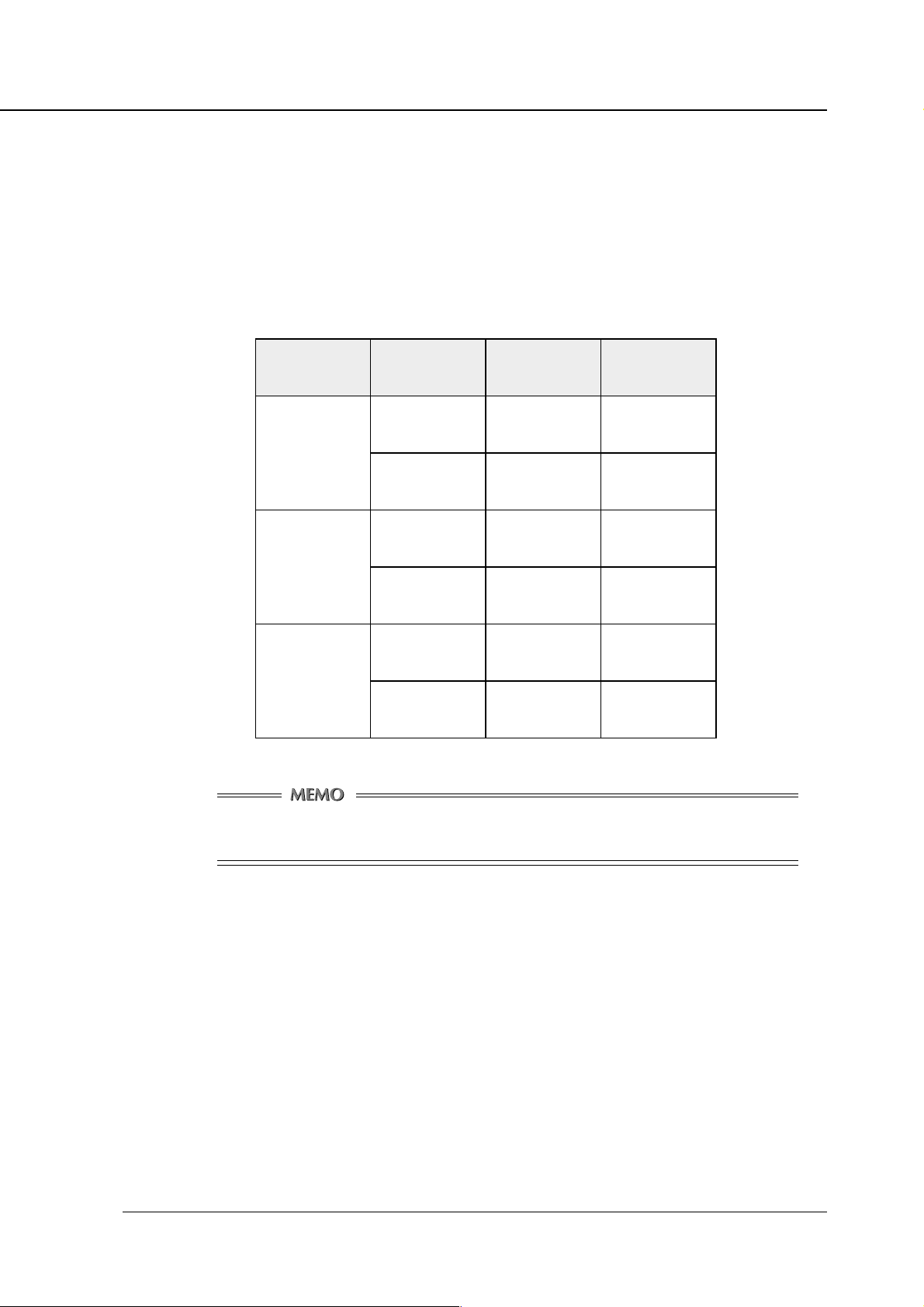
Chapter 5 Scanner
(7) [Quality] key
Allows you to select the resolution.
The default Quality setting depends on the key operator mode setting of the printer. For
the key operator mode, see “Chapter 4, Control Panel Setup”.
The scanned data is read into the copier’s memory (E-RDH). If scanned data exceeds the
E-RDH capacity, which translates into an error, you cannot go on with scanning.
The following table shows how many A4-size originals can be scanned with the copier’s
standard memory (32 MB).
noituloseR lanigirO
ipd002
ipd004
ipd006
eziSataD
)teehs1(
ylnotxeTBK07tuobA034tuobA
erutciPdnatxeTBK031tuobA032tuobA
ylnotxeTBK002tuobA051tuobA
erutciPdnatxeTBK084tuobA06tuobA
ylnotxeTBK034tuobA07tuobA
erutciPdnatxeTBM34.1tuobA02tuobA
slanigirOfo.oN
Data Size and No. of Originals available to be read depend on data actually scanned.
Understand the numbers in the table to be intended to serve as a rough guide for you.
(8) [SIZE] key
Available only when using the Platen mode.
Allows you to select a scanning frame size.
Example: When an A3-size original is loaded and you select B5-size, then scanning takes
on the B5-size frame.
Options: A3, A4R, A4, A5, 81/2 x 11R, 81/2 x 11, F4, B4, B5R, B5
Default is AUTO.
Print Controller INSTRUCTION MANUAL 5-7
Page 75
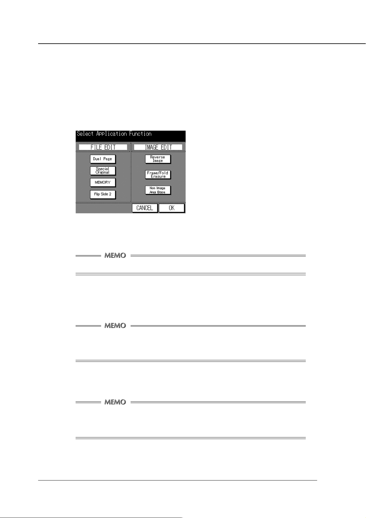
Chapter 5 Scanner
■ Scanner Application Functions
This screen allows you to set each application function such as Dual Page, Flip Side 2, and Reverse
Image in scanner mode. Pressing the [APPLICATION] button on the Scanner setting screen switches
the display to show the Application Function select screen.
● Application Functions select screen
After selecting the desired application function(s), touch the [OK] key to set the function and
restore the sanner setting screen. Or touch the [CANCEL] key to cancel the setting data and
restore the scanner setting screen.
For details of each feature, refer to the copier’s Instruction Manual.
Function of each key
[Dual Page]
Sets/Cancels the dual page direction selection.
Memory mode and Non Image Area are selected automatically (each mode is cancelable), but it cannot be used in combination with the Frame Erasure or Mixed Original
mode.
[Special Original]
Sets/cancels the Mixed Original mode and the Folded Original setting.
In Mixed Original mode, it cannot to be used in combination with the Dual Page, Fold
Erasure, Non Image Area Erase, Flip Side 2, or Folded Original modes.
In Folded Original, it cannot be used in combination with the Non Image Area Erasure.
5-8 Print Controller INSTRUCTION MANUAL
Page 76

Chapter 5 Scanner
[MEMORY]
Sets/ cancels the Memory mode.
When the memory mode is set up, you cannot upload the scanned data to the controller's
hard disk by directly pressing the START button.
[Flip Side 2]
Allows you to align the back side of the original so that the head of the page becomes the
foot of the front side when the RADF duplex mode is selected.
Top/Bottom bind Left/Right bind
1
2
3
1
2
3
3
2
1
3
2
1
This feature cannot be used in combination with Dual Page, Mixed Original or Non
Image Area Erase modes.
Print Controller INSTRUCTION MANUAL 5-9
Page 77

Chapter 5 Scanner
[Reverse Image]
This feature cannot be used in combination with the Non Image Area Erase mode.
[Frame/Fold Erasure]
The Fold Erasure mode cannot be used in combination with the Dual Page or Mixed
Original modes.
[Non Image Area Erase]
Allows you to enable/disable the reverse image mode.
Allows you to enable/disable the frame/fold erasure feature.
Allows you to enable/disable the Non Image Area Erase mode.
This feature cannot be used in combination with Mixed Original, Folded Original or
Reverse Image mode.
If lighting equipment is present just above the machine, the original size may not be
correctly identified.
5-10 Print Controller INSTRUCTION MANUAL
Page 78

■ Reading in Scanned Data
TWAIN-equipped applications are used to read in scanned data. Select a TWAIN driver from your
application (the Konica Network Scanner Driver is selected in this procedure), select a scanner (copier
having scanned original) using the TWAIN driver, then enter the box number corresponding to the
scanned data so that the scanned data can be read in from the print controller's hard disk.
There are several TWAIN-capable applications on the market. In this manual, Adobe PhotoShop LE is
used to illustrate how to read in scanned data.
● Konica Network Scanner Driver's Main Screen
Chapter 5 Scanner
Displayed Information
[Box No.]
Shows the currently selected box number.
[Scanner Name]
Shows the currently selected scanner's name. Any desired name can be entered.
[Document]
Shows scanned data file numbers. Numbers are automatically assigned in sequence.
[Date & Time]
Shows the date and time each scanned data file was generated.
[Page]
Shows the total number of pages of each scanned data file.
[Size]
Shows the horizontal and vertical pixel numbers of the first page of each scanned data file.
[Resolution]
Shows horizontal resolution (dpi) of the first page of each scanned data file.
Print Controller INSTRUCTION MANUAL 5-11
Page 79
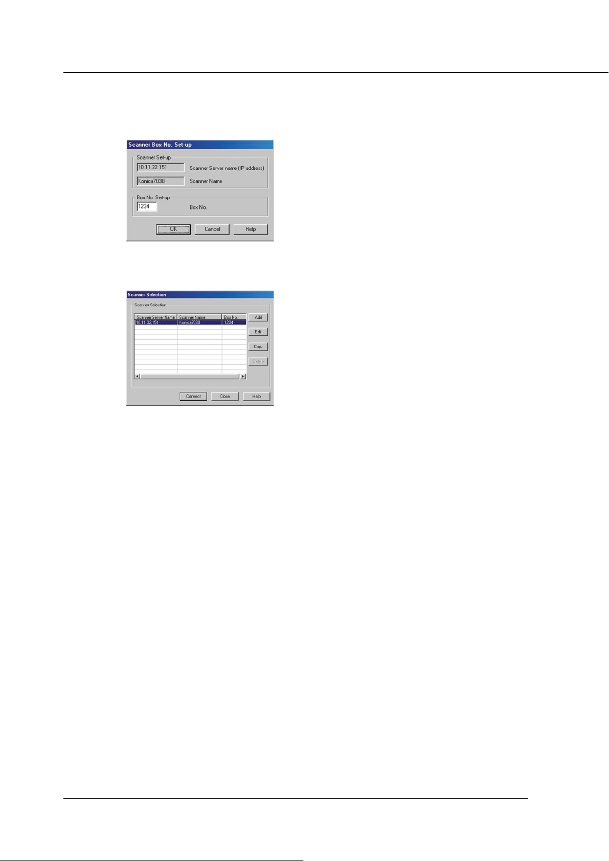
Chapter 5 Scanner
Functions
[Box No. Selection] key
Click this key when changing only the box number of the currently connected scanner.
[Scanner Selection] key
Click this key when establishing connection to an another scanner, registering new scanner
settings, performing editing, copy and delete.
[Page Selection] key
This key is used to select a page or pages when reading in a scanned data file. By default, "All"
is selected. With applications that cannot handle files containing multiple pages, "Specify page"
is set to "1."
If you select “Specify page”, selected pages are limited depending on the total number of pages
scanned by the copier.
[Reading] key
This reads in a selected scanned data file from the scanner.
[Delete] key
This deletes a selected scanned data file.
[Refresh] key
This updates information in a scanned data file in the selected box number field, so it reflects all
changes you made most recently.
[Option] key
This is used to change various settings of the scanner driver.
[Close] key
This key is used to close the scanner driver.
[Help] key
This key is used to access Help.
5-12 Print Controller INSTRUCTION MANUAL
Page 80

■ To import scanned data
1. Run the Application that conforms to TWAIN (Adobe PhotoShop LE).
2. Select File - Acquire, and select [Select TWAIN_32_Source...].
3. Select [Konica Network Scanner Driver] in the Select Source dialog box.
4. Click the [Select] button.
5. Select File - Acquire [TWAIN_32_Source...].
Chapter 5 Scanner
6. In the Scanner Box No. Set-up dialog box, enter the server name (IP address) of the
scanner you want to connect to, the scanner name the driver to identify the scanner,
and the box number you entered when scanning the document. Then click [OK].
Once the Scanner setting has been set, this dialog box is not displayed the next time you perform a
scanning task. To display this dialog and use another scanner, click [Scanner Selection] button on the
Konica Network Scanner Driver’s Main Screen. Then click [Add] button on the Scanner Box No. Set-
up dialog box.
Neither the DNS nor the NetBIOS names can be used as a Scanner Server name.
Print Controller INSTRUCTION MANUAL 5-13
Page 81
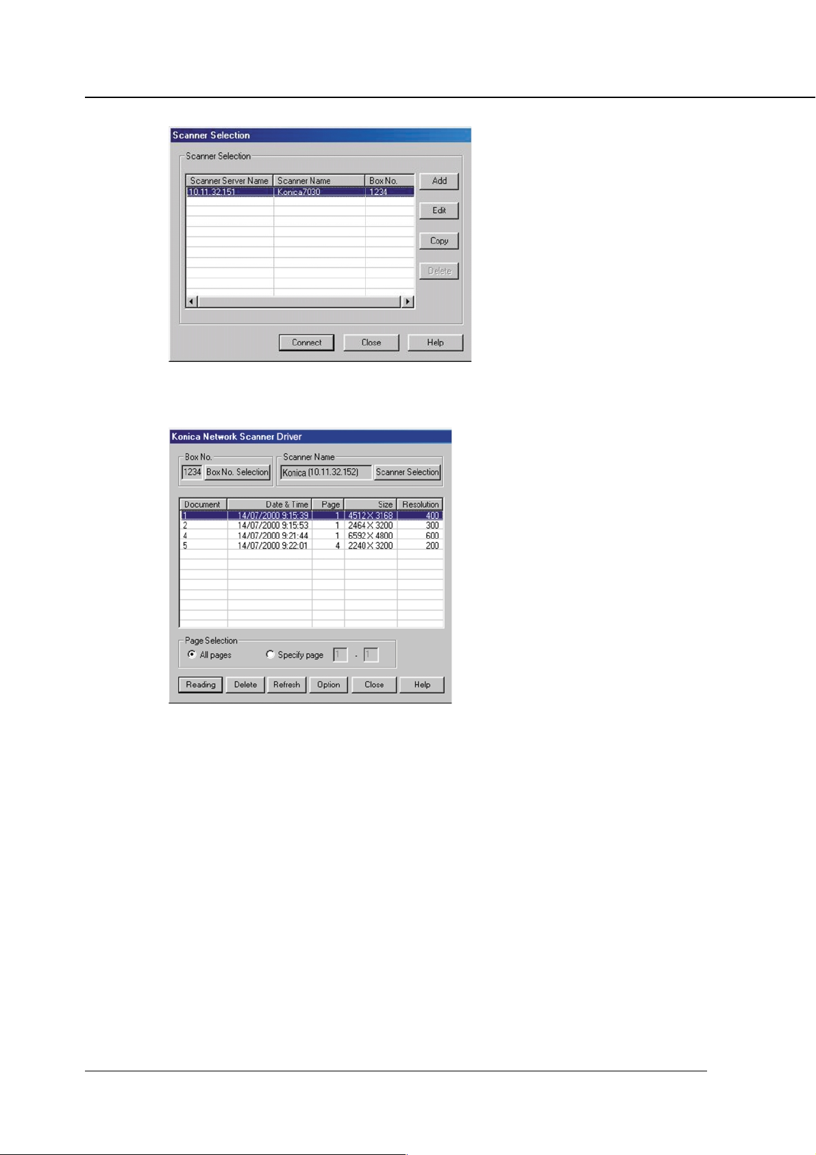
Chapter 5 Scanner
7. After selecting a scanner, click [Connection] .
The Konica Network Scanner Driver main window will appear.
8. Select a file from the file list shown in the main window, then click [Reading] to allow
the selected file to be read in. By default, the file is cleared from the controller's hard
disk immediately after the file is fully read in. If you want, you can override this
default setting so that the file is held in the hard disk. To learn how to do this, see
“Setting the Konica Network Scanner Driver”.
9. You can open the read-in document within the application for editing/saving.
5-14 Print Controller INSTRUCTION MANUAL
Page 82

■ To delete scanned data
Perform the following steps to delete a scanned data file from the hard disk.
1. Run Adobe PhotoShop LE.
2. Select File - Acquire, then select [Select TWAIN_32_Source...].
3. In the Select Source dialog box, select [Konica Network Scanner Driver].
4. Select File - Acquire, then select [TWAIN_32_Source...].
5. Click [Scanner Selection].
6. Click and select an available scanner from the displayed scan job list.
7. Click [Connection].
The Konica Network Scanner Driver main window will appear.
Chapter 5 Scanner
8. From the file list shown in the main window, select a file you want to delete, and then
click the [Delete] button.
Print Controller INSTRUCTION MANUAL 5-15
Page 83

Chapter 5 Scanner
■ Setting the Konica Network Scanner Driver
You can set up the various elements of the scanner driver described below.
● To access the Change Settings screen.
1. In the Konica Network Scanner Driver main window, click [Option] to display the
Variable Option dialog box.
● Setting Items
[Use reverse display of Scanned document]
Reverse the image of the scanned document.
[Delete after Scanning in the document]
Delete a scanned document file that is temporarily held in the scanner.
[Set-up temp folder for Scanner]
This allows you to select a directory into which temporarily stored data can be read into your
application before saving it to the PC's hard disk. Click Folder Change, then specify where you
want to temporarily store the current scanned document.
5-16 Print Controller INSTRUCTION MANUAL
Page 84

Chapter 6 Printer EKC
■ Overview of the Printer EKC............................... 6-2
● Setting of Printer EKC................................................... 6-2
● Printing with Printer EKC ..............................................6-2
● Loading EKC Counter’s Value into PC .......................... 6-2
● EKC Limit ...................................................................... 6-3
Print Controller INSTRUCTION MANUAL 6-1
Page 85

Chapter 6 Printer EKC
■ Overview of the Printer EKC
Printer EKC is a feature use to manage the number of prints on the copier.
Setting the Printer EKC feature means that, provided you enter a password previously established on
the printer to request a print job, the copier counts up printouts based on the EKC counter to know
when a preset limit is hit, and also rejects a print request from a client having no valid password.
● Setting of Printer EKC
A password for Printer EKC and its counter are set in the copier’s key operator settings. For guidance
in setting Printer EKC, refer to the copier INSTRUCTION MANUAL.
A password for Printer EKC has need to be the same as User ID to enter at printing out
time.
● Printing with Printer EKC
If Printer EKC has been set as appropriate, perform the following steps to get an output.
1. Select the [Paper] tab in the printer driver properties window, and click the [Settings]
key.
[Password Print Settings] dialog will appear.
2. Type in the user ID set up in Printer EKC into the User ID text box.
You must enter the same password (5 digits or less) in the User ID text box that you set
up on the copier for Printer EKC.
If you do not enter the correct password or if you leave the User ID text box blank, the
print job is not performed and is registered as Unsuccessful jobs. When in doubt about
the password for Printer EKC, ask your system administrator.
3. Click [OK] to close the Properties and start the printing process.
● Loading EKC Counter’s Value into PC
By using a software named Konica VISUALCOUNT-MASTER, the Printer EKC feature allows you to
upload the EKC counter’s value from the copier to the print controller to load into your computer.
For how to load the EKC counter’s value into a computer, refer to the INSTRUCTION MANUAL for
Konica VISUALCOUNT-MASTER.
For details on Konica VISUALCOUNT-MASTER, contact your service representative.
6-2 Print Controller INSTRUCTION MANUAL
Page 86

Chapter 6 Printer EKC
● EKC Limit
If you try to exceed the limit previously set in Printer EKC, the following will occur depending on the
settings of Printer EKC.
When in doubt about the Printer EKC settings, ask your system administrator.
When a print job is transmitted after reaching a limit:
• A message will appear indicating that the EKC counter reached a preset limit, but the printing
process is brought about normally and the EKC counter increments as if nothing happened.
• No output is produced and the job is registered on the Unsuccessful jobs list.
If the EKC counter hits a preset limit in the process of getting an output:
• A message will appear indicating that the EKC counter reached a preset limit, but the printing
process is brought about normally and the EKC counter increments as if nothing happened.
• After the current print job is completed, no additional jobs are accepted. If you try to transmit
the next print job, it is deleted and registered on the Unsuccessful jobs list.
• The print job instantly stops, causing the already fed paper to be output. The job is registered
on the Unsuccessful jobs list.
A print job deleted by the Printer EKC feature is registered on the Unsuccessful jobs list.
For information on checking the Unsuccessful jobs list screen, refer to “ Appendix A
Troubleshooting ”.
Print Controller INSTRUCTION MANUAL 6-3
Page 87

Appendix A Trouble Shooting
■ Basic Troubleshooting......................... Appendix A-2
■ General Problems of Printing ............. Appendix A-2
● The Print Controller does not respond
to the “Print” command .......................... Appendix A-2
● A message prompts you load to a
paper size not currently loaded ............. Appendix A-2
● You cannot print the test print ....................... Appendix A-3
● The print setting of a job does not correspond
to the printing result ............................... Appendix A-3
● [Duplex] is not selectable ............................. Appendix A-3
■ Troubles Concerning the Scanner ...... Appendix A-4
● Cannot connect to the scanner .................... Appendix A-4
■ Hard Disk-related Errors ..................... Appendix A-4
● The hard disk does not work correctly ......... Appendix A-4
■ Checking on Unsuccessful jobs.......... Appendix A-5
Print Controller INSTRUCTION MANUAL Appendix A-1
Page 88

Appendix A Troubleshooting
■ Basic Troubleshooting
This section describes how to troubleshoot ordinary problems that may occur. If a problem cannot be
remedied by using the following countermeasures, contact your service representative.
Refer to these basic countermeasures before looking into specific solutions.
1. Check the power and cable connections of the copier and computers.
2. Check the LCD of the copier for information concerning the current problem.
3. If possible, print the “Test Print” to check that the settings are appropriate.
4. Check the current status of the Print Controller.
Check the current status shown on the LCD of the Copier Control Panel.
When your job is being processed or waiting to be printed, the current status may be displayed in a
dialog box by double-clicking [Start]-[Settings]-[Printers]-[Konica IP-431 PCL].
5. Turn off the main power of the copier, and switch it back on 10 seconds or more later.
• If the optional hard disk is not connected and data are transmitted both via parallel port and
network simultaneously, the print controller may not work correctly.
■ General Problems of Printing
● The Print Controller does not respond to the “Print” command.
1. Check that [Konica IP-431 PCL] is selected as the current printer.
[Konica IP-431 PCL] must be selected as the current printer in Windows before printing.
2. Check that the power switch of the copier is turned on.
3. Print the “Test Print”.
When you cannot print a job from a computer even though you can print a test print, contact your
system administrator or service provider.
● A message prompts you load to a paper size not currently loaded.
1. Cancel the job and change the paper size in the “Page (Paper) Setup” dialog box of
the application.
Appendix A-2 Print Controller INSTRUCTION MANUAL
Page 89

Appendix A Troubleshooting
● You cannot print the test print
1. Check the LCD of the copier Control Panel.
When “Ready to copy” is displayed on the LCD, go to Step 3.
When a diagnostic message or an error message is displayed on the LCD, refer to the copier IN-
STRUCTION MANUAL.
When the LCD is blank, go to Step 2.
2. Press the sub power sw on the Control Panel.
When the copier is used in the Power Save mode, press this switch to show the LCD in the Display
mode.
3. Try to make a copy.
When copy is available, go to Step 4.
4. Turn off the copier and restart it. Print the test print again when the Print Controller
is ready.
If you cannot print the test print after taking the measures shown above, contact a service represen-
tative.
● The print setting of a job does not correspond to the printing result.
1. Confirm that the printer setting has not been changed.
Refer to “Chapter 3 Printer Driver Printer Driver Function List” for the printer setting (page 3-7 ).
● [Duplex] is not selectable
1. Press the [Restore] button to switch the [Setup] and [Paper] tabs back to their default
status.
2. Make sure that options other than [B6] is selected as Paper Size.
3. Make sure that [Plain paper] is selected as Media Type.
4. Make sure that Booklet is switched OFF.
Print Controller INSTRUCTION MANUAL Appendix A-3
Page 90

Appendix A Troubleshooting
■ Troubles Concerning the Scanner
● Cannot connect to the scanner
When an error dialog appears when attempting to access the scanner, perform the following checks:
1. Check whether the correct IP address of the scanner has been entered.
If the entered IP address is not correct, enter the correct one.
If the entered IP address is correct, go on to step 2.
2. From the DOS prompt run a ping test through the destination host to the IP address
of the scanner.
If the ping test fails, check whether the copier’s main power is switched on, and also check the
network cable for proper connection.
If the ping test is successful, go on to step 3.
3. Check whether the IP router is correctly set.
If it is not correctly set, set it correctly.
If there is no problem in IP router setup, go on to step 4.
4. Trace the routing to the scanner to check whether there are any error conditions
within the network.
If any error conditions are found, eliminate them.
If no error is found and yet the connection to the scanner cannot be established, contact your service
representative.
■ Hard Disk-related Errors
● The hard disk does not work correctly
If the main power switch is turned off while the hard disk is running, the hard disk may not work
correctly and the data is busy written into it. To fix the hard disk, you need to format it as follows.
1. Switch on power to the copier and display the Printer Menu Screen.
2. Select [6. Format HD] on the Printer Menu Screen and press [OK].
3. Select [1. Yes] on the format start screen displayed.
4. You may get the message [Please turn off/on], then turn off the main power of the
copier and 10 seconds or more later turn it back on.
If this procedure does not solve the problem, contact your service representative for details.
Appendix A-4 Print Controller INSTRUCTION MANUAL
Page 91

■ Checking on Unsuccessful jobs
If print jobs are not output, you can check them on the Unsuccessful jobs list screen.
To get the No complete Job List screen to appear:
1. Press the [JOBLIST] key on the printer mode base screen to get the Job List screen
to appear, and then press the [Unsuccessful jobs] key.
The Unsuccessful jobs list screen will appear.
You can scroll the list up/down with the [
Content of Unsuccessful jobs list
On the Unsuccessful jobs list you can check on the mode, file and application names, as well as
the causes of Unsuccessful jobs.
Here is a list of No complete Job List content.
edoM rotcaF sesuacfonoitpircseD
Appendix A Troubleshooting
/ ] keys.
lecnaC
reffiDDI .hctamtondidDIresUesuacebtuptuotonboJ
RETNIRP
revotimiL .timilteserpadehcaerCKEretnirPesuacebtuptuotonboJ
lluFmeM .yromemfotuonarreipocesuacebtuptuotonboJ
lluFDH .ksiddrahotatadgnidaolpunidetelpmoctonboJ
RENNACS
lecnaC
.yromemnirorrE.noitanimaxeLerofebdetibihorpypoC.tnuoc
.detrobaboJ.rellortnoctnirpmorftseuqernoitpurretnI
You can return to the Joblist screen from the Unsuccessful jobs list screen by pressing
the [PRINT JOB] key.
When switching the copier’s main power OFF, Unsuccessful jobs in the Unsuccessful
jobs list screen are deleted.
.tes/tnuocyekO/W.tsilboJmorfdeteleD.RAELC/POTShtiwdeppotS
beWybdetibihorP.detrobaboJ.rellortnoctnirpmorftseuqernoitpurretnI
.tes/tnuocyekO/W.tsiLboJmorfdeteleD.RAELC/POTShtiwdeppotS
Print Controller INSTRUCTION MANUAL Appendix A-5
Page 92

Appendix B Product Specifications
■ Product Specifications ........................ Appendix B-2
Print Controller INSTRUCTION MANUAL Appendix A-1
Page 93

Appendix B Product Specifications
■ Product Specifications
Model: IP-431 Print Controller
Paper size: You can select from the following paper sizes:
Built into the Konica 7045 Copier
detcelesebotezisrepaP
5.5" 5.8x"
11x"5.8"
"41x"5.8
"71x"11
mm024x792-3A
mm792x012-4A
mm012x841-5A
mm453x052-4B
mm752x281-5B
mm281x821-6B
sehcni31x0.8-4F
mm093x762-K8
mm762x591-K61
Paper type / Capacity: Same as copier
Paper Feeding and Amount
of Feeding Paper: Same as copier
Load Output Paper: Same as copier
Mode: Dual operation Copier and Printer is available.
(Up to 5 jobs, including scanning jobs, can be processed at
a time.)
Special Printing: Offset, Staple, Combination, Front / Back cover insertion, Du-
plex, Overlay, Password Print, etc.
Orientation: Portrait and Landscape.
Resolution: Printer Resolution: 600 dpi
Scan Resolution: 200 dpi/300 dpi/400 dpi/600 dpi
Gradation: 1 bit
No. of Print: 1 to 999
Printable Area: Head Margin: 4 mm, Foot Margin: 4 mm and
Right and Left Margins: 4 mm (Depends on application)
Warm-up: Same as copier
Appendix B-2 Print Controller INSTRUCTION MANUAL
Page 94

Appendix B Product Specifications
Basic Configuration
Control Board
CPU: Pentium MMX-266MHz
Program Memory: FLASH ROM (Compact Flash)
System Memory: 32 MB SD-RAM (Standard),
Expandable up to 160 MB (Option:MU-403/MU-404/MU-405)
Interface: Parallel port
Centronics (IEEE 1284) / amphenol 36 pin male connector
Network Interface (Option):
KN303: Ethernet (100Base-TX / 10Base-T)
Protocol: IPX/SPX (NetWare)
TCP/IP (LPD/LPR, Peer to Peer)
Compliant OS: Windows 95/98/Me
Windows NT4.0/2000
Printer Language: PCL 5e
Printer Driver: Printer Driver for Windows 95/98/Me, Windows NT4.0/2000
Compliant Host Computer: A Windows-based computer
Compliant Finisher: FS-109
Compliant DB: DB-208, DB-208A, DB-608
Dimension: 260 mm (W) x 190 mm (D) x 55 mm (H)(Not including FAN)
10.3 inches (W) x 7.5 inches (D) x 2.2 inches (H)
(Not including FAN)
85 mm (H)(Including FAN)
3.4 inches (H)(Including FAN)
Weight: Approx. 1.2 kg (2.6 pounds)
Power: Supplied from the main body
Working Environment: Temperature: 10 degree °C to 30 degree °C
50 degree °F to 86 degree °F
Humidity: 20 % to 80 %RH (non-condensing)
Restrictive Conditions
• Although the copier’s Weekly Timer function is available in the Printer mode, power does
not turn Off when print data remains in the E-RDH until the data output is finished.
• If the optional hard disk is not connected and data are transmitted both via parallel port and
network simultaneously, the print controller may not work correctly.
Notice: Specifications are approximate and subject to change without notice.
Print Controller INSTRUCTION MANUAL Appendix B-3
Page 95

Appendix C Font List
■Internal Font List .................................. Appendix C-2
Print Controller INSTRUCTION MANUAL Appendix C-1
Page 96

Appendix C Font List
■ Internal Font List
Internal Fonts list
IP-series Printer
Appendix C-2 Print Controller INSTRUCTION MANUAL
Page 97

Appendix C Font List
Print Controller INSTRUCTION MANUAL Appendix C-3
Page 98

INDEX
INDEX
A
[About] tab ................................................ 3-21
Add Port ................................................... 3-10
B
Back Cover............................................... 3-18
C
Collate ...................................................... 3-12
Color......................................................... 3-21
Combination ............................................. 3-17
Compact Flash ........................... Appendix B-3
Compliant OS ..................................... 1-8, 3-3
Contents of Settings ................................... 2-8
Control Panel ............................................. 4-3
D
Data Flow ................................................... 1-5
[Details] tab .............................................. 3-10
Duplex ...................................................... 3-14
M
Memory .............................................. 1-4, 1-6
O
OHP ......................................................... 3-13
[Options] tab ............................................. 3-19
[Overlay] tab ............................................. 3-20
P
Pages per sheet ....................................... 3-19
Paper size ................................................ 3-13
[Paper] tab................................................ 3-13
Parallel Port ................................................. viii
Password Print ......................................... 4-11
Print from Applications ............................... 2-7
Print Jobs ................................................... 4-6
Printer Driver Function List......................... 3-7
Printer EKC ................................................ 6-2
Printer Menu Screen .................................. 4-5
Printer Mode Basic Screen ........................ 4-4
Printer Setting Menu .................................. 4-7
Property of Printer Driver ........................... 3-3
Protocol ...................................... Appendix B-3
E
E-RDH ........................................................ 1-3
F
Font List ..................................... Appendix C-2
Front Cover .............................................. 3-17
G
[General] tab ............................................ 3-10
[Graphics] tab ........................................... 3-18
H
Hardware Configuration ............................. 1-4
I
Installation of the Printer Driver .................. 2-3
Introduction .................................................... v
I/O Interface ............................................... 1-4
K
S
Scanner ...................................................... 5-2
Scanner Application Functions................... 5-8
Scanner setting .......................................... 5-6
Scanning from the copier ........................... 5-4
Select Bitmap ........................................... 3-20
Set Default ....................................... 4-5, 4-19
[Setup] tab ................................................ 3-21
[Sharing] tab ............................................. 3-12
Specifications ............................. Appendix B-2
Staple ....................................................... 3-15
System Requirements ................................. viii
T
Test Page ................................................... 2-6
Test Print .................................... Appendix A-3
Test Print Menu .................................. 4-5, 4-8
Troubleshooting .......................... Appendix A-2
Key Operator mode .................................. 4-13
LCD Panel .................................................. 4-4
Index-1
Page 99

MANUFACTURER
●
KONICA CORPORATION
●
TOKYO JAPAN
2001. 4
IP431_INT_v111
 Loading...