

Page 1
SERVICE MANUAL
DYNAX 5D
MAXXUM 5D
SWEET DIGITAL
5 DIGITAL
COMMON MODEL:
DYNAX 5D PEU/PHK/PAS/PAU/Mid-East-India/
MAXXUM 5D PUSA/ PCA/South-America/Taiwan (2186-300)
SWEET DIGITAL (Black) PJ (2186-600)
SWEET DIGITAL (Silver) PJ (2186-650)
5 DIGITAL PMSH-SKD model (2186-090)
Korea/Iran-Sylia (2186-100)
TECHNICAL ILLUSTRATION
PARTS NOTICE WITH PARTS LIST
TECHNICAL REPAIR MANUAL
KONICA MINOLTA PHOTO IMAGING, INC.
Page 2
2186 Service Manual Index
Code
QS FA9220-2186-01
Page
1
Division Camera CS Division
Completed September 30, 2005
Section/
TTL number of pages
1 Service Manual Index 1
2 Specifications 1
3
Parts List Index 3
4
Parts List 12
5
Repair Guide 62
6
Trouble-Shooting Chart
7
Check List 8
9
Revision History
Date of issue/Version Reason (Revision part)
26/08/2005 First issued
Approved by Verified by Written by
Yata Ueno
Approved by Verified by Written
Yata
by
Masuda
Ueno
13/09/2005
30/09/2005
Error correction
(pg. 21,35,40,43,44,45,56,62 Repair Guide)
Error correction (pg. 12 Parts List)
LCD HARNESS (0442)
(RED and BLUE reverse-putt ing)
Yata
Yata
Masuda
Ueno
Ueno
KONICA MINOLTA PHOTO IMAGING, INC.
Page 3

Specifications
(2186) 1
Type
Camera block
Recording
block
Viewfinder
LCD/Indication
Focus
Exposure
Flash
Recording
Playback
Others
Power/Battery
Input/Output
Dimensions
Weight
Type
Number of effective pixels
CCD
Unit cell size
Recording media
File format
Number of recorded pixels
Image quality modes
Viewfinder type
LCD monitor
Autofocus system
Autofocus area
Exposure mode
Metering
Exposure compensation
Camera sensitivity
Shutter
Shutter speed range
Flash metering
Guide number
Flash compensation
White balance control
Continuous advance
Color modes / Color space
Image correction
Playback functions
Printing output control
Battery
Battery performance (still)
PC interface
AV output
Dimensions (WxHxD)
Weight
Interchangeable-lens digital SLR camera
Approx. 6.1 million (3016x2008)
23.5mm x 15.7mm (APS-C size equivalent)
Interline primary-color, interlace scan
Total pixels: 6.3 million
7.8μm x 7.8μm
TypeⅠand TypeⅡCompactFlash cards, Microdrive,
SD memory card/ MultiMedia Card (with SD-CF1 in use)
JPEG/ RAW/ RAW+JPEG
[DCF 2.0 compliant, DPOF (supported by printing functions in ver. 1.1), Exif 2.21]
L: 3008x2000, M: 2256x1496, S: 1504x1000
Standard, Fine, Extra-Fine, RAW, Raw+JPEG (Fine)
Eye-level fixed pentaprism (Roof mirror type pentaprism (silver evaporated))
2.5 inch low-temperature polysilicon TFT color, back light LCD (with 3 fluoresent lamps)
Total pixels: 115,000 (approx.)
TTL phase-detection system with CCD line sensors
(9 points 8 lines with center cross-hair sensor)
Wide focus area, Any local focus area is selectable from 9 points sensors
P/ Auto mode (Programmed AE with program shift),
A (Aperture priority), S (Shutter priority), M (Manual)
TTL Metering using 14 segment. Honeycomb-pattern SPC.
(14 segments Honeycomb-pattern/ Center-weighted, Spot metering)
+/-2 Ev in 1/3 increments
Auto and 100, 200, 400, 800, 1600 and 3200 ISO equivalents.
Electronically-controlled, vertical-traverse, focal-plane shutter
30s - 1/4000s, Bulb
Flash sync.: 1/160s (Anti-shake OFF), 1/125 (Anti-shake ON)
ADI, Pre-flash TTL, Manual flash control
12 (in meters at ISO 100)
+/-2 Ev in 1/3 increments
Automatic, Preset (Daylight, Shade, Cloudy, Flash, Tungsten, Fluorescent),
Custom, Color temparature (Color temparature: 2500 to 9900K, CC Filter: 19 levels (M9 to G9)
Approx. 3 fps, Maximum 5 frames (RAW) (Maximum 3 frames (RAW+JPEG))
sRGB, Adobe RGB, Adobe RGB (ICC)
Color mode/ DEC (Digital Effect Control) function (*1): 10 modes (Natural Color,
Natural Plus, Portrait, Landscape, Sunset, Night view, Night portrait, B/W,
AdobeRGB, AdobeRGB (ICC)).
The contrast, color saturation, sharpness are also manually adjustable in +/- 2 steps. (*2) (*3)
*1: With this function, color space and settings of image processing such as contrast,
saturation, sharpness, white balance and a like will be controlled automatically.
*2: When B/W is selected in color mode, optional setting of color saturation is disabled.
*3: When Zone matching is selected, optional setting of contrast disabled.
Single-frame (Image only, Image and various statuses,
Image and various statuses and Histogram), Index (Selectable from 4/9/16 frames),
Enlarged playback (Up to approx 5x), Luminance limit display, File browser,
Slideshow, Auto Rotation playback (ON/OFF selectable)
Exif Print, Print Image Matching III, PictBridge
One NP-400 lithium-ion battery
Approx. number of recorded image: 400 frames. (Conforming to CIPA standard
test method with a compact flash card and NP-400 lithium-ion battery)
*1 CIPA: Camera & Imaging Products Association
USB (Full-speed 12Mbps data transfer available with USB 2.0 compatible computer)
NTSC/PAL (selectable on the camera)
130.5 (W) x 92.5 (H) x 66.5 (D) mm
575g (approx.) without batteries or recording media
Page 4

INDEX
INDEX
INDEXINDEX
(2186) 1
2186-0110
2186-0121
2186-0122
2186-0131
2186-0134
2186-0135
2186-0141
2077-0145
2186-0146
2186-0150
2186-0154
2186-0155
2186-0166
2186-0174
2186-0180
2186-0210
......
......
......
......
......
......
......
......
......
......
......
......
......
......
......
......
11 2186-0521
11 2186-0526
11 2186-0580
9, 10 2186-0584
1 2186-0721
9, 10 2186-0901
3 2186-1130
10 2186-1001
10 2186-1002
7 2186-1003
8 2186-1004
8 2186-1005
9 2186-1012
1 2186-1013
7 2186-1021
4 2186-1040
......
......
......
......
......
......
......
......
......
......
......
......
......
......
......
6 2186-1116
6 2186-1119
5 2186-1120
5 2186-1126
4 2186-1127
4 2186-1128
2 2186-1131
8 2186-1132
3 2186-1133
2 2186-1143
3 2186-1144
2 2186-1145
2 2186-1146
2 2186-1151
8 2186-1153
.....
.....
.....
.....
.....
.....
.....
.....
.....
.....
.....
.....
.....
.....
.....
.....
11
11
10
11
11
11
11
1
1
1
1
PARTS LIST
1
3
3
8
8
2186-0254
2186-0265
2186-0271
2186-0402
2186-0406
2186-0407
2186-0408
2186-0410
2186-0412
2186-0414
2186-0420
2186-0427
2186-0441
2186-0442
2186-0473
2186-0500
......
......
......
......
......
......
......
......
......
......
......
......
......
......
......
......
6 2186-1041
5 2186-1042
4 2186-1043
2 2186-1065
2 2186-1066
10 2186-1071
1 2186-1072
2 2186-1073
4 2186-1076
8 2186-1078
8 2186-1079
8 2186-1081
2 2186-1082
1 2186-1083
8 2186-1086
5, 6, 7 2186-1087
......
......
......
......
......
......
......
......
......
......
......
......
......
......
......
......
8 2186-1156
8 2186-1159
1 2186-1171
8 2186-1172
3 2186-1173
8 2186-1175
8 2186-1176
8 2186-1301
1 2186-1302
2 2186-1303
1 2186-1304
8 2181-1305
8 2186-1305
8 2186-1307
8 2181-1311
8 2186-1317
.....
.....
.....
.....
.....
.....
.....
.....
.....
.....
.....
.....
.....
.....
.....
.....
8
8
4
2
2
2
2
1
1
1
1
9
1
1
1
9
2186-0503
2186-0506
2186-0514
2186-0515
......
......
......
......
5 2186-1088
5 2186-1106
7 2186-1107
7 2186-1115
......
......
......
......
8 2186-1318
11 2186-1320
11 2186-1321
11 2186-1322
.....
.....
.....
.....
9
10
10
10
Page 5

2 (2186)
INDEX
INDEX
INDEXINDEX
2186-1327
2186-1328
2186-1329
2186-1330
2186-1331
2186-1332
2186-1333
2186-1334
2186-1335
2186-1336
PARTS LIST
2186-1401
2186-1402
2186-1403
2186-1404
2186-1407
2186-1410
......
10 2186-1444
...... 10
......
......
......
......
......
......
......
......
......
......
......
......
......
......
11 2186-1446
11 2186-1476
2186-1445
9 2186-1469
9 2186-1470
9 2186-1471
9 2186-1473
9 2186-1474
9 2186-1475
9 2162-1477
9 2186-1477
9 2186-1479
9 2186-1481
9 2166-1485
9 2186-1511
......
..... 11
......
......
......
......
......
......
......
......
......
......
......
......
......
......
11 2186-1610
2186-1611
11 2186-1612
9 2186-1613
9 2186-1614
9 2089-1620
9 2089-1621
9 2186-1625
9 2186-1812
10 2186-1813
9
9 2186-2512
9 2186-2530
9 2186-2532
11 2186-2533
6 2186-2534
.....
.....
.....
.....
.....
.....
.....
.....
.....
.....
.....
.....
.....
.....
.....
9
9
10
9
10
9
9
10
7
6
6
6
6
6
6
2186-1417
2186-1418
2181-1419
2186-1420
2186-1421
2186-1422
2186-1424
2186-1425
2186-1426
2186-1427
2186-1430
2186-1431
2186-1432
2186-1433
2186-1435
2186-1436
......
......
......
......
......
......
......
......
......
......
......
......
......
......
......
......
11 2181-1515
11 2186-1520
11 2163-1521
11 2186-1521
10 2186-1522
10 2186-1523
9 2186-1524
10 2186-1525
10 2186-1542
10 2186-1543
11 2162-1544
11 2186-1545
11 2162-1547
11 2186-1548
11 2186-1601
11 2186-1602
......
......
......
......
......
......
......
......
......
......
......
......
......
......
......
......
6 2186-2535
6 2162-2658
6 2162-2659
6 2181-2702
6 2186-2703
6 2181-2706
6 2186-2708
6 2186-2709
7 2186-2715
7 2186-2721
7 2186-2722
6 2181-2918
6 2181-2920
7 2186-2940
9 2186-2961
9
.....
.....
.....
.....
.....
.....
.....
.....
.....
.....
.....
.....
.....
.....
.....
6
5
5
4
4
4
2
2
4
4
4
4
4
2, 11
4
2186-1440
2186-1441
2186-1442
2186-1443
......
......
......
......
10 2186-1603
10 2089-1607
10 2186-1608
10 2186-1609
......
......
......
......
9 2186-4033
9 2186-4401
9 2186-4402
9 2186-4403
.....
.....
.....
.....
3
12
12
12
Page 6

INDEX
INDEX
INDEXINDEX
(2186) 3
2186-4404
2186-4508
2186-4511
2186-4514
2186-4520
2181-5016
2186-5022
2186-5025
2186-5026
2186-5027
2186-5028
2186-5033
2186-5034
2186-5041
2098-5045
......
......
......
......
......
......
......
......
......
......
......
......
......
......
......
12 9391-0807-02
8 9391-0807-03
11 9391-0807-04
2 9391-0807-05
2 9747-1735-01
9391-1207-00
5 9391-1207-02
5 9391-1207-04
5 9391-1207-08
5 9391-1207-09
5 9747-1750-01
5 9384-2190-50
3 9384-2191-00
3 9747-1755-15
1 9384-2290-90
1
......
......
......
......
......
......
......
......
......
......
......
......
12 9746-2030-01
12
12 9747-1440-01
12 9747-1730-01
12 9747-1740-01
12 9747-1740-15
12 9747-1745-01
12 9747-1745-04
12 9747-1745-15
1, 4, 5, 8, 10 9747-1750-15
1, 2, 8, 10 9747-1755-04
1, 2, 5, 8, 11 9747-1775-01
.....
.....
.....
.....
.....
.....
.....
.....
.....
.....
.....
.....
.....
.....
2
7
8, 9, 11
3, 5, 7, 8, 9, 10
1, 2, 8, 10, 11
1
PARTS LIST
4, 5, 6, 7, 10
9
9
1, 6, 8
1
1
1
4
2186-5048
2082-5054
2186-5101
2186-5102
2186-5107
2181-5108
2186-5109
2186-5110
2186-5112
2181-5123
2181-5133
2186-5151
2186-5805
2186-5806
2186-5820
......
......
......
......
......
......
......
......
......
......
......
......
......
......
......
5 9611-1625-01
5 9611-2025-01
7 9611-2035-04
7 9611-2035-15
7
7 9721-0120-50
7 9749-1735-15
7 9744-1615-01
7 9744-1618-01
6 9744-1620-01
4 9744-1625-01
7 9744-1630-01
5 9744-1630-15
7 9744-1635-01
5 9744-1635-15
9744-1650-15
......
......
......
......
......
......
......
......
......
......
......
......
......
......
1 9748-2045-01
2, 3 9748-2050-01
1 9748-2050-15
1 9748-2055-01
9 9749-1730-01
2 9749-2035-01
4
1, 4 9758-0100-00
1, 3 9758-0150-00
4
1 9761-1470-01
4 9761-2055-01
1 9761-2055-04
1 9761-2060-01
.....
.....
.....
.....
.....
.....
.....
.....
.....
.....
.....
.....
.....
2, 9
3
2
4
6
2, 8
8
4
9
1
8
6
10
9353-4361-13
9372-3960-02
9391-0807-00
9391-0807-01
......
......
......
......
8 9744-1665-04
9744-1665-15
10
9745-2025-01
12 9769-1740-01
12 9746-2025-01
......
......
......
......
1
1 9767-1435-01
2, 3 9769-1730-01
2
9796-2040-40
.....
.....
.....
.....
11
7, 8
7
4
Page 7
9747-1755-04(2)(-650)
9747-1755-15(2)(-090,-100,-300,-600)
9611-2035-04(-650)
9611-2035-15(-090,-100,-300,-600)
See Page 9,10
9761-1470-01
2186-5041-01
2098-5045-02
9744-1665-04(2)(-650)
9744-1665-15(2)(-090,-100,-300,-600)
B
9747-1755-15
9384-2191-00
(10X10mm)
9384-2190-50
(5X5mm)
2186-0134-01
2186-0408-02
C
9744-1620-01
A
9384-2290-90
(5X20mm)
2186-1043-02
9611-1625-01(2)
2186-0442-01
See Page 2
A
9747-1740-01(-650)
9747-1740-15(-090,-100,-300,-600)
C
2186-1301-01(-090)
2186-1302-01(-300)
2186-1303-01(-100)
2186-1304-01(-600)
2186-1305-02(-650)
See Page 8
D
9744-1625-01(4)
See Page 2
9747-1755-04(2)(-650)
9747-1755-15(2)(-090,-100,-300,-600)
B
9747-1750-01
2186-1307-01
2181-1311-01
See Page 11
9747-1740-15(2)
D
(2186-1079-03)
(2186-1076-02)
A
2186-0174-01
2186-1131-01
9747-1750-15(2)
2186-1130-01
See Page 11
2186-1128-01
2186-1127-02
9744-1650-15(2)
9744-1635-15
9744-1630-15(2)
2186-1126-02
Page 8

(2186) 1
PART NO PART NAME QTY.
2186-0134-01 EYE PIECE FRAME ASSY
2186-0174-01 BATTERY COVER ASSY
(2186-1076-02) BATTERY COVER HINGE SHAFT
(2186-1079-03) BATTERY COVER SP
2186-0408-02 SW FPC-1 ASSY
2186-0442-01 LCD HARNESS
2186-1043-02 LCD GND PLATE
2186-1126-02 STANDARD PLATE
2186-1127-02 PLACE PLATE MALAYSIA
2186-1128-01 BODY NO.PLATE
2186-1130-01 RUBBER L
2186-1131-01 RUBBER L TAPE
2186-1301-01 VERSION PLT A - 5
2186-1302-01 VERSION PLT MAXXUM - 5
2186-1303-01 VERSION PLT DYNAX - 5
2186-1304-01 VERSION PLT A - SWEET
2186-1305-02 VERSION PLT A - SWEET
2186-1307-01 AS NAME PLT D/SIDED TAPE
2181-1311-01 SHAKING PLATE
2186-5041-01 DIOPTER DIAL
2098-5045-02 DIOPTER-ADJUST SHEET
9384-2190-50 DOUBLE-FACED TAPE (PER ROLL)
9384-2191-00 DOUBLE-FACED TAPE (PER ROLL)
9384-2290-90
9611-1625-01 SCREW
9611-2035-04 SCREW (-650)
9611-2035-15 SCREW (-090, -100, -300, -600)
9744-1620-01 SCREW
9744-1625-01 SCREW
9744-1630-15 SCREW
9744-1635-15 SCREW
9744-1650-15 SCREW
9744-1665-04 SCREW (-650)
9744-1665-15 SCREW (-090, -100, -300, -600)
9747-1740-01 SCREW (-650)
9747-1740-15 SCREW (-650)
9747-1740-15 SCREW (-090, -100, -300, -600)
9747-1750-01 SCREW
9747-1750-15 SCREW
9747-1755-04 SCREW (-650)
9747-1755-15 SCREW (-650)
9747-1755-15 SCREW (-090, -100, -300, -600)
9761-1470-01 SCREW
POLYESTER TAPE (PER ROLL/60M) YELLOW
接眼枠セット
電池蓋セット
電池蓋ヒンジ軸
電池蓋SP
SWフレキ1セット
LCDハーネス
LCD GND板
定格銘板
生産地銘板
ボディNo.銘板
貼り皮L
貼り皮Lテープ
バージョン銘板α−5
バージョン銘板MUXXUM−5
バージョン銘板DYNAX−5
バージョン銘板α−SWEET
バージョン銘板α−SWEET
AS銘板貼付けテープ
手振れ銘板
視度調ダイヤル
視度調銘板
両面テープ
両面テープ
ポリエステルテープ
ねじ
ねじ
ねじ
ねじ
ねじ
ねじ
ねじ
ねじ
ねじ
ねじ
ねじ
ねじ
ねじ
ねじ
ねじ
ねじ
ねじ
ねじ
ねじ
1
1
1
1
1
1
1
1
1
1
1
1
1
1
1
1
1
1
1
1
2
1
1
1
4
2
1
2
2
2
1
2
3
1
2
4
1
5
1
PARTS LIST
Page 9
2186-0402-03
9747-1740-01
2186-0441-02
2186-0406-02
See Page 3
9384-2191-00(3)
(10X10mm)
D
B
B
2186-4520-01
D
A
C
A
2186-1173-01
9744-1615-01
2186-2708-02
9749-1735-15
2186-4514-01
2186-1021-01
9747-1740-01
2186-1175-01(2)
9384-2290-90
(5X20mm)
2186-2709-01
C
2186-1176-01
2186-0410-08
9745-2025-01(2)
2186-1078-02
2186-2940-01
2186-1012-01
2186-1013-03
9748-2050-15(2)
9747-1740-01
9748-2045-01
9384-2290-90
(5X10mm)
2186-1172-03
9745-2025-01(2)
A
See Page 1
9611-2025-01(2)
9384-2290-90
(5X20mm)
2186-1001-03
9748-2045-01
9746-2030-01
2186-2940-01
9746-2025-01(5)
2186-1004-04
9745-2025-01(2)
9746-2030-01
Page 10

(2186) 2
PART NO PART NAME QTY.
2186-0402-03 DCDC PCB ASSY
2186-0406-02 I/O FPC ASSY
2186-0410-08 MAIN PCB ASSY
2186-0441-02 POWER SUPPLY HARNESS
2186-1001-03 MAIN CHASSIS
2186-1004-04 BOTTOM MAIN PLATE
2186-1012-01 TRIPOD LIGHT LEAK TAPE
2186-1013-03 TRIPOD SCREW
2186-1021-01 SHIELD PLATE
2186-1078-02 CCD FPC PRESSING SHEET
2186-1172-03 MAIN BOARD SUPPORT PLATE B
2186-1173-01 MAIN BOARD SUPPORT PLATE AXIS
2186-1175-01 MAIN PCB HOLDING SCREW A
2186-1176-01 MAIN PCB HOLDING SCREW B
2186-2708-02 CCD PLATE LUG PLATE 1
電源基板セット
I/Oフレキセット
メイン基板セット
電源ハーネス
メインシャーシ
下面シャーシ
三脚遮光テープ
三脚ねじ
シールド板
CCDフレキ押えシート
メイン基板保持台B
メイン基板保持軸
メイン基板保持ねじA
メイン基板保持ねじB
CCDシャーシ用ラグ板1
1
1
1
1
1
1
PARTS LIST
1
1
1
1
1
1
2
1
1
2186-2709-01 CCD PLATE RAG PLATE 2
2186-2940-01 TAPE
2186-4514-01 SHIELD FPC
2186-4520-01 ACCESS LIGHT SHIELD TAPE
9384-2191-00 DOUBLE-FACED TAPE (PER ROLL)
9384-2290-90
9611-2025-01 SCREW
9744-1615-01 SCREW
9745-2025-01 SCREW
9746-2025-01 SCREW
9746-2030-01 SCREW
9747-1740-01 SCREW
9748-2045-01 SCREW
9748-2050-15 SCREW
9749-1735-15 SCREW
POLYESTER TAPE (PER ROLL/60M) YELLOW
CCDシャーシ用ラグ板2
テープ
シールドフレキ
アクセス遮光シート
両面テープ
ポリエステルテープ
ねじ
ねじ
ねじ
ねじ
ねじ
ねじ
ねじ
ねじ
ねじ
1
2
1
1
3
3
2
1
6
5
2
3
2
2
1
Page 11

9745-2025-01
9748-2050-01(2)
2186-1003-03
See Page 8
9748-2050-01
9748-2050-01
9747-1735-01
2186-5034-01
9748-2050-01
9747-1735-01
2186-5033-01
9745-2025-01(2)
2186-1005-03
2186-1066-02
9611-2025-01(2)
9744-1625-01(2)
2186-4033-01
2186-0141-02
2186-1146-02
2186-1144-02
9748-2050-01
See Page 5,6,7
Page 12

(2186) 3
PART NO PART NAME QTY.
2186-0141-02 REMOTE TERMINAL HOLDER ASSY
2186-1003-03 SUS PLATE L
2186-1005-03 EYELET REINFORCEMENT PLATE
2186-1066-02 EYELET L
2186-1144-02 REMOTE COVER
2186-1146-02 REMOTE SHEET
2186-4033-01 REMOTE FPC
2186-5033-01
2186-5034-01
9611-2025-01 SCREW
9744-1625-01 SCREW
9745-2025-01 SCREW
9747-1735-01 SCREW
9748-2050-01 SCREW
PENTA PROTECTION PLATE RAG PLATE 1
PENTA PROTECTION PLATE RAG PLATE 2
リモートホルダーセット
シャーシL
吊環補強板
吊環L
リモート蓋
リモートシート
リモコンフレキ
ペンタ保護板用ラグ板1
ペンタ保護板用ラグ板2
ねじ
ねじ
ねじ
ねじ
ねじ
1
1
1
1
1
1
1
PARTS LIST
1
1
2
2
3
2
6
Page 13

(2186-0412-01)
9748-2055-01
2186-2961-02
A
B
9748-2055-01(2)
9744-1620-01
A
B
2181-2920-03
9758-0100-00
C
2186-2703-02(3)
[9384-2190-50]
(3.5X10mm)
2181-2918-01
9747-1775-01
2186-2722-03(3)
2186-0901-01
2181-2706-01(3)
9796-2040-40(3)
9747-1745-01(4)
2186-0271-01
2186-2715-01
2181-2702-01
2186-2721-01
9744-1618-01
9744-1630-01
C
2186-1171-01
9744-1635-01
2186-0721-01
2186-0210-01
2181-5133-02
See Page 5
Page 14

(2186) 4
PART NO PART NAME QTY.
2186-0210-01 SHUTTER ASSY
2186-0271-01 CCD ASSY
(2186-0412-01) CCD FPC ASSY
(9384-2190-50) DOUBLE-FACED TAPE (PER ROLL)
2186-0721-01 MAIN PLATE ASSY
2186-0901-01 SLIDER ASSY
2186-1171-01 MAIN BOARD SUPPORT PLATE A
2181-2702-01 LPF PRESSING PLT
2186-2703-02 AORI ADJ SPRING
2181-2706-01 AORI ADJ SCREW
2186-2715-01 CCD LPF MASK SHEET
2186-2721-01 CCD SLANTING STOPPER
2186-2722-03 CAP WASHER
2181-2918-01 CCD UNDER PLATE
2181-2920-03 CCD UNDER PLT SPRING
2186-2961-02 SLIDER STOPPER PLATE
2181-5133-02 SHUTTER CHARGE GEAR
シャッターセット
CCDセット
CCDフレキセット
両面テープ
メイン台板セット
スライダーセット
メイン基板保持台A
LPF押え板
あおり調整SP
あおり調整ねじ
LPFマスクシート
偏心ピンストッパー
あおり調整軸ワッシャ
CCD板
CCD板SP
スライダーストップ板
シャッターチャージギヤ
1
1
1
1
1
1
1
1
3
3
1
1
3
1
1
1
1
PARTS LIST
9744-1618-01 SCREW
9744-1620-01 SCREW
9744-1630-01 SCREW
9744-1635-01 SCREW
9747-1745-01 SCREW
9747-1775-01 SCREW
9748-2055-01 SCREW
9758-0100-00 STEEL BALL
9796-2040-40 WASHER
ねじ
ねじ
ねじ
ねじ
ねじ
ねじ
ねじ
スチールボール
ワッシャ
1
1
1
1
4
1
3
1
3
Page 15

2186-0500-01
(2181-0580-01)
[9384-2290-90]
(9X15mm)
[2186-5022-01]
[9747-1745-01](2)
[2186-5048-02]
[2186-0506-01]
[9747-1735-01](2)
[2186-0503-01]
[9747-1745-01](2)
[2186-0584-01]
[2186-5820-01]
2186-5025-01
~
[2186-5028-01]
[2186-5805-02]
(Some)
(9384-2190-50)
(3X5mm)
(9747-1745-01)(3)
See Page 6
(2162-2659-01)(3)
(2186-0265-02)
[2181-5016-01]
(2082-5054-01)(3)
(2162-2658-01)(3)
Page 16

(2186) 5
PART NO PART NAME QTY.
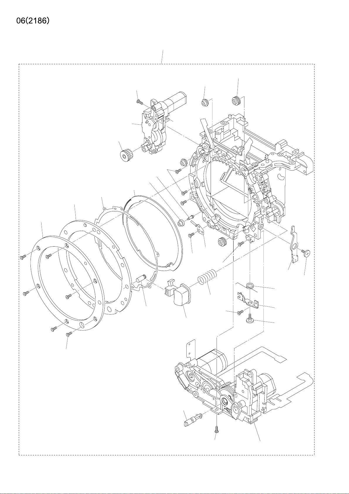
2186-0500-01 MIRROR BOX ASSY
(2186-0265-02) AF MODULE ASSY
(2186-0580-01) PENTA ASSY
[2186-0503-01] INF LCD HOLDER ASSY
[2186-0506-01] TOUKO ASSY
[2186-0584-01] DIOPTER ASSY
[2181-5016-01] FRESNAL SPRING
[2186-5022-01] SPC LIGHT SHIELD SHEET
2186-5025-01 VB WASHER A (0.05mm)
2186-5026-01 VB WASHER B (0.1mm)
2186-5027-01 VB WASHER C (0.15mm)
[2186-5028-01] VB WASHER D (STD WASHER) (0.2mm)
[2186-5048-02] PENTA PREVENTION SHEET
[2186-5805-02] FRESNAL
[2186-5820-01] SI SCREEN
ミラーボックスセット
AFモジュールセット
ペンタセット
IF LCDホルダーセット
投光セット
視度調セット
焦点板SP
SPC遮光シート
VBワッシャA
VBワッシャB
VBワッシャC
VBワッシャD
ペンタ防塵シート
焦点板
SIスクリーン
1
1
1
1
1
1
1
PARTS LIST
1
Some
1
1
1
[9384-2290-90]
[9747-1735-01] SCREW
[9747-1745-01] SCREW
(2162-2658-01) AF ADJUSTMENT SCREW
(2162-2659-01) AF ADJUSTMENT SP
(2082-5054-01) WASHER
(9384-2190-50) DOUBLE-FACED TAPE (PER ROLL)
(9747-1745-01) SCREW
POLYESTER TAPE (PER ROLL/60M) YELLOW
ポリエステルテープ
ねじ
ねじ
AF調整ねじ
AF調整SP
ワッシャ
両面テープ
ねじ
1
2
4
3
3
3
1
3
Page 17
2186-0500-01
(9747-1750-01)
(2186-2532-02)(2)
(2186-2533-02)(2)
(2163-1521-01)
(2186-1524-03)
(2186-0254-01)
(2186-2512-01)
(2186-2530-02)
(2186-1511-02)
(9747-1750-01)(2)
(2186-2535-01)
(2186-2534-01)
(2181-1515-01)
(2186-1813-01)
(9747-1745-01)
(2181-5123-01)(2)
(2162-1547-01)
(2186-1525-01)
See Page 7
(2186-1522-01)
(9749-1730-01)
(2186-1523-01)
(2186-1520-01)
(9761-2055-04)(6)
(2186-1545-02)
(2186-0526-01)
(9747-1745-01)
(2186-1521-01)
(2186-0521-01)
Page 18

(2186) 6
PART NO PART NAME QTY.
2186-0500-01 MIRROR BOX ASSY
(2186-0254-01) APERTURE ASSY
(2186-0521-01) AF CHARGE ASSY
(2186-0526-01) AF COUPLER ASSY
(2186-1511-02) A-MOUNT SPRING
(2181-1515-01) LENS LOCK PIN
(2186-1520-01) COUPLER LEVER
(2163-1521-01) BAYONET MOUNT
(2186-1521-01) COUPLER LEVER SHAFT
(2186-1522-01) COUPLER LINKAGE LEVER
(2186-1523-01) COUPLER LEVER SPRING
(2186-1524-03) MOUNT SPACER
(2186-1525-01) COUPLER LEVER ADJ SCREW
(2186-1545-02) LENS LOCK BUTTON
(2162-1547-01) LENS LOCK SP
ミラーボックスセット
絞り台板セット
AFチャージ台板セット
AFカプラーセット
リングSP
レンズロックピン
カプラーレバー
マウント
カプラーレバー軸
カプラー連動レバー
カプラーレバー付勢SP
マウントスペーサ
カプラーレバー調整ねじ
レンズロック釦
レンズロックSP
1
1
1
1
1
1
1
PARTS LIST
1
1
1
1
1
1
1
1
(2186-1813-01) MOUNT RAG PLATE 2
(2186-2512-01) APERTURE LINKAGE GEAR
(2186-2530-02) APERTURE RING
(2186-2532-02) ROLLER -A
(2186-2533-02) ROLLER -B
(2186-2534-01) ROLLER -C
(2186-2535-01) ROLLER -C SHAFT
(2181-5123-01) SCREW AF CHARGE BS PLT
(9747-1745-01) SCREW
(9747-1750-01) SCREW
(9749-1730-01) SCREW
(9761-2055-04) SCREW
マウント用ラグ板2
絞り連結ギヤ
絞りリング
リングローラーA
リングローラーB
リングローラーC
リングローラーC軸
AF/チャージ台板ねじ
ねじ
ねじ
ねじ
ねじ
1
1
1
2
2
1
1
2
2
3
1
6
Page 19
(2186-0150-01)
(9769-1740-01)
2186-0500-01
(2186-5110-01)
(9769-1730-01)
(2186-5110-01)
(9769-1730-01)
(2186-0514-01)
(9769-1740-01)
(2186-0180-01)
(2186-5151-01)
(2186-5109-01)
(9747-1745-01)(2)
[2186-5806-02]
(2186-1812-01)
(2186-0515-01)
(2181-5108-02)
(9747-1735-01)(4)
(2186-5101-01)
(2186-5107-02)
(2186-5102-01)
(9747-1440-01)
(2186-1543-02)
(2162-1544-01)
(2186-1542-01)
(2186-5112-01)
(2186-1548-01)
Page 20

(2186) 7
PART NO PART NAME QTY.
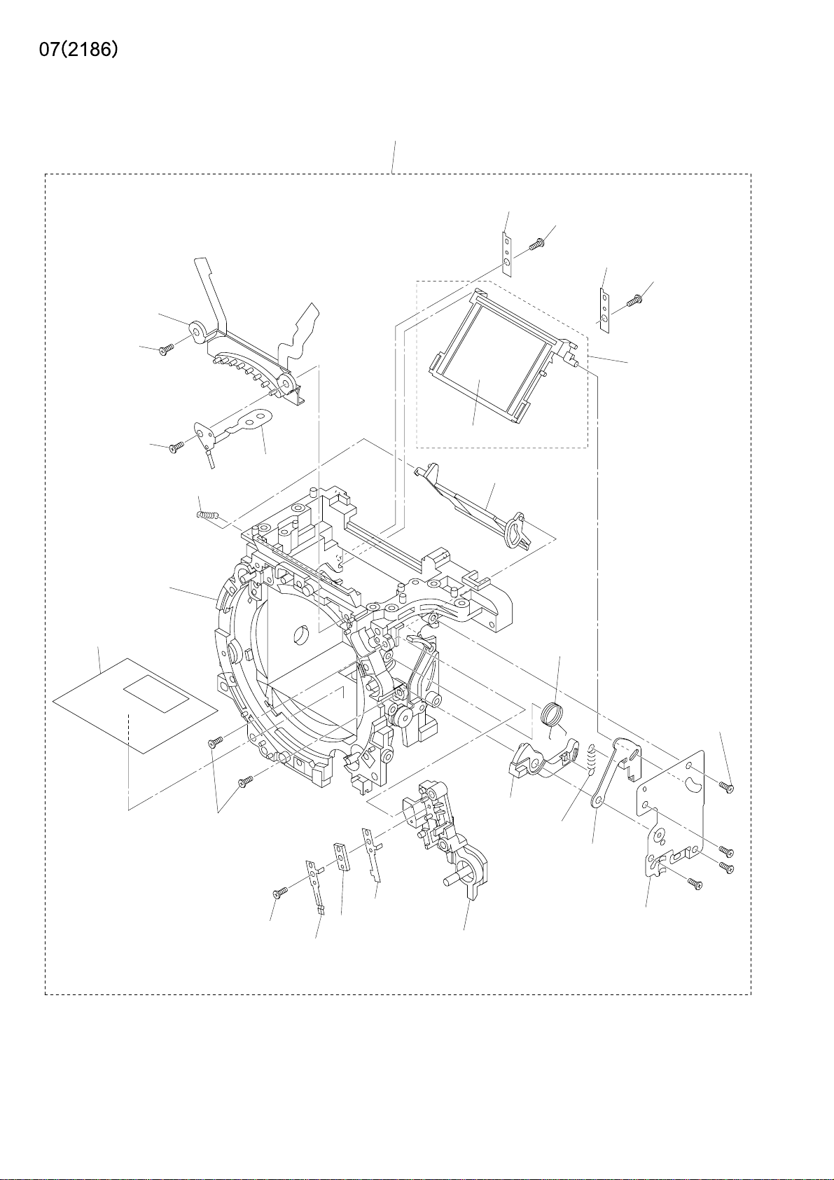
2186-0500-01 MIRROR BOX ASSY
(2186-0150-01) BL CONTACT HOLDER ASSY
(2186-0180-01) FRONT FRAME ASSY
(2186-0514-01) MAIN MIRROR HOLDER UNIT
[2186-5806-02] MAIN MIRROR
(2186-0515-01) SUB MIRROR HOLDER ASSY
(2186-1542-01) SLLK CONTACT A
(2186-1543-02) SLLK CONTACT B
(2162-1544-01) SLLK CONTACT SPACER
(2186-1548-01)
(2186-1812-01) MOUNT RAG PLATE1
(2186-5101-01) MIRROR DRIVING LEVER
(2186-5102-01) MAIN MIRROR DRIVING LEVER
(2186-5107-02) MIRROR OVER CHARGE SP
(2181-5108-02) MIRROR DRIVE SP
LENS LOCK BUTTON HOLDING BASE PLATE
ミラーボックスセット
BL接片ホルダーセット
前枠セット
主ミラーホルダーセット
主ミラー
サブミラーホルダーセット
SLLK接片A
SLLK接片B
SLLK接片スペーサー
レンズロック釦保持台板
マウント用ラグ板1
ミラー駆動レバー
主ミラー駆動レバー
ミラーオーバーチャージSP
ミラー駆動SP
1
1
1
1
1
1
1
PARTS LIST
1
1
1
1
1
1
1
1
(2186-5109-01) SUB MIRROR DRIVING SP
(2186-5110-01) M.MIRROR HOLDER PRESSING PLT
(2186-5112-01) MIRROR DRIVING BASE PLT
(2186-5151-01) FLARE CUTTER SHEET
(9747-1440-01) SCREW
(9747-1735-01) SCREW
(9747-1745-01) SCREW
(9769-1730-01) SCREW
(9769-1740-01) SCREW
サブミラー駆動SP
主ミラーホルダー押え板
ミラー駆動台板
フレア防止シート
ねじ
ねじ
ねじ
ねじ
ねじ
1
2
1
1
1
4
2
2
2
Page 21

9761-2055-01
2186-1088-01
9384-2290-90
(9X15mm)
2186-1153-02
2186-1151-02
9769-1730-01
2186-1156-01
9747-1735-01
9747-1735-01
2186-0155-01
2186-1072-01
2186-1065-02
2186-1159-01
2186-0154-01
2186-1071-03
9747-1740-01
9749-2035-01(2)
2186-1002-04
9384-2191-00
(6X20mm)
2186-0414-02
2186-4508-02
2186-1086-01
9747-1750-01
2186-1087-01
2186-1082-02(2)
9747-1730-01(2)
2186-1083-01
2186-1081-02
9749-1735-15
9353-4361-13
9747-1740-01(2)
2186-0473-01
2186-0427-03
9747-1740-01(2)
2186-1073-01
2186-1041-02
2186-1042-02
2186-1040-02
2186-0420-03
9384-2190-50(3)
(5X5mm)
Page 22

(2186) 8
PART NO PART NAME QTY.
2186-0154-01 CF CARD COVER HINGE SHAFT-A ASSY
2186-0155-01 CF CARD COVER HINGE SHAFT-B ASSY
2186-0414-02 GYRO FPC ASSY
2186-0420-03 SW FPC-2 ASSY
2186-0427-03 DC JACK PCB ASSY
2186-0473-01 FLASH PCB ASSY
2186-1002-04 SUS PLATE G
2186-1040-02 LCD HOLDER
2186-1041-02 LCD WINDOW
2186-1042-02 LCD WINDOW ATTACHMENT SHEET
2186-1065-02 EYELET G
2186-1071-03 BATTERY CHAMBER
2186-1072-01 BATTERY CHAMBER SHEET
2186-1073-01 BATTERY FORCING SP
2186-1081-02 BATTERY LOCK PLATE
2186-1082-02 BATTERY CONTACT
2186-1083-01 BATTERY LOCK PLATE FORCING SP
CFカードカバー軸Aセット
CFカードカバー軸Bセット
ジャイロフレキセット
SWフレキ2セット
DCジャック基板セット
フラッシュ基板セット
サブシャーシG
LCDホルダー
LCD窓
LCD窓貼付けシート
吊環G
電池室
電池室シート
電池付勢SP
電池ロック爪
電池接片
電池ロック爪付勢SP
1
1
1
1
1
1
1
1
1
1
1
1
1
1
1
2
1
PARTS LIST
2186-1086-01 FLASH PCB GAP HOLDER
2186-1087-01 LUG PLATE 1
2186-1088-01 LUG PLATE 2
2186-1151-02 CF CARD COVER
2186-1153-02 CF CARD COVER CLICK PLATE
2186-1156-01 CF CARD DISPLAY SHEET
2186-1159-01 CF CARD COVER SP
2186-4508-02 GYRO FPC TAPE
9353-4361-13 LCD 101
9384-2190-50 DOUBLE-FACED TAPE (PER ROLL)
9384-2191-00 DOUBLE-FACED TAPE (PER ROLL)
9384-2290-90
9747-1730-01 SCREW
9747-1735-01 SCREW
9747-1740-01 SCREW
9747-1750-01 SCREW
9749-1735-15 SCREW
POLYESTER TAPE (PER ROLL/60M) YELLOW
フラッシュ基板絶縁ホルダー
ラグ板1
ラグ板2
CFカード蓋
CFカード蓋クリック板
CFカード表示シート
CFカード蓋SP
ジャイロフレキテープ
LCD101
両面テープ
両面テープ
ポリエステルテープ
ねじ
ねじ
ねじ
ねじ
ねじ
1
1
1
1
1
1
1
1
1
3
1
1
2
2
5
1
1
9749-2035-01 SCREW
9761-2055-01 SCREW
9769-1730-01 SCREW
ねじ
ねじ
ねじ
2
1
1
Page 23
(2186-1334-02)(-650)
(2186-1479-02)(-090,-100,-300,-600)
(2186-1477-01)
(2186-1317-01)(-650)
(2186-1401-01)(-090,-100,-300,-600)
(2186-0166-01)
2186-0131-01(-650)
2186-0135-01(-090,-100,-300,-600)
(9747-1745-04)(2)(-650)
(9747-1745-15)(2)(-090,-100,-300,-600)
(2186-1335-01)(-650)
(2186-1601-02)(-090,-100,-300,-600)
(2186-1609-01)
(2186-1613-01)
(2186-1318-01)
(-650)
(2186-1403-02)
(-090,-100,-300,-600)
(2186-1402-03)
(2186-1424-01)
(2186-1404-01)
[2186-1603-01]
(2186-1602-02)
(2186-1608-01)(2)
(2089-1607-02)
(9747-1745-15)(2)
(2089-1620-01)
(2186-1333-02)
(-650)
(2186-1474-02)
(2089-1621-01)
(2186-1332-02)
(-650)
(2186-1473-02)
(-090,-100,-300,-600)
(2186-1477-01)
(2186-1331-02)
(-650)
(2186-1470-01)
(-090,-100,-300,-600)
(2186-1330-03)
(-650)
(2186-1469-04)
(-090,-100,-300,-600)
(-090,-100,-300,-600)
(9721-0120-50)
(2181-1305-01)
(2162-1477-01)(2)
(9758-0150-00)(2)
(2186-1407-01)
(2186-1410-01)
(9748-2045-01)
(2186-1610-01)
(2186-1611-01)
(2162-1477-01)(2)
(9758-0150-00)(2)
(2186-1471-01)
(2186-1475-01)
(9747-1735-01)(2)
(2186-1481-02)
(9747-1730-01)
Page 24

(2186) 9
PART NO PART NAME QTY.
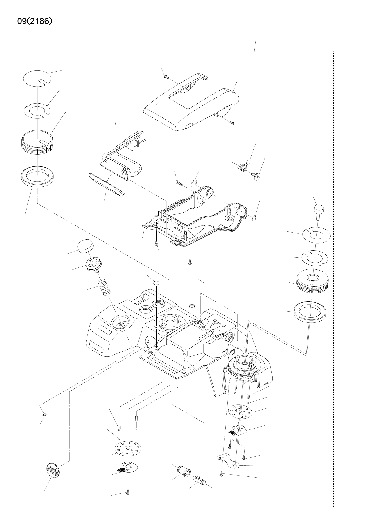
2186-0131-01 TOP COVER ASSY (-650)
2186-0135-01 TOP COVER ASSY (-090, -100, -300, -600)
(2186-0166-01) REFLECTOR ASSY
[2186-1603-01] FLASH PANEL
(2181-1305-01) VI EMBLEM
(2186-1317-01) MODE DIAL (-650)
(2186-1401-01) MODE DIAL (-090, -100, -300, -600)
(2186-1318-01) MODE DIAL DECORATION RING (-650)
(2186-1403-02)
MODE DIAL DECORATION RING (-090, -100, -300, -600)
(2186-1330-03) WB DIAL DECORATION RING (-650)
(2186-1469-04)
WB DIAL DECORATION RING (-090, -100, -300, -600)
(2186-1331-02) WB DIAL (-650)
(2186-1470-01) WB DIAL (-090, -100, -300, -600)
(2186-1332-02) WB DIAL NAME PLATE (-650)
(2186-1473-02)
WB DIAL NAME PLATE (-090, -100, -300, -600)
(2186-1333-02) WB BUTTON (-650)
(2186-1474-02) WB BUTTON (-090, -100, -300, -600)
(2186-1334-02) MODE DIAL NAME PLATE (-650)
(2186-1479-02)
MODE DIAL NAME PLATE (-090, -100, -300, -600)
(2186-1335-01) FLASH CASE (UPPER) (-650)
(2186-1601-02)
FLASH CASE (UPPER) (-090, -100, -300, -600)
(2186-1402-03) RELEASE BUTTON CAP
(2186-1404-01) RELEASE BUTTON SP
(2186-1407-01) MODE DIAL CLICK PLATE
(2186-1410-01) MODE DIAL CONTACT
(2186-1424-01) RELEASE BUTTON
(2186-1471-01) WB DIAL CLICK PLATE
(2186-1475-01) WB DIAL DETECT CONTACT
(2162-1477-01) DIAL CLICK SP
(2186-1477-01) WB / MODE NAME PLATE TAPE
(2186-1481-02) WB BUTTON SP
(2186-1602-02) FLASH CASE (BOTTOM)
(2089-1607-02) SCREW
(2186-1608-01) FLASH CUSHION RUBBER
(2186-1609-01) F SNAP ACTION SP
(2186-1610-01) ROTATION AXIS (L)
(2186-1611-01) ROTATION AXIS (R)
(2186-1613-01) SNAP SUPPORTING SCREW
(2089-1620-01) C-RING
(2089-1621-01) C-RING
(9721-0120-50) E-RING
(9747-1730-01) SCREW
(9747-1735-01) SCREW
(9747-1745-04) SCREW (-650)
(9747-1745-15) SCREW (-650)
(9747-1745-15) SCREW (-090, -100, -300, -600)
(9748-2045-01) SCREW
(9758-0150-00) STEEL BALL
上カバーセット
上カバーセット
発光部セット
発光パネル
VIエンブレム
モードダイヤル
モードダイヤル
モードダイヤル化粧リング
モードダイヤル化粧リング
WBダイヤル化粧リング
WBダイヤル化粧リング
WBダイヤル
WBダイヤル
WBダイヤル文字板
WBダイヤル文字板
WB釦
WB釦
モードダイヤル文字板
モードダイヤル文字板
発光部ケース(上)
発光部ケース(上)
レリーズ釦キャップ
レリーズ釦SP
モードダイヤルクリック板
モードダイヤル接片
レリーズ釦
WBダイヤルクリック板
WBダイヤル接片
露出ダイヤルクリックSP
WB文字板テープ
WB釦SP
発光部ケース(下)
ねじ
フラッシュクッション
フラッシュスナップアクションSP
回転軸L
回転軸R
ねじ
Cリング
Cリング
Eリング
ねじ
ねじ
ねじ
ねじ
ねじ
ねじ
スチールボール
1
1
1
1
1
1
1
PARTS LIST
1
1
1
1
1
1
1
1
1
1
1
1
4
2
1
1
1
2
1
1
1
1
1
1
1
1
2
2
2
4
1
4
Page 25
(9372-3960-02)
(2186-1443-01)
(9747-1740-01)(4)
2186-0131-01(-650)
2186-0135-01(-090,-100,-300,-600)
(9747-1740-01)(3)
(2186-1441-02)
(9384-2190-50)(3)
(5X5mm)
(2186-0146-01)
(9384-2190-50)(2)
(5X5mm)
A
(2186-1327-03)
(-650)
(2186-1440-03)
(-090,-100,-300,-600)
(2186-1320-03)
(-650)
(2186-1421-02)
(-090,-100,-300,-600)
(9747-1745-01)(2)
(9384-2190-50)
(3X6mm)
(9761-2060-01)(2)
(9384-2190-50)
(5X5mm)
(9384-2190-50)
(5X5mm)
(9384-2191-00)
(10X10mm)
(9761-2060-01)(2)
(2186-1625-02)
A
(2186-1612-01)
(2186-1476-01)
(9384-2191-00)
(10X10mm)
(2186-0407-02)
(2186-1328-01)(2)
(-650)
(2186-1442-01)(2)
(2186-1321-01)
(-650)
(2186-1422-01)
(-090,-100,-300,-600)
(-090,-100,-300,-600)
(2186-1322-03)(-650)
(2186-1425-02)(-090,-100,-300,-600)
(2186-1120-02)
(2186-1614-02)
(2077-0145-01)
(9747-1735-01)
(2186-1427-01)
(2186-1426-02)
Page 26

(2186) 10
PART NO PART NAME QTY.
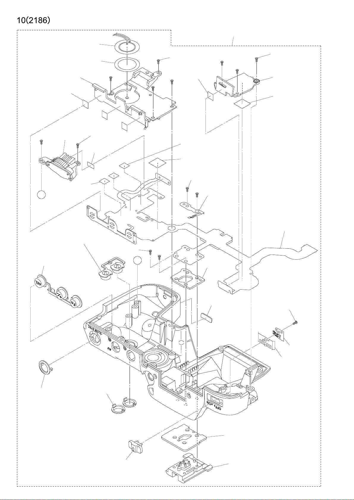
2186-0131-01 TOP COVER ASSY (-650)
2186-0135-01 TOP COVER ASSY (-090, -100, -300, -600)
(2077-0145-01) FLASH ACC SHOE SET
(2186-0146-01) FRONT DIAL HOLDER ASSY
(2186-0407-02) TOP COVER FPC ASSY
(2186-1120-02) SELF WINDOW
(2186-1320-03) 3 COMBINED BUTTON (-650)
(2186-1421-02)
3 COMBINED BUTTON (-090, -100, -300, -600)
(2186-1321-01) AEL BUTTON RING (-650)
(2186-1422-01) AEL BUTTON RING (-090, -100, -300, -600)
(2186-1322-03) MAIN SW CHANGEOVER LEVER (-650)
(2186-1425-02)
MAIN SW CHANGEOVER LEVER (-090, -100, -300, -600)
(2186-1327-03) 2 COMBINED BUTTON (-650)
(2186-1440-03)
2 COMBINED BUTTON (-090, -100, -300, -600)
(2186-1328-01) MODE BUTTON RING (-650)
(2186-1442-01)
MODE BUTTON RING (-090, -100, -300, -600)
上カバーセット
上カバーセット
アクセサリーシューセット
前ダイヤルホルダーセット
上カバーフレキセット
セルフ窓
3連釦
3連釦
AEL釦リング
AEL釦リング
メインSWレバー
メインSWレバー
2連釦
2連釦
モード釦リング
モード釦リング
1
1
1
1
1
1
PARTS LIST
1
1
1
2
(2186-1426-02)
(2186-1427-01)
MAIN SW CHANGEOVER LEVER CLICK PLATE
MAIN SW CHANGEOVER LEVER CONTACT
(2186-1441-02) MODE DIAL PLATE
(2186-1443-01) BUZZER ATTACHMENT TAPE
(2186-1476-01) WB DIAL BASE PLATE
(2186-1612-01) HOT SHOE MOUNTING PLATE
(2186-1614-02) HOT SHOE PLATE
(2186-1625-02) PU DETECT CONTACT
(9372-3960-02) BUZZER
(9384-2190-50) DOUBLE-FACED TAPE (PER ROLL)
(9384-2191-00) DOUBLE-FACED TAPE (PER ROLL)
(9747-1735-01) SCREW
(9747-1740-01) SCREW
(9747-1745-01) SCREW
(9761-2060-01) SCREW
メインSWレバークリック板
メインSW接片
モードダイヤル台板
ブザー貼付けテープ
WBダイヤル台板
シュー取付板
シュー敷板
PU検知接片
ブザー
両面テープ
両面テープ
ねじ
ねじ
ねじ
ねじ
1
1
1
1
1
1
1
1
1
8
2
1
7
2
4
Page 27
2186-0121-01(-090,-100,-300,-600)
2186-0122-01(-650)
(2186-1115-01)
(2186-1119-02)
(9767-1435-01)
(2186-1133-01)
(2186-1132-01)
(2186-1445-01)
(2186-1446-01)
(2186-4511-01)
(2186-1336-01)
(-650)
(2166-1485-01)
(-090,-100,-300,-600)
(9384-2290-90)
(9X20mm)
2186-0110-01
(9747-1740-01)
(2181-1419-03)
(2186-1420-02)
(2186-1417-02)
(2186-1116-01)
(2186-1106-01)
(2186-1107-01)
(2186-1133-01)
(2186-1132-01)
(2186-1418-03)
(2186-1329-03)(-650)
(2186-1444-02)(-090,-100,-300,-600)
(2186-1431-02)
(2186-1433-01)
(2186-1430-03)
(2186-1432-01)
(2186-1143-02)
(2186-1436-01)(4)
(2186-1435-02)(4)
(2186-1433-01)(4)
(9747-1730-01)
(2186-1145-01)
(2186-1133-01)
(2186-1132-01)
(2186-2940-01)(2)
(2186-1133-01)
(2186-1132-01)
Page 28

(2186) 11
PART NO PART NAME QTY.
2186-0110-01 BACK COVER ASSY
(2186-1106-01) BACK COVER RUBBER
(2186-1107-01) BACK COVER ATTACHMENT TAPE
(2186-1132-01) FRONT COVER BOTTOM RUBBER
(2186-1133-01) DOUBLE SIDE TAPE
(2186-1143-02) DC JACK COVER
(2186-1145-01) DC COVER PIN
(2186-1417-02) ACCESS LAMP WINDOW
(2186-1418-03) ANTI SHAKE SW CHANGEOVER LEVER
(2181-1419-03) TEBURE CLICK PLATE
(2186-1420-02) ANTI SHAKE SW CONTACT
(2186-1430-03) CROSS BUTTON
(2186-1431-02) DECISION BUTTON
(2186-1432-01) CROSS BUTTON SP
(2186-1433-01) DECISION BUTTON SP
(2186-1435-02) 4 COMBINED BUTTON
(2186-1436-01)
4 COMBINED BUTTON DECORATION RING
後カバーセット
後カバーゴム
後カバーゴム貼付けテープ
底面ゴム
底面ゴムテープ
DCジャックカバー
DCカバーピン
アクセスランプ窓
手振れSWレバー
手振れクリック板
手振れSW接片
十字釦
決定釦
十字釦SP
決定釦SP
4連釦
4連釦飾りリング
1
1
1
2
2
1
1
1
1
1
1
1
1
1
5
4
4
PARTS LIST
(2186-2940-01) TAPE
(9747-1730-01) SCREW
(9747-1740-01) SCREW
2186-0121-01
2186-0122-01 FRONT COVER ASSY (-650)
(2186-1115-01) RUBBER DOUBLE SIDE TAPE A
(2186-1116-01) RUBBER DOUBLE SIDE TAPE B
(2186-1119-02) GRIP COVER
(2186-1132-01) FRONT COVER BOTTOM RUBBER
(2186-1133-01) DOUBLE SIDE TAPE
(2186-1329-03) AF/M CHANGEOVER LEVER (-650)
(2186-1444-02)
(2186-1336-01) PREVIEW BUTTON (-650)
(2166-1485-01) PREVIEW BUTTON (-090, -100, -300, -600)
(2186-1445-01) AF/M CHANGEOVER CONTACT
(2186-1446-01) MAIN SW CLICK PLATE
FRONT COVER ASSY (-090, -100, -300, -600)
AF/M CHANGEOVER LEVER (-090, -100, -300, -600)
テープ
ねじ
ねじ
前カバーセット
前カバーセット
グリップゴム両面テープA
グリップゴム両面テープB
グリップゴム
底面ゴム
底面ゴムテープ
AF/M切替えレバー
AF/M切替えレバー
プレビュー釦
プレビュー釦
AF/M切替え接片
AF/Mクリック板
2
1
1
1
1
1
1
2
2
1
1
1
1
(2186-4511-01) INSULATING SHEET
(9384-2290-90)
(9767-1435-01) SCREW
POLYESTER TAPE (PER ROLL/60M) YELLOW
絶縁シート
ポリエステルテープ
ねじ
1
1
1
Page 29
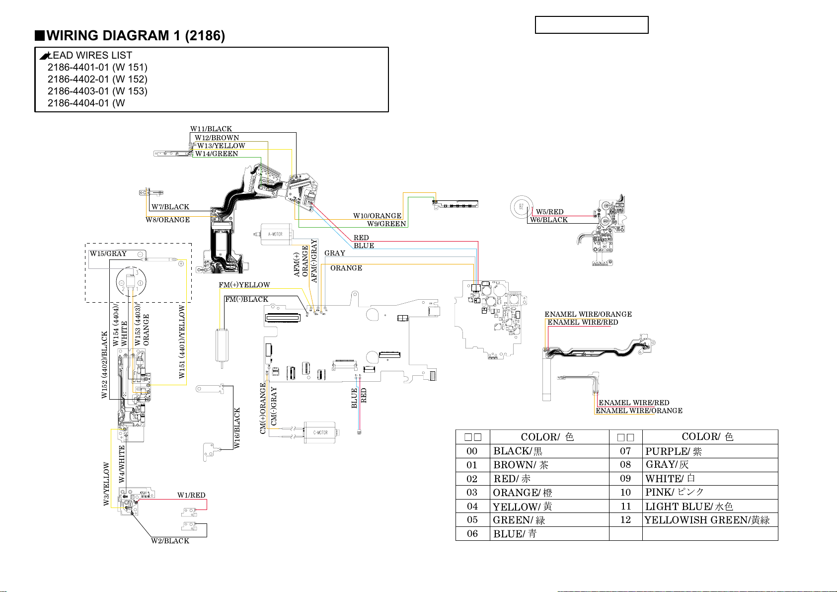
WIRING DIAGRAM 1 (2186)
■
LEAD WIRES LIST
2186-4401-01 (W 151)
2186-4402-01 (W 152)
2186-4403-01 (W 153)
2186-4404-01 (W 154)
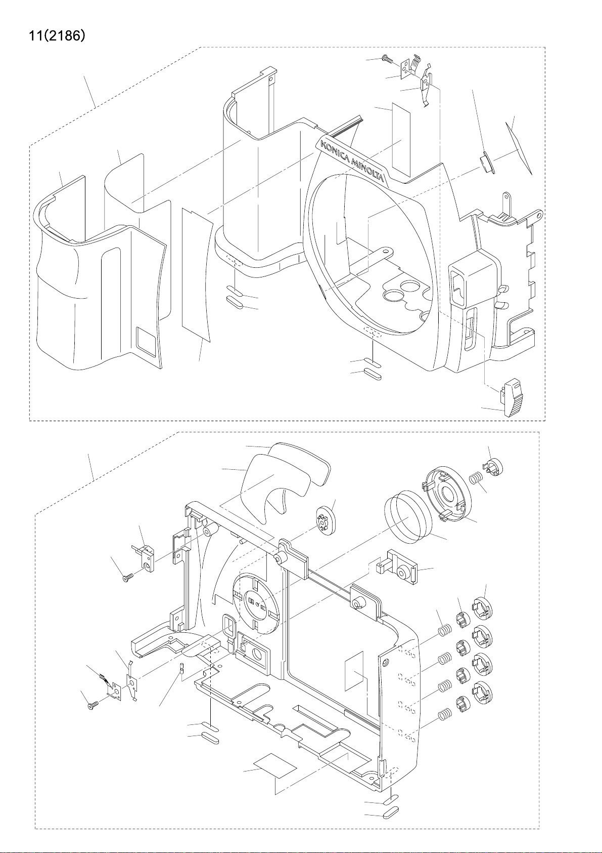
EYE PIECE FRAME
ASSY (0134)
9391-0807 9391-1207-
W11/BLACK
W12/BROWN
W13/YELLOW
W14/GREEN
□□
(W 5, 6, 7, 8, 9, 10, 11, 12, 13, 14)
□□
(W 1, 2, 3, 4, 15, 16)
PARTS LIST
12 (2186)
SLLK CONTACT A (1542)
SLLK CONTACT B
(1543)
REFLECTOR ASSY (0166)
W15/GRAY
W154 (4404)/
W152 (4402)/BLACK
W3/YELLOW
DC JACK PCB
ASSY (0473)
W7/BLACK
W8/ORANGE
W153 (4403)/
ORANGE
WHITE
W4/WHITE
W2/BLACK
LUG PLATE 2 (1088)
W151 (4401)/YELLOW
FLASH PC
ASSY (0473)
W1/RED
AF CHARGE
ASSY (0521)
FM(+)YELLOW
FM(-)BLACK
APERTURE ASSY (0254)
CM(-)GRAY
CM(+)ORANGE
W16/BLACK
LUG PLATE 1 (1087)
BATTERY CONTACT (1082)
AF CHARGE ASSY (0521)
I/O FLEXIBLE ASSY
(0406)
GRAY
AFM(+)
ORANGE
ORANGE
AFM(-)GRAY
W10/ORANGE
W9/GREEN
RED
BLUE
MAIN PCB ASSY (0401)
RED
BLUE
LCD HARNESS (0442)
INF LCD HOLDER
ASSY (0503)
POWER SUPPLY
HARNESS (0441)
00
01
02
03
04
05
06
BUZZER (9372-3960)
W5/RED
W6/BLACK
DCDC PCB ASSY (0402)
ENAMEL WIRE/ORANGE
COLOR/
BLACK/
BROWN/
RED/
ORANGE/
YELLOW/
GREEN/
BLUE/
TOP COVER FPC ASSY (0407)
ENAMEL WIRE/RED
SLIDER ASSY (0901)
ENAMEL WIRE/RED
ENAMEL WIRE/ORANGE
07
08
09
10
11
12
COLOR/
PURPLE/
GRAY/
WHITE/
PINK/
LIGHT BLUE/
YELLOWISH GREEN/
Page 30

REPAIR GUIDE
(2186) 1
REPAIR GUIDE
This repair guide section contains the disassembly and adjustment procedures.
For the assembly procedure, follow the reverse procedure.
SYMBOLS
■:Cautions and keypoints
: Grease
: Adhesive
: Tool
CONTENTS Page CONTENTS Page
■Precautions --------------------------------------------- 2
■Chemicals ----------------------------------------------- 2
■Plastic parts -------------------------------------------- 2
■PCBs ----------------------------------------------------- 2
■Unleaded solder ---------------------------------------- 2
■Discharge------------------------------------------------ 3
■To activate without exterior parts ----------------- 3
1. Disassembly of the exterior parts ------------------ 4
■ Wires arrangement----------------------------------- 6
2. Disassembly of the I/O FPC ASSY,
MAIN PCB ASSY ---------------------------------- 8
3. Disassembly of the SUB PLATE L,
BATTERY CHAMBER--------------------------- 11
4. Disassembly of the CCD ASSY,
SHUTTER ASSY----------------------------------13
■CCD inclination adjustment / repair-------------16
5. Disassembly-1 of the MIRROR BOX ASSY -----17
6. Disassembly-2 of the MIRROR BOX ASSY -----19
7. Disassembly-3 of the MIRROR BOX ASSY -----22
8. Disassembly of the BATTERY CHAMBER,
LCD 101 ---------------------------------------------24
9. Disassembly of the TOP COVER ASSY---------- 27
10. Disassembly of the FRONT COVER ASSY,
BACK COVER ASSY -----------------------------31
■Required adjustment, setting and confirmation
items after repairing (exchanging parts)----- 33
■Related adjustment and
required setting items ----------------------------34
■Viewfinder Back Adjustment ---------------------- 35
■Preparing the 2186 adjustment program -------36
■Starting up the 2186 adjustment program
(in the adjustment mode). -----------------------37
■Adjustment of the PI-PR---------------------------- 38
■Adjustment of the frequency for
camera shaking (FREQUENCY) --------------38
■Adjustment of the servo for
camera shaking (SERVO) ----------------------- 38
■Adjustment of the gyro for
camera shaking (GYRO) ------------------------39
■Adjustment of CCD Vsub voltage (VSUB) ------ 39
■Setting for the adjustment of
CCD AORI & CENTER -------------------------- 40
■Adjustment / Checking of
CCD AORI & CENTER -------------------------- 41
■Manual Set SS & X-Sync. Time-lag Check-----43
■Adjustment Manual Set SS ------------------------44
■Preparation before AF adjustment --------------- 45
■AF Area Adjustment---------------------------------46
■Pitch Yaw Adjustment ------------------------------47
■FLATNESS Adjustment---------------------------- 48
■EZ Check / Adjustment ----------------------------- 48
■EZ SH I F T---------------------------------------------- 51
■Aperture Preset Check / Adjustment ------------52
■Check / Adjustment of the AE (AE) --------------53
■Sensitivity adjustment (CCD GAIN)-------------54
■Adjustment of the defective pixel
(DEFECT PIXEL)--------------------------------- 54
■Adjustment of white balance (WB) --------------- 55
■Adjustment of the camera shaking
compensation (SHAKE GAIN) -----------------56
■FLASH LEVEL SHIFT ----------------------------- 57
■Setting of Destination (DESTINATION)-------- 57
■CAMERA LOG ---------------------------------------58
■LCD All Segment On ------------------------------- 58
■Light Source-A Maintenance ----------------------59
■Error code on adjustment program--------------- 60
■Measuring instrument ------------------------------62
■Subsidiary Materials---------------------------------62
Page 31

2 (2186)
Chemicals
Handle chemicals of high volatility with care, use of which will affect to your health and environment.
1. Store them sealed in a specific place to prevent exposure to high temperature or direct sunlight.
2. Avoid dividing them into small containers and prevent vaporization.
3. Keep containers sealed when not in use.
4. Avoid using them as much as possible. When required, remove only required amount from the
container to make full use.
Plastic parts
1. When cleaning plastic parts, use cleaning paper or cloth. Never use thinner, ketone, ether.
2. When installing plastic parts, insert the specific screws vertically to the parts. (Be careful not to
tighten too much.
PCBs
Since PCBs use MOS IC, you must reduce static electricity. When repairing a PCB itself, or when
wiring, please perform your work as illustrated below.
If grounding is impossible, connect a cable to a steel desk or shelf.
Unleaded solder
REPAIR GUIDE
This model uses lead-free solder.
The cautions on use:
1. A soldering iron tip temperature of 280 - 350℃ is sufficient, but when it cannot melt solder, use a
higher temperature for a short period of time.
2. Be sure to control soldering iron tips used for lead-free solder and those for leaded solder so they are
managed separately.
This is because mixing lead-free solder and leaded solder will cause detachment phenomenon.
■■
■ Precautions
■■
Keep touching the conductiveKeep touching the conductive
Keep touching the conductive
Keep touching the conductiveKeep touching the conductive
mat while you work.mat while you work.
mat while you work.
mat while you work.mat while you work.
Conductive MatConductive Mat
Conductive Mat
Conductive MatConductive Mat
GNDGND
GND
GNDGND
1M1M
1M
1M1M
ΩΩ
Ω
ΩΩ
Page 32

(2186) 3
REPAIR GUIDE
Discharge
Before disassembly, be sure to discharge the main condenser in the following manner.
WHITEWHITE
WHITE
WHITEWHITE
YELLOWYELLOW
YELLOW
YELLOWYELLOW
Short-circuit with discharger or resistor of 200-300 ohm/3w.
Check voltage to make sure it is discharged.
To activate without exterior parts
Short-circuit the pattern -a of I/O FLEXIBLE ASSY with solder.
When using replacement I/O FLEXIBLE ASSY, no need to short these patterns because it has pattern-b.
*Before installing BACK COVER ASSY, be sure to unsolder the pattern-a or to cut the pattern-b.
aa
a
aa
bb
b
bb
I/O FLEXIBLE ASSYI/O FLEXIBLE ASSY
I/O FLEXIBLE ASSY
CutCut
Cut
CutCut
I/O FLEXIBLE ASSYI/O FLEXIBLE ASSY
Page 33

4 (2186)
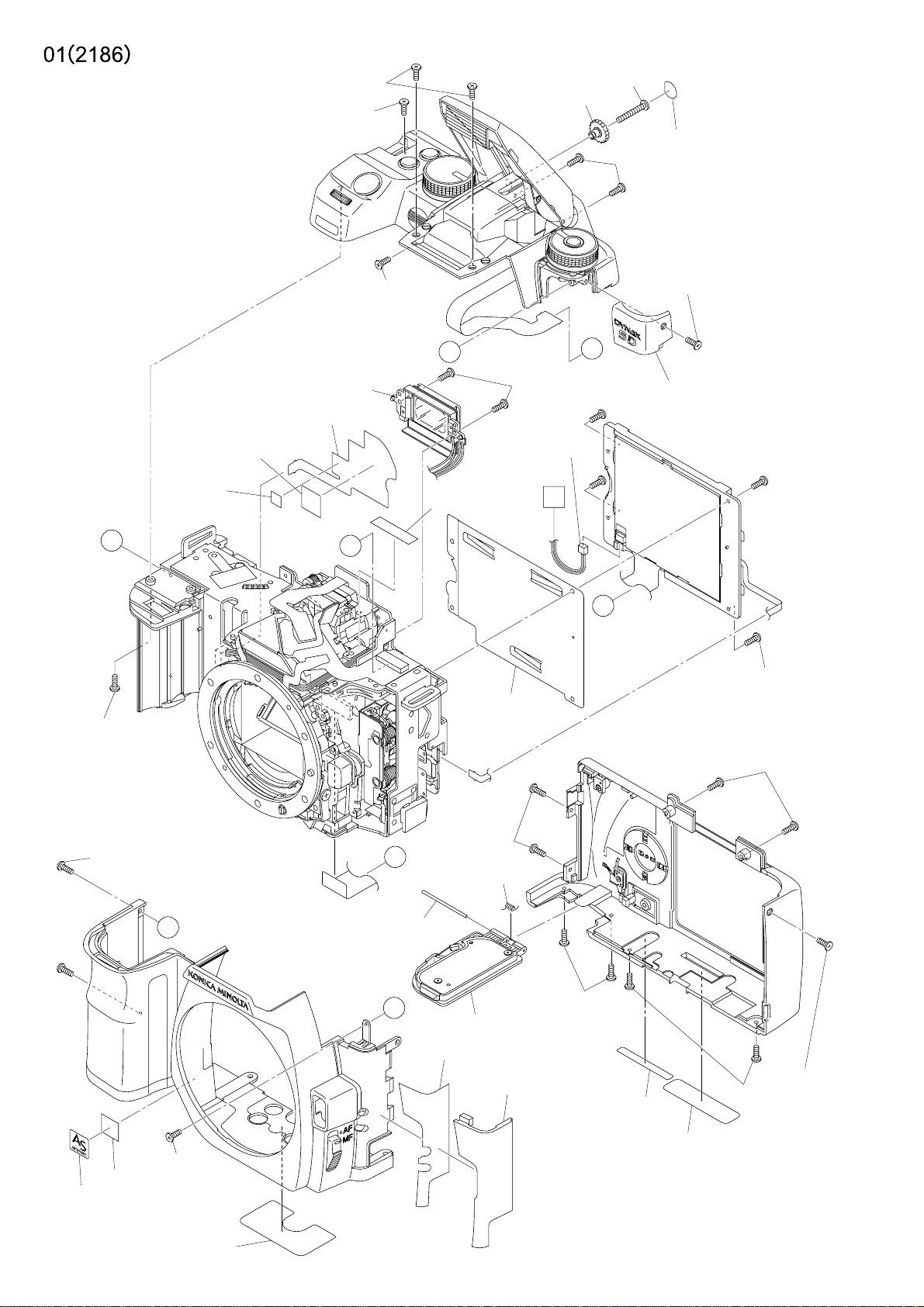
1. Disassembly of the exterior parts
Disassemble it in order of step 1to 8.
REPAIR GUIDE
9611-2035-04(-650)9611-2035-04(-650)
9611-2035-04(-650)
9611-2035-04(-650)9611-2035-04(-650)
9611-2035-159611-2035-15
9611-2035-15
9611-2035-159611-2035-15
(-090,-100,-300,-600)(-090,-100,-300,-600)
(-090,-100,-300,-600)
(-090,-100,-300,-600)(-090,-100,-300,-600)
TOP COVER ASSYTOP COVER ASSY
TOP COVER ASSY
TOP COVER ASSYTOP COVER ASSY
EYE PIECE FRAME ASSYEYE PIECE FRAME ASSY
EYE PIECE FRAME ASSY
EYE PIECE FRAME ASSYEYE PIECE FRAME ASSY
■■
Fig. 4Fig. 4
■
Fig. 4
■■
Fig. 4Fig. 4
9384-2191-009384-2191-00
9384-2191-00
9384-2191-009384-2191-00
(10x10mm)(10x10mm)
(10x10mm)
(10x10mm)(10x10mm)
9384-2190-509384-2190-50
9384-2190-50
9384-2190-509384-2190-50
(5x5mm)(5x5mm)
(5x5mm)
(5x5mm)(5x5mm)
B
9747-1755-04(2)(-650)9747-1755-04(2)(-650)
9747-1755-04(2)(-650)
9747-1755-04(2)(-650)9747-1755-04(2)(-650)
9747-1755-15(2)9747-1755-15(2)
9747-1755-15(2)
9747-1755-15(2)9747-1755-15(2)
(-090,-100,-300,-600)(-090,-100,-300,-600)
(-090,-100,-300,-600)
(-090,-100,-300,-600)(-090,-100,-300,-600)
⑤⑤
⑤
⑤⑤
■■
Fig. 2Fig. 2
■
Fig. 2
■■
Fig. 2Fig. 2
See Page 27.See Page 27.
See Page 27.
See Page 27.See Page 27.
SW FPC-1 ASSYSW FPC-1 ASSY
SW FPC-1 ASSY
SW FPC-1 ASSYSW FPC-1 ASSY
⑦⑦
⑦
⑦⑦
9744-1620-019744-1620-01
9744-1620-01
9744-1620-019744-1620-01
⑧⑧
⑧
⑧⑧
C
A
9611-1625-01(2)9611-1625-01(2)
9611-1625-01(2)
9611-1625-01(2)9611-1625-01(2)
See Page 8.See Page 8.
See Page 8.
See Page 8.See Page 8.
2098-50452098-5045
2098-5045
2098-50452098-5045
9761-1470-019761-1470-01
9761-1470-01
9761-1470-019761-1470-01
50415041
5041
50415041
9744-1665-04(2)(-650)9744-1665-04(2)(-650)
9744-1665-04(2)(-650)
9744-1665-04(2)(-650)9744-1665-04(2)(-650)
9744-1665-15(2)9744-1665-15(2)
9744-1665-15(2)
9744-1665-15(2)9744-1665-15(2)
(-090,-100,-300,-600)(-090,-100,-300,-600)
(-090,-100,-300,-600)
(-090,-100,-300,-600)(-090,-100,-300,-600)
VERSION PLTVERSION PLT
VERSION PLT
VERSION PLTVERSION PLT
9747-1740-04(-650)9747-1740-04(-650)
9747-1740-04(-650)
C
A
9747-1740-04(-650)9747-1740-04(-650)
③③
③
③③
9747-1740-159747-1740-15
9747-1740-15
9747-1740-159747-1740-15
(-090,-100,-300,-600)(-090,-100,-300,-600)
(-090,-100,-300,-600)
(-090,-100,-300,-600)(-090,-100,-300,-600)
LCD 101LCD 101
LCD 101
LCD 101LCD 101
■■
■
■■
See Page 24.See Page 24.
See Page 24.
See Page 24.See Page 24.
9744-1625-01(4)9744-1625-01(4)
9744-1625-01(4)
9744-1625-01(4)9744-1625-01(4)
Fig. 3Fig. 3
Fig. 3
Fig. 3Fig. 3
9747-1755-159747-1755-15
9747-1755-15
9747-1755-159747-1755-15
13071307
1307
13071307
13111311
1311
13111311
See Page 8.See Page 8.
See Page 8.
See Page 8.See Page 8.
9747-1755-04(2)(-650)9747-1755-04(2)(-650)
9747-1755-04(2)(-650)
9747-1755-04(2)(-650)9747-1755-04(2)(-650)
9747-1755-15(2)9747-1755-15(2)
9747-1755-15(2)
9747-1755-15(2)9747-1755-15(2)
(-090,-100,-300,-600)(-090,-100,-300,-600)
(-090,-100,-300,-600)
(-090,-100,-300,-600)(-090,-100,-300,-600)
B
9747-1750-019747-1750-01
9747-1750-01
9747-1750-019747-1750-01
D
10761076
1076
10761076
BATTERYBATTERY
BATTERY
BATTERYBATTERY
COVER ASSYCOVER ASSY
COVER ASSY
COVER ASSYCOVER ASSY
■■
Fig. 1Fig. 1
■
Fig. 1
■■
Fig. 1Fig. 1
④④
④
④④
A
9384-2290-909384-2290-90
9384-2290-90
9384-2290-909384-2290-90
(5x20mm)(5x20mm)
(5x20mm)
(5x20mm)(5x20mm)
■■
Fig. 5Fig. 5
■
Fig. 5
■■
Fig. 5Fig. 5
9747-9747-
9747-
9747-97471740-15(2)1740-15(2)
1740-15(2)
1740-15(2)1740-15(2)
②②
②
②②
10791079
1079
10791079
FRONTFRONT
FRONT
FRONTFRONT
COVER ASSYCOVER ASSY
COVER ASSY
COVER ASSYCOVER ASSY
See Page 31.See Page 31.
See Page 31.
See Page 31.See Page 31.
11311131
1131
11311131
9747-9747-
9747-
9747-97471750-15(2)1750-15(2)
1750-15(2)
1750-15(2)1750-15(2)
11301130
1130
11301130
D
10431043
1043
10431043
⑥
BACK COVER ASSYBACK COVER ASSY
BACK COVER ASSY
BACK COVER ASSYBACK COVER ASSY
See Page 31.See Page 31.
See Page 31.
See Page 31.See Page 31.
②②
②
②②
11281128
1128
11281128
PLACE PLATEPLACE PLATE
PLACE PLATE
PLACE PLATEPLACE PLATE
⑥⑥
⑥⑥
9744-1650-15(2)9744-1650-15(2)
9744-1650-15(2)
9744-1650-15(2)9744-1650-15(2)
9744-9744-
9744-
9744-97441635-151635-15
1635-15
1635-151635-15
9744-1630-15(2)9744-1630-15(2)
9744-1630-15(2)
9744-1630-15(2)9744-1630-15(2)
11261126
1126
11261126
①①
①
①①
Page 34

REPAIR GUIDE
■■
Fig. 1Fig. 1
■
Fig. 1
■■
Fig. 1Fig. 1
Removal the BATTERY COVER ASSY Removal the BATTERY COVER ASSY
Removal the BATTERY COVER ASSY
Removal the BATTERY COVER ASSY Removal the BATTERY COVER ASSY
BATTERY COVER ASSYBATTERY COVER ASSY
BATTERY COVER ASSY
BATTERY COVER ASSYBATTERY COVER ASSY
■■
Fig. 3Fig. 3
■
Fig. 3
■■
Fig. 3Fig. 3
Removal the LCD 101 Removal the LCD 101
Removal the LCD 101
Removal the LCD 101 Removal the LCD 101
SW FPC2 ASSYSW FPC2 ASSY
SW FPC2 ASSY
SW FPC2 ASSYSW FPC2 ASSY
ConnectorConnector
Connector
ConnectorConnector
■■
Fig. 2Fig. 2
■
Fig. 2
■■
Fig. 2Fig. 2
Removal the TOP COVER ASSY Removal the TOP COVER ASSY
Removal the TOP COVER ASSY
Removal the TOP COVER ASSY Removal the TOP COVER ASSY
TOP COVER ASSYTOP COVER ASSY
TOP COVER ASSY
TOP COVER ASSYTOP COVER ASSY
ConnectorConnector
Connector
ConnectorConnector
ConnectorConnector
Connector
ConnectorConnector
(2186) 5
TOP COVER FPC ASSYTOP COVER FPC ASSY
TOP COVER FPC ASSY
TOP COVER FPC ASSYTOP COVER FPC ASSY
04420442
0442
04420442
■■
Fig. 4Fig. 4
■
Fig. 4
■■
Fig. 4Fig. 4
Stick SW FPC 1 ASSY of 1001 Stick SW FPC 1 ASSY of 1001
Stick SW FPC 1 ASSY of 1001
Stick SW FPC 1 ASSY of 1001 Stick SW FPC 1 ASSY of 1001
10011001
1001
10011001
■■
Fig. 5Fig. 5
■
Fig. 5
■■
Fig. 5Fig. 5
9384-2191-009384-2191-00
9384-2191-00
9384-2191-009384-2191-00
(10x10mm)(10x10mm)
(10x10mm)
(10x10mm)(10x10mm)
9384-2190-509384-2190-50
9384-2190-50
9384-2190-509384-2190-50
(5x5mm)(5x5mm)
(5x5mm)
(5x5mm)(5x5mm)
LCD 101LCD 101
LCD 101
LCD 101LCD 101
10011001
1001
10011001
FM (+)/YELLOWFM (+)/YELLOW
FM (+)/YELLOW
FM (+)/YELLOWFM (+)/YELLOW
FM (-)/BLACKFM (-)/BLACK
FM (-)/BLACK
FM (-)/BLACKFM (-)/BLACK
AFM (+)/ORANGEAFM (+)/ORANGE
AFM (+)/ORANGE
AFM (+)/ORANGEAFM (+)/ORANGE
AFM (-)/GRAYAFM (-)/GRAY
AFM (-)/GRAY
AFM (-)/GRAYAFM (-)/GRAY
SW FPC 1 ASSYSW FPC 1 ASSY
SW FPC 1 ASSY
SW FPC 1 ASSYSW FPC 1 ASSY
ConnectorConnector
Connector
ConnectorConnector
9384-2290-909384-2290-90
9384-2290-90
9384-2290-909384-2290-90
(5x20mm)(5x20mm)
(5x20mm)
(5x20mm)(5x20mm)
Page 35

6 (2186)
■■
■ Wires arrangement
■■
REPAIR GUIDE
Page 36

(2186) 7
REPAIR GUIDE
Page 37

8 (2186)
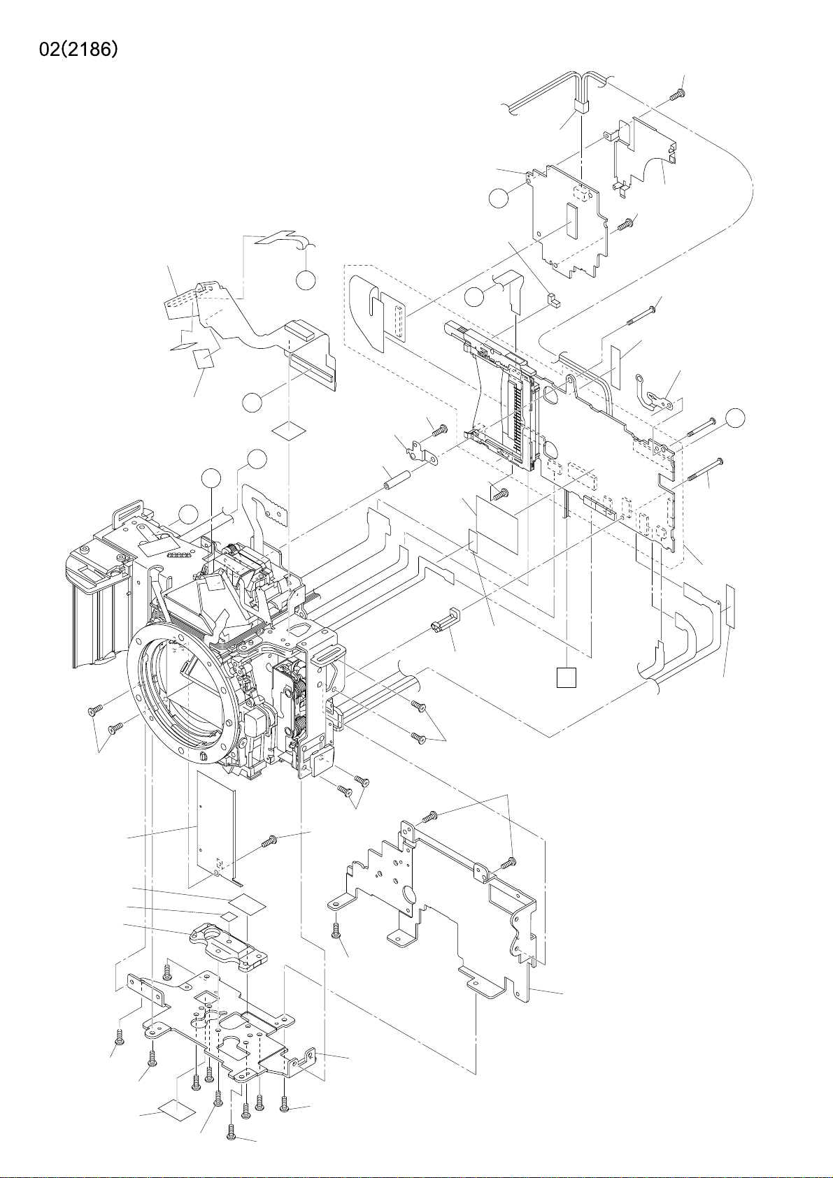
2. Disassembly of the I/O FPC ASSY, MAIN PCB ASSY
Disassemble it in order of step 1to 5.
③③
③
③③
04410441
0441
04410441
■■
Fig. 3Fig. 3
■
Fig. 3
■■
Fig. 3Fig. 3
B
DCDC PCB ASSYDCDC PCB ASSY
DCDC PCB ASSY
DCDC PCB ASSYDCDC PCB ASSY
■■
Fig. 6, 7Fig. 6, 7
■
Fig. 6, 7
■■
Fig. 6, 7Fig. 6, 7
9747-1740-019747-1740-01
9747-1740-01
9747-1740-019747-1740-01
10211021
1021
10211021
9747-1740-019747-1740-01
9747-1740-01
9747-1740-019747-1740-01
I/O FPC ASSYI/O FPC ASSY
I/O FPC ASSY
I/O FPC ASSYI/O FPC ASSY
9384-2191-00(2)9384-2191-00(2)
9384-2191-00(2)
9384-2191-00(2)9384-2191-00(2)
(10x10mm)(10x10mm)
(10x10mm)
(10x10mm)(10x10mm)
■■
Fig. 2Fig. 2
■
Fig. 2
■■
Fig. 2Fig. 2
REPAIR GUIDE
See Page 11.See Page 11.
See Page 11.
See Page 11.See Page 11.
9745-2025-01(2)9745-2025-01(2)
9745-2025-01(2)
9745-2025-01(2)9745-2025-01(2)
■■
■
■■
Fig. 1Fig. 1
Fig. 1
Fig. 1Fig. 1
②②
②
②②
9384-2191-009384-2191-00
9384-2191-00
9384-2191-009384-2191-00
(10x10mm)(10x10mm)
(10x10mm)
(10x10mm)(10x10mm)
■■
Fig. 2Fig. 2
■
Fig. 2
■■
Fig. 2Fig. 2
B
D
A
MAIN PCB ASSYMAIN PCB ASSY
MAIN PCB ASSY
C
A
D
MAIN PCB ASSYMAIN PCB ASSY
9744-1615-019744-1615-01
9744-1615-01
9744-1615-019744-1615-01
27082708
2708
27082708
■■
Fig. 11Fig. 11
■
Fig. 11
■■
Fig. 11Fig. 11
11731173
1173
11731173
■■
Fig. 12Fig. 12
■
Fig. 12
■■
Fig. 12Fig. 12
9749-9749-
1735-151735-15
9749-
1735-15
9749-9749-
1735-151735-15
45144514
4514
45144514
■■
Fig. 8Fig. 8
■
Fig. 8
■■
Fig. 8Fig. 8
11721172
1172
11721172
■■
■
■■
9745-2025-01(2)9745-2025-01(2)
9745-2025-01(2)
9745-2025-01(2)9745-2025-01(2)
9384-2290-909384-2290-90
9384-2290-90
9384-2290-909384-2290-90
(5x10mm)(5x10mm)
(5x10mm)
(5x10mm)(5x10mm)
Fig. 10Fig. 10
Fig. 10
Fig. 10Fig. 10
See Page 4.See Page 4.
See Page 4.
See Page 4.See Page 4.
45204520
4520
45204520
■■
■
■■
A
Fig. 4Fig. 4
Fig. 4
Fig. 4Fig. 4
11751175
1175
11751175
9384-2290-909384-2290-90
9384-2290-90
9384-2290-909384-2290-90
(5x20mm)(5x20mm)
(5x20mm)
(5x20mm)(5x20mm)
■■
Fig. 5Fig. 5
■
Fig. 5
■■
Fig. 5Fig. 5
27092709
2709
27092709
■■
Fig. 9Fig. 9
■
Fig. 9
■■
Fig. 9Fig. 9
11751175
1175
11751175
9384-2290-909384-2290-90
9384-2290-90
9384-2290-909384-2290-90
(5x20mm)(5x20mm)
(5x20mm)
(5x20mm)(5x20mm)
④④
④
④④
C
11761176
1176
11761176
9745-2025-019745-2025-01
9745-2025-01
9745-2025-019745-2025-01
9748-2045-019748-2045-01
9748-2045-01
9748-2045-019748-2045-01
9746-2030-019746-2030-01
9746-2030-01
9746-2030-019746-2030-01
9746-2025-01(5)9746-2025-01(5)
9746-2025-01(5)
9746-2025-01(5)9746-2025-01(5)
29402940
2940
29402940
10131013
1013
10131013
29402940
2940
29402940
10121012
1012
10121012
9748-9748-
9748-
10781078
1078
10781078
9746-2030-019746-2030-01
9746-2030-01
9746-2030-019746-2030-01
9748-9748-
9747-1740-019747-1740-01
9747-1740-01
9747-1740-019747-1740-01
10041004
1004
10041004
9745-2025-019745-2025-01
9745-2025-01
9745-2025-019745-2025-01
2050-15(2)2050-15(2)
2050-15(2)
2050-15(2)2050-15(2)
9748-2045-019748-2045-01
9748-2045-01
9748-2045-019748-2045-01
⑤⑤
⑤
⑤⑤
9611-2025-01(2)9611-2025-01(2)
9611-2025-01(2)
9611-2025-01(2)9611-2025-01(2)
10011001
1001
10011001
①①
①
①①
Page 38

REPAIR GUIDE
■■
Fig. 1Fig. 1
■
Fig. 1
■■
Fig. 1Fig. 1
I/O FLEXIBLE ASSYI/O FLEXIBLE ASSY
I/O FLEXIBLE ASSY
I/O FLEXIBLE ASSYI/O FLEXIBLE ASSY
■■
Fig. 3Fig. 3
■
Fig. 3
■■
Fig. 3Fig. 3
POWER SUPPLY HARNESSPOWER SUPPLY HARNESS
POWER SUPPLY HARNESS
POWER SUPPLY HARNESSPOWER SUPPLY HARNESS
ConnectorConnector
Connector
ConnectorConnector
■■
■
■■
■■
■
■■
Fig. 2Fig. 2
Fig. 2
Fig. 2Fig. 2
9384-2191-009384-2191-00
9384-2191-00
9384-2191-009384-2191-00
(10x10mm)(10x10mm)
(10x10mm)
(10x10mm)(10x10mm)
Fig. 4Fig. 4
Fig. 4
Fig. 4Fig. 4
(2186) 9
9384-2191-00 (2)9384-2191-00 (2)
9384-2191-00 (2)
9384-2191-00 (2)9384-2191-00 (2)
(10x10mm)(10x10mm)
(10x10mm)
(10x10mm)(10x10mm)
45204520
4520
45204520
■■
Fig. 5Fig. 5
■
Fig. 5
■■
Fig. 5Fig. 5
MAIN PCB ASSYMAIN PCB ASSY
MAIN PCB ASSY
MAIN PCB ASSYMAIN PCB ASSY
ConnectorConnector
Connector
ConnectorConnector
9384-2290-909384-2290-90
9384-2290-90
9384-2290-909384-2290-90
(5x20mm)(5x20mm)
(5x20mm)
(5x20mm)(5x20mm)
POWER SUPPLYPOWER SUPPLY
POWER SUPPLY
POWER SUPPLYPOWER SUPPLY
HARNESSHARNESS
HARNESS
HARNESSHARNESS
MAIN PCB ASSYMAIN PCB ASSY
MAIN PCB ASSY
MAIN PCB ASSYMAIN PCB ASSY
■■
Fig. 6Fig. 6
■
Fig. 6
■■
Fig. 6Fig. 6
DCDC PCB ASSYDCDC PCB ASSY
DCDC PCB ASSY
DCDC PCB ASSYDCDC PCB ASSY
SolderSolder
Solder
SolderSolder
Page 39

10 (2186)
■■
Fig. 7Fig. 7
■
Fig. 7
■■
Fig. 7Fig. 7
DCDC PCB ASSYDCDC PCB ASSY
DCDC PCB ASSY
DCDC PCB ASSYDCDC PCB ASSY
■■
Fig. 9Fig. 9
■
Fig. 9
■■
Fig. 9Fig. 9
ConnectorConnector
Connector
ConnectorConnector
MAIN PCB ASSYMAIN PCB ASSY
MAIN PCB ASSY
MAIN PCB ASSYMAIN PCB ASSY
■■
■
■■
Fig. 8Fig. 8
Fig. 8
Fig. 8Fig. 8
■■
■
■■
Fig. 10Fig. 10
Fig. 10
Fig. 10Fig. 10
MAIN PCB ASSYMAIN PCB ASSY
MAIN PCB ASSY
MAIN PCB ASSYMAIN PCB ASSY
45144514
4514
45144514
REPAIR GUIDE
■■
Fig. 11Fig. 11
■
Fig. 11 ■■
■■
Fig. 11Fig. 11
27092709
2709
27092709
27082708
2708
27082708
■■
■
Fig. 12Fig. 12
Fig. 12
Fig. 12Fig. 12
11721172
1172
11721172
11731173
1173
11731173
Page 40

REPAIR GUIDE
3. Disassembly of the SUB PLATE L, BATTERY CHAMBER
Disassemble it in order of step 1 to 3.
9745-2025-019745-2025-01
9745-2025-01
See Page 23.See Page 23.
See Page 23.
See Page 23.See Page 23.
③③
③
③③
9748-2050-019748-2050-01
9748-2050-01
9748-2050-019748-2050-01
9745-2025-019745-2025-01
9748-2050-019748-2050-01
9748-2050-01
9748-2050-019748-2050-01
9747-1735-019747-1735-01
9747-1735-01
9747-1735-019747-1735-01
50345034
5034
50345034
■■
Fig. 2Fig. 2
■
Fig. 2
■■
Fig. 2Fig. 2
9748-2050-019748-2050-01
9748-2050-01
9748-2050-019748-2050-01
REMOTE FPCREMOTE FPC
REMOTE FPC
REMOTE FPCREMOTE FPC
■■
Fig. 1Fig. 1
■
Fig. 1
■■
Fig. 1Fig. 1
9748-2050-01(2)9748-2050-01(2)
9748-2050-01(2)
9748-2050-01(2)9748-2050-01(2)
SUS PLATE LSUS PLATE L
SUS PLATE L
SUS PLATE LSUS PLATE L
②②
②
②②
10661066
1066
10661066
9744-1625-01(2)9744-1625-01(2)
9744-1625-01(2)
9744-1625-01(2)9744-1625-01(2)
01410141
0141
01410141
(2186) 11
9745-2025-01(2)9745-2025-01(2)
9745-2025-01(2)
9745-2025-01(2)9745-2025-01(2)
10051005
1005
10051005
9611-9611-
9611-
9611-96112025-01(2)2025-01(2)
2025-01(2)
2025-01(2)2025-01(2)
11461146
1146
11461146
9748-2050-019748-2050-01
9748-2050-01
9748-2050-019748-2050-01
■■
Fig. 4Fig. 4
■
Fig. 4
■■
Fig. 4Fig. 4
9747-1735-019747-1735-01
9747-1735-01
9747-1735-019747-1735-01
50335033
5033
50335033
■■
Fig. 3Fig. 3
■
Fig. 3
■■
Fig. 3Fig. 3
①①
①
①①
See Page 13.See Page 13.
See Page 13.
See Page 13.See Page 13.
11441144
1144
11441144
Page 41

12 (2186)
■■
Fig. 1Fig. 1
■
Fig. 1
■■
Fig. 1Fig. 1
FPC of AF CHARGE ASSYFPC of AF CHARGE ASSY
FPC of AF CHARGE ASSY
FPC of AF CHARGE ASSYFPC of AF CHARGE ASSY
REMOTE FPCREMOTE FPC
REMOTE FPC
REMOTE FPCREMOTE FPC
■■
Fig. 2Fig. 2
■
Fig. 2
■■
Fig. 2Fig. 2
FPC of AF MODULE ASSYFPC of AF MODULE ASSY
FPC of AF MODULE ASSY
FPC of AF MODULE ASSYFPC of AF MODULE ASSY
■■
■
■■
Fig. 3Fig. 3
Fig. 3
Fig. 3Fig. 3
FPC of SHUTTER ASSYFPC of SHUTTER ASSY
FPC of SHUTTER ASSY
FPC of SHUTTER ASSYFPC of SHUTTER ASSY
50335033
5033
50335033
REPAIR GUIDE
■■
Fig. 4Fig. 4
■
Fig. 4
■■
Fig. 4Fig. 4
50345034
5034
50345034
9748-2050-019748-2050-01
9748-2050-01
9748-2050-019748-2050-01
SUS PLATE GSUS PLATE G
SUS PLATE G
SUS PLATE GSUS PLATE G
Page 42

(2186) 13
REPAIR GUIDE
4. Disassembly of the CCD ASSY, SHUTTER ASSY
If CCD ASSY (0271) is exchanged for new one, exchange the bar code on the MAIN PCB ASSY (0410) for
the bar code put on the new CCD ASSY.
Disassemble it in order of step 1 to 4.
CCD FPC ASSYCCD FPC ASSY
CCD FPC ASSY
CCD FPC ASSYCCD FPC ASSY
■■
Fig. 1Fig. 1
■
Fig. 1
■■
Fig. 1Fig. 1
2181-27022181-2702
2181-2702
2181-27022181-2702
27212721
2721
27212721
9747-1745-01(4)9747-1745-01(4)
9747-1745-01(4)
9747-1745-01(4)9747-1745-01(4)
CCD ASSYCCD ASSY
CCD ASSY
CCD ASSYCCD ASSY
27152715
2715
27152715
①①
①
①①
9744-16189744-1618
9744-1618
9744-16189744-1618
9748-2055-019748-2055-01
9748-2055-01
9748-2055-019748-2055-01
A
B
9748-2055-01(2)9748-2055-01(2)
9748-2055-01(2)
9748-2055-01(2)9748-2055-01(2)
2181-29202181-2920
2181-2920
2181-29202181-2920
■■
Fig. 5Fig. 5
■
Fig. 5
■■
Fig. 5Fig. 5
2181-29182181-2918
2181-2918
2181-29182181-2918
9758-0100-009758-0100-00
9758-0100-00
29612961
2961
29612961
■■
■
■■
SLIDER ASSYSLIDER ASSY
SLIDER ASSY
SLIDER ASSYSLIDER ASSY
9758-0100-009758-0100-00
Fig. 2Fig. 2
Fig. 2
Fig. 2Fig. 2
9744-1620-019744-1620-01
9744-1620-01
9744-1620-019744-1620-01
9384-2190-509384-2190-50
9384-2190-50
9384-2190-509384-2190-50
(3.5x10mm)(3.5x10mm)
(3.5x10mm)
(3.5x10mm)(3.5x10mm)
■■
Fig. 4Fig. 4
■
Fig. 4
■■
Fig. 4Fig. 4
②②
②
②②
2181-2706(3)*12181-2706(3)*1
2181-2706(3)*1
2181-2706(3)*12181-2706(3)*1
A
C
9747-1775-019747-1775-01
9747-1775-01
9747-1775-019747-1775-01
B
MAIN PLATE ASSYMAIN PLATE ASSY
MAIN PLATE ASSY
MAIN PLATE ASSYMAIN PLATE ASSY
2722(3)2722(3)
2722(3)
2722(3)2722(3)
2703(3)2703(3)
2703(3)
2703(3)2703(3)
9744-1635-019744-1635-01
9744-1635-01
9744-1635-019744-1635-01
*1:*1:
*1:
*1:*1:
9796-2040-40(3)9796-2040-40(3)
9796-2040-40(3)
9796-2040-40(3)9796-2040-40(3)
C
③③
③
③③
BB
B
B-50B-50
BB
B-50
B-50B-50
(After completing the Adjustment of(After completing the Adjustment of
(After completing the Adjustment of
(After completing the Adjustment of(After completing the Adjustment of
CCD position and perspective (pg.41))CCD position and perspective (pg.41))
CCD position and perspective (pg.41))
CCD position and perspective (pg.41))CCD position and perspective (pg.41))
SHUTTER ASSYSHUTTER ASSY
SHUTTER ASSY
SHUTTER ASSYSHUTTER ASSY
9744-1630-019744-1630-01
9744-1630-01
9744-1630-019744-1630-01
11711171
1171
11711171
■■
Fig. 1Fig. 1
■
Fig. 1
■■
Fig. 1Fig. 1
See Page 17.See Page 17.
See Page 17.
See Page 17.See Page 17.
2181-51332181-5133
2181-5133
2181-51332181-5133
④④
④
④④
See Shutter AssySee Shutter Assy
See Shutter Assy
See Shutter AssySee Shutter Assy
Installation (pg. 15)Installation (pg. 15)
Installation (pg. 15)
Installation (pg. 15)Installation (pg. 15)
Page 43

14 (2186)
■■
Fig. 1Fig. 1
■
Fig. 1
■■
Fig. 1Fig. 1
11711171
1171
11711171
■■
Fig. 3Fig. 3
■
Fig. 3
■■
Fig. 3Fig. 3
27212721
2721
27212721
■■
■
■■
Fig. 2Fig. 2
Fig. 2
Fig. 2Fig. 2
■■
Fig. 4Fig. 4
■
Fig. 4
■■
Fig. 4Fig. 4
29612961
2961
29612961
REPAIR GUIDE
■■
Fig. 5Fig. 5
■
Fig. 5
■■
Fig. 5Fig. 5
SLIDER ASSYSLIDER ASSY
SLIDER ASSY
SLIDER ASSYSLIDER ASSY
Flexible of CCD ASSYFlexible of CCD ASSY
Flexible of CCD ASSY
Flexible of CCD ASSYFlexible of CCD ASSY
2181-29182181-2918
2181-2918
2181-29182181-2918
29372937
2937
29372937
CCD CONECTING FPCCCD CONECTING FPC
CCD CONECTING FPC
CCD CONECTING FPCCCD CONECTING FPC
2181-29202181-2920
2181-2920
2181-29202181-2920
Page 44

(2186) 15
REPAIR GUIDE
SHUTTER ASSY Installation
1. Supply power to the charge motor at 2V/1A to drive it normally until the mirror raises completely.
DC Power SupplyDC Power Supply
DC Power Supply
DC Power SupplyDC Power Supply
(2V, 1A)(2V, 1A)
(2V, 1A)
(2V, 1A)(2V, 1A)
++
+
−−
++
−
−−
2. Insert screw driver into the hole of SHUTTER CHARGE GEAR, and put SHUTTER ASSY
by holding the screw driver at the 90 degrees position shown on the picture.
DriverDriver
Driver
DriverDriver
SHUTTER CHARGE GEARSHUTTER CHARGE GEAR
SHUTTER CHARGE GEAR
SHUTTER CHARGE GEARSHUTTER CHARGE GEAR
Page 45

16 (2186)
■■
■CCD inclination adjustment / repair
■■
Check
Setup the equipments so that the camera faces to a subject at accurate level;
1. Use a copy stand or place a mirror on the wall.
2. Use a 50/1.7 lens for inspection.
3. Measure an angle of gradient by Photoshop.
If it is beyond +/- 1.0 degree, be sure to implement the Repair method (mentioned later).
If it is between +/- 0.5 and +/- 1.0 degree, implement the Repair method (mentioned later) upon
request of the user.
If it is within +/- 0.5 degree, implement the Inspection again to correct measurement error.
Adjustment
1. Remove the CCD SLANTING STOPPER. (Fig. 1)
2. Check and adjust of a hexagon eccentric pin. (Fig. 2)
* 60-degree (0.42 degree of CCD inclination) rotation is possible respectively from a neutral position to
a clock and a counterclockwise direction.
The adjustment over 60 degrees is impossible. (CCD SLANTING STOPPER cannot be attached.)
Rotate 60 degrees clockwise, when the image slants to the right.
Rotate 60 degrees counterclockwise, when the image slants to the left.
■■
Fig. 1Fig. 1
■
Fig. 1
■■
Fig. 1Fig. 1
■■
■
■■
Fig. 2Fig. 2
Fig. 2
Fig. 2Fig. 2
REPAIR GUIDE
Repair (when it cannot be adjusted by the above adjustment method)
1. Disassemble the body so that the CCD Assy can be removed.
2. Cut the two posts (fig. 3); one for positioning and the other for direction standard between the CCD
holder (in the Slider Assy) and the heat sink plate (in the CCD Assy).
3. Install an insulation sheet on the terminal of the CCD Assy or on the contact surface of the CCD holder.
(to prevent short-circuit between the CCD terminal and CCD holder)
4. Adjust the position of the CCD Assy and then assemble it.
When an image tilts to the right, turn it clockwise.
When an image tilts to the left, turn it counterclockwise.
The tilt can be corrected approx. +/- 0.7 degree at the max. by shifting double faced tape on the LPF*.
*Prepare a spare parts of Tebure Assy with the above mentioned step 2 applied separately and shift the
position by using it. Donot shift the tape on the users Tebure Assy to prevent the Tebure Assy from
being broken.
5. Assemble the whole unit.
6. Implement the Inspection.
If the variance is beyond +/- 0.5 degree, replace the Tebure Assy. Implement the Inspection again.
7. Perform adjustment of CCD AORI & CENTER, camera shaking compensation after the completion of
repair.
CCD SLANTING STOPPERCCD SLANTING STOPPER
CCD SLANTING STOPPER
CCD SLANTING STOPPERCCD SLANTING STOPPER
■■
Fig. 3Fig. 3
■
Fig. 3
■■
Fig. 3Fig. 3
(Neutral position)(Neutral position)
(Neutral position)
(Neutral position)(Neutral position)
Page 46

REPAIR GUIDE
5. Disassembly-1 of the MIRROR BOX ASSY
(2186) 17
Disassemble it in order of step 1 to 6.
9747-1745-01(3)9747-1745-01(3)
9747-1745-01(3)
9747-1745-01(3)9747-1745-01(3)
9384-2290-909384-2290-90
9384-2290-90
9384-2290-909384-2290-90
(9x15mm)(9x15mm)
(9x15mm)
(9x15mm)(9x15mm)
■■
Fig. 1Fig. 1
■
Fig. 1
■■
Fig. 1Fig. 1
PENTA ASSYPENTA ASSY
PENTA ASSY
PENTA ASSYPENTA ASSY
INF LCD HOLDER ASSYINF LCD HOLDER ASSY
INF LCD HOLDER ASSY
INF LCD HOLDER ASSYINF LCD HOLDER ASSY
50485048
5048
50485048
②②
②
②②
■■
Fig. 1Fig. 1
■
Fig. 1
■■
Fig. 1Fig. 1
①①
①
①①
TOUKO ASSYTOUKO ASSY
TOUKO ASSY
TOUKO ASSYTOUKO ASSY
9747-1745-01(2)9747-1745-01(2)
9747-1745-01(2)
9747-1745-01(2)9747-1745-01(2)
9747-9747-
9747-
9747-9747-
1735-01(2)1735-01(2)
1735-01(2)
1735-01(2)1735-01(2)
⑥⑥
⑥
⑥⑥
50225022
5022
50225022
■■
■
■■
④④
④
④④
DIOPTER ASSYDIOPTER ASSY
DIOPTER ASSY
DIOPTER ASSYDIOPTER ASSY
⑤⑤
⑤
⑤⑤
③③
③
③③
Fig. 2Fig. 2
Fig. 2
Fig. 2Fig. 2
9747-1745-01(2)9747-1745-01(2)
9747-1745-01(2)
9747-1745-01(2)9747-1745-01(2)
FRESNELFRESNEL
FRESNEL
FRESNELFRESNEL
2181-50162181-5016
2181-5016
2181-50162181-5016
SI SCREENSI SCREEN
SI SCREEN
SI SCREENSI SCREEN
VB WASHERVB WASHER
VB WASHER
VB WASHERVB WASHER
Hook the tip of #2181-5016 to theHook the tip of #2181-5016 to the
Hook the tip of #2181-5016 to the
Hook the tip of #2181-5016 to theHook the tip of #2181-5016 to the
notch of PENTA ASSYnotch of PENTA ASSY
notch of PENTA ASSY
notch of PENTA ASSYnotch of PENTA ASSY
See Page 19.See Page 19.
See Page 19.
See Page 19.See Page 19.
2162-2659(3)2162-2659(3)
2162-2659(3)
9384-2190-509384-2190-50
9384-2190-50
9384-2190-509384-2190-50
(3x5mm)(3x5mm)
(3x5mm)
(3x5mm)(3x5mm)
■■
Fig. 3Fig. 3
■
Fig. 3
■■
Fig. 3Fig. 3
AF MODULE ASSYAF MODULE ASSY
AF MODULE ASSY
AF MODULE ASSYAF MODULE ASSY
(After completing the Pitch,Yaw adjustment (pg.47)(After completing the Pitch,Yaw adjustment (pg.47)
(After completing the Pitch,Yaw adjustment (pg.47)
(After completing the Pitch,Yaw adjustment (pg.47)(After completing the Pitch,Yaw adjustment (pg.47)
2162-2659(3)2162-2659(3)
2082-5054(3)2082-5054(3)
2082-5054(3)
2082-5054(3)2082-5054(3)
2162-2658(3)2162-2658(3)
2162-2658(3)
2162-2658(3)2162-2658(3)
BB
B
BB
B-50B-50
B-50
B-50B-50
Page 47

18 (2186)
■■
Fig. 1Fig. 1
■
Fig. 1
■■
Fig. 1Fig. 1
■■
Fig. 3Fig. 3
■
Fig. 3
■■
Fig. 3Fig. 3
REPAIR GUIDE
50485048
5048
50485048
9384-2290-909384-2290-90
9384-2290-90
9384-2290-909384-2290-90
(9x15mm)(9x15mm)
(9x15mm)
(9x15mm)(9x15mm)
■■
■
■■
Fig. 2Fig. 2
Fig. 2
Fig. 2Fig. 2
50225022
5022
50225022
9384-2190-509384-2190-50
9384-2190-50
9384-2190-509384-2190-50
(3x5mm)(3x5mm)
(3x5mm)
(3x5mm)(3x5mm)
AF MODULE ASSYAF MODULE ASSY
AF MODULE ASSY
AF MODULE ASSYAF MODULE ASSY
Page 48

REPAIR GUIDE
6. Disassembly-2 of the MIRROR BOX ASSY
Disassemble it in order of step 1 to 5.
9747-1750-019747-1750-01
9747-1750-01
9747-1750-019747-1750-01
APERTURE ASSYAPERTURE ASSY
APERTURE ASSY
APERTURE ASSYAPERTURE ASSY
See APERTURE ASSY Setting (pg. 21)See APERTURE ASSY Setting (pg. 21)
See APERTURE ASSY Setting (pg. 21)
See APERTURE ASSY Setting (pg. 21)See APERTURE ASSY Setting (pg. 21)
⑤⑤
⑤
⑤⑤
25122512
2512
25122512
25332533
2533
25332533
9747-1750-01(2)9747-1750-01(2)
9747-1750-01(2)
9747-1750-01(2)9747-1750-01(2)
25332533
2533
25332533
25322532
2532
25322532
(2186) 19
See Page 22.See Page 22.
See Page 22.
See Page 22.See Page 22.
APERTURE RINGAPERTURE RING
APERTURE RING
APERTURE RINGAPERTURE RING
See APERTURE RINGSee APERTURE RING
See APERTURE RING
See APERTURE RINGSee APERTURE RING
Removal/Installation (pg. 21)Removal/Installation (pg. 21)
Removal/Installation (pg. 21)
Removal/Installation (pg. 21)Removal/Installation (pg. 21)
15241524
1524
15241524
2163-15212163-1521
2163-1521
2163-15212163-1521
9761-2055-04(6)9761-2055-04(6)
9761-2055-04(6)
9761-2055-04(6)9761-2055-04(6)
15111511
1511
15111511
2181-51232181-5123
2181-5123
②②
②
②②
AF CHARGE ASSYAF CHARGE ASSY
AF CHARGE ASSY
AF CHARGE ASSYAF CHARGE ASSY
See AF CHARGE ASSYSee AF CHARGE ASSY
See AF CHARGE ASSY
See AF CHARGE ASSYSee AF CHARGE ASSY
Installation (pg. 20)Installation (pg. 20)
Installation (pg. 20)
Installation (pg. 20)Installation (pg. 20)
2181-51232181-5123
2181-15152181-1515
2181-1515
2181-15152181-1515
GG
G-85G-85
G
G-85
GG
G-85G-85
(Both surfaces)(Both surfaces)
(Both surfaces)
(Both surfaces)(Both surfaces)
④④
④
④④
25352535
2535
25352535
25342534
2534
25342534
9747-1745-019747-1745-01
9747-1745-01
9747-1745-019747-1745-01
①①
①
①①
15451545
1545
15451545
18131813
1813
18131813
25322532
2532
25322532
2181-51232181-5123
2181-5123
2181-51232181-5123
2162-15472162-1547
2162-1547
2162-15472162-1547
15251525
1525
15251525
15211521
1521
15211521
9749-1730-019749-1730-01
9749-1730-01
9749-1730-019749-1730-01
15231523
1523
15231523
■■
Fig. 1, 2Fig. 1, 2
■
Fig. 1, 2
■■
Fig. 1, 2Fig. 1, 2
③③
③
③③
15201520
1520
15201520
■■
Fig. 1Fig. 1
■
Fig. 1
■■
Fig. 1Fig. 1
15221522
1522
15221522
05260526
0526
05260526
9747-1745-019747-1745-01
9747-1745-01
9747-1745-019747-1745-01
Page 49

20 (2186)
■■
Fig. 2Fig. 2
■
Fig. 2
■■
■■
■
■■
Fig. 1Fig. 1
Fig. 1
Fig. 1Fig. 1
COUPLER LEVERCOUPLER LEVER
COUPLER LEVER
COUPLER LEVERCOUPLER LEVER
Fig. 2Fig. 2
COUPLER LEVER SPCOUPLER LEVER SP
COUPLER LEVER SP
COUPLER LEVER SPCOUPLER LEVER SP
AF CHARGE ASSY Installation
1. Rotate the designated cam-gear in arrow direction while keep pushing the lever against it until the
lever descends down to the lowest.
2. Arrange the wires.
REPAIR GUIDE
LeverLever
Lever
LeverLever
Cam-gearCam-gear
Cam-gear
Cam-gearCam-gear
Page 50

(2186) 21
REPAIR GUIDE
APERTURE RING Removal/Installation
Removal
Turn APERTURE RING clockwise until it stops (Fig. 4). Now the ring can be removed.
Be careful not to turn the aperture coupling gear in APERTURE ASSY.
Installation
1. Set APERTURE ASSY to the charge completion position (default position) referring APERTURE ASSY
setting procedure as shown below, then install to FRONT FRAME ASSY.
APERTURE ASSY is at the charge completion position if it has never been removed, or the aperture
coupling gear has not been turned after removing APERTURE RING.
2. Install APERTURE RING so that the punch mark is positioned as illustrated. (Fig. 4)
■■
Fig. 4Fig. 4
■
Fig. 4
■■
Fig. 4Fig. 4
APERTURE RINGAPERTURE RING
APERTURE RING
APERTURE RINGAPERTURE RING
Punch markPunch mark
Punch mark
Punch markPunch mark
APERTURE ASSY Setting
Firstly confirm APERTURE ASSY is at the charge position (default position).
When the charge position was changed by APERTURE ASSY removal.
1. Reset Position Check
1-1. Confirm on which side (a or b in Fig. 5) in the square opening (of APERTURE ASSY) the
spring leg lies.
1-2. Turn the APERTURE REDUCTION GEAR in the direction opposite to the spring location (a or
b in Fig. 2) until the spring leg moves over to the other side.
e.g. IF the spring lies at a in Fig. 5, turn the gear toward a in Fig. 5.
1-3. With the above condition, turn the APERTURE REDUCTION GEAR slightly until its through hole
aligns with the through hole of the APERTURE BASEPLATE-A (Fig. 3).
2. Charge position setting.
2-1. Make sure that APERTURE ASSY is set to the reset position.
View from the front of APERTURE ASSY.
Turn APERTURE REDUCTION GEAR to clockwise direction 3 times until its through hole aligns
with the through hole of APERTURE BASEPLATE-A
APERTURE REDUCTION GEAR is set to charge position (default position). (Fig. 5)
■■
Fig. 5Fig. 5
■
Fig. 5
■■
Fig. 5Fig. 5
bb
b
bb
aa
a
aa
Aperture baseplate-AAperture baseplate-A
Aperture baseplate-A
Aperture baseplate-AAperture baseplate-A
Spring legSpring leg
Spring leg
Spring legSpring leg
bb
b
bb
Aperture reduction gearAperture reduction gear
Aperture reduction gear
Aperture reduction gearAperture reduction gear
絞り減速ギヤ絞り減速ギヤ
絞り減速ギヤ
絞り減速ギヤ絞り減速ギヤ
ApertureAperture
Aperture
aa
a
aa
ApertureAperture
reduction gearreduction gear
reduction gear
reduction gearreduction gear
Page 51

22 (2186)
7. Disassembly-3 of the MIRROR BOX ASSY
Disassemble it in order of step 1 to 4.
9769-1740-019769-1740-01
9769-1740-01
9769-1740-019769-1740-01
REPAIR GUIDE
BL CONTACTBL CONTACT
BL CONTACT
BL CONTACTBL CONTACT
HOLDER ASSYHOLDER ASSY
HOLDER ASSY
HOLDER ASSYHOLDER ASSY
9769-1740-019769-1740-01
9769-1740-01
9769-1740-019769-1740-01
51095109
5109
51095109
■■
■
■■
18121812
1812
18121812
Fig. 1Fig. 1
Fig. 1
Fig. 1Fig. 1
05150515
0515
05150515
■■
■
■■
Fig. 6Fig. 6
Fig. 6
Fig. 6Fig. 6
④④
④
④④
5110(2)5110(2)
5110(2)
5110(2)5110(2)
9769-1730-01(2)9769-1730-01(2)
9769-1730-01(2)
9769-1730-01(2)9769-1730-01(2)
05140514
0514
05140514
■■
Fig. 5Fig. 5
■
Fig. 5
■■
Fig. 5Fig. 5
③③
③
③③
58065806
5806
58065806
B-50B-50
BB
B-50
B B-50B-50
BB
(After installation, allow(After installation, allow
(After installation, allow
(After installation, allow(After installation, allow
to dry for 8 - 12 hours.) to dry for 8 - 12 hours.)
to dry for 8 - 12 hours.)
to dry for 8 - 12 hours.) to dry for 8 - 12 hours.)
FRONT FRAME ASSYFRONT FRAME ASSY
FRONT FRAME ASSY
FRONT FRAME ASSYFRONT FRAME ASSY
51515151
5151
51515151
9747-1745-01(2)9747-1745-01(2)
9747-1745-01(2)
9747-1745-01(2)9747-1745-01(2)
9747-1440-019747-1440-01
9747-1440-01
9747-1440-019747-1440-01
15421542
1542
15421542
15441544
1544
15441544
15431543
1543
15431543
①①
①
①①
51015101
5101
51015101
15481548
1548
15481548
2181-51082181-5108
2181-5108
2181-51082181-5108
51025102
5102
51025102
②②
②
②②
■■
■
51075107
5107
51075107
51125112
5112
51125112
2186-5112-01(4)2186-5112-01(4)
2186-5112-01(4)
2186-5112-01(4)2186-5112-01(4)
■■
Fig. 2 - 4Fig. 2 - 4
Fig. 2 - 4
Fig. 2 - 4Fig. 2 - 4
Page 52

REPAIR GUIDE
■■
■
■■
■■
■
■■
Fig. 1Fig. 1
Fig. 1
Fig. 1Fig. 1
51095109
5109
51095109
Fig. 3Fig. 3
Fig. 3
Fig. 3Fig. 3
51085108
5108
51085108
■■
■
■■
■■
■
■■
Fig. 2Fig. 2
Fig. 2
Fig. 2Fig. 2
Fig. 4Fig. 4
Fig. 4
Fig. 4Fig. 4
(2186) 23
51085108
5108
51085108
MAIN MIRROR DRIVING LEVERMAIN MIRROR DRIVING LEVER
MAIN MIRROR DRIVING LEVER
MAIN MIRROR DRIVING LEVERMAIN MIRROR DRIVING LEVER
■■
■
■■
Fig. 5Fig. 5
Fig. 5
Fig. 5Fig. 5
MIRROR DRIVING LEVERMIRROR DRIVING LEVER
MIRROR DRIVING LEVER
MIRROR DRIVING LEVERMIRROR DRIVING LEVER
MAIN MIRROR HOLDER ASSYMAIN MIRROR HOLDER ASSY
MAIN MIRROR HOLDER ASSY
MAIN MIRROR HOLDER ASSYMAIN MIRROR HOLDER ASSY
MIRROR DRIVING LEVERMIRROR DRIVING LEVER
MIRROR DRIVING LEVER
MIRROR DRIVING LEVERMIRROR DRIVING LEVER
■■
Fig. 6Fig. 6
■
Fig. 6
■■
Fig. 6Fig. 6
51075107
5107
51075107
SUB MIRROR HOLDER ASSYSUB MIRROR HOLDER ASSY
SUB MIRROR HOLDER ASSY
SUB MIRROR HOLDER ASSYSUB MIRROR HOLDER ASSY
SUB MIRROR HOLDER ASSYSUB MIRROR HOLDER ASSY
SUB MIRROR HOLDER ASSY
SUB MIRROR HOLDER ASSYSUB MIRROR HOLDER ASSY
Page 53

24 (2186)
8. Disassembly of the BATTERY CHAMBER, LCD 101
Disassemble it in order of step 1 to 4.
CF CARD COVERCF CARD COVER
CF CARD COVER
CF CARD COVERCF CARD COVER
REPAIR GUIDE
9769-1730-019769-1730-01
9769-1730-01
9769-1730-019769-1730-01
11531153
1153
11531153
11561156
1156
11561156
9747-1735-019747-1735-01
9747-1735-01
9747-1735-019747-1735-01
9747-1735-019747-1735-01
9747-1735-01
9747-1735-019747-1735-01
11591159
1159
11591159
■■
■
■■
01540154
0154
01540154
01550155
0155
01550155
Fig. 3Fig. 3
Fig. 3
Fig. 3Fig. 3
10651065
1065
10651065
①①
①
①①
9761-2055-019761-2055-01
9761-2055-01
9761-2055-019761-2055-01
10881088
1088
10881088
■■
Fig. 4Fig. 4
■
Fig. 4
■■
Fig. 4Fig. 4
9747-1740-019747-1740-01
9747-1740-01
9747-1740-019747-1740-01
9384-2290-909384-2290-90
9384-2290-90
9384-2290-909384-2290-90
(9x15mm)(9x15mm)
(9x15mm)
(9x15mm)(9x15mm)
■■
Fig. 4Fig. 4
■
Fig. 4
■■
Fig. 4Fig. 4
9749-2035-01(2)9749-2035-01(2)
9749-2035-01(2)
9749-2035-01(2)9749-2035-01(2)
10021002
1002
10021002
①①
①
①①
9384-2191-009384-2191-00
9384-2191-00
9384-2191-009384-2191-00
(6x20mm)(6x20mm)
(6x20mm)
(6x20mm)(6x20mm)
GYROGYRO
GYRO
GYROGYRO
FPC ASSYFPC ASSY
FPC ASSY
FPC ASSYFPC ASSY
■■
Fig. 5, 6Fig. 5, 6
■
Fig. 5, 6
■■
Fig. 5, 6Fig. 5, 6
45084508
4508
45084508
10871087
1087
10871087
■■
Fig. 7Fig. 7
■
Fig. 7
■■
Fig. 7Fig. 7
1082(2)1082(2)
1082(2)
1082(2)1082(2)
■■
Fig. 7Fig. 7
■
Fig. 7
■■
Fig. 7Fig. 7
9747-1730-01(2)9747-1730-01(2)
9747-1730-01(2)
9747-1730-01(2)9747-1730-01(2)
BATTERY CHAMBERBATTERY CHAMBER
BATTERY CHAMBER
BATTERY CHAMBERBATTERY CHAMBER
10721072
1072
10721072
10831083
1083
10831083
■■
Fig. 1, 2Fig. 1, 2
■
Fig. 1, 2
■■
Fig. 1, 2Fig. 1, 2
10811081
1081
10811081
■■
Fig. 1Fig. 1
■
Fig. 1
■■
Fig. 1Fig. 1
9749-1735-159749-1735-15
9749-1735-15
9749-1735-159749-1735-15
④④
④
④④
10731073
1073
10731073
■■
■
■■
③③
③
③③
Fig. 7Fig. 7
Fig. 7
Fig. 7Fig. 7
10401040
1040
10401040
04270427
0427
04270427
9747-1740-01(2)9747-1740-01(2)
9747-1740-01(2)
9747-1740-01(2)9747-1740-01(2)
10421042
1042
10421042
9747-1740-019747-1740-01
9747-1740-01
9747-1740-019747-1740-01
10861086
1086
10861086
9747-1750-019747-1750-01
9747-1750-01
9747-1750-019747-1750-01
FLASH PCB ASSYFLASH PCB ASSY
FLASH PCB ASSY
FLASH PCB ASSYFLASH PCB ASSY
②②
②
②②
9747-1740-019747-1740-01
9747-1740-01
9747-1740-019747-1740-01
10411041
1041
10411041
LCD 101LCD 101
LCD 101
LCD 101LCD 101
9384-2190-50(3)9384-2190-50(3)
9384-2190-50(3)
9384-2190-50(3)9384-2190-50(3)
(5x5mm)(5x5mm)
(5x5mm)
(5x5mm)(5x5mm)
■■
Fig. 8Fig. 8
■
Fig. 8
■■
Fig. 8Fig. 8
SW FPC-2 ASSYSW FPC-2 ASSY
SW FPC-2 ASSY
SW FPC-2 ASSYSW FPC-2 ASSY
■■
Fig. 8Fig. 8
■
Fig. 8
■■
Fig. 8Fig. 8
Page 54

REPAIR GUIDE
■■
■
■■
■■
■
■■
Fig. 1Fig. 1
Fig. 1
Fig. 1Fig. 1
Fig. 3Fig. 3
Fig. 3
Fig. 3Fig. 3
10811081
1081
10811081
10831083
1083
10831083
■■
■
■■
■■
■
■■
Fig. 2Fig. 2
Fig. 2
Fig. 2Fig. 2
Fig. 4Fig. 4
Fig. 4
Fig. 4Fig. 4
(2186) 25
10831083
1083
10831083
■■
■
■■
Fig. 5Fig. 5
Fig. 5
Fig. 5Fig. 5
11591159
1159
11591159
GYRO FLEXIBLE ASSYGYRO FLEXIBLE ASSY
GYRO FLEXIBLE ASSY
GYRO FLEXIBLE ASSYGYRO FLEXIBLE ASSY
10881088
1088
10881088
9384-2290-909384-2290-90
9384-2290-90
9384-2290-909384-2290-90
(9x15mm)(9x15mm)
(9x15mm)
(9x15mm)(9x15mm)
10871087
1087
10871087
FLASH PCB ASSYFLASH PCB ASSY
FLASH PCB ASSY
FLASH PCB ASSYFLASH PCB ASSY
Page 55

26 (2186)
■■
Fig. 6Fig. 6
■
Fig. 6
■■
Fig. 6Fig. 6
■■
Fig. 7Fig. 7
■
Fig. 7
■■
Fig. 7Fig. 7
10021002
1002
10021002
GYRO FLEXIBLE ASSYGYRO FLEXIBLE ASSY
GYRO FLEXIBLE ASSY
GYRO FLEXIBLE ASSYGYRO FLEXIBLE ASSY
REPAIR GUIDE
■■
■
■■
Fig. 8Fig. 8
Fig. 8
Fig. 8Fig. 8
10871087
1087
10871087
10401040
1040
10401040
10731073
1073
10731073
SW FPC2 ASSYSW FPC2 ASSY
SW FPC2 ASSY
SW FPC2 ASSYSW FPC2 ASSY
9384-2190-50(3)9384-2190-50(3)
9384-2190-50(3)
9384-2190-50(3)9384-2190-50(3)
(5x5mm)(5x5mm)
(5x5mm)
(5x5mm)(5x5mm)
Page 56

REPAIR GUIDE
9. Disassembly of the TOP COVER ASSY
Disassemble it in order of step 1 to 11. (Continued to the next page)
9747-1745-04(2)(-650)9747-1745-04(2)(-650)
9747-1745-04(2)(-650)
9747-1745-04(2)(-650)9747-1745-04(2)(-650)
9747-1745-15(2)(-090,-100,-300,-600)9747-1745-15(2)(-090,-100,-300,-600)
9747-1745-15(2)(-090,-100,-300,-600)
9747-1745-15(2)(-090,-100,-300,-600)9747-1745-15(2)(-090,-100,-300,-600)
MODE DIAL NAME PLATEMODE DIAL NAME PLATE
MODE DIAL NAME PLATE
MODE DIAL NAME PLATEMODE DIAL NAME PLATE
14771477
1477
14771477
MODE DIALMODE DIAL
MODE DIAL
MODE DIALMODE DIAL
01660166
0166
01660166
■■
Fig. 4Fig. 4
■
Fig. 4
■■
MODE DIALMODE DIAL
MODE DIAL
MODE DIALMODE DIAL
DECORATION RINGDECORATION RING
DECORATION RING
DECORATION RINGDECORATION RING
14021402
1402
14021402
14241424
1424
14241424
16031603
1603
16031603
■■
Fig. 4Fig. 4
■
Fig. 4
■■
Fig. 4Fig. 4
16021602
1602
16021602
⑪⑪
⑪
⑪⑪
9747-1745-15(2)9747-1745-15(2)
9747-1745-15(2)
9747-1745-15(2)9747-1745-15(2)
BB
B
B-20B-20
BB
B-20
B-20B-20
Fig. 4Fig. 4
⑥⑥
⑥
⑥⑥
2089-16072089-1607
2089-1607
2089-16072089-1607
⑩⑩
⑩
⑩⑩
2089-16202089-1620
2089-1620
2089-16202089-1620
⑧⑧
⑧
⑧⑧
(2186) 27
FLASH CASE (UPPER)FLASH CASE (UPPER)
FLASH CASE (UPPER)
FLASH CASE (UPPER)FLASH CASE (UPPER)
⑤⑤
⑤
⑤⑤
⑦⑦
⑦
⑦⑦
16091609
1609
16091609
■■
Fig. 5Fig. 5
■
Fig. 5
■■
Fig. 5Fig. 5
16131613
1613
16131613
WBWB
WB
WBWB
BUTTONBUTTON
BUTTON
⑨⑨
⑨
⑨⑨
2089-16212089-1621
2089-1621
2089-16212089-1621
WB DIALWB DIAL
WB DIAL
WB DIALWB DIAL
NAME PLATENAME PLATE
NAME PLATE
NAME PLATENAME PLATE
BUTTONBUTTON
14771477
1477
14771477
9721-0120-509721-0120-50
9721-0120-50
9721-0120-509721-0120-50
2181-13052181-1305
2181-1305
2181-13052181-1305
14041404
1404
14041404
BB
B-110B-110
B
B-110
BB
B-110B-110
2162-1477(2)2162-1477(2)
2162-1477(2)
2162-1477(2)2162-1477(2)
9758-0150-00(2)9758-0150-00(2)
9758-0150-00(2)
9758-0150-00(2)9758-0150-00(2)
14071407
1407
14071407
9748-2045-019748-2045-01
9748-2045-01
9748-2045-019748-2045-01
1608(2)1608(2)
1608(2)
1608(2)1608(2)
GG
G
G-85G-85
GG
G-85
G-85G-85
(Ball rolling area)(Ball rolling area)
(Ball rolling area)
(Ball rolling area)(Ball rolling area)
14101410
1410
14101410
16101610
1610
16101610
⑧⑧
⑧
⑧⑧
16111611
1611
16111611
⑨⑨
⑨
⑨⑨
WB DIALWB DIAL
WB DIAL
WB DIALWB DIAL
WB DIALWB DIAL
WB DIAL
WB DIALWB DIAL
DECORATION RINGDECORATION RING
DECORATION RING
DECORATION RINGDECORATION RING
2162-1477(2)2162-1477(2)
2162-1477(2)
2162-1477(2)2162-1477(2)
9758-0150-00(2)9758-0150-00(2)
9758-0150-00(2)
9758-0150-00(2)9758-0150-00(2)
14711471
1471
14711471
GG
G
GG
G-85
(Ball rolling area)(Ball rolling area)
(Ball rolling area)
14751475
1475
14751475
9747-1735-01(2)9747-1735-01(2)
9747-1735-01(2)
9747-1735-01(2)9747-1735-01(2)
14811481
1481
14811481
9747-1730-019747-1730-01
9747-1730-01
9747-1730-019747-1730-01
(Ball rolling area)(Ball rolling area)
BB
B
BB
G-85G-85
G-85G-85
B-110B-110
B-110
B-110B-110
Page 57

28 (2186)
9384-2190-50(3)9384-2190-50(3)
9384-2190-50(3)
9384-2190-50(3)9384-2190-50(3)
(5x5mm)(5x5mm)
(5x5mm)
(5x5mm)(5x5mm)
A
REPAIR GUIDE
14411441
1441
14411441
9747-1745-01(2)9747-1745-01(2)
9747-1745-01(2)
9747-1745-01(2)9747-1745-01(2)
01460146
0146
01460146
9384-2190-50(3)9384-2190-50(3)
9384-2190-50(3)
9384-2190-50(3)9384-2190-50(3)
(5x5mm)(5x5mm)
(5x5mm)
(5x5mm)(5x5mm)
BUZZERBUZZER
BUZZER
BUZZERBUZZER
14431443
1443
14431443
9384-2190-509384-2190-50
9384-2190-50
9384-2190-509384-2190-50
(3x6mm)(3x6mm)
(3x6mm)
(3x6mm)(3x6mm)
9747-1740-01(4)9747-1740-01(4)
9747-1740-01(4)
9747-1740-01(4)9747-1740-01(4)
9384-2190-509384-2190-50
9384-2190-50
9384-2190-509384-2190-50
(5x5mm)(5x5mm)
(5x5mm)
(5x5mm)(5x5mm)
9384-2191-009384-2191-00
9384-2191-00
9384-2191-009384-2191-00
(10x10mm)(10x10mm)
(10x10mm)
(10x10mm)(10x10mm)
9761-2060-01(2)9761-2060-01(2)
9761-2060-01(2)
9761-2060-01(2)9761-2060-01(2)
9384-2191-009384-2191-00
9384-2191-00
9384-2191-009384-2191-00
(10x10mm)(10x10mm)
(10x10mm)
(10x10mm)(10x10mm)
①①
①
①①
16251625
1625
16251625
■■
Fig. 1Fig. 1
■
Fig. 1
■■
Fig. 1Fig. 1
9747-1740-01(3)9747-1740-01(3)
9747-1740-01(3)
9747-1740-01(3)9747-1740-01(3)
14761476
1476
14761476
②②
②
②②
■■
Fig. 2, 3Fig. 2, 3
■
Fig. 2, 3
■■
Fig. 2, 3Fig. 2, 3
2 COMBINED2 COMBINED
2 COMBINED
2 COMBINED2 COMBINED
BUTTONBUTTON
BUTTON
BUTTONBUTTON
3 COMBINED3 COMBINED
3 COMBINED
3 COMBINED3 COMBINED
BUTTONBUTTON
BUTTON
BUTTONBUTTON
AEL BUTTON RINGAEL BUTTON RING
AEL BUTTON RING
AEL BUTTON RINGAEL BUTTON RING
MODE BUTTON RING(2)MODE BUTTON RING(2)
MODE BUTTON RING(2)
MODE BUTTON RING(2)MODE BUTTON RING(2)
MAIN SWMAIN SW
MAIN SW
MAIN SWMAIN SW
CHANGEOVER LEVERCHANGEOVER LEVER
CHANGEOVER LEVER
CHANGEOVER LEVERCHANGEOVER LEVER
(/// area all around)(/// area all around)
(/// area all around)
(/// area all around)(/// area all around)
9761-2060-01(2)9761-2060-01(2)
9761-2060-01(2)
9761-2060-01(2)9761-2060-01(2)
A
GG
G
G-115G-115
GG
G-115
G-115G-115
16141614
1614
16141614
16121612
1612
16121612
③③
③
③③
11201120
1120
11201120
④④
④
④④
TOP COVER FPC ASSYTOP COVER FPC ASSY
TOP COVER FPC ASSY
TOP COVER FPC ASSYTOP COVER FPC ASSY
9747-1735-019747-1735-01
9747-1735-01
9747-1735-019747-1735-01
14271427
1427
14271427
14261426
1426
14261426
GG
G
G-85G-85
GG
G-85
G-85G-85
(Click part)(Click part)
(Click part)
(Click part)(Click part)
2077-01452077-0145
2077-0145
2077-01452077-0145
Page 58

REPAIR GUIDE
■■
Fig. 1Fig. 1
■
Fig. 1
■■
Fig. 1Fig. 1
■■
Fig. 2Fig. 2
■
Fig. 2
■■
Fig. 2Fig. 2
MODE DIAL PLATEMODE DIAL PLATE
MODE DIAL PLATE
MODE DIAL PLATEMODE DIAL PLATE
9384-2190-50(3)9384-2190-50(3)
9384-2190-50(3)
9384-2190-50(3)9384-2190-50(3)
(5x5mm)(5x5mm)
(5x5mm)
(5x5mm)(5x5mm)
16111611
1611
16111611
PU DETECT CONTACTPU DETECT CONTACT
PU DETECT CONTACT
PU DETECT CONTACTPU DETECT CONTACT
9384-2190-50(3)9384-2190-50(3)
9384-2190-50(3)
9384-2190-50(3)9384-2190-50(3)
(5x5mm)(5x5mm)
(5x5mm)
(5x5mm)(5x5mm)
TOP COVER FPC ASSYTOP COVER FPC ASSY
TOP COVER FPC ASSY
TOP COVER FPC ASSYTOP COVER FPC ASSY
9384-2190-509384-2190-50
9384-2190-50
9384-2190-509384-2190-50
(5x5mm)(5x5mm)
(5x5mm)
(5x5mm)(5x5mm)
(2186) 29
WB DIALWB DIAL
WB DIAL
WB DIALWB DIAL
BASE PLATEBASE PLATE
BASE PLATE
BASE PLATEBASE PLATE
■■
■
■■
Fig. 3Fig. 3
Fig. 3
Fig. 3Fig. 3
9384-2191-009384-2191-00
9384-2191-00
9384-2191-009384-2191-00
(10x10mm)(10x10mm)
(10x10mm)
(10x10mm)(10x10mm)
FRONT DIAL HOLDER ASSYFRONT DIAL HOLDER ASSY
FRONT DIAL HOLDER ASSY
FRONT DIAL HOLDER ASSYFRONT DIAL HOLDER ASSY
9384-2191-009384-2191-00
9384-2191-00
9384-2191-009384-2191-00
(10x10mm)(10x10mm)
(10x10mm)
(10x10mm)(10x10mm)
TOP COVER FPC ASSYTOP COVER FPC ASSY
TOP COVER FPC ASSY
TOP COVER FPC ASSYTOP COVER FPC ASSY
Page 59

30 (2186)
■■
Fig. 4Fig. 4
■
Fig. 4
■■
Fig. 4Fig. 4
REPAIR GUIDE
■■
Fig. 5Fig. 5
■
Fig. 5
■■
Fig. 5Fig. 5
BB
B
B-110B-110
BB
B-110 BB
B-110B-110
16131613
1613
16131613
BB
B
B-110B-110
B-110
B-110B-110
16091609
1609
16091609
Page 60

(2186) 31
REPAIR GUIDE
10. Disassembly of the FRONT COVER ASSY, BACK COVER ASSY
9767-1435-019767-1435-01
9767-1435-01
11151115
1115
11151115
11331133
1133
11331133
11321132
1132
11321132
9767-1435-019767-1435-01
14451445
1445
14451445
■■
■
■■
Fig. 1Fig. 1
Fig. 1
Fig. 1Fig. 1
45114511
4511
45114511
14461446
1446
14461446
■■
Fig. 1Fig. 1
■
Fig. 1
■■
Fig. 1Fig. 1
9384-2290-909384-2290-90
9384-2290-90
9384-2290-909384-2290-90
(9x20mm)(9x20mm)
(9x20mm)
(9x20mm)(9x20mm)
PREVIEWBUTTONPREVIEWBUTTON
PREVIEWBUTTON
PREVIEWBUTTONPREVIEWBUTTON
9747-1740-019747-1740-01
9747-1740-01
9747-1740-019747-1740-01
2181-14192181-1419
2181-1419
2181-14192181-1419
■■
■
■■
14201420
1420
14201420
■■
Fig. 2Fig. 2
■
Fig. 2
■■
Fig. 2Fig. 2
9747-1730-019747-1730-01
9747-1730-01
9747-1730-019747-1730-01
Fig. 2Fig. 2
Fig. 2
Fig. 2Fig. 2
14171417
1417
14171417
11191119
1119
11191119
11451145
1145
11451145
11331133
1133
11331133
11321132
1132
11321132
11161116
1116
11161116
11071107
1107
11071107
11061106
1106
11061106
14181418
1418
14181418
11331133
1133
11331133
11321132
1132
11321132
AF/M CHANGEOVER LEVERAF/M CHANGEOVER LEVER
AF/M CHANGEOVER LEVER
AF/M CHANGEOVER LEVERAF/M CHANGEOVER LEVER
GG
G
G-115G-115
GG
G-115
G-115G-115
(Slide part)(Slide part)
(Slide part)
(Slide part)(Slide part)
14321432
1432
14321432
11431143
1143
11431143
29402940
2940
29402940
14301430
1430
14301430
1435(4)1435(4)
1435(4)
1435(4)1435(4)
1433(4)1433(4)
1433(4)
1433(4)1433(4)
14331433
1433
14331433
1436(4)1436(4)
1436(4)
1436(4)1436(4)
14311431
1431
14311431
29402940
2940
29402940
11331133
1133
11331133
11321132
1132
11321132
Page 61

32 (2186)
■■
Fig. 1Fig. 1
■
Fig. 1
■■
Fig. 1Fig. 1
GG
G
GG
G-85G-85
G-85
G-85G-85
REPAIR GUIDE
■■
■
■■
Fig. 2Fig. 2
Fig. 2
Fig. 2Fig. 2
GG
G
GG
G-85G-85
G-85
G-85G-85
Page 62

(2186) 33
Required adjustment, setting and confirmation items after repairing(exchanging parts)
Adjust, set and confirm as the following table when the following parts are removed (exchanged).
Follow the steps from the upper line to adjust.
Parts
Adjustment/Check
Viewfinder Back
PI-PR
FREQUENCY
SER VO
GYRO
VSU B
AORI &CE NTE R
SS
AREA
PITCH, YAW
EZ
FLATNESS
PRETRIGGER
AE
CCD G AIN
DE FECT PIX E L
WB
SHAKE GA IN
DESTINATION
CCD INCLICATION
Resolving Power
Ex posure Accu racy
Built-in Flash
Grayscales
Color Reproduction
Current Consumption
B.C.Voltage
REFLECTOR ASSY
(0166)
Rem ov ed Replaced Rem ov ed Replaced Rem ov ed Replaced Rem ov ed Replaced Rem ov ed Replaced Rem ov ed Replaced Rem ov ed Replac ed Remov ed Replac ed Remov ed Replaced
SHTTER ASSY
(0210)
○○○○○○○○○○○○○○○○○○
○○ ○○ ○ ○○
○○○○○○○○○○○○○○○○○○
○○○○ ○
○○○○○○○○○○○○○○○○○○
○○○○○○○○○○○○○○○○○○
○○○○○○○○○○○○○○○○○○
○○○○○○○○○○○○○○○○○○
○○○○○○○○○○○○○○○○○○
○○○○○ ○ ○ ○ ○○
○○○○ ○ ○ ○○○○○
○○○○○○○○○○○○
GYRO FLEX ASSY
(0414)
Rem ov ed Replaced Rem ov ed Replaced Rem ov ed Replaced Rem ov ed Replaced Rem ov ed Replaced Rem ov ed Replaced Rem ov ed Replac ed Remov ed Replac ed Remov ed Replaced
MIRROR BOX ASSY
(0500)
○○○○○○○○○○○○ ○○
○○ ○○
○○ ○○
○○○○ ○○
○○○○○○○○○○○○ ○○
○○○○○○○○○○○○ ○○
○○○○○○○○○○○○○○○○○○
○○○○○○○○○○○○○○○○○○
○○○○○○○○○○○○○○○○○○
○○○○○○○○○○○○○○○○○○
○○○○ ○○
○○○○○○○○○○○○○○○○○○
○○ ○○○ ○○
○○○○○○○○○
APERTURE ASSY
(0254)
○○ ○
○○ ○○ ○ ○○
AFCHARGE ASSY
(0521)
○○
○
○ ○○○○
○○○○ ○
AF MODULE ASSY
(0265)
CCD ASSY
(0271)
○○
○○ ○
○○ ○
○○
PENTA ASSY
(0580)
TOUK O ASSY
(0506)
MAIN BOARD ASSY
(0410)
DCDC PC B ASSY
(0402)
○○
○
○○
○○
○○
○
○○
○○
○○
SLIDER ASSY
(0901)
BACK COVER ASSY
(0110)
○○
FLAS H PCB AS SY
(0473)
FRONT COVER ASSY
(0121,0122)
I/O FL EXIBL E AS SY
(0406)
REP AIR GUIDE
TOP COVER ASSY
(0131,0135)
Page 63

34 (2186)
Related adjustment and required setting items
When each adjustment or setting is operated, be sure to follow the related adjustment and setting items
listed blow.
Number : Related adjustment items. Adjust and set in order of the number.
× : Related adjustment items. However, these items mean not to adjust the adjustment order is
different (the adjustment should be completed).
None : Unrelated adjustment and setting items (possible to adjust and set solely).
Relatedadjustme nt
adjustment
Viewfinder Back
PI-PR
FREQUENC Y
SERVO
GYRO
VSUB
AORI&CENTER
SS
AREA
PITCH, YAW
EZ
FLATNESS
PRETRIGGER
AE
CCD GAIN
DEFECT PIXEL
WB
View f in der Ba ck
SHAKE GAIN
PI-PR
FREQUENC Y
SERVO
GYRO
REP AIR GUIDE
VSUB
AORI&CENTER
SS
AREA
PITCH, YAW
EZ
FLATNESS
PRETRIGGER
AE
CCD GAIN
DEFECT PIXEL
WB
SHAKE GAIN
1
12 3
×
××
×
×××× ××
12
1 2345
×
(1) 3 2
(1)
××
××
×××
××
××
32
1
1
12
123
12
1
When MAIN BOARD ASSY is exchanged for new one, setting of camera is sometimes changed.
Flash charge is prohibited.
*After Setting of Destination (P. 57), Flash charge is automatically allowed.
Page 64

Viewfinder Back Adjustment
Equipment Required
1000mm Collimator
AE Master Lens
Magnifier
Adjustment
1. Set up the camera as in Fig. 1, so that the chart is at the center of viewfinder.
2. Set Master Lens to infinity.
3. Check that the chart is in focus.
If not, Select one or two VB Washers, and install Washer(s) as in Fig. 2.
In case of front focus: Make VB Washers thinner.
In case of rear focus: Make VB Washers thicker.
■■
Fig. 1Fig. 1
■
Fig. 1
■■
Fig. 1Fig. 1
(2186) 35
1000mm Collimator1000mm Collimator
1000mm Collimator
1000mm Collimator1000mm Collimator
■■
Fig. 2Fig. 2
■
Fig. 2
■■
Fig. 2Fig. 2
VB WASHERVB WASHER
VB WASHER
VB WASHERVB WASHER
A 2186-5025-01 0.05
B 2186-5026-01 0.1
C 2186-5027-01 0.15
D 2186-5028-01 0.2
部品番号
FRESNAL SPRINGFRESNAL SPRING
FRESNAL SPRING
FRESNAL SPRINGFRESNAL SPRING
Master Lens Master Lens
Master Lens
Master Lens Master Lens
T= (mm)
Magnifier VMagnifier V
Magnifier V
Magnifier VMagnifier V
VB WASHERVB WASHER
VB WASHER
VB WASHERVB WASHER
REP AIR GUIDE
FOCUSING SCREENFOCUSING SCREEN
FOCUSING SCREEN
FOCUSING SCREENFOCUSING SCREEN
Page 65

36 (2186)
Preparing the 2186 adjustment program
2186 Adjustment Program CD enables adjustment of both 2186 and 2181
PC for use
The PC loaded on either Windows 98/98SE, 2000 Professional or XP and USB terminal originally
40MB or more of available memory and 15MB or more of available hard-disk space
VGA or more monitor capable of displaying at least 32,000 colors
Details of the 2181 adjustment program CD
2186adjustmentprogramCD
Installation of the 2186 adjustment program
1. Insert the 2186 adjustment program CD into the CD-ROM drive of PC.
2. Copy the "2186 ADJ" folder from CD-ROM to the desktop.
REP AIR GUIDE
Installation of the USB driver
*This is an example on Windows 2000. On other version of Windows, procedure is a little different.
This USB driver can be used with 2720 or the other A-series cameras. 2186 does not work with the
1. Copy "USB2.0" folder in the 2186 adjustment program CD to anywhere on PC.
2. Copy the following file from "USB2.0" folder to c:\Windows\system folder.
*Select "Display all" from the file option of Windows.
3. Set the camera to adjustment mode and then start up the 2186 adjustment program, "KMdsc.exe."
4. The new registration for USB is started on PC, and the dialog is opened for specifying USB driver
5. Click “next” on “Add New Hardware Wizard” window.
6. Check “Search for the best driver for your device.” and click “next”.
7. Check “Specify a location.” and click “next”.
8. Click “Browse”.
9. Select "uusbd.inf" in "USB2.0" folder .
10. Click "OK" to start searching driver and then “Windows detect the driver of the device” is displayed on
11. “W indows has finished installing the software that your new hardware device requires.” is displayed
Confirmation after installation (In case of using Windows 2000)
12. Right click on “My Computer” icon and select “Properies”.
13. Select “Hardware” tab and click “Device Manager” button.
14. Check whether “Universal USB Driver (Adjust)” is displayed under the tree of “USB device for
Make CF card for Adjustment (Used for starting adjustment mode of camera)
1. Insert the 2186 adjustment program CD into the CD-ROM drive of PC.
2. Copy ram.bin in Adj Firm folder of CD-ROM to the root of CF card.
USB2.0
uusbd.dll
uusbd.inf
uusbd.sys
2186ADJ
KMdsccs.exe
2186Adj.dll,2181Adj.dll
ADJ.Firm
ram .bin
Moni1.psd
previous drivers for 2720 and earlier models.
uusbd.dll
Starting up the 2186 adjustment program (in the adjustment mode) (see P. 37).
software.
the screen. Click “next” to start installation.
and installation is complete.
UUSBD”.
Page 66

(2186) 37
Starting up the 2186 adjustment program (in the adjustment mode).
Outline
Connect the camera and PC with USB-2 and start up the camera in the "adjustment mode."
"Adjustment mode" means the condition of that the camera can contact with the 2186 adjustment program
in the PC.
Starting up the 2186 adjustment program (in the adjustment mode).1
1. Set camera to M mode.
2. Turn the Main switch off, and then turn it on with pressing and holding the UP key of the controller,
Menu button, and shutter release button partway down (S1).
Frame counter will be BBBB and the camera starts up in adjustment mode. (Fig.1)
3. Connect camera and the PC with USB cable, after starting camera by adjustment mode.
4. Start up the 2181 adjustment program, "KMdsc_cs.exe."
Please select camera code. appears.
5. Select 2186 from CAMERA CODE in the window, according to the display.
Please connect a camera and click START. appears.
6. Click the START button.
Camera Boot mode READ-OUT has completed. appears. (Fig. 2)
Starting up the 2186 adjustment program (in the adjustment mode).2
In the condition that a function button cannot be used such as Aori adjustment, start up the camera using
a CF card with adjustment program.
1. Insert the CF card with Main switch on, no power supply (battery), M mode.
2. Connect camera and the PC with USB cable.
3. Insert battery (power supply) while pressing the lens lock button.
4. Release the lens lock button after access lamp lit, The camera starts from the CF card.
Frame counter will be BBBB and the camera starts up in adjutment mode. (Fig.1)
5. Same as 4, 5, 6 of the above method 1.
Fig.1Fig.1
Fig.1
Fig.1Fig.1
Fig.2Fig.2
Fig.2
Fig.2Fig.2
REP AIR GUIDE
Quitting the 2186 adjusting program and cancel adjustment mode of camera
1. Click "ADJUSTMENT END" in the window of the 2186 adjustment program.
2. Remove the AC adapter or battery.
Adjustment items in the 2186 Adjustment Program
PI-PR
FREQUENCY
SERVO
GYRO
VSUB
AORI & CENTER
SS
AF (AREA , PITCH / YAW)
PRETRIGGER
AE
CCD GAIN
DEFECT PIXEL
WB
SHAKE GAIN
FLASH LEVEL
DESTINATION
FLATNESS
EZ
Page 67

38 (2186)
Adjustment of the PI-PR
Required equipment
PC with preinstalled the 2186 adjustment program
USB-2 (USB cable)
AC Adapter AC-11
Procedure of the adjustment
1. Set camera to adjustment mode.
Refer to Starting up the 2186 adjustment program (in the adjustment mode) in P. 37.
2. Click "PI-PR" of the adjustment menu.
"Does it adjust?" appears.
3. Click "YES". Automatic adjustment starts.
4. The adjustment is completed when "OK" is displayed on the adjustment menu.
Adjustment of the frequency for camera shaking (FREQUENCY)
Required equipment
PC with preinstalled the 2186 adjustment program
USB-2 (USB cable)
REP AIR GUIDE
AC Adapter AC-11
Procedure of the adjustment
1. Set camera to adjustment mode.
2. Click "FREQUENCY" of the adjustment menu.
3. Click "YES". Automatic adjustment starts.
4. The adjustment is completed when "OK" is displayed on the adjustment menu.
Required equipment
PC with preinstalled the 2186 adjustment program
USB-2 (USB cable)
AC Adapter AC-11
Refer to Starting up the 2186 adjustment program (in the adjustment mode) in P. 37.
"Does it adjust?" appears.
Adjustment of the servo for camera shaking (SERVO)
Procedure of the adjustment
1. Set camera to adjustment mode.
Refer to Starting up the 2186 adjustment program (in the adjustment mode) in P. 37.
2. Click "SERVO" of the adjustment menu.
"Does it adjust?" appears.
3. Click "YES". Automatic adjustment starts.
4. The adjustment is completed when "OK" is displayed on the adjustment menu.
Page 68

Adjustment of the gyro for camera shaking (GYRO)
Required equipment
PC with preinstalled the 2186 adjustment program
USB-2 (USB cable)
AC Adapter AC-11
Procedure of the adjustment
1. Set camera to adjustment mode.
Refer to Starting up the 2186 adjustment program (in the adjustment mode) in P. 37.
2. Click "GYRO" of the adjustment menu.
"Does it adjust?" appears.
3. Click "YES". Automatic adjustment starts.
4. The adjustment is completed when "OK" is displayed on the adjustment menu.
(2186) 39
REP AIR GUIDE
Adjustment of CCD Vsub voltage (VSUB)
Memorize the number printed on the bar code put on the CCD ASSY, when CCD ASSY (2186-0271) or
MAIN BOARD ASSY (2186-0410) is replaced.
If CCD ASSY (2186-0271) is exchanged for new one, exchange the bar code on the MAIN BOARD ASSY
(2186-0410) for the bar code put on the new CCD ASSY.
Required equipment
PC with preinstalled the 2186 adjustment program
AC Adapter AC-11
USB-2 (USB cable)
Procedure of the adjustment
1. Set camera to adjustment mode.
Refer to Starting up the 2186 adjustment program (in the adjustment mode) in P. 37.
2. Click "VSUB" of the adjustment menu.
"Does it adjust?" appears.
3. Click "YES". "CCD V-sub Adjustment " windows is appeared. (Fig. 1)
4. Input ten digit memorized number on the CCD ASSY (Fig.2) and clickOK.
5.OK is displayed and adjustment is complete.
■■
Fig. 2Fig. 2
■
Fig. 2
■■
■■
■
■■
Fig. 1Fig. 1
Fig. 1
Fig. 1Fig. 1
Fig. 2Fig. 2
Page 69

40 (2186)
Required equipment
PC with preinstalled the 2186 adjustment program
Master body (Mass Production camera of 2186)
AE Master Lens
2181 AORI-Chart
Hexangular wrench (1.5) or hexangular screwdriver
Setting the Master body and the chart
1. Setting all equipment according to the order listed below (Fig. 1).
1) Set Grip Ring to the tripod and set Master Lens to Grip Ring.
2) Attach Master body to Master Lens.
3) Set Master body and chart. Distance between Master body and chart is 470mm.
4) Look into the finder of Master body.
5) Focusing to the chart by rotating the focus ring of Master Lens.
6) Align the center of foucus frame to the center of the chart.
7) Confirm whether cross line of the chart is located at the center of the screen or not by setting the
REP AIR GUIDE
Setting for the adjustment of CCD AORI & CENTER
Fluorescent light stand SQ967W
Tripod
USB-2 (USB cable)
AC Adapter AC-11
Grip Ring
Caution: Use stable tripod. Please be careful to detach camera from AF Master Lens without
changing any condition, like the position of tripod.
If some changes happen, you can not peform correct adjustment.
Luminance on the chart must be between Ev10.7 and Ev 11.3.
camera to after view mode. If cross line is not located at the center of the screen, please perform
setting, step 1 to step 6 again.
■■
Fig.1Fig.1
■
Fig.1
■■
Fig.1Fig.1
ChartChart
Chart
ChartChart
Luminance must be betweenLuminance must be between
Luminance must be between
Luminance must be betweenLuminance must be between
Ev10.7 and Ev 11.3.Ev10.7 and Ev 11.3.
Ev10.7 and Ev 11.3.
Ev10.7 and Ev 11.3.Ev10.7 and Ev 11.3.
■■
Fig.2Fig.2
■
Fig.2
■■
Fig.2Fig.2
470mm470mm
470mm
470mm470mm
Position of CCDPosition of CCD
Position of CCD
Position of CCDPosition of CCD
Master bodyMaster body
Master body
Master bodyMaster body
Exposure mode: MExposure mode: M
Exposure mode: M
Exposure mode: MExposure mode: M
Focus mode: MFFocus mode: MF
Focus mode: MF
Focus mode: MFFocus mode: MF
Align the hights of the center ofAlign the hights of the center of
Align the hights of the center of
Align the hights of the center ofAlign the hights of the center of
the chart and the center of lens.the chart and the center of lens.
the chart and the center of lens.
the chart and the center of lens.the chart and the center of lens.
■■
■
■■
Fig.3Fig.3
Fig.3
Fig.3Fig.3
Position of CCDPosition of CCD
Position of CCD
Position of CCDPosition of CCD
Page 70

(2186) 41
Adjustment / Checking of CCD AORI & CENTER
Outline
Peform adjustment of CCD position and perspective.
*See Setting the camera and the chart when adjusting the CCD AORI&CENTER (P. 40).
With 2186 adjustment program, master body for CCD Aori & Center is selectable from 2181 and 2186.
Preparation of the adjustment
*When CCD sensor module is out of position after replacing CCD MODULE ASSY, tighten three AORI
adjusting screws until they stop, then evenly loosen them by 3 turns.
1. Perform this adjustment without BACKCOVER ASSY, after disassembling from step 1 to step 4 in P. 4.
2. Set Master body and chart.
Refer to Setting of Master body and chart for the adjustment of CCD position in P. 40
3. Set camera to adjustment mode.
Refer to Starting up the 2186 adjustment program (in the adjustment mode) in P. 37
Preparation of the adjustment when using 2181 as a master body instead of 2186
1. Set 2181 master body to adjustment mode, and start up the 2181 adjustment program.
2. Click AORI & CENTER of the adjustment menu, then click MASTER BODY "AORI & CENTER".
Does it adjust? appears.Select 2186 adjustment program.
3. Setting Data of master body has complete! appears when data readout completed.
4. Click END in AORI & CENTER adjustment menu.
Do not close the adjustment screen. Otherwise, the Master body data will be lost.
5. Select 2186 in the CAMERA CODE list and click START adjustment program.
6. Start from step 8 of the adjustment procedure.
REP AIR GUIDE
Adjustment of CCD center position and AORI
1. Set 2186 master body to adjustment mode.
2. Click AORI & CENTER in adjustment menu.
3. Click 2186 when Please select master data appears. (P. 42 Fig. 1)
4. Click MASTER BODY AORI & CENTER in AORI & CENTER Adjustment menu. (Fig. 2)
5. Setting Data of master body has complete! is displayed, data readout completed.
6. Click CHECK AORI and check the data.
7. Click END in AORI & CENTER Adjustment menu.
8. Set target camera to adjustment mode.
9. Exchange Master camera for target camera.
Be careful to exchange cameras to avoid any change to the setting.
10. Click AORI & CENTER in Adjustment menu.
11. Click the model which was selected as master body in Fig.1 P.42.
12. Click ADJUSTMENT CENTERWhen Does it adjust? is displayed, click YES.
13. OK is displayed when CENTER adjustment completed.
14. Click ADJUSTMENT AORI
15. Check the numbers displayed in Aori Adjusment window, whther value ofC and dPI is in the
range of standard value. (Fig. 3)
Standard value of C: Between -30 and 30
Standard value of dPI: Between -30 and 30
If displayed value is out of range, peform the following adjustment.
Turn AORI adjusting screws (2706) following the direction in Aori Adjustment window (Fig .4)
16. By clicking RETRY, repeat step 15 until displayed value is within the standard.
17. If the result is within the standard, click OK in AORI adjustment menu to complete.
Perform Resolving Power check according to the check list, P.4, after finishing adjustment.
Repeat adjustment of CCD center position and AORI until the result of this check satisfies the stan-
dard.
Page 71

42 (2186)
■■
Fig. 1Fig. 1
■
Fig. 1
■■
Fig. 1Fig. 1
■■
Fig. 2Fig. 2
■
Fig. 2
■■
Fig. 2Fig. 2
■■
Fig. 4Fig. 4
■
Fig. 4
■■
Fig. 4Fig. 4
■■
■
■■
Fig. 3Fig. 3
Fig. 3
Fig. 3Fig. 3
REP AIR GUIDE
Numbers mean the degrees of rotating adjusting screwNumbers mean the degrees of rotating adjusting screw
Numbers mean the degrees of rotating adjusting screw
Numbers mean the degrees of rotating adjusting screwNumbers mean the degrees of rotating adjusting screw
Arrows mean the direction of rotating adjusting screwArrows mean the direction of rotating adjusting screw
Arrows mean the direction of rotating adjusting screw
Arrows mean the direction of rotating adjusting screwArrows mean the direction of rotating adjusting screw
Procedure of CCD AORI checking
1. Set 2186 camera to adjustment mode.
Refer to Starting up the 2181 adjustment program (in the adjustment mode) in P. 37.
2. Click AORI & CENTER in adjustment menu.
3. Click 2186 when Please select master data appears. (Fig. 1)
4. Click MASTER BODY AORI & CENTER in AORI & CENTER Adjustment menu(Fig. 2) and
perform shutter-release.
5.Setting Data of master body has complete!appers when reading Master body data is completed.
6. Click END in AORI & CENTER Adjustment menu.
7. Click ADJUSTMENT END in adjustment menu.
8. Set target camera to adjustment mode. Exchange Master camera for target camera.
9. Click AORI & CENTER in adjustment menu. Select the model specified as master body in Fig.1.
10. Click CHECKAORI in AORI & CENTER Adjustment menu. (Fig. 2)
11. Check the value disPlayed in Aori Adjusment window, whether value ofC and dPI is within the
Be careful to exchange camera to avoid any change to the setting.
following standard. (Fig. 3)
Standard value of C: From -10 to 10
Standard value of dPI: From -10 to 10
Page 72

(2186) 43
(ms)
(ms)
g
Manual Set SS & X-Sync. Time-lag Check
Equipment Required
Shutter Tester
AC Adapter AC-11
X CableⅡ or X Cable , AEF SIGNAL ADPTER Ⅳ, BODY SIGNAL ADAPTER( with X contact)
Manual SS Check
1. Set up the equipment as in Fig. 1.
2. Release the shutter at each shutter speed, and check that reading meets the table-1 below.
X Sync. Time-Lag Check
1. Set up the equipments as in Fig. 1 or as in Fig.2.
2. Release the shutter and check that reading meets the table-2 below.
■■
Fig.2Fig.2
■
Fig.2
■■
■■
■
■■
Fig.1Fig.1
Fig.1
Fig.1Fig.1
■■
Manual SS CheckManual SS Check
■
Manual SS Check
■■
Manual SS CheckManual SS Check
Shutter Tester Shutter Tester
Shutter Tester
Shutter Tester Shutter Tester
FUNC: EXP FUNC: EXP
FUNC: EXP
FUNC: EXP FUNC: EXP
CAMERA CAMERA
CAMERA
CAMERA CAMERA
Exposure mode: M Exposure mode: M
Exposure mode: M
Exposure mode: M Exposure mode: M
A S : OFF A S : OFF
A S : OFF
A S : OFF A S : OFF
Fig.2Fig.2
AEF SIGNAL ADAPTER AEF SIGNAL ADAPTER
AEF SIGNAL ADAPTER
AEF SIGNAL ADAPTER AEF SIGNAL ADAPTER
ⅣⅣ
Ⅳ
ⅣⅣ
BODY SIGNALBODY SIGNAL
BODY SIGNAL
BODY SIGNALBODY SIGNAL
ADAPTERADAPTER
ADAPTER
ADAPTERADAPTER
REP AIR GUIDE
Table-1Table-1
Table-1
Table-1Table-1
■■
X Sync. Time-Lag CheckX Sync. Time-Lag Check
■
X Sync. Time-Lag Check
■■
X Sync. Time-Lag CheckX Sync. Time-Lag Check
Shutter Tester Shutter Tester
Shutter Tester
Shutter Tester Shutter Tester
FUNC: X FUNC: X
FUNC: X
FUNC: X FUNC: X
CAMERA CAMERA
CAMERA
CAMERA CAMERA
Exposure mode: M Exposure mode: M
Exposure mode: M
Exposure mode: M Exposure mode: M
S S : 1/160 S S : 1/160
S S : 1/160
S S : 1/160 S S : 1/160
SS
1/4000
A S A S
A S
A S A S
Period
0.244 0.156 - 0.383
::
OFFOFF
:
OFF
::
OFFOFF
Tolerance
1/2000 0.488 0.333 - 0.714
1/1000 0.977 0.793 - 1.202
1/500 1.950 1.590 - 2.40
1/250 3.910 3.17 - 4.81
1/125 7.810 6.35 - 9.62
1/60 15.60 12.7 - 19.2
1/30 31.30 29.2 - 33.5
1/15 62.50 58.3 - 67.0
1/8 125 117 - 134
1/4 250 233 - 268
1/2 500 467 - 539
Allowable
ran
e
With in
0.45EV
With in
0.30EV
X Cable X Cable
X Cable
X Cable X Cable
ⅡⅡ
Ⅱ
ⅡⅡ
Exposure variation
Difference between Max. and
Min. value among range A,
B, and C: within ±0.6EV
Difference between range A
& B, B & C: within ±0.3EV
Table-2Table-2
Table-2
Table-2Table-2
Shutter speed Item Allowance
1/160(AS-OFF)
1/125(AS-ON)
X-sync delay time 0.5 m s or l onger
Fr om X O N to the 2n d c u r t ain appearan ce 2.0 ms or long er
X-sync delay time 0.9 m s or l onger
Fr om X O N to the 2n d c u r t ain appearan ce 2.0 ms or long er
Page 73

44 (2186)
Adjustment Manual Set SS
Equipment Required
PC with preinstalled the 2186 adjustment program
Shutter Tester
USB-2 (USB cable)
AC Adapter AC-11
Procedure of the adjustment
1. Set camera to adjustment mode.
Refer to Starting up the 2186 adjustment program (in the adjustment mode) in P. 37.
*Turn off the AS switch.
2. Click SS of the adjustment menu. Does it adjust? appears. Click YES.
3. Execute 1st release? appears. Click OK.
4. Repeat step 3 to perform shutter release three times, and then calculate an average of readings at
B-Range (SS:1/4000).
5. Input SS average [μs] in the window (Fig. 1).
6. If the input value is within the standard, OK appers and adjustment is completed.
If the input value is out of standard, repeat from step 3.
REP AIR GUIDE
■■
■
■■
■■
■
■■
Fig.1Fig.1
Fig.1
Fig.1Fig.1
Fig.2Fig.2
Fig.2
Fig.2Fig.2
Standard Value: 0.265ms - 0.305ms
Shutter Tester Shutter Tester
Shutter Tester
Shutter Tester Shutter Tester
FUNC: EXP FUNC: EXP
FUNC: EXP
FUNC: EXP FUNC: EXP
CAMERA CAMERA
CAMERA
CAMERA CAMERA
Exposure mode: M Exposure mode: M
Exposure mode: M
Exposure mode: M Exposure mode: M
A S : OFF A S : OFF
A S : OFF
A S : OFF A S : OFF
S S : 1/4000 S S : 1/4000
S S : 1/4000
S S : 1/4000 S S : 1/4000
A S A S
A S
A S A S
::
:
::
OFFOFF
OFF
OFFOFF
Page 74

(2186) 45
Preparation before AF adjustment
Note: After replacing CCD MODULE ASSY and/or MIRROR BOX ASSY or its relative parts, always
perform AF Area Adjustment (pg. 46) to EZ Adjustment (pg. 49).
If customer says focus fucntion is not normal, perform this adjustment too.
Preparations
The following items should have been completed before starting AF adjustment.
1. Peform this adjustment without FRONT COVER ASSY, after disassemble.
2. When CCD sensor module is out of position after replacing CCD MODULE ASSY, tighten three AF
adjusting screws until they stop, then evenly loosen them by 0.4mm (1.14 turns).
Equipment Required
See the list on P.62 for the measuring instruments, tools and jigs.
PC with preinstalled the 2186 adjustment program
AF Master Lens
AE Master Lens
AF Chart I for 2163
AF Chart II for 2163
AF Chart III for 2163
USB-2 (USB cable)
AC Adapter AC-11
AF-Y/P Adjuster
AF Tripod Attachment-II
Grip Ring
Hexagon Bar Wrench (1.5) or Hexagon Screwdriver
Fluorescent (FL40S W-SDL) (EZ check and adjustment)
Flood Lamp (AF Area and Pitch Yaw adjustment)
(color temperature of 2800 degrees K and brightness
higher than or equal to EV 10)
REP AIR GUIDE
TripodTripod
Tripod
TripodTripod
AF-Y/P JigAF-Y/P Jig
AF-Y/P Jig
AF-Y/P JigAF-Y/P Jig
Grip RingGrip Ring
Grip Ring
Grip RingGrip Ring
AF TripodAF Tripod
AF Tripod
AF TripodAF Tripod
Attachment-IIAttachment-II
Attachment-II
Attachment-IIAttachment-II
Pitch Adjusting PlatePitch Adjusting Plate
Pitch Adjusting Plate
Pitch Adjusting PlatePitch Adjusting Plate
AF Master LensAF Master Lens
AF Master Lens
AF Master LensAF Master Lens
Yaw Adjusting PlateYaw Adjusting Plate
Yaw Adjusting Plate
Yaw Adjusting PlateYaw Adjusting Plate
Setting for EZ check and adj.Setting for EZ check and adj.
Setting for EZ check and adj.
Setting for EZ check and adj.Setting for EZ check and adj.
7985-1021-017985-1021-01
7985-1021-01
7985-1021-017985-1021-01
Page 75

46 (2186)
AF Area Adjustment
Adjustment
1. Set up the equipment as in Fig. 1.
2. Set the camera to the adjsutment mode.
Refer to Starting up the 2186 adjustment program (in the adjustment mode) in P. 37.
3. Click AFof the adjustment menu. Does it adjust? appears.
4. Click YES. Please select menu appears.
5. Click AREA and then click START. Automatic adjustment starts and displays waveform and
readings.
Check that each line has two dents like the ones in Fig. 2, and the readings X0 and Y0 are within the
standard. If Y0 reading is beyond the standard, follow the adjustment procedure below.
6. Adjust the sub-mirror position as in Fig. 3.
7. After completion of adjustment, click STOP and then END.
Standard X0:0±0.35 mm(check only)
Y0:0±0.2 mm
REP AIR GUIDE
■■
■
■■
■■
Fig. 1Fig. 1
■
Fig. 1
■■
Fig. 1Fig. 1
AF Master LensAF Master Lens
AF Master Lens
AF Master LensAF Master Lens
1,955mm1,955mm
1,955mm
1,955mm1,955mm
Fig. 2Fig. 2
Fig. 2
Fig. 2Fig. 2
CameraCamera
Camera
CameraCamera
Focus mode: MF Focus mode: MF
Focus mode: MF
Focus mode: MF Focus mode: MF
Lens mount surfaceLens mount surface
Lens mount surface
Lens mount surfaceLens mount surface
AF Chart-AF Chart-
AF Chart-
AF Chart-AF Chart-
Align center of each island with the chart.Align center of each island with the chart.
Align center of each island with the chart.
Align center of each island with the chart.Align center of each island with the chart.
ⅢⅢ
for 2163 for 2163
Ⅲ
for 2163
ⅢⅢ
for 2163 for 2163
■■
■
■■
Fig. 3Fig. 3
Fig. 3
Fig. 3Fig. 3
TORX L-WrenchTORX L-Wrench
TORX L-Wrench
TORX L-WrenchTORX L-Wrench
Page 76

(2186) 47
Pitch Yaw Adjustment
Turn a flood lamp toward camera during Pitch Yaw Adjustment.
Adjustment
Pitch Adjustment
1. Set camera to adjustment mode.
Refer to Starting up the 2186 adjustment program (in the adjustment mode) in P. 37.
2. Attach AF-Y/P Adjuster to the camera, and set Pitch Adjusting Plate as in Fig. 1.
3. Click AF of the adjustment menu. Does it adjust? appears.
4. Click YES. Please select menu appears.
5. Click PITCH/YAW and then click PITCH. Automatic adjustment starts.
6. Adjust the Pitch Adjusting Screw (Fig. 4) so that the reading (Fig. 2) is within the standard.
If not, follow the adjustment procedure below.
7. If the reading is within the standard, click STOP.
Yaw Adjustment
8. Attach AF-Y/P Adjuster to the camera, and set Yaw Adjusting Plate as in Fig. 3.
9. Click YAW. Automatic adjustment starts.Adjust the Yaw Adjusting Screw as in Fig.4 so that
reading is within the standard.
10. Adjust the Yaw Adjusting Screw (Fig. 4) so that the reading (Fig. 2) is within the standard.
11. If the reading is within the standard, click STOP. Perform PITCH adjustment again.
12. Check that the readings are within the standard by repeating PITCH and YAW adjustment.
REP AIR GUIDE
■■
■
■■
■■
■
■■
Fig. 1Fig. 1
Fig. 1
Fig. 1Fig. 1
Fig. 3Fig. 3
Fig. 3
Fig. 3Fig. 3
Item Standard
Pitch 0.77 - 1.30
Yaw 0.73 - 1.37
Pitch Adjusting PlatePitch Adjusting Plate
Pitch Adjusting Plate
Pitch Adjusting PlatePitch Adjusting Plate
■■
Insert the plate until it stops.Insert the plate until it stops.
■
Insert the plate until it stops.
■■
Insert the plate until it stops.Insert the plate until it stops.
Yaw Adjusting PlateYaw Adjusting Plate
Yaw Adjusting Plate
Yaw Adjusting PlateYaw Adjusting Plate
■■
Insert the plate until it stops.Insert the plate until it stops.
■
Insert the plate until it stops.
■■
Insert the plate until it stops.Insert the plate until it stops.
■■
■
■■
■■
■
■■
Fig. 2Fig. 2
Fig. 2
Fig. 2Fig. 2
Fig.4Fig.4
Fig.4
Fig.4Fig.4
(Pitch)(Pitch)
(Pitch)
(Pitch)(Pitch)
(Yaw)(Yaw)
(Yaw)
(Yaw)(Yaw)
Pitch Adjusting ScrewPitch Adjusting Screw
Pitch Adjusting Screw
Pitch Adjusting ScrewPitch Adjusting Screw
Yaw Adjusting ScrewYaw Adjusting Screw
Yaw Adjusting Screw
Yaw Adjusting ScrewYaw Adjusting Screw
Page 77

48 (2186)
FLATNESS Adjustment
*Select the island and wave form after the flatness adjustment enables dust check.
Required equipment
Luminance box ( L-2101/L-211 1 or multi camera tester: EF-8301 )
AE Master Lens
PC with preinstalled the 2186 adjustment program
USB-2 (USB cable)
AC Adapter AC-11
Procedure of the adjustment
1. Set camera to adjustment mode.
Refer to Starting up the 2186 adjustment program (in the adjustment mode) in P. 37.
2. Set the camera and the measuring instrument as in Fig.1.
3. Set the brightness of the luminance box to EV 8.
4. Click FLATNESS of the adjustment menu. Does it adjust? appears.
5. Click YES and then click START. Automatic adjustment starts.
6. OK appears when adjustment is completed.(Fig. 2)
REP AIR GUIDE
EZ Check / Adjustment
Preparation of the EZ Check / adjustment
Set up the camera , chart and lighting as in Fig.1 , Fig.2.
■■
Fig.1Fig.1
■
Fig.1
■■
Fig.1Fig.1
■■
Fig.1Fig.1
■
■■
AF Master LensAF Master Lens
AF Master Lens
AF Master LensAF Master Lens
Setting for Body and ChartSetting for Body and Chart
Fig.1
Setting for Body and Chart
Fig.1Fig.1
Setting for Body and ChartSetting for Body and Chart
CameraCamera
Camera
CameraCamera
Focus mode: MF Focus mode: MF
Focus mode: MF
Focus mode: MF Focus mode: MF
■■
Fig.2Fig.2
■
Fig.2
■■
Fig.2Fig.2
■■
Fig.2Fig.2
■
Fig.2
■■
Fig.2Fig.2
7985-1021-017985-1021-01
7985-1021-01
7985-1021-017985-1021-01
Setting for EZ check and adj.Setting for EZ check and adj.
Setting for EZ check and adj.
Setting for EZ check and adj.Setting for EZ check and adj.
1,955mm1,955mm
1,955mm
1,955mm1,955mm
Lens mount surfaceLens mount surface
Lens mount surface
Lens mount surfaceLens mount surface
AF Chart-AF Chart-
AF Chart-
AF Chart-AF Chart-
ⅠⅠ
for 2163 for 2163
Ⅰ
for 2163
ⅠⅠ
for 2163 for 2163
AF Chart-AF Chart-
AF Chart-
AF Chart-AF Chart-
ⅡⅡ
for 2163 for 2163
Ⅱ
for 2163
ⅡⅡ
for 2163 for 2163
Page 78

(2186) 49
EZ Adjustment
Be sure to perform the adjustment for all island groups in series according to the display after replacing
CCD MODULE ASSY.
Adjustment
1. Set up the equipment ( refer to P. 48 Fig. 1 , Fig. 2).
2. Set the camera to the adjsutment mode. Refer toStarting up the 2186 adjustment program (in the
adjustment mode) in P. 37.
3. Click EZof the adjustment menu. Please select menu appears.
4. Click ADJUST.
5.Does it adjust? appears. Click YES.
Adjust <3, 4, 5 ISLAND> Please set chart position as <A> appears. (Fig. 1)
6. Align the focus frame on the indicated position, and then click OK.
Use the appropriate chart according to the desired island group. (See table below)
7. Repeat step 5.
8. OK appears in adjustment mode when completed.
Island group
3rd(3), 4th(4 ,5,6), 6th(8) IS LAND AF Char t-I for 2163 (Horizon tal) A - D
5th(7) ISLAND AF Chart-I for 2163 (Vertical) E - H
1st(1), 7th(9) ISLAND AF Chart-II for 2163 (Horizontal) I - L
2nd(2), 8th(10) ISLAND AF Chart-II for 2163 (Horizontal) * M - P
Chart Measuring point
When checking the reading at 2nd island group and 8th island group, use AF Chart-II for 2163
upside down.
■■
Fig.1Fig.1
■
Fig.1
■■
Fig.1Fig.1
REP AIR GUIDE
Page 79

50 (2186)
EZ Check
Check
1. Set the camera to the adjsutment mode.
Refer to Starting up the 2186 adjustment program (in the adjustment mode) in P. 37.
2. Click EZ of the adjustment menu. Please select menu appears.
3. Click CHECK. (Fig. 1, Fig. 2)
4. Please select island appears. Align the focus frame on the island to be checked.
Use the appropriate chart according to the desired island group. (See table below)
5. Click the island to check. EZ value is displayed. (Fig. 2)
6. Check the value is within the standard, and click END.
*If the reading is beyond the standard, perform EZ SHIFT. (p.51)
REP AIR GUIDE
Island gr ou p
Chart Measur in g point
3rd, 4t h , 6th ISLAND AF Char t -I for 2163 (H oriz ontal) A (A〜D)
5th ISLAN D AF Ch ar t -I for 2163 (Verti cal ) E (E〜H)
1st, 7 th ISLAND AF Ch ar t-II for 2163 (H ori zontal ) I (I〜L)
2nd, 8th ISLAN D AF Ch ar t-II for 2163 (H ori zontal ) * M (M〜P)
When checking the reading at 2nd island group and 8th island group,
use AF Chart-II for 2163 upside down.
Standard: 0 +/-50
■■
Fig.2Fig.2
■
Fig.2
■■
■■
■
■■
Fig.1Fig.1
Fig.1
Fig.1Fig.1
Fig.2Fig.2
7th7th
7th
7th7th
8th8th
8th
8th8th
6th6th
6th
6th6th
5th5th
5th
5th5th
3rd3rd
3rd
3rd3rd
1st1st
1st
1st1st
4th4th
4th
4th4th
2nd2nd
2nd
2nd2nd
■■
Set point of focus frame and Island No. Set point of focus frame and Island No.
■
Set point of focus frame and Island No.
■■
Set point of focus frame and Island No. Set point of focus frame and Island No.
2nd,8th2nd,8th
2nd,8th
2nd,8th2nd,8th
3rd,4th,6th3rd,4th,6th
3rd,4th,6th
3rd,4th,6th3rd,4th,6th
5th5th
5th
5th5th
1st,7th1st,7th
1st,7th
1st,7th1st,7th
■■
■
■■
7th(9)7th(9)
7th(9)
7th(9)7th(9)
8th(10)8th(10)
8th(10)
8th(10)8th(10)
Island (Block) Group Layout Island (Block) Group Layout
Island (Block) Group Layout
Island (Block) Group Layout Island (Block) Group Layout
5th(7)5th(7)
5th(7)
6th(8)6th(8)
6th(8)
6th(8)6th(8)
3rd(3)3rd(3)
3rd(3)
3rd(3)3rd(3)
5th(7)5th(7)
4th(4,5,6)4th(4,5,6)
4th(4,5,6)
4th(4,5,6)4th(4,5,6)
1st(1)1st(1)
1st(1)
1st(1)1st(1)
2nd(2)2nd(2)
2nd(2)
2nd(2)2nd(2)
Page 80

(2186) 51
EZ SHIFT
Decide the amount of shift by getting the average of 4 points of each island.
Island group
3rd(3), 4th(4 ,5,6), 6th(8) IS LAND AF Char t-I for 2163 (Horizon tal) A - D
5th(7) ISLAND AF Chart-I for 2163 (Vertical) E - H
1st(1), 7th(9) ISLAND AF Chart-II for 2163 (Horizontal) I - L
2nd(2), 8th(10) ISLAND AF Chart-II for 2163 (Horizontal) * M - P
When checking the reading at 2nd island group and 8th island group, use AF Chart-II for 2163 upside down.
Procedure
1. In the SHIFT VALUE of EZ Check(Fig. 1), set the shift amount of a block number to be shifted
by clicking up/down button of each block.
2. Select the island located at the left of the set block.
3. After shifting, perform focusing.
■■
Fig.1Fig.1
■
Fig.1
■■
Fig.1Fig.1
Chart Measuring point
■■
Fig.2Fig.2
■
Fig.2
■■
Fig.2Fig.2
6th6th
6th
7th7th
7th
7th7th
6th6th
1st1st
1st
1st1st
REP AIR GUIDE
■■
Set point of focus frame and Island No. Set point of focus frame and Island No.
■
Set point of focus frame and Island No.
■■
Set point of focus frame and Island No. Set point of focus frame and Island No.
2nd,8th2nd,8th
2nd,8th
2nd,8th2nd,8th
3rd,4th,6th3rd,4th,6th
3rd,4th,6th
3rd,4th,6th3rd,4th,6th
5th5th
5th
5th5th
1st,7th1st,7th
1st,7th
1st,7th1st,7th
8th8th
8th
8th8th
■■
Island (Block) Group Layout Island (Block) Group Layout
■
Island (Block) Group Layout
■■
Island (Block) Group Layout Island (Block) Group Layout
6th(8)6th(8)
6th(8)
6th(8)6th(8)
7th(9)7th(9)
7th(9)
7th(9)7th(9)
8th(10)8th(10)
8th(10)
8th(10)8th(10)
3rd(3)3rd(3)
3rd(3)
3rd(3)3rd(3)
5th5th
5th
5th5th
3rd3rd
3rd
3rd3rd
5th(7)5th(7)
5th(7)
5th(7)5th(7)
4th(4,5,6)4th(4,5,6)
4th(4,5,6)
4th(4,5,6)4th(4,5,6)
4th4th
4th
4th4th
2nd2nd
2nd
2nd2nd
1st(1)1st(1)
1st(1)
1st(1)1st(1)
2nd(2)2nd(2)
2nd(2)
2nd(2)2nd(2)
Page 81

52 (2186)
Aperture Preset Check / Adjustment
Equipment Required
PC with preinstalled the 2186 adjustment program
HIT I/O Tester
Preset Signal Adapter
USB-2 (USB cable)
AC Adapter AC-11
Check
1. Set up the equipment as in Fig. 1, and set camera to M mode and Bulb.
2. Press Reset Button on HIT I/O Tester so that 00 appears in the display.
3. Set aperture to f/11, and release the shutter.
Check the reading in HIT I/O Tester is within the standard. (Reading appears while Shutter-release
Button is pressed all-the-way down.)
If the reading is out of standard, make Aperture Preset adjustment.
REP AIR GUIDE
Adjustment
1. Set up the camera and measuring instruments as shown in Fig. 1.
2. Set the camera to the adjsutment mode.
3. Press the Reset button of the H.I.T. I/O tester to reset the display to 00.
4. Select PRETRIGGER in the adjustment menu.
5. When Execute 1st release? appears, click OK.
6. Shutter-releasing is automaticallly done. Check the value of the H.I.T. I/O tester.
7. Press the Reset button of the H.I.T. I/O tester to reset the indicated value to 00.
8. When Execute 2nd release? appears, click OK.
9. The second shutter-releasing is automaticallly done. Check the value of the H.I.T. I/O tester.
10. Input the average value of 1st and 2nd shutter-releasing (Fig. 2), and then click OK.
11. Repeat step 5 to 10 for f/5, f/10, f/20 respectively.
12. OK appears on the adjustment menu when completed.
Standard f/11: Ab - bb
■■
Fig.1Fig.1
■
Fig.1
■■
Fig.1Fig.1
HIT I/O TesterHIT I/O Tester
HIT I/O Tester
HIT I/O TesterHIT I/O Tester
PRE/FLA: PRESET PRE/FLA: PRESET
PRE/FLA: PRESET
PRE/FLA: PRESET PRE/FLA: PRESET
NOTE:These indications look similar
in HIT I/O Tester display
CameraCamera
Camera
CameraCamera
Exposure mode: M Exposure mode: M
Exposure mode: M
Exposure mode: M Exposure mode: M
Focus mode: MF Focus mode: MF
Focus mode: MF
Focus mode: MF Focus mode: MF
Preset Signal AdapterPreset Signal Adapter
Preset Signal Adapter
Preset Signal AdapterPreset Signal Adapter
Refer to Starting up the 2186 adjustment program (in the adjustment mode) in P. 37.
Attach the Preset Sinal Adapter to the camera, and then set to the adjustment mode.
Confirm that the aperture value is not indicated as -- on the LCD of the camera.
-------- 6
-------- b
■■
■
■■
Fig.2Fig.2
Fig.2
Fig.2Fig.2
Page 82

(2186) 53
Check / Adjustment of the AE (AE)
Required equipment
Luminance box
L-2101/L-2111 or multi camera tester: EF-8301
AE Master Lens
PC with preinstalled the 2181 adjustment program
USB-2 (USB cable)
AC Adapter AC-11
Procedure of the Check
1. Set the camera to the adjsutment mode.
Refer to Starting up the 2186 adjustment program (in the adjustment mode) in P. 37.
Attach the AE Mater lens to the camera, and then set to the adjustment mode.
Confirm that the aperture value is not indicated as -- on the LCD of the camera.
2. Click AEof the adjustment menu. Please select menu appears.
3. Click CHECK.
4. Set the value of brightness box by following the direction as Please set light box as EV**, and then
click OK.
5. Measument value is displayed as shown in Fig. 1. Click OK.
6. Follow the direction and repeat step 4 and 5.
7. AE adjustment has completed! appears when completed.
REP AIR GUIDE
■■
Fig. 1Fig. 1
■
Fig. 1
■■
Fig. 1Fig. 1
Procedure of the Adjustment
1. Set the camera to the adjsutment mode.
Refer to Starting up the 2186 adjustment program (in the adjustment mode) in P. 37.
Attach the AE Mater lens to the camera, and then set to the adjustment mode.
Confirm that the aperture value is not indicated as -- on the LCD of the camera.
2. Click AEof the adjustment menu. Please select menu appears.
3. Click ADJUST. Does it adjust? appears.
4. Click YES. Please set light box as EV6 appears.
5. Set the value of Luminance box accordingly, and then click OK.
Please set light box as EV15 appears.
6. Set the value of Luminance box accordingly, and then click OK.
7. Set the value of Luminance box by following the direction as Please set light box as EV**, and then
click OK.
■■
Fig. 1Fig. 1
■
Fig. 1
■■
8. Measument value is displayed as shown in Fig. 1. Click OK.
Fig. 1Fig. 1
9. Follow the direction and repeat step 7 and 8.
10. AE adjustment has completed! appears when completed.
Page 83

54 (2186)
Sensitivity adjustment (CCD GAIN)
Required equipment
Luminance box
L-2101/L-2111 or multi camera tester: EF-8301
AE Master Lens
PC with preinstalled the 2186 adjustment program
USB-2 (USB cable)
AC Adapter AC-11
Procedure of the adjustment
1. Set camera to adjustment mode.
Refer to Starting up the 2186 adjustment program (in the adjustment mode) in P. 37.
2. Set the camera and the measuring instrument as shown on the Fig. 1.
3. Set the brightness of the Luminance box to EV 7.
4. Click CCD GAIN of the adjustment menu. Does it adjust? appears.
5. Click YES then automatic adjustment starts.
6. The adjustment is completed when OK is displayed on the adjustment menu.
■■
Fig. 1Fig. 1
■
Fig. 1
■■
Fig. 1Fig. 1
REP AIR GUIDE
Required equipment
Luminance box
L-2101/L-2111 or multi camera tester: EF-8301
AE Master Lens
PC with preinstalled the 2186 adjustment program
USB-2 (USB cable)
AC Adapter AC-11
Procedure of the adjustment
1. Set camera to adjustment mode.
2. Set the camera and the measuring instrument as shown on the Fig.1.
3. Set the brightness of the Luminance box to EV 8.
4. Click DEFECT PIXEL of the adjustment menu.
Does it adjust? appears.
5. Click YES then automatic adjustment starts.
6. The adjustment is completed when OK is displayed on the
Adjustment of the defective pixel (DEFECT PIXEL)
Refer to Starting up the 2186 adjustment program (in the adjustment mode) in P.37.
■■
Fig. 1Fig. 1
■
Fig. 1
■■
Fig. 1Fig. 1
adjustment menu.
Page 84

(2186) 55
Adjustment of white balance (WB)
Required equipment
Light Source-A. Refer to Light source-A maintenance, P. 59.
Light balancing filter LB200
Master body (Mass Production camera of 2186)
AE Master Lens
PC with preinstalled the 2186 adjustment program
USB-2 (USB cable)
AC Adapter AC-11
White chart
Grip Ring
Procedure of the adjustment
1. Set Master body to adjustment mode.
Refer to Starting up the 2186 adjustment program (in the adjustment mode) in P. 37.
2. Set the camera and the measuring instrument as shown on the Fig.1.
3. Click WB of the adjustment menu.
4. Click MASTER of WB adjustment menu.
5. Click OK after setting light source-A, according to the displayed information.
The adjustment is automatically started.
6. Click OK after setting light source-C, according to the displayed information. (Fig. 2)
The adjustment is automatically started.
7.OK is displayed on the adjustment menu, then reading data is complete.
8. Click ADJUSTMENT END
9. Exchange Master camera for target camera.
Be careful to exchange camera to avoid any change to the setting.
10. Set camera to adjustment mode.
Refer to Starting up the 2186 adjustment program (in the adjustment mode) in P. 37.
11. Click WB of the adjustment menu.
12. Click ADJUSTMENT of WB Adjustment menu.
13.Does it adjust? is displayed in the window, then click YES.
14. Click OK after setting light source-A, according to the displayed information.
The adjustment is automatically started.
15. Click OK after setting light source C, according to the displayed information. (Fig. 2)
The adjustment is automatically started.
16. The adjustment is completed when OK is displayed on the adjustment menu.
REP AIR GUIDE
■■
Fig. 1Fig. 1
■
Fig. 1
■■
Fig. 1Fig. 1
White ChartWhite Chart
White Chart
White ChartWhite Chart
White ChartLight Source A:White ChartLight Source A:
White ChartLight Source A:
White ChartLight Source A:White ChartLight Source A:
Refer to Ligh Source ARefer to Ligh Source A
Refer to Ligh Source A
Refer to Ligh Source ARefer to Ligh Source A
maintenance, P.59maintenance, P.59
maintenance, P.59
maintenance, P.59maintenance, P.59
■■
■
■■
Fig. 2Fig. 2
Fig. 2
Fig. 2Fig. 2
Page 85

56 (2186)
Required equipment
Vibration tester
Shake Offset Chart 2
PC with preinstalled the 2186 adjustment program
USB-2 (USB cable)
AC Adapter AC-11
Master Lens for SHAKE
Preparation of the adjustment
1. Set the camera without USB cable and the measuring instrument as shown on the Fig. 1.
Note 1: Distance between camera and chart means distance between CCD position of the camera and
Note 2: Use indirect lighting like room light for the lighting of the chart, not to use other direct light
2. Set the center of the camera finder to the center of the chart.
3. Confirm whether the center of the chart is located at the center of the screen or not by setting the
Procedure of the adjustment
1. Set camera to adjustment mode.
REP AIR GUIDE
2. Click SHAKE GAIN of the adjustment menu. Does it adjust? appears.
3. Click YES then take a picture in the automatic mode.
4. Follow the message, Please turn on shake! Turn the power of the vibration tester on, and click
OK after setting the rotation as follows (Fig.1). 8 or 4 pictures are automatically taken.
5. Follow the message, Please turn off shake! Turn the power of the vibration tester off, and click
OK .
6. The adjustment is completed when OK is displayed on the adjustment menu.
Adjustment of the camera shaking compensation (SHAKE GAIN)
Set distance between camera and Shake Offset Chart 2 to 1600mm.
chart. About CCD position, refer to P. 40 Fig. 3.
ing. If direct lighting is used, adjustment error often happens because of the mis-detecting of
the cross line of the chart.
camera to after view mode. If the center of the chart is not located at the center of the screen, please
perform setting again.
Refer to Starting up the 2186 adjustment program (in the adjustment mode) in P. 37.
Attach the Mater lens for SHAKE to the camera, and then set to the adjustment mode.
Confirm that the aperture value is not indicated as -- on the LCD of the camera.
Frequency of 60 Hz: 300+/-5 r/min
Frequency of 50 Hz: 250+/-5 r/min
Camera: Exposure mode: M, Focusing mode: MFCamera: Exposure mode: M, Focusing mode: MF
Camera: Exposure mode: M, Focusing mode: MF
■■
■
■■
Fig. 1Fig. 1
Fig. 1
Fig. 1Fig. 1
Camera: Exposure mode: M, Focusing mode: MFCamera: Exposure mode: M, Focusing mode: MF
Lens : Master Lens for SHAKELens : Master Lens for SHAKE
Lens : Master Lens for SHAKE
Lens : Master Lens for SHAKELens : Master Lens for SHAKE
Shake offset chart Shake offset chart
Shake offset chart
Shake offset chart Shake offset chart
16001600
1600
16001600
±±
±
±±
ⅡⅡ
Ⅱ
ⅡⅡ
2mm2mm
2mm
2mm2mm
Frequency of 60 Hz: 300+/-5 r/minFrequency of 60 Hz: 300+/-5 r/min
Frequency of 60 Hz: 300+/-5 r/min
Frequency of 60 Hz: 300+/-5 r/minFrequency of 60 Hz: 300+/-5 r/min
Frequency of 50 Hz: 250+/-5 r/minFrequency of 50 Hz: 250+/-5 r/min
Frequency of 50 Hz: 250+/-5 r/min
Frequency of 50 Hz: 250+/-5 r/minFrequency of 50 Hz: 250+/-5 r/min
ControlControl
Control
ControlControl
CCD positionCCD position
CCD position
CCD positionCCD position
Page 86

(2186) 57
REP AIR GUIDE
FLASH LEVEL SHIFT
This adjustment is to shift the flash level optionally.
Equipment Required
PC with preinstalled the 2186 adjustment program
USB-2 (USB cable)
AC Adapter AC-11
Procedure
1. Set the camera to the adjsutment mode.
Refer to Starting up the 2186 adjustment program (in the adjustment mode) in P. 37.
2. Click FLASH LEVEL in the adjustment menu. Does it adjust? appears.
3. Click YES. Please input Type and Shift appears. (Fig. 1)
4. Select the flash type by clicking the down button of the FLASH TYPE.
*Select other for the flashes not listed.
5. Select the amount of shift by clicking the up button of the SHIFT LEVEL.
6. Click SET button. The destination setup has completed appears when completed.
*After shifting the flash level, check the flash level.
Fig.1Fig.1
Fig.1
Fig.1Fig.1
Setting of Destination (DESTINATION)
How to check the destination
Press MENU button,and then press display button.
Required equipment
PC with preinstalled the 2186 adjustment program
USB-2 (USB cable)
AC Adapter AC-11
Procedure
1. Set camera to adjustment mode.
Refer to Starting up the 2186 adjustment program (in the adjustment mode) in P. 37.
2. Click down downward arrow of the DESTINATION in adjustment menu and select required desti-
nation from the item list.
Destination: Europe/Japan/USA/China
Page 87

58 (2186)
CAMERA LOG
Equipment Required
PC with preinstalled the 2186 adjustment program
USB-2 (USB cable)
AC Adapter AC-11
Procedure
1. Set the camera to the adjsutment mode.
Refer to Starting up the 2186 adjustment program (in the adjustment mode) in P. 37.
2. Click CAMERA LOG in the adjustment menu.
The following items can be read out and cleared.
SHOOT (number of shutter-release)
FLASH (number of flash firing)
ERROR CODE (Error code is the last two digit)
*Error code occurred during camera operation can be displayed in the viewfinder by pressing WB, S1,
and the lens lock button concurrently.
Fig.1Fig.1
Fig.1
Fig.1Fig.1
REP AIR GUIDE
LCD displays check
Slide the main switch to the on position, and then insert the battery while pressing and holding the menu
button, delete button, and left key of the controller concurrently.
(To cancel, remove the battery and then insert it again.)
*LCD monitor backlight and viewfinder turn on. AF area is illuminated sequentially.
LCD All Segment On
Page 88

(2186) 59
REP AIR GUIDE
Light Source-A Maintenance
OutLine
Because high accuracy of required light source-A is required when adjusting and confirming.
Measuring instrument
Chroma meter (CL-200)
Liminance meter (LS-100)
Light source-A (tungsten light)
Procedure
*Managements of the chromaticity and the luminance
1. Light the light source-A on.
2. Measure the chromaticity coodinate (x,y) with the chroma meter. (Fig. 1)
Fig.1Fig.1
Fig.1
Fig.1Fig.1
3. The result should be within the range of the following table.
* If the result is out of the range, adjust the light voltage of the light source-A through the slidax.
Chromaticity
4. Measure the luminance with the luminance meter.
5. The result should be within the range of the following table.
*If the result is out of the range, adjust the distance of the light source-A.
120〜180cd/㎡(Ev10±0.3Ev)
x=0.445〜 0.455
y =0.405〜0.415
Page 89

60 (2186)
Error code on adjustment program
Error Code List of PC Adjustment program
Discription about adjustment NG Code
NGCode:
NGCode:
NGCode:NGCode:
REP AIR GUIDE
[7*]Adjustmentofimagetaking
0x00000000
0x00000000
0x000000000x00000000
1)Comparetothestanda rdvalue
00:Greaterthanstandardvalue
01 : S mallerthanstan d ardvalue
2)Stepnumberofadjustmentsequence
00〜ff:Sequencenumber
3)NGitemnubmer
Refer to th en e xe p age
4)AdjustmentItem
[0*]Beforeadjustme ntprocess
00 : I nitialization,read i n gversionI n fo., etc.
01:----0f:-----
70:Blacklevel
71:Sesitivity
73:Blackdefectivepixels
74:Whitedefectivepixels
75 : D e fectiv e p ix e ls forlongexposu re
77:Whitebalance
78:AORI
[9*]AdjustmentofSHAKING
90:CCDcenter
91:Frequency
92:SERVO
93:GYRO
94:SHAKEGAIN
[**]OtherAdjustment
a1:FLATNESS
a2:EZ
b0:SS
b1,b2:PI- P R
b4:PRETRIGGER
b6:AE
e2:Vsubvoltage
e5:SHAKEScre ening
Page 90

(2186) 61
REP AIR GUIDE
Adjustment(Common) b6****** NG f or AEAdjustment
**f1**** USBp o rti nitializationisnotgood.
**f2**** USBp o rti nitializationisnotgood. b6080000 Brightness
**f3**** ResetofANIT-SHAKEisnotgood . b60a0000 Settingof Ca m era
**f4**** ResetofANIT-SHAKEisnotgood . b60c0000 AEcheck
**f5**** Cameraver.Readoutisnotgood .
**f6**** Cameraver.Readoutisnotgood. Adjustment(ANTI-SHAKEsystem)
**f8**** Tmp.d ataread is not good . 91****** NG f or VSUB Adjustment
**f9**** Tmp.d ataread is not good .
**fb **** SettingofCam eramodeisnotgood.
**fc**** SettingofCameramode isnotgood. 91080000 Speederror
**fe**** Accessof Flash ROMisnotgood. 91090000 Driveimpo ssible(Pitch,Y a w)
**ff**** AccessofFlash ROMisnotgood.
**c1**** Com municationerror 91100000 Driveimpossible(P i tch,Y a w)
**c3**** Accesso fAnti-s hakeisnotgood. 91110000 Outwardandbackspeederror(Pitch)
**c4**** Accesso fF lash ROM isnotgood. 91120000 Outwardandback s peederror(Yaw)
**c5**** Com m unicationerror
**c6**** Com municationerror 92****** NG f o rS ERVO Adjustment
**c6**** Com m unicationerror
**c8**** Access o fFlash ROMisno tgood. 92060000 Electriccurrentmode(Speed)(Pitch)
Adjustment(Ima g e takingsystem) 920a0000 E lectric currentmode(Distribution)(Pitch)
71****** NGforSesitivityAdjustment 920b0000 Electric currentmode(Dis trib ution)(Yaw)
71010000
71020000 Valueistoos mall 92210000 Frequencyerror
71030000 Valueistoolarge 92220000 Finaldistributionerror(Pitch)
73****** NG f or M is singPixelCom p.Adjus tm ent(Blk)
00c20000 Therearema ny bl a ckdeadpixels. 93****** NG f o rG Y ROAdjustment
00c30000
73010000 Abnormally ad dressofdeadpixels 93040000 G YRODC offs etv a lue(P itch)
74****** NG f or M is singPixelCom p.Adjus tm ent( Wht) 93060000 InitialvalueofD AC(Pitch)
00c20000
00c30000 Bothadjoiningpix els aredeadpixels. 93080000 Vibrationw asdetectedd uring adj.(Pitch)
74010000 Ab normally ad dressofdeadpixels 93090000 Vibration wasd etectedduringadj.(Yaw)
Retryover
Bothadjoiningpixelsaredeadpixels.
Therearem any blackd eadpixels.
b6050000
91050000
92030000
92070000 Electriccurrentmod e ( S peed)(Yaw )
92200000
92230000 Finaldistributionerror(Yaw)
93030000
93050000 G YRODCoffsetvalue( Yaw)
93070000
inpu t data
Speederror
Receiveddataof BreCPU"0x0000"
CheckS um error
ICVrefv o lta geoutofas tandard
Initia lvalueof DAC( Y aw)
75****** NG f o rM is singP ixelCompAdj .(LongExp.) 94****** NGforSHAKEGAINAdjustment
75010000
75020000 Ab normally ad dressofdeadpixels 94020000 Nodetectiono f whiteline(PITC H)
75030000 0numberof thed efectpixels 94030000 PtoP(Ya w)
77****** NG f o rW BAdjustment 940d0000 Nodetectionofminimum gain.
77010000
77020000 Toohighexposure 94100000 Nodetectionofminimum ga in.
77030000 ToolowR-GainonLightsource-A 94110000 Res tofs hakecomp.greaterthanstandard
77040000 ToohighR-Ga inonLightsource-A
77050000 ToolowB-GainonLightsource-A 94140000 Restofshakecomp.greaterthanstandard
77060000 ToohighB-GainonLightsource-A 94150000 Whitelineistoowide(Pitch)(still)
77070000 ToolowR-GainonLightso urce-C 94160000 Whitelineistoowide(Yaw)(still)
77080000 ToohighR-Ga in onLightsource-C 94170000 Whitelineistoonarrow(Pitch)(slide)
77090000 ToolowB-G ainonLightsource-C 94180000 Whitelineis toonarrow(Yaw)(slide)
770a0000 ToohighB -Gaino nLight source-C 94190000 Whitelevelistoohig hatwid thdetection(still)
770b0000 Roffsetsta ndardoveronL ig ht s ource-A 941a0000 Whitelevelistoolowatwidthdetection(still)
770c0000 Boff s et s tandardoveron Lights ource-A
770d0000 Roffsetsta ndardoveronL ig ht s ource-C e5****** NGforS HAKE S creening
770e0000
b0****** NGforS SA djustment e5150000 Whitelineistoowide(Pitch)(still)
b0020000
b0080000 EE PROMerror e5180000 Whitelineistoonarrow( Yaw)(slide)
b0090000 ASSw.position error
b4****** NGforAVAdjustment
b4020000
b4050000 CameramainRAMreaderror
b4060000 EEPROMWritingerror
b4c40000 captureerror
Therearem any blackd eadpixels.
Toolow ex posure
Bo f f s et s tandardoveron Lights ource-C
EEPROMerror
EEPROMWritingerror
94010000
94040000 PtoP(Pitch)
e5010000
e5020000 GYROnoisestandardover(Yaw)
e5160000
e5170000 Whitelineistoonarrow(Pitch)(slide)
No detectionof whiteline(YAW)
GYROno isestandardover(Pitch)
Whitelineistoowide(Y aw)(still)
Page 91

62 (2186)
PC (AT convertible) with preinstalled Windows 98, 98SE, 2000 or XP. (USB port should be guaranteed its
performance by the maker. Also, Adobe Photoshop 6.0 or later should be installed if Windows 2000 or XP is
installed on PC.)
* It is possible to confirm the performance on PC with Windows 95 (AT convertible).
(Card reader and PC card adapter are required.)
640 x 480 or more color display capable of displaying at least 32,000 colors
Adobe Photoshop
USB Cable For USB-2
Luminance box L-2101 / 2111 / Multi camera tester EF-8301
DSC Shutter Tester Model 7FR-80D <7981-1029-01>
Luminance meter (LS-100)
Chroma meter (CL-200)
DC power supplies PR18-5A
Digital storage scope DS-8706
Digital multi meter <FLUKE 83>
Camera leak tester <CL-1101,CL-1201>
Macbeth color checker <2755-0008-75>
2766 resolving power chart (W) <2766-0005-75>
Color calculator II <2766-0008-75>
2186 adjustment program CD (Ver. 1.0) <2186-0001-75>
Fluorescent light stand SQ 967W <7981-9012-61>
Fuluorescent light FPL 27EX-N <7985-1020-01>
Vibration tester <7981-9013-01>
REP AIR GUIDE
Master Lens for SHAKING <2181-0004-75>
Shake Offset Chart Ⅱ <2181-0006-75>
Hexangular screwdriver <7983-1040-01>
White chart
Light balancing filter LB200 <2720-0002-75>
Light source A: Tungsten light 150W type.
Light source C: (Light source A + light balancing filter LB200 <2720-0002-75>)
Blackout curtain
AC adapter AC-11
Tripod
HIT I/O Tester <7981-5001-03>
Preset Signal Adapter <7981-2014-62>
AF Chart-Ⅰ for 2163 <2163-0001-75>
AF Chart-Ⅱ for 2163 <2163-0002-75>
AF Chart-Ⅲ for 2163 <2163-0003-75>
AE Master Lens <2072-0001-76>
AF Master Lens <2072-0006-76>
AF Y/P Adjuster <2076-0006-75>
Remote Cord
Grip Ring <7983-9004-12>
Magnifier V
X Cable <7981-2014-16> / X Cable Ⅱ<7981-2018-01>
AORI Chart for 2181 <2181-0003-75>
Measuring instrument
2186 adjustment program CD (Ver. 1.0)2186 adjustment program CD (Ver. 1.0)
2186 adjustment program CD (Ver. 1.0)
2186 adjustment program CD (Ver. 1.0)2186 adjustment program CD (Ver. 1.0)
<2186-0001-75><2186-0001-75>
<2186-0001-75>
<2186-0001-75><2186-0001-75>
Subsidiary Materials
Grease
G-85 <7984-1085-02>
G-115 <7984-1115-03>
Adhesive
B-20 <7984-2020-01>
B-50 <7984-2050-01>
B-110 <7984-2110-01>
Page 92

(2186) 1
TROUBLESHOOTING CHART
This section consists of the following items.
CONTENTS page
■Precautions --------------------------------------------------------------------------------------------------------------------- 1
■Caution for Battery and Circuit board disposal ------------------------------------------------------------------------- 1
■Caution for Product disposal ------------------------------------------------------------------------------------------------ 1
■Trouble code -------------------------------------------------------------------------------------------------------------------- 2
■Map of Electrical Elements-------------------------------------------------------------------------------------------------- 5
(1) I/O FPC ASSY (#0406) --------------------------------------------------------------------------------------------------- 5
(2) FLASH PCB ASSY (#0473)---------------------------------------------------------------------------------------------- 5
(3) TOP COVER FPC ASSY (#0407) -------------------------------------------------------------------------------------- 6
(4) SW FPC-1 ASSY (#0408)------------------------------------------------------------------------------------------------- 7
(5) SW FPC-2 ASSY (#0420)------------------------------------------------------------------------------------------------- 7
(6) GYRO FPC ASSY (#0414) ----------------------------------------------------------------------------------------------- 7
(7) AF CHARGE ASSY (#0521) --------------------------------------------------------------------------------------------- 8
(8) DC JACK PCB ASSY (#0427) ------------------------------------------------------------------------------------------- 9
(9) SLIDER ASSY (#0901) --------------------------------------------------------------------------------------------------- 9
(10) PENTA ASSY (#0580) --------------------------------------------------------------------------------------------------- 9
■■
■ Precautions
■■
(1)To check voltage, use digital Multimeter or an apparatus which input impedance of
10MΩ or greater.
(2)To check conductivity, use a circuit tester of 3V or less.
(3)Check mainly soldering at lead wires or electrical elements and switch operation,
since elements (IC, diode, transistor, resistor, or condenser) seldom cause the
trouble.
(4)When checking, do not push elements or pull lead wires strongly.
(5)When checking voltage at patterns where switch operates, be careful not to prevent
switch operation or to scratch patterns.
(6)Before removing electrical parts, be sure to disconnect Power Supply.
(7)Since this model uses lead-free solder, a soldering iron tip temperature of 280 - 350°C is sufficient.
But when it cannot melt solder, use a higher temperature for a short period of time.
Be sure to control soldering iron tips used for lead-free solder and those for leaded solder so they are
managed separately.
This is because mixing lead-free solder and leaded solder will cause detachment phenomenon.
(8)When handling ICs avoid static electricity.
Caution for Battery and Circuit board disposal
Always follow local regulations for disposal.
Tape over the lithium-ion battery contacts to avoid short-circuiting during disposal.
Caution for Product disposal
Do not dispose of this product together with your household waste.
Please refer to the information of your local community or contact our dealers regarding the proper
handling of end-of-life electric and electronic equipment.
Recycling of this product will help to conserve natural resources and prevent potential negative
consequences for the environment and human health caused by inappropriate waste handling.
TROUBLE-SHOOTING CHART
Page 93

2 (2186)
Trouble code
(1)Check
Equipment required
PC with 2186 adjustment program installed
USB-2 (USB cable)
AC-11
Procedure
1. Set camera to adjustment mode.
Refer to Starting up the 2186 adjustment program (in the adjustment mode) in pg. 37 of Repair
guide.
2. Click CAMERA LOGof the adjustment menu. (Fig. 1)
Check the items in the CAMERA LOG dialog. (Fig. 2)
■■
Fig. 1Fig. 1
■
Fig. 1
■■
Fig. 1Fig. 1
■■
Fig. 2Fig. 2
■
Fig. 2
■■
Fig. 2Fig. 2
TROUBLE-SHOOTING CHART
ERROR CODE: Refer to the error code list (listed in hex).
SHOOT: number of shutter-release for still images
FLASH: number of flash burst
SHOOT CLEAR: CLEAR THE SHUTTER-RELEASE LOG.
FLASH CLEAR: CLEAR THE FLASH BURST LOG.
ERROR CODE CLEAR: CLEAR THE ERROR CODE LOG.
ALL CLEAR: CLEAR THE LOG OF ERROR CODE, NUMBER OF RELEASE, AND
NUMBER OF FLASH BURST.
Page 94

(2)Trouble Code List
Condition Major Cause Camera
code
50
SCAM2 never become OFF within 150ms af ter charge mo to r
driving on mirror up.
52
FP pulse number is short m ore than 32 p uls e af te r ap er ture
stabilized.
53
SCAM1 never become ON wit hin 2s aft er charge mo tor
driving on charging.
54
SCAM2 never become ON wit hin 2s aft er charge mo tor
driving on charging.
56
XON already ON at t he beginning of releas e (be fo re m irr or Shutter und erc harge
57
XON already ON just bef or e s ut te r re leas e. S hutt er und erc harge
58
XON never become ON between 1st curtain release and 2nd
curtain running complete.
59
XON become OFF when just before charging. (after about
18ms from 2nd curtain running
5A
FP-pulse never stop within 2s after aperture open drive Aperture mechanism NG.
5B
In aperture driving , FP pulse cannot reach a target pulse
within 130ms.
60
SCAM2 already OFF before mirror up d riving st art . Charge overrun in last
61
SCAM2 become OFF after final brake finished (moto r of f )
on charging.
B0
AF/MF cannot change within 2s after AFM motor driving
start.
01
ADT never output within 80μs on CCD 2nd initialization.
(Normaly, it comes within about 13μs)
02
Output of AE-IC (LMOUT) c annot be com e 2. 3V - 2. 6V.
(when battery on)
03
IO/IC standard voltage (1.55V) is out of range on FP gain
adjustment.
05
FP1 amplitude cannot reach the limit on FP gain
adjustment.
06
FP2 amplitude cannot reach the limit on FP gain
adjustment.
07
AFMPR amplitude cannot reach the limit on AFM gain
adjustment.
)
Charging mechanism NG. After all motors
Aperture mechanism NG.
Charging mechanism NG.
Charging mechanism NG.
Shutter undercharge
XON sw contact NG.
1st curtain rebound.
XON sw contact NG.
Aperture mechanism NG.
Aperture PI NG.
Charge overrun.
AF/MF PR NG.
AF/MF changeover
mechanism NG.
AF-CCD N G.
AF-FPC connection NG.
AE-IC NG.
AE-FPC connection NG.
IC304 NG.
Aperture PI NG.
Aperture PI-FPC connection
Aperture PI NG.
Aperture PI-FPC connection
AF/MF PR NG.
AF/MF PR-FPC connection
(2186) 3
Operation
brake for 50ms,
system down.
↑
↑
↑
↑
↑
↑
↑
↑
↑
↑
↑
↑
↑
↑
↑
↑
↑
↑
TROUBLE-SHOOTING CHART
Page 95

4 (2186)
Trouble Code List
Condition Major Cause Camera
code
30
Bilt-in flash charging err or. (charging cannot finish wi t hin
30s)
31
Built-in Flash cannot fir e. Fuse has blown.
32
Bilt-in flash charging err or. (voltage cannot reach 50V
within 5s)
33
Bilt-in flash charging err or. (2.75s later from once reach
290V, the voltage dropped bel ow 290V again)
A0
Unexpected Err on digital se ct io n (ASIC). Software probrem.
A1
Cannot receive r eply from T EBURE IC. TEBURE IC NG.
Fuse has blown.
Flash charging circuit has
damaged.
IGBT NG.
Flash charging circuit has
damaged.
IGBT NG.
Fuse has blown.
Flash charging circuit has
damaged.
IGBT NG.
Fuse has blown.
Flash charging circuit has
damaged.
IGBT NG.
TEBURE IC connection NG.
Operation
After all motors
brake for 50ms,
system down.
↑
↑
↑
↑
↑
TROUBLE-SHOOTING CHART
Page 96

(2186) 5
TROUBLE-SHOOTING CHART
Page 97

6 (2186)
TROUBLE-SHOOTING CHART
Page 98

(2186) 7
TROUBLE-SHOOTING CHART
Page 99

8 (2186)
TROUBLE-SHOOTING CHART
Page 100

(2186) 9
TROUBLE-SHOOTING CHART
 Loading...