

Page 1
INSTALLATION MANUAL
EK-501
Local Interface Kit
for Product Code 4036
NOTES
• Before installing, be sure to unplug the power cord of the machine.
• Keep all packing materials out of the reach of children.
4036-7773-01 Printed in Japan
Page 2
EK-501
■ Unpacking the Local Interface Kit
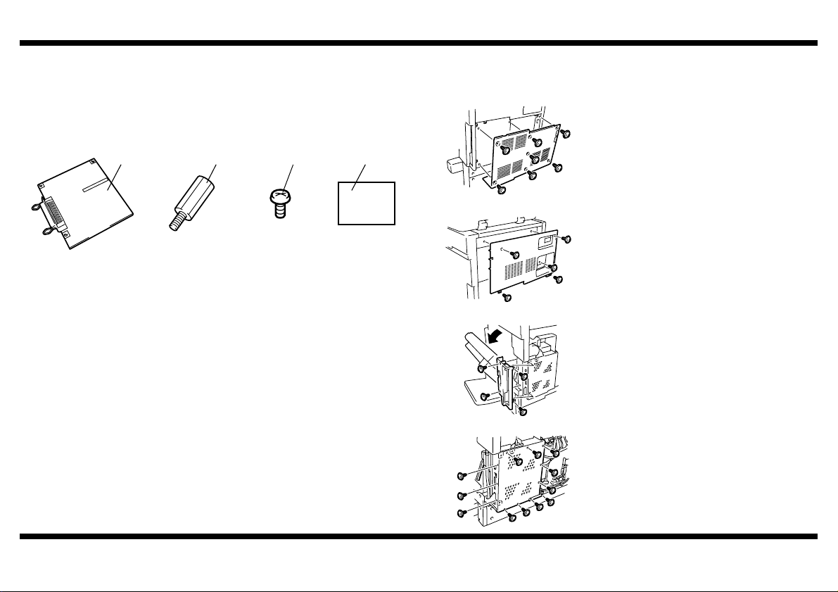
Check that the following accessories are available in the box.
1 Local Interface Board ............................................................................. 1
2 Spacer Screw .........................................................................................3
3 Screw .....................................................................................................2
4 Installation Manual (this manual) ...........................................................1
1 2 3 4
4036U014AA 4036U015AA 9654
■ Installing the Local Interface Kit
1. Turn off the machine and unplug the power
cord from the machine.
2. Remove the lower rear cover (seven
screws).
4348U106AA
3. Remove the upper rear cover (five screws).
4036U001AA
4. Open the right door, and then remove the
right rear cover (four screws).
4036U002AB
5. Remove the shield cover (twelve screws).
– 1 –
4036U003AB
Page 3
EK-501
4036U016AA
4036U017AB
4036U018AA
Ornamental Cover
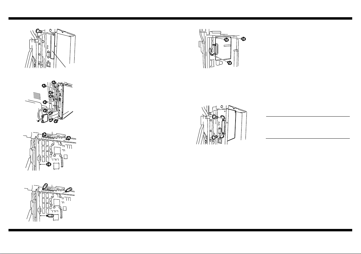
6. Remove the ornamental cover from control
board cover (one screw).
7. Remove screws and disconnect the
connector. Then, remove the control board
cover (nine screws).
8. Remove the three screw fixing the control
board assy.
9. Install three Spacer Screws furnished with
the kit to the control board assy.
10. Connect the local interface board connector
to the PJ10 of the control board assy.
11. Secure the local interface board in position
using three screws which has been removed
in step 8.
4036U020AA
12. Reinstall the control board cover (nine
screws).
13. Secure the connector in position using two
screws furnished with the kit.
NOTE
When tightening the screws, make sure
that the locks of the connector are raised
as shown on the left.
4036U021AA
14. Connect the connector which has been
disconnected in step 7.
15. Reinstall the shield cover (twelve screws).
16. Reinstall the right rear cover (four screws).
17. Reinstall the upper rear cover (five screws).
4036U019AA
18. Reinstall the lower rear cover (seven
screws).
– 2 –
 Loading...