

Konica Minolta DRYPRO793 Installation Manual
LASER IMAGER
DRYPRO MODEL 793
INSTALLATION MANUAL
CODE NO.
0792 (UL), 0791 (CE)
No. 26-2, Nishishinjuku 1-chome, Shinjuku-ku, Tokyo 163-0512, Japan

Table of Contents
Foreword.........................................................................................................1
Ch.1 Pre-installation Information .................................................................9
1.1 Installation Work Flow ......................................................................................10
1.2 External Device Connection Configuration.......................................................11
1.3 Installation Preparations...................................................................................18
1.4 Part Names ......................................................................................................21
1.5 Structure...........................................................................................................27
Ch.2 Unpacking and Installation ................................................................29
2.1 Packing List ......................................................................................................30
2.2 Unpacking ........................................................................................................32
2.3 Checking Accessories ......................................................................................35
2.4 Removing Protection Hardware and Installing Optional Units..........................36
2.4.1 Protection Hardware (Red) List ..........................................................................................36
2.4.2 Removing Protection Hardware Securing Back of Exposure Unit......................................37
2.4.3 Removing Protection Hardware Securing Front of Exposure Unit .....................................38
2.4.4 Removing Protective Film from Exposure Unit Conveyor Rollers ......................................39
2.4.5 Removing Protection Hardware Securing Pickup Unit (X 2 trays) .....................................40
2.4.6 Installing Supply Unit (Option)............................................................................................43
2.4.7 Replacing the Removed Covers (1) ...................................................................................51
2.4.8 Removing Protective Sheet from Heat Processing Unit.....................................................55
2.4.9 Installing Heat Processing Unit ..........................................................................................60
2.4.10 Installing Deodorant Filter and Deodorant Filter Case .......................................................63
2.4.11 Installing Lis-793 (Option) ..................................................................................................65
2.4.12 Installing 1GB Print Memory (Option).................................................................................73
2.4.13 Replacing the Removed Covers (2) ...................................................................................75
2.5 Installing Accessories.......................................................................................76
2.5.1 Installing Exhaust Duct.......................................................................................................76
2.5.2 Installing Film Holder (Cable Protector) (Option) ...............................................................76
2.5.3 Changing Supply Tray Film Size Setting............................................................................77
2.5.4 Installing UPS (Option).......................................................................................................79
2.6 Starting Up .......................................................................................................81
2.6.1 Switching On Power ..................................................................................................................81
Ch.3 Setup ....................................................................................................83
3.1 Outline of DRYPRO 793 Setup ........................................................................83
3.2 Switching to the Service Maintenance Mode ...................................................86
3.3 Switching to the Normal Screen from the Service Maintenance Mode ............87
3.4 Film Setup ........................................................................................................88
3.5 SCP Setup........................................................................................................93
3.6 SCU Setup .......................................................................................................96
3.7 System Setup .................................................................................................102
3.8 User Registration............................................................................................105
3.9 Print Condition Setup .....................................................................................110
3.10 LUT Setup ......................................................................................................118
3.11 Time Set .........................................................................................................124
List of Time Zones .............................................................................................................................127
3.12 Maintenance Schedule ...................................................................................128
3.13 Sorter Setup ...................................................................................................131

Approval Number
11BZ0539
Commercial Name
Laser Imager DRYPRO Vstage MODEL 793
The following Medical Device approval applies:
Ch.4 Checking Image Quality ...................................................................135
4.1 Loading Film...................................................................................................136
4.2 Calibrating Internal Densitometer...................................................................140
4.3 Test Printing ...................................................................................................146
4.3.1 Printing Flat Pattern..........................................................................................................146
4.3.2 Printing SMPTE Pattern ...................................................................................................148
4.3.3 Flat Pattern Justification ...................................................................................................150
4.3.4 SMPTE Pattern Density Justification................................................................................150
4.4 Adjusting Image Data Write Start Position .....................................................154
Ch.5 Printing from and Backup of External Devices..............................159
5.1 Printing from External Devices .......................................................................160
5.2 Backup ...........................................................................................................161
5.2.1 CF Memory Data Backup (CF -> HDD)............................................................................161
5.2.2 Setting Data Backup (DRYPRO 793 -> Maintenance PC) ...............................................162
Ch.6 Web Maintenance Mode ...................................................................165
6.1 Outline of Web Maintenance Mode ................................................................166
6.2 Starting Up and Terminating Web Maintenance Mode ..................................167
6.3 Web Maintenance Mode Menus.....................................................................170
6.3.1 Film Setup
.....................................................................................................................170
6.3.2
SCP Setup
....................................................................................................................172
6.3.3
SCU Setup....................................................................................................................173
6.3.4 Border Custom Set
up ......................................................................................................176
6.3.4
System Setup...............................................................................................................177
6.3.5
User Registration ........................................................................................................179
6.3.6
Print Condition Setup.................................................................................................181
6.3.7
LUT Setup
.....................................................................................................................186
6.3.8
Setting Current Time and Date...............................................................................188
6.3.9
Maintenance Schedule Setup .................................................................................190
6.3.10
Sorter Setup .................................................................................................................191
Specifications.............................................................................................193


< 1 >
DRYPRO Vstage MODEL 793 Installation Manual Ver.1.00 2004.11
Foreword
This section sets out information with which the
service engineers must familiarize themselves before
proceeding with installation.

Foreword
< 2 >
DRYPRO Vstage MODEL 793 Installation Manual Ver.1.00 2004.11
1. To ensure safety, only qualified service engineers are permitted to open external covers or touch internal
components.
2. The device incorporates a laser unit (Class IIIb). Exposure of the eyes to the laser may result in serious injury.
Protective goggles must be worn at all while carrying out adjustments or repairs.
3. Under no circumstances should procedures or adjustments not detailed in this manual be attempted. Doing so
may result in harmful electromagnetic wave emissions.
4. Cautions indicated on warning levels must be observed at all times to ensure safety.
5. The device incorporates high-voltage components. Touching such components may result in electric shock:
care must be exercised.
6. Caution must be exercised to ensure that body parts or clothing do not become trapped in moving parts in the
device such as fans.
7. The weight of the device is approximately 255kg (285kg with sorter). Sufficient space to ensure safety must be
allowed during unpacking and installation.
8. Electrical circuitry in the device may be damaged by generation of static electricity. Care must be taken when
effecting repairs in handling both the main body and removed components.
9. Always ensure that the device power supply is switched off before disconnecting or connecting cables or
connectors. Under absolutely no circumstances should such procedures be attempted with the power supply on:
doing so may result in serious accidents.
10. Anti-static wrist bands must be worn at all times when handling circuit boards.
11. The device incorporates a lithium battery. Failure to follow correct procedure when replacing the battery may
result in damage: replacement should be carried out by a qualified service engineer.
12. DRYPRO 793 is a Class I laser device and is equipped with an interlock. The procedures detailed in this manual
must be followed when disengaging the interlock.
13. Disposal of the DRYPRO 793 main body (lithium battery (including hexavalent chromium, cadmium, mercury,
PBB, PBDE), fluorescent tube (in liquid crystal module), accessories, options, consumables, packing materials
and film must be carried out in accordance with relevant local ordinances and regulations.
Cautions Regarding Installation
The following cautions must be read before proceeding with installation and strictly observed.
Foreword
< 3 >
DRYPRO Vstage MODEL 793 Installation Manual Ver.1.00 2004.11
Warning Text (Signal Word)
Signal words indicate the degree of potential hazards in the product.
There are 3 degrees of caution levels, and each is used depending on the level of risk and damage caused by
incorrect use and mishandling.
DANGER
: Failure to observe the caution will produce high risk of serious or fatal injury.
WARNING
: Failure to observe the caution will produce moderate risk of serious or fatal injury.
CAUTION
: Failure to observe the caution will produce risk of moderate or light injury.
or damage to property.
Risk of the damage
Bodily injury
(and damage to property)
Damage to property only
Loss of life or serious injury
(Damage is serious)
High Low
DANGER WARNING
WARNING or CAUTION CAUTION
CAUTION
Moderate damage or light injury
(Damage is light)
Foreword
< 4 >
DRYPRO Vstage MODEL 793 Installation Manual Ver.1.00 2004.11
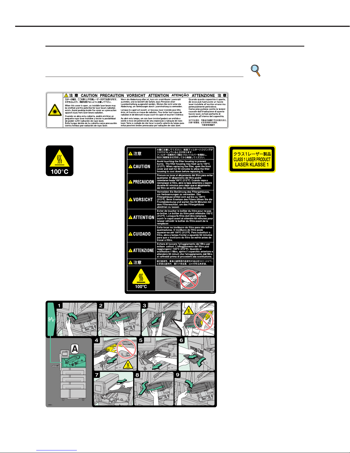
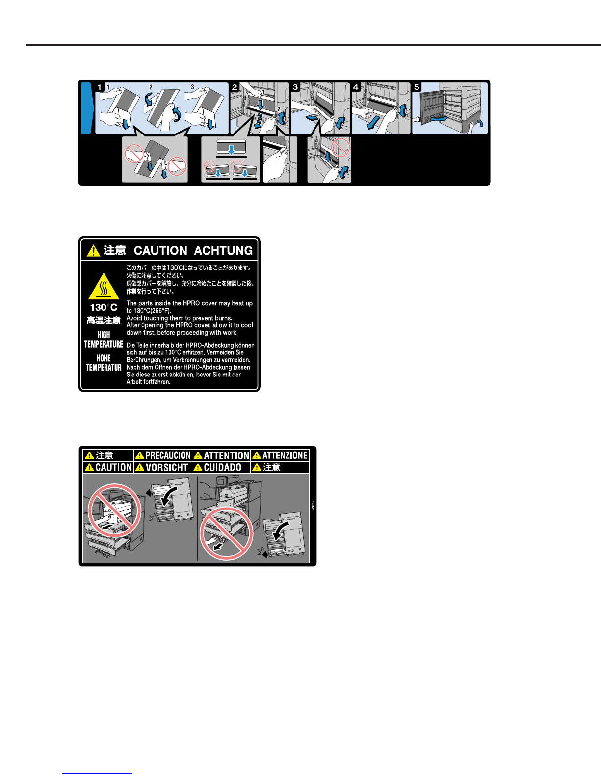
Warning Labels
Warning labels on the DRYPRO 793 are affixed at the locations shown below, and indicate possible danger
to the user.
Description of Warning Labels
p.7 Locations of
Warning
Labels
(1) Laser Caution Label
(2) High Temp. 100
: Label-1
(4) Class1 Laser Product Label
(5) Jam Release Label-A
(3) High Temp. 100: Label-2
Foreword
< 5 >
DRYPRO Vstage MODEL 793 Installation Manual Ver.1.00 2004.11
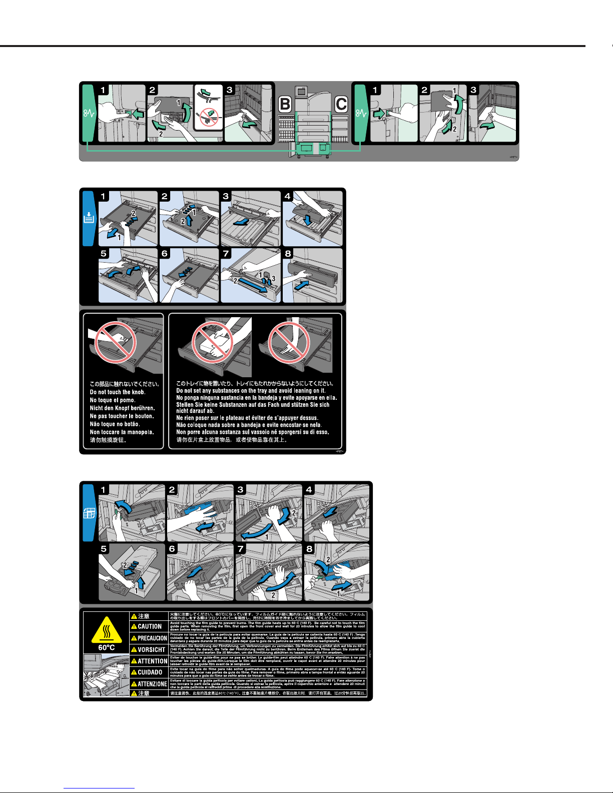
(7) Film Loading Label
(8) Deodorant Filter Change Label
(6) Jam Release Label-B•C
Foreword
< 6 >
DRYPRO Vstage MODEL 793 Installation Manual Ver.1.00 2004.11
(10) High Temp. 130: Label
(11) Label Indicating Danger of Toppling
(9) Cleaning Roller Cleaning Label
Foreword
< 7 >
DRYPRO Vstage MODEL 793 Installation Manual Ver.1.00 2004.11
To avoid the risk of
burns or electrocution,
ensure that labels do
not become grimy.
Labels that have
become illegible or have
peeled off should be
replaced.
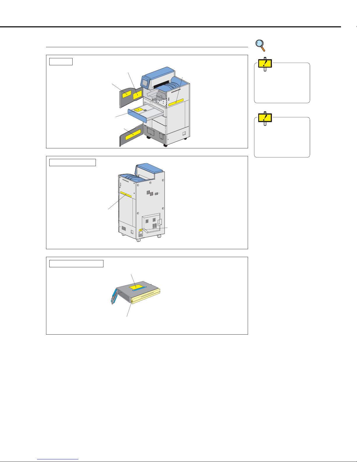
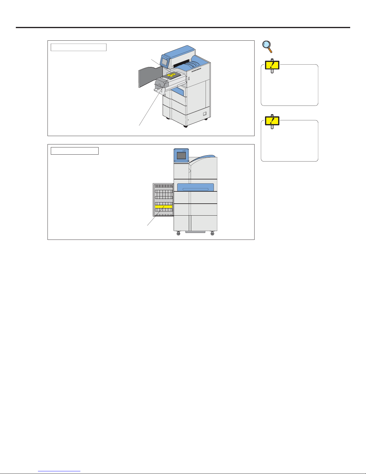
Locations of Warning Labels
p.4 Description
of Warning
Labels
(6) Jam Release Label B-C
(5) Jam Release Label A
(8) Deodorant Filter Change Label
(1) Laser caution Label
(7) Film Loading Label
(1) Laser Caution Label
(4) Class 1 Laser Product Label
Internal
Rear and Left Side
(3) Deodorant Filter Housing High Temp. 100; Label
(2) High Temp. 100; Label
Deodorant Filter Case
Foreword
< 8 >
DRYPRO Vstage MODEL 793 Installation Manual Ver.1.00 2004.11
(11) Label Indicating Danger of Toppling
(10) High Temp. 130; Label
HPRO Unit Cover
To avoid the risk of
burns or electrocution,
ensure that labels do
not become grimy.
Labels that have
become illegible or have
peeled off should be
replaced.
p.4 Description
of Warning
Labels
(9) Cleaning Roller Cleaning Label
Cleaning Rollers

DRYPRO Vstage MODEL 793 Installation Manual Ver.1.00 2004.11
< 9 >
Pre-installation
Information
This chapter presents information to be read and
assimilated before proceeding with installation.
1
Chap.
Ch.1 Pre-installation Information
< 10 >
DRYPRO Vstage MODEL 793 Installation Manual Ver.1.00 2004.11
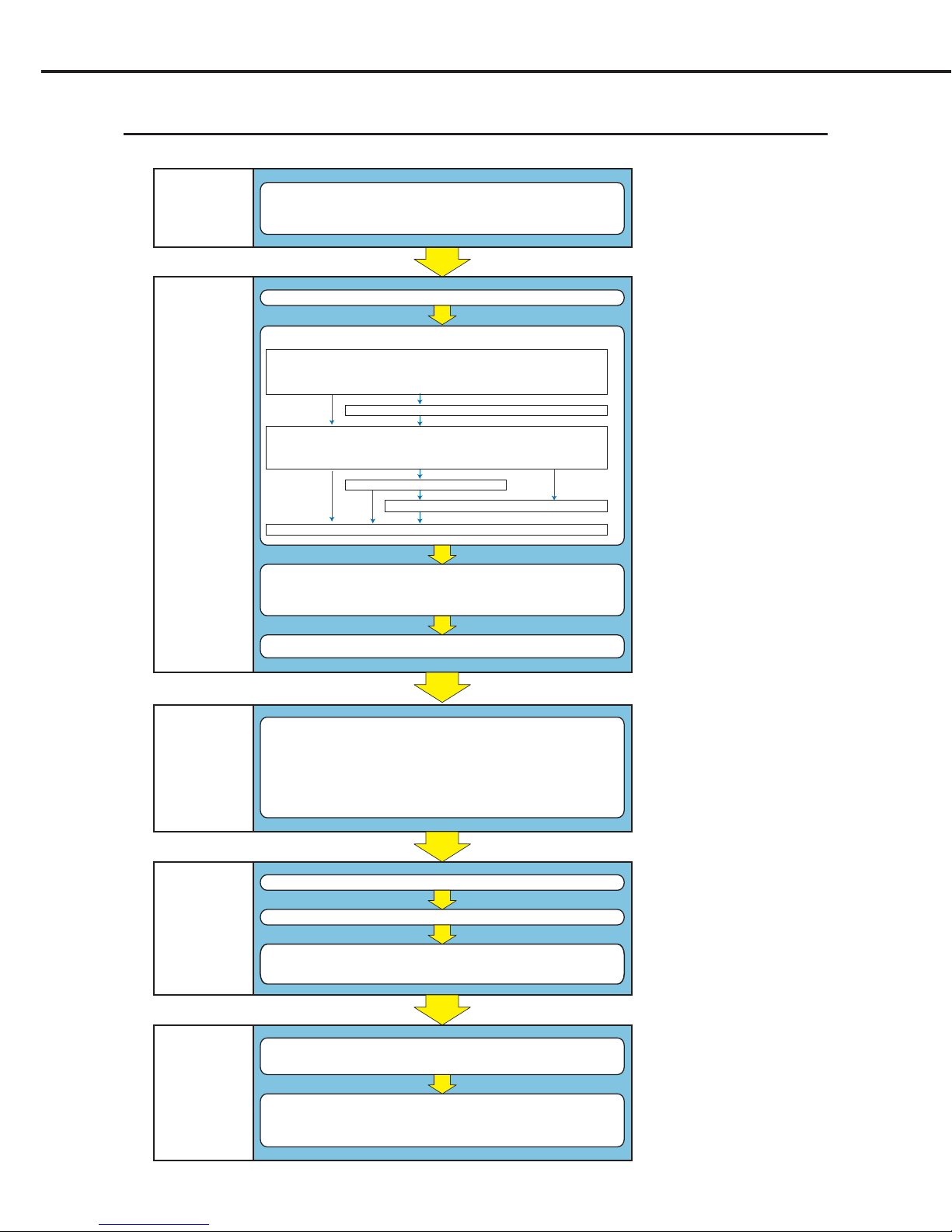
1.1 Installation Work Flow
For maximum efficiency, the installation procedure should be carried out in the sequence detailed below.
Checking Image
Quality
(Ch.4)
Removing Potective Hardwares and installing options
2.4.2 Removing Potective Hardware Securing Back of Exposure Unit (p.00)
2.4.3 Removing Potective Hardware Securing Front of Exposure Unit (p.00)
2.4.4 Removing Protective Sheet from Exposure Unit Conveyor Rollers (p.00)
2.4.5 Removing Potective Hardware Securing Pickup Unit (X 2 trays) (p.00)
2.4.7 Installing Cover (1) (p.00)
2.4.8 Removing Protective Sheet from Heat Processing Unit (p.00)
2.4.9 Installing Heat Processing Unit (p.00)
2.4.10 Installing Deodorant Filter and Deodorant Filter Case (p.00)
2.4.13 Installing Cover (2) (p.00)
Preparations
- Checking installation conditions (p.00)
- Checking the network (p.00)
- Preparation of tools (p.00)
Service Maintenance Mode Settings
(Operation Panel or WEB maintenance PC)
3.4 Film Settings (p.00)
3.5 SCP Settings (p.00)
3.6 SCU Settings (p.00)
3.7 System Settings (p.00)
3.8 User Registration (p.00)
3.9 Print Condition Settings (p.00)
3.10 LUT Settings (p.00)
3.11 Setting Current Time and Date (p.00)
3.12 Regular Inspection Settings (p.00)
3.13 Sor ter Settings (p.00)
Test Printing
Start Up
Installing Accessories
- Exhaust Duct (p.00)
- Film Holder (p.00)
- UPS (Option)
Unpacking (p.00)
Installation
(Ch.2)
Preparations
(Ch.1)
Settings
(Ch.3)
- Flat Pattern Printing (p.00) - SMPTE Pattern Printing (p.00)
Calibration of Internal Densitometer (p.00)
Loading film (p.00)
Printing
from and Backup
of External
Devices
(Ch.5)
Checking printing from external devices
(Network cable connections, clamp installation)
(p.00)
Backup
- CF Memory Data Backup (CF -> HDD) (p.00)
- Setting Data Backup (DRYPRO 793 -> Maintenance PC) (p.00)
2.4.6 Installing Supply Unit (Option) (p.00)
2.4.11 Installing Lis-793 (p.00)
2.4.12 Installing 1GB Print Memory (p.00)
Ch.1 Pre-installation Information
< 11 >
DRYPRO Vstage MODEL 793 Installation Manual Ver.1.00 2004.11
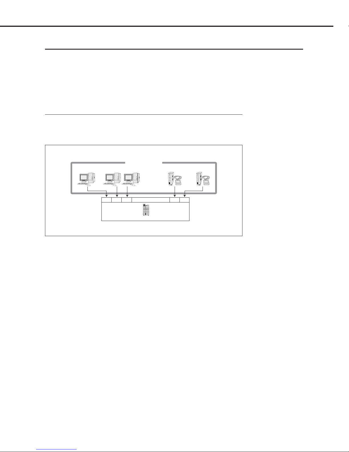
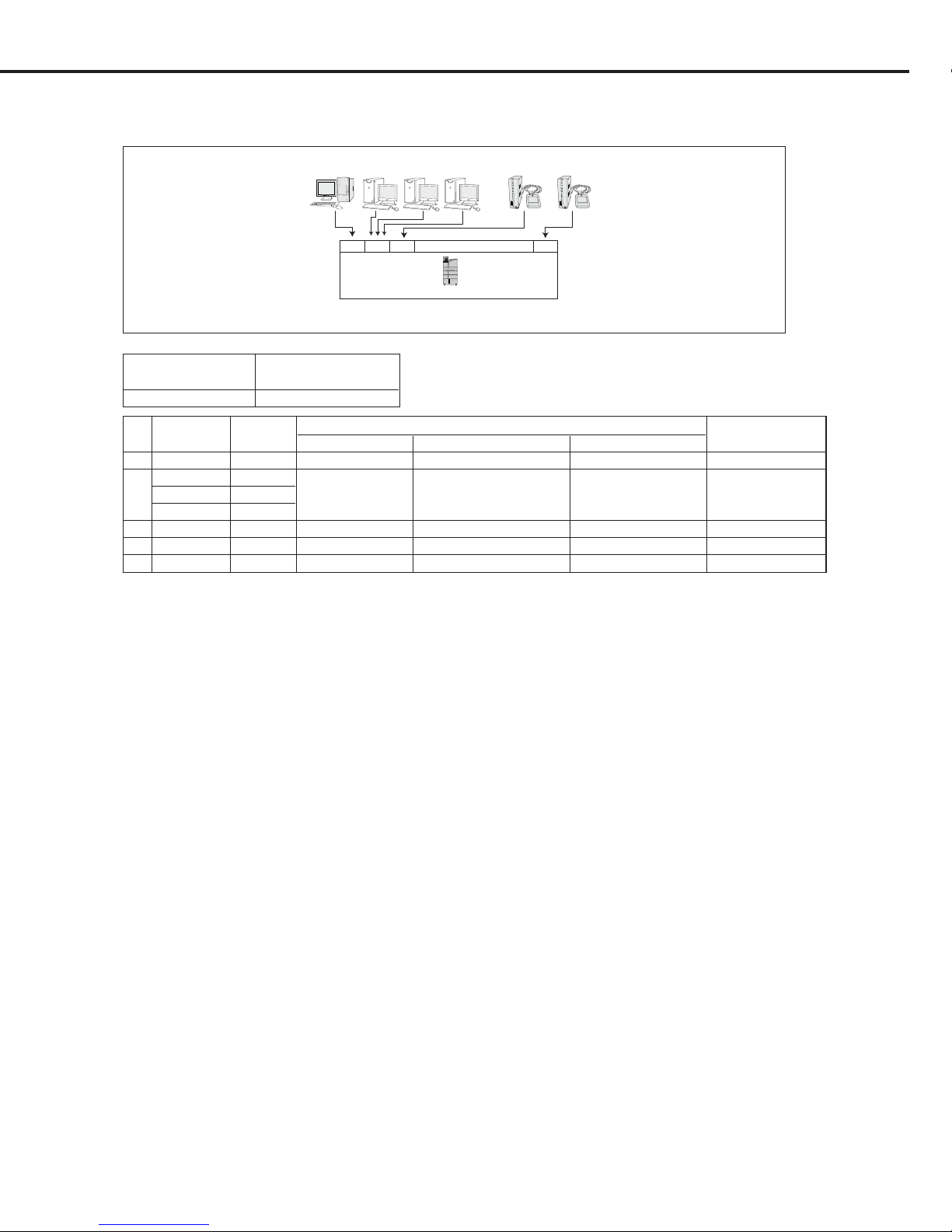
1.2 External Device Connection Configuration
This section details the configuration of external device connection to DRYPRO 793.
Normally, DRYPRO 793 has a maximum external device connection capacity of 16CH. (Basic specification)
In cases where capacity in excess of 16CH is required, or where multiple devices are to be connected under
the same settings, connection of up to 20CH is possible under certain conditions. (Expanded port
specification)
The connection configurations are shown below.
1.2.1 Basic Specification
In the basic specification, DRYPRO 793 has a maximum external device connection capacity of
16CH.
In cases where devices of other manufacturers are to be connected for direct DICOM input, a
DRYPRO multi-client license is required for the 2ch or more.
Total : 16 devices
CH1 CH2 CH3
. . . . . . . . . . . .
. . . . . . . . . . . . . .
CH15 CH16
Printlink3 Printlink3CS-1 CS-1 CS-1
DRYPRO 793
Example of 16ch in the Basic Specification

Ch.1 Pre-installation Information
< 12 >
DRYPRO Vstage MODEL 793 Installation Manual Ver.1.00 2004.11
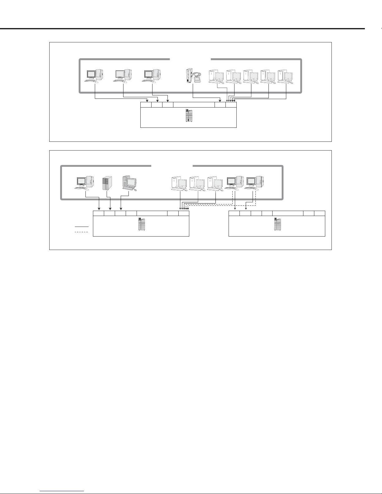
1.2.2 Expanded Port Specification
Conditions
The expanded port specification includes 5ch in addition to 15ch of the basic specification,
producing a total of 20ch.
The expanded channel configuration enables connection of a maximum of five additional
external devices to 1ch of the basic specification. The following conditions apply to the
external devices connected to the expanded port.
1. No. of Expanded ch : 5ch
2. Devices that may be connected : KDIS devices (RS Series, IS Series, Liteview)
REGIUS Series (backup settings only)
3. No. of sheets to be processed : Devices with maximum daily print count of 20
sheets.
4. Setting Restrictions : Unlike the basic specification, channel-specific LUT
settings or print condition settings cannot be made
for external devices connected to the expanded
5ch.
The LUT setting is fixed at linear and the print
condition settings are common to the expanded
5ch.
5. Preparations : Before making expanded port settings, the Konica
Minolta sales department should be contacted for
details of system drawings.
Settings
In normal SCU settings, the "expanded port no." + "AE Title" setting is essential: with
DRYPRO 793, however, additional channels may be allocated to a 1ch expanded port without
AE title. (The port to which the additional channels are to be allocated is determined under
[SERVICE 1] - [SCP SETUP].
Use of the expanded port enables connection of a maximum of 20ch.
The expanded port and AE title of the external devices connected are set in the blank column.
Ch.1 Pre-installation Information
< 13 >
DRYPRO Vstage MODEL 793 Installation Manual Ver.1.00 2004.11
Total: 20 Devices
LiteViewPrintlink3CS-1 CS-1 CS-1 Liteview Liteview Liteview Liteview
CH1 CH2 CH3
. . . . . . . . . . .
. . . . . . . . . .
CH15 CH16
DRYPRO 793
Total: 20 Devices
. . . . . . . . . . . .
LiteViewREGIUS IMPrintlink2CS-1/CS-2 CS-1/CS-2 CS-1/CS-2Liteview Liteview
Backup
Standard
CH1 CH2 CH3 CH4
. . . . . . . . . . .
CH15 CH16
DRYPRO 793
CH1 CH2 CH3 CH4
. . . . . . . . . .
CH15 CH16
DRYPRO 793
Example of 15ch Basic Specification + 5ch Expanded Port Specification
Example of 15ch Basic Specification + 5ch Expanded Port Specification (2ch set as backup)
Ch.1 Pre-installation Information
< 14 >
DRYPRO Vstage MODEL 793 Installation Manual Ver.1.00 2004.11
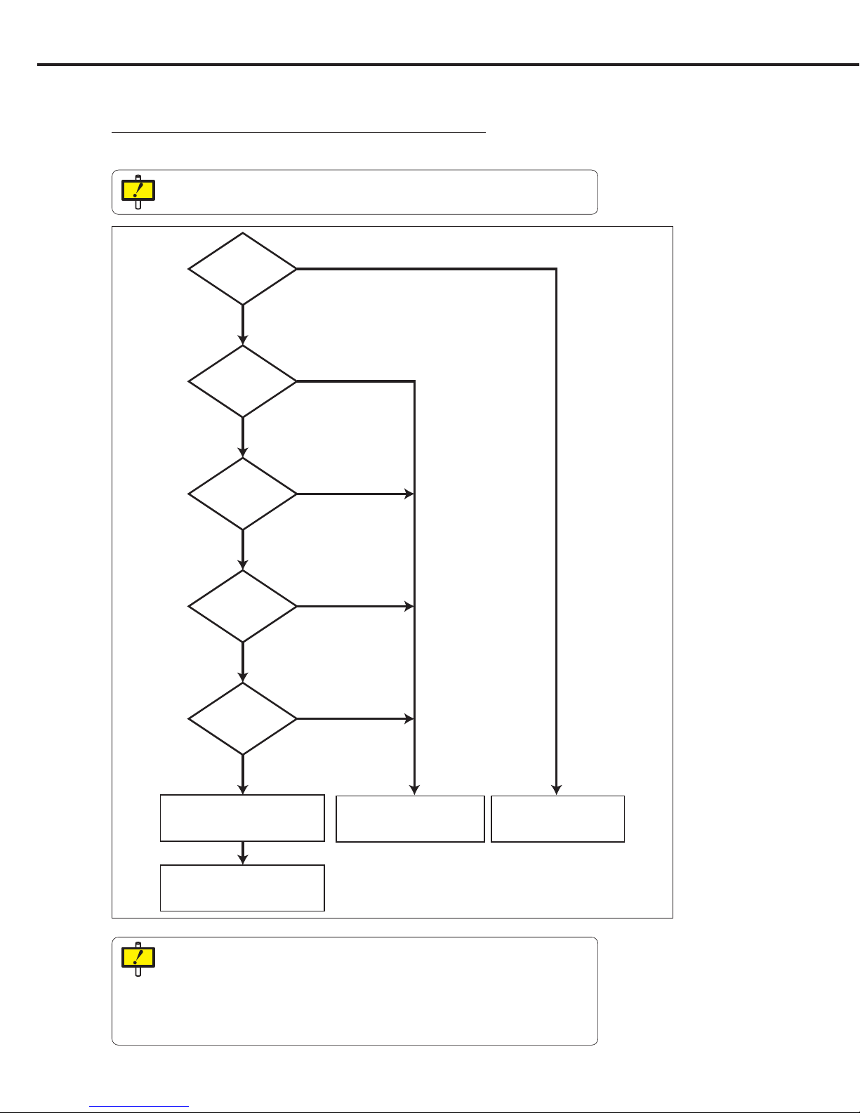
Connection to
17 or more external
devices?
Connection to
20 or fewer external
devices?
2 or more
devices connected to
the expanded
port?
5 or fewer
devices connected to
the expanded
port?
3 or fewer
devices connected to
the expanded
port?
Connection in the
expanded port specification
should be made to 1 DRYPRO 793.
External devices should be
connected to 2 or more
DRYPRO 793 units.
Connections should be made
to 1 DRYPRO 793 unit is
the basic specification.
YES
NO
NO
NO
NO
NO
YES
YES
YES
YES
Adjustments should be made so
that three of the external devices are
not allocated to the expanded port.
Flow Chart Showing Determination of Basic
Specification/Expanded Port Specification
A flow chart showing how to determine whether the connections should be made in the basic or
expanded port specification is set out below.
In cases where there is sufficient space and more than one DRYPRO 793 installed,
the basic specification should be selected.
Conditions for devices allocated to the expanded port.
- KDIS devices (RS Series, IS Series, Liteview) or REGIUS Series (backup settings
only)
- Maximum daily print count of 20 sheets per device.
- LUT setting fixed to "linear".
- Print conditions common to the additional 5ch.

Ch.1 Pre-installation Information
< 15 >
DRYPRO Vstage MODEL 793 Installation Manual Ver.1.00 2004.11
Illustrations of Examples of Basic/Expanded Port
Specification Settings
Differences in settings between the connections in basic and expanded are detailed below.
CH
Connected Connection SCU Setting
Print Condition SETUP,
Device Spec. Use of Input Device Input Device IP Address Input Device AE Title
LUT SETUP
1 CS-1 Basic ON 192.168.20.90 KC_CS1L_U001
Individual Settings Possible
2 CS-1 Basic ON 192.168.20.91 KC_CS1L_U001
Individual Settings Possible
3 CS-1 Basic ON 192.168.20.92 KC_CS1L_U001
Individual Settings Possible
... ... ... ... ... ... ...
15 PrintLink3 Basic ON 192.168.20.104 KC_PRINK3_U001
Individual Settings Possible
16 PrintLink3 Basic ON 192.168.20.105 KC_PRINK3_U002
Individual Settings Possible
SCP SETUP
Expanded Port Channel Function
DRYPRO 793 NO SELECT
Illustration of Example or Basic Configuration Settings
(Connection to 16 external devices in basic configuration.)
Total : 16 devices
CH1 CH2 CH3
. . . . . . . . . . . .
. . . . . . . . . . . . . .
CH15 CH16
Printlink3 Printlink3CS-1 CS-1 CS-1
DRYPRO 793
p.93 SCP SETUP
p96 SCU SETUP
Ch.1 Pre-installation Information
< 16 >
DRYPRO Vstage MODEL 793 Installation Manual Ver.1.00 2004.11
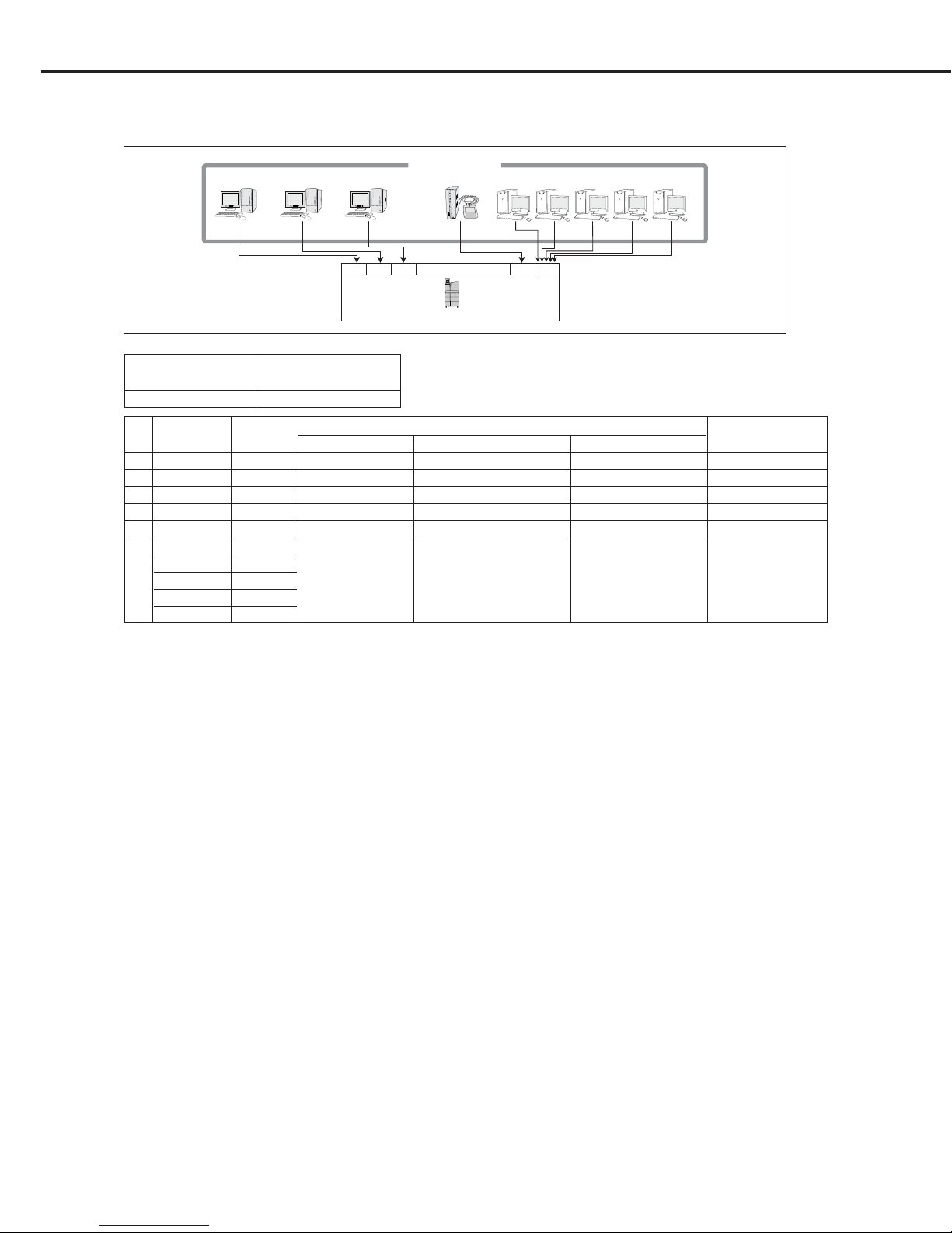
Illustration of Example for Expanded Port Configuration Settings 1
(Connection to 20 external devices with CH4 set as the expanded port)
Total: 20 Devices
LiteViewPrintlink3CS-1 CS-1 CS-1 Liteview Liteview Liteview Liteview
CH1 CH2 CH3
. . . . . . . . . . .
. . . . . . . . . .
CH15 CH16
DRYPRO 793
CH
Connected Connection SCU Setting
Print Condition SETUP,
Device Spec. Use of Input Device Input Device IP Address Input Device AE Title
LUT SETUP
1 CS-1 Basic ON 192.168.20.90 KC_CS1L_U001
Individual Settings Possible
2 CS-1 Basic ON 192.168.20.91 KC_CS1L_U001
Individual Settings Possible
3 CS-1 Basic ON 192.168.20.92 KC_CS1L_U001
Individual Settings Possible
... ... ... ... ... ... ...
15 PrintLink3 Basic ON 192.168.20.104 KC_PRINK3_U001
Individual Settings Possible
LiteView Expanded
LiteView Expanded
16 LiteView Expanded ON (Blank) (Blank)
Common Settings
LiteView Expanded
LiteView Expanded
SCP SETUP
Expanded Port Channel Function
DRYPRO 793 CH 16
Ch.1 Pre-installation Information
< 17 >
DRYPRO Vstage MODEL 793 Installation Manual Ver.1.00 2004.11
Illustration of Example for Expanded Port Configuration Settings 2
(Connection to 20 external devices with CH2 set as the expanded port)
Liteview Printlink3 Printlink3CS-1 Liteview Liteview
CH1 CH2 CH3
. . . . . . . . . . . . . .
CH16
DRYPRO 793
CH
Connected Connection SCU Setting
Print Condition SETUP,
Device Spec. Use of Input Device Input Device IP Address Input Device AE Title
LUT SETUP
1 CS-1 Basic ON 192.168.20.90 KC_CS1L_U001
Individual Settings Possible
LiteView Expanded
2 LiteView Expanded ON (Blank) (Blank)
Common Settings
LiteView Expanded
3 PrintLink3 Basic ON 192.168.20.92 KC_PRINK3_U001
Individual Settings Possible
... ... ... ... ... ... ...
16 PrintLink3 Basic ON 192.168.20.104 KC_PRINK3_U001
Individual Settings Possible
SCP SETUP
Expanded Port Channel Function
DRYPRO 793 CH 2
Ch.1 Pre-installation Information
< 18 >
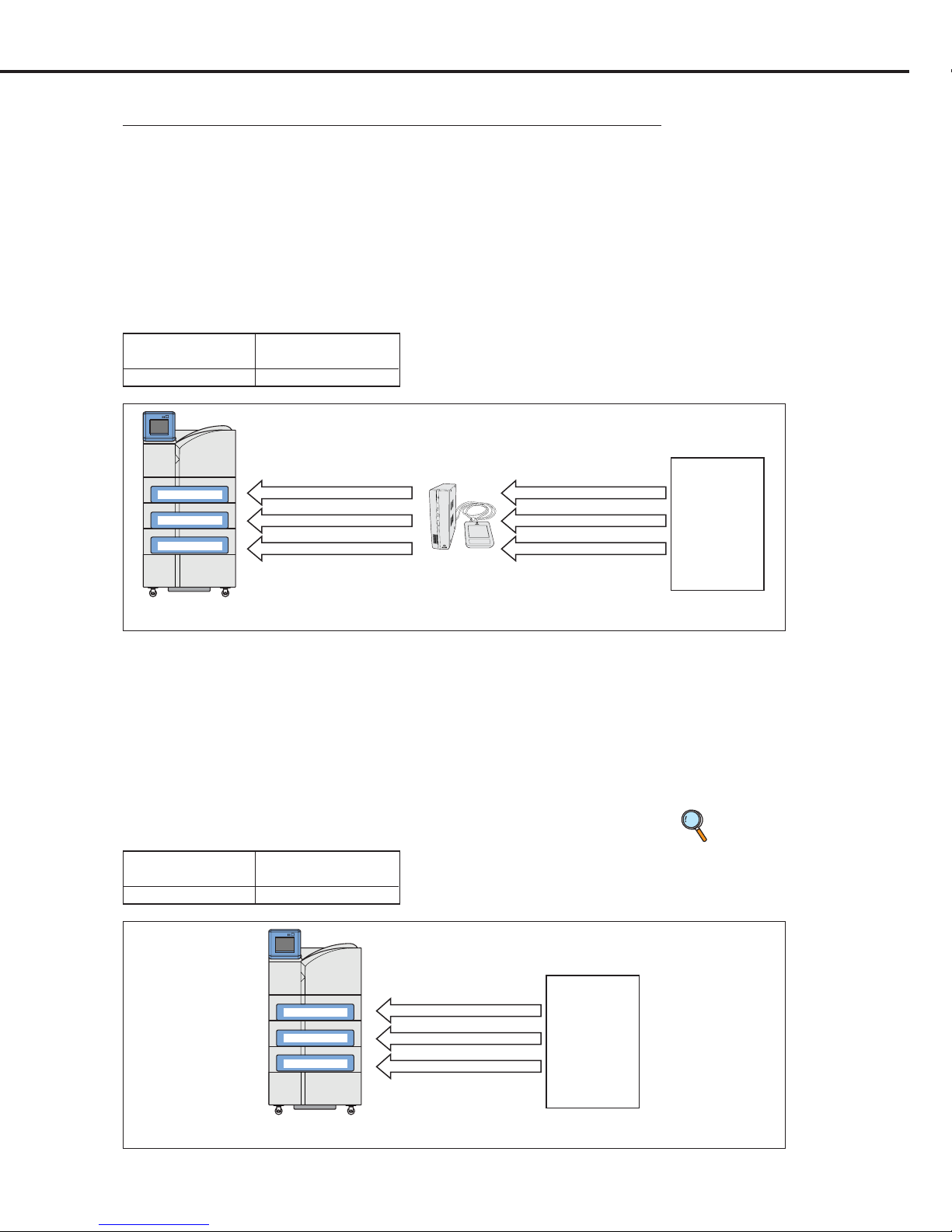
DRYPRO Vstage MODEL 793 Installation Manual Ver.1.00 2004.11
Connected to CS3 (Venus PCM Mode)
CS-3DRYPRO 793
14x17 BLUE Dmax3.0
11x14 DR BLUE Dmax4.0
8x10 DR BLUE Dmax4.0
Tray-1 : 14x17 B
Tray-2 : 11x14 M
Tray-3 : 8x10 M
SCU Setting
Size Type Check
DRYPRO 793 ON
1.2.3 25µ Output
For a Regius-PCM system, the DRYPRO 793 super-fine mode (25µm) is required.
For connections to Regius contact mammography/normal photography and other modalities, the
normal mode (43.7µm) is used.
DRYPRO 793 requires the conditions shown below for 25µm output.
- 1GB expanded print memory.
- Loaded with mammography-dedicated film (film type <M>).
An example of output in the 25µm mode is shown below.
For 25um output, a command for output on the "DR BLUE FILM" film type must be
sent from CS-3.
For 25um output, giga-bit Ethernet is recommended to ensure a large image size.
Ch.1 Pre-installation Information
< 19 >
DRYPRO Vstage MODEL 793 Installation Manual Ver.1.00 2004.11
Connection to Devices of other Manufacturers Using Printlink
The "BLUE FILM" output command from devices of other manufacturers must be converted to
"DR BLUE FILM" (Konica Minolta's unique standard) and sent to DRYPRO 793. For details of he
method of conversion and other relevant information, refer to the Printlink Manual.
Printlink
DRYPRO 793
14x17 BLUE Dmax3.0
11x14 DR BLUE Dmax4.0
8x10 DR BLUE Dmax4.0
14x17 BLUE Dmax3.0
11x14 BLUE Dmax4.0
8x10 BLUE Dmax4.0
Device of Other
Manufacturer
Tray-1 : 14x17 B
Tray-2 : 11x14 M
Tray-3 : 8x10 M
SCU Setting
Size Type Check
DRYPRO 793 ON
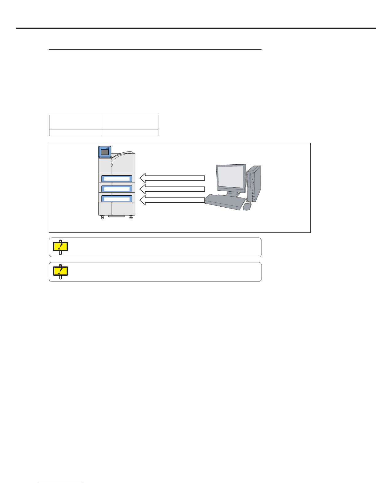
1.2.4 Mammo-film Output
In mammo-mode of other manufacturers, DRYPRO 793 high-density output (Dmax 4.0) is
required. For Regius normal photography and other modalities, Dmax 3.0 is used.
DRYPRO 793 requires the conditions shown below for Dmax 4.0 output.
- Loaded with mammography-dedicated film (film type <M>).
An example of mammo-film output is shown below.
Connection with Devices of other Manufacturers without Printlink
To send a direct output command from the device that cannot change the Dmax, the following
settings must be made in DRYPRO 793.
[PRINT SETUP]
[PRINT CONDITION]
[Maximum density] : "400"
[Maximum/minimum density value used] : "DICOM"
[Parameter priority setting] : DENSITY MAX set to ON.
DRYPRO 793
14x17 BLUE Dmax3.0
11x14 BLUE Dmax4.0
8x10 BLUE Dmax4.0
Device of Other
Manufacturer
Tray-1 : 14x17 B
Tray-2 : 11x14 M
Tray-3 : 8x10 M
SCU Setting
Size Type Check
DRYPRO 793 OFF
p.110 PRINT
CONDITION
SETUP
Ch.1 Pre-installation Information
< 20 >
DRYPRO Vstage MODEL 793 Installation Manual Ver.1.00 2004.11
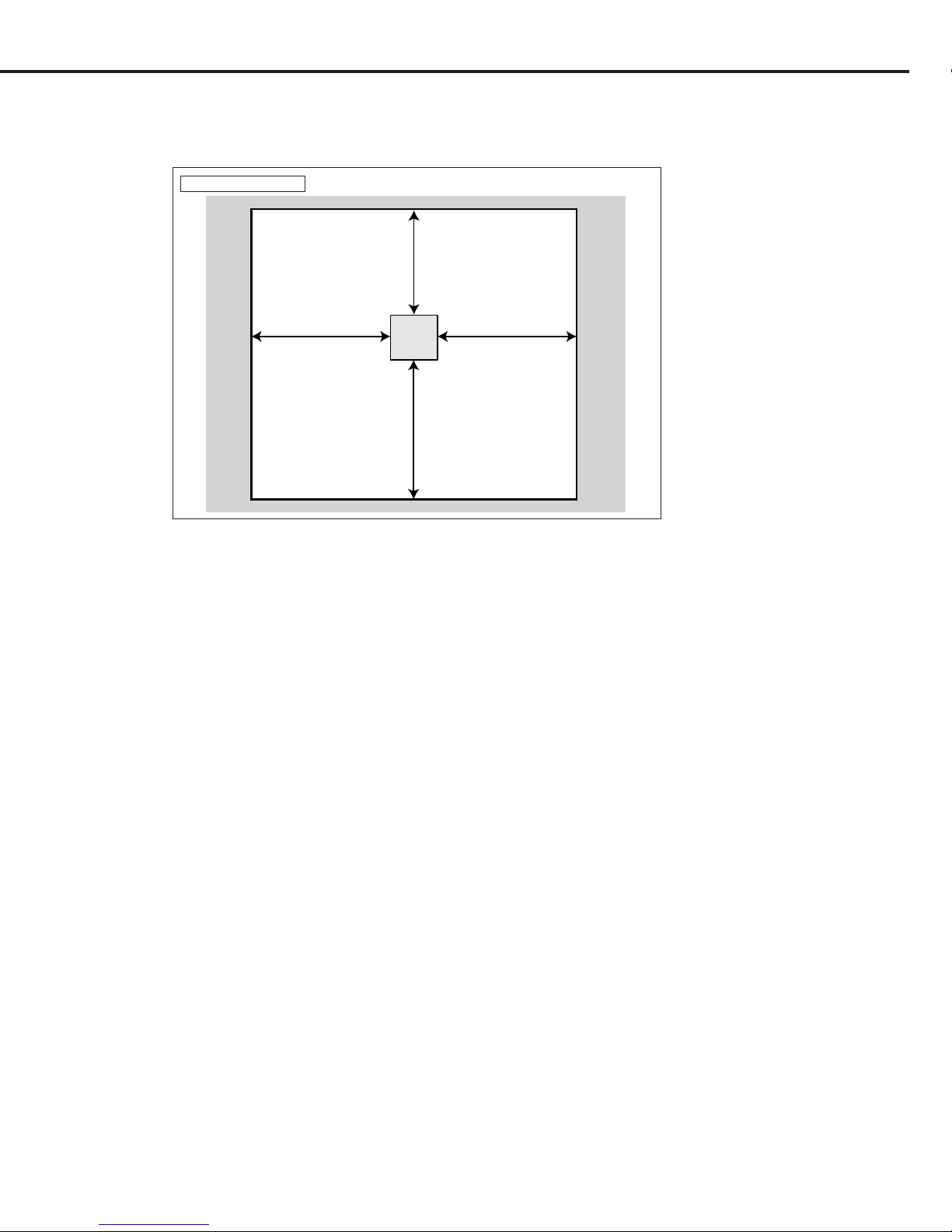
1.3 Installation Preparations
The following items should be checked before proceeding with installation.
1.3.1 1Checking Installation Conditions
Check to ensure that the place of installation meets the following requirements.
Checking the Place of Installation
- There must be no risk of exposure to water.
- There must no risk of exposure to the harmful effects of high pressure, extreme
temperatures, humidity, poor ventilation, direct sunlight, dust, salt, combustible
gases or sulphur.
- There must be no risk of tilting, exposure to vibration or shock (including transport).
- There must be no chemicals must be stored at the place of installation.
- There must be no risk of gaseous emissions.
- Ventilation must be sufficient to disperse any odours produces by DRYPRO 793.
- There must be sources of noise in the vicinity.
- There must be sufficient space to ensure that there will be no risk of tripping over or
pulling on power or ethernet cables.
- There must be sufficient space to ensure that air inlets and outlets at the side and
rear of the unit are not obstructed.
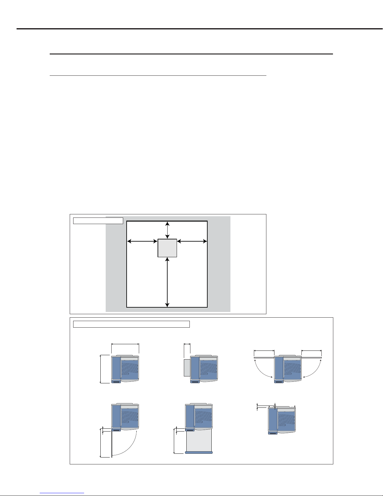
- The installation space must meet the dimensional requirements shown below.
1000mm minimum
100mm minimum
500mm minimum
DRYPRO
793
Front of
Main Body
500mm minimum
Installation Space
630mm
740mm
195mm
460mm
With upper and lower front covers open
(to replace deodorant filter or resolve jams)
With supply tray open (to load films)
With ejection panel open (to resolve jams)Normal
When installing exhaust duct and clamp
675mm
54mm
26mm
With left/right panels open (to resolve jams)
62mm
580mm
62mm
460mm
Maximum Space Requirements for DRYPRO 793
Ch.1 Pre-installation Information
< 21 >
DRYPRO Vstage MODEL 793 Installation Manual Ver.1.00 2004.11
Checking Power Supply Conditions
Check to ensure that a power outlet meeting the requirements below is available at
the place of installation.
- Voltage : AC120V (UL), AC220V-240V (CE)
- Frequency : 60Hz (UL), 50/60Hz (CE)
- Maximum current consumption: 9A(UL), 4.5A(CE)
- Ground : Type D
Checking the Place of Unpacking
Check to ensure that a space of 2.5m or more is allowed at the front (the side where
the locking screws are located) of the palette.
When unpacking DRYPRO 793, be sure to unload the unit from the front of the
palette.
Checking the Route of Transportation
Check to ensure that the route from the place of unpacking and the place of
installation meets the following requirements.
- Ensure that there are no steep gradients or steps that are likely to expose
DRYPRO 793 to shocks during transport.
- Ensure that entrances into and exits from any rooms through which DRYPRO 793
will be transported are of adequate dimensions to allow safe passage.
- Ensure that the floors on the rout of transportation are capable of supporting the
weight of DRYPRO 793 (approximate weight: 255kg (without sorter), 285kg (with
sorter) without warping or buckling.
Checking the Area where Power and Ethernet Cables will be Laid
The person responsible for laying cables must check the following items.
- The location of the hub to which DRYPRO 793 will be connected, the route along
which the Ethernet cable will be laid and the required cable length.
- The location of the power outlet (3P) to which DRYPRO 793 will be connected, the
route along which the power cable will be laid and the required cable length.
Check also to ensure that cables will be laid along a safe route, not, for example,
crossing corridors.
Checking Maintenance Space
Check to ensure that the place of installation allows for the maintenance space
dimensions shown below.
1000mm minimum
1000mm minimum 1000mm minimum
800mm minimum
DRYPRO
793
Front of
Main Body
Maintenance Space

Ch.1 Pre-installation Information
< 22 >
DRYPRO Vstage MODEL 793 Installation Manual Ver.1.00 2004.11
1.3.2 Checking the Network
The following points should be checked with the facility network administrator in advance of
installation.
DRYPRO 793 (SCP) Related Settings
- IP addresses and sub-net masks (when DHCP server is not used) of DRYPRO
793, maintenance PC and gateways.
- DRYPRO 793 host name.
- DRYPRO 793 AE title and port number (print service).
Diagnostic Device Related Settings
- Number of diagnostic devices connected to DRYPRO 793.
- IP address of each diagnostic device.
- AE title of each diagnostic device.
- Port number of each diagnostic device (N-EVENT REPORT service).
- Print conditions used by each diagnostic device (format, film size).
Maintenance PC
- Model with 10BaseT/100BaseTX/1000BaseT network ports.
- PC with TCP/IP protocol installed.
- PC with Windows2000/XP OS.
- PC with Internet Explorer (version 5.5 or higher).
- PC with environment capable of executing Java script with the Web browser.
Equipment for Network Connection
- Hub (Used for direct connection to DRYPRO 793 and maintenance PC).
Hub with auto-negotiation capabilities as 100Base-TX hub recommended.
- Ethernet Cables
(For DRYPRO 793 -> Hub connection and maintenance PC -> Hub connection)
CAT5E or CAT6 should be used for 1000Base-T.
Tools
- Box Cutter
- Phillips screw driver
- Long phillips screw driver (90mm or longer) for disengaging the front cover lock.
- Flat head screw driver
- Radio pliers
- 13mm box wrench (with a long section below the neck). Alternatively, socket
wrench (with extension cover)
- Portable densitometer: X-Rite 331 (used to check image)
- Magnifying glass (used to check image)
1.3.3 Equipment and Tools Required for Installation
Before proceeding with installation, check to ensure that the following equipment and tools are
available.
p.93 SCP SETUP
p.96 SCU SETUP
Ch.1 Pre-installation Information
< 23 >
DRYPRO Vstage MODEL 793 Installation Manual Ver.1.00 2004.11
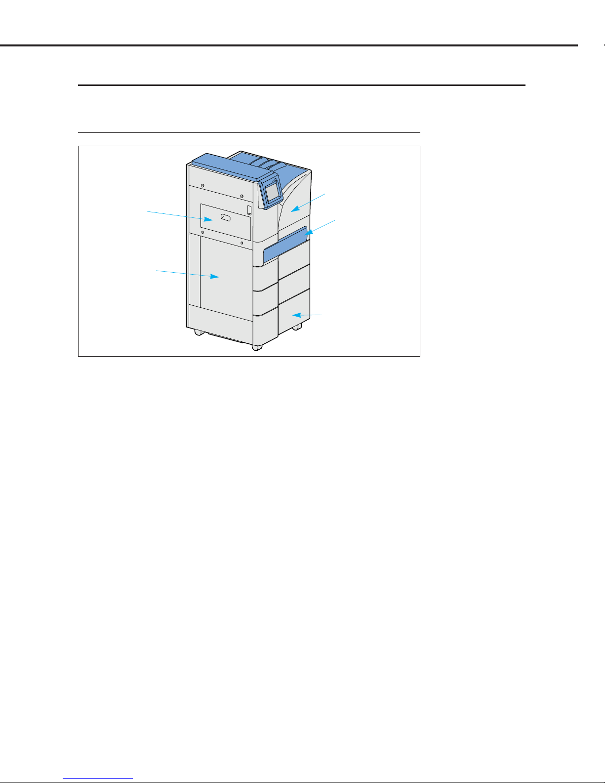
1.4 Part Names
DRYPRO 793 Part names required for installation are detailed below.
1.4.1 Front, Top and Left Sides
1) Front Upper Cover
3) Front Lower Cover
2) Supply Tray 1
4) Exit Cover
5) Left Cover
1) Front Upper Cover
When a film jam occurs I the HPRO
(heat processing unit)/cooling unit, open
this cover to remove the jammed film.
This cover is also opened to replace the
deodorant filter.
2) Supply Tray 1
(Standard: 1 tray, with option: 3 trays)
Film is loaded in these trays.
3) Front Lower Cover
When a film jam occurs in the descent
or elevator transport units or the film
justification unit, this cover may be
opened to remove the jammed film. It is
also possible to access the film from
this opening and feed it through to the
left or right covers.
4) Exit Cover
When a film jam occurs in the ejection
unit, this cover may be opened to
remove the jammed film.
5) Left Cover
When a film jam occurs in the descent
transport unit, this cover may be opened
to remove the jammed film.
This cover may also be removed to
carry out cleaning of the cleaning roller.
Ch.1 Pre-installation Information
< 24 >
DRYPRO Vstage MODEL 793 Installation Manual Ver.1.00 2004.11
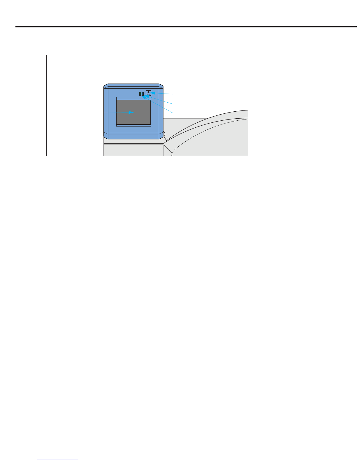
1) Operation Panel
Operates and performs various setting for DRYPRO 793. Also displays various
messages.
2) Operation Button
Starts up or shuts down DRYPRO 793.
3) Operation Lamp
Operating : Constant blue
Start Timer ON : Constant blue
Shutdown Processing : Flashing blue
Power OFF (breaker ON) : Constant Orange
Power OFF (breaker OFF) : Extinguished.
4) Timer Lamp (Green)
Illuminates when the start timer is ON.
1.4.2 Operation Panel
2) Operation Button
3) Operation Lamp
4) Timer Lamp
1) Operation Panel
Ch.1 Pre-installation Information
< 25 >
DRYPRO Vstage MODEL 793 Installation Manual Ver.1.00 2004.11
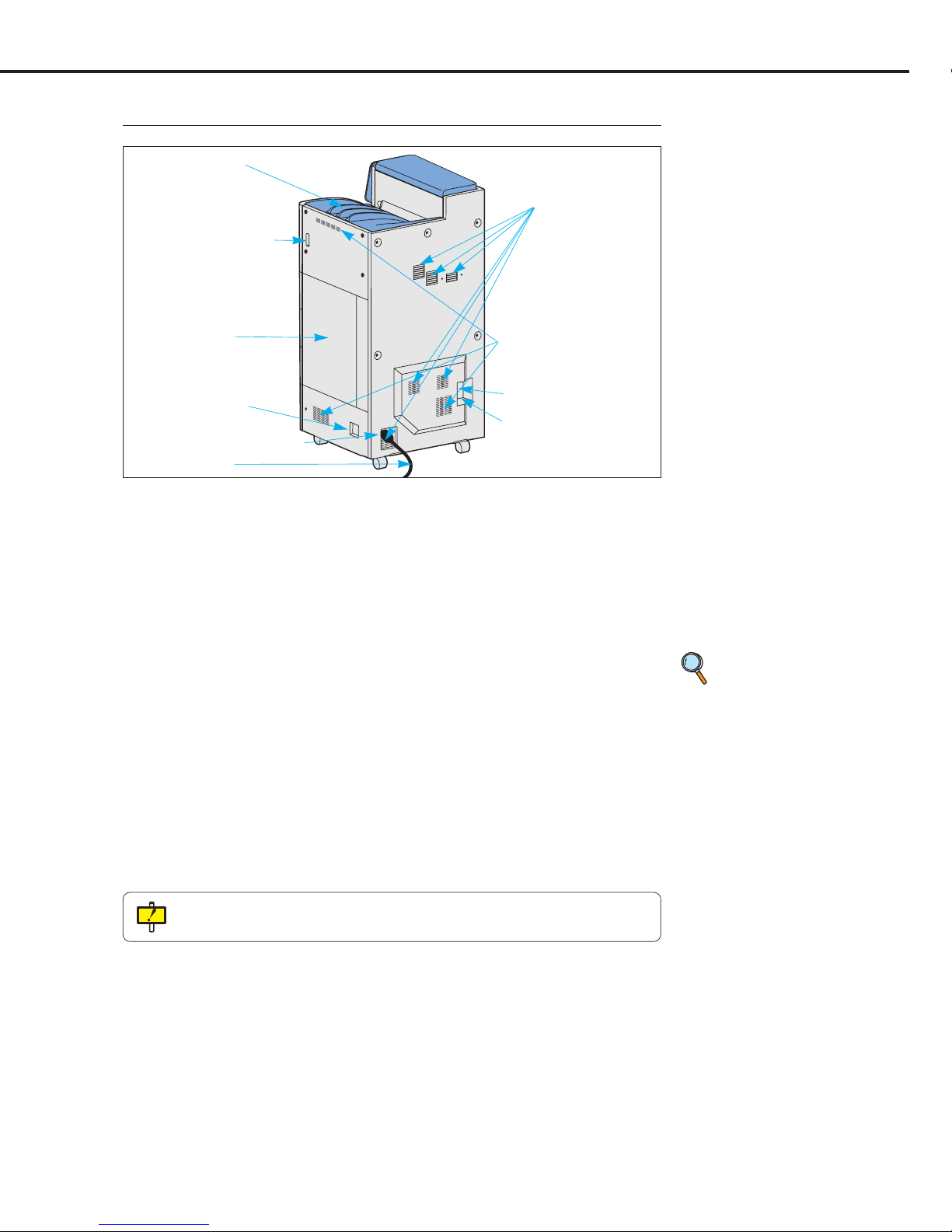
1.4.3 Rear and Right Sides
p.24 Ethernet Port
LEDs
6) Power Cable
7) Outlet
9) Ethernet Port
5) Power Cable Connector
1) Film Exit Tray
Printed films are output to this tray.
When an optional 6ch sorter is installed,
films are output to the sorter.
2) Front Upper Cover Release Lever
Releases the front upper cover lock
when it is necessary to open the cover.
3) Right Cover
When a film jam occurs in the elevator
transport unit, this cover may be opened
to remove the jammed film.
4) Power Breaker
Turns ON/OFF main power.
5) Power Cable Connector
Connects the power cable.
6) Power Cable
Connects DRYPRO 793 to the facility
power outlet.
7) Outlet (4 locations)
Air used to cool the inside of the unit is
released from these ports.
8) Inlet
(2 on the right side, 1 on the rear side)
Takes in air to cool the inside of the
unit.
9) Ethernet Port
Provides connection to the network.
10) Serial Port
The cable from the backup battery, if
used, is connected to this port.
10) Serial Port
8) Inlet
4) Power Breaker
3) Right Cover
2) Front Upper Cover
Release Lever
1) Film Exit Tray
Do not leave films equivalent to one package (= 125 sheets) or more on the Film Exit
Tray.
Ch.1 Pre-installation Information
< 26 >
DRYPRO Vstage MODEL 793 Installation Manual Ver.1.00 2004.11
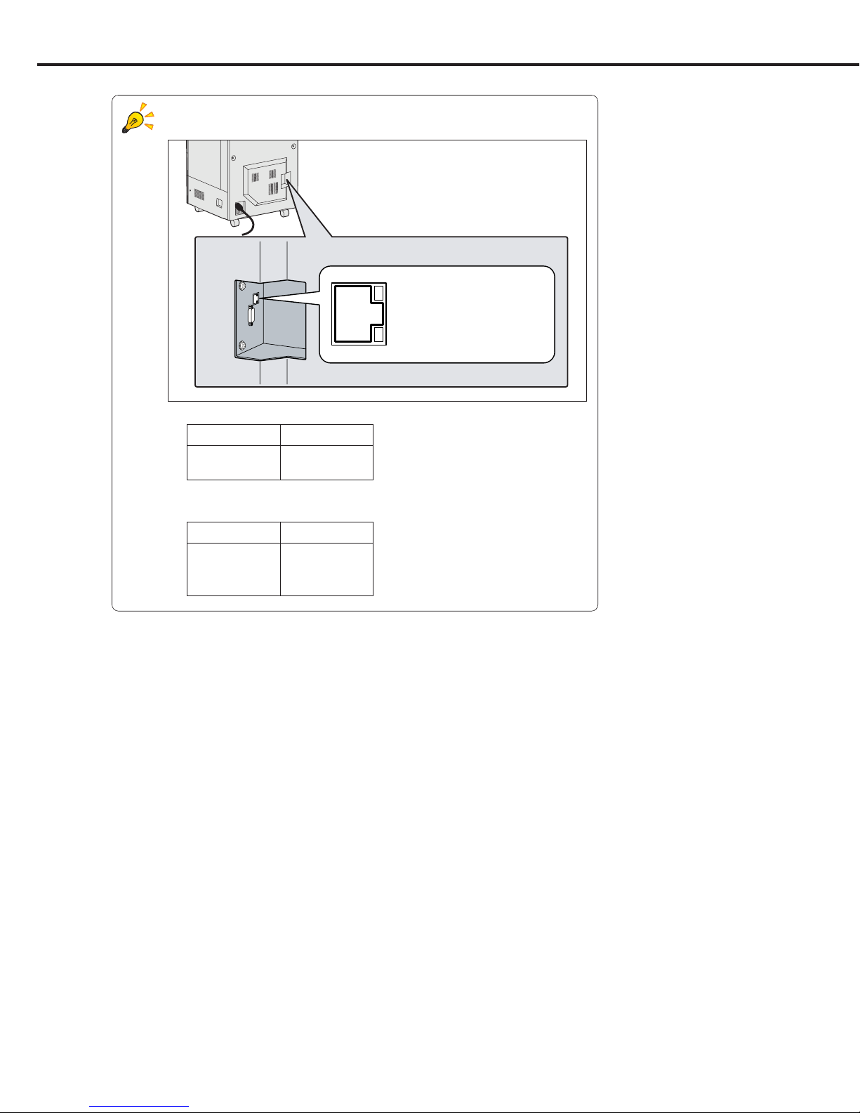
LEDs at the Ethernet Port
Two LEDs at the Ethernet port indicate the following.
- Link/Activity LED
- Com. Speed LED
Com. Status LED
10Mbps Extinguished
100Mbps Constant orange
1000Mbps Constant green
Com. Status LED
Link Constant orange
Activity Constant green
Link / Activity LED
Com. Speed LED
Lower right of the rear side
 Loading...