

Konica Minolta DR1600, DR1600MKII Operator's Manual

WARNING
This equipment has been tested and found to comply with the limits for a Class A digital
device, pursuant to Part 15 of the FCC Rules.
These limits are designed to provide reasonable protection against harmful
interference when the equipment generates, uses, and can radiate radio frequency
energy and, if not installed and used in accordance with the instruction manual, may
cause harmful interference to radio communications. Operation of this equipment in a
residential area is likely to cause harmful interference in which case the user will be
required to correct the interference at his own expense.
The design and production of this unit conform to FCC regulations, and any changes
or modifications must be registered with the FCC and are subject to FCC control. Any
changes made by the purchaser or user without first contacting the manufacture will
be subject to penalty under FCC regulations.

Installation and Operation Precautions
Safety Information
This section contains detailed instructions on the operation and maintenance of this machine. To achieve
optimum utility of this device, all operators should carefully read and follow the instructions in this manual.
Please read the following section before connecting the machine to the supply. It contains important information related to user safety and preventing equipment problems.
Please keep this manual in a handy place near the machine.
Make sure you observe all of the precautions appear in each section of this manual.
KM_Ver.01E_C
2
Note
Some parts of the contents of this section may not correspond with the purchased product.
Warning and Precaution Symbols
The following indicators are used on the warning labels or in this manual to categorize the level of safety
warnings.
WARNING
CAUTION
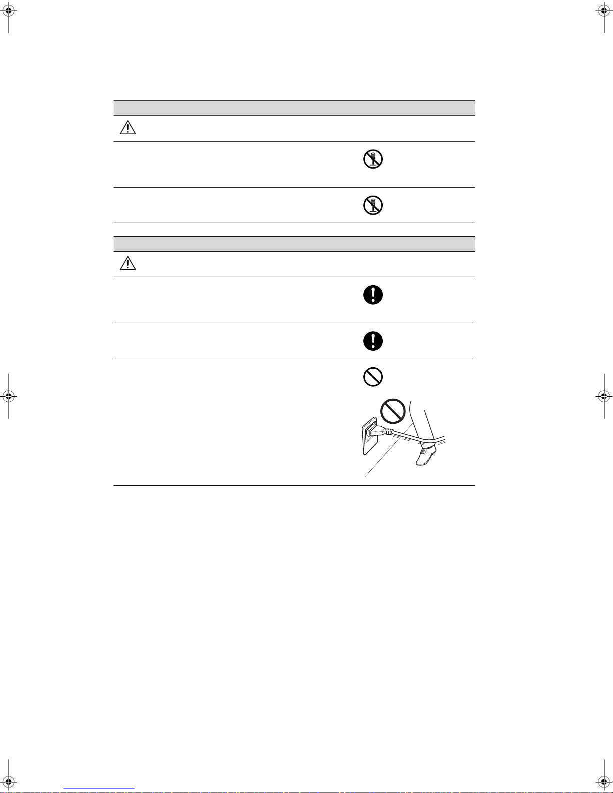
Meaning of Symbols
A triangle indicates a danger against which you should take precaution.
This symbol warns against cause burns.
A diagonal line indicates a prohibited course of action.
This symbol warns against dismantling the device.
A solid circle indicates an imperative course of action.
This symbol indicates you must unplug the device.
Ignoring this warning could cause serious injury or even death.
Ignoring this caution could cause injury or damage to property.
Disassemble and modification
WARNING
• Do not attempt to remove the covers and panels which have
been fixed to the product. Some products have a high-voltage part or a laser beam source inside that could cause an
electrical shock or blindness.
• Do not modify this product, as a fire, electrical shock, or
breakdown could result. If the product employs a laser, the
laser beam source could cause blindness.
Power cord
WARNING
• Use only the power cord supplied in the package. If a power
cord is not supplied, only use the power cord and plug that
is specified in POWER CORD INSTRUCTION. Failure to use
this cord could result in a fire or electrical shock.
• Use the power cord supplied in the package only for this machine and NEVER use it for any other product. Failure to observe this precaution could result in a fire or electrical shock.
• Do not scratch, abrade, place a heavy object on, heat, twist,
bend, pull on, or damage the power cord. Use of a damaged
power cord (exposed core wire, broken wire, etc.) could result in a fire or breakdown.
Should any of these conditions be found, immediately turn
OFF the power switch, unplug the power cord from the power outlet, and then call your authorized service representative.
Power source
WARNING
• Use only the specified power source voltage. Failure to do
that could result in a fire or electrical shock.
• Connect power plug directly into wall outlet having the same
configuration as the plug. Use of an adapter leads to the
product connecting to inadequate power supply (voltage,
current capacity, grounding), and may result in fire or shock.
If proper wall outlet is not available, the customer shall ask
qualified electrician for the installation.
• Do not use a multiple outlet adapter nor an extension cord in
principle. Use of an adapter or an extension cord could
cause a fire or electrical shock.
Contact your authorized service representative if an extension cord is required.
• Consult your authorized service representative before connecting other equipment on the same wall outlet. Overload
could result in a fire.
CAUTION
• The outlet must be near the equipment and easily accessible. Otherwise you can not pull out the power plug when an
emergency occurs.
Power plug
WARNING
• Do not unplug and plug in the power cord with a wet hand,
as an electrical shock could result.
• Plug the power cord all the way into the power outlet. Failure
to do this could result in a fire or electrical shock.
CAUTION
• Do not tug the power cord when unplugging. Pulling on the
power cord could damage the cord, resulting in a fire or
electrical shock.
• Remove the power plug from the outlet more than one time
a year and clean the area between the plug terminals. Dust
that accumulates between the plug terminals may cause a
fire.
Grounding
WARNING
• Connect the power cord to an electrical outlet that is
equipped with a grounding terminal.
Installation
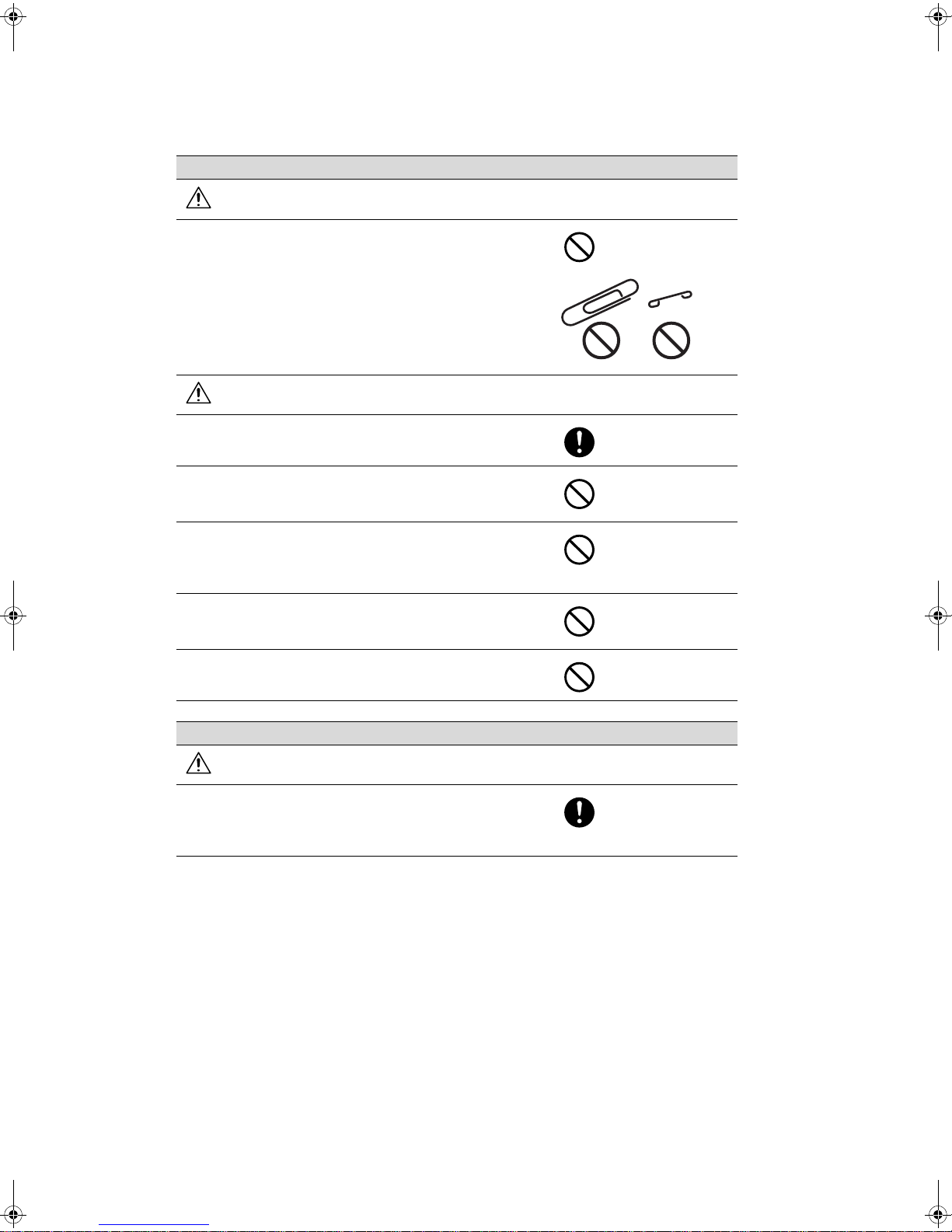
WARNING
• Do not place a flower vase or other container that contains
water, or metal clips or other small metallic objects on this
product. Spilled water or metallic objects dropped inside the
product could result in a fire, electrical shock, or breakdown.
Should a piece of metal, water, or any other similar foreign
matter get inside the product, immediately turn OFF the
power switch, unplug the power cord from the power outlet,
and then call your authorized service representative.
CAUTION
• After installing this product, mount it on a secure base. If the
unit moves or falls, it may cause personal injury.
• Do not place the product in a dusty place, or a site exposed
to soot or steam, near a kitchen table, bath, or a humidifier.
A fire, electrical shock, or breakdown could result.
• Do not place this product on an unstable or tilted bench, or
in a location subject to a lot of vibration and shock. It could
drop or fall, causing personal injury or mechanical breakdown.
• Do not let any object plug the ventilation holes of this product. Heat could accumulate inside the product, resulting in a
fire or malfunction.
• Do not use flammable sprays, liquids, or gases near this
product, as a fire could result.
Ventilation
CAUTION
• Always use this product in a well ventilated location. Operating the product in a poorly ventilated room for an extended
period of time could injure your health. Ventilate the room at
regular intervals.
Actions in response to troubles
WARNING
• Do not keep using this product, if this product becomes inordinately hot or emits smoke, or unusual odor or noise. Immediately turn OFF the power switch, unplug the power cord
from the power outlet, and then call your authorized service
representative. If you keep on using it as is, a fire or electrical
shock could result.
• Do not keep using this product, if this product has been
dropped or its cover damaged. Immediately turn OFF the
power switch, unplug the power cord from the power outlet,
and then call your authorized service representative. If you
keep on using it as is, a fire or electrical shock could result.
When moving the machine
CAUTION
• Whenever moving this product, be sure to disconnect the
power cord and other cables. Failure to do this could damage the cord or cable, resulting in a fire, electrical shock, or
breakdown.
• When moving this product, always hold it by the locations
specified in the User’s Guide or other documents. If the unit
falls it may cause severe personal injury. The product may
also be damaged or malfunction.
Before successive holidays
CAUTION
• Unplug the product when you will not use the product for
long periods of time.

CONTENTS
SPECIFICATIONS................................................................................................ 1
INSTALLATION .................................................................................................... 2
PARTS IDENTIFICATION .................................................................................... 4
CONTROL PANEL KEYS AND INDICATORS ..................................................... 6
REMOVING AND INSTALLING THE FILM UNIT ................................................. 8
FILMING PROCEDURE ....................................................................................... 9
LOADING AND UNLOADING FILM ................................................................... 10
SPACING............................................................................................................ 14
RELATIONSHIP BETWEEN DOCUMENT SIZE AND MAGNIFICATION.......... 15
TAKING A STEP TEST ...................................................................................... 16
MICROFILMING ................................................................................................. 17
RECORDING DOCUMENT MARK..................................................................... 18
RECORDING FRAME NUMBER........................................................................ 20
MANUAL EXPOSURE MODE ............................................................................ 22
CHOICE MODES................................................................................................ 23
MAINTENANCE AND SERVICES...................................................................... 27
POTENTIAL PROBLEMS................................................................................... 29
TROUBLESHOOTING........................................................................................ 30
SUPPLEMENT ................................................................................................... 31

SPECIFICATIONS
■ Type: : Planetary Microfilmer
■ Lens: : Micro-Rokkor f = 28 mm
■ Film: : 16-mm Roll Film (Non-Perforated)
5 mil - 100 ft., 2.5 mil - 215 ft.
■ Document Size: : Max. 17” x 11” or A3
■ Frame (Aperture) Size: : Single - 9.7 x 12.6 mm
Double - 18.2 x 12.6 mm
Automatically selected according to the original size detected, or manually selected.
■ Pulldown: : Single - 10.0 mm (9.5 to 11.75 mm)
Double - 18.5 mm (18.0 to 23.5 mm)
■ Spacing: : Single Frame, Prefixed Frames (5 to 250 frames) and Any Desired Frames
(1 to 9999 frames)
■ Resolution: : 150 lines or more/mm
■ Depth of Field: : +20 mm from Copy Board
■ Reduction Ratios: : 1/25 (Single and Double Frames)
1/32 (Single Frame)
■ Numbering: : 12 digits (4 digits x 3 fields)
• Used for the block, batch, and item numbers.
• Can also be used as an 8- or 4-digit counter.
■ Document Marks: : Three document mark levels
Tri level (L, M, S)
Dual level (L, S)
Single level (L or M or S)
■ Document Mark : Document Mark Positioning of the medium width Single Level Mark can be adjusted
Positioning: by using choice Mode (between 1.21 to 4.21 mm).
■ Film Supply Warning: : Beeping warns that the film will soon be running out and a warning Light indicates
the length of film remaining for use reaches approx. 1.5 meters. (5 ft.)
■ Exposure Control: : Automatic and Manual exposure control
■ Light Source: : Two 15-W fluorescent lamps
■ Power Requirement: : 120 V 60 Hz, 220/230 - 240 V 50 Hz
■ Power Consumption: : 100W
■ Dimensions: : 900 (W) x 700 (D) x 1250 (H) mm or 35-7/16” (W) x 27-9/16” (D) x 49-7/32” (H)
■ Weight: : 41 kg or 90 lbs
■ Options: : Foot Pedal, Black Board, Resettable Counter (6-digit), RS232C Interface Kit
■ Accessory: : Blower Brush, Reel
CAUTION
Use a shielded cable for the RS-232C interface cable.
Specification of this equipment are subject to change without notice.
.
1
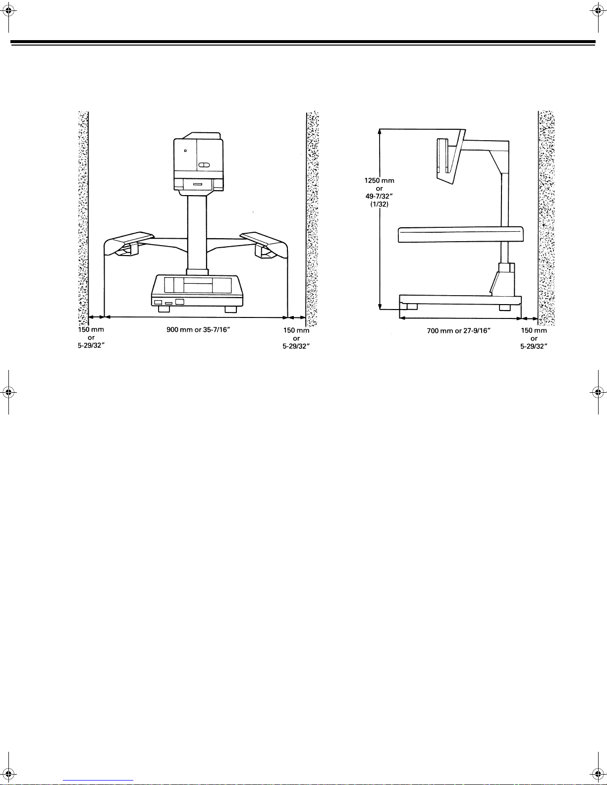
INSTALLATION
■ INSTALLATION
■ Space Requirements
To ensure easy operation and service the machine requires the following installation space.
2
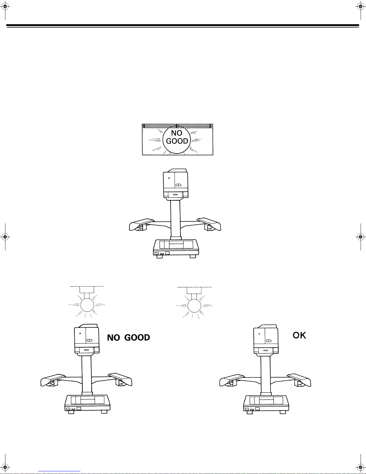
■ Installation Site
To prevent the machine from developing malfunction and to ensure its best possible performance, avoid
installing the machine in a place:
• Which is exposed to direct sunlight.
• Which is immediately under a light.
• Which is near a bright window.
• Which is in the direct air stream of an air conditioner or ventilator.
• Which is subject to vibrations.
• Which is dusty.
• Which is tilted place 1°
3
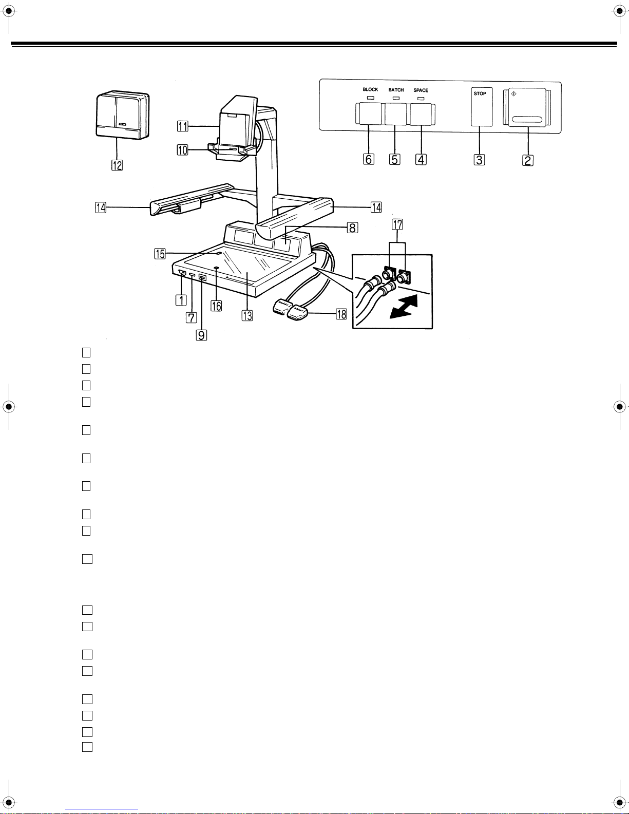
PARTS IDENTIFICATION
■ PARTS IDENTIFICATION
1
Power ON/OFF Switch: Used to turn ON and OFF the machine.
2
Shutter Button: Press this Button to make an exposure, advancing film to the next frame.
3
Stop Key: Press this Key to stop advancing the film or beeps sounding.
4
Spacing Key: Press and release this Key to skip one frame between images without
exposure. Holding it down will advance the film continuously.
5
Batch Key: Press this Key to allow for generating a large document mark in dual-level
recording or a medium document mark in tri-level recording.
6
Block Key: Press this Key to allow for generating a large document mark in tri-level
recording.
7
Total Counter (7-digit): Incremented by one each time the Shutter Button is pressed, showing a
running count of frame exposures.
8
Control Panel: See page 6.
9
Resettable Counter (6-digit) Incremented by one each time the Shutter Button is pressed. It can be
[Option] : reset to 0.
10
Film Unit Release Lever: Place this Lever in the left position before attempting to remove the Film
Unit from the machine, which cuts off power supply to the Film Unit.
Place the Lever in the right position after reinstalling the Film Unit to the
machine.
11
Film Unit Mounting Board: Serves as a base to hold the Film Unit in position.
12
Film Unit: Photographs the document and produces a document mark and frame
number on the film.
13
Copy Board: Serves as the surface on which the documents are placed.
14
Lamp Unit: Holds two 15-W fluorescent lamps to illuminate the document on the Copy
Board.
15
Reduction Ratio Detecting Sensor: Detects the width of the document to determine the reduction ratio.
16
Frame Size Detecting Sensor: Detects the length of the document to determine the frame size.
17
Foot Pedal Connector [Option] : Connect the Foot Pedals.
18
Foot Pedal [Option] :
4
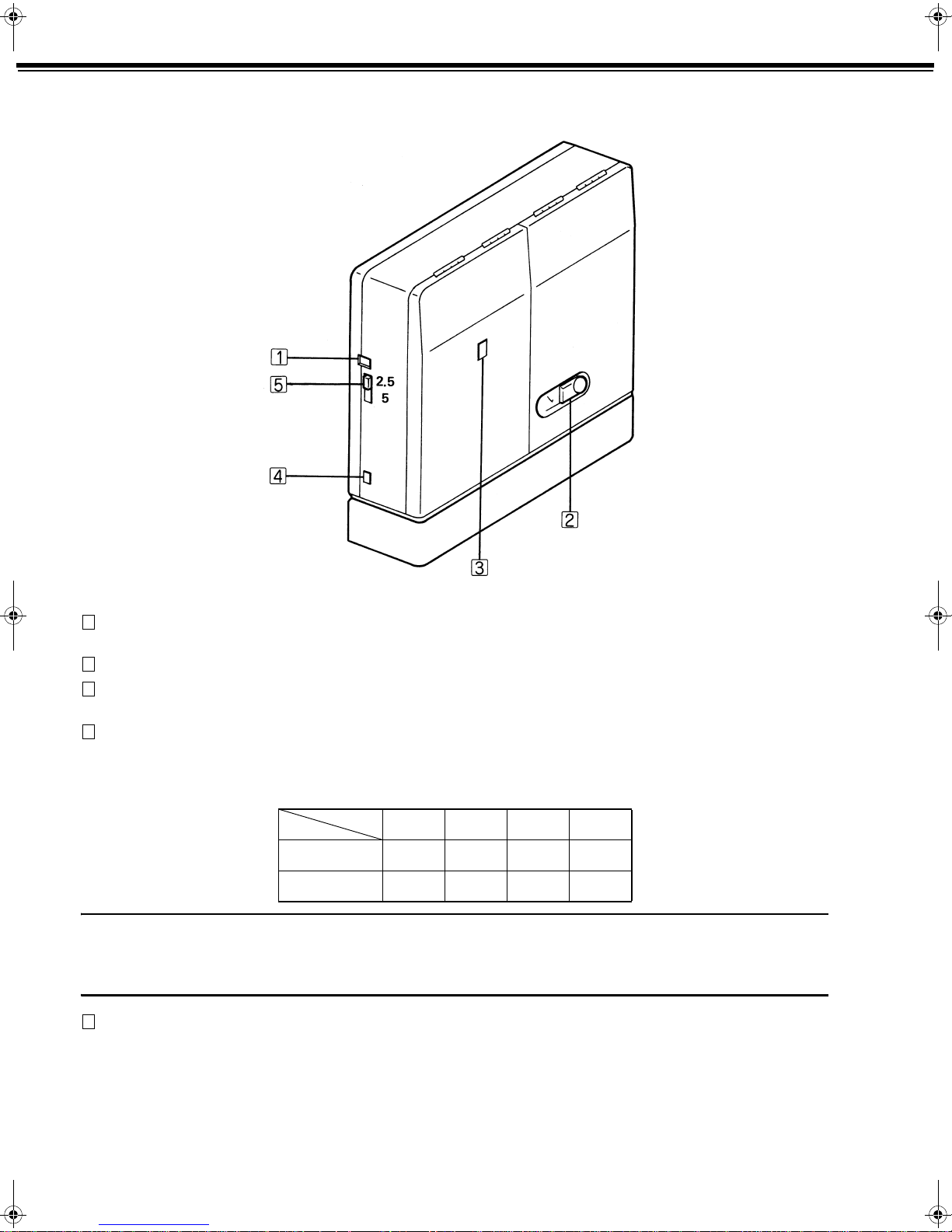
■ FILM UNIT
1
Film Supply Indicator Displays the length of usable, unexposed film left in the Film Unit in
(2.5 mil, 5 mil): meters or feet.
2
Film Door Lock: Locks and unlocks the Film Take-Up Door.
3
Film Movement Indicator: The stripes in the window move while the film is being advanced during
filming.
4
Memory Switches: Allow for storing in machine memory the last frame number used with a
particular Film Unit. Each DR1600MKII machine can control up to four
different Film Units.
1234
Switch 1 ON ON OFF OFF
Switch 2 OFF ON ON OFF
NOTE
If the Memory Switch positions are changed during microfilming or with the Film Unit removed, the machine
memory is unable to keep track of the correct data. Be sure, therefore, to make the switch settings when a fresh film
is loaded in the Film Unit.
5
Film Thickness Select Switch: Used to select the film thickness, either 2.5 mil or 5 mil, according to the
film being used.
5
 Loading...