

KONICA MINOLTA Disassem Service Manual

1156SBD000AA
EP5000/EP4000
DIS/REASSEMBLY,
ADJUSTMENT
1151SBD0000A
u For the Utmost safety u
Warning
!
DForreplacementparts,usethegenuinepartswiththeir part numbers specified in the parts manual. Use
of a wrong part could cause an overload or dielectric breakdown resulting in an electric shock or fire.
DReplacea blown fuse or thermalfuse with the correspondinggenuine part with itspart number specified
in the parts manual. Use of a fuse with a different rating or one with the same rating but of a different
type can result in a fire.
Especially when a thermal fuse blows frequently, the thermal control system is probably faulty.
Be sure to take necessary action.
DBeforeattempting to disassemble the machine,besure to unplug its power cord.Themachinecontains
a high voltageunit and acircuit with a large current capacity that may cause an electric shock or burn
from sparking.
The machine also contains quick moving parts, which could injure a person.
If the machine uses a laser, a person can lose his/her eyesight by a laser beam leak.
DWherever feasible, keep the covers and parts mounted when energizing the machine.
If it isabsolutely necessary toenergize the machine with its cover removed, do not touch an exposed
part that is being charged and use care not to allow your clothing to be caught by a timing belt, gear,
or other moving part.
DDo not leave the machine unattended while it is being energized.
Caution
!
DToactuateaninterlockswitchwithacoverremovedoropened, be sure to use the interlock switch actu-
ating jig. Use of folded paper can damage the interlock switch mechanism.
i
Caution
!
DA high voltage is being applied to the part marked with the symbol shown
on the right. Touching it can cause an electric shock. Be sure to unplug the
power cord when servicing this part or other parts near it.
DWhen the machine is energized with any of its covers removed, never use a flammable spray nearit,
as a fire can result.
DMake sure thatcorrect screws (diameterand length of the screw,binding/tapping screws) are used in
the correct places when assembling parts. If a wrong screw is used,a short insulating distance could
result.It could also result incollapsedthreads, which providesonlya poor groundingconnection,resulting in an electric shock.
DAtoothedwasherandspringwasher,if used originally,must be reinstalled. If they are left out, a contact
failure results, causing an electric shock or fire.
DReplace a lithium cell only with one having the part numberspecified in the parts manual. Anexplosion
could result if the cell is installed with wrong polarity or a wrong cell is installed.
Disposeof a used lithium cellaccordingto the applicablelocalregulations. Never throwitaway or abandon it on the user’s premises.
u Other Precautions u
DWhile the machine is being energized, do not unplug or plug in a connector on a PWB or relay harness.
DSincethe Magnet Roller of theImagingUnit generates a strongmagneticforce, do notbringa CRT,watch,
floppy disk, or magnetic card near it.
DUseof an airgunor vacuum generatesstaticelectricity which cancausethe ATDCSensor andassociated
parts to break down. Be sure therefore to use a blower brush or cloth to clean these parts. If a unit is to
be cleaned, be sure to remove the sensors in advance.
DMOS lCs are susceptible to static electricity.When handling a PWB loaded with MOSICs, followprecau-
tions given in “INSTRUCTIONS FOR HANDLING THE PWBs WITH MOS ICs.”
DThePC Drum is highly delicate.Whenhandling the PC Drum, followtheprecautionsgiven in “HANDLING
OF THE PC DRUM.”
DTo reassemble, reverse the order of disassembly unless otherwise specified.
DNote that replacement of a PWB may call for readjustments or resetting of particular items.
CAUTION: DANGER OF EXPLOSION IF BATTERY IS INCORRECTLY REPLACED. REPLACE
ONLYWITH THE SAME OR EQUIVALENT TYPE RECOMMENDED BY THE MANUFACTURER.
DISPOSE OF USED BATTERIES ACCORDING TO THE MANUFACTURER’S INSTRUCTIONS.
ADVARSEL!:Lithiumbatteri- Eksplosionsfare ved fejlagtig håndtering. Udskiftning må kun ske med
batteri af samme fabrikat og type. Levér det brugle bafferi tilbage til leverandoren.
ii

1156SBD000BA
CONTENTS
SERVICE INSTRUCTIONS1
1-1. PRECAUTIONS FOR DISASSEMBLY/ADJUSTMENTS D-1......
1-2. INSTRUCTIONS FOR HANDLING THE PWBs
WITH MOS ICs D-3.........................................
1-3. HANDLING OF THE PC DRUM D-3...........................
1-4. PARTS WHICH MUST NOT BE TOUCHED D-5.................
DISASSEMBLY/REASSEMBLY2
2-1. DOORS, COVERS, AND EXTERIOR PARTS:
IDENTIFICATION AND REMOVAL PROCEDURES D-6..........
2-2. REMOVAL OF CIRCUIT BOARDS D-8........................
2-3. PAPER TAKE-UP/TRANSPORT SECTIONS D-10...............
(1) Removal of the Paper Take-Up Unit D-10....................
(2) Removal of the Paper Take-Up Roll/Feed Roll Assy and
Separator Roll Assy D-13.................................
(3) Cleaning of the Paper Take-Up Roll, Feed Roll,
and Separator Roll D-16..................................
(4) Cleaning of the Vertical Transport Rollers D-17...............
(5) Removal of the Drawers D-17..............................
(6) Removal of the Upper Synchronizing Roller D-19.............
(7) Cleaning of the Upper and Lower Synchronizing
Rollers D-20.............................................
(8) Replacement of the Paper Dust Remover D-20...............
(9) Cleaning of the Paper Dust Remover D-21...................
(10) Removal of the Suction Unit D-22.........................
(11) Disassembly of the Suction Unit D-23......................
(12) Disassembly of the Multi Bypass Unit D-24.................
2-4. OPTICAL SECTION D-28....................................
(1) Cleaning of the Original Glass D-28.........................
(2) Cleaning of the Scanner Shaft D-28........................
(3) Cleaning of the Scanner Rail D-28..........................
(4) Removal of the Scanner D-29..............................
(5) Cleaning of the Exposure Lamp D-29.......................
(6) Removal of the Thermal Fuse D-30.........................
(7) Cleaning of the 1st, 2nd, and 3rd Mirrors D-30...............
(8) Cleaning of the Lens and 4th and 5th Mirrors D-31............
(9) Winding of the Lens Drive Cable D-32......................
(10) Removal of Scanner Motor M2 D-34.......................
(11) Removal of the Scanner Drive Cable D-35..................
(12) Winding of the Scanner Drive Cable D-36..................
(13) Cleaning of the 6th Mirror Protective Filter D-37.............
(14) Cleaning of the Cooling Fan Filter D-37....................
iii

CONTENTS
2-5. IMAGING UNIT D-38........................................
(1) Removal of the Imaging Unit D-38..........................
(2) Disassembly of the Imaging Unit D-38......................
(3) Replacement of the PC Drum D-42.........................
(4) Cleaning of the Developer Scattering Prevention Plate D-42...
(5) Cleaning of the Ds Positioning Collars D-42..................
(6) Cleaning of the Toner Antispill Trap D-42....................
(7) Cleaning of the Cleaning Blade D-42........................
(8) Replacement of the Cleaning Blade D-43....................
(9) Replacement of the Starter D-45...........................
(10) Cleaning of the AIDC Sensor Board D-46..................
(11) Cleaning of the PC Drum Paper Separator Fingers D-46.....
(12) Replacement and Cleaning of the Toner Antispill Seal
and Cleaning of the Toner Antispill Plate D-46................
(13) Removal of Main Erase Lamp LA3 D-47....................
(14) Cleaning of the Main Erase Lamp Filter D-47...............
(15) Cleaning of Image Erase Lamp LA2 D-47..................
(16) Replacement of Image Erase Lamp LA2 D-47..............
(17) Removal of the Ozone Filter
(PC Drum Charge Corona) D-48..........................
(18) Removal of the Ozone Filter
(Image Transfer/Paper Separator Coronas) D-48............
(19) Removal of the Toner Collecting Box D-48..................
2-6. PC DRUM CHARGE CORONA AND
IMAGE TRANSFER/PAPER SEPARATOR CORONAS D-49......
(1) Removal of the PC Drum Charge Corona D-49...............
(2) Cleaning of the PC Drum Charge Corona Housing D-49.......
(3) Cleaning of the PC Drum Charge Corona Grid Mesh D-50.....
(4) Cleaning of the Comb Electrode D-50.......................
(5) Removal of the Image Transfer/Paper Separator
Coronas D-50...........................................
(6) Cleaning and Replacement of the Image Transfer
Corona Wire D-50........................................
(7) Cleaning and Replacement of the Paper Separator
Corona Wire D-51........................................
(8) Cleaning of the Image Transfer/Paper Separator
Coronas Housing D-51....................................
(9) Cleaning of the Lower Pre-Image Transfer
Guide Plate D-52.........................................
2-7. FUSING UNIT D-53.........................................
(1) Removal of the Fusing Unit D-53...........................
(2) Disassembly of the Fusing Unit D-53........................
(3) Replacement and Cleaning of the Upper Fusing Paper
Separator Fingers D-58...................................
(4) Cleaning of the Lower Fusing Paper Separator Fingers D-58...
(5) Cleaning of the Fusing Unit Entrance Guide Plate D-58........
iv

CONTENTS
(6) Cleaning of Fusing Front and Rear Thermistors TH1/2 D-58....
(7) Cleaning of Fusing Thermoswitch TS1 D-59.................
(8) Replacement and Cleaning of the Cleaning Roller D-59.......
(9) Replacement and Cleaning of the Upper Fusing
Roller D-59..............................................
(10) Replacement and Cleaning of the Lower Fusing
Roller D-60.............................................
2-8. EXIT UNIT D-61............................................
(1) Removal of the Exit/Duplex Switching Unit D-61..............
ADJUSTMENT3
3-1. JIGS AND TOOLS USED D-62...............................
3-2. ADJUSTMENT REQUIREMENTS LIST D-63...................
3-3. ADJUSTMENT OF SWITCHES D-64..........................
Adjustment of Front Door Interlock Switch S21 D-65.............
3-4. ADJUSTMENT OF BELT TENSION D-66......................
(1) Paper Take-Up Unit Timing Belt D-66.......................
(2) Developing Unit Timing Belt D-66...........................
(3) Fusing Unit Timing Belt D-66...............................
(4) I/U Timing Belt D-66......................................
3-5. ACCESSING THE TECH. REP. MODE AND
ADJUST MODE D-67.......................................
3-6. ELECTRICAL/IMAGE ADJUSTMENTS D-68...................
(1) Initial Adjustment of Original Size Detecting Board D-68.......
(2) ATDC Adjustment D-69...................................
(3) Adjustment of the Aperture Blades D-71.....................
(4) Adjustment of Exposure Level in the Auto
Exposure Mode D-72.....................................
(5) Adjustment of Optimum Exposure Setting in the Manual
Exposure Mode D-73.....................................
(6) Adjustment of Zoom Ratio in the Crosswise Direction D-75.....
(7) Adjustment of Zoom Ratio in the Feeding Direction D-77......
(8) Adjustment of Reference Position of the Multi
Bypass Table D-79.......................................
(9) Adjustment of Reference Position of the 1st/2nd
Drawer D-80.............................................
(10) Adjustment of the Leading Edge Registration D-81..........
(1)Leading Edge Registration in Full Size Mode D-81........
(2)Leading Edge Registration in Enlargement Mode D-83....
(3)Leading Edge Registration in Reduction Mode D-85.......
(11) Adjustment of the Leading Edge Registration for Book
Second Page D-87......................................
(12) Adjustment of the Image Leading Edge Erase Width D-89....
(13) Adjustment of the Image Trailing Edge Erase Width D-91.....
(14) Adjustment of Edge Erase D-93...........................
v

CONTENTS
3-7. OTHER ADJUSTMENTS D-94...............................
(1) Focus-Positioning of the Scanner and Mirrors
Carriage D-94...........................................
(2) Adjustment of the Gap Between the Doctor Blade and
Sleeve Roller (D.B. Adjustment) D-96.......................
(3) Adjustment of the PC Drum Paper Separator Finger
Position D-97............................................
(4) Adjustment of Manual Feed Paper Take-Up Solenoid
SL4 D-98..............................................
(5) Adjustment of Exit/Duplex Solenoid SL5 D-99................
MISCELLANEOUS4
4-1. INSTALLATION OF THE PLUG-IN COUNTER (OPTION)
MOUNTING BRACKET D-100................................
4-2. ADJUSTMENT OF THE RIGHT DOOR D-101..................
vi

1139SBD0100A
SERVICE INSTRUCTIONS1
1151SBD0101B
1-1. PRECAUTIONS FOR DISASSEMBLY/ADJUSTMENTS
Observe the following precautions whenever servicing the copier.
Be sure to unplug the copier from the outlet before attempting to service the copier.
D
The basic rule is not to operate the copier anytime during disassembly.
D
If it is absolutely necessary to run the copier with its covers removed, use care not to allow your clothing
to be caught in revolving parts such as the timing belt and gears.
Be sure to use the Interlock Switch Actuating Jig whenever it is necessary to actuate the Interlock Switch
D
with the covers left open or removed.
Do not plug in or unplug print jacks on the Board or connect or disconnect the Board connectors while
D
power is being supplied to the copier.
Do not use flammable spray around the copier in operation.
D
The Magnet Roller of the Imaging Unit generates strong magnetic force. Do not bring it near a cathode-ray
D
tube or watch.
The lithium cell in RAM Board PWB-R can burst. At replacement, make sure of the correct polarity and
D
do not change it or create a closed circuit.
A used lithium cell should be disposed of according to the local regulations and never be discarded casually or left unattended at the user’s premises.
Do not use an air gun or vacuum cleaner for cleaning the ATDC Sensor and other sensors, as they can
D
cause electrostatic destruction. Use a blower brush and cloth. If a unit containing these sensors is to be
cleaned, first remove the sensors from the unit.
When handling the PWBs with MOS ICs, observe “Instructions for Handling the PWBs with MOS ICs.”
D
When handling the PC Drum, observe precautions given in “Handling of the PC Drum.”
D
Note that replacement of a PWB may call for readjustments or resetting of particular items.
D
Use the right screw in the right place at reassembly. Note that some are longer and some are thicker than
D
others.
A toothed washer is used with the screw that secures the ground wire to ensure positive conduction. Do
D
not forget to insert this washer at reassembly.
To reassemble the copier, reverse the order of disassembly unless otherwise specified.
D
If it becomes necessary to replace the thermal fuse or any other fuse mounted on a board, be sure to use
D
one of the rating marked on the blown fuse.
Always note the rating marked on the fuse, as the rating and mounting site or number used are subject
to change without notice.
Do not pull out the TonerHopper while the TonerBottle is turning, as a damaged Toner Replenishing Motor
D
or locking mechanism could result.
If the copier is to be run with the Front Door swung down, make sure that the Toner Hopper is in the locked
position.
CAUTION: DANGER OF EXPLOSION IF BATTERY IS INCORRECTLY REPLACED. REPLACE
ONLY WITH THE SAME OR EQUIVALENT TYPE RECOMMENDED BY THE MANUFACTURER.
DISCARD USED BATTERIES ACCORDING TO THE MANUFACTURER’S INSTRUCTIONS.
D-1
<List of Fuses Used>
Fuse Board
PWB-L 250V 3A (4)
Power Supply Board
PWB-C 250V 3A (5)
Fuse Holder
F3 250V 15A
Exposure Thermal Fuse
TF1 110
C 10A
°°°°
Power Supply Unit
PU1 125V 8A
Noise Filter Board
PWB-D 250V 15A
D-2
1156D001CA

1139SBD0102A
1-2. INSTRUCTIONS FOR HANDLING THE PWBs WITH MOS ICs
The following precautions must be observed when handling P.W. Boards with MOS (Metal Oxide
Semiconductor) ICs.
During Transportation/Storage:
During transportation or when in storage, new P.W. Boards must not be indiscriminately removed from
D
their protective conductive bags.
Do not store or place P.W. Boards in a location exposed to direct sunlight.
D
When it becomes absolutely necessary to remove a Board from its conductive bag or case, always place
D
it on its conductive mat in an area as free as possible from static electricity.
Do not touch the pins of the ICs with your bare hands.
D
During Replacement:
Before unplugging connectors from the P.W. Boards, make sure that the power cord has been unplugged
D
from the outlet.
When removing a Board from its conductive bag or conductive case, do not touch the pins of the ICs or
D
the printed pattern. Place it in position by holding only the edges of the Board.
Before plugging connectors into the Board, make sure that the power cord has been unplugged from the
D
power outlet.
During Inspection:
Avoid checking the IC directly with a multimeter; use connectors on the Board.
D
Never create a closed circuit across IC pins with a metal tool.
D
When it is absolutely necessary to touch the ICs and other electrical components on the Board, be sure
D
to ground your body.
1151SBD0103A
1-3. HANDLING OF THE PC DRUM
During Transportation/Storage:
Use the specified carton whenever moving or storing the PC Drum.
D
The storage temperature is in the range between −20
D
In summer, avoid leaving the PC Drum in a car for a long time.
D
C and +40
°°°°
C.
°°°°
Handling:
Ensure that the correct PC Drum is used.
D
Whenever the PC Drum has been removed from the copier, store it in its container or protect it with a Drum
D
Cloth.
The PC Drum exhibits greatest light fatigue after being exposed to strong light over an extended period
D
of time. Never, therefore, expose it to direct sunlight.
Use care not to contaminate the surface of the PC Drum with oil-base solvent, fingerprints, and other for-
D
eign matter.
Do not scratch the surface of the PC Drum.
D
Do not apply chemicals to the surface of the PC Drum.
D
Do not attempt to wipe clean the surface of the PC Drum.
D
D-3
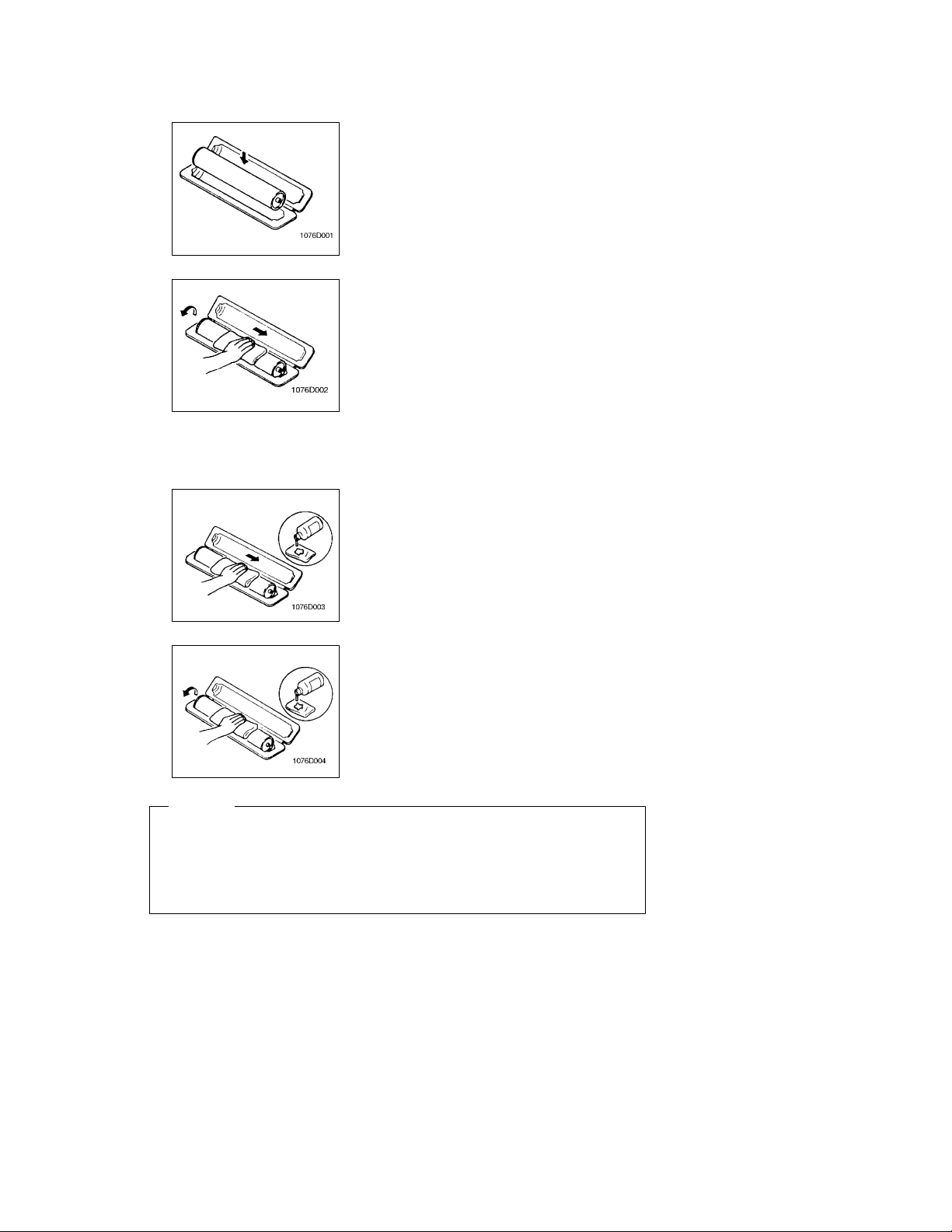
If, however, the surface is contaminated with fingerprints, clean it using the following procedure.
1. Place the PC Drum into one half of its container.
2. Gently wipe the residual toner off the surface of the PC
Drum with a dry, Dust-Free Cotton Pad.
a) Rotate the PC Drum so that the area of its surface on
which the line of toner left by the Cleaning Blade is present is facing straight up. Wipe the surface in one continuous movement from the rear edge of the PC Drum to
the front edge and off the surface of the PC Drum.
b) Rotate the PC Drum slightly and wipe the newly ex-
posed surface area with a CLEAN face of the Dust-Free
Cotton Pad. Repeat this procedure until the entire surface of the PC Drum has been thoroughly cleaned.
* At this time, always use a CLEAN face of the dry Dust-Free
Cotton Pad until no toner is evident on the face of the Pad
after wiping.
3. Soak a small amount of either ethyl alcohol or isopropyl alcohol into a clean, unused Dust-Free Cotton Pad which
has been folded over into quarters. Now, wipe the surface
of the PC Drum in one continuous movement from its rear
edge to its front edge and off its surface one to two times.
* Never move the Pad back and forth.
4. Using the SAME face of the Pad, repeat the procedure explained in the latter half of step 3 until the entire surface of
the PC Drum has been wiped. Always OVERLAP the
areas when wiping. Two complete turns of the PC Drum
would be appropriate for cleaning.
NOTES
D The Organic Photoconductor Drum is softer than CdS and Selenium Drums and is therefore
susceptible to scratches.
D Even when the PC Drum is only locally dirtied, wipe the entire surface.
D Do not expose the PC Drum to direct sunlight. Clean it as quickly as possible even under interior
illumination.
D If dirt remains after cleaning, repeat the entire procedure from the beginning one more time.
D-4
1151SBD0104A
1-4. PARTS WHICH MUST NOT BE TOUCHED
(1) Screws
Purpose of Application of Red Paint
Red paint is applied to the screws which cannot be readjusted, set, or reinstalled in the field.
The basic rule is not to remove or loosen the screws to which red paint is applied. In addition, be advised
that, if two or more screws are designated as those which must not be touched on a single part, only
one representative screw may be marked with red paint.
(2) Variable Resistors on Board
Do not turn the variable resistors on boards for which no adjusting instructions are given in “ADJUSTMENT.”
(3) Other Screws
Two screws on the
Lens Rail
Two screws on the Mirror
Motor Unit
1136D068AA
1136D070AA
Two screws on the Lower
Pre-Image Transfer Guide Plate
1136D069AA
D-5
1156SBD0200A
DISASSEMBLY/REASSEMBLY2
1156SBD0201A
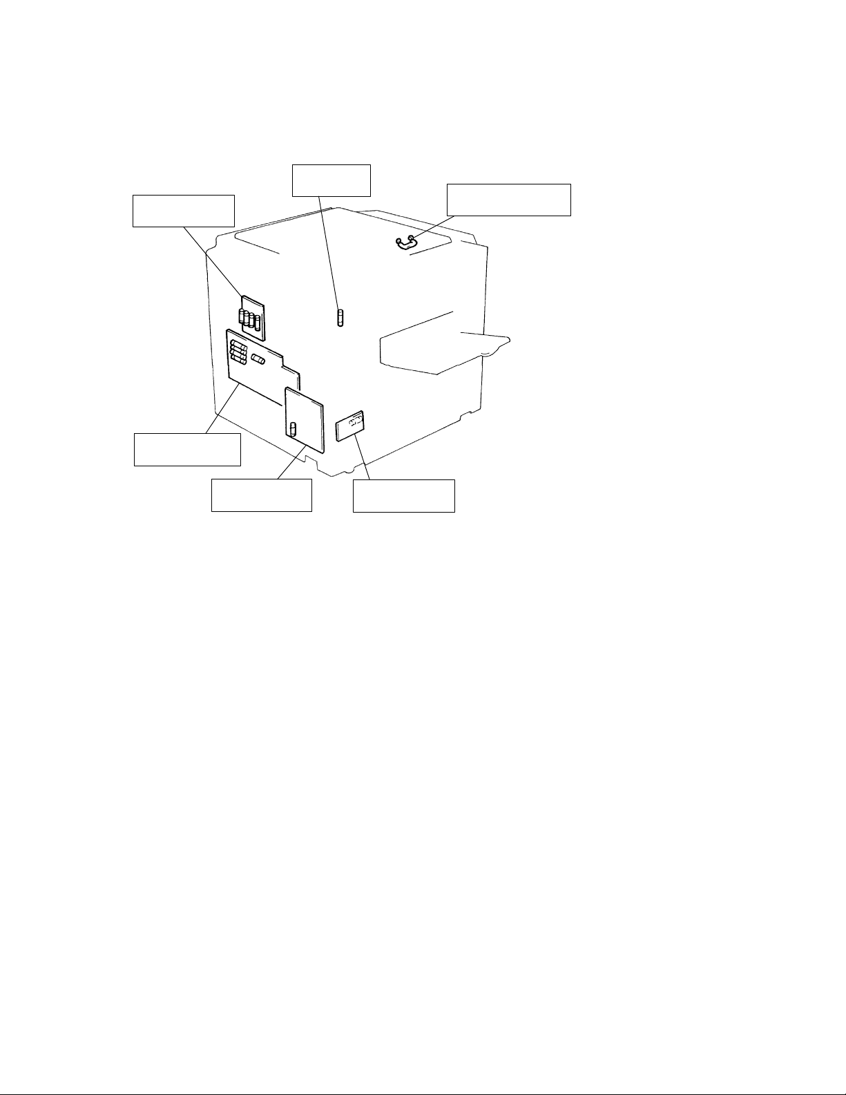
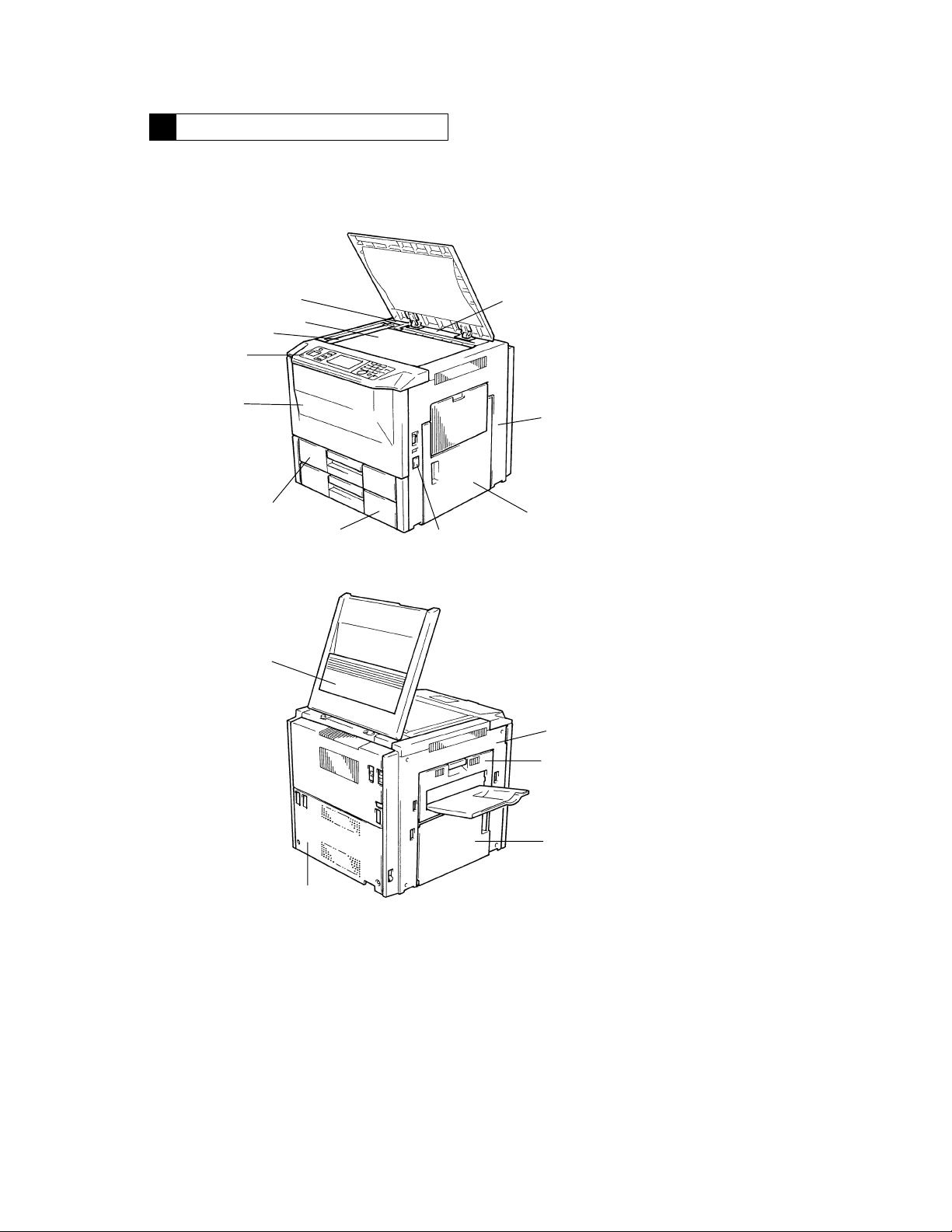
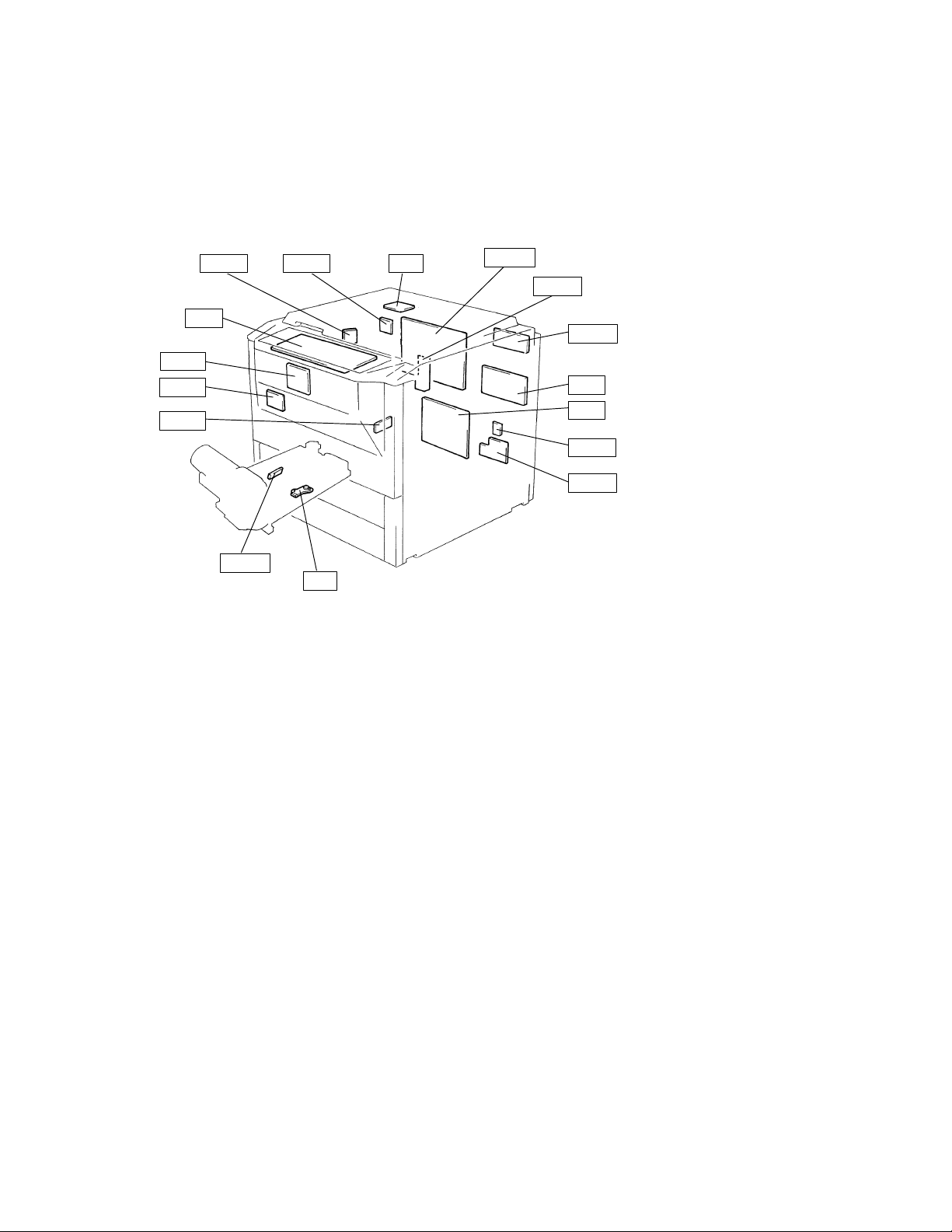
2-1. DOORS, COVERS, AND EXTERIOR PARTS: IDENTIFICATION AND
REMOVAL PROCEDURES
5
4
3
2
1
11
10
12
9
6
7
8
1156D002AA
13
14
15
16
1156D003AA
D-6

No. Part Name Removal Procedure
p
See
p.D-17
1 Front Door Swing down No. 1.!Remove two Front Door hinge shafts.
2 Control Panel Raise No. 12.!Swing down No. 1.!Open No. 8.!Re-
Original Width Scale Raise No. 12.!Remove two scale mounting screws.
3
Original Glass
4
5 Rear Upper Cover (Small) Raise No. 12.!Open No. 14.!Remove No. 13.!Re-
6 Rear Upper Cover Raise No. 12.!Open No. 14.!Remove No. 13.!Re-
7 Right Cover Open No. 8.!Open the Multi Bypass Table.!Remove
8 Right Door
(Manual Bypass Unit)
9 Counter Cover Snap off the Counter Cover. (It is secured by catches at two
10 2nd Drawer <Except 120V Areas>
11 1st Drawer
12 Original Cover Remove No. 12 by pulling up.
13 Upper Left Cover Swing down No. 14.!Remove six Upper Left Cover
14 Left Door (Exit/Duplex
Switching Unit)
15 Middle Left Cover Remove No. 13.!Remove two Middle Left Cover mounting
16 Rear Cover Remove six Rear Cover mounting screws.
Remove one belt mounting screw inside the Front Door.
move No. 7.!Swing down No. 14.!Remove No. 13.
Remove two control panel mounting screws.!Remove two
magnet attraction plate screws.!Unplug one connector
from MSC Board.!Remove one connector.
Note:When the Original Width Scale has been removed, use
care not to lose two springs.
move the screw cover.!Remove one Rear Upper Cover
(Small) mounting screw.
move No. 5.!Open No. 8!Remove No. 7.!Remove
one Rear Upper Cover mounting screw.
four Right Cover mounting screws.
Open No. 8.!Remove two cover mounting screws.
Remove the harness from one wiring saddle.!Unplug
three connectors.!Remove two Right Door mounting
screws.
places.)
See
. D-17
<120V Areas>
See p. D-18
mounting screws.
See p. D-61
screws.
!
!
D-7
1156SBD0202A
2-2. REMOVAL OF CIRCUIT BOARDS
When removing a circuit board, refer to “PRECAUTIONS FOR HANDLING THE PWBs” contained in
D
SWITCHES ON PWBs and follow the corresponding removal procedures given on the next page.
Replacement of a circuit board may call for readjustment or resetting of particular items.
D
The removal procedures given on the next page omit the removal of connectors and screws securing the
D
circuit board support or circuit board.
Where it is absolutely necessary to touch the ICs and other electrical components on the board, be sure
D
to ground your body.
PWB-H PWB-J UN2
UN1
PWB-B
PWB-I
PWB-D
PWB-G
UN3
PWB-A
PWB-R
PWB-F
HV1
PU1
PWB-L
PWB-C
1156D004AA
D-8

Symbol Part Name Removal Procedure
Slide
out
the
drawer
!
Remove
the
Holder
!
Remove
the
Slide
out
the
drawer
!
Remove
the
Cassette
Cover
!
Re-
PWB-A Master Board Remove No. 16.
PWB-B MSC Board Swing down No. 1.!Remove the Circuit Board cover.
PWB-C Power Supply Board Remove No. 16.!Remove the Toner Pipe.
PWB-D Noise Filter Board Remove No. 16.
PWB-E1 1st Drawer Paper Empty
PWB-E2 2nd Drawer Paper
PWB-F SCP Board Remove No. 16.
PWB-G AIDC Sensor Board Swing down No. 1.!Remove the IU.!Remove the PC
PWB-H AE Sensor Board Remove No. 3.!Remove No. 4.
PWB-I Tech. Rep. Settings
PWB-J Exposure Lamp
PWB-L Fuse Board Remove No. 16.
PWB-M1 1st Drawer Flexible
PWB-M2 2nd Drawer Flexible
PWB-R RAM Board Remove No. 16.
Readjustment/Resetting Involved in Replacement of PWB-G, PWB-R, UN2 and UN3
z
Board
Empty Board
Switches Board
Regulator
printed Circuit
printed Circuit
UN1 Control Panel Swing down No. 1!Remove No. 2.
UN2 Original Size Detecting
Board
UN3 ATDC Sensor Swing down No. 1.!Remove the IU.
UN5 1st Drawer Paper
Descent Key
UN6 2nd Drawer Paper
Descent Key
PU1 Power Supply Unit Remove No. 16.!Remove the Power Supply Unit Cover.
HV1 Hight Voltage Unit Remive No. 16.!Remove the HV1 Cover.
When PWB-G is replaced:
D
Adjust the exposure level in the Auto Exposure mode. (See p. D-72.)
When PWB-R (RAM Board) is replaced:
D
Carry out Memory Clear and then make the Tech. Rep. Choice, User’s Choice, and Adjust settings
again.
When UN2 is replaced:
D
Make the initial adjustment of the Original Size Detecting Board. (See p. D-68.)
When UN3 is replaced:
D
Discard the developer which had been used until UN3 was replaced, recharge the Developing Unit
with fresh starter, and adjust the ATDC. (See p. D-69.)
<EP4000 Except U.S.A., Canada and Europe>
Remove No. 16.!Remove the Toner Collecting Box.
Remove the Toner Pipe.
Slide out the drawer.!Remove the Holder.!Remove the
Paper Mounting Plate.
Drum Charge Corona.!Remove the PC Drum Paper Separator.
Swing down No. 1.!Remove the Circuit Board Cover.
Remove No. 16.!Remove PWB-A Mounting Bracket Assy.
Remove the ADF Connector Unit.!Remove the Expo-
!
sure Lamp Regulator Cover.
<EP4000 Except U.S.A., Canada and Europe>
Remove No. 16.!Remove the Toner Collecting Box.
Remove the Toner Pipe.
Slide out the drawer.
Remove No. 16.
Slide out the drawer.!Remove the Cassette Cover.!Remove the Switch Cover.
.
.
.
.
D-9
1156SBD0203
2-3. PAPER TAKE-UP/TRANSPORT SECTIONS
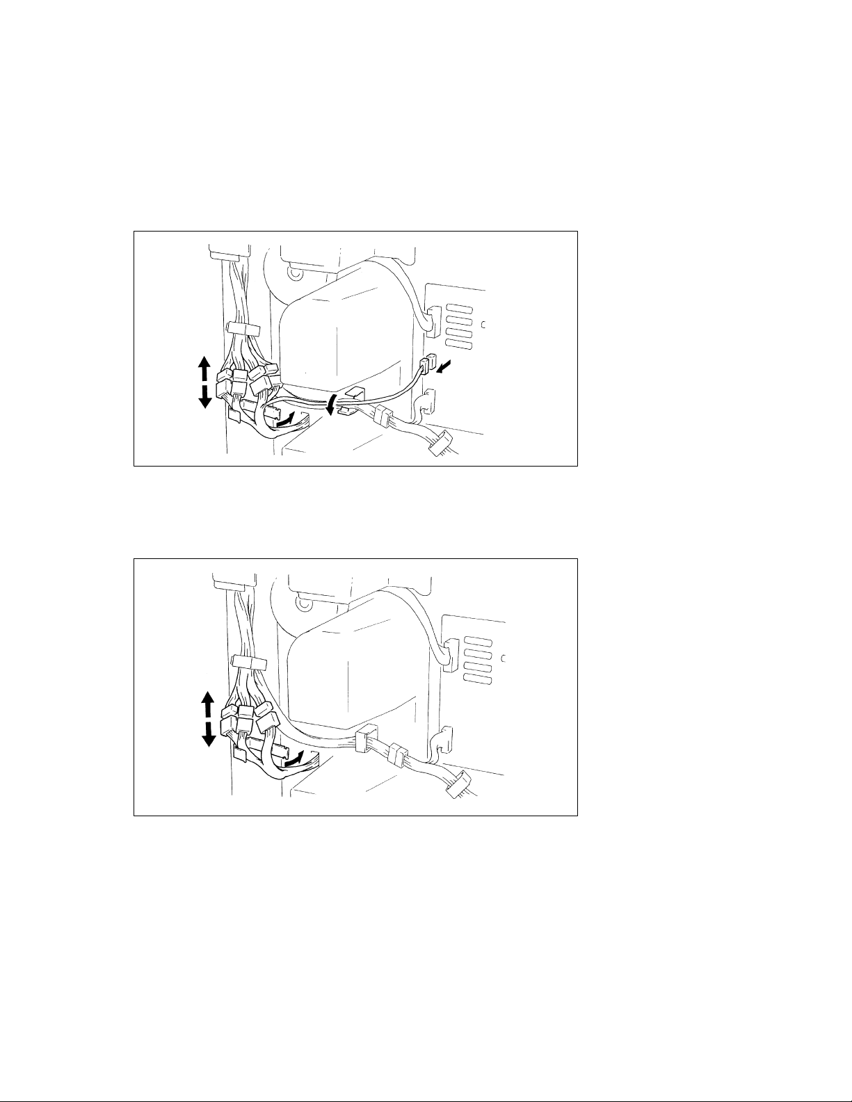
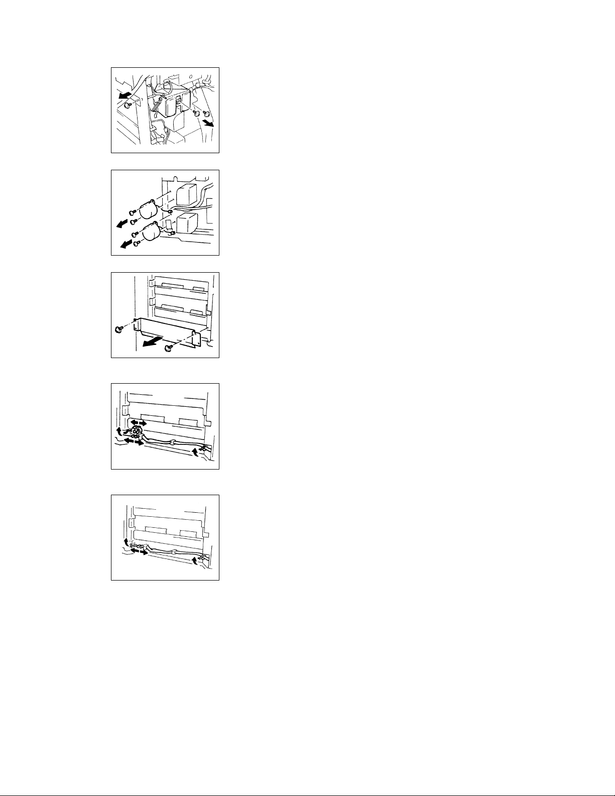
(1) Removal of the Paper Take-Up Unit
<Except 120V Areas>
1. Remove the Right Door, Right Cover, and Rear Cover.
2. Remove the 1st and 2nd Drawers. (For the removal of the 1st and 2nd Drawers, see p. D-17.)
3. Remove two locking wiring saddles.
4. Unplug one connector from Power Supply Board PWB-C.
5. Disconnect the hookup connector.
1156D005AA
<120V Areas>
1. Remove the Right Door, Right Cover, and Rear Cover.
2. Remove the 1st and 2nd Drawers. (For the removal of the 1st and 2nd Drawers, see p. D-18.)
3. Remove one locking wiring saddle.
4. Disconnect the hookup connector.
D-10
1156D006CA
1156D007AA
1134D006AA
1134D007AA
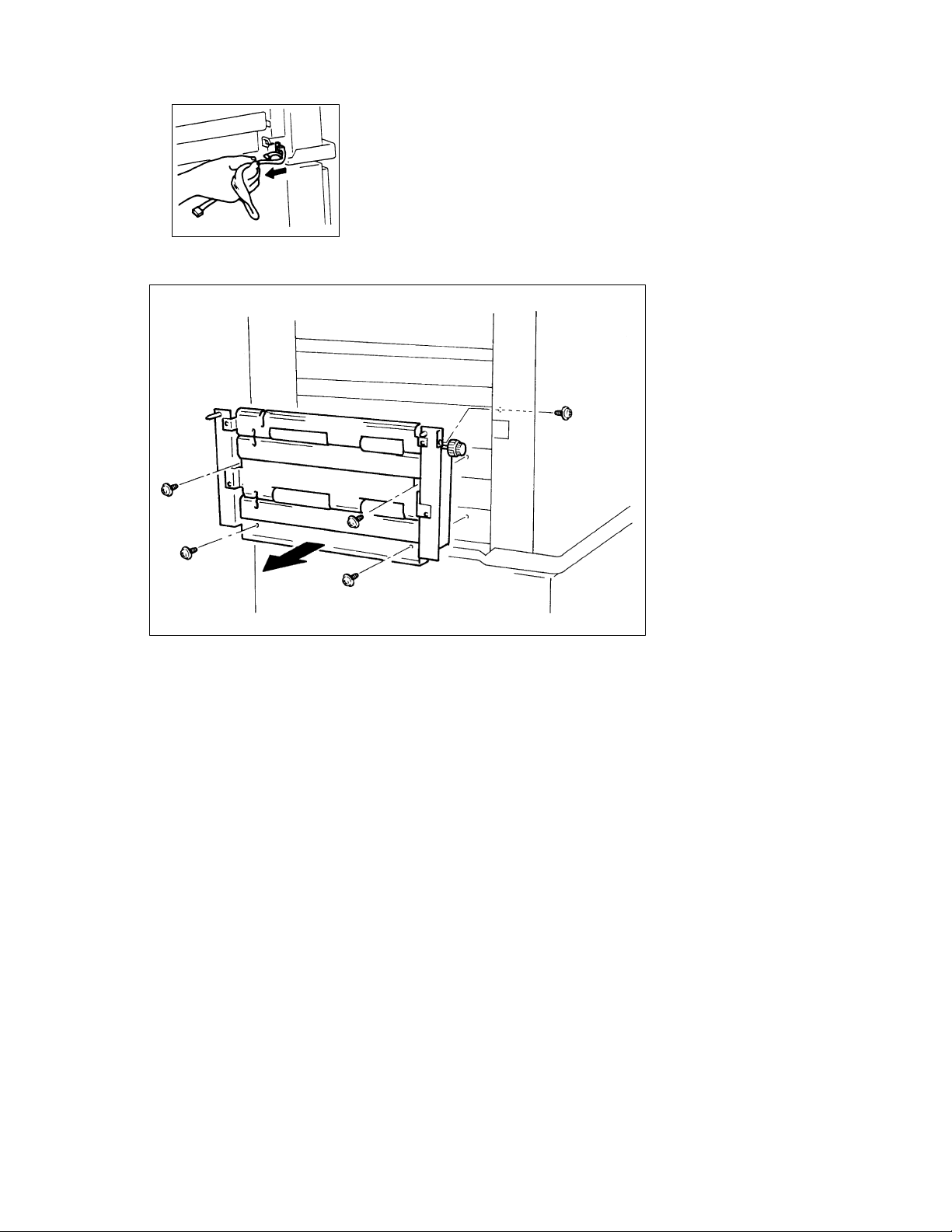
6. Remove three screws to free the Paper Take-Up Connector Assy.
7. Remove two screws each to free 1st Drawer Paper TakeUp Motor M11 and 2nd Drawer paper Take-Up Motor M12.
* For ease of understanding, the illustration shows where
the connectors and Paper Take-Up Motors are removed.
8. Remove two screws and the Paper Guide Plate.
<Except 120V Areas>
<120V Areas>
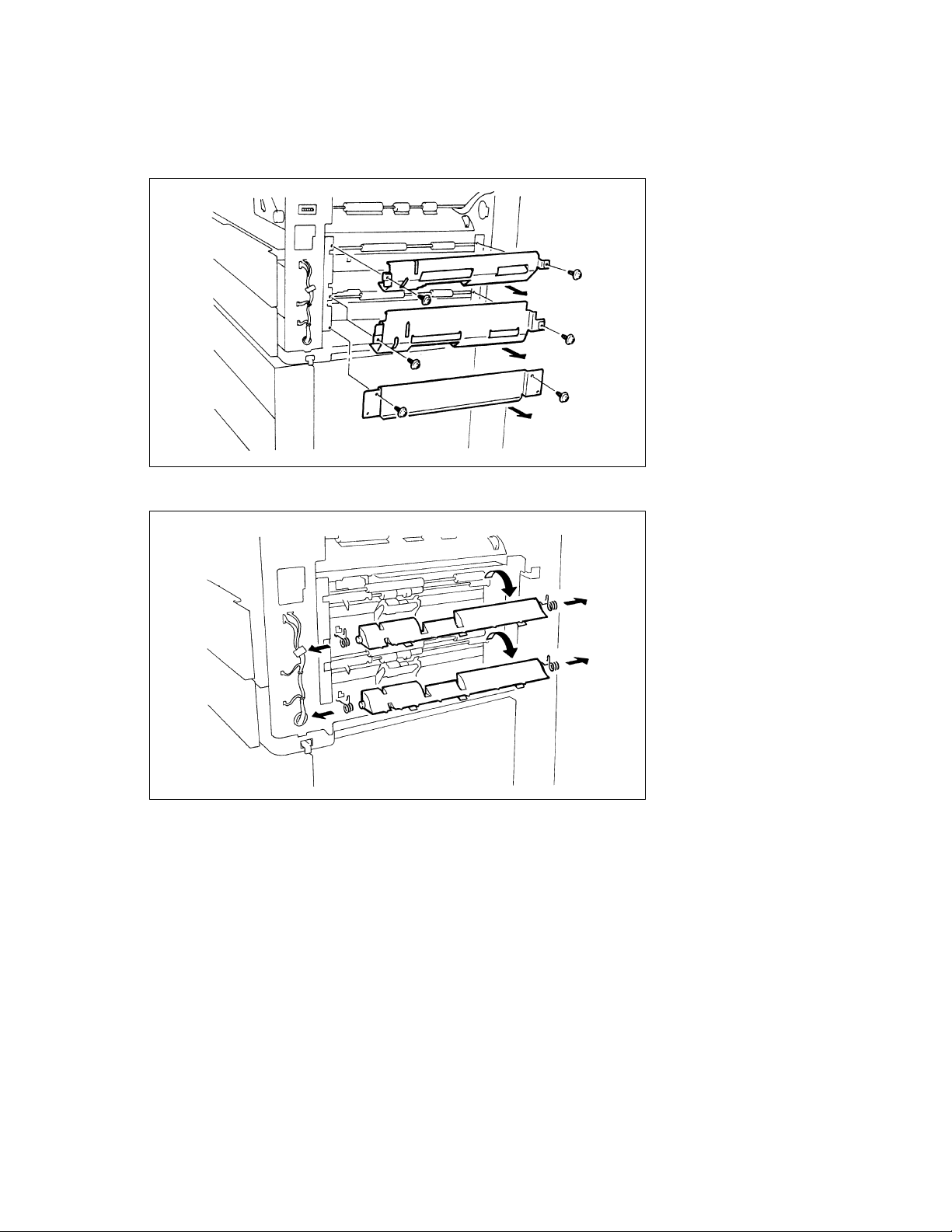
9. Remove two edge covers with locks.
10. Unplug three hookup connectors.
1134D008AA
9. Remove two edge covers with locks.
10. Unplug one hookup connector.
1156D008CA
D-11
11. Pull the harness out to the front from the rear frame.
1134D009AA
12. Remove five screws and the Paper Take-Up Unit.
D-12
1156D009AA
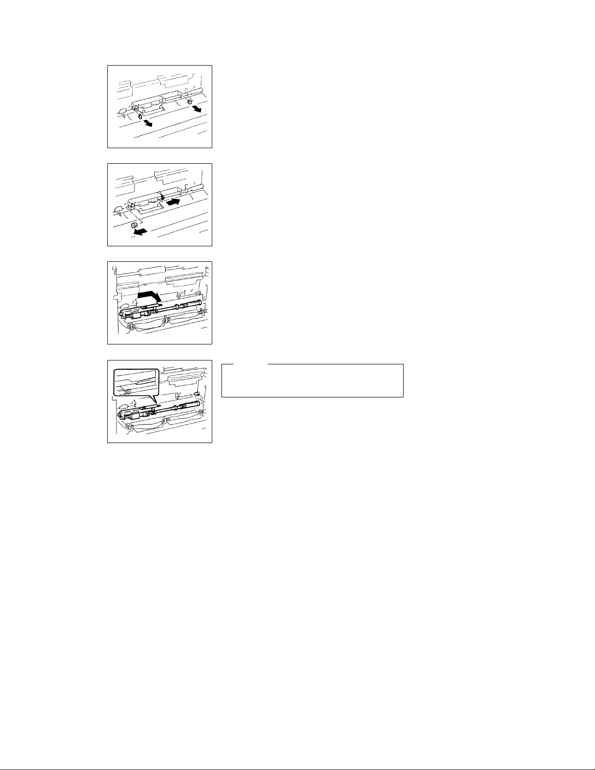
(2) Removal of the Paper Take-Up Roll/Feed Roll Assy and Separator Roll
Assy
1. Remove the Right Door.
2. Remove two screws and the Paper Guide Plate from each drawer.
1134D011AA
3. Unhook the front and rear springs from the copier frame. Remove the Paper Separator Roll/Paper
Guide Plate Assy by turning it about 90_in the direction of the arrow.
D-13
1156D010AA
4. Remove one screw and the Paper Separator Roll Assy
Mounting Bracket from each drawer. (The illustration
shows how the Paper Separator Roll Assy is removed
from the 2nd Drawer.)
1156D011AA
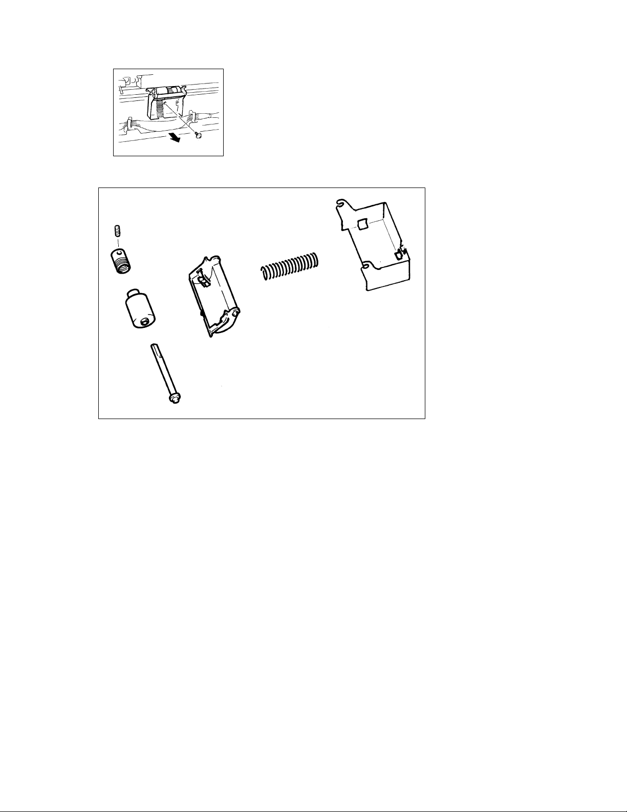
5. Disassemble the Paper Separator Roll Assy.
D-14
1156D012AA
1156D013AA
1156D014AA
1156D015AA
6. Remove two C-clips from each Paper Take-Up Roll/Feed
Roll Assy. (The illustration is for the Paper Take-Up Roll/
Feed Roll Assy for the 2nd Drawer.)
7. Remove the bushing from the front end of each Paper
Take-Up Roll/Feed Roll Assy.
8. Remove the rear bushing from the holder.
9. Move the coupling holder of each Paper Take-Up Roll/
Feed Roll Assy in the direction of the arrow to work it off the
pin of the copier. This allows the Paper Take-UpRoll /Feed
Roll Assy to come out of the copier.
1156D016AA
NOTE
When reinstalling the Paper Take-Up Roll/Feed Roll Assy,
place it above the Pressure Release Lever.
D-15
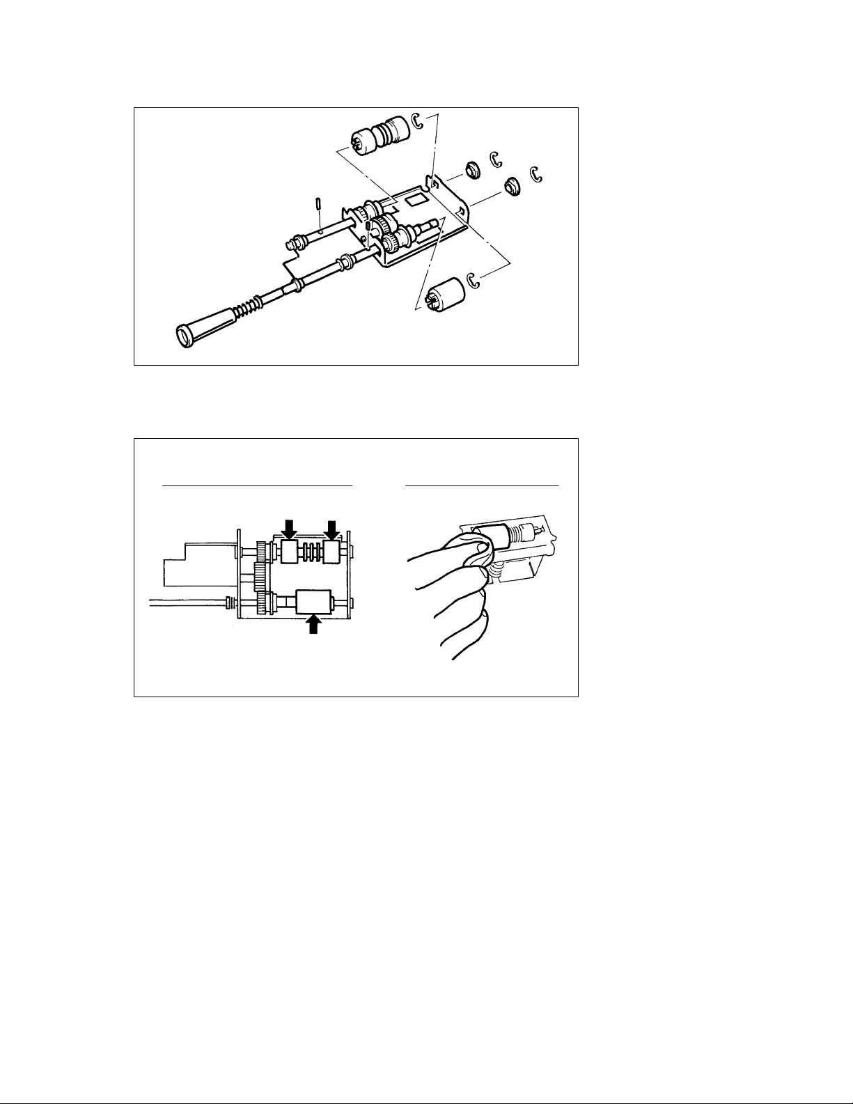
10. Disassemble the Paper Take-Up Roll/Feed Roll Assy.
*Keep the lock pin for later use.
1156D017AA
(3) Cleaning of the Paper Take-Up Roll, Feed Roll, and Separator Roll
1. Remove each Paper Take-Up Roll/Feed Roll Assy.
2. Remove each Paper Separator Roll Assy.
3. Using a soft cloth dampened with alcohol, wipe each roll clean of dirt.
Cleaning the Paper Take-up Roll/Feed Roll Cleaning the Paper Separator Roll
1156D018AA
1156D019AA
D-16
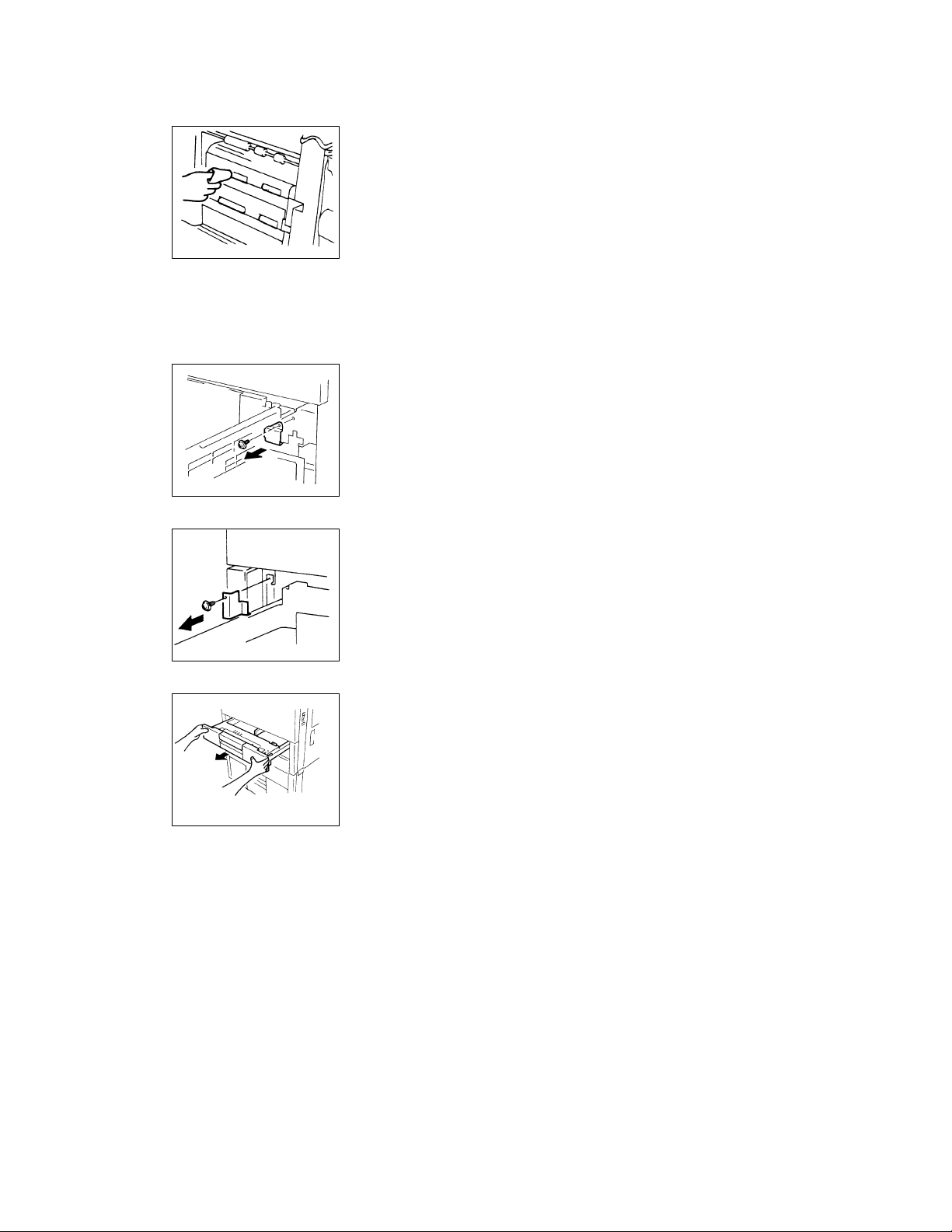
(4) Cleaning of the Vertical Transport Rollers
1. Remove the Right Door, Right Cover, and Rear Cover.
2. Using a soft cloth dampened with alcohol, wipe each roller
clean of dirt.
1134D016AA
(5) Removal of the Drawers
*Though the following steps and illustrations are for the 1st Drawer, the same procedure applies also to
the 2nd Drawer.
<Except 120V Areas>
1. Slide out the drawer and remove one screw and the right
stopper.
1156D020AA
2. Remove one screw and the left stopper.
1134D133AA
1134D143AA
3. Remove the drawer from the copier.
D-17
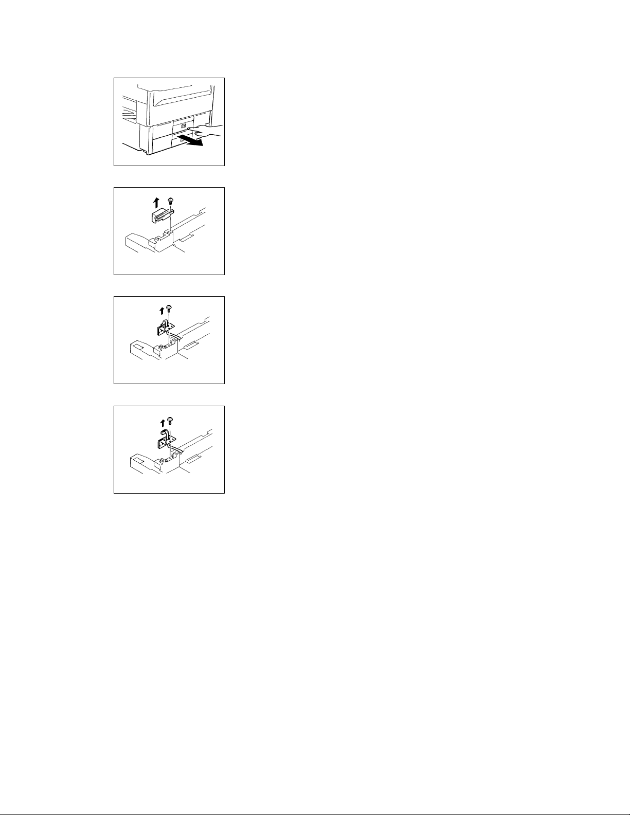
<120V Areas>
1. Turn ON Power Switch S1.
2. Press the Paper Descent Key and then slide out the drawer.
1156D023AA
3. As with the metric areas, remove the right and left stoppers.
4. Remove one screw and the hookup connector cover.
1134D139CA
5. Remove one screw and the hookup connector mounting
bracket.
1134D140CA
1134D141CA
6. Unplug the hookup connector. Remove the drawer.
D-18
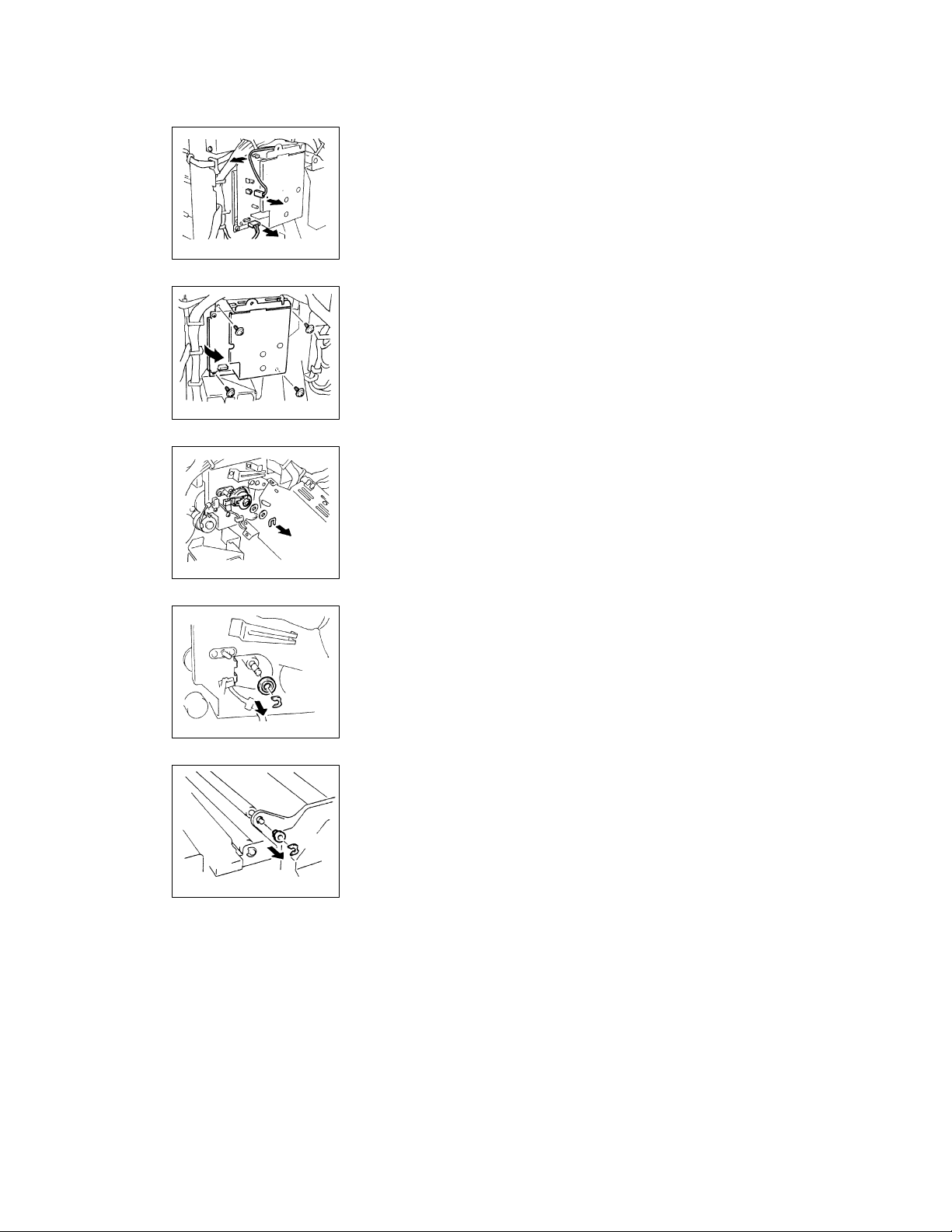
(6) Removal of the Upper Synchronizing Roller
1. Swing down the Front Door.
2. Swing the Transport Section Release Lever down.
3. Remove the Rear Cover.
4. Unplug the bias terminal from High Voltage Unit HV1.
5. Unplug CN1 of HV1.
1156D024AA
6. Remove two screws to free HV1.
1156D025AA
7. Snap off one E-ring to free Synchronizing Roller Clutch
CL2.
1156D026AA
Rear
1156D027AA
Front
1134D025AA
8. Snap off the E-ring and remove the bushing from the rear
end of the Upper Synchronizing Roller.
9. Swing down the Front Door and slide out the IU.
10. Snap off the E-ring and remove the bushing from the front
end of the Upper Synchronizing Roller.
D-19
11. Remove the Upper Synchronizing Roller.
1156D028AA
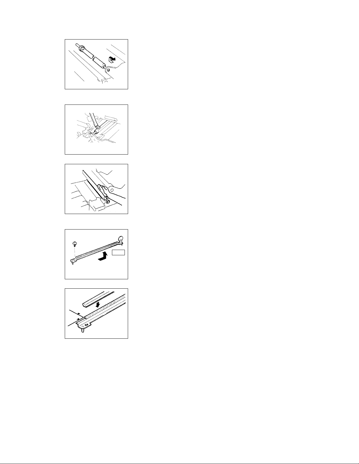
(7) Cleaning of the Upper and Lower Synchronizing Rollers
1. Swing down the Front Door and slide out the IU.
2. Using a brush or a soft cloth dampened with alcohol, clean
the Upper Synchronizing Roller.
1136D092AA
3. Swing down the Transport Section Release Lever.
4. Using a brush or a soft cloth dampened with alcohol, clean
the Lower Synchronizing Roller.
1134D027AA
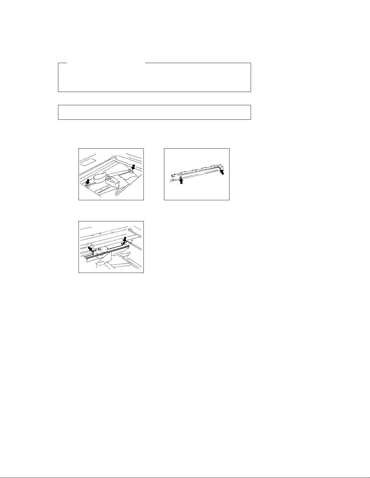
(8) Replacement of the Paper Dust Remover
1. Swing down the Front Door and slide out the IU.
2. Loosen the screw that secures the Paper Dust Remover
Assy at the rear of the copier.
Rear
1136D093AA
1136D094AA
3. Remove the screw that secures the Paper Dust Remover
Assy at the front of the copier.
4. Remove and replace the Paper Dust Remover Assy.
5. When only the Paper Dust Remover is to be replaced, affix
the new one along the reference line as shown on the left.
D-20

(9) Cleaning of the Paper Dust Remover
1. Remove the Paper Dust Remover Assy.
2. Using a brush, whisk dust off the Paper Dust Remover.
1136D095AA
D-21
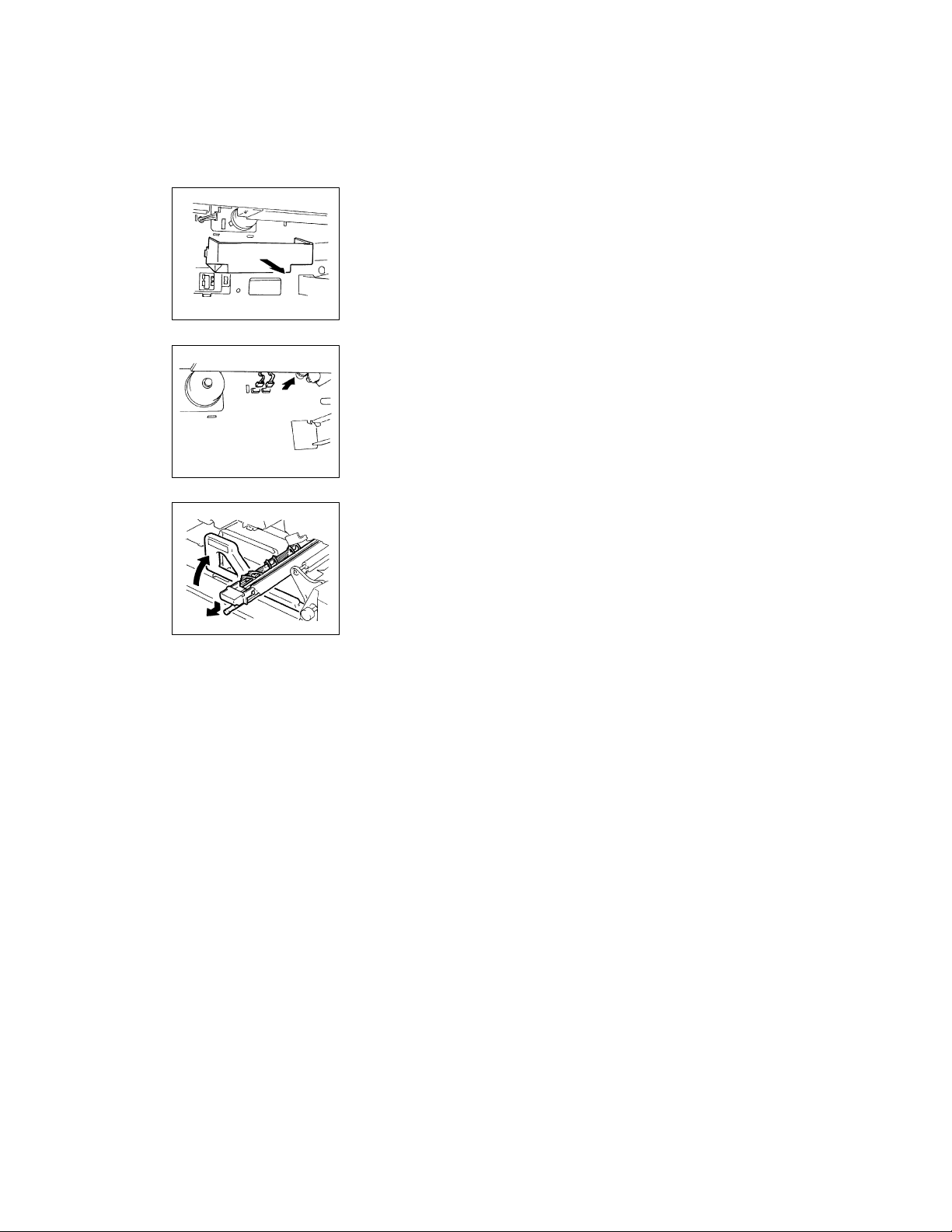
(10) Removal of the Suction Unit
1. Remove the 1st and 2nd Drawers.
2. Swing down the Front Door and slide out the IU.
3. Remove the Paper Dust Remover Assy.
4. Remove the Fusing Unit.
5. Remove the motor cover.
1156D029AA
6. Unplug two connectors from the lower end of the Suction
Unit.
1156D030AA
7. Swing the Transport Section Release Lever back to its
original position.
8. Pressing down the Image Transfer/Paper Separator Coronas Unit, pull it out of the copier.
1156D031AA
D-22
1156D032AA
1136D101AA
1134D028AA
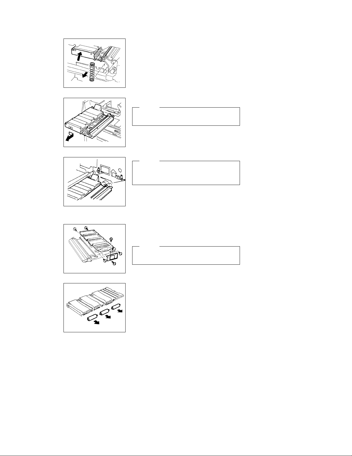
9. Swing down the Transport Section Release Lever.
10. Holding up the Suction Unit, remove the compression coil.
11. Remove the Suction Unit by sliding it to the right.
NOTE
When removing and reinstalling the Suction Unit, use care
not to bend the ground plate located on the right in the rear.
NOTE
When reinstalling the Suction Unit, make sure that two
positioning pins on the copier fit into the positioning holes
in the Suction Unit.
(11) Disassembly of the Suction Unit
1. Remove the Suction Unit.
2. Remove two screws and the duct.
3. Remove four screws and the Suction Drive Unit.
When reinstalling the Suction Drive Unit, try to press it
down against the Suction Base Plate.
1136D102AA
4. Remove three driven rolls.
1136D103AA
D-23
NOTE
 Loading...