

Konica Minolta bizhub C754E, bizhub C654E Installation Manual
E-1
INSTALLATION MANUAL
/
A2X0-9971-00
<Important>
Be sure to correctly follow the procedures in order as explained in this Installation Manual.
If you do not follow the procedure in order, the image trouble may occur.
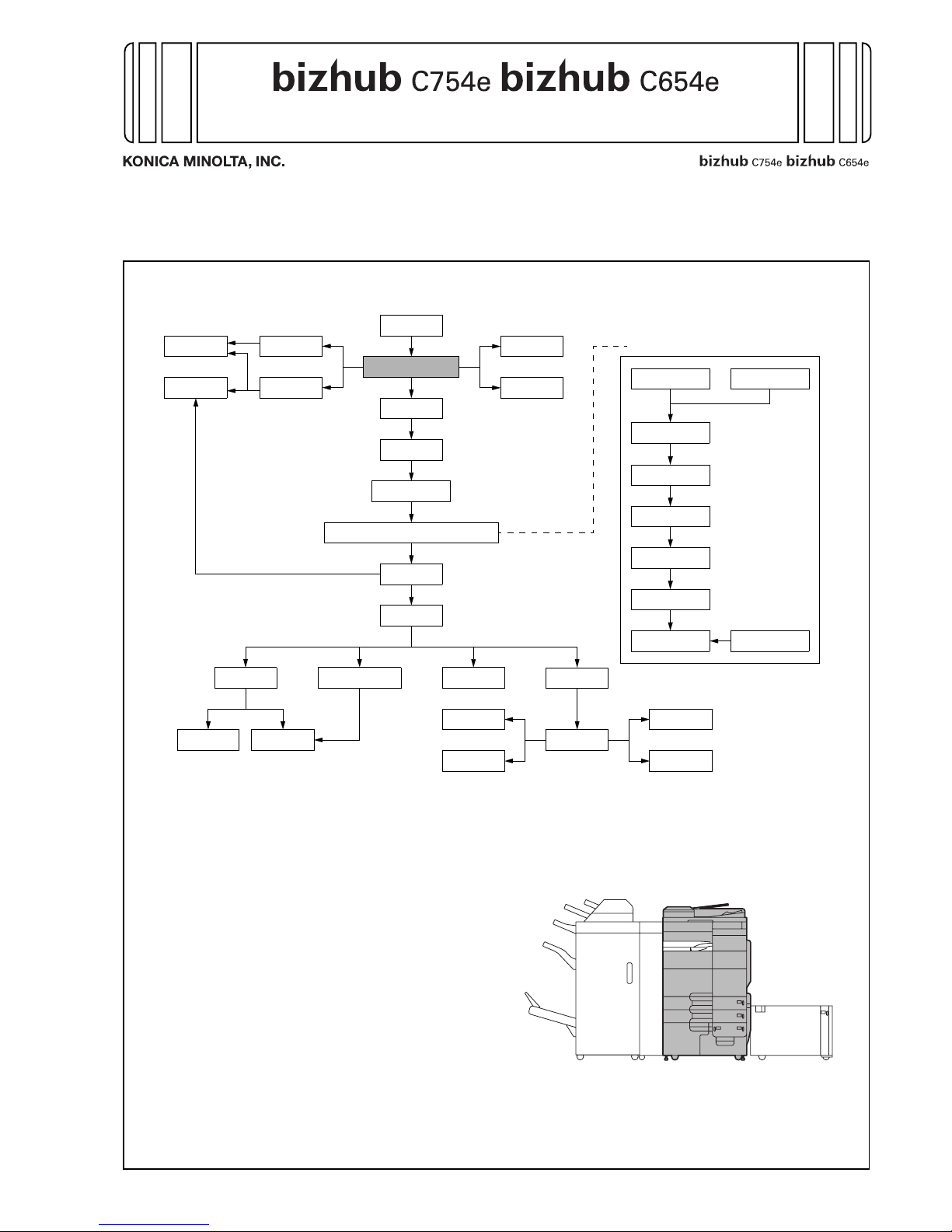
I. Outline of installation procedures
When installing the machine and associated options as a system, follow the order shown on the upper.
Note:
• For the detailed installation procedures for each
option, follow the instructions given in the corresponding installation manual and perform the
procedures correctly.
• Once the Power Switch is turned ON, do not
turn OFF it until the installation work has been
completed.
• When transporting the machine, assign an adequate number of persons to the job and follow
the specified correct procedures.
(mass: approx. 221 kg (487-3/16 lb))
UK-204
*1
Machine
Electronic system options
SP-501
EK-604
*1
EK-605
*1
SC-508
*1
VI-506
*1
IC-414
*1
FK-511
MK-735
LU-204
LU-301
MK-715
OT-503
HT-508
*2
KH-102
✱ Electronic system options
WT-506
WT-509
AU-201
AU-102
ZU-606
PI-505
JS-602
FS-535
PK-521
SD-512
FS-534
PK-520SD-511
FS-534SD
*1
: No particular order in installation procedures
*2
: Varies depending on the applicable marketing area
FK-508
*2
MK-728
*2
KP-101
A2X0IXC001DA
Applied Machines: /
E-2
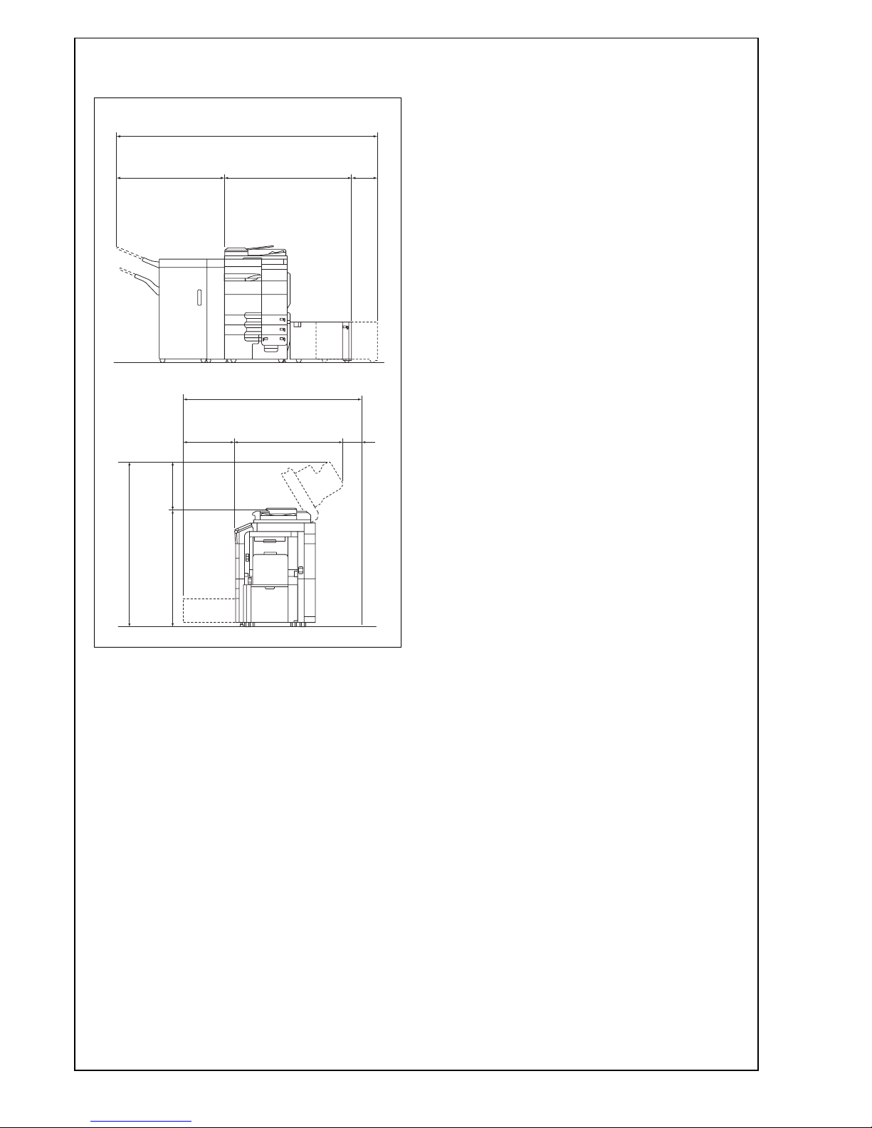
II. Installation space (unit: mm (inch))
bizhub C754e + ZU-606 + FS-535 + LU-204
III. Pre-installation check items
1. Select a level and stable place for installing the
machine.
2. Be sure to use a power source of the voltage and
frequency indicated in the product specifications.
Ensure that the current carrying capacity of the
power outlet is at least equal to the current listed
in the product specifications.
3. Power the machine directly from a dedicated
power outlet. (Do not use an extension cord.)
4. Do not plug or unplug the power cord with wet or
dirty hands, otherwise you may get an electric
shock.
5. Avoid a hot and humid environment, or a place
exposed to direct sunlight.
6. Avoid a dusty location, or a place near volatile
and flammable substances.
7. Avoid a poorly ventilated place.
IV. Notes on using touch panel
Be sure to instruct users on the following points.
• This machine uses a capacitive touch panel.
When you touch the touch panel, use your finger or the stylus pen supplied with the machine.
If you touch the panel using your nail or a pen
tip instead of using your finger or the stylus pen,
the touch panel does not respond normally.
• Pressing the touch panel hard may cause dam-
age.
• Do not strongly press the panel or press it using
the sharp tip of mechanical pencils.
• The key is a finger tapping (quick light touch
using a finger) operation.
A2X0IXC002DA
498
(19-5/8)
1027
(40-7/16)
1155
(45-1/2)
495
(19-1/2)
1252
(49-5/16)
1575 (62-1/16)
1650 (64-15/16)
238
(9-3/8)
50
(2)
1066
(41-15/16)
2556 (100-5/8)
E-3
V. Accessory parts
* Varies depending on the applicable marketing
area
Note:
The parts shown below are used when installing
options. Keep them safe.
• Tray label/paper size label: Large capacity unit
(LU-301)
• Label (Super G3 label): Fax kit
Note:
This manual provides the illustrations of the accessory parts and machine that may be slightly different in shape from yours. In that case, instead of
the illustrations, use the appearance of your
machine to follow the installation procedure. This
does not cause any significant change or problem
with the procedure.
VI. Unpacking the machine
Whether the slope is supplied with this machine or
not depends on your marketing areas. Follow the
notes below.
Note:
• When the slope is supplied with the machine,
follow the procedure, <A. When using the supplied slope>.
• When the slope is not supplied with the
machine, follow the procedure, <B. When using
the jig slope>.
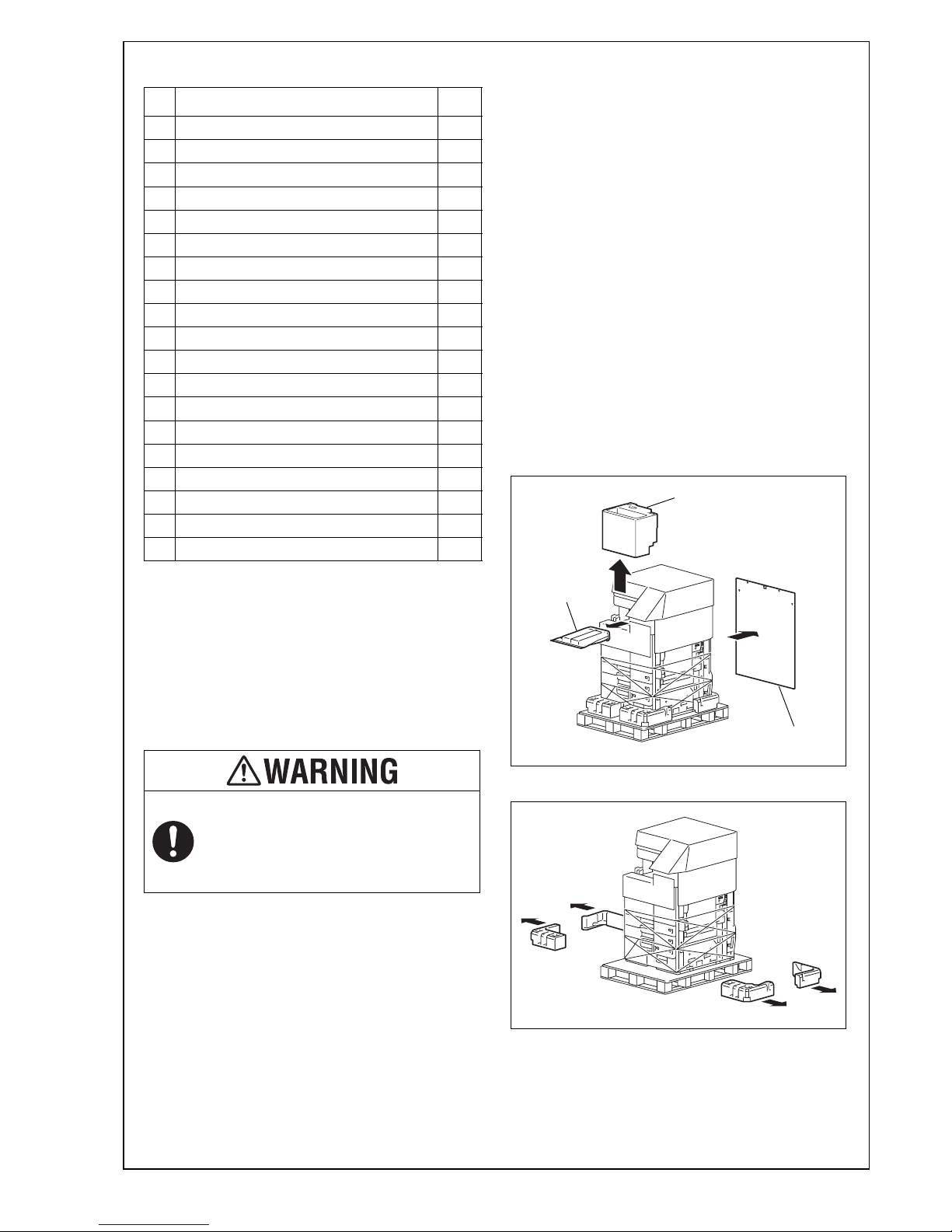
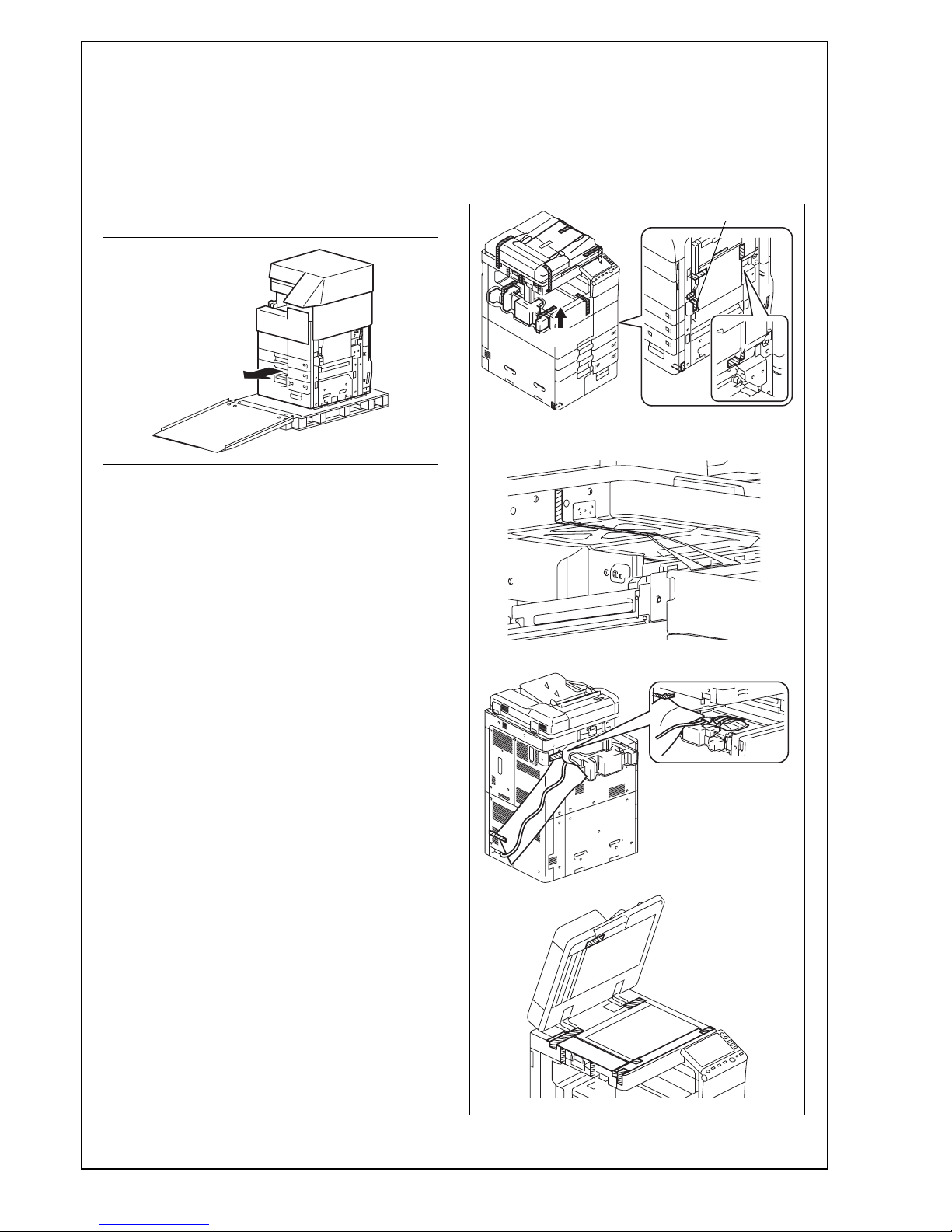
<A. When using the supplied slope>
1. Open the shipping box and remove the packag-
ing materials.
Note:
• Keep the supplied slope and cushion A that are
removed in this step for later use.
• The cushion B contains accessory parts.
Depending on the applicable marketing area,
the cushion B may also contain the power cord.
2. Remove the fixing materials (upper).
No. Name Q’ty
1. User’s guide holder 1
2. Quick start guide 1
3. Installation manual 1 set
4. User’s guide CD 1
5. CD-ROM 1 set
6. Tray label/Paper size label 1 set
7. Label (Legal restrictions on copying) * 1
8. Label (Super G3 label) 1
9. Panel sheet 1
10. Chart 1
11. Cap A (black) 2
12. Cap B (white) 2
13. Power cord * 1
14. Connector cover 1
15. Scanner cover 1
16. Mounting screw 1
17. Spacer 1
18. Power cord instruction * 1
19. Stylus pen 1
After unpacking, be sure to get rid of the
packaging materials and keep them out of
the reach of children.
Putting the head in the plastic bag
involves danger of suffocation.
A2X0IXE05 3DA
Supplied slope
Cushion B
Cushion A
A2X0IXC004DA

E-4
3. Hold onto the handle of the machine and tilt the
machine to the right and left. Under this condition,
remove the fixing materials (lower).
4. Separate the cushion into two and install them to
the pallet (at two places).
5. Take out the slope and protective tape and
remove nails from the plastic bag.
6. Position the slope as illustrated and drive nails in
to fix the slope in position.
Caution:
Insert the nails in the outer holes.
7. Holding onto the front cover and the back panel
of the machine, slide the machine down along the
slope.
Caution:
Machine mass: 221 kg (487-3/16 lb)
• Perform this step on a level, stable site and
assign an adequate number of persons.
• When sliding the machine down, do not hold
onto the scanner portion.
• Do not insert your leg under the slope.
A2X0IXC005DB
A2X0IXE06 9DA
A2X0IXE05 4DA
A0P0IXC067DA
A2X0IXE05 5DA
Nail
Nail
A2X0IXE05 6DA
E-5
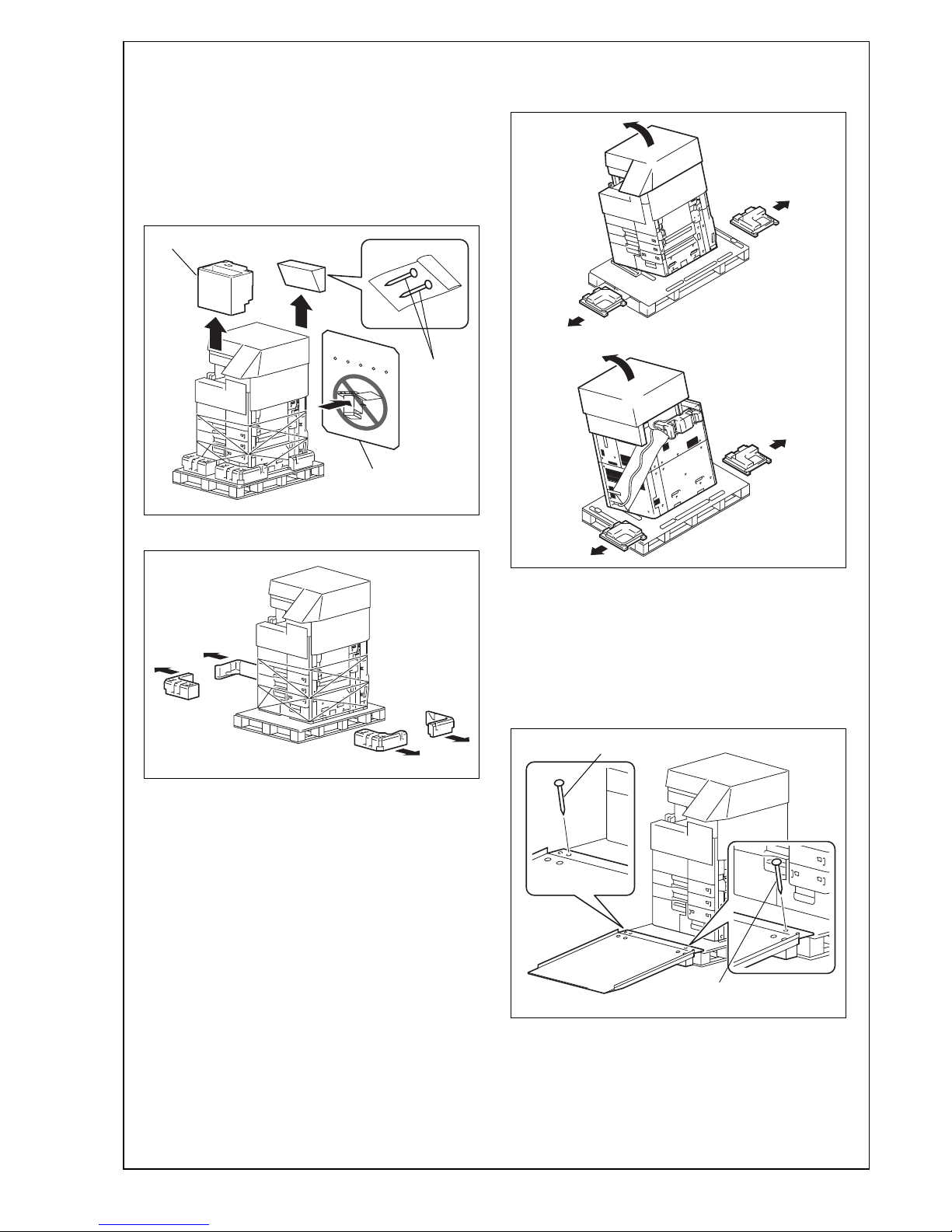
<B. When using the jig slope>
1. Open the shipping box and remove the packaging materials.
Note:
• Do not use the corrugated cardboard as slope.
• The nails removed in this step are used in step
4 to hold the slope in place.
• The cushion shown in the illustration contains
the power cord and accessory parts.
2. Remove the fixing materials (upper).
3. Hold onto the handle of the machine and tilt the
machine to the right and left. Under this condition,
remove the fixing materials (lower).
4. Place the jig slope as shown and insert the nails
into the holes to fix the slope in position.
Caution:
• As the slope is not supplied with the machine,
prepare a jig slope.
• Make sure that the nails are inserted com-
pletely into the holes and the slope is held in
place.
A2X0IXC003DA
Nail
Cushion
Corrugated
cardboard
A2X0IXC004DA
A2X0IXC005DB
A2X0IXC051DB
A2X0IXC006DA
Nail
Nail
E-6
5. Holding onto the front cover and the back panel
of the machine, slide the machine down along the
slope.
Caution:
Machine mass: 221 kg (487-3/16 lb)
• Perform this step on a level, stable site and
assign an adequate number of persons.
• When sliding the machine down, do not hold
onto the scanner portion.
• Do not insert your leg under the slope.
VII. Removing protective tape, packing
and other shipping materials
1. Remove the protective tape and protective materials.
Note:
After removing protective tape B, be sure to lock
the lever.
A2X0IXC007DA
A2X0IXC008DB
A
A2X0IXC009DB
A2X0IXC011DB
<Viewed from point A>
A2X0IXC010DB
B
E-7
2. Open the right door and remove the protective
tape and the protective material.
3. Close the right door.
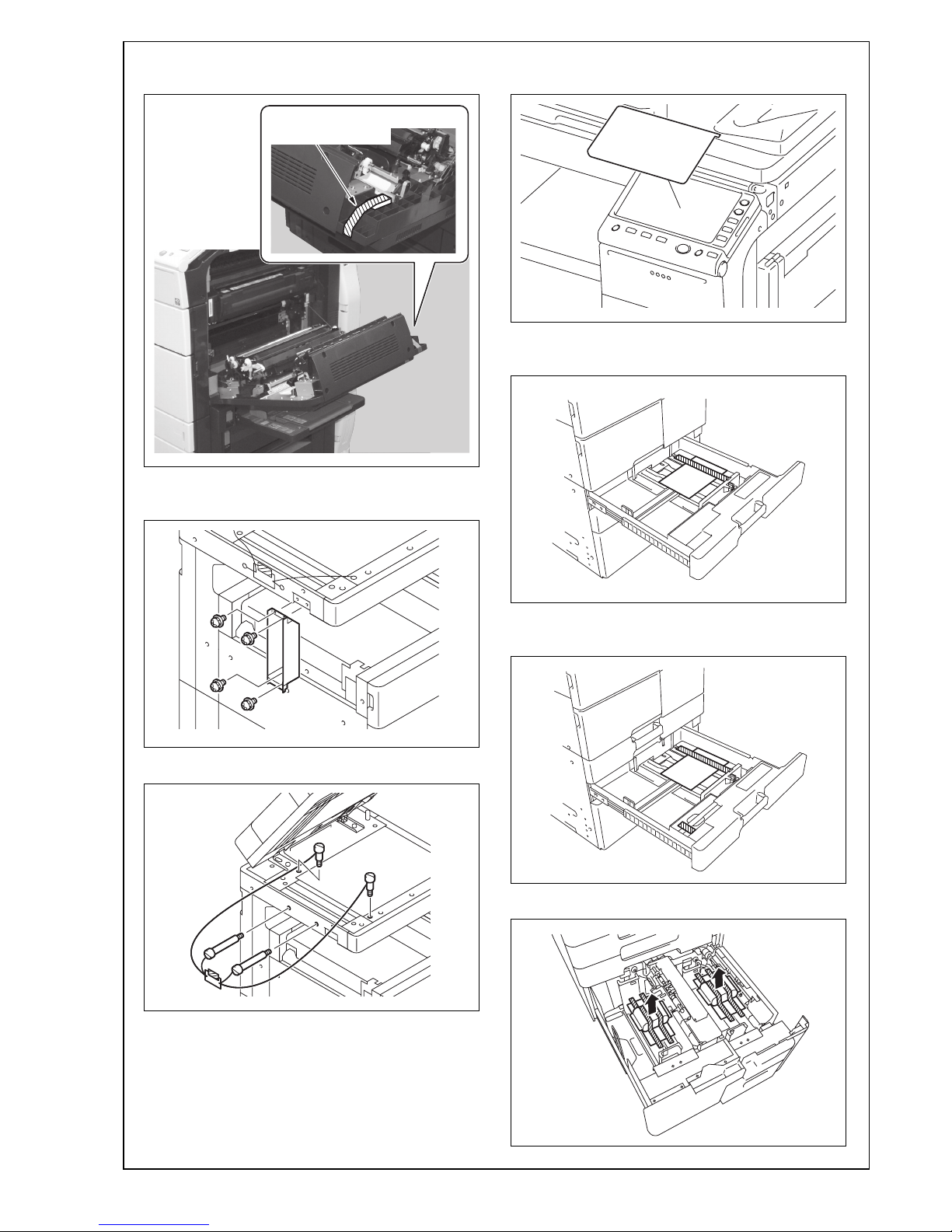
4. Remove the reinforcement plate. (Four screws)
5. Remove the locking screws.
6. Remove the protective sheet from the control
panel.
7. Pull the tray 1 out and remove the protective tape
from the tray.
8. Pull the tray 2 out and remove the protective tape
from the tray.
9. Pull trays 3 and 4 out and remove the desiccants.
A2X0IXC074DA
Protective tape/
Protective material
A2X0IXC012DB
A2X0IXC013DA
A2X0IXC014DA
A2X0IXC015DC
A2X0IXC016DC
A2X0IXC058DB
E-8
10. Remove the protective tape from trays 3 and 4.
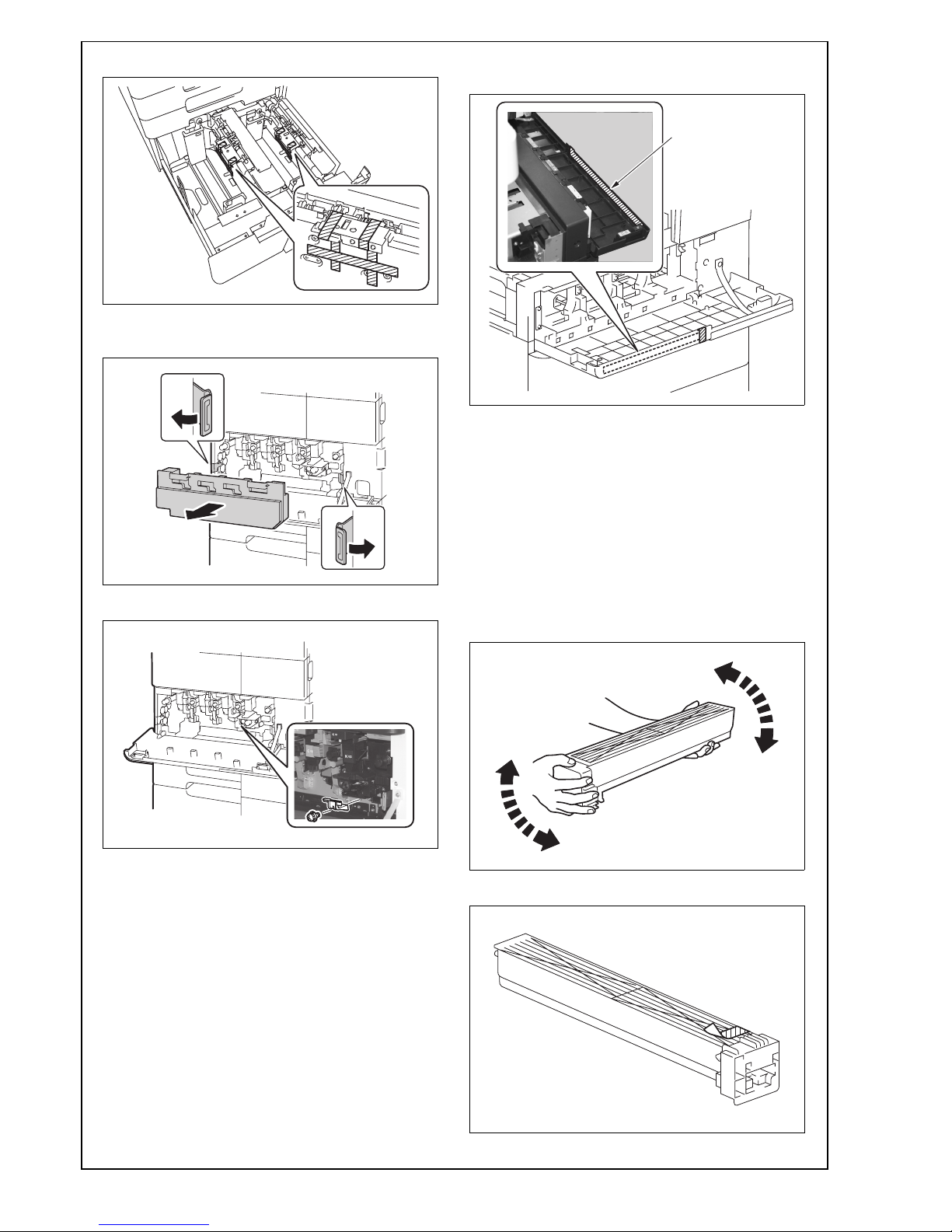
11. Open the lower front door and remove the waste
toner box.
12. Remove the packing bracket. (One screw)
13. Install the waste toner box and close the lower
front door.
14. Open the upper front door and remove the protective tape.
VIII. Installing the toner cartridges
Note:
Since no toner cartridges are supplied with the
machine, purchase a toner cartridge (of different
colors) separately.
1. Shake the toner cartridge up and down five to ten
times.
Note:
Shake the cartridge adequately. Otherwise, it may
cause trouble.
2. Remove protective tape of the toner cartridge.
A2X0IXC076DA
A2X0IXC017DA
A2X0IXC018DB
A2X0IXC075DA
Protective tape
A00JIXC018DA
A00JIXC224DA
E-9
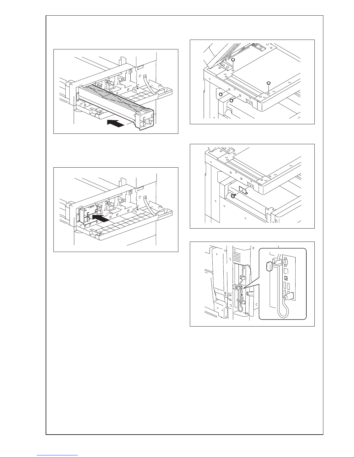
3. Insert the toner cartridge into the machine.
Note:
Make sure that the color is same between inserting port and the toner cartridge.
4. Push the toner cartridge all the way in.
Note:
Make sure that the toner cartridge is pushed all the
way in.
5. Using the same procedure, install the toner cartridges for other colors of toner.
6. Close the upper front door.
IX. Mounting the accessory parts
1. Attach the supplied caps A and B.
2. Install the supplied scanner cover. (One supplied
mounting screw)
3. Attach the supplied connector cover.
A2X0IXC060DA
A2X0IXC061DA
A2X0IXC019DA
A2X0IXC020DA
A2X0IXC021DA
 Loading...