

Page 1

Kodak DryView
8900 LASER IMAGER
Modifications
Page 2
{Modification/Type1}{Production}{Health Group}{Internal}
Publication No. 8F2148
MODIFICATION INSTRUCTIONS
for the
Kodak DryView 8900 LASER IMAGER
Service Codes: 1442 and 4878
Modification No. 10
Type 3 Optional
12JUL05
Purpose: To install the Anti-Virus solution on Kodak products.
Important
Qualified service personnel must install this modification.
Service Effects: None
Special Requirements: The customer must provide the following software:
• McAfee ePolicy Orchestrator (ePO) AGENT Version 3.5 on a CD-ROM
• McAfee VirusScan SOFTWARE Version 7.1
Serial Numbers: All
Installation Time: 1.5 hours
Special Tools: • A LAPTOP with the following software installed:
– Symantec pcAnywhere SOFTWARE
– Kodak SECURE LINK CLIENT SOFTWARE Version 1.2.2 or higher
Parts Status: None
Parts Requirements: None
HEALTH GROUP
Restricted Information
© Eastman Kodak Company, 2005
Page 3

PLEASE NOTE The information contained herein is based on the experience and knowledge relating to the
subject matter gained by Eastman Kodak Company prior to publication.
No patent license is granted by this information.
Eastman Kodak Company reserves the right to change this information without notice, and
makes no warranty, express or implied, with respect to this information. Kodak sh all not be liable
for any loss or damage, including consequential or special damages, resulting from any use of
this information, even if loss or damage is caused by Kodak’s negligence or other fault.
This equipment includes parts and assemblies sensitive to damage from electrostatic
discharge. Use caution to prevent damage during all service procedures.
MODIFICATION KIT
The parts are not in Service Parts Management. Order the publications from your Regional Dispatch Center or
Regional Specialist. See Step 2
.
2 12JUL05 – 8F2148
Page 4
Before Installing the Modification
[1] Check that the customer wants Kodak to install the Anti-Virus Solution.
[2] Until the publications are included in the next release of the Service Collection CD, ask your Regional Dispatch
Center or Regional Specialist to send you an e-mail with the following publications:
• McAfee Anti-Virus Solution for Kodak Products Installation Prerequisites 8F1874
• McAfee Anti-Virus Solution for Kodak Products Inst allation Guide and Configuration Recommendations
8F1819
[3] Read the instructions in the McAfee Anti-Virus Solution for Kodak Products Insta llat i on Prere qu isite s 8F 1 87 4.
[4] Check with your Regional Dispatch Center that the customer has sent a fax of the signed Application for the
Installation of 3rd Party Software 1G0090.
Installing the Modification
[1] Install the Anti-Virus Solution. See the McAfee Anti-Virus Solution for Kodak Products Installation Guide and
Configuration Recommendations 8F1819.
Completing the Modification
[1] Check that the equipment operates correctly.
[2] Select System Information>Service History>Modify.
[3] Record MODIFICATION 10 in the “Service History Log”.
[4] Record the following information for feedback:
K-number Service Code Serial No. Activity Code Installation Time Part No.
1442 M10 ---------
4878 M10 ---------
Publication History
Publication
Date Publication No. ECO No.
12JUL05 8F2148 ----- --- 8f21468.fm New Publication
Changed
Pages File Name Notes
8F2148 – 12JUL05 3
Page 5

Kodak and DryView are trademarks of Eastman Kodak Company.
Printed in U.S.A. • 8f2148.fm
EASTMAN KODAK COMPANY
Rochester, NY 14650
HEALTH GROUP
Page 6

{Modification/Type1}{Production}{HealthImaging}{ExternalAndInternal}
MODIFICATION INSTRUCTIONS
for the
Kodak DryView 8900 LASER IMAGER
Service Code: 1442
Modification No. 1
Type 1 Required
Purpose: To allow the Kodak DryView 8900 LASER IMAGER to pick up film reliably.
Publication No. 7F3210
11NOV03
Rev A
Important
Qualified service personnel must install this modification.
Service Effects: None
Special Requirements: Mandatory on the next call
Serial Numbers: 8900666 and below
Installation Time: 0.75 hours
Special Tools: None
Parts Status:
Parts Requirements: See Page 2
.
HEALTH IMAGING
Confidential
Restricted Information
© Eastman Kodak Company, 2003
Page 7
PLEASE NOTE The information contained herein is based on the experience and knowledge relating to the
subject matter gained by Eastman Kodak Company prior to publication.
No patent license is granted by this information.
Eastman Kodak Company reserves the right to change this information without notice, and
makes no warranty, express or implied, wit h respect to this information. Kodak sh all not be liable
for any loss or damage, including consequential or special damages, resulting from any use of
this information, even if loss or damage is caused by Kodak’s negligence or other fault.
This equipment includes parts and assemblies sensitive to damage from electrostatic
discharge. Use caution to prevent damage during all service procedures.
MODIFICATION KIT 7F3204 includes:
Part No. Description Quantity
8E4327 CARRIAGE 6
8E4462 TUBING 6
78-8094-5694-6 CUP 12
8E4919 CUP SCREW 12
26-1005-9819-7 E-RINGS (Spares) 24
7F3210 MODIFICATION INSTRUCTIONS, Rev A 1
2 11NOV03 Rev A – 7F3210
Page 8
Installing the Modification
Important
You must do this modification procedure for all 3 PICKUP AND FEED MODULES in the LASER IMAGER.
[1] De-energize the LASER IMAGER.
[2] Remove the ROLLBACK MODULE and th e DRAWER adjacent to the PICKUP AND FEED MODULE that is to
be modified. See the ADJUSTMENTS AND REPLACEMENTS MANUAL 8E5982.
Section Procedure
Replacements ROLLBACK MODULE
[3] Remove the ROLLBACK MODULE and DRAWER above the PICKUP AND FEED MODULE to be modified .
Note
Step 3 does not apply to the top PICKUP AND FEED MODULE.
[4] Remove the PICKUP AND FEED MODULE to be modified from the LASER IMAGER. See the ADJUSTMENTS
AND REPLACEMENTS MANUAL 8E5982.
Section Procedure
Replacements PICKUP AND FEED MODULE
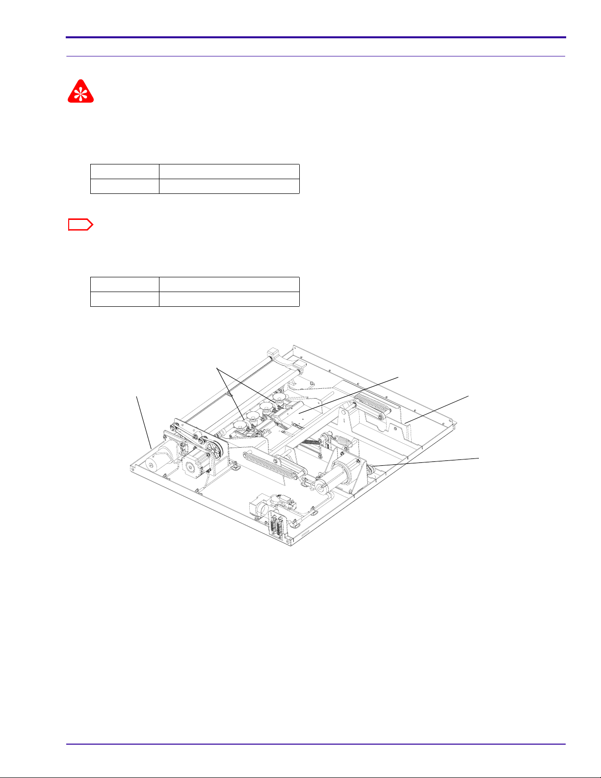
[5] Place the PICKUP AND FEED MODULE on a work surface.
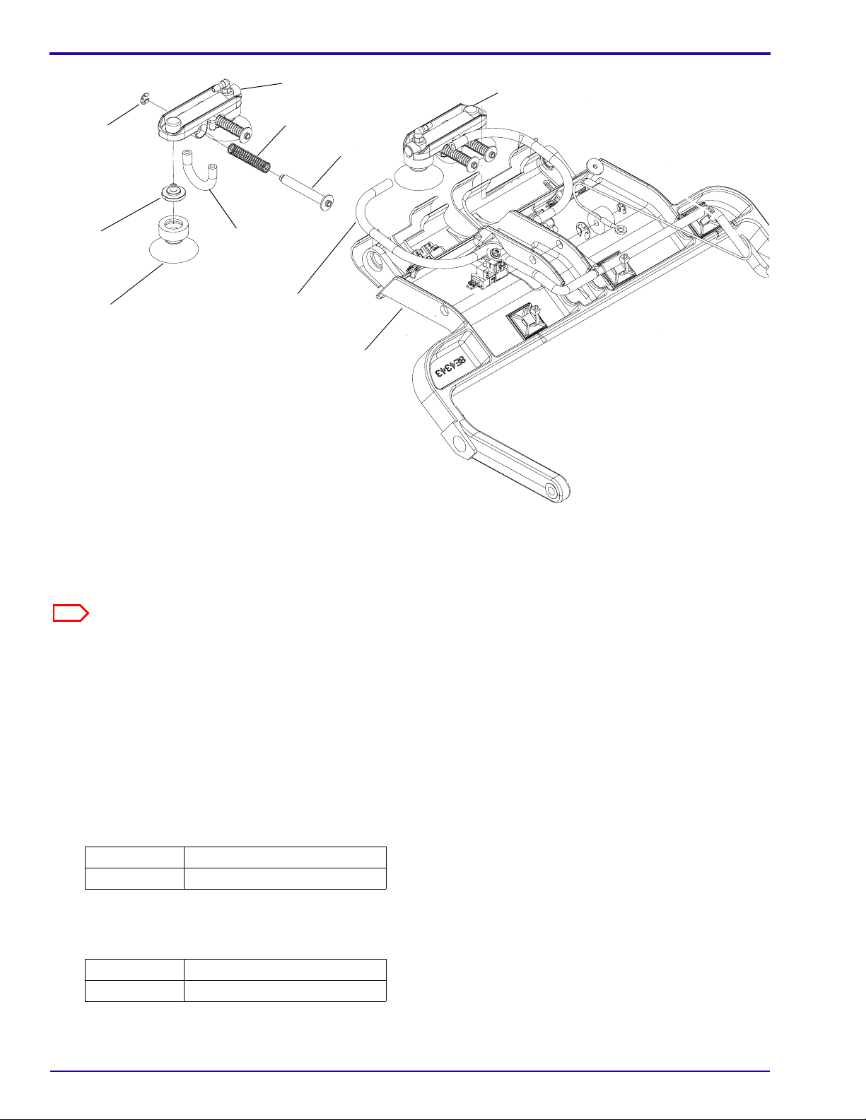
CARRIAGES
HEEL AY
PICKUP AND FEED MODULE
[6] Hold the HEEL AY down and disengage the SHIPPING LOCK.
[7] Rotate the MOTOR DRIVER ARM to move the HEEL AY to the up position.
[8] Continue to rotate the MOTOR DRIVER ARM to gain access to the 2 CARRIAGES.
SHIPPING LOCK
MOTOR DRIVER
ARM
7F3210 – 11NOV03 Rev A 3
Page 9
MODIFICATION INSTRUCTIONS, TYPE 1
2 E-RINGS
CUP SCREW
CUP
SHORT
TUBING
CARRIAGE
2 SPRINGS
2 SCREWS
LONG
TUBING
CARRIAGE
HEEL AY
[9] For each CARRIAGE AY in this PICKUP AND FEED MODULE:
(a) Remove 2 E-RINGS.
(b) Disconnect the LONG TUBING from the CARRIAGE.
(c) Remove the CARRIAGE with the other parts assembled.
Note
It is not necessary to remove the CUPS, CUP SCREWS, and SHORT TUBING from the removed CARRIAGE.
[10] Discard the removed CARRIAGES with CUPS, CUP SCREWS, and SHORT TUBING.
[11] Install 2 of the new CARRIAGES provided in the KIT.
(a) Connect the LONG TUBING to the CARRIAGE.
(b) Insert the new CARRIAGE onto the original SCREWS and SPRINGS.
(c) Install the 2 E-RINGS.
[12] Hold the HEEL AY down and rotate the MOTOR DRIVER ARM to place the HEEL AY in the down position.
[13] Engage the SHIPPING LOCK.
[14] Install the PICKUP AND FEED MODULE in the LASER IMAGER. See the ADJUSTMENTS AND
REPLACEMENTS MANUAL 8E5982.
Section Procedure
Replacements PICKUP AND FEED MODULE
[15] Do the modification procedure described above for the other 2 PICKUP AND FEED MODULES.
[16] When all PICKUP AND FEED MODULES are modified, install the ROLLBA CK MODULES and DRAWERS. See
the ADJUSTMENTS and RELACEMENTS MANUAL 8E5982.
Section Procedure
Replacements ROLLBACK MODULE
[17] Energize the LASER IMAGER.
[18] Run transport test film to check film pickup.
4 11NOV03 Rev A – 7F3210
Page 10
Completing the Modification
[1] Use the SERVICE TOOL to record “Mod 1” in the Service History Log.
[2] Record the following information for feedback.
K-number Service Code Serial No. Activity Code Installation Time
1442 M01
Publication History
Publication
Publication Date
11NOV03 7F3210 CN0004361 --- New Publication
No. ECO No.
Changed
Pages Notes
7F3210 – 11NOV03 Rev A 5
Page 11

Printed in U.S.A. • 7F3210.fm
EASTMAN KODAK COMPANY
Rochester, NY 14650
Kodak and DryView are trademarks.
HEALTH IMAGING
Page 12

Publication No. 7F3407
MAY04
RevB
MODIFICATION INSTRUCTIONS
for the
Kodak DryView 8900 LASER IMAGER
Service Code:
1442
Modification No. 02
Type 1 Selective
1. Purpose
The purpose of this Modification is to set up the Kodak DryView 8900 LASER IMAGERS to select
the Type of Cartridge, either CE Marked, Non CE Marked, and the Type of FILM, DVB, DVB+, or
DVB+ Premium, used in the IMAGER.
Note: Do this Modification during the next service call after the new FILM is available to the field.
Refer to Table 1 for the new catalogue number list.
The existing 2K RF Tag software version enables the 8900 LASER IMAGER to:
! Use only FILMS that comply with European CE marking requirements
- In European Union countries, accept only CE Marked FILMS
- In Emerging Markets/non-EU countries, accept both CE and non CE Marked FILMS
! Use only FILMS that meet the customer’s FILMS type preference
- Customers that have selected DVB+ and DVB+ Premium FILMS will have their
IMAGERS preset to use those types only.
- Customers that have selected DVB FILMS will have their IMAGERS preset to use this
type only.
The Cartridge RF Tag chip is coded differently according to Type of FILM and CE Marking.
Through the 2 K RF Tag software version, the LASER IMAGERS recognize the FILM and accept
or reject this FILM according to the LASER IMAGER setup applied by the Field Engineers.
Confidential
Restricted Information
HEALTH IMAGING
©Eastman Kodak Company, 2004
Page 13
EAMER Service Engineering will communicate when to apply the setup described in this
Modification. The activation of this setup will be made during a Next Call. We request the Field
Engineers to feedback 0.1 labor hours to Activity Code M02.
2. Prerequisite
Before you use these Modification Instructions at the customer site, verify the following:
! Type of Cartridge (CE Marked, Non CE Marked)
! Type of FILM (DVB, DVB+, DVB+ Premium)
Note: You must use the proper catalogue number at the customer site. See Table 1.
Table 1
DVB+
FILM Size
LASER
IMAGER
DVB "CE"
(blue base)
DVB+ "CE"
(higher blue
base)
DVB "non-
CE" (blue
base)
Premium
“CE”
(higher
blue base)
Description
35x43 cm 8900 135 4430 1069590 872 3132 179 9139
35x35 cm 8900 165 6511 1909746 838 4489 144 1856
35x28 cm 8900 870 5782 1495126 110 2631 106 7222
25x30 cm 8900 165 1942 1592229 128 6533 898 6663
20x25 cm 8900 154 9088 1491588 861 3424 829 1957
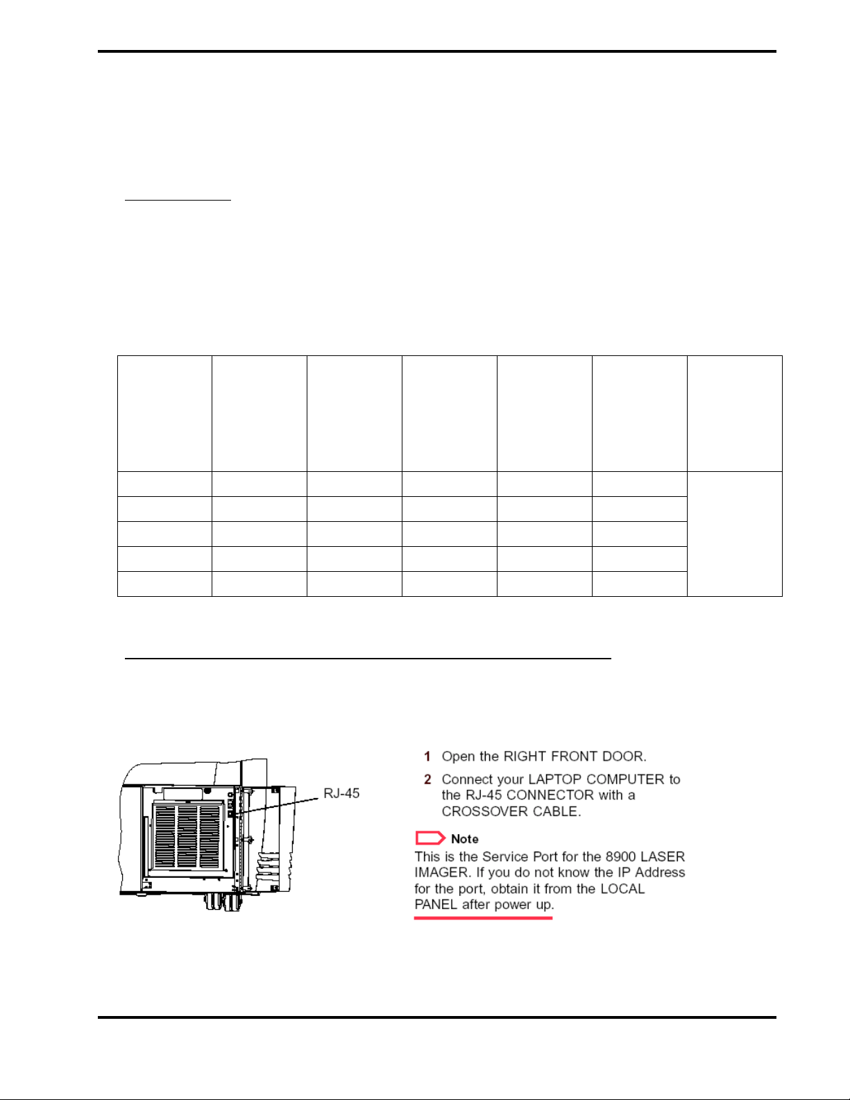
3. Setup for the Kodak DryView 8900 LASER IMAGER
3.1. Connect your Service Laptop
Connecting Your LAPTOP COMPUTER
500 sheets
package
(4 cartridges
of 125
sheets)
7F3407 – MAY04 RevB
2
Page 14
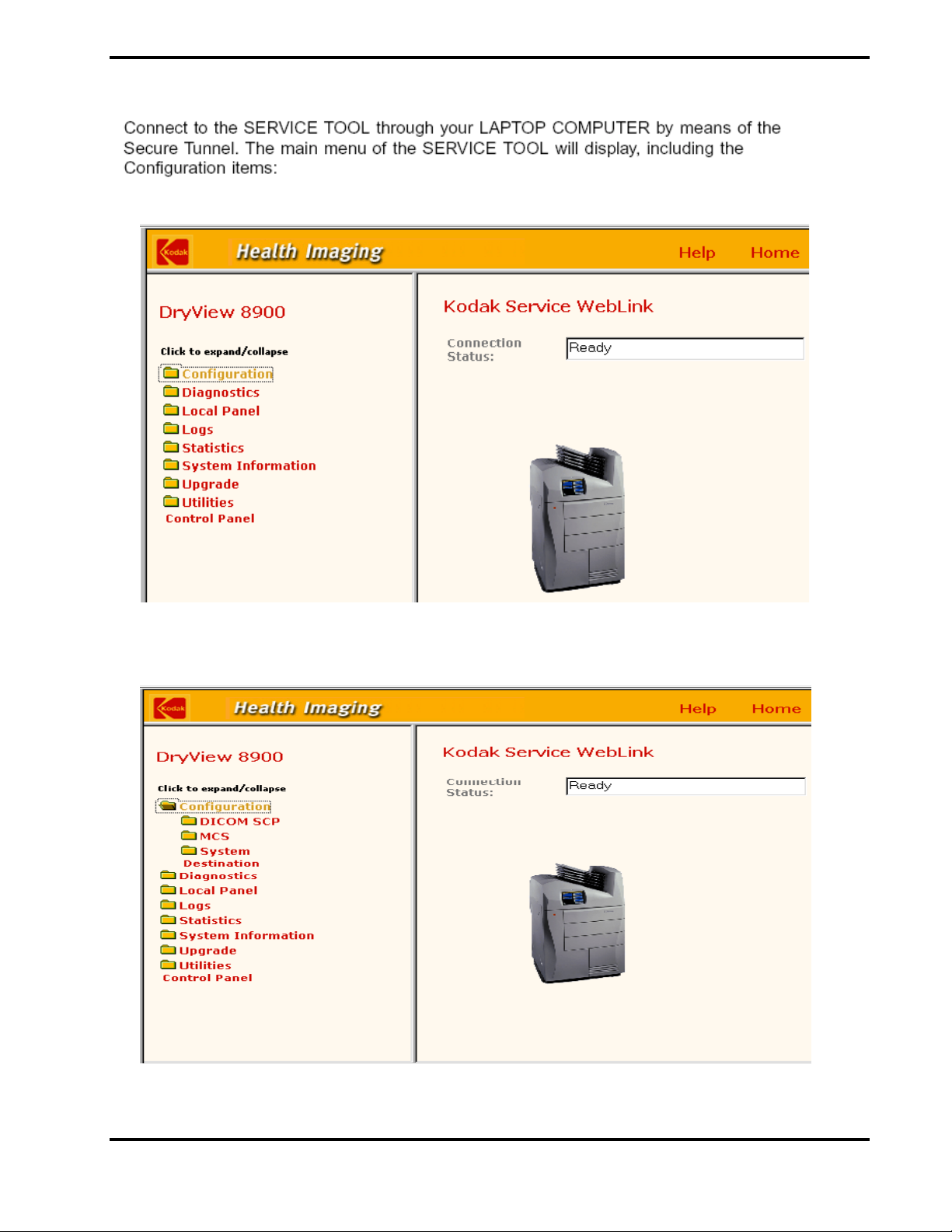
3.2. From the Main menu click on Configuration.
7F3407 – MAY04 RevB
3
Page 15
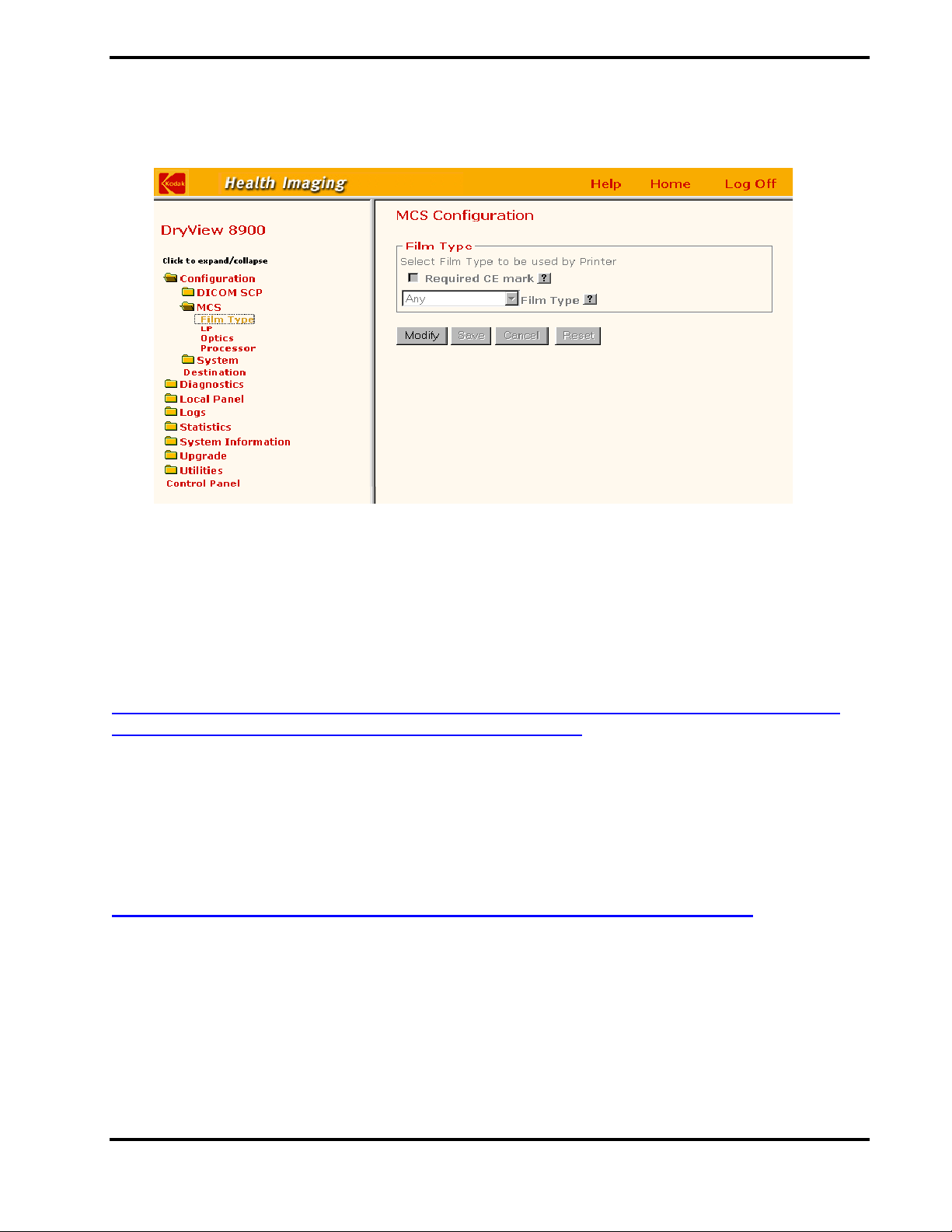
3.3. From the Configuration menu select MCS > Film Type.
3.4. Setup for “all Types of Films” and “all Types of Cartridges”
a) If “Required CE mark” box is checked, select Modify and remove the checkmark.
b) Click Save.
Note: When the “Required CE mark” box is unchecked, Any Film Type is automatically
selected.
With this setup, all FILMS and cartridges are accepted by the printer: DVB, DVB+, DVB+
Premium Films / CE Marked, Non CE Marked Cartridges.
3.5. Setup for “DVB Film and CE Marked Cartridges”
a) From the Film Type screen, click Modify and check the “Required CE mark” box.
b) From Film Type box, select Clear and Blue.
c) Click Save.
With this setup, the printer accepts only DVB FILM and CE Marked Cartridges
3.6. Setup for “DVB+ or DVB+ Premium Films and CE Marked Cartridges”
DVB+ and DVB+ Premium FILMS are always CE Marked
a) From the Film Type screen, click Modify and check the “Required CE mark” box.
b) From Film Type box, select Clear and Blue Plus.
c) Click Save.
7F3407 – MAY04 RevB
4
Page 16
With this setup, the printer accepts only DVB+ , DVB+ Premium FILMS and CE Marked
Cartridges.
3.7. Film Type Selection according to Customer Area
Follow the guidelines in Table 2.
Table 2
Area Film Cartridge
- EU Members
- Switzerland
Africa, Middle East, Eastern
Europe, Russia
`
Film Type
Usage
CE Marked DVB+
CE Marked DVB+ Follow instructions
CE Marked DVB Follow instructions
“Non CE” DVB Follow instructions
Usage
Premium
Setup for the
LASER IMAGER
Follow instructions
from paragraphs
3.1/3.2/3.3/3.6
from paragraphs
3.1/3.2/3.3/3.6
from paragraphs
3.1/3.2/3.3/3.5
from paragraphs
3.1/3.2/3.3/3.4
7F3407 – MAY04 RevB
5
Page 17

Kodak and DryView are trademarks.
7F3407 – MAY04 RevB
6
Page 18

{Modification/Type1}{Production}{HealthImaging}{ExternalAndInternal}
MODIFICATION INSTRUCTIONS
Kodak DryView 8900 LASER IMAGER
Service Code: 1442
Modification No. 3
Type 1 Selective
Purpose: To add a SORTER AY to the IMAGER.
for the
Publication No. 7F3679
03MAY04
Important
Qualified service personnel must install this modification.
Service Effects: None
Special Requirements: None
Serial Numbers: Not Applicable
Installation Time: 1.5 hours
Special Tools: • LAPTOP COMPUTER
• SERVICE TOOL with Microsoft INTERNET EXPLORER 5.5 or higher
• CROSSOVER CABLE
Parts Status: This modification is ordered through the Sales organization.
Parts Requirements: See Page 2
.
HEALTH IMAGING
Confidential
Restricted Information
© Eastman Kodak Company, 2004
Page 19
PLEASE NOTE The information contained herein is based on the experience and knowledge relating to the
subject matter gained by Eastman Kodak Company prior to publication.
No patent license is granted by this information.
Eastman Kodak Company reserves the right to change this information without notice, and
makes no warranty, express or implied, with respect to this information. Kodak sh all not be liable
for any loss or damage, including consequential or special damages, resulting from any use of
this information, even if loss or damage is caused by Kodak’s negligence or other fault.
This equipment includes parts and assemblies sensitive to damage from electrostatic
discharge. Use caution to prevent damage during all service procedures.
MODIFICATION KIT SP8919912 includes:
Part No. Description Quantity
8E4649 SORTER AY 1
7E7744 SCREW - Torx T-20, M4 x 10, metric 9
8E1969 FILM TRAY - sorter, hood 5
8E4275 EXIT TRAY POST BRACKET 1
26-1004-5503-4 WASHER - flat, 4.88 ID x 12.0 OD x 1.4T, metric 3
26-1007-2397-7 NUT - M4 x 0.7, metric 4
8E4283 BOLT - tray, sorter, hood 4
8E4596 LABEL 1
7F3679 MODIFICATION INSTRUCTIONS 1
2 03MAY04 – 7F3679
Page 20
Installing the Modification
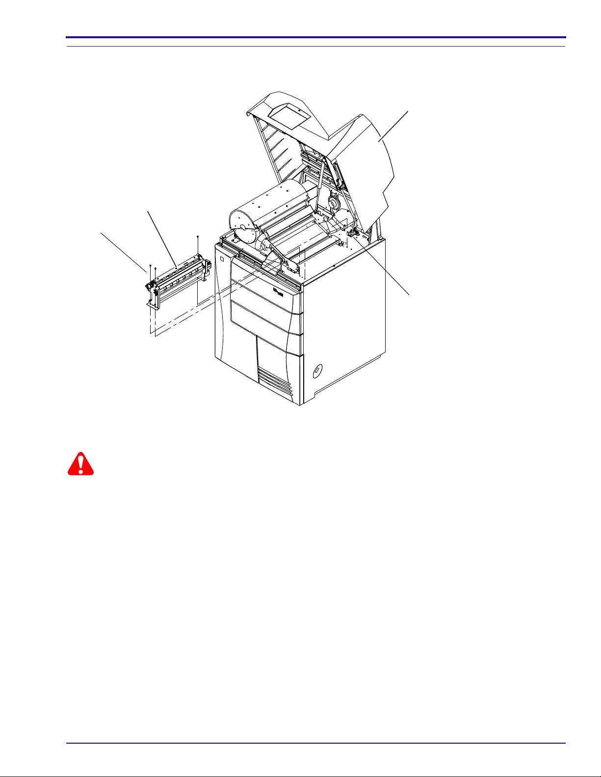
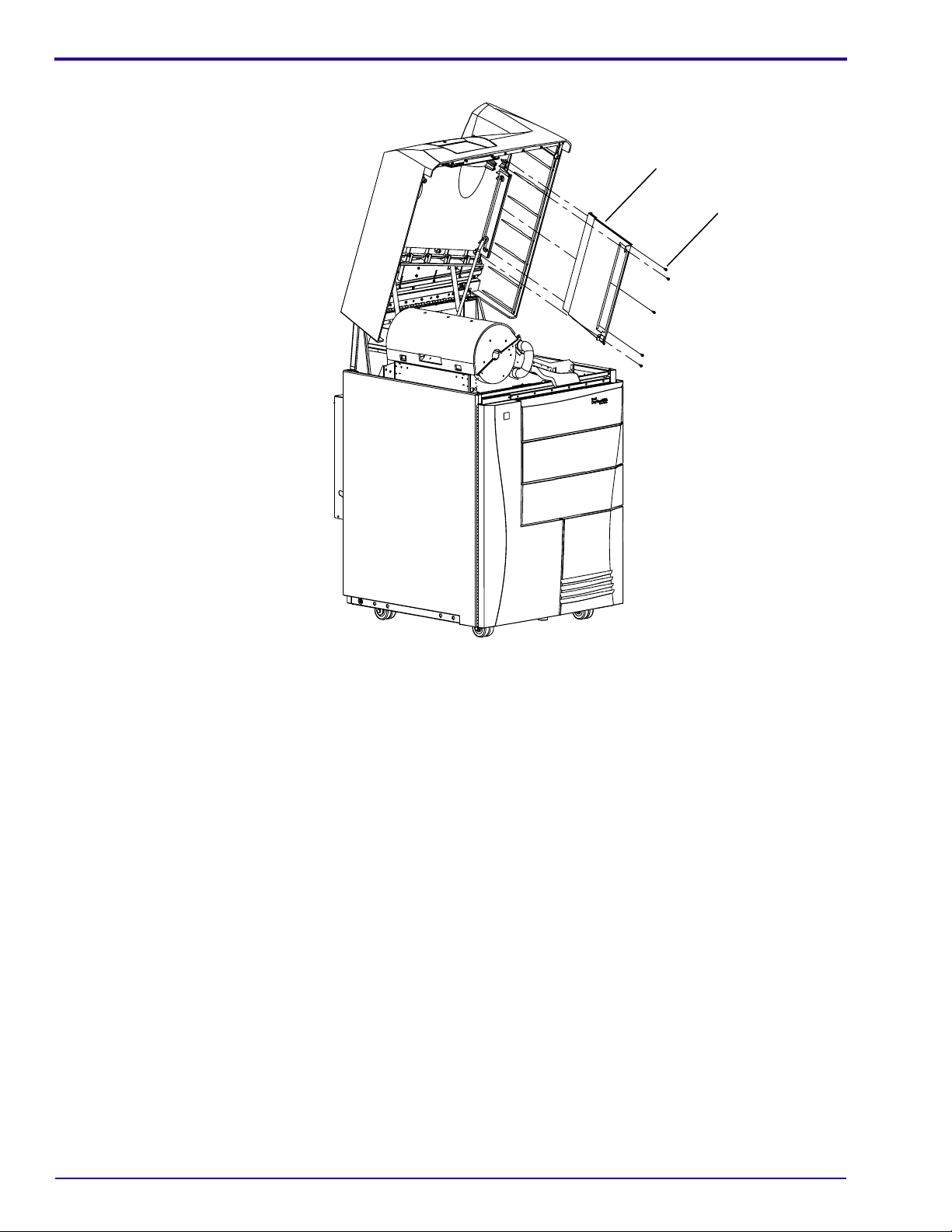
Installing the SORTER AY
TURNAROUND AY
3 SCREWS
HOOD
TURNAROUND MOTOR CABLE
H199_1501HCA
H199_1501HC
Warning
Dangerous Voltage
[1] De-energize the LASER IMAGER.
[2] Disconnect the POWER CABLE.
[3] Lift the HOOD.
[4] Disconnect the TURNAROUND MOTOR CABLE.
[5] Remove:
•3 SCREWS
• TURNAROUND AY
7F3679 – 03MAY04 3
Page 21
MODIFICATION INSTRUCTIONS, TYPE 1
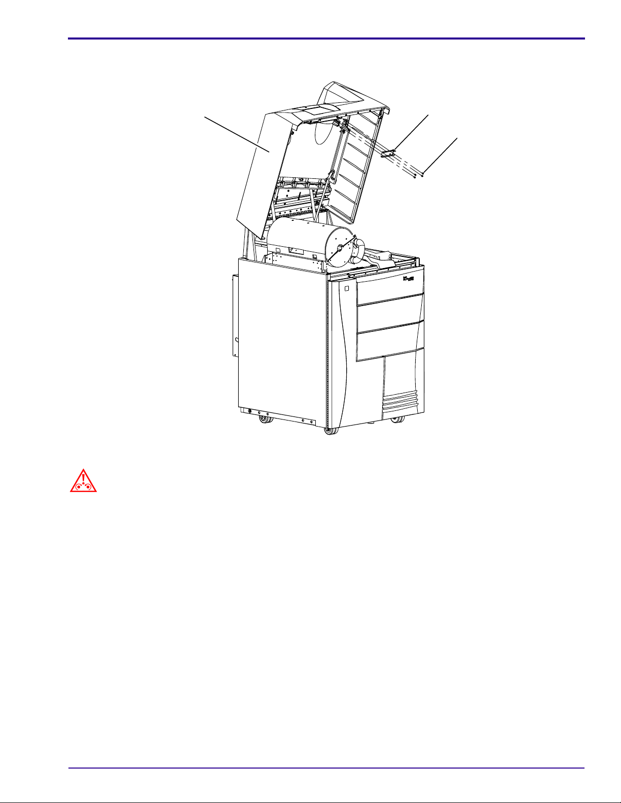
EXIT PANEL
5 SCREWS
H199_1502HCA
H199_1502HC
[6] Remove:
• 5 SCREWS
• EXIT PANEL
4 03MAY04 – 7F3679
Page 22
HOOD
EXIT TRAY POST BRACKET
4 SCREWS
H199_1503HCA
H155_1503HC
Caution
Do not tighten the SCREWS excessively.
[7] With the POST in the up position, use 4 new M4 x 10 SCREWS to install the EXIT TRAY POST BRA CKET on
the HOOD.
[8] Close the HOOD.
7F3679 – 03MAY04 5
Page 23
MODIFICATION INSTRUCTIONS, TYPE 1
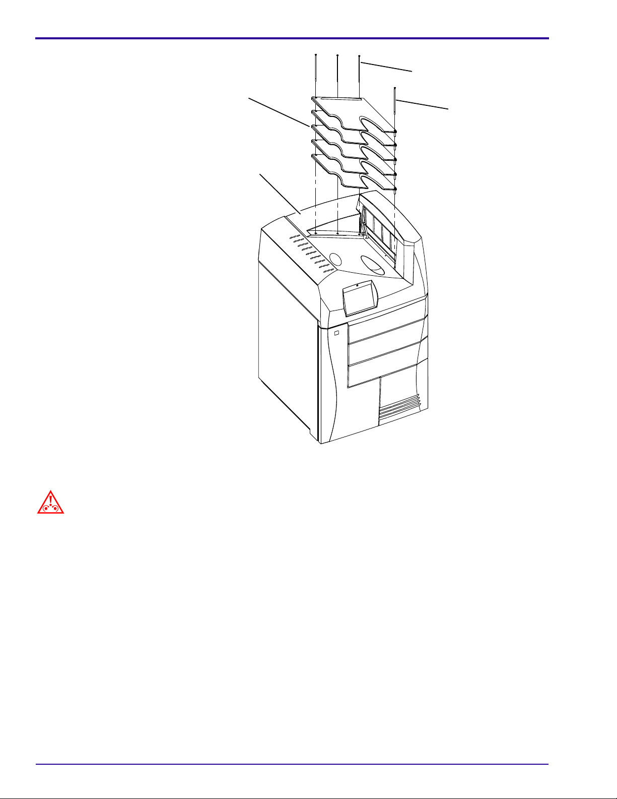
5 FILM TRAYS
3 back BOLTS
front BOLT
HOOD
H199_1504HCA
H199_1504HC
[9] Place the 5 FILM TRAYS on the HOOD.
Caution
Do not tighten the BOLTS excessively.
[10] Install:
• 3 back BOLTS - tighten from right to left
• front BOLT
6 03MAY04 – 7F3679
Page 24
H199_1505HCA
H199_1505HC
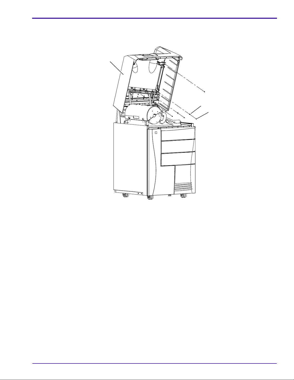
HOOD
flat WASHER
NUT
[11] Lift the HOOD.
[12] Install onto the 3 back BOLTS:
•WASHER
•NUT
[13] Install onto the front BOLT:
•WASHER
•NUT
7F3679 – 03MAY04 7
Page 25
MODIFICATION INSTRUCTIONS, TYPE 1
SORTER
CONNECTOR
SORTER AY
BASE PIN
H199_1506HCA
H199_1506HC
LOCATION
FOR SCREW B
PIN
SCREW A
SCREW C
SCREWS D and E
Important
SCREWS A through E in the following procedure are new M4 x 10 SCREWS supplied in the KIT.
[14] Partially install SCREW B in the BASE where the SORTER AY will be installed.
LATCH
FLANGE
SCREW B
Note
Do not tighten SCREW B.
[15] Position the SORTER AY on the IMAGER and slide its back FLANGE under SCREW B and into the bac k PI N.
[16] Lower the front FLANGE of the SORTER AY onto the front PIN.
[17] Install:
• SCREW A
• SCREWS D and E
[18] Pull the LATCH down.
[19] Rotate the SORTER forward.
[20] Install SCREW C.
[21] Return the SORTER to the up position.
[22] Tighten SCREW B.
[23] Connect the SORTER CONNECTOR.
8 03MAY04 – 7F3679
Page 26

FILM TRAYS
HOOD
BIN LABELS
[24] Close the HOOD.
[25] Energize the IMAGER.
[26] Install the BIN LABELS on the FILM TRAYS.
Connecting to the SERVICE TOOL
[1] Open the right FRONT DOOR.
[2] Use a CROSSOVER CABLE to connect the LAPTOP COMPUTER to the SERVICE PORT at the front of the
IMAGER.
[3] “Renew” the DHCP connection between the LAPTOP COMPUTER and the IMAGER.
For Windows 2000 or Windows NT
OPERATING SYSTEMS For Windows 98 OPERATING SYSTEMS
a. Open the DOS window.
b. Type: ipconfig /release
c. Type: ipconfig /renew
a. Select Start>Run.
b. Type: winipcfg
c. Select “network adapter”.
d. Click:
• [Release All]
• [Renew All]
Note
You can also “renew” the DHCP connection by booting your LAPTOP COMPUTER when it is set for DHCP and
connected to the IMAGER.
[4] Select Start>Programs>Kodak>SecureLink.
[5] Select the “Connect” tab.
[6] Type the correct “Server” name.
[7] Type in the “IP address” window: 192.168.0.1.
[8] Click:
• [Save Server]
• [Connect]
[9] Select Start>Programs>Kodak>Service WebLink.
7F3679 – 03MAY04 9
Page 27

MODIFICATION INSTRUCTIONS, TYPE 1
Checking the “Hardware Installed”
[1] Select Configuration>MCS>Hardware Installed.
Important
If a SORTER is installed on the IMAGER, the “Sorter Installed” box must be selected.
[2] Click [Modify].
[3] Select the “Sorter Installed” check box.
[4] Click [Save].
[5] Restart the IMAGER.
Upgrading the Software for the SORTER MICROCONTROLLER
Important
• You must do this procedure only if a “20-156” error occurred when you restarted the IMAGER. This er ror
indicates that the software on the MICRO BOARD of the SORTER AY needs to be upgraded.
• The HOOD of the IMAGER must remain closed and the IMAGER must remain energized during this pro cedure.
[1] Use “SecureLink” and the “Service WebLink” to display the SERVICE TOOL on your LAPTOP COMPUTER.
[2] From the “Main Menu” of the SERVICE TOOL, select Upgrade>Microcontrollers.
10 03MAY04 – 7F3679
Page 28

Important
• The “Version Numbers” in your IMAGER might not be the same as displayed.
• The “Micro Version” must be the same as the “MCS Version”.
[3] In each row, compare the software version identified in the “Micro Version” list with the version in the “MCS
Version” list.
[4] Place a check in the box by the name of the “Microcontroller” for all version numbers that are not the same.
[5] Click [Update].
Note
Status messages will indicate the status of the upgrade.
[6] When the upgrade completes, check that the version numbers in the 2 lists are the same.
[7] Restart the IMAGER to clear the 20-156 error.
[8] Reconnect the SERVICE TOOL.
Doing the SCP Services Configuration
[1] Have each SCU send an image to make a connection with the IMAGER.
[2] Select Configuration>DICOM SCP>SCP Services.
[3] Select “Other Option s” from the “SCP Services Configuration” screen.
[4] For each SCU, set the “Sorter Bin” parameter as follows.
Recommended
Parameter Action
“Sorter Bin” - This parameter
is available only if the
SORTER is installed.
Check with the user. Select a default exit
BIN for film processed from this SCU,
from BIN 1 through BIN 6.
For “Always Apply...”, select
YES for each SCU.
Setting
7F3679 – 03MAY04 11
Page 29

MODIFICATION INSTRUCTIONS, TYPE 1
Backing up the System Configuration
[1] From the “Main Menu” of the SERVICE TOOL, select Utilities>Backup/Restore.
[2] Click:
• [Backup]
• [Download Backup]
[3] Make a copy of the configuration on a FLOPPY DISKETTE in your LAPTOP COMPUTER.
12 03MAY04 – 7F3679
Page 30

Editing the Service History Log
[1] Select System Information>Service History.
[2] Click [Modify].
Note
The following fields on the screen are filled in automatically:
•“DateTime”
•“ServiceCode”
•“UserID”
•“UserName”
[3] Type data about the installation in the other fields.
[4] Click [Save].
[5] Check that the IMAGER and SORTER BINS operate correctly.
[6] Place the SHIPPING LABEL on the SHIPPING CONTAINER.
[7] Send the SHIPPING CONTAINER to Kodak.
Completing the Modification
[1] Record the following information for feedback:
K-number Service Code Serial No. Activity Code Installation Time Part No.
1442 M03 SP8919912
7F3679 – 03MAY04 13
Page 31

Publication History
Publication Date Publication No. ECO No. Changed Pages File Name Notes
03MAY04 7F3679 CN0004679 --- 7f3679.fm New Publication
Kodak and DryView are trademarks of Eastman Kodak Company.
Printed in U.S.A. • 7f3679.fm
EASTMAN KODAK COMPANY
Rochester, NY 14650
HEALTH IMAGING
Page 32

{Modification/Type1}{Production}{HealthImaging}{ExternalAndInternal}
MODIFICATION INSTRUCTIONS
for the
Kodak DryView 8900 LASER IMAGER
Service Code: 1442
Modification No. 4
Type 1 Selective
Purpose: To add a FILM DRAWER to the IMAGER.
Publication No. 7F3680
03MAY04
Important
Qualified service personnel must install this modification.
Service Effects: None
Special Requirements: None
Serial Numbers: Not Applicable
Installation Time: 2.0 hours
Special Tools: • LAPTOP COMPUTER
• SERVICE TOOL with Microsoft INTERNET EXPLORER 5.5 or higher
• CROSSOVER CABLE
Parts Status: This modification is ordered thrugh the Sales organization.
Parts Requirements: See Page 2
.
HEALTH IMAGING
Confidential
Restricted Information
© Eastman Kodak Company, 2004
Page 33

PLEASE NOTE The information contained herein is based on the experience and knowledge relating to the
subject matter gained by Eastman Kodak Company prior to publication.
No patent license is granted by this information.
Eastman Kodak Company reserves the right to change this information without notice, and
makes no warranty, express or implied, with respect to this information. Kodak sh all not be liable
for any loss or damage, including consequential or special damages, resulting from any use of
this information, even if loss or damage is caused by Kodak’s negligence or other fault.
This equipment includes parts and assemblies sensitive to damage from electrostatic
discharge. Use caution to prevent damage during all service procedures.
MODIFICATION KIT 1976794 includes:
Part No. Description Quantity
5E7863 ROLLBACK AY 1
5E7933 PICKUP AY 1
8E1193 LATCH AY 1
8E4829 TRACK 2
8E1200 DRAWER PANEL 1
8E4953 CABLE KIT - includes ACCESS WINDOW COVER 1
2B4081 SCREW - Torx T-20, M4 x 8, metric 6
7E7744 SCREW - Torx T-20, M4 x 10, metric 7
943600 SCREW - Torx T-20, M4 x 18, metric 4
7E9186 WASHER - Flat, 1.67 ID x 0.561, metric 4
7F3680 MODIFICATION INSTRUCTIONS 1
Note
Extra hardware is included in the MODIFICATION KIT.
2 03MAY04 – 7F3680
Page 34

Installing the Modification
Installing the SORTER AY
FRONT DOOR
VERTICAL TRANSPORT
H199_1500HCA
H199_1500HC
Warning
Dangerous Voltage
[1] De-energize the LASER IMAGER.
[2] Disconnect the POWER CABLE.
[3] Open the HOOD.
[4] Remove the right SIDE PANEL.
[5] Open the FRONT DOOR.
right SIDE PANEL
7F3680 – 03MAY04 3
Page 35

MODIFICATION INSTRUCTIONS, TYPE 1
UPPER
FRAME
LOCKING
PIN
[6] Remove the VERTICAL TRANSPORT MODULE.
(a) Remove the SCREW.
(b) Pull the VERTICAL TRANSPORT MODULE
forward approximately 3 mm (0.5 in.).
(c) Move the VERTICAL TRANSPORT
MODULE to the left to disengage it from the
LOCKING PIN.
Caution
To avoid damage to the top of the VERTICAL
TRANSPORT MODULE, do not allow it to strike the
UPPER FRAME during removal.
(d) Lift and guide the to p of th e VERTICAL
TRANSPORT MODULE under the UPPER
FRAME to remove it.
SCREW
VERTICAL TRANSPORT
MODULE
4 03MAY04 – 7F3680
Page 36

7b
1 SCREW
FALSE DRAWER FLANGE
8a
2 SCREWS
8b
2 WASHERS
8c
9b
DECORATIVE PANEL
9a
2 SCREWS
H199_1507HCA
H199_1507HC
FALSE DRAWER PANEL
7
[7] Remove the FALSE DRAWER PANEL.
(a) Remove 2 SCREWS on the right side.
(b) Remove 1 SCREW in the area of the VERTICAL TRANSPORT.
[8] Remove from the FALSE DRAWER PANEL.
(a) 2 SCREWS
(b) 2 WASHERS
(c) DECORATIVE PANEL
[9] Remove and discard:
(a) 2 SCREWS
(b) FALSE DRAWER FLANGE
7a
2 SCREWS
7F3680 – 03MAY04 5
Page 37

MODIFICATION INSTRUCTIONS, TYPE 1
2 SCREWS
DECORATIVE PANEL
DRAWER PANEL
2 SCREWS
OUTER SLIDES
ROLLBACK AY
H199_1508HCA
2 SCREWS
H199_1508HC
[10] Use 2 new M4 x 18 SCREWS and 2 new flat WASHERS to install the DECORATIVE PANEL on the new
DRAWER PANEL.
[11] Install the new right and left TRACKS for the new DRAWER AY.
(a) Position the TRACKS inside the IMAGER.
(b) Install 2 new M4 x 8 SCREWS on each TRACK.
[12] Install the new PICKUP AY.
(a) Remove the DRAWER AY located directly above the location for the new DRAWER.
(b) Check that the SHIPPING LOCK is engaged on the new PICKUP AY.
SCREW
PICKUP AY
LOCK SCREW
SCREW
K8900-26
FLANGE
6 03MAY04 – 7F3680
HEEL AY
SHIPPING LOCK
FLANGE
Page 38

(c) Install the PICKUP AY on the FRAME FLANGES.
(d) Move the PICKUP AY all the way into the IMAGER.
(e) Install and tighten 2 new M4 x 10 SCREWS.
Caution
• To avoid damage, the SHIPPING LOCK must be disengaged before po wer is applied to the IMAGER.
• To avoid injury, do not place your hands under the HEEL AY after the SHIPPING LOCK is disengaged. The
HEEL AY can drop with extreme force.
(f) Loosen the LOCK SCREW.
(g) Move the SHIPPING LOCK fully to the right.
(h) Tighten the LOCK SCREW.
[13] Install the ROLLBACK AY and DRAWER.
AY
PANEL
CAPTIVE SCREW
(a) Install the DRAWER PANEL and DECORATIVE PANEL on the DRAWER.
(b) Tighten the CAPTIVE SCREW.
Caution
• When you install the DRAWER SLIDES on the TRACKS, you must align the SLIDES correctly with the TRACKS.
• To prevent damage to the SLIDE BEARINGS, the SLIDES must be horizontal when inserted into the TRACKS.
(c) Remove the TIE-WRAP from the center of the ROLLBACK ROLLER.
(d) Carefully install the DRAWER in the TRACKS.
(e) Push the DRAWER all the wa y to the back until it is in the closed position.
7F3680 – 03MAY04 7
Page 39

MODIFICATION INSTRUCTIONS, TYPE 1
[14] Install the new DOOR LATCH AY.
DRAWER
(a) Install the LATCH AY with 3 M4 x 10 SCREWS.
Note
Do not tighten the 3 SCREWS.
(b) Adjust the position of the LATCH AY.
3 SCREWS
LATCH AY
4 mm SPACER
FLANGE
DRAWER
Force LATCH
fully back.
BYPASS RODS
1. Locate the 4 mm SPACER stored behind the right FRONT DOOR.
2. Insert the 4 mm SPACER between the DRAWER and the FLANGE.
3. Press the DRAWER in against the SPACER to lock the LATCH.
4. Use a SCREWDRIVER to press the LATCH fully to the back position.
5. Tighten the 3 SCREWS .
(c) Open and close the DRAWER 2 or 3 times to check that t he DRAWER closes properly.
(d) Route the CABLES behind the DRAWER BYPASS ROD and connect to the DRAWER INTERLOCK
SWITCH and the SOLENOID, using the existing LATCH AY as an example.
8 03MAY04 – 7F3680
Page 40

[15] Reinstall the DRAWER that was removed from above the new DRAWER.
[16] Adjust the DECORATIVE PANEL..
(a) Sight along the right side of the IMAGER to check horizontal alignment of this DRAWER with the other
DRAWER(S).
(b) Position the DECORATIVE PANEL correctly.
(c) Open the DRAWER.
Important
Do not overtighten the 2 SCREWS attaching the DECORATIVE PANEL.
(d) Tighten the 2 SCREWS with WASHERS.
[17] Install the CABLES.
CARTRIDGE CONTROLLER BOARD
SHELF
RF TAG BOARD
FRAME
large
CONNECTOR
CARTCON TO BULK HEAD
CABLE, middle or lower
CARTCON TO BULK HEAD
FEEDER CARTRIDGE CONTROLLER
CABLE, middle or lower
CARTCON TO DRAWER
CABLE, middle or lower
black LEAD WIRE
ACCESS WINDOW
COVER
2 SCREWS
Important
• The CABLE KIT includes 3 CABLES each for the middle and lower DRAWERS. The LABEL on each CABLE
identifies the CABLE.
• The large CONNECTOR must be aligned correctly.
7F3680 – 03MAY04 9
Page 41

MODIFICATION INSTRUCTIONS, TYPE 1
[18] If necessary, connect the CABLES for the middle DRAWER:
CABLE From: To:
CARTCON TO DRAWER CABLE Small CONNECTOR on
CARTRIDGE CONTROLLER BOARD
the FRAME
CARTCON TO BULK HEAD CABLE Large CONNECTOR on
CARTRIDGE CONTROLLER BOARD
the FRAME
CARTCON TO BULK HEAD FEEDER
CARTRIDGE CONTROLLER CABLE
Large CONNECTOR on
the FRAME
CARTRIDGE CONTROLLER BOARD
[19] Install 2 new M4 x 10 SCREWS to fasten the CARTCON TO DRAWER CABLE to the CONNECTOR on the
FRAME.
[20] Connect the black LEAD WIRE from the CARTCON TO DRAWER CABLE to the RF TAG BOARD.
[21] If necessary, repeat Step 18
- Step 20 for the lower DRAWER.
[22] Route the CABLES on the SHELF similar to the top DRAWER CABLES.
[23] Fasten the CABLES to the SHELF with TIE WRAPS.
[24] Install the ACCESS WINDOW COVER.
FRONT DOOR
VERTICAL TRANSPORT
H199_1500HCA
H199_1500HC
[25] Install:
• VERTICAL TRANSPORT
• right SIDE PANEL
[26] Close the FRONT DOOR.
[27] Connect the POWER CABLE.
[28] Energize the LASER IMAGER.
right SIDE PANEL
10 03MAY04 – 7F3680
Page 42

Connecting to the SERVICE TOOL
[1] Open the right FRONT DOOR.
[2] Use a CROSSOVER CABLE to connect the LAPTOP COMPUTER to the SERVICE PORT at the front of the
IMAGER.
[3] “Renew” the DHCP connection between the LAPTOP COMPUTER and the IMAGER.
For Windows 2000 or Windows NT
OPERATING SYSTEMS For Windows 98 OPERATING SYSTEMS
a. Open the DOS window.
b. Type: ipconfig /release
c. Type: ipconfig /renew
a. Select Start>Run.
b. Type: winipcfg
c. Select “network adapter”.
d. Click:
• [Release All]
• [Renew All]
Note
You can also “renew” the DHCP connection by booting your LAPTOP COMPUTER when it is set for DHCP and
connected to the IMAGER.
[4] Select Start>Programs>Kodak>SecureLink.
[5] Select the “Connect” tab.
[6] Type the correct “Server” name.
[7] Type in the “IP address” window: 192.168.0.1.
[8] Click:
•[Save Server]
• [Connect]
[9] Select Start>Programs>Kodak>Service WebLink.
Checking the “Hardware Installed”
[1] Select Configuration>MC S>Ha rdware Installed.
[2] Click [Drawers].
7F3680 – 03MAY04 11
Page 43

MODIFICATION INSTRUCTIONS, TYPE 1
Important
The check box for each DRAWER that is installed must be selected.
[3] Click [Modify].
[4] Select the check box for each DRAWER installed.
[5] Click [Save].
[6] Restart the IMAGER.
Checking IMAGER Operation
[1] Load customer film into the DRAWERS.
[2] Wait for the IMAGER to display “Ready”.
[3] Run prints from each DRAWER.
Backing up the System Configuration
[1] Re-connect to the SERVICE TOOL.
[2] From the “Main Menu” of the SERVICE TOOL, select Utilities>Backup/Restore.
[3] Click:
• [Backup]
• [Download Backup]
[4] Make a copy of the configuration on a FLOPPY DISKETTE in your LAPTOP COMPUTER.
12 03MAY04 – 7F3680
Page 44

Editing the Service History Log
[1] Select System Information>Service History.
[2] Click [Modify].
Note
The following fields on the screen are filled in automatically:
•“DateTime”
• “ServiceCode”
•“UserID”
•“UserName”
[3] Type the data about the installation in the other fields.
[4] Click [Save].
7F3680 – 03MAY04 13
Page 45

Completing the Modification
[1] Record the following information for feedback:
K-number Servic e Co de Seri al No . Activity Code I n st al la tio n Time Part No.
1442 M04 1976794
Publication History
Publication Date Publication No. ECO No. Changed Pages File Name Notes
03MAY04 7F3680 CN0004679 --- 7f3680.fm New Publication
Kodak and DryView are trademarks of Eastman Kodak Company.
Printed in U.S.A. • 7f3680.fm
EASTMAN KODAK COMPANY
Rochester, NY 14650
HEALTH IMAGING
Page 46

{Modification/Type1}{Production}{HealthImaging}{ExternalAndInternal}
Publication No. 7F3728
05MAY04
Rev A
MODIFICATION INSTRUCTIONS
for the
Kodak DryView 8900 LASER IMAGER
Service Code: 1442
Modification No. 5
Type 1 Required
Purpose: To upgrade the Kodak DryView 8900 LASER IMAGER with Version E system software, which
provides the following enhancements:
- Ability to image and process DryView Mammography Film
- Ability to configure the number of DRAWERS to be used in the IMAGER
- Ability to configure the system for use of an optional SORTER
- Ability to use an Energy Saver mode
- Ability to print images with 2 mm borders if Requested Image Size is not specified
- Ability to select D-Patch for 14 by 17 inch films. D-Patches are not used on other film sizes.
- Increases the number of film pickup attempts
- Service platform is upgraded to SecureLink version 1.2.1 and to WebLink version 1.1.b2.
Important
Qualified service personnel must install this modification.
Service Effects: None
Special Requirements: Mandatory on the next call
Serial Numbers: 890001438 and below
Installation Time: 2 hours
Special Tools: • LAPTOP COMPUTER with Microsoft INTERNET
EXPLORER 5.5 or higher
• SERVICE TOOL
• CROSSOVER CABLE
Parts Status: Available from Service Parts Management
Parts Requirements: See Page 2
HEALTH IMAGING
.
© Eastman Kodak Company, 2004
Confidential
Restricted Information
Page 47

PLEASE NOTE The information contained herein is based on the experience and knowledge relating to the
subject matter gained by Eastman Kodak Company prior to publication.
No patent license is granted by this information.
Eastman Kodak Company reserves the right to change this information without notice, and
makes no warranty, express or implied, with respect to this information. Kodak shall not be liable
for any loss or damage, including consequential or special damages, resulting from any use of
this information, even if loss or damage is caused by Kodak’s negligence or other fault.
This equipment includes parts and assemblies sensitive to damage from electrostatic
discharge. Use caution to prevent damage during all service procedures.
MODIFICATION KIT SP7F6290 includes:
Part No. Description Quantity
7F0305 System Software on CD1 and CD2 1 set
7F3728 MODIFICATION INSTRUCTIONS, Rev A 1
2 05MAY04 Rev A – 7F3728
Page 48

Installing the Modification
Updating the “SecureLink” and “WebLink” Software on Your LAPTOP COMPUTER
Important
The “SecureLink” and “WebLink” software on your LAPTOP COMPUTER must be upgraded to interface with
Release 2 of the Kodak DryView 8900 LASER IMAGER.
[1] Insert CD2 into your LAPTOP COMPUTER.
[2] Open the Compact Disk DRIVE to display the “MCS” and “Service Tool” folders.
[3] Open the “Service Tool” folder.
[4] Open the “HISP SecureLink v1.2.1.b1 CD Rev A” folder.
For Microsoft Windows 95, 98, or ME
For Microsoft Windows NT or 2000
msi
Note
Some of these files may already be installed. This will be indicated by the message: “The specified service already
exists.”
[5] Select the “exe” file that is correct for the Windows version installed in your LAPTOP COMPUTER.
(a) Double-click to start the installation process for the file.
(b) Follow the instructions on the screen to install the upgrade software.
Note
If it is necessary to remove old versions of SecureLink and WebLink, you can use “Add/Remove Programs” on the
Control Panel.
[6] Select the “Kodak SecureLink 1.2.1.msi” file.
(a) Double-click to start the installation process.
(b) Follow the instructions on the screen to install the upgrade software.
[7] Open “Weblink Client”.
[8] Select the “Kodak WebLink 1.1.b2.msi” file.
(a) Double-click to start the installation process.
(b) Follow the instructions on the screen to install the upgrade software.
[9] From the ‘Service Tool” folder, open the “SST 1.0 Rev C” file.
Note
These files may already be installed from a previous version of SecureLink.
[10] Select the “Aruniupd.exe” file.
(a) Double-click to start the installation process.
(b) Follow the instructions on the screen to install the upgrade software.
(c) If asked to restart the computer, select [No].
[11] Select the “setuppad.exe” file.
(a) Double-click to start the installation process.
(b) Follow the instructions on the screen to install the upgrade software.
(c) If asked to restart the computer, select [No].
7F3728 – 05MAY04 Rev A 3
Page 49

MODIFICATION INSTRUCTIONS, TYPE 1
[12] Select the “SST Controls.msi” file.
(a) Double-click to start the installation process.
(b) Follow the instructions on the screen to install the upgrade software.
Note
Some of the files may already be installed. This will be indicated by the message: “The specified service already
exists.”
[13] Remove CD2 from your LAPTOP COMPUTER.
[14] Restart your LAPTOP COMPUTER.
Checking the Settings for Internet Explorer on your LAPTOP COMPUTER
Important
If the configuration settings for Internet Explorer on your LAPTOP COMPUTER are not correct, the SERVICE TOOL
will not operate correctly.
[1] Open Internet Explorer on your LAPTOP COMPUTER.
[2] From the Main Menu bar, select Tools>Internet Options.
[3] Select the “Security” tab.
[4] Select the “Local Internet” icon.
[5] Click the [Custom Level] button.
[6] Under “Active X Controls and Plug-Ins”:
Function Set To
“Download signed Active X Controls” Enable
“Download unsigned Active X controls” Prompt
“Initialize and script Active X controls not marked as safe” Prompt
“Run Active X controls and plug-ins” Enable
“Script Active X controls marked safe for scripting” Enable
[7] Under “Miscellaneous”, set “Userdata persistence” to “Enable”.
[8] Select [OK].
[9] Select the “Privacy” tab.
[10] Select “Advanced”.
[11] Check “Override Automatic Cookie handling”.
[12] Set “Cookies” as follows:
Function Set to:
First Party Cookies Accept
Second Party Cookies* Accept
* With Windows 2000XP and Windows 98
OPERATING SYSTEMS, this function is “Third Party
Cookies”.
[13] Select [OK].
4 05MAY04 Rev A – 7F3728
Page 50

Installing a New Service Certificate
[1] Select Start>Programs>Kodak>SecureLink to connect the LAPTOP COMPUTER to the IMAGER.
Note
It is not necessary to do the instructions on the screen below.
[2] Click [OK].
[3] Re-install your certificate.
(a) Under the “Certificate” tab, click on [Install Certificate].
(b) On the “Install Certificate File” screen, select the file with the “CRT” extension.
(c) Click [Open].
(d) When prompted, enter your SecureLInk password.
(e) Click [OK] to complete installation of the certificate.
Renewing the DHCP Connection
Note
Before you do the system upgrade you will have to back up the system configuration. This procedure renews the
DHCP connection between your LAPTOP COMPUTER and the IMAGER to allow you to back up to your LAPTOP
COMPUTER.
[1] Use a CROSSOVER CABLE to connect the LAPTOP COMPUTER to the service port at the front of the
IMAGER.
[2] Renew the DHCP connection between the LAPTOP COMPUTER and the IMAGER as follows.
7F3728 – 05MAY04 Rev A 5
Page 51

MODIFICATION INSTRUCTIONS, TYPE 1
For Windows 2000 or Windows NT OPERATING SYSTEMS For Windows 98 OPERATING SYSTEMS
a. Open the DOS window.
b. Type ipconfig /release
c. Type ipconfig /renew
d. Continue with Connecting to the SERVICE TOOL
.
a. Select Start>Run.
b. Type winipcfg
c. Select “Network Adapter”.
d. Click:
• [Release All]
• [Renew All]
e. Continue with Connecting to the SERVICE
TOOL.
Note
You can also renew the DHCP connection by booting the laptop computer when it is set for DHCP and connected to
the IMAGER.
Connecting to the SERVICE TOOL
[1] On the LAPTOP COMPUTER, select Start>Programs>Kodak>SecureLink.
[2] Enter your SecureLink password.
[3] Click [OK].
[4] Select the “Connect” tab on the “Kodak SecureLink” screen.
[5] Type an appropriate name in the “Server” window.
[6] Ty p e 192.168.0.1 in the “IP Address” window.
[7] Click:
• [Save Server]
• [Connect]
[8] Select Start>Programs>Kodak>Service WebLink.
Capturing the Network Settings of the IMAGER
Note
You should record the network settings for the IMAGER. They may need to be re-entered after the upgrade.
[1] From the Main Menu of the SERVICE TOOL, select Configuration>System>Network to display the Host
Name and IP Address of the IMAGER.
[2] Note the Host Name and IP Address for use later in these procedures.
6 05MAY04 Rev A – 7F3728
Page 52

Backing up the System Configuration
[1] From the Main Menu of the SERVICE TOOL, select Utilities>Backup/Restore.
[2] Click the [Backup] button just above the “Status” window.
[3] Wait until “Status” indicates that Backup is complete.
[4] Click [Download Backup].
[5] Save a copy of the system configuration to a FLOPPY DISKETTE in your LAPTOP COMPUTER.
Note
The backup file will be used at the end of the upgrade procedure to restore the configuration.
[6] Close all applications.
Upgrading the DRE with New System Software - Ghosting
[1] Insert CD1 of the system software into the DVD DRIVE of the IMAGER.
Note
This CD includes the following files: BOOTCAT.BIN, BOOTIMG.BIN, and DREIMAGE.GHO.
[2] Restart the IMAGER from the LOCAL PANEL.
Note
Ghosting begins after the IMAGER boots from the DVD DRIVE. The IMAGER beeps 3 times when the procedure is
completed.
[3] Remove the CD from the DVD DRIVE.
[4] Use the POWER SWITCH to de-energize the IMAGER.
[5] Wait until the LOCAL PANEL is blank.
[6] Use the POWER SWITCH to energize the IMAGER.
Note
If the KODAK Logo remains on for longer than 5 minutes, you should use the POWER SWITCH to boot again.
[7] When the message “10-910 MCS Communications Down” appears on the LOCAL PANEL, close the error
screen.
[8] Calibrate the Touch Screen of the LOCAL PANEL.
(a) At the LOCAL PANEL, select the “Service” function.
• For User ID, type 99
• For Passcode, type 987654
(b) Select the “Calibrate Touch Screen” function.
(c) Touch [Calibration Type].
7F3728 – 05MAY04 Rev A 7
Page 53

MODIFICATION INSTRUCTIONS, TYPE 1
(d) On the “Calibration Type” screen:
• Select “7 point” calibration.
• Touch [OK].
(e) Use a STYLUS or a PEN to touch the red centers of the TARGETS that appear on the screen.
(f) Follow the instructions on the screen to complete the calibration.
(g) Touch [Apply].
(h) Touch [OK].
Upgrading the Software Applications for the MCS MASTER CPU BOARD and the MICRO BOARDS
Important
The HOOD of the IMAGER must remain closed, and the IMAGER must remain energized during this procedure. If
power is de-energized during the upgrade, the MCS MICRO could be left not stable, and a new MICRO BOARD
might have to be installed.
[1] Select Start>Settings>Control Panel>Power Options to check the power save setup for your LAPTOP
COMPUTER.
[2] Check:
• “Turn off hard disks” is set to “Never”.
• “System standby” is set to “Never” or “After 30 mins”.
[3] Click [Apply].
[4] Re-connect to the SERVICE TOOL.
[5] Select Upgrade>Application.
f
[6] Insert CD2 into the LAPTOP COMPUTER.
Note
You should check that this CD has folders named “MCS” and “Synergy Service Tool”.
[7] On the “Application Upgrade” screen, browse to and select the file in the MCS folder named
“MCS040318Micro.msi”.
Note
This file will automatically upgrade both the MASTER MCS and all the Micros on the I2C bus.
8 05MAY04 Rev A – 7F3728
Page 54

[8] Click [RUN].
Note
A sequence similar to the following begins. The messages and timing of the upgrade will vary, depending on the level
of the software that is being replaced.
• A “10-910 MCS Communications Down” message displays on the LOCAL PANEL and a status of “Printer Offline”. (You should close this error screen.)
• In approximately 30 seconds, “Upgrade in progress” displays in the Status window and “Action start” displays in
the Summary window on the SERVICE TOOL.
• In approximately 10 minutes, an “Incompatible Software Version Installed” message displays on the LOCAL
PANEL and all the cartridge icons will flash. (You should close this error screen.)
• In approximately 17 minutes, a “10-910 MCS Communications Down” message displays on the LOCAL PANEL.
(You should close this error screen.)
• In approximately 20 minutes, a “10-910 MCS Communications Down” message displays on the LOCAL PANEL.
(You should close this error screen.)
• In approximately 26 minutes, “Upgrade Completed” displays in the Summary window.
[9] Restart the IMAGER from the LOCAL PANEL.
[10] Re-establish the connection with the SERVICE TOOL.
[11] From the Main Menu of the SERVICE TOOL, select Upgrade>Microcontrollers.
[12] Compare the software version in the “Micro Version” list with the version in the “MCS Version” list.
[13] Place a mark in the check box by each Microcontroller name for which the Micro Version does not match the
MCS Version.
[14] Click [Update].
Note
Status messages will indicate the status of the upgrade.
[15] After each Micro upgrade completes, check that the numbers in the 2 Version lists are the same.
[16] Remove the CD from the DVD DRIVE in the LAPTOP COMPUTER.
7F3728 – 05MAY04 Rev A 9
Page 55

MODIFICATION INSTRUCTIONS, TYPE 1
Restoring the Configuration
[1] Select Utilities>Backup/Restore.
[2] Select “Restore” from the top of the “System Backup and Restore” screen.
[3] Place a mark in the “Upload Configuration File” check box.
[4] Click [Browse] to locate the system configuration file you downloaded to FLOPPY DISKETTE.
Note
The file extension must be .BIN.
[5] Click [Restore].
Verifying the Network Settings for the IMAGER
Note
You recorded the network settings for the IMAGER before the upgrades. These settings normally will be reset
correctly during the restoration, but they should be verified.
[1] From the Main Menu of the SERVICE TOOL, select Configuration>System>Network.
[2] Check that the network settings are correct. If they are not correct:
(a) Click [Modify].
(b) Enter the Host Name and the IP Address that you recorded in Step 10 of “Capturing the Network Settings
for the IMAGER”.
(c) Click [Save].
(d) When a message appears asking you to restart the system, click [OK].
Note
You will restart the system in a later procedure.
(e) Wait approximately 10 seconds for the configuration to take effect.
10 05MAY04 Rev A – 7F3728
Page 56

Resetting the Log Error Tally
[1] Reset the current Log Error Tally.
(a) From the Main Menu of the SERVICE TOOL, select Logs>Error Tally.
(b) Select “Current”.
(c) Click [Select All].
(d) Click [Reset].
Re-enabling the Mammo License
Important
If this upgrade procedure is a re-ghost of previously loaded Revision D or E software, the Mammo Enabled license
will not be retained, and must be enabled as follows
[1] Select Configuration>System>Software License.
Important
• The Site Key is a requirement for the Mammography upgrade.
• In the Americas, the Site Key is provided by the Technical Support Center (TSC).
• In all other areas, the Site Key is provided by the Specialists.
• The TSC or Specialist asks for the Site Code and the K-number of the IMAGER before providing the Site Key.
[2] Click [Modify].
[3] Type the Site Key information.
[4] Click [Save].
Note
Immediately after you click Save, the information in the Site Code window changes and the Site Key Window clears.
Re-enabling the Energy Save Mode (ESM)
Important
If this upgrade procedure is a re-ghost of previously loaded Revision D or E software, the Energy Save Mode (ESM)
schedule will be restored, but the ESM will not be re-enabled. Re-enable ESM as follows.
[1] From the Main Screen of the LOCAL PANEL, touch the [System Function] button.
[2] Touch the [Energy Save Schedule] button.
7F3728 – 05MAY04 Rev A 11
Page 57

[3] Touch the {Enable] button.
[4] Enter the passcode and follow the screen instructions to re-enable the ESM.
Checking Parameter Settings
[1] From the Main Menu of the SERVICE TOOL, select Utilities>Session>Restart.
[2] Re-establish the connection with the SERVICE TOOL.
[3] Select Configuration>System>Network to check that the IP Address is successfully restored.
[4] Select Configuration>DICOM SCP>SCP Services to check that the SCU configuration parameters are
restored.
Final Procedures
[1] When the LOCAL PANEL indicates that the IMAGER is Ready, check the “zone” temperatures of the
PROCESSOR. See the procedure in the ADJUSTMENTS AND REPLACEMENTS manual.
[2] If necessary, adjust the temperatures.
[3] Run test prints from each connected SCU.
[4] Check image quality of the test prints with the customer.
[5] Close the Service WebLink and the SecureLink Client.
[6] Review the updates to the User Guide that were necessary because of this upgrade. These include:
• Kodak Health Imaging and Microsoft End User License agreements have been added at the front of the
manual.
• Mammography film type/sizes are included. The available film sizes are 8 by 10 in. and 10 by 12 in. The
manual incorrectly states that 10 by 12 in. film is available. See page 2-1.
• An illustration of the new power icon screen is provided on page 3-2, showing the new Energy Save button.
• An illustration is provided on page 3-4 showing “Mammography Upgrade” which appears in the Status
screen title bar when the Mammography Upgrade is enabled.
• An illustration of the new System Functions screen is provided on page 3-8, showing the QC Step Wedge
button and the Energy Save Schedule button.
• A new procedure, “Requesting a Step Wedge,” is provided on page 3-20.
• A new key operator procedure for Scheduling the automatic energy Save Mode is provided on page 3-36.
• A New Appendix A is provided, which describes Mammography quality control procedures.
Completing the Modification
[1] Use the SERVICE TOOL to record “Mod 5” in the Service History Log.
[2] Record the following information for feedback.
K-number Service Code Serial No. Activity Code Installation Time Part No.
1442 M05 SP7F6290
Publication History
Publication
Publication Date
05MAY04 7F3728 CN0004917 --- New Publication
Printed in U.S.A. • 7F3728.fm
No. ECO No.
Kodak and DryView are trademarks of Eastman Kodak Company.
EASTMAN KODAK COMPANY
Rochester, NY 14650
Changed
Pages Notes
HEALTH IMAGING
Page 58

{Modification/Type2}{Production}{HealthImaging}{ExternalAndInternal}
Publication No. 7F3928
25MAR04
MODIFICATION INSTRUCTIONS
for the
Kodak DryView 8900 LASER IMAGER
Service Code: 1442
Modification No. 6
Type 1 Selective
Purpose: To enable the Mammography feature and film type of a Kodak DryView 8900 LASER IMAGER.
Important
Qualified service personnel must install this modification.
Service Effects: None
Special Requirements: The IMAGER must have Release 2, Rev D or higher
system software.
Serial Numbers: All
Installation Time: 1.5 hours
Special Tools • LAPTOP COMPUTER
• SERVICE TOOL with Microsoft INTERNET
EXPLORER version 5.5 or higher
• CROSSOVER CABLE
• INSTALLATION INSTRUCTIONS for the Kodak
DryView 8900 LASER IMAGER 8E5986
• USER GUIDE for the Kodak DryView 8900 LASER
IMAGER, Rev C, 5E6155
Parts Status: None
Parts Requirements: See Page 2
.
HEALTH IMAGING
Confidential
Restricted Information
© Eastman Kodak Company, 2004
Page 59

PLEASE NOTE The information contained herein is based on the experience and knowledge relating to the
subject matter gained by Eastman Kodak Company prior to publication.
No patent license is granted by this information.
Eastman Kodak Company reserves the right to change this information without notice, and
makes no warranty, express or implied, with respect to this information. Kodak sh all not be liable
for any loss or damage, including consequential or special damages, resulting from any use of
this information, even if loss or damage is caused by Kodak’s negligence or other fault.
This equipment includes parts and assemblies sensitive to damage from electrostatic
discharge. Use caution to prevent damage during all service procedures.
MODIFICATION KIT SP7F6030 includes:
Part No. Description Quantity
7F3928 MODIFICATION INSTRUCTIONS 1
2 25MAR04 – 7F3928
Page 60

Installing the Modification
Warning
Dangerous Voltage
[1] Connect the LAPTOP COMPUTER to the service port. Use the CROSSOVER CABLE.
[2] What is the Microsoft OPERATING SYSTEM?
Microsoft Windows 98
Microsoft Windows 2000 or Windows NT
OPERATING SYSTEMS
a. Open the DOS window.
b. Type: ipconfig/release
c. Type: ipconfig/renew
d. Continue with Step 3
.
Note
You can also make the DHCP connection when the LAPTOP COMPUTER is set for DHCP and connected to the
IMAGER.
[3] Select Start>Programs>Kodak>Secure Link.
[4] Select the “Connect” tab.
[5] Type the “Server” name.
[6] At the “IP address” window, type 192.168.0.1
[7] Click:
•[Save Server]
• [Connect]
[8] Select Start>Programs>Kodak>Service WebLink>Configuration>System>Software License.
OPERATING SYSTEM
a. Select Start>Run.
b. Type: winipcfg
c. Select “Network Adapter”.
d. Click:
• [Release All]
• [Renew All]
e. Continue with Step 3
.
7F3928 – 25MAR04 3
Page 61

MODIFICATION INSTRUCTIONS, TYPE 2
Important
• The “Site Key” is a requirement for the Mammography upgrade.
• In the Americas, the “Site Key” is provided by the Technical Support Center (TSC).
• In all other areas, the “Site Key” is provided by the Specialists.
• The TSC or Specialist asks for the “Site Code” and the K-number of the IMAGER before providing the “Site Key”.
[9] Click [Modify].
[10] Type the “Site Key” information.
[11] Click [Save].
Note
The information in the “Site Code” window changes and the “Site Key” window clears.
[12] Do a shutdown and then restart the IMAGER.
[13] Load the Kodak DryView MAMMOGRAPHY LASER IMAGING FILM into the IMAGER.
[14] Connect the SERVICE TOOL.
[15] Ask each MAMMOGRAPHY SCU to send an image to the IMAGER.
[16] Do the configuration procedure for each SCU. See INSTALLATION INSTRUCTIONS 8E5986.
Section Procedure
Installation Doing the SCP Services
4 25MAR04 – 7F3928
Page 62

Important
The modification is not complete until you set the film base type and check the “Always Apply” check box.
[17] Select:
• Configuration>DICOM>SCP Services>Other Options>Film Base
• “MAMMO BLUE FILM” check box
• “YES” in the “ALWAYS APPLY?” check box
Completing the Modification
[1] Load another MAMMOGRAPHY LASER IMAGING FILM in the IMAGER.
[2] Run a Baseline test. See INSTALLATION INSTRUCTIONS 8E5986:
Section Procedure
Installation Running a QC Baseline Test - Mammography
[3] Ask that a Mammography clinical image be sent to the IMAGER.
[4] Ask the “Responsible Health Care Professional” at the site for an approval of the image result.
[5] From the Main Menu of the SERVICE TOOL, select Utilities>Backup/Restore.
[6] Click:
•[Backup]
• [Download Backup]
[7] Record a copy of the information to a FLOPPY DISKETTE in your LAPTOP COMPUTER.
7F3928 – 25MAR04 5
Page 63

[8] Select System Information> Service History.
[9] Click [Modify].
Note
The system automatically enters: “DateTime”, “ServiceCode”, “UserID”, and “UserName”.
[10] Type the remaining installation data in the other fields.
[11] Click [Save].
[12] Review the following procedures with the operator. See the USER GUIDE for the Kodak DryView 8900 LASER
IMAGER, Rev C, 5E6155.
Section Procedure
Appendix A Quality Control Procedures
[13] Record the information for feedback:
K-number Service Code Serial No. Activity Code Installation Time Part No.
1442 M06 1.5 SP7F6030
Publication History
Publication
Date Publication No. ECO No. Changed Pages File Name Notes
25MAR04 7F3928 CN0004740 - - - 7f3928.fm New Publication
Kodak and DryView are trademarks of Eastman Kodak Company.
Printed in U.S.A. • 7F3928.fm
EASTMAN KODAK COMPANY
Rochester, NY 14650
HEALTH IMAGING
Page 64

{Modification/Type1}{Production}{HealthImaging}{ExternalAndInternal}
Publication No. 7F3983
16MAR04
Rev A
MODIFICATION INSTRUCTIONS
for the
Kodak DryView 8900 LASER IMAGER
Service Code: 1442
Modification No. 7
Type 1 Required
Purpose: To modify the PROCESSOR CONTROL BOARD with HEAT SINKS on the SOLID STATE RELAYS.
Important
Qualified service personnel must install this modification.
Service Effects: None
Special Requirements: Mandatory on the next call
Serial Numbers: 890001188 and below
Installation Time: 0.5 hour
Special Tools:
Parts Status: Available from Service Parts Management
Parts Requirements: See Page 2.
HEALTH IMAGING
Confidential
Restricted Information
© Eastman Kodak Company, 2004
Page 65

PLEASE NOTE The information contained herein is based on the experience and knowledge relating to the
subject matter gained by Eastman Kodak Company prior to publication.
No patent license is granted by this information.
Eastman Kodak Company reserves the right to change this information without notice, and
makes no warranty, express or implied, wit h respect to this information. Kodak sh all not be liable
for any loss or damage, including consequential or special damages, resulting from any use of
this information, even if loss or damage is caused by Kodak’s negligence or other fault.
This equipment includes parts and assemblies sensitive to damage from electrostatic
discharge. Use caution to prevent damage during all service procedures.
MODIFICATION KIT 7F3996 includes:
Part No. Description Quantity
7F3974 HEAT SINKS with TAPE 3
7F3983 PROCESSOR CONTROL BOARD
Modification No. 7
1
2 16MAR04 Rev A – 7F3983
Page 66

Installing the Modification
Removing the PROCESSOR CONTROL BOARD
[1] To de-energize the IMAGER from the LOCAL PANEL, touch:
• The “power” icon
• {Shut Down]
Warning
Dangerous Voltage
[2] Disconnect the POWER CORD.
[3] Open the BACK DOOR.
PROCESSOR CONTROL
BOARD
[4] Locate the PROCESSOR CONTROL BOARD.
4 CONNECTORS
5 SCREWS
[5] Disconnect the 4 CONNECTORS, J1 - J4.
[6] Remove the 5 SCREWS.
[7] Remove the BOARD.
7F3983 – 16MAR04 Rev A 3
Page 67

MODIFICATION INSTRUCTIONS, TYPE 1
Installing the HEAT SINKS
HEAT SINK
TRANSFORMER
3 SOLID STATE RELAYS (SSR)
Important
There are 3 SOLID STATE RELAYS (SSRs) mounted on the PROCESSOR CONTROL BOARD.
[1] Carefully move the REAR SSR away from the TRANSFORMER.
HEAT SINK
RELEASE LINER
[2] Remove the RELEASE LINER from the HEAT SINK.
[3] Position the HEAT SINK on the flat side of the SSR.
[4] Press the HEAT SINK firmly to the flat side of the SSR.
Caution
Use caution not to crack the EPOXY CASE on the SSR.
[5] Bend only the SIDE TABS around the SSR.
REAR SSR
TRANSFORMER
[6] Repeat Step 1
through Step 5 for the next 2 SSRs.
[7] Move the SSRs and HEAT SINKS so that they are all separated as much as possible.The REAR SSR should
be close but not touching the TRANSFORMER..
4 16MAR04 Rev A – 7F3983
Page 68

Installing the PROCESSOR CONTROL BOARD
[1] Reverse the steps in the removal procedure.
[2] Energize the IMAGER.
Completing the Modification
[1] Use the SERVICE TOOL to record “Mod 7” in the Service History Log.
[2] Record the following information for feedback.
K-number Service Code Serial No. Activity Code Installation Time Part No.
1442 M07 7F3996
7F3983 – 16MAR04 Rev A 5
Page 69

Publication History
Publication
Publication Date
16MAR04 7F3983 CN0004723 --- New Publication
No. ECO No.
Changed
Pages Notes
Printed in U.S.A. • 7F3983.fm
EASTMAN KODAK COMPANY
Rochester, NY 14650
Kodak and DryView are trademarks.
HEALTH IMAGING
Page 70

{Modification/Type1}{Production}{HealthImaging}{ExternalAndInternal}
Publication No. 7F6268
05MAY04
MODIFICATION INSTRUCTIONS
for the
Kodak DryView 8900 LASER IMAGER
Service Code: 1442
Modification No. 8
Type 1 Selective
Purpose: To eliminate ground noise in the IMAGING AY that caus es pa r ity erro rs 27 -9 1 2 an d 27 -9 1 4. The
modification includes installation of 2 ISOLATION GASKETS between the IMAGING CABLES and
the CABLE SUPPORT BRACKET and installation of a new FLEX TERMINATION BOARD with
modified ground circuits.
Important
Qualified service personnel must install this modification.
Service Effects: None
Special Requirements: None
Serial Numbers: This modification applies to all IMAGERS experiencing parity errors 27-912 and 27-914.
Installation Time: 1 hour
Special Tools: • LAPTOP COMPUTER
• SERVICE TOOL with Microsoft INTERNET EXPLORER 5.5 or higher
• CROSSOVER CABLE
Parts Status: Available from Service Parts Management.
Parts Requirements: See Page 2
.
HEALTH IMAGING
Confidential
Restricted Information
© Eastman Kodak Company, 2004
Page 71

PLEASE NOTE The information contained herein is based on the experience and knowledge relating to the
subject matter gained by Eastman Kodak Company prior to publication.
No patent license is granted by this information.
Eastman Kodak Company reserves the right to change this information without notice, and
makes no warranty, express or implied, with respect to this information. Kodak sh all not be liable
for any loss or damage, including consequential or special damages, resulting from any use of
this information, even if loss or damage is caused by Kodak’s negligence or other fault.
This equipment includes parts and assemblies sensitive to damage from electrostatic
discharge. Use caution to prevent damage during all service procedures.
PLATEN ISOLATION GASKET MODIFICATION KIT SP7F6191 includes:
Part No. Description Quantity
8E4986 ISOLATION GASKE T, Long 1
8E4987 ISOLATION GASKE T, Short 1
8E1567 FLEX TERMINATION BOARD 1
7F6268 MODIFICATION INSTRUCTIONS 1
2 05MAY04 – 7F6268
Page 72

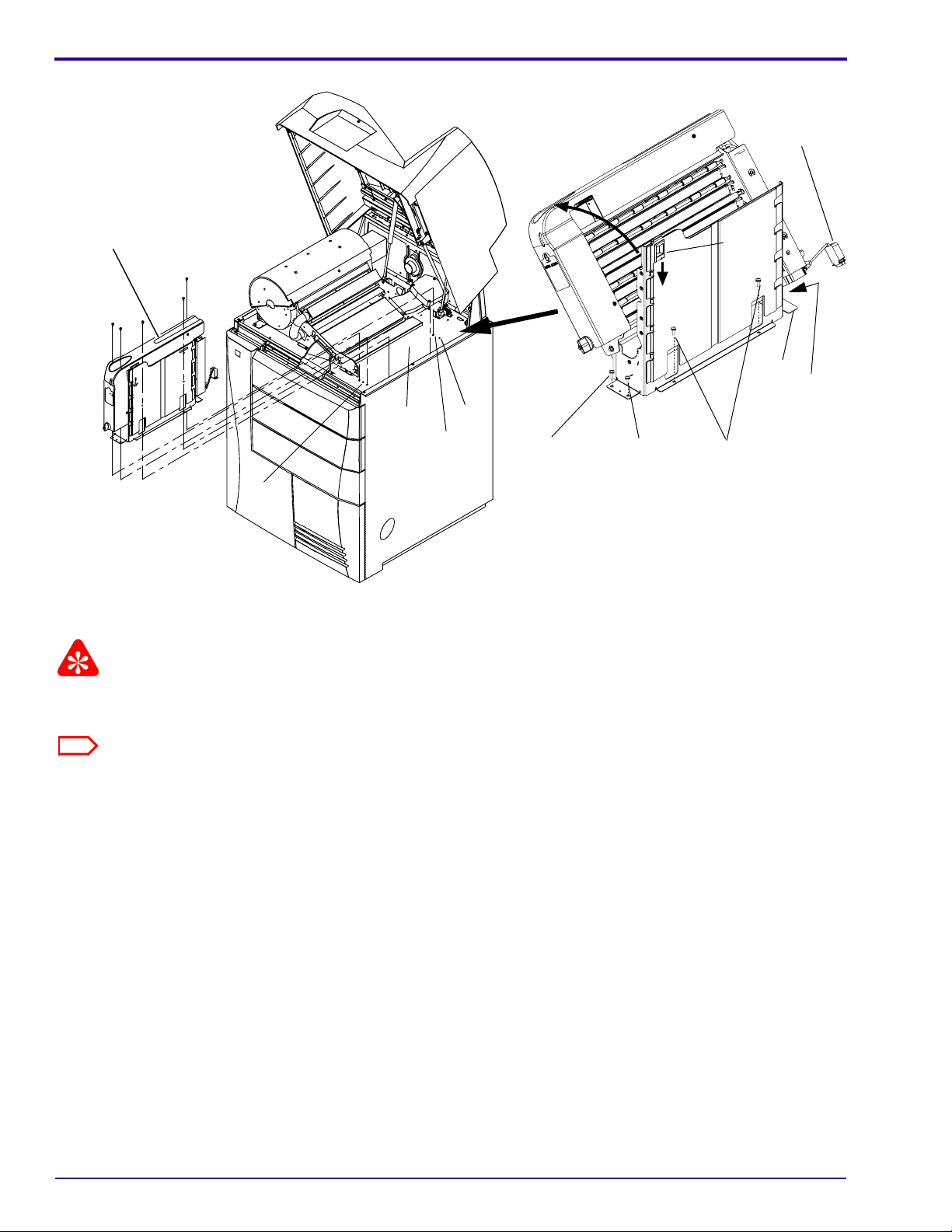
Installing the Modification
Warning
Dangerous Voltage
[1] De-energize the LASER IMAGER.
[2] Disconnect the POWER CABLE.
[3] Extend the IMAGING AY.
(a) Open the BACK DOOR.
3 CABLES
2 SCREWS
(b) Remove:
•3 CABLES
•2 SCREWS
(c) Open the left FRONT DOOR.
(d) Pull out the IMAGING AY.
[4] Install the 2 ISOLATION GASKETS.
CABLE CLAMP
IMAGING CABLES
long ISOLATION GASKET short ISOLATION GASKETCABLE SUPPORT BRACKET
(a) Peel the LINER from the long ISOLATION GASKET.
(b) Install the long ISOLATION GASKET on the CABLE SUPPORT BRACKET.
7F6268 – 05MAY04 3
Page 73

MODIFICATION INSTRUCTIONS, TYPE 1
(c) Open one of the CABLE CLAMPS attached to the CABLE SUPPORT BRACKET.
Note
The CABLES are precisely positioned by the 2 CABLE CLAMPS. If you open both CABLE CLAMPS, you may lose
the positioning. If you find it necessary to open both CLAMPS to install the GASKET, first mark the top CABLE beside
one of the CLAMPS so the CABLES can be returned to their original position.
(d) Peel the LINER from the short ISOLATION GASKET.
(e) Lift the IMAGING CABLES and install the short ISOLATION GASKET on the CABLE SUPPORT
BRACKET between the 2 CABLE CLAMPS.
(f) Close the CABLE CLAMP(S).
[5] Push the IMAGING AY back into the IMAGER.
[6] Remove the FLEX TERMINATION BOARD from the back of the IMAGING AY.
COVER
4 SCREWS
4 SCREWS
3 PLUGS
FLEX TERMINATION
BOARD
IMAGER CABLE
CONNECTORS
(a) Remove:
• 4 SCREWS
• COVER
(b) Remove 3 PLUGS from the bottom of the FLEX TERMINATION BOARD.
(c) Remove 4 SCREWS.
(d) Pull the FLEX TERMINATION BOARD forward to gain access to the flat IMAGER CABLES.
(e) Disconnect the 2 IMAGER CABLES from the back of the FLEX TERMINATION BOARD.
ESD
Possible damage from electrostatic discharge.
[7] Wearing a WRIST STRAP, install the new FLEX TERMINATION BOARD in reverse order of the procedure in
Step 6 above.
4 05MAY04 – 7F6268
Page 74

[8] Reconnect the 3 CABLES to the back of the IMAGING AY.
[9] Install the 2 SCREWS.
[10] Close the BACK DOOR.
[11] Close the left FRONT DOOR.
Checking Operation of the IMAGER
Warning
Dangerous Voltage
[1] Re-connect the POWER CORD.
[2] Energize the IMAGER.
[3] Allow the IMAGER to warm to the READY state.
[4] Run test prints to check operation of the IMAGER.
3 CABLES
2 SCREWS
7F6268 – 05MAY04 5
Page 75

MODIFICATION INSTRUCTIONS, TYPE 1
Connecting to the SERVICE TOOL
[1] Open the right FRONT DOOR.
[2] Use a CROSSOVER CABLE to connect the LAPTOP COMPUTER to the SERVICE PORT of the IMAGER.
[3] “Renew” the DHCP connection between the LAPTOP COMPUTER and the IMAGER.
For Windows 2000 or Windows NT
OPERATING SYSTEMS For Windows 98 OPERATING SYSTEMS
a. Open the DOS window.
b. Type: ipconfig /release
c. Type: ipconfig /renew
Note
You can also “renew” the DHCP connection by booting your LAPTOP COMPUTER when it is set for DHCP and
connected to the IMAGER.
[4] Select Start>Programs>Kodak>SecureLink.
[5] Select the “Connect” tab.
[6] Type the correct “Server” name.
[7] Type in the “IP address” window: 192.168.0.1.
[8] Click:
• [Save Server]
• [Connect]
[9] Select Start>Programs>Kodak>Service WebLink.
a. Select Start>Run.
b. Type: winipcfg
c. Select “network adapter”.
d. Click:
• [Release All]
• [Renew All]
6 05MAY04 – 7F6268
Page 76

Editing the Service History Log
[1] Select System Information>Service History.
[2] Click [Modify].
Note
The following fields on the screen are filled in automatically:
•“DateTime”
• “ServiceCode”
•“UserID”
•“UserName”
[3] Type data about the installation in the other fields.
[4] Click [Save].
7F6268 – 05MAY04 7
Page 77

Completing the Modification
[1] Record the following information for feedback:
K-number Servic e Co de Seri al No . Activity Code I n st al la tio n Time Part No.
1442 M08 SP7F6191
Publication History
Publication Date Publication No. ECO No. Changed Pages File Name Notes
05MAY04 7F6268 CN0004846 --- 7f6268.fm New Publication
Kodak and DryView are trademarks of Eastman Kodak Company.
Printed in U.S.A. • 7f6268.fm
EASTMAN KODAK COMPANY
Rochester, NY 14650
HEALTH IMAGING
Page 78

{Modification/Type1}{Production}{HealthImaging}{ExternalAndInternal}
Publication No. 8F0115
18AUG04
MODIFICATION INSTRUCTIONS
for the
Kodak DryView 8900 LASER IMAGER
Service Code: 1442
Modification No. 9
Type 1 Required - Japan Only
Purpose: To install a new PROCESSOR CONTROL BOARD that has SOLID STATE RELAYS with higher
current capacity.
Important
Qualified service personnel must install this modification.
Service Effects: None
Special Requirements: Mandatory on the next call
Serial Numbers: 890001485 and below
Installation Time: 0.5 hour
Special Tools:
Parts Status: Available from Service Parts Management
Parts Requirements: See Page 2.
HEALTH IMAGING
Confidential
Restricted Information
© Eastman Kodak Company, 2004
Page 79

PLEASE NOTE The information contained herein is based on the experience and knowledge relating to the
subject matter gained by Eastman Kodak Company prior to publication.
No patent license is granted by this information.
Eastman Kodak Company reserves the right to change this information without notice, and
makes no warranty, express or implied, wit h respect to this information. Kodak sh all not be liable
for any loss or damage, including consequential or special damages, resulting from any use of
this information, even if loss or damage is caused by Kodak’s negligence or other fault.
This equipment includes parts and assemblies sensitive to damage from electrostatic
discharge. Use caution to prevent damage during all service procedures.
MODIFICATION KIT SP8F0124 includes:
Part No. Description Quantity
SP7F3360 PROCESSOR CONTROL BOARD 1
2 18AUG04 – 8F0115
Page 80

Installing the Modification
Removing the PROCESSOR CONTROL BOARD
[1] To de-energize the IMAGER from the LOCAL PANEL, touch:
• The “power” icon
• {Shut Down]
Warning
Dangerous Voltage
[2] Disconnect the POWER CORD.
[3] Open the BACK DOOR.
PROCESSOR CONTROL
BOARD
[4] Locate the PROCESSOR CONTROL BOARD.
4 CONNECTORS
5 SCREWS
[5] Disconnect the 4 CONNECTORS, J1 - J4.
[6] Remove the 5 SCREWS.
[7] Remove the BOARD.
8F0115 – 18AUG04
Page 81

Installing the PROCESSOR CONTROL BOARD
[1] Reverse the steps in the removal procedure.
Note
It might be necessary to cut the TIE WRAP holding the J3 (PROCESSOR COMMUNICATIONS) HARNESS to allow
the new PROCESSOR CONTROL BOARD to position correctly.
[2] Energize the IMAGER.
[3] If a 20-156 error occurs, indicating that the software is not compatible, upgrade the software in the new
PROCESSOR CONTROL BOARD. See ADJUSTMENTS and REPLACEMENTS 8E5982:
Section Procedure
Replacements Upgrading the “Microcontroller” Application when a
New MICRO BOARD is Installed
Completing the Modification
[1] Use the SERVICE TOOL to record “Mod 9” in the Service History Log.
[2] Record the following information for feedback.
K-number Service Code Serial No. Activity Code Installation Time Part No.
1442 M09 SP8F0124
Publication History
Publication
Publication Date
18AUG04 8E0115 CN0005263 --- New Publication
No. ECO No.
Changed
Pages Notes
Kodak and DryView are trademarks of the Eastman Kodak Company.
Printed in U.S.A. • 8f0115.fm
EASTMAN KODAK COMPANY
Rochester, NY 14650
HEALTH IMAGING
 Loading...