

Page 1

7 X 9 inside cover
Kodak DryView 8600 Laser Imaging System /
for Mammography
User Guide
8186546
74-0401-6533-9
3/00 Rev. B
Page 2
Classification, Warnings, and Cautions
Classification, Warnings, and Cautions
for DryView 8600 Laser Imager
Read and understand all instructions before using.
Classifications
UL Classified
File Number E163816
Control Number 48VF
Medical Equipment
UL 2601-1 CAN/CSA No. 601.1
!
Classified by Underwriters Laboratories Inc. With Respect to Electric Shock,
Fire, Casualty and Medical Hazards only in Accordance with UL 2601-1, CAN/CSA
C22.2 No. 601.1 and IEC 601.1.
!
WARNING
This equipment is operated with hazardous voltage which can shock,
burn, or cause death.
Remove wall plug before servicing equipment. Never pull on cord to remove from
outlet. Grasp plug and pull to disconnect.
Do not operate equipment with a damaged power cord.
Do not use an extension cord to power this equipment.
Use only the power cord supplied with the equipment.
Position the power cord so it will not be tripped over or pulled.
Connect this equipment to a grounded outlet.
!
WARNING
Not protected against ingress of liquids, including bodily fluids.
!
WARNING
For continued protection against fire, replace fuses only with fuses of the same type
and rating.
2000 March Rev. B 8186546
i
Page 3

DryView 8600 User Guide
Classification, Warnings, and Cautions
for DryView 8600 Laser Imager (continued)
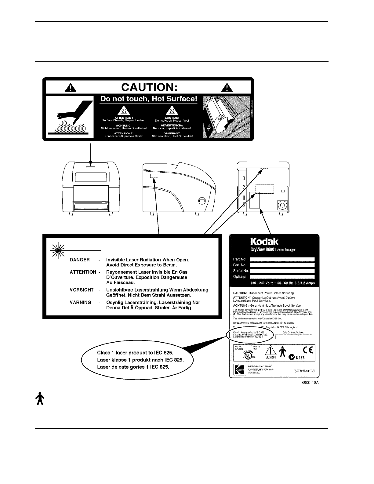
Avoid touching the developer drum when removing film jams from the imager. The
developer drum may become hot during extended imager operation.
!
CAUTION
This equipment has been tested and found to comply with the limits for a Class B
digital device, pursuant to part 15 of the FCC rules. Those limits are designed to
provide reasonable protection against harmful interference in a residential
installation. This equipment generates, uses, and can radiate radio frequency
energy and, if not installed and used in accordance with the instructions, may cause
harmful interference to radio communications. However, there is no guarantee that
interference will not occur in a particular installation. If this equipment does cause
harmful interference to radio or television reception, which can be determined by
turning the equipment off and on, the user is encouraged to try to correct the
interference by one or more of the following measures:
Reorient or relocate the receiving antenna.
Increase the separation between the equipment and the receiver.
Connect the equipment into an outlet on a circuit different from that to which the
receiver is connected.
Consult the dealer or an experienced radio/TV technician for help.
!
CAUTION
Do not use in the presence of flammable anesthetics, oxygen or nitrous oxide. This
equipment does not have a gas sealed electronics enclosure and could ignite any
flammable or explosive gases present in its environment.
ii
8186546 2000 March Rev. B
Page 4

Classification, Warnings, and Cautions
Classification, Warnings, and Cautions
for DryView 8600 Laser Imager (continued)
!
CAUTION
U.S. Federal law restricts sale of this device to or on the order of a licensed health
care practitioner.
!
CAUTION
This equipment is intended to connect to other medical devices. Installation and
service maintenance are to be performed only by qualified service personnel. The
Kodak PACS Link 9410 Acquisition System must be installed no closer than 1.8
meters from a patient bed or chair.
!
CAUTION
Avoid Laser Beam
This equipment employs an invisible 25 milliwatt laser beam. Laser
radiation may be present when the machine operates without panels or
covers installed.
Use of controls or adjustments, or performance of procedures other than those
specified herein, may result in eye damage.
Covers shall be removed by authorized service personnel only.
There are no “user” serviceable parts in this machine.
!
CAUTION
General External Cleaning: This equipment may be cleaned with a damp cloth
using water with mild detergent, or commercial electronic equipment cleaner.
!
CAUTION
Do not substitute or modify any part of this equipment without approval of Eastman
Kodak Company.
2000 March Rev. B 8186546
iii
Page 5
DryView 8600 User Guide
Classification, Warnings, and Cautions
for DryView 8600 Laser Imager (continued)
Type B Applied Part
iv
8186546 2000 March Rev. B
Page 6

Safety, EMC, and CE Marking Compliance
Safety, EMC, and CE Marking Compliance
Agency Approvals
This equipment has been tested for and complies with the following Safety and
Emission Standards. Certificates of Compliance and Declarations of Conformity
have been issued for the following areas:
Australia/New Zealand:
AS/NZS 3548:1992
AS 2211-1991
AS3200.1-1990/NZS 6150:1990
Canada:
C108.8-M1983 Class B (Conducted and Emitted EMI/RFI Specs)
CAN/CSA-C22.2 No. 601.1
Europe:
EN50082-1 (EMC)
EN55011 Group 1 Class B (Medical Device Safety)
EN60601-1 (Safety Medical Equipment)
EN60825:1991 (Laser Safety)
EN61000-3-2: Harmonics
IEC61000-3-3:1995 Voltage Fluctuations/Flicker
IEC61000-4-2:1995 ESD
IEC61000-4-3:1996 Radiated Radio Frequency
IEC61000-4-4:1995 Fast Transient/Burst
IEC61000-4-5:1995 Surge
IEC61000-4-6: Conducted Radio Frequency
IEC61000-4-8: Power Frequency Magnetic Fields
IEC61000-4-11: Dips and Interrupts
1999 June Rev. A 8186546
v
Page 7

DryView 8600 User Guide
Japan:
CISPR Group 1 Class B
USA:
47CFR15B Class B (Conducted and Emitted EMI/RFI Specs)
FDA: 21CFR CH-1. SCH-J. Part 1040 (Performance Standards for Light
Emitting Products)
UL 2601-1 (Medical and Dental Equipment)
IEC 601-1 (Medical Device Safety)
IEC 601-1-1 (EMC for Medical Devices)
IEC 825-1 (Laser Safety)
ROW:
CISPR 11 Group 1 Class B (Conducted and Emitted EMI/RFI Specs)
IEC 1000-4-2, 3, 4, 5, 6, 8, and 11
CE Marking:
This equipment is part of a medical system and conforms to the medical safety and
EMC in EN60601-1-1, EN60601-1-2, and the 93/42/EEC, MDD (Medical Device
Directive).
A Technical File and Declaration of Conformity with the Essential Requirements of
the Medical Device Directive have been prepared and signed by the appropriate
personnel and are located at:
Kodak AG
Quality Services and Product Safety
70323 Stuttgart Germany
Telephone 49-0711-40-06-5291
vi
8186546 1999 June Rev. A
Page 8

Safety, EMC, and CE Marking Compliance
FCC:
This device complies with the limits for a Class B digital device listed in Part 15 of
the FCC Rules. Operation is subject to the following two conditions:
(1) This device may not cause harmful interference, and
(2) This device must accept any interference received, including interference that
may cause undesired operation.
Industry Canada:
This Class B digital apparatus meets all requirements of the Canadian
Interference-Causing Equipment Regulations.
Cet appareil numérique de la Classe B respecte toutes les exigences du Règlement
sur le matérial brouilleur du Canada.
EU:
This equipment complies with the January 1996 EU Community EMC Requirements,
per EN55011 Class B.
1999 June Rev. A 8186546
vii
Page 9

DryView 8600 User Guide
BLANK PAGE
viii
8186546 1999 June Rev. A
Page 10

Table of Contents
PLEASE NOTE
The information contained herein is based on the experience
and knowledge relating to the subject matter gained by Eastman
Kodak Company prior to publication.
No patent license is granted by this information.
Eastman Kodak Company reserves the right to change this
information without notice and makes no warranty, express or
implied, with respect to this information. Kodak shall not be liable
for any loss or damage, including consequential or special
damages, resulting from the use of this information, even if loss
or damage is caused by Kodak’s negligence or other fault.
Table of Contents
Description Page
Classification, Warnings, and Cautions i. . . . . . . . . . . . . . .
Safety, EMC, and CE Marking Compliance v. . . . . . . . . . . .
Section 1 – Introduction 1-1. . . . . . . . . . . . . . . . . . . . . . . . . . . . .
The Kodak DryView 8600 Laser Imaging System / for
Mammography 1-1. . . . . . . . . . . . . . . . . . . . . . . . . . . . . . .
How the DryView 8600 Laser Imager Works 1-2. . . . . . . . .
Automatic Image Quality Control 1-3. . . . . . . . . . . . . . . . . . .
Systems Connecting to the DryView 8600 Laser Imager 1-3
Service and Installation 1-3. . . . . . . . . . . . . . . . . . . . . . . . . . . .
IMPORTANT NOTICE TO PURCHASER 1-4. . . . . . . . . . . .
Section 2 – Controls and Indicators 2-1. . . . . . . . . . . . . . . . . .
DryView 8600 Laser Imager Controls – Main 2-1. . . . . . . .
Local Panel Controls and Indicators 2-2. . . . . . . . . . . . . . . . .
(Optional) Remote Keypad Controls and Indicators 2-3. . .
System Setup 2-4. . . . . . . . . . . . . . . . . . . . . . . . . . . . . . . . . . . .
General Setup Menus 2-5. . . . . . . . . . . . . . . . . . . . . . . . . . . . .
Menu Buttons 2-6. . . . . . . . . . . . . . . . . . . . . . . . . . . . . . . . . . . .
Menu Format 2-7. . . . . . . . . . . . . . . . . . . . . . . . . . . . . . . . . . . .
Menu Change Procedure 2-8. . . . . . . . . . . . . . . . . . . . . . . . . .
1999 June Rev. A 8186546
Parameter Menu Table 2-9. . . . . . . . . . . . . . . . . . . . . . . . . . . .
ix
Page 11

DryView 8600 User Guide
Description Page
Section 3 – Operation 3-1. . . . . . . . . . . . . . . . . . . . . . . . . . . . . .
Section 4 – Quality Control Procedures 4-1. . . . . . . . . . . . . .
Section 5 – Troubleshooting 5-1. . . . . . . . . . . . . . . . . . . . . . . . .
System Power Up 3-1. . . . . . . . . . . . . . . . . . . . . . . . . . . . . . . .
Producing a Print from a Host Modality 3-2. . . . . . . . . . . . . .
Producing a Print Using the Keypad 3-2. . . . . . . . . . . . . . . .
Requesting Contrast Samples and Changing
the Contrast Setting 3-6. . . . . . . . . . . . . . . . . . . . . . . .
Digital Modality with Host Control 3-6. . . . . . . . . . . . . . . .
Digital Modality with Remote Keypad 3-7. . . . . . . . . . . .
Loading/Unloading the Film Tray 3-8. . . . . . . . . . . . . . . . . . .
Running a QC Baseline Test 4-1. . . . . . . . . . . . . . . . . . . . . . .
Running a Daily QC Test 4-4. . . . . . . . . . . . . . . . . . . . . . . . . .
Local Panel and Remote Keypad Message Types 5-1. . . .
Local Panel Messages 5-1. . . . . . . . . . . . . . . . . . . . . . . . . . . .
Clearing Film Jams – General 5-7. . . . . . . . . . . . . . . . . . . . . .
Inserting the Film Saver and Removing the Film Tray 5-8.
Clearing Jams from the Film Tray Area 5-9. . . . . . . . . . . . . .
Clearing Jams from the Exposure Area 5-10. . . . . . . . . . . . . .
Clearing Jams from the Developer and Exit Areas 5-11. . . .
Safety Precautions 5-11. . . . . . . . . . . . . . . . . . . . . . . . . . . .
Clearing the Developer or Exit Jam 5-12. . . . . . . . . . . . . .
System Tests 5-13. . . . . . . . . . . . . . . . . . . . . . . . . . . . . . . . . . . .
Test Menus 5-13. . . . . . . . . . . . . . . . . . . . . . . . . . . . . . . . . . . . . .
Menu Buttons 5-14. . . . . . . . . . . . . . . . . . . . . . . . . . . . . . . . . . . .
Print QC Step Wedge 5-15. . . . . . . . . . . . . . . . . . . . . . . . . . . . .
Print SMPTE Pattern 5-15. . . . . . . . . . . . . . . . . . . . . . . . . . . . . .
Keypad Test 5-16. . . . . . . . . . . . . . . . . . . . . . . . . . . . . . . . . . . . .
Display Software Versions 5-17. . . . . . . . . . . . . . . . . . . . . . . . .
Display System Configuration 5-18. . . . . . . . . . . . . . . . . . . . . .
Configuration Menu Table 5-19. . . . . . . . . . . . . . . . . . . . . . . . .
Calling for Support 5-20. . . . . . . . . . . . . . . . . . . . . . . . . . . . . . . .
x
8186546 1999 June Rev. A
Page 12

Table of Contents
Description Page
Section 6 – Specifications 6-1. . . . . . . . . . . . . . . . . . . . . . . . . . .
Dimensions 6-1. . . . . . . . . . . . . . . . . . . . . . . . . . . . . . . . . . . . . .
Electrical 6-1. . . . . . . . . . . . . . . . . . . . . . . . . . . . . . . . . . . . . . . .
Operating Environment 6-1. . . . . . . . . . . . . . . . . . . . . . . . . . . .
Non-Operating Environment: Shipping and Storage 6-1. . .
Interface Modules 6-1. . . . . . . . . . . . . . . . . . . . . . . . . . . . . . . .
Control Interfaces 6-2. . . . . . . . . . . . . . . . . . . . . . . . . . . . . . . . .
Output 6-2. . . . . . . . . . . . . . . . . . . . . . . . . . . . . . . . . . . . . . . . . .
Film Characteristics 6-2. . . . . . . . . . . . . . . . . . . . . . . . . . . . . . .
Options 6-2. . . . . . . . . . . . . . . . . . . . . . . . . . . . . . . . . . . . . . . . .
Agency Compliance 6-2. . . . . . . . . . . . . . . . . . . . . . . . . . . . . . .
Restrictions 6-2. . . . . . . . . . . . . . . . . . . . . . . . . . . . . . . . . . . . . .
Section 7 – Technical Information 7-1. . . . . . . . . . . . . . . . . . . .
Spectral Sensitivity 7-1. . . . . . . . . . . . . . . . . . . . . . . . . . . . . . .
Image Quality 7-1. . . . . . . . . . . . . . . . . . . . . . . . . . . . . . . . . . . .
Image Sharpness 7-1. . . . . . . . . . . . . . . . . . . . . . . . . . . . . . . . .
Automatic Image Quality Control 7-2. . . . . . . . . . . . . . . . . . .
Less Impact on the Environment 7-3. . . . . . . . . . . . . . . . . . .
Storage and Handling of Undeveloped Film 7-4. . . . . . . . . .
Handling of Developed Film 7-4. . . . . . . . . . . . . . . . . . . . . . . .
Archivability of Developed Film 7-5. . . . . . . . . . . . . . . . . . . . .
Exposure to Moisture 7-5. . . . . . . . . . . . . . . . . . . . . . . . . . . . .
Odor Dissipation 7-5. . . . . . . . . . . . . . . . . . . . . . . . . . . . . . . . . .
Heat Dissipation 7-5. . . . . . . . . . . . . . . . . . . . . . . . . . . . . . . . . .
Film Recycling 7-6. . . . . . . . . . . . . . . . . . . . . . . . . . . . . . . . . . .
Operator Training Guidelines 1. . . . . . . . . . . . . . . . . . . . . . . .
1999 June Rev. A 8186546
xi
Page 13

DryView 8600 User Guide
BLANK PAGE
xii
8186546 1999 June Rev. A
Page 14
Section 1 – Introduction
Introduction
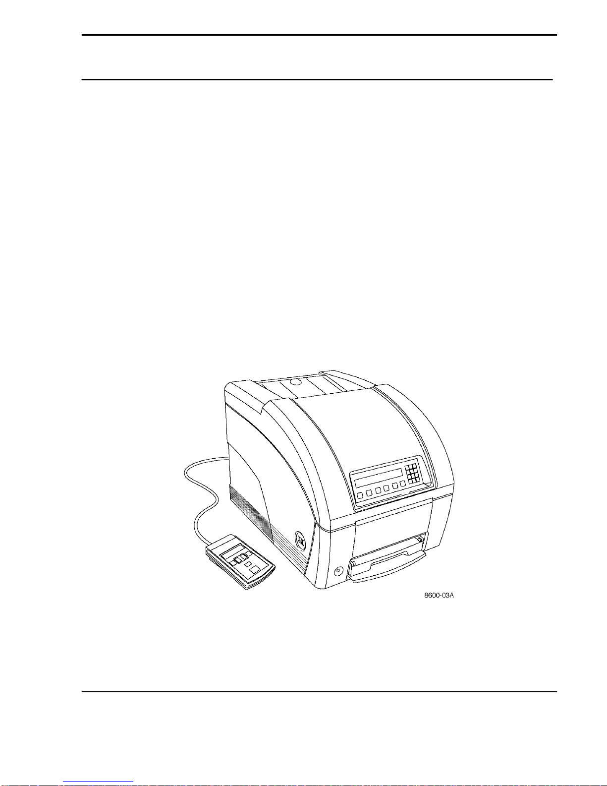
The Kodak DryView 8600 Laser Imaging System / for Mammography
The Kodak DryView 8600 Laser Imager / for Mammography is a continuous tone
laser imager with an integrated photothermographic film developer. The imager
produces high-quality monochrome images, using an optical laser scanning system,
a data control system that manages external data flow, and a film developer.
The imager uses 8 by 10-inch (20.3 by 25.4 cm) Kodak DryView Mammography
Laser Imaging Film. Each film package contains 100 sheets of film.
The imager produces the first print in approximately 185 seconds, and subsequent
prints at approximately 25 prints per hour. It can produce output from more than one
modality.
The imager acquires, formats and prints images under control of a host modality.
The operator uses a local panel on the imager for control of various local functions.
No machine maintenance is required of the operator.
Figure 1-1. Kodak DryView 8600 Laser Imager / for Mammography
1999 June Rev. A 8186546
1-1
Page 15

DryView 8600 User Guide
How the DryView 8600 Laser Imager Works
Each time it receives a print command, the imager prints an image using the
following sequence.
Note
The circled numbers in Figure 1-2 match the sequence steps. Dashed lines
show the film path.
1. Feed film – The feed area drives a sheet of film from the supply tray and feeds it
into the separation rollers.
2. Separate film – The separation rollers check for more than one sheet, then drive
a single sheet of film into the exposure module.
3. Expose film – A laser beam exposes the film. The film is then guided into the
film developer.
4. Develop film – The film develops as it passes over the heated developer drum.
5. Check image quality – The film is routed from the film developer, through the
densitometer, and out to the receive tray.
Figure 1-2. Print Sequence
1-2
8186546 1999 June Rev. A
Page 16

Section 1 – Introduction
Automatic Image Quality Control
The built-in densitometer is a key element in the Automatic Image Quality Control
(AIQC) process. It enables the imager to automatically adjust image processing
parameters to produce the best image. The imager adjusts these parameters each
time it prints a calibration film. A calibration film is printed when:
The DryView 8600 Laser Imager is powered on.
The film tray is inserted in the imager.
A calibration film is requested from the setup menu.
The imager has not been used for 8 hours, and any type of print is
requested.
The imager reactivates from Energy Saver mode.
Note
If the Energy Saver mode is activated, the DryView 8600 Laser Imager shuts
down its heaters and motors after 3 hours of inactivity. Any button pressed
reactivates the imager to automatically warm up to operating temperature.
Also, the imager reactivates if it is sent an image. A calibration film prints once
the imager reaches operating temperature.
Systems Connecting to the DryView 8600 Laser Imager
The DryView 8600 Laser Imager is used in full-field digital mammography (and in
other digital mammography applications) to reproduce digitized radiograph images
received from a digital radiography modality.
!
Warning
J1 (input/output) is intended for interconnection to equipment that complies
with the appropriate IEC 601-1/IEC 601-1-1 harmonized national standards
when interconnected.
Service and Installation
U.S. Connection: 120 volts Line to Neutral
Only factory-trained personnel are authorized to install and service the DryView
8600 Laser Imager. Circuit drawings are made available to the service technician.
1999 June Rev. A 8186546
1-3
Page 17

DryView 8600 User Guide
IMPORTANT NOTICE TO PURCHASER
Kodak warrants that the Kodak DryView 8600 Laser Imager will be free from defects
in parts, material and manufacture for the period of one (1) year from the date of
installation. For defects occurring during the warranty period and about which Kodak
has received notice during the warranty period, Kodak will provide Buyer with free
replacement parts and labor to replace warranty-covered items.
THIS WARRANTY IS MADE IN LIEU OF ALL OTHER PRODUCT WARRANTIES
EXPRESS OR IMPLIED, INCLUDING THE WARRANTIES OF MERCHANTABILITY
AND FITNESS, AND THOSE ARISING FROM A COURSE OF DEALING OR
USAGE OF TRADE.
The express warranty does not apply to the following: expendable parts; defects or
damage incurred in transportation to the end-user; defects or damage due to
neglect, misuse, operator error, improper installation or alteration of the DryView
8600 Laser Imager; or operation of the DryView 8600 Laser Imager out of
specification.
EXCEPT FOR THE EXCLUSIVE REMEDY STATED ABOVE, KODAK IS NOT
LIABLE FOR DIRECT DAMAGES. KODAK WILL NOT IN ANY EVENT BE LIABLE
FOR INDIRECT, INCIDENTAL OR CONSEQUENTIAL DAMAGES, REGARDLESS
OF THE LEGAL THEORY ASSERTED, INCLUDING NEGLIGENCE AND STRICT
LIABILITY.
1-4
8186546 1999 June Rev. A
Page 18

Section 2 – Controls and Indicators
Controls and Indicators
DryView 8600 Laser Imager Controls – Main
The imager uses the following controls. The numbered descriptions below
correspond to the numbered callouts in Figure 2-1.
1. Local Panel – Uses a two-line display with 40 characters per line to provide
status, setup, and test information. The panel contains six function buttons and a
numeric keypad. (See page 2-2 for details.)
2. Power Switch – Controls power to the imager.
3. Film Saver – Protects film from exposure when the film tray is temporarily
removed from the DryView 8600.
4. Remote Keypad –Displays control settings for the imager and allows you to
adjust these settings. (See page 2-3 for details.) This keypad is an option and
will not be used in all applications.
5. Manual Film Tray Release button – Allows the film tray to be removed without
the DryView 8600 Imager being powered on. Insert the film saver before using
this button or the film will be exposed.
Figure 2-1. DryView 8600 Laser Imager – Controls and Indicators
1999 June Rev. A 8186546
2-1
Page 19

DryView 8600 User Guide
Local Panel Controls and Indicators
The numbered descriptions below correspond to the numbered callouts in
Figure 2-2.
1. Display – Uses a two-line, alphanumeric display to provide status, setup, and
test information on the DryView 8600 Imager.
2. A and B Setup (buttons) – Select one of the two input modules for parameter
setup or changes. (B Setup is not currently used.)
3. Test (button) – Accesses the test menu.
4. Down and Up Arrows (buttons) – Scroll the display and move the display
cursor, when present.
5. Exit (button) – Allows user to exit any menu or local panel operation.
6. Enter (button) – Accepts entry. Executes commands or advances menu.
7. Numeric Keypad (buttons) – Allows user to enter numeric information.
8. Clear (button) – Clears (deletes) entries.
Figure 2-2. Local Panel
2-2
8186546 1999 June Rev. A
Page 20

Section 2 – Controls and Indicators
(Optional) Remote Keypad Controls and Indicators
The numbered descriptions below correspond to the numbered callouts in Figure
2-3.
1. Imager Ready (indicator) – When illuminated, indicates that the imager is
operational.
2. Check Imager (indicator) – Flashes to indicate a fault or out of film condition.
An associated error message is displayed on the local panel.
3. Memory Full (indicator) – When illuminated, indicates that there is insufficient
memory available to acquire another image. This condition is reported only to the
user whose image memory area is full. The condition should automatically
correct itself as the imager prints films and frees memory space.
2
1
9
10
8
3
4
5
6
7
1999 June Rev. A 8186546
Figure 2-3. Remote Keypad (Optional)
2-3
Page 21

DryView 8600 User Guide
4. Format Selected (indicator) – Displays the number of images (1, 2, 4, or 6) to
be printed on one sheet of film.
5. Select (button) – Selects the number of images to be printed on one sheet of
film. Sequences the Format Selected indicator through 1, 2, 4, and 6.
6. Print (button) – Prints the selected image(s). Pressing this button while the
PRESS PRINT for ADDITIONAL copy indicator is illuminated prints another
copy of the selected image(s).
7. Acquire (button) – Acquires images.
8. Press PRINT for ADDITIONAL copy (indicator) – When illuminated, tells you
that a print is developing and indicates that you can create an additional print if
you press the Print button while the indicator is illuminated.
9. Images Acquired (indicator) – Indicates the number of images acquired to be
printed on one sheet of film. The indicator only displays a number less than or
equal to the number displayed by the Format Selected indicator.
Note
If the imager is in the Autoprint mode, the print cycle begins automatically when
the number in the Images Acquired indicator equals the number in the Format
Selected indicator. When the number in the Images Acquired indicator is less
than the Format Selected indicator, you can press the Print button to start
printing.
10. Erase (button) – Deletes images in the reverse order from that in which they
were acquired. The last image acquired is the first deleted. As images are
deleted, the Images Acquired indicator decrements.
System Setup
The DryView 8600 Laser Imager provides setup menus that configure and adjust
the default settings (parameters) that control functions such as printing or image
density. Default settings are the values that are loaded when you switch on the
imager. (When your imager is installed, it is set up to work for your environment, so
you should rarely need to access and change the default function settings. They
should be changed only after consultation with the lead interpreting physician and a
Kodak representative.)
2-4
8186546 1999 June Rev. A
Page 22

Section 2 – Controls and Indicators
If the DryView 8600 Laser Imager is being used in a DICOM network, the Density,
Contrast, Print Contrast Samples, Sharp/Smooth, Gamma Table, Image Size, and
Detector Size parameters can be changed only at the modality or in the PACS Link
9410 Acquisition System. Changes in the PACS Link 9410 Acquisition System are to
be performed only by a Kodak service representative.
The general setup menus are accessed in the order shown below. Individual menu
descriptions are listed alphabetically in Table 2-1.
General Setup Menus
2.
1.
Format
See page 2-11
Mode
See page 2-12
1.
2.
3.
4.
5.
6.
7.
8.
Density *
Contrast *
Print Contrast
Samples *
Sharp/Smooth *
Polarity
Number of
Copies **
Autoprint **
Film Layout **
See page 2-10
See page 2-10
See page 2-13
See page 2-13
See page 2-12
See page 2-12
See page 2-9
See page 2-10
Keypad Format **9.
Audible Alerts **
10.
Exposure Index
11.
12.
13.
14.
15.
16.
Perform
Calibration
Date/Time
Gamma Table *
Image Size *
Detector Size *
See page 2-11
See page 2-9
See page 2-10
See page 2-12
See page 2-10
See page 2-11
See page 2-11
See page 2-10
* If the system is in a DICOM network, this parameter can be changed only at the
modality or in the PACS Link 9410 Acquisition System.
** Applicable to the optional Remote Keypad only.
1999 June Rev. A 8186546
2-5
Page 23

DryView 8600 User Guide
Menu Buttons
Use the following buttons to access and change parameter menus (see Figure 2-4):
1. A Setup (button) or B Setup (button) – Selects an input menu for setup. (B
Setup is not used in DICOM network installations.)
2. Down Arrow (button) – Scrolls to the next parameter menu. From the last
menu, scrolls to the first menu.
3. Up Arrow (button) – Scrolls to the previous parameter menu. From the first
menu, scrolls to the last menu.
4. Enter (button) – After you access a parameter menu, opens an editable display.
When you enter a new value for a parameter, pressing the Enter button enters
the new value for the parameter.
5. Exit (button) – Cancels changes entered in an editable display and restores the
original values or settings. Continued pressing allows quick exit of setup function.
6. Clear (button) – Clears an incorrect entry. If you enter values that are out of
range for a display, an audible signal sounds. To delete the incorrect value, press
the Clear button.
2-6
Figure 2-4. Menu Buttons
8186546 1999 June Rev. A
Page 24
Section 2 – Controls and Indicators
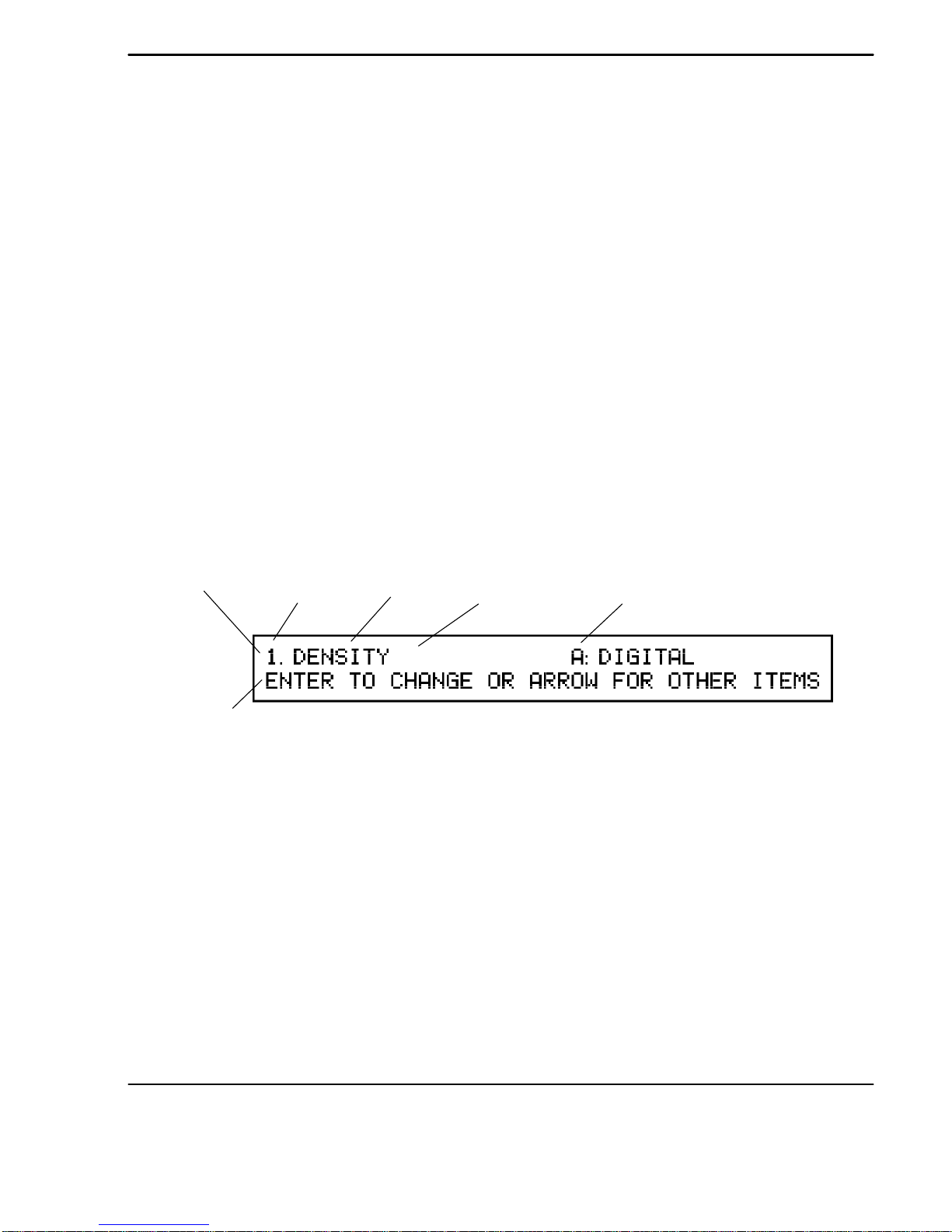
Menu Format
Parameter menus display information about the menu and the parameter.
The first menu for each parameter:
Tells you the menu number
Identifies the parameter
Lists the current value for the parameter
Identifies the current input module selected
Provides information about changing the parameter and continuing to the next
menu.
Subsequent menus tell you:
What to enter
The range of possible values for the parameter.
A sample parameter menu is shown in Figure 2-5, followed by the general procedure
used to change a parameter.
Information
Line
Action Line
Menu
Number
Parameter
Current
Value
6
Figure 2-5. Parameter Menu Display
Input
Module
1999 June Rev. A 8186546
2-7
Page 25

DryView 8600 User Guide
Menu Change Procedure
To change an individual parameter:
1. Select an input module by pressing either the A Setup or B Setup button.
(B Setup is not currently used.)
2. Access the parameter menu by using the Down or Up Arrow buttons to scroll
through the list.
Note
The location of each parameter menu is shown earlier in this section.
3. When the correct parameter is displayed, press Enter to access the parameter ’s
change menus.
You may find that you need to change information in a series of menus.
Each menu display contains an Information line (upper line) and an Action line
(lower line) instruction. (The Action line tells you how to change the parameter
and how to continue.)
4. Use the arrow buttons or the numeric keypad to change the value and then
continue to the next menu as instructed.
Note
If you enter a value that is out of range, the imager beeps. Clear the entry by
pressing the Clear button (see step 5) and re-entering the appropriate value.
5. When you have made changes to a menu, press one of the following buttons to
exit the menu:
To accept the changes and exit to the previous menu, press Enter.
To cancel the changes and exit to the previous menu with the original values
displayed, press Exit.
To delete a change and re-enter values for a parameter, press Clear. (Clear
does not exit from the current menu.)
Each parameter menu is listed in alphabetical order in Table 2-1.
2-8
8186546 1999 June Rev. A
Page 26

Parameter Menu Table
Section 2 – Controls and Indicators
Table 2-1. Parameter Menus
Parameter Menu
Description
Audible Alerts – Provides a one beep indication at the keypad for
each successful image acquisition.
– Provides three short beeps at the keypad to alert
the operator that image acquisition has failed. Retry
another image acquisition.
Selections:
ON = Alarm sounds
OFF = No alarm sounds
(This parameter applies only to the optional keypad.)
Autoprint Determines whether the imager prints images as
soon as the Images Acquired and Format Selected
indicators on the keypad display the same value.
Selections:
ON:
Prints when the Images Acquired and
Format Selected indicators display the same
value.
1999 June Rev. A 8186546
To print fewer images than indicated by the
Format Selected indicator, press Print as
soon as Images Acquired shows the number
of copies you want.
OFF:
Prints only when you press the Print button.
Note: To print contrast samples, Autoprint must be
set to OFF.
(This parameter applies only to the optional keypad.)
2-9
Page 27

DryView 8600 User Guide
Parameter Menu Description
Contrast Controls the amount of contrast in an image. Contrast
is the difference between the lighter and darker areas
of an image.
Range: 1 to 12
Use the contrast samples to choose the best value
and enter the number for that value.
(In a DICOM network, this parameter can be changed
only at the modality or in the PACS Link 9410
Acquisition System.)
Date/Time Changes date and time.
Press Enter to access each part of the date in turn or
the time.
A blinking cursor identifies the current value for each
part of the date or time.
Either use the numeric keypad to enter a new value,
or use the arrow buttons to change the value
displayed (such as the month or the year).
Density Controls the density of the image.
(In a DICOM network, this parameter can be changed
only at the modality or in the PACS Link 9410
Acquisition System.)
Detector Size Specifies the size of the pixels in the image to be
printed. This parameter is unused when Image Size
is Scale to Fit.
Note: This parameter is not user-adjustable.
Exposure Index This setting is for service only. Do not change.
Film Layout Allows you to select Format and Mode. (See those
entries in this table.)
(This parameter applies only to the optional keypad.)
2-10
8186546 1999 June Rev. A
Page 28

Section 2 – Controls and Indicators
Parameter Menu Description
Format Determines the number of images that print on a
single sheet of film.
Gamma Table Specifies which of two sets of gamma tables will be
used to control image brightness and density: (1)
transmittance or (2) linear optical density.
The DryView 8600 creates the two sets of 16 gamma
tables each time it self-calibrates. The gamma tables
are used by the DryView 8600 in conjunction with
the current contrast setting to provide grayscale
optimization.
Note: This parameter is not user adjustable. The
appropriate set of gamma tables is selected by the
Field Engineer with the user’s input at installation.
Image Size Defines the size of the printed image.
Scale to Fit: Image will be magnified or
reduced to fit the image area on the film,
unless the parameter is overridden by the
modality.
Note: This parameter is not user adjustable.
Keypad Format Determines the default number that displays on the
Format Selected indicator. The Format parameter
controls the number of images that print on a single
sheet of film.
Range: 1, 2, 4, and 6
If you change this value at the keypad, the new value
is not retained when you switch off the imager. When
the imager is switched on again, the default value
present before the manual change will be
re-displayed.
(This parameter applies only to the optional keypad.)
1999 June Rev. A 8186546
2-11
Page 29

DryView 8600 User Guide
Parameter Menu Description
Mode Allows setting printing mode to Landscape or Portrait.
Number of Copies Changes the number of copies printed.
Range: 1 to 99
(This parameter applies only to the optional keypad.)
Perform Calibration Prints a calibration step wedge using current settings,
then calibrates the densitometer.
Press Enter to start the calibration.
If a problem occurs during calibration, the imager
displays an error message. Refer to Troubleshooting,
Table 5-1, for information on how to deal with the
problem.
Polarity Determines whether image is printed as a positive or
negative.
Selections:
POSITIVE
If the acquired image is positive, prints a
positive image and vice versa.
NEGATIVE
Reverses the acquired print (a positive
acquired image is printed as a negative and
vice versa).
2-12
8186546 1999 June Rev. A
Page 30

Section 2 – Controls and Indicators
Parameter Menu Description
Print Contrast Samples Prints contrast samples (uses the last acquired image
for the sample and current density).
To print samples, press Enter.
During printing, print progress is indicated. If no fault
appears during printing, returns to the Print Contrast
Samples menu. To stop printing, press Exit.
(In a DICOM network, this parameter can be changed
only at the modality or in the PACS Link 9410
Acquisition System.)
Sharp/Smooth Determines the sharpness or smoothness of the
printed image. Smooths out the jagged edges of the
pixels in an image as specified.
Selections:
Range: 1 to 6 or Auto
1 = Sharpest image
6 = Smoothest image
Auto = The imager determines the
best setting for the size of the image.
Current setting is marked by an asterisk (*).
(In a DICOM network, this parameter can be changed
only at the modality or in the PACS Link 9410
Acquisition System.)
1999 June Rev. A 8186546
2-13
Page 31

DryView 8600 User Guide
BLANK PAGE
2-14
8186546 1999 June Rev. A
Page 32

Section 3 – Operation
Operation
System Power Up
Set the imager power switch to ON. The following sequence occurs:
1. The imager performs a series of self-diagnostic tests.
2. If the power-on self-test is successful, the machine warms up for about 25
minutes.
3. After warmup, the machine calibrates the densitometer lamp.
4. After calibrating the densitometer lamp, the machine prints a calibration step
wedge.
Note
The system displays a message for each stage of system power up.
Figure 3-1. Power Switch, Local Panel and Optional Remote Keypad
2000 March Rev. B 8186546
3-1
Page 33

DryView 8600 User Guide
Producing a Print from a Host Modality
After warmup and calibration, the DryView 8600 Laser Imager is ready to print.
Print commands are issued and controlled from the digital host modality.
Producing a Print Using the Optional Keypad
Note
The following procedure does not apply if the DryView 8600 Laser Imager is
being used in a DICOM network.
1. Power on the imager.
2. Wait for the green Imager Ready (1) indicator to illuminate.
3. Press Select (2) repeatedly until the desired number appears on the Format
Selected indicator (3).
Note
You can select a format only if no images are acquired or all acquired images
are printed.
4. To start image acquisition, press Acquire (4) or use the optional foot activated
switch (Foot Switch).
If acquisition is successful, the Images Acquired (5) indicator increments
and one short beep is sounded.
If acquisition is unsuccessful:
– The audible alarm of three short beeps sounds (if set to ON).
– The Images Acquired (5) indicator does not increment.
– The Check Imager (6) indicator lights
– An associated message appears on the local panel.
Note
The failure indication is visible only at the keypad where acquisition was
unsuccessful. After an unsuccessful attempt, you should try to acquire an
image again. If the acquire is successful, the Check Imager (6) indicator turns
off and the Images Acquired (5) indicator increments and one short beep is
sounded.
5. Repeat step 4 until all images are acquired.
3-2
8186546 2000 March Rev.B
Page 34

Section 3 – Operation
Note
To delete images in reverse order, starting with the most recently acquired
image, press the Erase button (7). The Images Acquired (5) indicator
decrements as the images are deleted.
6
1
5
10
3
2
7
9
8
4
2000 March Rev. B 8186546
Figure 3-2. Optional Keypad
3-3
Page 35

DryView 8600 User Guide
6. To print the images acquired at any time, press the Print button (8). Any blank
image locations are printed at background density.
Note
If Autoprint is ON, images also print when the number in the Images Acquired
indicator (5) equals the number in the Format Selected indicator (3).
Note
The number of images printed is determined by the Number of Copies to Print
setting.
7. To print additional copies, press Print (8) whenever the Press PRINT for
ADDITIONAL copy indicator (9) is illuminated. Each button press prints one
additional copy.
Note
If the Memory Full indicator (10) lights, wait until the indicator goes out before
pressing Acquire again.
Note
If the Check Imager indicator (6) lights with no associated beep when the
acquisitions are successful, there is a condition such as out of film, or film jam
at the imager, which is not currently affecting acquisitions.
Note
If a film jam occurs during printing, the Check Imager indicator (6) lights, and
the local panel displays an associated message. Clear the jam (see page 5-7,
Troubleshooting, for instructions). When the jam is cleared, the machine
restarts the print sequence.
3-4
8186546 2000 March Rev.B
Page 36

Section 3 – Operation
6
1
5
10
3
2
7
9
8
4
2000 March Rev. B 8186546
Figure 3-3. Optional Keypad
3-5
Page 37

DryView 8600 User Guide
Requesting Contrast Samples and Changing the Contrast Setting
The user can adjust both density and contrast for printed images. The density
setting is incremental, which means that the maximum density of a printed image
increases as the number of the density setting is increased.
The contrast setting is not incremental. The user must select a desired setting from
contrast examples of a printed image. You must select the procedure to print
contrast samples for the modality that you are using.
Note
If the DryView 8600 is being used in a DICOM network, the following
procedures to request contrast samples and adjust contrast do not apply.
Digital Modality with Host Control
A modality with host control capabilities usually defines and sends the density and
contrast information to the imager when the image data is sent, overriding the values
set at the imager’s local panel. If the modality does not send density and contrast
information, the user can define the settings at the local panel.
1. At the host, acquire an image, but do not send a print command.
2. On the DryView 8600 local panel, press
A
Setup
or
B
(see Figure 3-4) to select
Setup
the menu that represents the host-controlled modality from which you will print
contrast samples.
3. Press
to go to item 3, Print Contrast Samples, and then press
Enter
.
(The DryView 8600 automatically prints 12 copies of the previously acquired
image at different contrasts.)
4. Select the image that you prefer, and note the image number associated with it.
5. On the local panel, press
to go to item 2, Contrast.
6. Following the instructions on the display, change the contrast setting to the
number previously selected from the contrast samples. Then press
7. After setting the contrast, press
to return the DryView 8600 to service.
Exit
Enter
.
3-6
8186546 2000 March Rev.B
Page 38

Section 3 – Operation
Figure 3-4. Changing the Contrast Setting
Digital Modality with Remote Keypad
1. On the modality, select and display the image you want to use for printing
contrast samples.
2. On the DryView 8600 remote keypad, select a format other than 1. (For
example, use 2, 4, or 6.)
3. Press Acquire on the keypad.
4. On the local panel, press
A
Setup
or
B
to select the menu that represents the
Setup
host-controlled modality from which you will print contrast samples.
5. On the local panel, press
then press
. (The DryView 8600 automatically prints 12 copies of the
Enter
to go to item 3, Print Contrast Samples, and
previously acquired image at different contrasts.)
6. Select the image that you prefer, and note the image number associated with it.
7. On the local panel, press
to go to item 2, Contrast.
8. Following the instructions on the display, change the contrast setting to the
number previously selected from the contrast samples, then press
Enter
.
9. After setting the contrast, press
2000 March Rev. B 8186546
to return the DryView 8600 to service.
Exit
3-7
Page 39

DryView 8600 User Guide
Loading/Unloading the Film Tray
Note
Leave the DryView 8600 Laser Imager on while loading or unloading the film
tray. If you remove power from the imager while the system is in use, any
previously acquired images stored in memory will be lost.
1. When 100 sheets of Kodak DryView Mammography Laser Imaging Film have
been used, the tray unlocks automatically, and instructions for tray removal are
displayed on the local panel. (See Figure 3-5.)
2. Swing open the handle of the film tray.
3. Important: Remove the old film insert and any unused “liner” sheet of film from
the tray and dispose of them per local disposal regulations. (The liner sheet
contains a trace of silver.)
Note
Before loading a new package of film, clean the inside surface of the film tray,
including the ramp and top edge of the tray. Use an alcohol soaked pad such
as TexPad TX801.
4. Press the film package down in the tray as follows: Press the film package to the
left, against the soft guide, with the black plastic bag tail lapping through the
handle, and the label up. Press down firmly using both hands so the film
package sits flat against the bottom of the tray.
5. Swing the handle of the film tray back in place.
6. Remove the tear strip from the black plastic bag.
7. Slide the tray back into the imager slot.
8. To remove the black plastic bag so the imager can access the Kodak DryView
Mammography Laser Imaging Film, pull the black plastic bag tail firmly and
smoothly. The entire film bag should slide out.
9. Dispose of the black plastic bag.
10. To continue processing images, press
on the local panel.
Enter
3-8
8186546 2000 March Rev.B
Page 40

Section 3 – Operation
2000 March Rev. B 8186546
Figure 3-5. Loading/Unloading Film
3-9
Page 41

DryView 8600 User Guide
BLANK PAGE
3-10
8186546 2000 March Rev.B
Page 42

Section 4 – Quality Control Procedures
Section 4 – Quality Control Procedures
Compliance Guidance – Quality Control for Laser Imagers used in
Digital Mammography Systems
These Quality Control Procedures are intended to provide guidance for
mammography facilities and their personnel. They represent the equipment
manufacturer’s views on the appropriate procedures for conducting Quality Control
tests for digital mammography and observing the Mammography Quality Standards
Act (MQSA). The following procedures represent acceptable ways of doing the tests,
but unlike regulations, they are not binding. Alternate procedures may be used if
they satisfy the requirements of the applicable statute, regulations, or both. It is the
responsibility of the mammography facility to read, understand, and follow the
regulations.
Under its own authority, a state may impose requirements more stringent than those
imposed in the FDA Mammography Quality Standards Act. A facility should check
with state or local authorities regarding their requirements.
Automatic Image Quality Control and the QC Process
The Kodak DryView 8600 Laser Imager / for Mammography has a built-in Automatic
Image Quality Control (AIQC) system that automatically compensates for film lot
variations, ensuring consistent print densities. The MQSA requires that the
mammography facility establish a quality control (QC) process that verifies the
effectiveness of the AIQC system. Kodak’s recommendations below are based on
the MQSA and the QC process described in the Radiologic Technologist’s
Section of
the Mammography Quality Control Manual, W 1999, published by the American
College of Radiology. This QC process has been adapted to apply to the special
features of Kodak DryView Mammography Laser Imaging Film and the
characteristics of the Kodak DryView 8600 Laser Imager. The procedures outlined
below assume that the user has been trained in operation of the Kodak DryView
8600 Laser Imager.
Running a QC Baseline Test
Per the MQSA, a baseline test must be run when the 8600 is first installed, and must
be repeated every time a box of film with a different emulsion number is used. This
test sets up a baseline set of film parameter values that shall be used as a standard
for comparison in daily quality control tests. Kodak recommends the procedure
described below as a means of complying with this regulation.
2000 March Rev. B 8186546
4-1
Page 43

DryView 8600 User Guide
Procedure for the Installing Field Engineer – The installing field engineer verifies
that the 8600 meets its performance specifications, runs the baseline test described
below, and prints a clinical image of the site’s choice. The site’s responsible
healthcare professional is asked to approve that the 8600 produces an acceptable
clinical image. If the image is not acceptable, the field engineer repeats his
procedures until the settings for the baseline print produce acceptable clinical
images.
Procedure for the QC Technologist – After an acceptable installation, the user
facility’s technologist must repeat the baseline test whenever a change occurs in
emulsion lots.
Baseline Test
1. Apply power to the 8600 and allow it to warm to READY, as indicated on the
local panel. The 8600 will print a film calibration sheet, to put its Automatic Image
Quality Control (AIQC) system in control.
2. Print a QC Step Wedge test film. ( Refer to page 5-15 in this User Guide for the
procedure. See Figure 4-1 on the next page for a sample step wedge,)
3. Repeat printing QC Step Wedge films until you have accumulated five test films.
4. Using a densitometer, read and record the density of each step (1 through 21) on
each of the five test films. (For consistency from film to film, always read density
at the center of each wedge.)
Note
You can choose to use a clear area on the test films instead of the actual step
1 to take the “step 1” density readings.
5. Determine and record the average of the five densities read for each step.
6. Select from the average values calculated from the 21 steps to determine the
film parameter values as follows:
a. Determine which step has a density closest to 2.20. Then determine which
step has a density closest to but not less than 0.45. Designate the difference
between these densities as Density Difference (DD).
b. Determine which step has an average density closest to but not less than
1.20. Designate this step as Medium Density (MD).
c. Designate the average for Step 1 (or the clear area on the film) as Base Plus
Fog.
4-2
8186546 2000 March Rev. B
Page 44

Section 4 – Quality Control Procedures
d. Record the numeric values of DD, MD and Base Plus Fog on the center lines
of the Laser imager QC Chart. (See Figure 4-2.) Record also the step
numbers involved.
2000 March Rev. B 8186546
Figure 4-1. QC Step Wedge
4-3
Page 45

DryView 8600 User Guide
Density
Difference
HD Step #___
–HD Step #___
Medium
Density
Step #___
Base
Plus Fog
Figure 4-2. Quality Control Chart
4-4
8186546 2000 March Rev. B
Page 46

Section 4 – Quality Control Procedures
Running a Daily QC Test
The MQSA requires that a sensitometric test be run daily and that clinical images be
made only when the control chart is within the control ranges. Kodak recommends
the following laser imager test. Perform this test daily before clinical mammograms
are run, to ensure quality output. Plot the values obtained from the test on the Laser
Imager QC Chart for comparison with the film parameter values established in the
baseline test.
1. Apply power to the 8600 and allow it to warm to READY, as indicated on the
local panel. (The 8600 will print a film calibration sheet, indicating that its
Automatic Image Quality Control system is functioning.)
2. Print a QC Step Wedge film per the procedure on page 5-15 of this User Guide.
3. Use a densitometer to read the designated steps on the test film. Read at the
center of each step. If a clear area on the film was used instead of step 1 in the
baseline tests (see page 4-2), use a clear area in this QC test.
4. Record the date on the control chart. Then plot the DD, MD, and Base Plus Fog
values in the appropriate column on the chart.
5. Determine if any of the values exceeds the control limits for the parameter.
Note
The numbers above and below the center lines on the chart indicate the
control limits. For example, for DD or MD, 0.10 above or below the center line is
approaching the limit, but is acceptable. However, 0.15 above or below the line
is not acceptable.
6. If the values did not exceed a control limit, examine the chart and see if there is
a trend which suggests possible future problems. (This could be, for example,
three or more data points for DD, MD or Base Plus Fog in succession moving
upward or downward.) If the data points have not exceeded the limits, clinical
mammograms can continue to be run.
7. If any value exceeds a control limit, DO NOT run clinical mammograms until the
problem is corrected. Proceed as follows:
a. Circle the out of control point(s) on the chart.
b. Correct the problem. (The fault could be in the film, imager or densitometer,
or in the performance of the QC procedure.)
c. Note the cause of the problem in the “Remarks” section of the control chart.
d. Repeat the step wedge test and graph the parameters on the control chart.
2000 March Rev. B 8186546
4-5
Page 47

DryView 8600 User Guide
BLANK PAGE
4-6
8186546 2000 March Rev. B
Page 48

Section 5 – T roubleshooting
Section 5 – Troubleshooting
Local Panel and Remote Keypad Message Types
The local panel displays two types of messages:
Status Messages – Provide information and require no operator action.
Error Messages – Indicate an error condition inside the imager. Some
messages tell you what action to take to fix the error, but in some cases a
service call is needed to deal with a problem. If the error message does not clear
after you perform the specified action, call for service.
Table 5-1 lists all messages that can appear on the two lines of the local panel
display:
The Information Line (line 1) of each display contains the error title and (in most
cases) a two-digit error code.
The Action Line (line 2) contains additional information/procedures about the
error condition.
Note
The keypad indicates that an error has occurred by flashing the Check Imager
indicator, which refers the operator to the imager’s local panel for more detailed
error information.
Local Panel Messages
If the Operator Action specified in Table 5-1 does not correct the machine problem,
call for service (see page 5-20).
Table 5-1. Operator Related Local Panel Messages
Message
ASIC LINE BUFFER F AIL (48)
CALL SERVICE – PRESS ENTER TO
CONTINUE
ASIC SELF TEST F AIL (60)
CALL SERVICE – PRESS ENTER TO
CONTINUE
Power the imager off, wait 10-20
seconds, then power back on. If
message reappears, call for service.
Power the imager off, wait 10-20
seconds, then power back on. If
message reappears, call for service.
Operator Action
2000 March Rev. B 8186546
5-1
Page 49

DryView 8600 User Guide
Message Operator Action
A TO D CONVERTER FAILURE (88)
POWER IMAGER OFF, THEN BACK ON
CALIBRATION FAILED (69)
PRESS ENTER TO LOAD DEFAULT GAMMA
TABLES
CALIBRATION FAIL: Dmin HI, Dmax XXX.X (70)
PRESS ENTER TO BUILD GAMMA TABLES
DEVELOPER OVER TEMPERATURE (17)
POWER IMAGER OFF, THEN BACK ON
DEVELOPER UNDER TEMPERATURE (19)
POWER IMAGER OFF, THEN BACK ON
Power the imager off, wait 10-20
seconds, then power back on. If
message reappears, call for service.
Press Enter. Then stand by while
imager automatically loads default
tables. Make sure to check image
quality.
Press Enter. Then stand by while
imager automatically builds gamma
tables. If image quality is unacceptable,
use new film.
Unable to control temperature. Power
imager off, wait 10-20 seconds, then
power back on. If message reappears,
call for service.
Unable to control temperature. Power
imager off, wait 10-20 seconds, then
power back on. If message reappears,
call for service.
DOUBLE FILM FEED – REMOVE MISFEED (24)
INSERT FILM SAVER TO REMOVE FILM TRAY
Insert the film saver and remove the film
tray. Discard any sheets of film that are
jammed in the machine. If problem
persists, call for service.
DYNAMIC RAM FAILURE (72)
CALL SER VICE – PRESS ENTER TO CONTINUE
Power imager off, wait 10-20 seconds,
then power back on. If message
reappears, call for service.
FILM TRAPPED INSIDE EXPOSURE AREA (23)
CALL SERVICE – IMAGER IS INOPERABLE
Insert the film saver. Raise the cover
and remove the film from the exposure
area. Close the cover and remove the
film saver. Press Enter to continue. If
film can’t be removed, call for service.
FILM TRAY EMPTY – INSERT FILM (29) Imager is out of film. Remove film tray
and load a new film package.
FILM TRAY UNLOCKED (11).
INSERT FILM TRAY FULLY TO CLEAR ERROR
Remove and reinsert film tray into
Imager.
5-2
8186546 2000 March Rev. B
Page 50

Section 5 – T roubleshooting
Message Operator Action
FLASH EPROM FAILURE (75)
CALL SERVICE – PRESS ENTER TO
CONTINUE
GALVANOMETER FAILURE (45)
CALL SERVICE – PRESS ENTER TO
CONTINUE
IMAGE MEMORY FOR INPUT A (B) IS FULL
(80) PRESS ENTER TO CONTINUE
IMAGER OFF-LINE
PRESS ENTER TO PLACE IMAGER IN
SERVICE
IMAGER OPEN (16)
CLOSE COVER
INPUT A (B) ACQUISITION TIMEOUT (66) Retry image acquire. Check wire
Power imager off, wait 10-20 seconds,
then power back on. If message
reappears, call for service.
Power imager off, wait 10-20 seconds,
then power back on. If message
reappears, call for service.
Press Enter to continue. As films are
printed, memory will become available.
Press Enter to place imager in service.
Be sure the top cover is closed and
latched.
connections from the modality to the
imager. If problem persists, call for
service.
INPUT A (B) DMA F AILURE (74)
CALL SERVICE – PRESS ENTER TO
CONTINUE
Power imager off, wait 10-20 seconds,
then power back on. If message
reappears, call for service.
INPUT A (B) FIFO NOT EMPTY FAILURE (67) Reacquire the image to be printed.
INPUT A (B) HEADER FAILURE (64) Try acquiring an image again. If problem
persists, call for service.
INPUT A (B) IDENTIFY ERROR (63)
CALL SERVICE – PRESS ENTER TO
CONTINUE
INPUT A (B) IMAGE SIZES NOT IDENTICAL
(35) PRESS ENTER TO CONTINUE
INPUT A (B) IMAGE TOO LARGE TO PRINT
(37)
PRESS ENTER TO CONTINUE
INPUT A (B) OVERFLOW FAILURE (65) Try acquiring an image again. If problem
Power imager off, wait 10-20 seconds,
then power back on. If message
reappears, call for service.
Verify the image is the same size as the
previously captured image.
Maximum image size is 6.1 megabytes.
Retry with a smaller image.
persists, call for service.
2000 March Rev. B 8186546
5-3
Page 51

DryView 8600 User Guide
Message Operator Action
INPUT A (B) PROGRAM MEMORY FULL
PRESS ENTER TO CONTINUE
INPUT A (B) SYNC FAILURE (39) Power imager off, wait 10-20 seconds,
Press Enter to continue.
then power back on. If message
reappears, call for service.
INPUT A (B) UNDERFLOW FAILURE (62) Try acquiring an image again. If problem
persists, call for service.
INSERT FILM TRAY (12) Insert the film tray.
INSUFFICIENT MEMORY FOR IMAGE FILE A
(B) (81) PRESS ENTER TO CONTINUE
INSUFFICIENT MEMORY FOR PRINTSET A (B)
(82) PRESS ENTER TO CONTINUE
INVALID DATA RECEIVED FROM INPUT A (B)
(53) - PRESS ENTER TO CONTINUE
LAMP FAILED TO REACH TEMPERATURE (71)
PRESS ENTER TO LOAD DEFAULT GAMMA
TABLES
Press Enter to continue. As films are
printed, memory will become available.
Press Enter to continue. As films are
printed, memory will become available.
Call for service.
Call for service.
LASER BOARD FAILURE (46)
CALL SERVICE – PRESS ENTER TO
CONTINUE
LOADING DEFAULT GAMMA TABLES Automatic operation. Verify image
Power imager off, wait 10-20 seconds,
then power back on. If message
reappears, call for service.
quality.
LOCAL PANEL BUFFER OVERFLOW (85)
CALL SERVICE – PRESS ENTER TO
CONTINUE
LOCAL PANEL RAM FAILURE (73)
CALL SERVICE – PRESS ENTER TO
CONTINUE.
MAXIMUM DENSITY LESS THAN 3.5 No action required.
NO IMAGE ACQUIRED ON INPUT A (B) (68)
PRESS ENTER TO CONTINUE
NON-VOLATILE CLOCK RAM FAILURE (96)
CALL SERVICE – PRESS ENTER TO
CONTINUE
Power imager off, wait 10-20 seconds,
then power back on. If message
reappears, call for service.
Power imager off, wait 10-20 seconds,
then power back on. If message
reappears, call for service.
Reacquire an image.
Power imager off, wait 10-20 seconds,
then power back on. If message
reappears, call for service.
5-4
8186546 2000 March Rev. B
Page 52

Section 5 – T roubleshooting
Message Operator Action
NON-VOLATILE RAM FAILURE (97)
CALL SERVICE – PRESS ENTER TO
CONTINUE
NO RESPONSE FROM KEYPAD A (B) (78)
PRESS ENTER TO CONTINUE
Power imager off, wait 10-20 seconds,
then power back on. If message
reappears, call for service.
Power imager off, wait 10-20 seconds,
then power back on. If message
reappears, call for service.
NO RESPONSE FROM INPUT A (B) Power imager off, wait 10-20 seconds,
then power back on. If message
reappears, call for service.
PERFORMING CALIBRATION None.
PERFORMING SELF-TEST None.
POWER DISTRIBUTION FAILURE (49)
TURN OFF IMAGER – CALL SERVICE
Power imager off, wait 10-20 seconds,
then power back on. If message
reappears, call for service.
PRINT JOB LIST FULL (86)
PRESS ENTER TO CONTINUE
REGULATING TEMPERATURE Imager adjusting temperature. If not
Wait until some films have printed
before sending more images to print.
completed in 45 minutes, call service.
REMOVE FILM FROM EXIT AREA (28)
INSERT FILM SAVER TO REMOVE FILM TRAY
Insert the film saver. Raise the cover
and remove film from the exit area.
Close cover and remove the film saver.
Press Enter to continue.
REMOVE FILM SAVER (31) Remove the film saver from the tray.
REMOVE FILM TRAY (40) Insert film saver and remove film tray.
REMOVE, LOAD, AND INSERT FILM TRAY (12) Remove the film tray, load film, and
re-install the film tray.
REMOVE, LOAD, AND INSERT FILM TRAY (30)
PRESS ENTER WHEN READY TO REMOVE
TRAY
Press Enter. Remove the film tray, load
film, and re-install the tray.
2000 March Rev. B 8186546
5-5
Page 53

DryView 8600 User Guide
Message Operator Action
REMOVE MISFEED FROM DEVELOPER AREA
(27)
INSERT FILM SAVER TO REMOVE FILM TRAY
REMOVE MISFEED FROM EXPOSURE AREA
(22) INSERT FILM SAVER TO REMOVE FILM
TRAY
REMOVE MISFEED FROM FILM TRAY (20)
INSERT FILM SAVER TO REMOVE FILM TRAY
REPEATED ERROR DURING EXPOSURE (50)
PRESS ENTER TO PRINT ALL QUEUED
IMAGES
TIMEOUT WAITING FOR FILM TRAY REMOVAL
– PRESS ENTER WHEN READY TO REMOVE
TRAY
Film stopped in the developer area.
Check for blockage of film path from
developer. Insert film saver. Raise cover
and open the developer cover. Remove
the film sheet and close the developer
cover. Close the cover and remove the
film saver. Press Enter to continue.
Insert film saver. Raise cover and
remove film from exposure area. Close
cover and remove film saver. Press
Enter to continue.
Insert film saver. Remove film tray.
Remove misfed film sheet.
Press Enter to print all queued images.
Call for service if error persists.
Press Enter. Then remove the film tray
when the release latch is activated.
UNABLE TO FEED FILM (33)
PRESS ENTER TO TRY AGAIN
Message is displayed after third attempt
to feed film. Insert the film saver and
remove the film carrier from the imager.
Gently shake the film carrier. Remove
any film stuck in film tray cavity of
imager and reinsert tray. Press Enter to
try again.
UNABLE TO UNLOCK FILM TRAY (34)
REMOVE FILM TRAY MANUALLY TO
CONTINUE
UNASSIGNED ERROR CONDITION Call for service.
VERY FEW STEPS IN TOE OF DLOG E CURVE
VERIFY IMAGE QUALITY
WAIT FOR SHEET TO EXIT BEFORE
REMOVING TRAY FROM IMAGER
WARMING UP None.
Manually depress the film carrier
release button on the imager and
remove film tray manually.
Examine the quality of the calibration
print. You may have to try new film.
Wait for sheet to exit before removing
tray from imager.
5-6
8186546 2000 March Rev. B
Page 54

Section 5 – Troubleshooting
Clearing Film Jams – General
The film jam areas referred to in local display error messages are shown in
Figure 5-1.
A is the film tray area, where film misfeeds can possibly occur.
B and C identify the rollers on either side of the exposure area.
D and E identify the developer and film exit areas.
E
C
D
Film Tray
B
A
8300–1
83L
Figure 5-1. Possible Film Jam Locations
The following pages provide procedures for clearing film jams from all the areas
identified above. Before performing any of the procedues you must install the film
saver on the film tray, and remove the film tray from the machine.
Note
Shutting off power to clear a film jam is not required. Shutting off the power
deletes all currently acquired (but unprinted) images and may clear some
error messages. If you do this, you will have to resend the unprinted images to
the imager.
2000 March Rev. B 8186546
5-7
Page 55

DryView 8600 User Guide
Inserting the Film Saver and Removing the Film Tray
1. Insert the film saver and remove the film tray as shown in Figure 5-2.
2. If the film tray does not pull out, use a pen or pencil to push the tray release
button located on the left side of the film tray. See Figure 5-3.
Figure 5-2. Inserting the Film Saver and Removing the Film Tray
Film Tray
Release Button
8300-135A
Figure 5-3. Releasing the Film Tray
5-8
8186546 2000 March Rev. B
Page 56

Section 5 – T roubleshooting
Clearing Jams from the Film Tray Area
1. Check to see if a jam has occurred in the film tray, or film is partially protruding
from the tray.
2. Check inside the tray opening of the machine for jammed film.
3. If you cannot locate the jam, raise the top cover after pushing in the button on
the right side of the machine (see Figure 5-4). Then proceed to the next
paragraph.
2000 March Rev. B 8186546
Figure 5-4. Raising the Top Cover
5-9
Page 57

DryView 8600 User Guide
Clearing Jams from the Exposure Area
With the top cover open, allow time for the developer to cool. Visually check for a
film jam in the interior of the machine.
1. Lift the wire guide for access to film in the bottom of the machine. See Figure
5-5.
2. Place the wire guide in the upward position as shown in Figure 5-5.
3. Remove any film jams.
4. Return the wire guide to its original position. Make sure it snaps into place.
1
3
2
4
Figure 5-5. Clearing Film Jams in the Exposure Area
5-10
8186546 2000 March Rev. B
Page 58

Section 5 – T roubleshooting
Clearing Jams from the Developer and Exit Areas
Safety Precautions
Take care working around the developer area. The developer drum is hot during
normal system operation. When the machine top cover is raised, power is
disconnected from the drum and it begins to cool down. However, up to an hour may
elapse before the drum is cool.
!
Caution
Do not touch the developer drum.
8300-128A
2000 March Rev. B 8186546
5-11
Page 59

DryView 8600 User Guide
Clearing the Developer or Exit Jam
1. Open the top cover and unlatch the developer assembly cover (see Figure 5-6).
2. Open the developer assembly cover and allow time for the developer to cool.
3. Pull to remove any jammed film. (Caution: The film may still be hot.) To aid in
removing the film, you may rotate the drum by turning the gear on the left side of
the drum.
4. Close and latch the cover.
1
8300-32A
3
2
8300-33A
4
Figure 5-6. Clearing Film Jams from the Developer and Exit Areas
Note
Check to see that all jams reported by error messages have been corrected. If
additional error messages have occurred, they may recur after the power-up
self test. If they do, refer to Table 5-1 for instructions.
5-12
8300-34A
8300-35A
8186546 2000 March Rev. B
Page 60

Section 5 – T roubleshooting
System Tests
Use the test menus to test DryView 8600 Laser Imager operation.
Note
While running system tests, you cannot acquire and print images.
You can run the following tests on the imager:
1. QC Step Wedge – Prints a QC step wedge for use in the daily quality control
process (see Section 4).
2. Print SMPTE Pattern – Prints four stored test pattern images on one film.
3. Keypad Test – Tests keypad and individual key functions.
4. Display Software Versions – Displays versions for software programs that run
the imager.
5. Display System Configuration – Displays current system configuration values
such as image memory, contrast and density parameters for each input (user).
Test Menus
QC Step Wedge
See page 5-15
Print SMPTE
Pattern 4:1
See page 5-15
Keypad Test
See page 5-16
Display Software
Versions
See page 5-17
Display System
Configuration
See page 5-18
2000 March Rev. B 8186546
5-13
Page 61

DryView 8600 User Guide
Menu Buttons
Use the following buttons to access, start, and exit test menus:
1. Test Button – Accesses test menus.
2. Down Arrow Button – Scrolls to the next test. From the last test, scrolls to the
first test.
3. Up Arrow Button – Scrolls to the previous test. From the first test, scrolls to the
last test.
4. Enter Button – After you access a test menu, allows required conditions to be
set or starts a test.
5. Exit Button – Cancels a test or a parameter change.
5-14
Figure 5-7. Menu Buttons
8186546 2000 March Rev. B
Page 62

Print QC Step Wedge
To print a QC step wedge:
Section 5 – T roubleshooting
1. Access the QC Step Wedge menu by pressing
2. Initiate the test print by pressing
Enter
.
Test
.
If the step wedge prints successfully, the Print QC Step Wedge menu is
again displayed.
If a fault occurs, an error message is displayed.
3. To cancel the test, press
. The system displays a “PRINT CANCELLED BY
Exit
OPERATOR” message.
4. To return to “System Ready,” press
Exit
.
Print SMPTE Pattern
To run a Print SMPTE Pattern test:
1. From the QC Step Wedge menu, press
to access the Print SMPTE Pattern
display.
2. To print the SMPTE pattern, press
Enter
.
Follow instructions on the local panel to set up conditions for the test.
If the print completes successfully, the Print SMPTE Pattern menu is
displayed.
If a fault occurs, an error message is displayed.
3. To cancel the print, press
. The system displays a TEST CANCELLED BY
Exit
OPERATOR message.
4. To return to the first Print SMPTE Pattern menu, press
Exit
.
2000 March Rev. B 8186546
5-15
Page 63

DryView 8600 User Guide
Keypad Test
Before you can run a keypad test, a remote keypad must be attached to the imager.
To run a keypad test for one of the input modules :
1. From the Print SMPTE Pattern display, press
to access the Keypad Test
menu.
2. To start the Keypad Test, press
Enter
.
During the first part of the keypad test, the menu shows test progress.
3. When the first part of the test is complete, the menu prompts you to press any
key. To test individual key function, press each key in turn.
Each time you press a key, the menu should identify the pressed key.
Example: If you press
4. To cancel the test, press
, the menu should show that you pressed it.
Erase
. The system displays a “TEST CANCELLED BY
Exit
OPERATOR” message.
5. To return to the first Keypad Test menu, press
Exit
.
6. To perform the keypad test on the other input module, press
steps 2 through 5.
5-16
8186546 2000 March Rev. B
and repeat
Page 64

Section 5 – T roubleshooting
Display Software Versions
The imager contains the following types of software.
Imager Firmware
VRTX32
Contrast Tables
Convolution Kernel
If you need to check the version of one of these software programs, access the
software versions as follows:
1. From the Keypad Test display, press
to access the Display Software
Versions menu. Use this menu to access the software versions.
2. To see the current Imager Firmware version, press
Enter
IMAGER FIRMWARE 2.0
3. To access the VRTX32 version, press
:
VRTX32 1.0.8
4. To access the Contrast Tables version, press
:
CONTRAST TABLES 6.0.1
5. To access the Convolution Kernel version, press
:
CONVOLUTION KERNEL 1.0.5
:
6. To return to the Display Software Versions menu, press
2000 March Rev. B 8186546
Exit
.
5-17
Page 65

DryView 8600 User Guide
Display System Configuration
This parameter allows the system configuration values to be displayed. The
configuration values appear in the order listed below:
1.
2.
3.
4.
5.
6.
7.
DRAM
Contrast Tables
Density
Convolution
Copies
User’s ID
Protocol
See page 5-19
See page 5-19
See page 5-19
See page 5-19
See page 5-19
See page 5-19
See page 5-19
8.
Modality
See page 5-19
To display system configuration values:
1. To access the Display System Configuration menu, from the Display Software
Versions menu, press
2. Press
5-18
to access each of the menus listed in Table 5-2.
Enter
.
8186546 2000 March Rev. B
Page 66

Configuration Menu Table
Table 5-2. Configuration Menus
Section 5 – T roubleshooting
Configuration Menu
Description
DRAM (Memory) Displays current DRAM configuration. The DRAM
display shows how the image memory is configured
between the two input modules.
Example:
A: 64.00 B: 0
CONTRAST TABLES Shows the contrast table selected for each input.
Example:
A: 12 B: 7
DENSITY Shows the density setting selected for each input.
Example:
A: 5 B: 9
CONVOLUTION
(Sharp/Smooth)
Shows the convolution setting for each input.
Example:
A: AUTO B: 4
COPIES Shows the copies to print setting for each input.
Example:
A: 1 B: 1
USER’S ID Shows the user’s ID setting for each input.
Example:
A: DIGITAL B: DIGITAL
PROTOCOL Shows the control protocol setting for each input.
Example:
A: 3M B: 3M
MODALITY Shows the input module installed for each input.
Example:
A: DIGITAL B: DIGITAL
2000 March Rev. B 8186546
5-19
Page 67

DryView 8600 User Guide
Calling for Support
Once you have tried the recommended troubleshooting procedures on the preceding
pages, but are unable to repair the machine, it is time to call for help.
Before you call for Service, have the following information ready:
Model Number: 8600
Serial Number: (For serial number location, see page iv.)
Phone for Service (U.S.): 1-800-328-7754, Option 1
Note
For general information about Kodak Health Imaging Products, call
1-800-328-2910, Option 3.
5-20
8186546 2000 March Rev. B
Page 68

Section 6– Specifications
Dimensions
Height: 46 cm (18 in.)
Width: 46 cm (18 in.)
Depth: 66 cm (26 in.)
Weight: 56 Kg (124 lb)
Electrical
Phase: Single
Voltage: 100 - 240 VAC "10%
50 - 60 Hz "3 Hz
Power 800 Watts maximum
Section 6 – Specifications
Operating Environment
Temperature: 15° to 32° C (59° to 90° F)
Relative Humidity: 15% to 75% RH, Non-condensing
Magnetic Field: 100 Gauss (Max)
Barometric Pressure 20.76 in. Hg to 31.3 in. Hg
700 hPa to 1060 hPa
Non-Operating Environment: Shipping and Storage
Temperature: 15° to 32° C (59° to 90° F) for 24 hours
Relative Humidity: 15% RH for 96 hr. to 85% RH, Non-condensing for 24 hr.
Barometric Pressure 14.76 in. Hg to 31.3 in. Hg
500 hPa to 1060 hPa
Interface Modules
3M Standard Digital
1999 June Rev. A 8186546
6-1
Page 69

DryView 8600 User Guide
Control Interfaces
Control Panel
Remote Keypad
Host
Output
First Print (after Ready indicator lights): Approximately 185 Seconds
Subsequent Prints: Approximately 25 Prints/Hr
Film Characteristics
Size: 8-inch by 10-inch
Cartridge Capacity: 100 Sheets
Options
Second Input Module
Agency Compliance
See “Agency Approvals” in the Safety, EMC, and CE Marking paragraph at the
beginnnng of this manual.
Restrictions
The Kodak DryView 8600 Laser Imager/ for Mammography cannot be used in
the presence of flammable anesthetic gas mixtures.
Only factory trained personnel are authorized to install and service the DryView
8600.
Circuit drawings are made available to the service technician.
6-2
8186546 1999 June Rev. A
Page 70

Section 7 – Technical Information
Section 7 – Technical Information
Kodak DryView Mammography Laser Imaging Film is a high-resolution,
infrared-sensitive, photothermographic film designed specifically for the DryView
8600 Laser Imager.
This new film delivers the same diagnostic image quality you get with your current
silver halide laser films – but it requires no “wet” chemistry, no “wet” film processors,
and no darkroom procedures. Which means there is no need for special plumbing,
wet chemistry disposal procedures, or modifications to your facility. This new film is
packaged in daylight load packages and is available in 8 inch by 10 inch size. It is
available in blue 7 mil polyester base.
Spectral Sensitivity
Kodak DryView Mammography Laser Imaging Film is infrared sensitive and has
been sensitized to the infrared laser diode of DryView Laser Imaging Systems.
When the film is handled according to instructions on the film package, safelights are
not needed. If you wish to remove undeveloped film from the daylight load package,
you will need a darkroom setting and a green safelight.
Image Quality
Kodak DryView Mammography Laser Imaging Film delivers diagnostic-quality,
continuous-tone images along with sharp alphanumerics and optimum contrast. This
high-quality silver-based film provides radiologists with diagnostic information similar
to that they are accustomed to viewing – including the spatial resolution, contrast,
and gray levels. Plus, because it is a totally dry imaging process, there is no image
quality variability due to “wet” chemistry.
Image Sharpness
Image sharpness is an important parameter for understanding image quality in
mammography. Image sharpness is determined by measuring the Sharpness
Transfer Function (STF) of square wave modulated bar patterns (on–off–on, etc.) of
various spatial frequencies.
The STF was calculated for the Kodak DryView 8600 Laser Imaging System using
the equation STF = (Dmax – Dmin)/(Dmax + Dmin), where Dmax is the maximum
density of the bars and Dmin is the minimum density between the bars. In order to
determine the STF, the DryView 8600 Laser Imager printed on–off–on bar patterns
on the film with various spatial frequencies at a maximum density of 3.5 OD.
1999 June Rev. A 8186546
7-1
Page 71

DryView 8600 User Guide
The spatial density variations of the bar patterns were measured by a
microdensitometer and the STF was determined. A plot of the average STF of
horizontal and vertical bars is shown below.
Average STF vs. Spatial Frequency for DryView Media
Exposed and Processed in DryView 8600 Laser Imager
Automatic Image Quality Control
Kodak DryView Mammography Laser Imaging Film is system-matched for use with
Kodak’s unique Automatic Image Quality Control technology. This technology, which
is a standard feature of DryView Laser Imaging Systems, is designed to ensure that
contrast, density, and other image quality parameters meet preset user preferences,
package-to-package, lot-to-lot.
7-2
8186546 1999 June Rev. A
Page 72

Section 7 – Technical Information
Less Impact on the Environment
Disposal regulations and procedures for “wet” processing chemistry are
time-consuming and expensive. And even with the most exacting procedures, the
potential to discharge hazardous materials into the environment exists.
Tests show that DryView Mammography Laser Imaging Film is not considered
hazardous to the environment. As a result, you can develop, recycle, and dispose of
films with less impact on the environment than if you were using wet developed
silver halide films.
DryView Mammography Laser Imaging Film
Environmental Regulations Comparison
Wet Silver Halide DryView
Developer Fixer Wash Film Film
Product
Regulation
OSHA MSDS
DOT Hazard
Use Permits
Disposal
Regulation**
EPA Hazard
DOT Hazard
Local Sewer
Authority
Note: There is no SUPERFUND liability with DryView Mammography Laser Imaging Film.
* “Local” = Regulated in many/most localities.
** State and local laws vary. Consult appropriate regulations or authorities prior to disposal.
Yes
Yes
Local*
Yes
Yes
Yes
Yes
Yes
Local*
Yes
Yes
Yes
No
No
Local*
Yes
No
Yes
No
No
No
No
No
NA
No
No
No
No
No
NA
1999 June Rev. A 8186546
7-3
Page 73

DryView 8600 User Guide
Storage and Handling of Undeveloped Film
As with other laser imaging films, to achieve consistent results
up to the expiration date indicated on the film package,
77°F
41°F
25°C
5°C
DryView Mammography Laser Imaging Film must be stored in
a cool, dry place (41°F/5°C to 77°F/25°C) and protected from
radiation and chemistry fumes.
TEMP
The film can withstand short-term temperature spikes (up to 95°F/35°C for several
hours) during transit without any significant effect on film quality or performance.
Transit temperatures above 95°F/35°C will gradually diminish shelf life. If the
Automatic Image Quality Control (AIQC) system encounters film that has been
damaged by improper handling, it will automatically alert system operators before
the film is developed.
Handling of Developed Film
Like other photographic films or data storage materials, the handling of DryView
Mammography Laser Imaging Film requires reasonable care. Spills, humidity, and
other moisture typically have no significant effect on developed films. Prolonged
exposure to intense light or excessive heat (130°F/54.4°C for more than three hours)
may cause some gradual darkening of images. Leaving films in vehicles in hot
climates for extended periods of time is not recommended.
Under typical working conditions, DryView Mammography Laser Imaging Film will
maintain diagnostic quality for over 100 years. For best results, store film in sleeves
when not being reviewed. DryView Mammography Laser Imaging Film can be left
on a light box for more than 24 hours; in extreme cases in which light boxes are
exceptionally hot (120°F/49°C), we recommend removing them prior to eight hours
of continuous exposure.
Care should be taken when using spotlight viewing for more than 30 seconds,
because temperatures near the light source may exceed 180°F/82.2°C. “Cool” hot
lights should be used. Use in slide projectors is not recommended due to the high
temperatures generally found in these devices.
With the new DryView technology, a small amount of final development occurs when
the film exits the DryView Laser Imager and is initially exposed to ambient or view
box lighting. This is virtually undetectable and has no effect on image quality (i.e.,
less than 0.02 change in density). This small density increase is uniform and
permanent upon full exposure of the film under normal handling conditions (i.e.,
room light or view box).
7-4
8186546 1999 June Rev. A
Page 74

Section 7 – Technical Information
Archivability of Developed Film
DryView Mammography Laser Imaging Film is fully archivable for more than 100
years when stored at American National Standards Institute (ANSI) recommended
storage conditions (77°F/25°C). Developed films may be stored at higher
temperatures, but that may affect archivability. For example, storing films at a
constant elevated temperature of 90°F/32.2°C may reduce archivability to 15 years.
Exposure to Moisture
While moisture can damage traditional wet processed silver halide films, DryView
Mammography Laser Imaging Films typically withstand humidity, spills, and other
forms of water without any significant effect on image quality or film integrity. If
needed, films can be cleaned with a clean, damp cloth.
Odor Dissipation
The “wet” chemistry associated with the development of silver halide film creates
strong, unpleasant odors. By eliminating “wet” chemistry, DryView technology
eliminates virtually all of these processing odors. While some low-level odors are
produced during the development process, they pose no known adverse health
risks. Processing odor levels are further reduced by a non-hazardous filter in
DryView Laser Imaging Systems. This filter traps most low-level odors and prevents
them from dissipating into the work environment. To help maintain optimum
performance, the filter requires periodic replacement. Unlike silver halide systems,
DryView Laser Imagers require no special venting.
Heat Dissipation
DryView Laser Imaging Systems use controlled heat to develop DryView Laser
Imaging Films. The heat has virtually no effect on the air temperature of the work
area. The amount of heat dissipated into an area during a day is typically less than
the heat generated by four 100-watt light bulbs.
1999 June Rev. A 8186546
7-5
Page 75

DryView 8600 User Guide
Film Recycling
According to U.S. Environmental Protection Agency (EPA) standards, DryView
Mammography Laser Imaging Film is not considered hazardous – it requires no
special disposal procedures. But it does contain silver and polyester that may be
recovered by using one of several recycling processes.
If you are interested in recycling and silver recovery, Kodak can provide your local
recyclers with the information they need to get started. In some countries, Kodak has
established national contracts with recycling firms. Call your local sales
representative for more information about these contracts.
Kodak and DryView are trademarks of Eastman Kodak Company.
7-6
8186546 1999 June Rev. A
Page 76

Kodak DryView 8600 Laser Imaging System / for Mammography
– Operator Training Guidelines
The field engineer will cover the following information with the operator upon completion of the
hardware installation: (All references are to the User Guide.)
Product Overview (Section 1)
Identify system capabilities and special features:
A. Time for first print and subsequent prints (1-1)
B. Acquisition from a host modality (via a network) (1-1)
C. Describe the simple film path. (1-2)
D. Automatic Image Quality Control (1-3)
Controls and Indicators (Section 2)
Demonstrate how to power on the unit. (2-1)
Explain that the Remote Keypad is an optional component.
Local Panel:
A. Identify the controls. (2-2)
B. Explain that B Setup is not currently used.
A Setup:
A. Demonstrate that as menus are displayed, the top line states the condition, and the
second line states the action for change.
B. Advise that changes to the Density, Contrast, Print Contrast Samples and
Sharp/Smooth parameters under A Setup will have no effect on the printed images.
(These four parameters are set by the modality or at the PACs Link 9410 System.)
C. Advise that the menus for Number of Copies, Autoprint, Film Layout, Keypad Format
and Audible Alerts apply to the optional keypad only. (Also, Exposure Index is for
future use.)
D. Demonstrate that a film calibration can be performed from A Setup.
Operation (Section 3)
A. Explain what happens during the power on sequence. (3-1)
B. Demonstrate loading the film tray, and have an operator perform the procedure. (3-8)
Advise the operator that film is packed with 101 sheets, and the last sheet is used as
a barrier sheet and is nof fed.
C. Demonstrate how to clean the film tray with an alcohol soaked pad such as TexPad
TX801. (3-8) Leave a few of the pads with the customer and advise that TexPads or a
similar type of cleaning pad should be ordered.
Quality Control Procedures (Section 4)
A. Demonstrate how to run a QC Baseline Test. (4-1)
B. Show the operator how to run a Daily QC Test. (4-5)
1
Page 77

Troubleshooting (Section 5)
Demonstrate how to:
A. Interpret status and error (display) codes. (5-1)
B. Open laser to clear jams, using film saver to remove film tray part way in order to
open top cover. (5-8)
C. Look for possible jammed film in film tray, exposure, developer and exit areas. (5-9)
D. Perform System Tests using the Test button and arrowing down past the QC Step
Wedge Menu. (5-13)
Placing a service call: (5-20)
A. Model and serial number identification
B. Working with the Customer Care Center. (They will try to assist user over the phone.)
Technical Information (Section 7)
No chemicals and no special venting required. (7-1)
A. Describe storage of undeveloped film: (7-4)
1. 41°F/5°C to 77°F/25°C
2. Protected from radiation and chemistry fumes (wet processor)
B. Describe handling of developed film : (7-4)
1. Spills, humidity, and moisture have no significant effect.
2. Leaving films in vehicles in hot climates for extended periods is not
recommended.
3. Store film in sleeves when not being reviewed.
4. Light box viewing:
a. If light box is exceptionally hot, remove film prior to 8 hours.
b. Hot light viewing should be performed with a “cool” hot light and viewing time
should be minimal.
5. Small density increase:
a. Uniform across film
b. Permanent upon full exposure of the film under normal handling conditions
Describe archivability of developed film. (7-5) – 100 years when stored at recommended
storage conditions.
Film Recycling: (7-6)
A. Not hazardous according to EPA standards
B. No special disposal procedures
C. Silver and polyester may be recovered
I feel that the field engineer has covered all relevant information relating to the DryView 8600
Laser Imager.
DATE
CUSTOMER SIGNATURE
FIELD ENGINEER SIGNATURE
2
 Loading...