

Page 1
{TheoryGuide}{Production}{Health Group}{ExternalAndInternal}
Important
Publication No. 8F2924
30JUL07
Confidential
Restricted
Information
THEORY GUIDE
for the
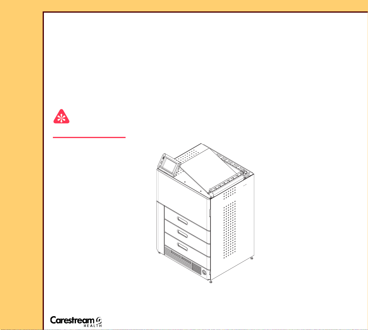
Kodak DryView 6800 LASER IMAGER
Service Code: 1649
Qualified service personnel must repair this equipment.
© Carestream Health, Inc., 2007
Page 2

THEORY GUIDE
This equipment includes parts and assemblies sensitive to damage from electrostatic
discharge. Use caution to prevent damage during all service procedures.
Description Page
30JUL07
8F2924
Page
2 of 72
PLEASE NOTE The information contained herein is based on the experience and knowledge relating to the
subject matter gained by Carestream Health, Inc., prior to publication.
No patent license is granted by this information.
Carestream Health, Inc., reserves the right to change this information without notice, and
makes no warranty, express or implied, with respect to this information. Carestream Health,
Inc., shall not be liable for any loss or damage, including consequential or special damages,
resulting from any use of this information, even if loss or damage is caused by Carestream
Health, Inc., negligence or other fault.
Table of Contents
Equipment Description. . . . . . . . . . . . . . . . . . . . . . . . . . . . . . . . . . . . . . . . . . . . . . . . . . 5
System Overview . . . . . . . . . . . . . . . . . . . . . . . . . . . . . . . . . . . . . . . . . . . . . . . . . . 5
Main Assemblies . . . . . . . . . . . . . . . . . . . . . . . . . . . . . . . . . . . . . . . . . . . . . . . 5
Film Path . . . . . . . . . . . . . . . . . . . . . . . . . . . . . . . . . . . . . . . . . . . . . . . . . . . . . 7
Main Steps in the Film Path. . . . . . . . . . . . . . . . . . . . . . . . . . . . . . . . . . . . . . 8
System Organization . . . . . . . . . . . . . . . . . . . . . . . . . . . . . . . . . . . . . . . . . . . . . . . 9
Overview. . . . . . . . . . . . . . . . . . . . . . . . . . . . . . . . . . . . . . . . . . . . . . . . . . . . . . 9
DICOM RASTER ENGINE (DRE) . . . . . . . . . . . . . . . . . . . . . . . . . . . . . . . . . . 10
MCS. . . . . . . . . . . . . . . . . . . . . . . . . . . . . . . . . . . . . . . . . . . . . . . . . . . . . . . . . . 10
Power Module . . . . . . . . . . . . . . . . . . . . . . . . . . . . . . . . . . . . . . . . . . . . . . . . . 10
DICOM RASTER ENGINE (DRE) . . . . . . . . . . . . . . . . . . . . . . . . . . . . . . . . . . . . . . . . . . 11
Local Panel . . . . . . . . . . . . . . . . . . . . . . . . . . . . . . . . . . . . . . . . . . . . . . . . . . . . . . . . . . . 14
Machine Control System (MCS) . . . . . . . . . . . . . . . . . . . . . . . . . . . . . . . . . . . . . . . . . . 16
MCS Functions . . . . . . . . . . . . . . . . . . . . . . . . . . . . . . . . . . . . . . . . . . . . . . . . . . . . 16
MCS Hardware. . . . . . . . . . . . . . . . . . . . . . . . . . . . . . . . . . . . . . . . . . . . . . . . . . . . . 16
2
I
C BUS . . . . . . . . . . . . . . . . . . . . . . . . . . . . . . . . . . . . . . . . . . . . . . . . . . . . . . . . . . 17
Communication Between MICRO BOARDS . . . . . . . . . . . . . . . . . . . . . . . . . . . . . 18
Optics Module . . . . . . . . . . . . . . . . . . . . . . . . . . . . . . . . . . . . . . . . . . . . . . . . . . . . . 19
Components Controlled or Sensed by the MICROBOARDS . . . . . . . . . . . . . . . 19
POWER DISTRIBUTION BOARD . . . . . . . . . . . . . . . . . . . . . . . . . . . . . . . . . . . . . . . . . . 23
Functions . . . . . . . . . . . . . . . . . . . . . . . . . . . . . . . . . . . . . . . . . . . . . . . . . . . . . . . . . 23
Power Distribution . . . . . . . . . . . . . . . . . . . . . . . . . . . . . . . . . . . . . . . . . . . . . . . . . 23
I2C Bus. . . . . . . . . . . . . . . . . . . . . . . . . . . . . . . . . . . . . . . . . . . . . . . . . . . . . . . . . . . 23
MICROPROCESSOR FUNCTIONS . . . . . . . . . . . . . . . . . . . . . . . . . . . . . . . . . . . . . 24
Page 3

THEORY GUIDE
30JUL07
8F2924
Page
3 of 72
Application Software. . . . . . . . . . . . . . . . . . . . . . . . . . . . . . . . . . . . . . . . . . . . 25
Door Latch Motor . . . . . . . . . . . . . . . . . . . . . . . . . . . . . . . . . . . . . . . . . . . . . . 25
Unlock Functions . . . . . . . . . . . . . . . . . . . . . . . . . . . . . . . . . . . . . . . . . . . . . . 25
Turnaround Motor . . . . . . . . . . . . . . . . . . . . . . . . . . . . . . . . . . . . . . . . . . . . . . 26
INTERLOCK SYSTEM . . . . . . . . . . . . . . . . . . . . . . . . . . . . . . . . . . . . . . . . . . . . . . . 27
ROLLBACK/PICKUP ASSEMBLIES . . . . . . . . . . . . . . . . . . . . . . . . . . . . . . . . . . . . . . . . 30
Film Registration Assembly. . . . . . . . . . . . . . . . . . . . . . . . . . . . . . . . . . . . . . . . . . . . . . 31
PURPOSE . . . . . . . . . . . . . . . . . . . . . . . . . . . . . . . . . . . . . . . . . . . . . . . . . . . . . 31
FILM PATH . . . . . . . . . . . . . . . . . . . . . . . . . . . . . . . . . . . . . . . . . . . . . . . . . . . . 33
REGISTRATION ASSEMBLY . . . . . . . . . . . . . . . . . . . . . . . . . . . . . . . . . . . . . 33
Registration Component Functions . . . . . . . . . . . . . . . . . . . . . . . . . . . . . . . 36
Electrical Components . . . . . . . . . . . . . . . . . . . . . . . . . . . . . . . . . . . . . . . . . . 37
HOW THE REGISTRATION SUBSYSTEM FUNCTIONS . . . . . . . . . . . . . . . . 38
OPTICS/EXPOSURE TRANSPORT ASSEMBLY . . . . . . . . . . . . . . . . . . . . . . . . . . . . . . 40
OPTICS ASSEMBLY . . . . . . . . . . . . . . . . . . . . . . . . . . . . . . . . . . . . . . . . . . . . . . . . . . . . 41
Internal Configuration . . . . . . . . . . . . . . . . . . . . . . . . . . . . . . . . . . . . . . . . . . . . . . 41
OPTICAL COMPONENTS . . . . . . . . . . . . . . . . . . . . . . . . . . . . . . . . . . . . . . . . . . . . 42
OPTICS AY ELECTRONICS . . . . . . . . . . . . . . . . . . . . . . . . . . . . . . . . . . . . . . . . . . 45
“Imaging” Process . . . . . . . . . . . . . . . . . . . . . . . . . . . . . . . . . . . . . . . . . . . . . . . . . 47
EXPOSURE TRANSPORT AY. . . . . . . . . . . . . . . . . . . . . . . . . . . . . . . . . . . . . . . . . . . . . 50
Function . . . . . . . . . . . . . . . . . . . . . . . . . . . . . . . . . . . . . . . . . . . . . . . . . . . . . . . . . . 50
How It Works . . . . . . . . . . . . . . . . . . . . . . . . . . . . . . . . . . . . . . . . . . . . . . . . . . . . . . 52
EXPOSURE TRANSPORT CONTROL SYSTEM . . . . . . . . . . . . . . . . . . . . . . . . . . 55
ISOLATION PLATE . . . . . . . . . . . . . . . . . . . . . . . . . . . . . . . . . . . . . . . . . . . . . . . . . . . . . 58
THERMAL PROCESSOR. . . . . . . . . . . . . . . . . . . . . . . . . . . . . . . . . . . . . . . . . . . . . . . . . 59
Purpose . . . . . . . . . . . . . . . . . . . . . . . . . . . . . . . . . . . . . . . . . . . . . . . . . . . . . . 59
Main Components . . . . . . . . . . . . . . . . . . . . . . . . . . . . . . . . . . . . . . . . . . . . . . 60
Transport Within the PROCESSOR. . . . . . . . . . . . . . . . . . . . . . . . . . . . . . . . 60
SLACKLOOP AY . . . . . . . . . . . . . . . . . . . . . . . . . . . . . . . . . . . . . . . . . . . . . . . 61
DRUM . . . . . . . . . . . . . . . . . . . . . . . . . . . . . . . . . . . . . . . . . . . . . . . . . . . . . . . . 61
FLATBED . . . . . . . . . . . . . . . . . . . . . . . . . . . . . . . . . . . . . . . . . . . . . . . . . . . . . 61
COOLING SECTION. . . . . . . . . . . . . . . . . . . . . . . . . . . . . . . . . . . . . . . . . . . . . 62
PROCESSOR CONTROL BOARD. . . . . . . . . . . . . . . . . . . . . . . . . . . . . . . . . 62
AIRFLOW in the PROCESSOR . . . . . . . . . . . . . . . . . . . . . . . . . . . . . . . . . . . 65
APPLICATION SOFTWARE . . . . . . . . . . . . . . . . . . . . . . . . . . . . . . . . . . . . . . 66
“Initialization” . . . . . . . . . . . . . . . . . . . . . . . . . . . . . . . . . . . . . . . . . . . . . 67
Operation . . . . . . . . . . . . . . . . . . . . . . . . . . . . . . . . . . . . . . . . . . . . . . . . . 67
Diagnostics . . . . . . . . . . . . . . . . . . . . . . . . . . . . . . . . . . . . . . . . . . . . . . . 67
Temperature Offsets . . . . . . . . . . . . . . . . . . . . . . . . . . . . . . . . . . . . . . . . . . . . 67
POWER MODULE . . . . . . . . . . . . . . . . . . . . . . . . . . . . . . . . . . . . . . . . . . . . . . . . . . . . . . 68
Physical Layout. . . . . . . . . . . . . . . . . . . . . . . . . . . . . . . . . . . . . . . . . . . . . . . . . . . . 68
Page 4

THEORY GUIDE
30JUL07
8F2924
Page
4 of 72
Functions . . . . . . . . . . . . . . . . . . . . . . . . . . . . . . . . . . . . . . . . . . . . . . . . . . . . . . . . . 69
Fault Protection in the POWER MODULE . . . . . . . . . . . . . . . . . . . . . . . . . . . . . . 71
Publication History . . . . . . . . . . . . . . . . . . . . . . . . . . . . . . . . . . . . . . . . . . . . . . . . . . . . . 72
Page 5
30JUL07
FILM SUPPLY
DRAWERS
POWER MODULE
TURNAROUND
PROCESSOR
PROCESSOR
FLATBED
EXPOSURE
TRANSPORT
OPTICS
DRUM
ASSEMBLY
REGISTRATION
ASSEMBLY
DRE
PROCESSOR
COOLING SECTION
ACCUMULATOR
LOCAL
PANEL
SORTER
Laser Beam
8F2924
Page
5 of 72
THEORY GUIDE Equipment Description
Section 1: Equipment Description
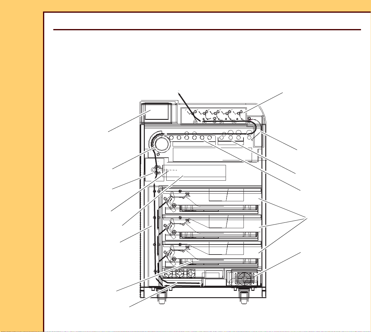
System Overview
Main Assemblies
Figure 1 shows the main parts of the IMAGER:
Figure 1
Page 6

30JUL07
8F2924
Page
6 of 72
THEORY GUIDE Equipment Description
FILM SUPPLY
DRAWERS
Each DRAWER holds a film cartridge. The PICKUP
ASSEMBLY in the DRAWER feeds film to the
REGISTRATION ASSEMBLY. There can be 1,2 or 3
DRAWERS.
REGISTRATION
Orients film for the EXPOSURE TRANSPORT.
ASSEMBLY
EXPOSURE
TRANSPORT
Moves the film line by line past the scanning laser
beam.
OPTICS MODULE Generates a scanning laser beam that exposes the
film.
PROCESSOR
Rapidly heats the film to processing temperature.
DRUM
PROCESSOR
FLATBED
Keeps the temperature of the film until image is fully
developed.
PROCESSOR
Stops emulsion development and hardens the “base”.
COOLING SECTION
TURNAROUND Routes developed film to the SORTER or OUTPUT
TRAY.
SORTER Places film in 1 of 5 SORTER BINS. You can
configure the IMAGER to route films from each
connected MODALITY to a different BIN.
The SORTER is optional. If the IMAGER does not
have a SORTER, all completed films are sent to 1
OUTPUT TRAY.
- DICOM RASTER
ENGINE
A computer that runs the MIM software and the
MACHINE CONTROL SYSTEM (MCS) software that
controls the IMAGER.
Page 7
THEORY GUIDE Equipment Description
30JUL07
8F2924
Page
7 of 72
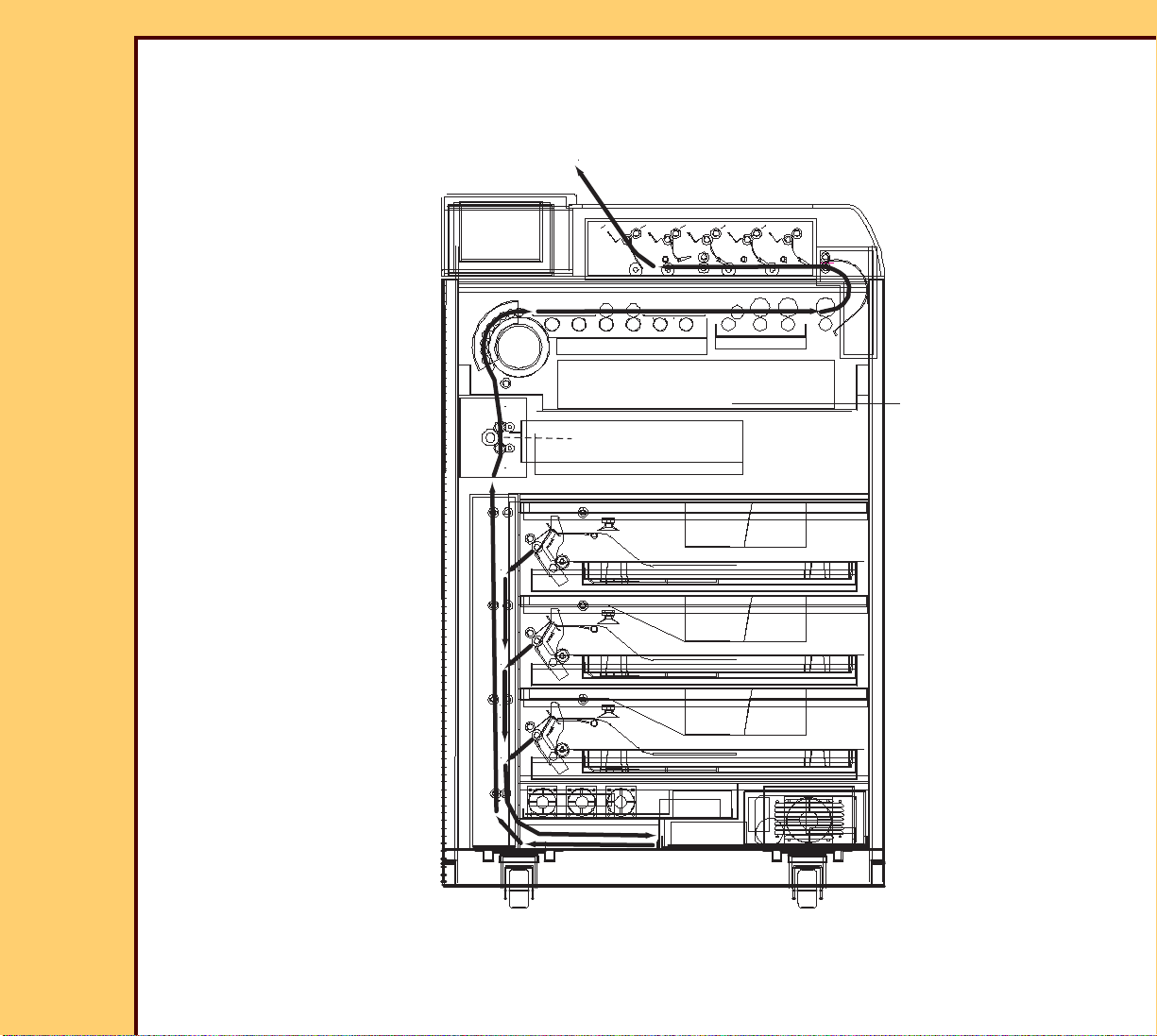
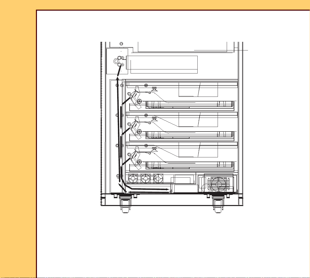
Film Path
Figure 2 shows the film path within the IMAGER.
Figure 2
Page 8

30JUL07
8F2924
Page
8 of 72
THEORY GUIDE Equipment Description
Main Steps in the Film Path
1. The MCS places an image into the IMAGE MEMORY on the DATAPATH
BOARD.
2. One of the PICKUP ASSEMBLIES feeds a sheet of film to the REGISTRATION
AY.
3. ROLLERS in the REGISTRATION AY move the film down until the trailing edge
of the film clears the PICKUP AY and is vertical. Depending on the size of the
film and the film DRAWER it comes from, the film might or might not extend all
the way into the ACCUMULATOR.
4. ROLLERS in the REGISTRATION AY reverse direction and feed film from the
ACCUMULATOR.
5. The film is “centered” and “deskewed” in the REGISTRATION AY.
6. ROLLERS in the REGISTRATION AY feed film up to the EXPOSURE
TRANSPORT.
7. The DATAPATH BOARD starts to read the image from IMAGE MEMORY “line-
by-line” and sends each line to the OPTICS MODULE. The OPTICS MODULE
generates a scanning laser beam for each image line.
8. ROLLERS in the EXPOSURE TRANSPORT move the film past the horizontal
scanning laser beam that exposes the film.
9. The leading edge of the film reaches the heated PROCESSOR DRUM and
starts to develop when the “lower” part of the film is moving through the
EXPOSURE TRANSPORT.
10. The film is moved through the THERMAL PROCESSOR by the rotating DRUM
and a series of ROLLERS. In the PROCESSOR:
- The DRUM rapidly heats the film to about 129 ° C.
- The film then moves through the heated FLATBED SECTION which
maintains a slightly lower temperature and completes processing the film.
- The film moves through the COOLING SECTION to remove heat from the
film to prevent density variations.
11. The developed film enters the TURN-AROUND which changes the film
direction and discharges it to the SORTER or EXIT TRAY.
Page 9
THEORY GUIDE Equipment Description
DRE
Modalities
DICOM
DRE
LOCAL
PANEL
Touchscreen Input
Image Data
DC Power
Customer
Network
DC PowerAC Power
AC Power
Speaker
Power Switch
POWER MODULE
AC Power
In
DRE
COMPUTER
Image
Control/
Status
USB Channel
MCS
(Print Engine)
30JUL07
8F2924
Page
9 of 72
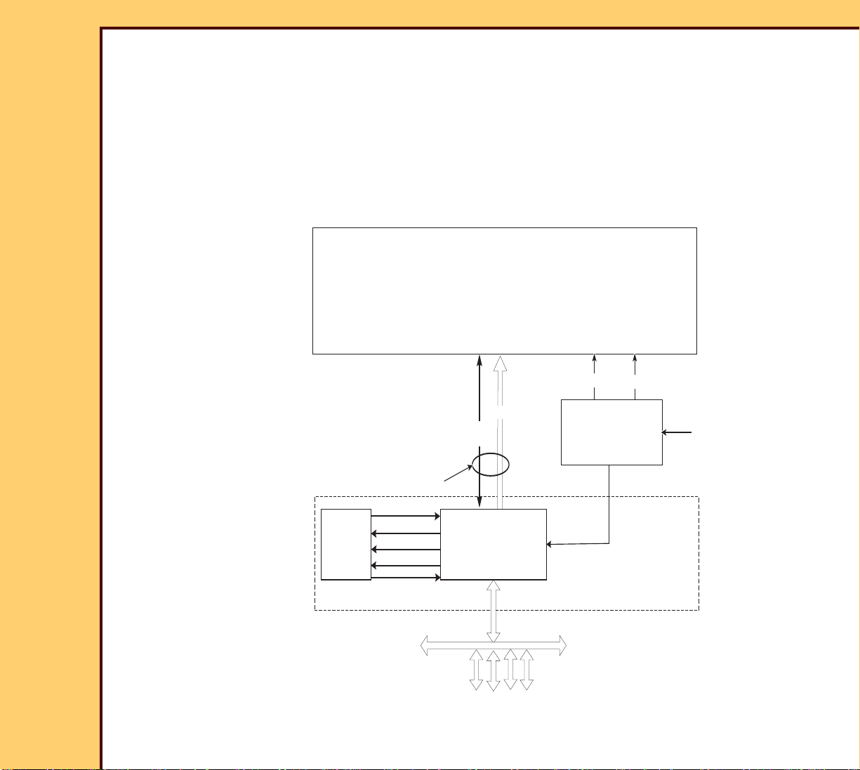
System Organization
Overview
The IMAGER has 3 main parts:
• The DICOM RASTER ENGINE (DRE)
• The MACHINE CONTROL SYSTEM (MCS)
• The POWER MODULE
Page 10

30JUL07
8F2924
Page
10 of 72
THEORY GUIDE Equipment Description
DICOM RASTER ENGINE (DRE)
The DRE system consists of the DRE COMPUTER and the LOCAL PANEL.
The DRE COMPUTER is a compact Pentium PC that runs the Microsoft Windows
XP operating system and several modules of the 6800 application software. With
the application software, the DRE functions as a MIM print server, within the
IMAGER, where the MCS is the print destination.
The DRE COMPUTER is responsible for acquiring print jobs from modalities on
the customer’s network and for queueing and rendering the incoming print jobs.
Formatted print jobs are forwarded, over a USB connection, to the MCS for
printing. The DRE COMPUTER also communicates with the LOCAL PANEL and
runs service tool software that can be accessed with a SERVICE PC.
The LOCAL PANEL is an 8 by 10-in. color FLAT PANEL DISPLAY that serves as
the operator interface for the IMAGER. In addition to the DISPLAY, it includes a
TOUCHSCREEN, a SPEAKER and a POWER SWITCH. Images displayed on the
LOCAL PANEL are sent from the DRE COMPUTER and TOUCHSCREEN
commands are sent to the DRE COMPUTER for interpretation and action.
MCS
The MCS is the “print engine” within the IMAGER. It receives formatted images
from the DRE and performs all of the electrical and mechanical functions
necessary to transport, expose and develop DryView film.
Power Module
The POWER MODULE supplies +5 V and +24 V DC power to the MCS
electronics and 120 V AC power to the DRE and to the HEATERS in the
THERMAL PROCESSOR. Input power can range from 90 to 250 V AC. For
energy saving purposes, the POWER MODULE includes a control input that
allows the DRE COMPUTER to shut off DC power to the MCS electronics and AC
power to the THERMAL PROCESSOR HEATERS.
For more information see POWER MODULE.
Page 11

30JUL07
8F2924
Page
11 of 72
THEORY GUIDE DICOM RASTER ENGINE (DRE)
Section 2: DICOM RASTER ENGINE (DRE)
The DRE is a PERSONAL COMPUTER (PC) with the Microsoft Windows XP Embedded
operating system. It runs application software that functions as a MIM PRINT SERVER and
software that prepares images for printing.
The DRE connects to the customer’s LOCAL AREA NETWORK and is responsible for
acquiring, queueing and rendering images from DICOM modalities on the LAN. Rendered
images are sent to the MCS for printing.
A single USB cable connects the DRE to the MCS. The USB interface can transfer several
channels of data simultaneously. It concurrently transfers commands, image data and
configuration from the DRE to the MCS. At the same time it transfers and status information
and diagnostic information returned from the MCS.
The DRE is mounted on a tray that slides out of the IMAGER for service. The main
components are
• PC MOTHERBOARD with a 1.6 GHz (or better) Intel Pentium M PROCESSOR
• A NETWORK BOARD in a PCI slot on the MOTHERBOARD
• HARD DRIVE
• DVD/CD DRIVE
• DC POWER SUPPLY for the MOTHERBOARD and accessories
• Cooling FAN
• INPUT CF BOARD - This BOARD performs 2 functions
– It provides an adaptor for a COMPACT FLASH (CF) CARD that connects to the IDE
controller on the MOTHERBOARD.
– It provides a service interface to the DRE. There are 3 CONNECTORS for service
tools:
> An RJ45 NETWORK CONNECTOR to connect a LAPTOP COMPUTER
> A USB CONNECTOR for connecting a USB MOUSE
> A PS2 CONNECTOR for connecting a KEYBOARD
Page 12
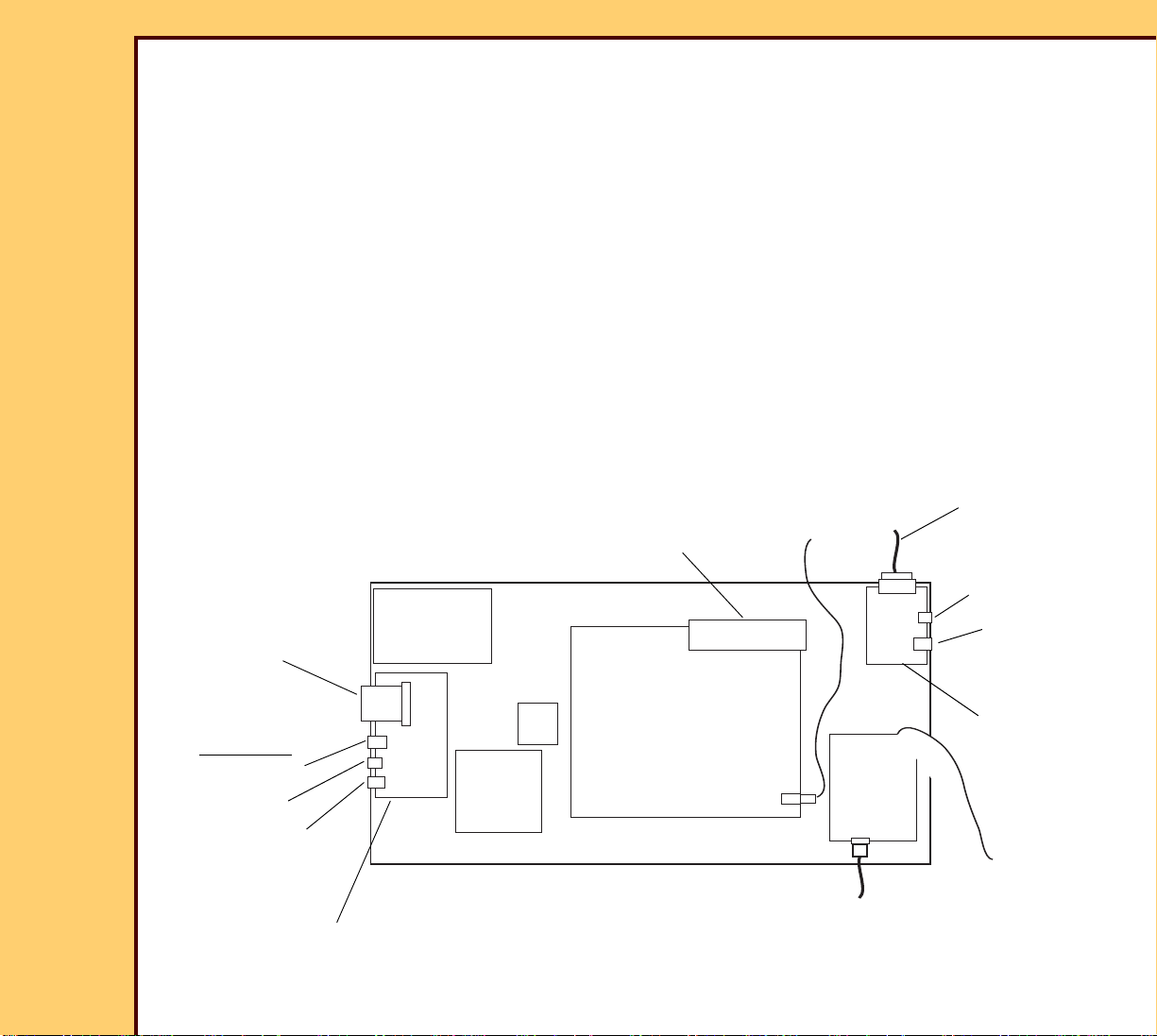
THEORY GUIDE DICOM RASTER ENGINE (DRE)
COMPACT
CARD
FLASH
DVD/CD
DRIVE
NETWORK
USB
KEYBOARD
CONNECTORS
INPUT CF
BOARD
FRONT
DC
POWER
SUPPLY
120 V AC
From POWER
MODULE
HARD
DRIVE
FAN
MOTHER
BOARD
LOCAL PANEL
USB
CONNECTOR
NETWORK
CONNECTOR
LVDS
BOARD
CABLE to
DATAPATH
USB CABLE to
BOARD
(for customer
network)
(for Service)
12 Volt Wake Up
Signal to the Power
Module
NETWORK
BOARD
30JUL07
8F2924
Page
12 of 72
• LVDS BOARD -This BOARD provides an interface between the MOTHERBOARD and the
LOCAL PANEL. It also provides 2 external connectors:
– An RJ45 NETWORK CONNECTOR for connecting the IMAGER to the customer’s
Ethernet/DICOM network
– A USB CONNECTOR for future use
A 26-pin cable connects the LVDS BOARD to the LOCAL PANEL. This cable carries the
image data for the LCD PANEL, input data from the TOUCH SCREEN, backlight brightness
signal, audio for the SPEAKER, +3.3, +5 and +12 V DC power, and a signal from the
POWER BUTTON on the LOCAL PANEL. LVDS is an abbreviation for “Low Voltage
Differential Signaling”, the transmission method used to send image data from the LVDS
BOARD to the LOCAL PANEL.
The following diagram shows the main components in the DRE and the external connection
points on the DRE.
Page 13

THEORY GUIDE DICOM RASTER ENGINE (DRE)
Note
30JUL07
8F2924
Page
13 of 72
The COMPACT FLASH (CF) CARD is used to backup and restore the IMAGER configuration
parameters. It also holds data required for startup and should not be removed or replaced
unless directed by a MODIFICATION INSTRUCTION or other approved procedure. The
IMAGER will not start up if the CF CARD is not present.
The DC POWER SUPPLY in the DRE supplies power to the MOTHER BOARD, HARD
DRIVE and DVD/CD DRIVE. A 12 V DC output from the DRE POWER SUPPLY serves as a
wake up signal to the IMAGER POWER MODULE.
The DRE POWER SUPPLY is controlled by the MOTHERBOARD. A logic signal from the
MOTHERBOARD turns the DRE POWER SUPPLY ON and OFF.
• When the IMAGER is “Ready” or in the “Energy Save” or “Sleep” modes, the
MOTHERBOARD turns the DRE POWER SUPPLY ON. The POWER SUPPLY provides
+3.3, +5, +12, and -12 V DC and the DRE is fully functional.
• When the IMAGER is in the “Power Off” state, the MOTHERBOARD turns off the DRE
POWER SUPPLY. In this condition, the POWER SUPPLY provides only +5 V DC standby
power to the MOTHERBOARD. Most functions on the MOTHERBOARD are suspended
but the 5V standby power enables the MOTHERBOARD to wakeup with a signal from the
POWER BUTTON on the LOCAL PANEL or from the Power Schedule set up on the
LOCAL PANEL.
The DRE POWER SUPPLY receives 120 V AC input power from the POWER MODULE. The
POWER SWITCH on the POWER MODULE must be ON for the DRE POWER SUPPLY to
supply either full power or +5 V standby power.
Page 14

30JUL07
8F2924
Page
14 of 72
THEORY GUIDE Local Panel
Section 3: Local Panel
The LOCAL PANEL, which connects by a CABLE to the LVDS BOARD in the DRE, contains:
• An LCD DISPLAY with miniature fluorescent BACKLIGHTS
• A TOUCH PANEL
• An DC-to-AC INVERTER POWER SUPPLY for the BACKLIGHTS
• A SPEAKER
• A momentary POWER SWITCH
• A LOCAL PANEL INTERFACE BOARD that connects to the to the LVDS BOARD in the
DRE
The LOCAL PANEL is not repaired in the field: it is replaced as a unit.
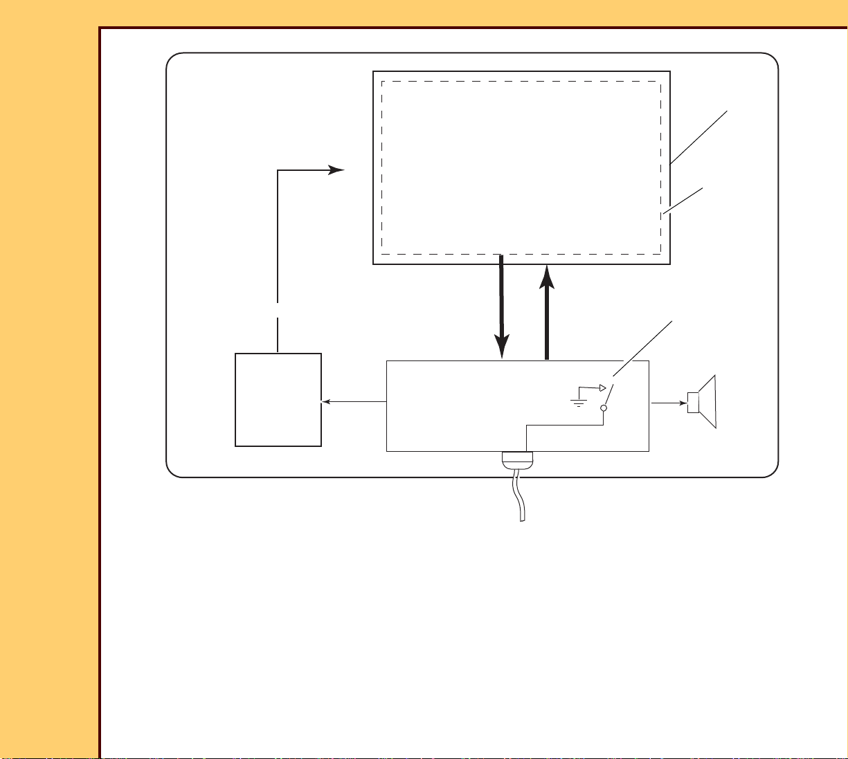
The following graphic is a block diagram of the LOCAL PANEL.
Page 15
30JUL07
+12 V DC
To BACKLIGHTS
100 V AC
TOUCH PANEL
LCD PANEL
To DRE
INVERTER
DC-to-AC
SPEAKER
MOMENTARY SWITCH
(POWER BUTTON)
LOCAL PANEL
INTERFACE BOARD
LOCAL
PANEL
8F2924
Page
15 of 72
THEORY GUIDE Local Panel
The cable that connects the LOCAL PANEL to the DRE carries:
• Image data for the LCD DISPLAY PANEL
• Input data from the TOUCH PANEL
• Closure signal (ground) from the MOMENTARY SWITCH
• Audio signal to the SPEAKER
• A backlight dimming signal
• +3.3, +5, and +12 V DC power
Page 16

30JUL07
8F2924
Page
16 of 72
THEORY GUIDE Machine Control System (MCS)
Section 4: Machine Control System (MCS)
The MCS is the print engine within the IMAGER. It is made up of both hardware and software
components.
MCS Functions
The MCS receives image data and commands from the DRE over the USB interface and is
responsible for controlling the mechanical and optics assemblies to transport, expose and
develop films. Once the DRE sends an image and print command, the MCS performs the
actions necessary to expose and print a film largely independent of the DRE.
MCS Hardware
The MCS hardware consists of several electro-mechanical subsystems, each controlled by a
“MICRO BOARD” - a circuit board containing a MICROPROCESSOR. Software in each
MICRO BOARD provides the control “intelligence” for the subsystems. An I2C BUS connects
a master MICROPROCESSOR on the DATAPATH BOARD to all of the other MICRO
BOARDS. The BUS is used to exchange commands and status information between the
master MICROPROCESSOR and the MICROROCESSORS on the other MICRO BOARDS.
The master MICROPROCESSOR controls the subordinate MICROBOARDS by sending
commands and receiving status information on the I2C BUS. Each MICROBOARD controls
the functions of its mechanical subsystem by controlling motors and reading sensors.
The following diagram shows how the MICROBOARDS are connected on the I2C BUS. The
DATAPATH MICROPROCESSOR is the primary control device with all other
MICROPROCESSORS subordinate.
Page 17
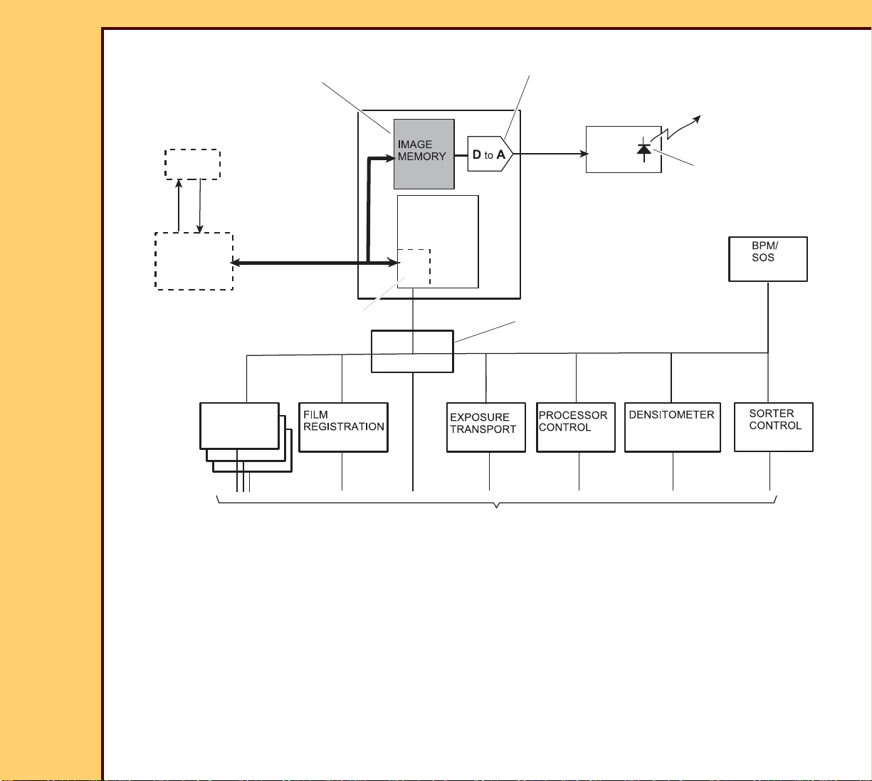
30JUL07
FILM
SUPPLY
LASER DRIVER
BOARD
POWER DISTRIBUTION
BOARD
USB
LOCAL
PA NE L
I2C
I2C
I2C
Modulated Laser
Beam - To Optics
DATAPATH BOARD
CONTROL
BOARDS
BOARD
BOARD
BOARD
BOARD
BOARD
BOARD
Laser Diode
Capacity:
1 Image
Digital - to - analog
conversion
To : MOTORS, HEATERS, SENSORS controlled or sensed by the MICROBOARDS
TRANSLATION
USB/I2C
DRE
PRIMARY
MICROPROCESSOR
8F2924
Page
17 of 72
THEORY GUIDE Machine Control System (MCS)
I2C BUS
The I2C is a low-speed, serial BUS with only 2 lines (plus ground). The BUS interconnects all
of the MICROBOARDS.The MICROCONTROLLERS and FLASH MEMORIES on the
MICROBOARDS connect to the BUS. Each device connected to the BUS has a unique
address.
Page 18

THEORY GUIDE Machine Control System (MCS)
30JUL07
8F2924
Page
18 of 72
The BUS is bidirectional. Any of the MICROPROCESSORS can initiate a data transfer on the
BUS. Several types of information are transferred on the BUS:
• Commands - These are sent from the MASTER MICROPROCESSOR, on the DATAPATH
BOARD, to cause a slave MICROPROCESSOR to perform an action, for example, to
“Execute Diagnostics” stored in the slave CPU. A command causes the slave to reply,
acknowledging that the command can be processed or that there is a problem which
prevents processing the command.
• MICROBOARDS return responses to commands to the DATAPATH BOARD.
• MICROBOARDS send status information to the DATAPATH BOARD.
• Software updates are downloaded to the MICROBOARDS.
Communication Between MICRO BOARDS
Communication between the DRE and the 11 MICRO-BOARDS is conducted over a USB
channel and an I2C bus. The 11 MICRO-BOARDS are all connected on a common I2C bus.
This bus is used to send commands from the DRE to the MICRO-BOARDS and return
responses from the MICRO-BOARDS. It is also used to load software or other data into
MICROPROCESSOR MEMORIES or NVRAM on the MICRO-BOARDS.
The I2C INTERFACE is a 2-wire BUS having a Serial Data, SDA, and a Serial Clock (SCL)
line. These wires connect information between the devices and the CPUs connected to the
BUS. Each CPU on the BUS is recognized by a unique address and can either receive or
transmit data. The CPU that starts a data transfer is a “master” and the receiving CPU is a
“slave.” Any of the CPUs on the BUS can be either a master or a slave. In practice, the
MASTER CPU will start all commands, and will normally be the master, and the CPUs for
modules on the BUS will be slaves. Three types of messages are used:
• Commands - These are sent from the MASTER CPU to cause a slave CPU to perform an
action, for example, to “Execute Diagnostics” stored in the slave CPU. A command causes
the slave to reply, acknowledging that the command can be processed or that there is a
problem which prevents processing the command.
• Replies - The slave must respond with a reply after each byte of a received command. If
the MASTER does not receive a reply within 100 ms after sending the command, it will
stop the process.
Page 19

THEORY GUIDE Machine Control System (MCS)
30JUL07
8F2924
Page
19 of 72
• Notification - These are sent from a slave CPU to the MASTER CPU indicating a changed
condition in the slave module.
Each type of message must be preceded by the address of the CPU for which it is intended.
Optics Module
Components Controlled or Sensed by the MICROBOARDS
The IMAGER has a number of rotary and linear MOTORS that power the functions of the
IMAGER and SENSORS. The SENSORS provide input to MICROPROCESSORS that control
the MOTORS.
Figure 3 shows the approximate location of MOTORS and SENSORS in the IMAGER. Table
1 and Table 2 provide descriptions each MOTOR and SENSOR.
Page 20
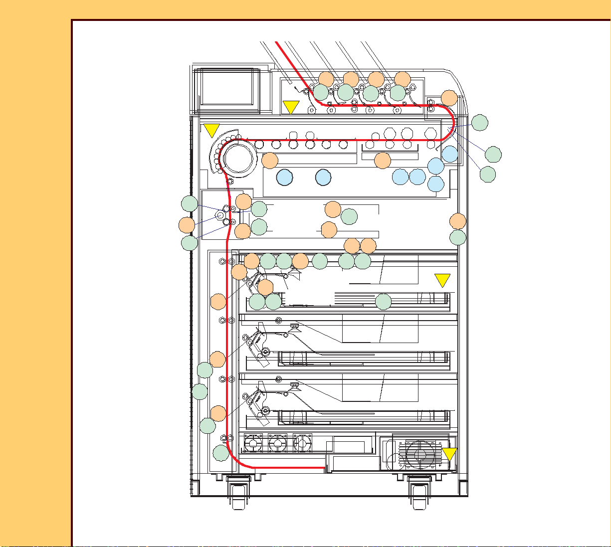
THEORY GUIDE Machine Control System (MCS)
F5 F6
S12
S1 S2S3S4 S5
S6 S7S8
S9
S10
S11
S13
S14
S15
M1
M2
M3
M4 M5
M6
M7
M8
M9
M10
M11
M12
M13 M14
M15
M16M17
M18M19
F1
F2
F3
S4 - PU Roller Position
M14 - Temp
Cooling Drive
S19
M20
i1
i2
i3
i4
M22
M21
S24
S23 S22
S21
S20
S25
F7
F4
30JUL07
8F2924
Page
20 of 72
Figure 3 MOTORS and SENSORS
Page 21

30JUL07
Note
8F2924
Page
21 of 72
THEORY GUIDE Machine Control System (MCS)
In the following tables: For components in the PICKUP or ROLLBACK ASSEMBLIES, x will
be U, M or L, for the UPPER, MIDDLE or LOWER FILM DRAWER.
Table 1 MOTORS
Designator/
Location
M1x
Pickup
M2x
Pickup
M3x
Pickup
M4x
Pickup
M5x
Pickup
M6
Rollback
M7
Registration
Name Location
PICKUP FEED
ROLLER OPEN/
CLOSE MOTOR
Descriptio
n/
Function
PICKUP ROLLER
Open/
Close
PICKUP ROLLER
drive
PICKUP PICKUP
drive
PICKUP PICKUP
PUMP
PICKUP PICKUP
RELIEF
VALVE
ROLLBACK ROLLBAC
K DRIVE
MOTOR
Registration Centering
MOTOR
Motion Typ e
Rotational DC GEAR
MOTOR
Home/
Default
Home =
Open
Limit =
Close
Rotational STEPPER Off On
Rotational DC GEAR
MOTOR
Home = Up
(film at
feed)
Limit =
Cartridge
bottom
Rotational
Linear
Rotational,
Reversing
STEPPER Home =
ARMS
retracted
actuated
= ARMS
extended
to film
size
Limit
Page 22

THEORY GUIDE Machine Control System (MCS)
30JUL07
8F2924
Page
22 of 72
Table 2 SENSORS
Designator Location
S1x PICKUP Home
SENSOR
Description/
Function
Type Default
Interrupt
SENSOR
Blocked =
PICKUP
home
Sensed
Position
Unblocked =
PICKUP not
home
Page 23

30JUL07
8F2924
Page
23 of 72
THEORY GUIDE POWER DISTRIBUTION BOARD
Section 5: POWER DISTRIBUTION BOARD
Functions
The POWER DISTRIBUTION BOARD (PDB) performs several functions:
• Distributes +5 volt and +24 volt DC power to all other CIRCUIT BOARDS except the DRE
and LOCAL PANEL.
• Provides the logic for the system
• Connects the I2C bus to all of the MICRO BOARDS
• Controls the LATCH MOTOR that unlocks the front DOORS and FILM DRAWERS
• Controls the TURNAROUND MOTOR
Figure 4 on page Page 24 is a block diagram of the PDB.
Power Distribution
The POWER MODULE supplies +5-volt and +24-volt DC power to the PDB. The PDB
provides +5-volt power, either directly or indirectly, to all CIRCUIT BOARDS except the DRE
and LOCAL PANEL. There is no switching or control of +5-volt power on the PDB.
The PDB provides +24-volt power to the MICRO BOARDS subject to inputs from the
INTERLOCK SWITCHES or SERVICE SWITCH. The logic on the PDB may interrupt +24-volt
power to some or all of the MICRO BOARDS depending on the inputs.
I2C Bus
The PDB provides I2C bus connections between the DPB and all the other MICRO BOARDS.
The I2C bus simply passes through the PDB. There is no control or switching of the bus on
the PDB.
Page 24

THEORY GUIDE POWER DISTRIBUTION BOARD
MICROPROCESSOR
INTERLOCK
LOGIC
MOTOR
DRIVER
MOTOR
DRIVER
NVRAM
From DPB
I2C Bus
To a l l M I C R O
BOARDS
+5V
+24V
From Power
MODULE
INTERLOCK
SWITCHES
FILM-AT-ENTRANCE
To F R B
DOOR LATCH
SENSOR
FRONT DOOR
SERVICE
AIR INTAKE
DOOR
LATCH
MOTOR
TURNAROUND
MOTOR
To all CIRCUIT
BOARDS
To M I C R O
BOARDS
I2C Bus
+24V Interlock
Voltages
SWITCH
SORTER
INTERLOCK
FILM DRAWER
JUMPERS
30JUL07
8F2924
Page
24 of 72
Figure 4 PDB Block Diagram
MICROPROCESSOR FUNCTIONS
The MICROPROCESSOR in the PDB controls the DOOR LATCH MOTOR and the
TURNAROUND MOTOR. The MICROPROCESSOR receives an input from the DOOR
LATCH SENSOR and connects to the 2 MOTOR DRIVERS that energize the 2 MOTORS.
Page 25

THEORY GUIDE POWER DISTRIBUTION BOARD
Note
30JUL07
8F2924
Page
25 of 72
The output of the DOOR LATCH SENSOR is low when the FRONT DOOR is locked and high
when the DOOR is unlocked.
Application Software
Application software that runs in the MICROPROCESSOR communicates with the
MCS software to control the 2 MOTORS and report status to the MCS. The
application software also performs initialization tests upon power-up, when a reset
command is received from the MCS or when the RESET SWITCH on the PDB is
pressed. The application software performs MOTOR diagnostic tests and memory
tests when the MCS sends diagnostic commands.
Door Latch Motor
The DOOR LATCH MOTOR is a linear stepper MOTOR that, when energized, lifts
a LATCH ROD. that locks and unlocks the FRONT DOOR and DRAWERS.
The LATCH ROD has 2 positions: up and down. When the ROD is down, the
FRONT DOOR and the FILM DRAWERS are locked and the PROCESSOR
DRAWER is unlocked (but secured by latches on the DRAWER SLIDES). When
the ROD moves up, it unlatches the FRONT DOOR. The DOOR remains
unlatched until it is pushed closed. If the ROD is held up, the FILM DRAWERS are
unlocked but the PROCESSOR DRAWER is locked. This mechanism prevents the
FILM DRAWERS and PROCESSOR DRAWER from being pulled out at the same
time.
The LATCH ROD can be operated manually from inside the AIR INTAKE DOOR.
Unlock Functions
In response to commands from the MCS, the application software controls the
DOOR LATCH MOTOR to perform the following unlock functions.
• When “Unlock Film Supply” is selected on the LOCAL PANEL, the LATCH
MOTOR lifts and holds the LATCH ROD up. The FRONT DOOR and FILM
DRAWERS are unlocked but the PROCESSOR DRAWER is locked. The
LATCH MOTOR holds the ROD up until the FRONT DOOR is closed.
Page 26

THEORY GUIDE POWER DISTRIBUTION BOARD
Note
30JUL07
8F2924
Page
26 of 72
• When “Unlock Processor” is selected on the LOCAL PANEL, the LATCH
MOTOR lifts the ROD briefly to unlatch the FRONT DOOR then immediately
lowers the ROD to lock the FILM DRAWERS. The FRONT DOOR can be
opened and the PROCESSOR DRAWER can be pulled out.
Turnaround Motor
The TURNAROUND MOTOR is a rotary stepper MOTOR that drives ROLLERS in
the TURNAROUND that move film to the SORTER or OUTPUT TRAY. Application
software in the PDB MICROPROCESSOR operates the TURNAROUND MOTOR
in response to commands from the MCS:
1. When a film is exiting the EXPOSURE TRANSPORT, the MCS notifies the
PDB application to “Transport Film to the Densitometer”.
2. A software timer is started to track the progress of film through the
PROCESSOR and toward the TURNAROUND ROLLERS.
3. When the timer indicates that the film is approaching the first TURNAROUND
ROLLER, the application runs the TURNAROUND MOTOR at the same speed
as the PROCESSOR.
4. When the film passes the DENSITOMETER FILM PRESENT SENSOR, S18,
the application delays until the trailing edge of film clears the COOLING
SECTION ROLLERS and then runs the TURNAROUND MOTOR at high speed
to “kick” the film out of the TURNAROUND.
5. The application allows time for the film to exit to the SORTER or OUTPUT
TRAY and then turns off the TURNAROUND MOTOR.
If the film is a calibration sheet, the high-speed “kick” is not started while the film
is in the densitometer.
Page 27

THEORY GUIDE POWER DISTRIBUTION BOARD
Legend
PDB = Component located on the PDB
PMOD = Component located in the POWER MODULE
DPB = Component located on the DPB
V24 = + 24 volts DC
-AVCC = -5volts DC for analog circuits
Jumpers located on the DRAWER-side
of the BLINDMATE CONNECTOR
for each DRAWER
120V AC = 120 volts AC for PROCESSOR HEATERS
30JUL07
8F2924
Page
27 of 72
INTERLOCK SYSTEM
Figure 5 is a simplified diagram of the Interlock circuits. All INTERLOCK SWITCHES must
be closed for the IMAGER to operate normally. Table 3 on Page 28 shows the effect of
opening each INTERLOCK SWITCH.
Components in the INTERLOCK SYSTEM are located on the PDB, the PCB, the DPB and in
the POWER MODULE. For details of cabling between the INTERLOCK SWITCHES and other
interlock components, refer to the FUNCTIONAL BLOCK DIAGRAMS for the IMAGER.
V24
Air Intake
Door Switch
V24
Upper
Drawer
Jumper
Main Door
Switch
NC
PDB
D11
Middle
Drawer
Jumper
V24
Lower
Drawer
Jumper
PDB
K1
PDB
K3
PDB
D8
PDB
V24
K2
Service Switch
(Normal Mode)
NO
V24
DRAWER_HAZARD_24
V24_HAZ
PMOD
K2
120VAC
FILM SUPPLY BOARDS
Upper, Middle, Lower
REGISTRATION BOARD
EXPOSURE TRANSPORT BOARD
PROCESSOR CONTROL BOARD
TURNAROUND MOTOR
LATCH MOTOR
PROCESSOR HEATERS
Sorter
Interlock
Switch
NC
V24
NC
PDB
K4
LASER_HAZARD_24
SORT_HAZ_V24
-AVCC
DPB
K1
Laser
Hazard
Relay
LASER DRIVER
SORTER CONTROL
BOARD
Page 28

THEORY GUIDE POWER DISTRIBUTION BOARD
30JUL07
8F2924
Page
28 of 72
Table 3 INTERLOCK SWITCH ACTIONS
TURNAROUND/
EXPOSURE
INTERLOCK SWITCH
and Condition
SORTER
DIVERTERS
TRANSPORT/
PROCESSOR/
REGISTRATION/
LATCH MOTOR
FILM
SUPPLY
120VAC POWER
to PROCESSOR
MAIN DOOR - Open OFF OFF OFF OFF OFF
SORTER - Open OFF ON ON ON ON
Any DRAWER -
ON ON OFF ON OFF
Open
AIR INTAKE DOOR
ON ON OFF ON OFF
- Open
SERVICE SWITCH -
ON ON ON ON OFF
in Service Mode
All SWITCHES
ON ON ON ON ON
Closed - Normal
Mode
SERVICE SWITCH
ON ON ON ON OFF
Unplugged
LASER
FILM DRAWER INTERLOCK JUMPERS - The BLINDMATE CONNECTOR on each FILM
DRAWER has a JUMPER that acts as an INTERLOCK SWITCH when the DRAWER is
opened. Figure 6 on Page 32 shows how these JUMPERS are connected. If either the
LOWER DOOR ACCESS SWITCH or any of the FILM DRAWERS are open, the interlock
circuit is broken and power to the LASER DRIVER BOARD and FILM SUPPLY BOARDS is
interrupted.
Page 29

THEORY GUIDE POWER DISTRIBUTION BOARD
PDB
K3
1111
10101 24242424 24241 1
1111 1111
10101010
LOWER ACCESS
DOOR SWITCH
V24
Fixed Side
DRAWER
BLINDMATE
CONNECTORS
UPPER
DRAWER
DRAWER
DRAWER
MIDDLE
LOWER
DRAWER
DRAWER
Open
JUMPERS
Interlock Circuit
RELAY controls
power to
Laser and
FILM SUPPLY
BOARDS
Interlock Circuit
Interrupted
Side
30JUL07
8F2924
Page
29 of 72
Figure 5
Page 30

30JUL07
8F2924
Page
30 of 72
THEORY GUIDE ROLLBACK/PICKUP ASSEMBLIES
Section 6: ROLLBACK/PICKUP ASSEMBLIES
To Be Supplied
Page 31

30JUL07
8F2924
Page
31 of 72
THEORY GUIDE Film Registration Assembly
Section 7: Film Registration Assembly
PURPOSE
The purpose of the FILM REGISTRATION SUBSYSTEM is to orient a sheet of
film for entry to the EXPOSURE TRANSPORT. The film is positioned so that:
• Notch is down
• Emulsion towards the OPTICS MODULE
• Film is “centered” on the EXPOSURE TRANSPORT ROLLERS.
• Film is “deskewed” - vertical edges of the film are aligned, parallel with film
direction.
The FILM REGISTRATION SUBSYSTEM has:
• FILM REGISTRATION AY
• ACCUMULATOR
• FILM REGISTRATION CIRCUIT BOARD
• FILM REGISTRATION application software that runs in a MICROPROCESSOR
on the FILM REGISTRATION BOARD
The FILM REGISTRATION BOARD is connected to a number of electrical
components within the FILM REGISTRATION AY:
• VERTICAL TRANSPORT MOTOR - operates the 4 DRIVE ROLLERS.
• FILM CENTERING MOTOR - operates the CENTERING FINGERS.
• FILM CLAMPING MOTOR - opens and closes the NIP ROLLERS for the top 3
drive ROLLER pairs.
• HOME POSITION SENSOR for FILM CENTERING MOTOR
• HOME POSITION SENSOR for CLAMPING MOTOR
• FILM POSITION SENSOR in the ACCUMULATOR
The FILM REGISTRATION application controls film registration functions by
operating the 3 MOTORS in the assembly, based on commands from the MCS
and inputs from the 3 SENSORS in the FILM REGISTRATION AY.
Page 32

THEORY GUIDE Film Registration Assembly
REGISTRATION
ASSEMBLY
ACCUMULATOR
EXPOSURE
TRANSPORT
DRIVE
ROLLER SETS (4)
FILM GUIDE
30JUL07
8F2924
Page
32 of 72
The following drawing shows the position of the FILM REGISTRATION ASSEMBLY
and ACCUMULATOR.
Figure 6
Page 33
THEORY GUIDE Film Registration Assembly
30JUL07
8F2924
Page
33 of 72
FILM PATH
Figure 7 shows the film path through the FILM REGISTRATION SUBSYSTEM.
Figure 7
REGISTRATION ASSEMBLY
The following 2 graphics show the main components in the FILM REGISTRATION
AY.
Page 34
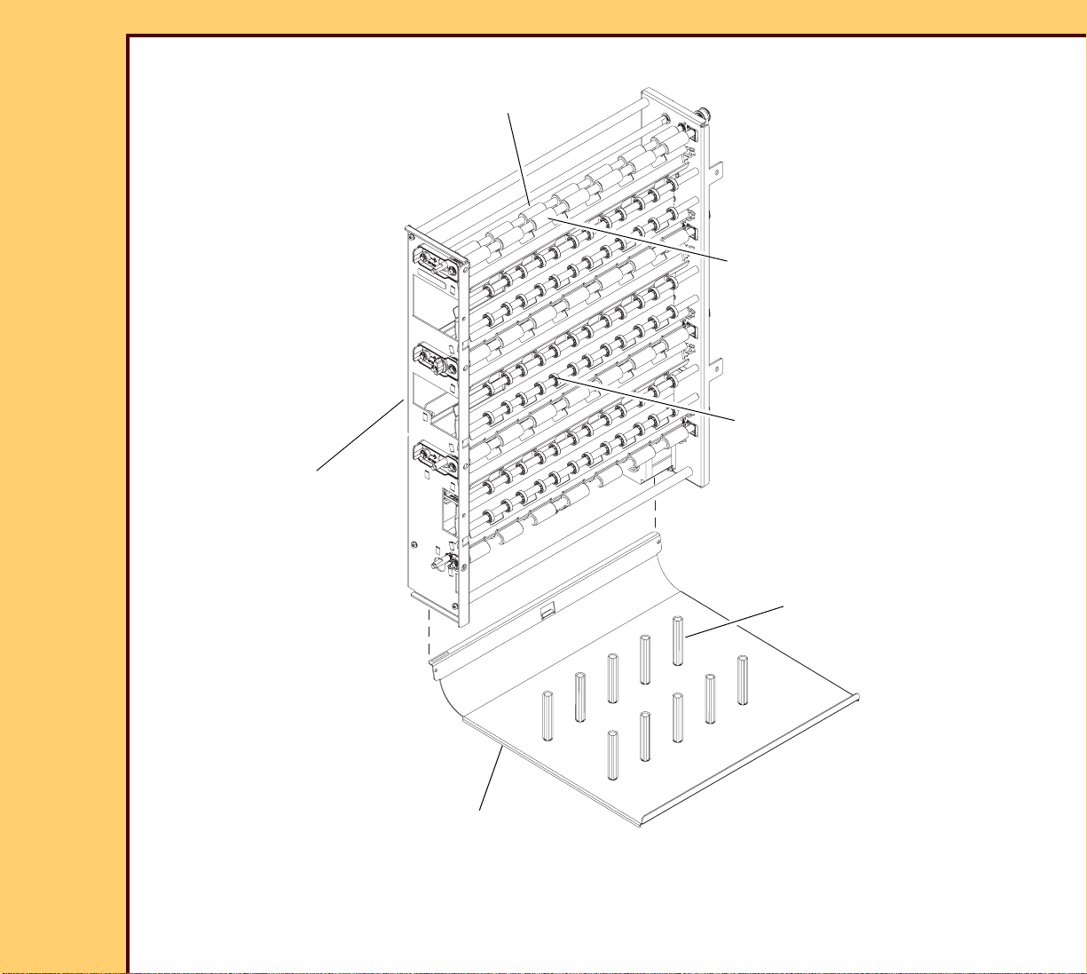
THEORY GUIDE Film Registration Assembly
REGISTRATION
ASSEMBLY
ACCUMULATOR
DRIVE
ROLLERS (4)
NON-POWERED
NIP ROLLERS (4)
IDLER
ROLLERS (6)
GROOVES
30JUL07
8F2924
Page
34 of 72
Figure 8 REGISTRATION ASSEMBLY - VIEW FACING FILM SUPPLY DRAWERS
Page 35

THEORY GUIDE Film Registration Assembly
REGISTRATION
CENTERING MOTOR - M7
TRANSPORT
MOTOR - M8
ROLLER ACTUATOR
MOTOR M9
ACCUMULATOR
HOME SENSOR
CENTERING MOTOR
HOME SENSOR - S10
ACTUATOR
S11
SENSOR - S9
CENTERING FINGER
CENTERING
FINGER
CIRCUIT BOARD
30JUL07
8F2924
Page
35 of 72
Figure 9 REGISTRATION ASSEMBLY - VIEW TOWARD OUTSIDE OF IMAGER
H210_1002DC
Page 36

30JUL07
8F2924
Page
36 of 72
THEORY GUIDE Film Registration Assembly
Registration Component Functions
• DRIVE ROLLERS - 4 pairs of ROLLERS transport the film down and then up
to the EXPOSURE TRANSPORT. Each pair of ROLLERS has a “powered”
ROLLER and a NIP ROLLER that is not “powered”. The top 3 NIP ROLLERS
are opened and closed by the ROLLER ACTUATOR MOTOR. The bottom pair
does not open.
• FILM GUIDES - To be supplied
• IDLER ROLLERS - To be supplied
• ACCUMULATOR - This TRAY “attaches” to the bottom of the REGISTRATION
ASSEMBLY. It catches the film sheet at the end of the down path, before it is
moved upward to the EXPOSURE TRANSPORT.
• TRANSPORT MOTOR - M8: Operates the 4 DRIVE ROLLERS.
• ROLLER ACTUATOR MOTOR - M9: Opens and closes the top 3 NIP
ROLLERS.
• ACTUATOR HOME SENSOR - S11: Indicates if the NIP ROLLERS are open or
closed.
• CENTERING MOTOR - M7: Operates the CENTERING FINGERS.
• CENTERING MOTOR HOME SENSOR - S10: Provides a signal when the
CENTERING FINGERS are in the home position. Home is the fully extended
position.
• CENTERING FINGERS - The 2 CENTERING FINGERS move in from each
side to center the film within the REGISTRATION AY.
• ACCUMULATOR SENSOR - S9: to be supplied
• FILM REGISTRATION BOARD - Controls the Film Registration MOTORS.
Page 37

30JUL07
MICRO
PROCESSOR
MOTOR
DRIVER
MOTOR
DRIVER
MOTOR
DRIVER
FILM REGISTRATION BOARD
Film Registration
Application Program
8F2924
Page
37 of 72
THEORY GUIDE Film Registration Assembly
Electrical Components
Figure 10 FILM REGISTRATION Block Diagram
Figure 10 shows the electrical components in the FILM REGISTRATION
SUBSYSTEM.
The MICROPROCESSOR runs the film registration application. With commands
from the MCS and inputs from the 3 SENSORS, the application operates the 3
MOTORS to control the film registration process.
Page 38

30JUL07
8F2924
Page
38 of 72
THEORY GUIDE Film Registration Assembly
HOW THE REGISTRATION SUBSYSTEM FUNCTIONS
The following sequence shows the main steps in the film registration process. This
process is controlled by the application program in the MICROPROCESSOR on
the FILM REGISTRATION BOARD.
1. The MCS sends a “Film Coming” command to the FILM REGISTRATION
BOARD. This command includes:
- Film size
- Film DRAWER
2. The leading edge of film is transported from the PICKUP and enters the FILM
REGISTRATION AY.
3. The leading edge of film contacts the LEFT FILM GUIDE and moves down into
the top pair of DRIVE ROLLERS.
4. The TRANSPORT MOTOR runs at full speed in the down direction.
5. The ROLLER ACTUATOR MOTOR closes the top 3 NIP ROLLERS.
6. The TRANSPORT MOTOR runs in the down direction until film is clear of the
PICKUP.
7. The TRANSPORT MOTOR stops with the film in the ACCUMULATOR.
8. The TRANSPORT MOTOR runs at full speed in up direction.
9. The ACTUATOR MOTOR opens the 3 NIP ROLLERS.
10. The TRANSPORT ROLLERS run at low speed.
11. The CENTERING MOTOR moves the CENTERING FINGERS in to center the
film.
12. The TRANSPORT MOTOR stops and the NIP ROLLERS close.
13. The application reports “Centering” completed to the MCS.
14. The MCS sends a “Transport” command to the FILM REGISTRATION BOARD.
15. TRANSPORT MOTOR runs until the leading edge of film is in the EXPOSURE
TRANSPORT ROLLER.
16. ACTUATOR MOTOR opens the NIP ROLLERS.
17. TRANSPORT MOTOR stops.
Page 39

THEORY GUIDE Film Registration Assembly
30JUL07
8F2924
Page
39 of 72
18. The application notifies the MCS that “Transport” is completed.
Film registration is complete. Film motion is now controlled by the EXPOSURE
TRANSPORT.
Page 40

30JUL07
OPTICS AY
ISOLATION
PLATE
EXPOSURE
TRANSPORT AY
8F2924
Page
40 of 72
THEORY GUIDE OPTICS/EXPOSURE TRANSPORT ASSEMBLY
Section 8: OPTICS/EXPOSURE TRANSPORT ASSEMBLY
The OPTICS/EXPOSURE TRANSPORT ASSEMBLY has 3 main parts, the OPTICS AY, the
EXPOSURE TRANSPORT AY and the ISOLATION MOUNT.
Figure 11
• The OPTICS AY produces a scanning laser beam that exposes 1 line on the film. Each
scan is one line of an image. See OPTICS AY on Page 41.
• The EXPOSURE TRANSPORT moves the film past the scanning line to expose an image.
See EXPOSURE TRANSPORT AY on Page 50.
• The main purpose of the ISOLATION MOUNT is to prevent image artifacts caused by
external vibration or vibration produced within the IMAGER. See ISOLATION MOUNT on
Page 58.
Page 41

30JUL07
BPM/SOS BOARD
Scanning Line
8F2924
Page
41 of 72
THEORY GUIDE OPTICS ASSEMBLY
Section 9: OPTICS ASSEMBLY
The OPTICS AY receives digital image data from the DRE, converts this data to a scanning
laser beam that exposes film “line-by-line” when it is moved past the scanning line. Unlike
other DryView IMAGERS, the scanning is one-dimensional. The laser beam moves left to
right but does not move up or down. The film is moved past the scanning line by the
EXPOSURE TRANSPORT to expose a page.
None of the components in the OPTICS AY are field replaceable. If a malfunction occurs in
either the OPTICS or ELECTRONICS, the OPTICS AY is replaced.
Internal Configuration
The OPTICS AY has both OPTICAL COMPONENTS and CIRCUIT BOARDS. The following
figure shows the OPTICAL COMPONENTS and 1 of the 3 CIRCUIT BOARDS in the OPTICS
AY. The other BOARDS, the DATAPATH BOARD and LASER DRIVER BOARD are on the
bottom of the AY, protected by a COVER.
Figure 12 OPTICS AY - Top View, Cover Removed
Page 42

30JUL07
Modulated Analog
Image Signal - from
LASER DRIVER BOARD
LASER DIODE - on the
INPUT OPTICS
POLYGON
MIRROR
BPM/SOS
BOARD
BEAM
SPLITTER
Scan Line
AT T E N U AT O R F I LT E R
LASER DRIVER BOARD
8F2924
Page
42 of 72
THEORY GUIDE OPTICS ASSEMBLY
OPTICAL COMPONENTS
Figure 13 shows the LENSES, MIRRORS and other OPTICAL COMPONENTS in the
OPTICS AY. The only moving parts are the POLYGON MIRROR, the SPINNER MOTOR (not
shown), the ATTENUATOR FILTER, and the ATTENUATOR MOTOR (not shown).
Figure 13
Figure 14 shows another view of scanning LENSES and MIRRORS.
Page 43

THEORY GUIDE OPTICS ASSEMBLY
Film
Film
Direction
PHOTO
SENSOR
BPM/SOS
BOARD
BEAM
SPLITTER
30JUL07
8F2924
43 of 72
Figure 14
Page
Page 44

THEORY GUIDE OPTICS ASSEMBLY
LASER DIODE
(on LASER DRIVER
POLARIZING
CUBE
FOLD
MIRROR
BEAM
SPLITTER
AT TE NUAT OR
FILTER
Feedback
Beam - To
LASER DRIVER
BOARD
Analog Image
COLLIMATOR
Signal
BOARD)
CYLINDER
LENSES
SPHERICAL
LENS
30JUL07
8F2924
Page
44 of 72
Figure 15 shows the INPUT OPTICS that generates and shapes the laser beam.
Figure 15 Input OPTICS
The LASER DIODE, located on the LASER DRIVER BOARD, emits a beam of light. The
COLLIMATOR converts the beam to a “more-nearly” parallel beam.
The image signal that drives the LASER DIODE is an analog version of the pixel stream that
represents 1 line of the image. This input signal changes the power of the laser beam when it
scans across the film.
A small fraction of the laser beam is sent back to a PHOTO SENSOR on the LASER
DRIVER BOARD by the BEAM SPLITTER. This feedback is used to “stabilize” the laser drive
circuits.
Page 45

THEORY GUIDE OPTICS ASSEMBLY
30JUL07
8F2924
Page
45 of 72
The ATTENUATOR is a “variable-density” FILTER that is moved in the laser beam path to
change the power of the laser beam. An ATTENUATOR MOTOR and DRIVE MECHANISM,
controlled by the BEAM POWER MONITOR (BPM) BOARD, moves the ATTENUATOR. An
ATTENUATOR HOME SENSOR that connects to the BPM BOARD indicates when the
ATTENUATOR is positioned at the home position.
OPTICS AY ELECTRONICS
The OPTICS ELECTRONICS has 4 CIRCUIT BOARDS.
• DATA PATH BOARD (DPB)
• LASER DRIVER BOARD
• BEAM POWER MONITOR/ START OF SCAN BOARD (BPM\SOS BOARD)
• START OF PAGE BOARD (SOP BOARD)
The first 3 BOARDS are in the OPTICS AY. The SOP BOARD is located in the EXPOSURE
TRANSPORT and, unlike the other 3 BOARDS, can be replaced in the field.
DATAPATH BOARD - This BOARD has 3 main functions:
• It provides the path for image data from the DRE to the OPTICS AY.
• It connects the DRE to the I2C bus that is shared by all of the MICRO BOARDS.
• It drives the SPINNER MOTOR for the POLYGON MIRROR in the OPTICS AY.
Figure 16 is a simplified block diagram of the DATAPATH BOARD.
Page 46

THEORY GUIDE OPTICS ASSEMBLY
To LASER
DRIVER
BOARD
SOP
sos
FPGA
IMAGE
MEMORY
D-to-A
Converter
USB
CONTROLLER
MICRO
PROCESSOR
and
Image data
and commands
USB
DRE
DATA PAT H BO A RD
To/From all MICRO BOARDS
SPINNER
MOTOR
BPM/SOS BOARD
SOP SENSOR
I2C BUS
Code
FLASH
MEMORY
FPGA
CONFIG.
FLASH
MEMORY
Analog LASER
Drive Signal
30JUL07
8F2924
Page
46 of 72
Figure 16
The DATAPATH BOARD connects to the USB port on the DRE. The DRE sends both image
data and commands across the USB interface. A CONTROLLER on the BOARD does a
translation between the USB protocol and the I2C protocol. The DRE sends commands to the
MICRO BOARDS on the USB /I2C path and the MICRO BOARDS return status information
to the DRE on this path.
The DATAPATH BOARD has MEMORY for 1 image. When the DRE sends an image, it is
placed in the image MEMORY. Each line of the image is then read from MEMORY. A
DIGITAL-TO-ANALOG CONVERTER changes each pixel to an analog voltage value. This
changing voltage controls the power of the LASER when the beam scans across the film.
The FPGA (“Field Programmable Gate Array”) is a complex circuit chip that is programmed to
write an image into the IMAGE MEMORY and then read it during the “imaging” process.
Page 47

THEORY GUIDE OPTICS ASSEMBLY
30JUL07
8F2924
Page
47 of 72
SOP (START OF PAGE) BOARD - This BOARD has a PHOTOSENSOR and an AMPLIFIER.
It provides a film position indication when the leading edge of the film crosses the scanning
laser beam. When the film blocks the beam from reaching the PHOTOSENSOR, the SOP
BOARD sends a signal to the DATAPATH BOARD to start exposure of the film.
BPM/SOS (BEAM POWER MONITOR/START OF SCAN) BOARD - This BOARD has 4
functions:
• It detects when the laser beam is at the beginning of the scan and sends a start-of-scan
pulse to the DATAPATH BOARD.
• It samples the power level of the laser beam and sends a power level reading to the MCS
when asked for.
• It controls the laser beam ATTENUATOR MECHANISM based on commands from the
MCS.
• It measures the laser beam drive voltage and reports the value to the MCS when asked
for.
This BOARD has a PHOTOSENSOR that is positioned at the start of the laser beam scan
path. This SENSOR detects the start of a scan and is also used to measure the power level
of the laser beam. The BOARD connects to the ATTENUATOR MOTOR and the
ATTENUATOR HOME POSITION SENSOR. It has a MICROPROCESSOR that
communicates with the MCS on the I2C BUS and runs the application software that controls
the functions of the BOARD.
LASER DRIVER BOARD - This BOARD has the LASER DIODE that emits the laser beam
used to expose film. It has electrical circuits to drive the LASER DIODE and a
PHOTOSENSOR that receives a feedback beam “split off” from the main laser beam. The
feedback is used to “stabilize” the laser drive circuits. This BOARD receives DC power and
image data from the DATAPATH BOARD. For each line in the image, the DATAPATH BOARD
sends an analog laser drive signal that represents the image.
“Imaging” Process
In the “imaging” process the OPTICS assembly converts a digital image to an image on film.
Figure 17 shows the main ELECTRONICS and OPTICAL COMPONENTS in this process.
Page 48

THEORY GUIDE OPTICS ASSEMBLY
LASER
DRIVER
BOARD
SOP
sosFPGA
IMAGE
MEMORY
D-to-A
Converter
USB
CONTROLLER
MICRO
PROCESSOR
Image DATA
USB
DRE
DATAPATH BOARD
SOP SENSOR
BPM/SOS
BOARD
30JUL07
8F2924
Page
48 of 72
The digital image sent by the DRE is a collection of 14-bit pixel values that is organized into
image lines. Each line in the digital image is 1 scan line on film.
Figure 17
Before the “imaging” process begins:
• The POLYGON MIRROR is “spinning”.
• The LASER generates a beam that reaches the SOP SENSOR on each scan.
• The MCS has started the steps to pick up and transport a film to the IMAGING
ASSEMBLY. The EXPOSURE TRANSPORT will move the film past the scanning line at
the proper rate.
Page 49

THEORY GUIDE OPTICS ASSEMBLY
30JUL07
8F2924
Page
49 of 72
The steps in the “imaging” process are:
1. The DRE does 3 tasks at the same time:
- Sends data for 1 image across the USB channel.
- Samples the BEAM POWER MONITOR and sets the ATTENUATOR.
- Loads parameters in the FPGA (example, the number of lines and pixels in the
image).
2. The USB CONTROLLER moves the image data on to the IMAGE MEMORY through the
FPGA.
3. When the leading edge of film interrupts the laser beam, the START-OF-PAGE SENSOR
sends a signal to the FPGA.
4. The FPGA starts reading lines of data from the IMAGE MEMORY.
5. When the BPM/SOS BOARD detects the start of a scan, it sends a SOS pulse to the
FPGA.
6. When it receives a SOS pulse, the FPGA starts to send a line of pixels in a serial bit
stream to the “D-to-A” CONVERTER.
7. When the laser beam scans across the film, the “D-to-A” CONVERTER converts the
stream of pixels to an analog signal that represents the image line.
8. During the scan, the analog signal drives the LASER DIODE on the LASER DRIVER
BOARD. The power of the laser beam changes when the “amplitude” of the analog signal
changes.
9. Each time the FPGA detects an SOS pulse, the “D-to-A” conversion process repeats for
the next line of data.
Page 50

30JUL07
OPTICS AY
EXPOSURE
TRANSPORT AY
8F2924
Page
50 of 72
THEORY GUIDE EXPOSURE TRANSPORT AY
Section 10: EXPOSURE TRANSPORT AY
Function
The function of the EXPOSURE TRANSPORT AY is to move a sheet of film past the laser
scan line at a constant velocity and at a precise fixed distance from the MIRROR.
• Film velocity is 29.185 mm/sec (1.15 in./sec).
• Focal distance is 210 mm (8.26 in.) at the scan center.
Figure 18
Figure 19 is a larger view of the EXPOSURE TRANSPORT.
Page 51

THEORY GUIDE EXPOSURE TRANSPORT AY
ROLLER DRIVE
SHAFT
FILM-AT- ENTRANCE
ENTRANCE
NIP ROLLER
ENCODER
MOTOR - M12
DRIVE ROLLER
BELT
EXPOSURE TRANSPORT
BOARD
SENSOR
BELT
TENSIONER
30JUL07
8F2924
Page
51 of 72
Figure 19
Figure 20 shows the main parts in the EXPOSURE TRANSPORT.
Page 52

THEORY GUIDE EXPOSURE TRANSPORT AY
EXIT NIP
ROLLER AY
EXIT NIP
ROLLER MOTOR
ENTRANCE NIP
ROLLER AY
ENTRANCE NIP
ROLLER MOTOR
EXPOSURE
TRANSPORT
BOARD
ROLLER DRIVE
MOTOR, M12
SHAFT
ENCODER
EXIT DRIVE
ROLLER
ENTRANCE
DRIVE ROLLER
FILM
GUIDES
SOP/BPM
BOARD
BELT for
DRIVE ROLLER
ENTRANCE
Pivot Point
Pivot Point
30JUL07
8F2924
Page
52 of 72
Figure 20
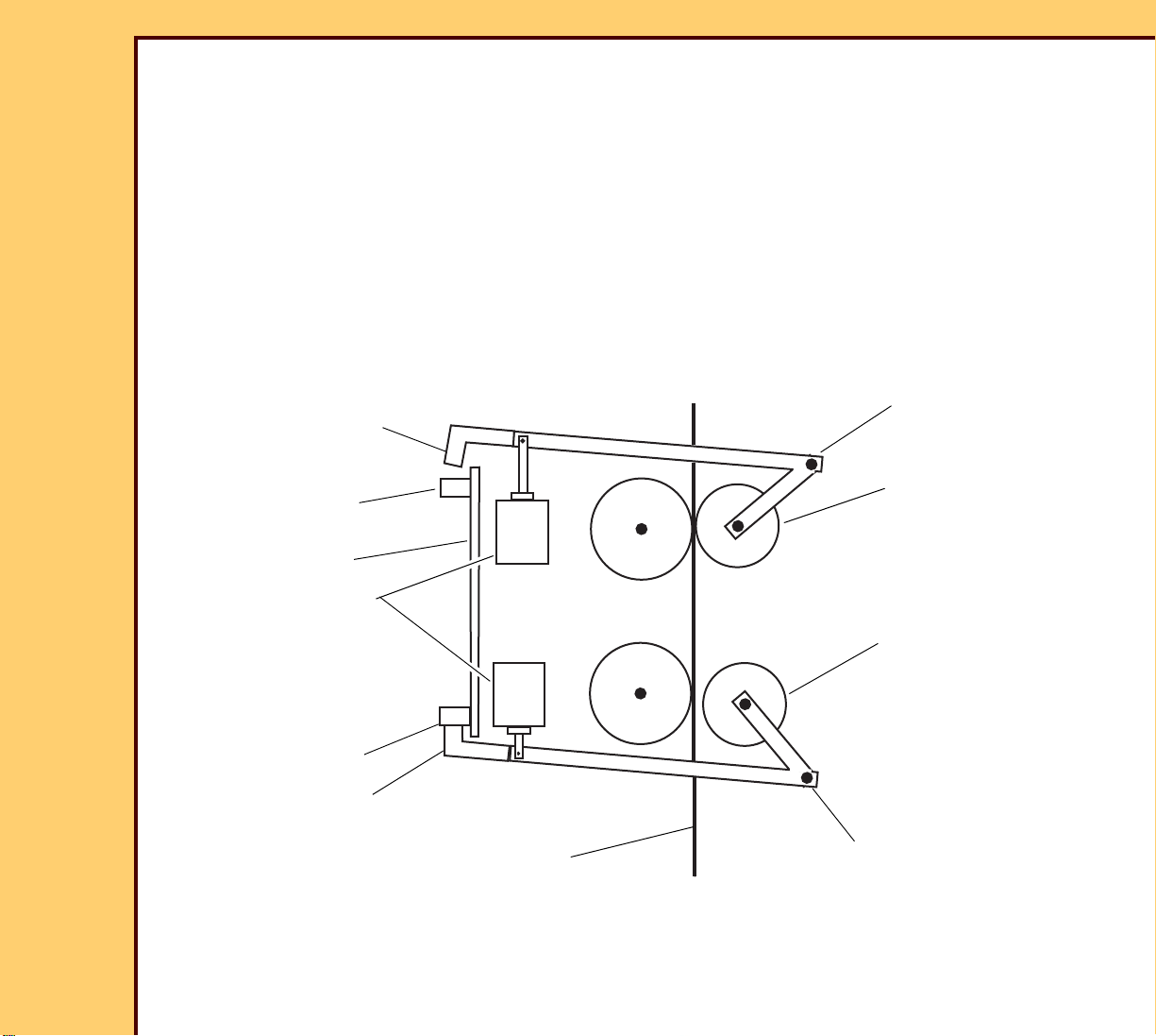
How It Works
Figure 21 is a simplified view of the ROLLERS that move film through the EXPOSURE
TRANSPORT. The 2 DRIVE ROLLERS are operated by the ROLLER DRIVE MOTOR, M12.
The MOTOR connects directly to the shaft of the EXIT DRIVE ROLLER. The ENTRANCE
DRIVE ROLLER is operated by a BELT and PULLEY from the EXIT DRIVE ROLLER.
Page 53

THEORY GUIDE EXPOSURE TRANSPORT AY
EXIT NIP
ROLLER
EXIT DRIVE
ROLLER
Laser Beam
ENTRANCE NIP
ROLLER
FILM-AT-ENTRANCE
FILM
ENTRANCE DRIVE
ROLLER
To PROCESSOR
From REGISTRATION AY
SOP BOARD
SENSOR
SENSOR, S12
FILM GUIDE
FILM GUIDE
30JUL07
8F2924
Page
53 of 72
Each DRIVE ROLLER has a companion NIP ROLLER that is opened and closed by a
LINEAR STEPPER MOTOR. Film is moved upward when a NIP ROLLER closes and holds
film against the adjacent DRIVE ROLLER. The speed of the SERVO MOTOR and opening
and closing of the 2 NIP ROLLERS is controlled by software on the EXPOSURE
TRANSPORT BOARD.
Figure 21
Page 54

THEORY GUIDE EXPOSURE TRANSPORT AY
30JUL07
8F2924
Page
54 of 72
The following sequence occurs when a film is moved through the EXPOSURE TRANSPORT.
1. Before film arrives, the NIP ROLLERS are pre-set:
- The ENTRANCE NIP ROLLER is moved to the closed position.
- The EXIT NIP ROLLER is moved to a partially closed position.
2. Film is moved up to the EXPOSURE TRANSPORT by the REGISTRATION AY.
3. Film leading edge “passes” the FILM-AT-ENTRANCE SENSOR, S12. This starts a
software timer.
4. Film enters the ENTRANCE ROLLERS.
5. NIP ROLLERS in the REGISTRATION AY open after FILM-AT-ENTRANCE signal. Film
motion is now controlled by the EXPOSURE TRANSPORT.
6. The ENTRANCE ROLLERS drive the film upward.
7. Film leading edge blocks the laser beam at the SOP SENSOR, S13.
The SOP signal does not affect the EXPOSURE TRANSPORT but it does start the
exposure process when film is in the EXPOSURE TRANSPORT.
8. The scanning laser beam starts to expose the film.
9. The EXIT NIP ROLLER starts to close - 1.25 seconds after film reaches the FILM-AT-
ENTRANCE SENSOR.
10.The ENTRANCE NIP ROLLER starts to open partly - 1.75 seconds after film reaches the
FILM-AT-ENTRANCE SENSOR.
11.The EXIT ROLLERS drive film for the remainder of the exposure.
12.Film enters the PROCESSOR.
Film development begins as exposure continues in the EXPOSURE TRANSPORT.
13.Film trailing edge “passes” the FILM-AT-ENTRANCE SENSOR, S12. This starts a software
timer.
14.The EXIT NIP starts to open - 3.0 seconds after the trailing edge “passes” the FILM-AT-
ENTRANCE SENSOR, S12
15. ENTRANCE and EXIT NIP ROLLERS are moved “home” (full-open) and then pre-set in
preparation for the next film.
Page 55

30JUL07
S15
3 PHASE
MOTOR
DRIVER
Feedback
SHAFT
ENCODER
EXPOSURE TRANSPORT
DRIVE MOTOR
MOTOR
DRIVER
MOTOR
DRIVER
ENTRANCE NIP
MOTOR
EXIT NIP
MOTOR
3 PHASE
DRIVE
BRIDGE
M12
M10
M11
MOTOR
CONTROL
ELECTRONICS
MICROPROCESSOR
RAM
MEMORY
256K x 16
EEPROM
MEMORY
64K
NVRAM
I2C Bus
EXIT ROLLER
SENSOR
ENTRANCE
ROLLER
SENSOR
FILM AT
ENTRANCE
SENSOR
EXPOSURE TRANSPORT BOARD
S14
S12
MCS Commands
Status
DSP and
CPLD
T
o/From
the PDB
8F2924
Page
55 of 72
THEORY GUIDE EXPOSURE TRANSPORT AY
EXPOSURE TRANSPORT CONTROL SYSTEM
The EXPOSURE TRANSPORT BOARD (ETB) controls the functions of the EXPOSURE
TRANSPORT. Figure 24 shows how the ETB connects to the external components it controls.
Figure 22
ETB - The ETB controls the speed of the EXPOSURE TRANSPORT DRIVE MOTOR, M12
and also controls the 2 linear STEPPER MOTORS, M10 and M11, that open and close the
ENTRANCE and EXIT NIP ROLLERS. Application software that runs in the
MICROPROCESSOR and in the DSP (DIGITAL SIGNAL PROCESSOR) provides the control
intelligence.
The MOTOR CONTROL ELECTRONICS has 2 complex microcircuits: a DSP and a CPLD
(COMPLEX PROGRAMMABLE LOGIC DEVICE). The DSP has a MICROPROCESSOR and
runs a part of the application software.
There are “testpoints” and LEDs on the ETB. Some of these are useful for trouble shooting.
See the FUNCTIONAL BLOCK DIAGRAMS for a description of the test points and LEDs.
Page 56
THEORY GUIDE EXPOSURE TRANSPORT AY
NIP ROLLER
MOTORS
EXIT NIP
ENTRANCE NIP
Pivot Point
Pivot Point
FLAG
FLAG
EXIT ROLLER
ENTRANCE ROLLER
ROLLER - open
ROLLER - closed
SENSOR, S14
SENSOR, S15
Film
ETB
30JUL07
8F2924
Page
56 of 72
EXPOSURE TRANSPORT DRIVE MOTOR and SHAFT ENCODER - This 3-phase SERVO
MOTOR is “powered” by a 3-phase AC voltage generated by the MOTOR CONTROL
ELECTRONICS. MOTOR speed is controlled by controlling the frequency of the AC MOTOR
voltage. When the MOTOR turns, the SHAFT ENCODER, mounted on the MOTOR SHAFT,
provides a stream of pulses, 2000 pulses per revolution. Feedback from the SHAFT
ENCODER is used in a closed loop control system to monitor and control the speed of the
SERVO MOTOR.
NIP ROLLER MOTORS - These 2 MOTORS are linear STEPPER MOTORS that open and
close the NIP ROLLERS. These MOTORS can move the NIP ROLLERS to the fully opened
“Home” position, the fully closed position or any position in between. Figure 23 shows a
simplified diagram of the mechanism that opens and closes the NIP ROLLERS
Figure 23 NIP ROLLER MECHANISM
FILM AT ENTRANCE SENSOR, S12 - This reflective SENSOR is located on the film guide at
the entrance to the EXPOSURE TRANSPORT BOARD. The SENSOR emits a light beam and
also has a detector to sense reflected light. The output of the SENSOR is high when no light
Page 57

THEORY GUIDE EXPOSURE TRANSPORT AY
30JUL07
8F2924
Page
57 of 72
is reflected back. When film enters the light path, light is reflected back to the SENSOR
causing the output to “go” low. The application software on the ETB uses the output of this
SENSOR to time the opening and closing of the NIP ROLLERS.
ENTRANCE ROLLER SENSOR, S14 - This SENSOR indicates when the ENTRANCE NIP
ROLLER is at the full open position. The SENSOR BODY is mounted on the ETB. When the
ENTRANCE NIP ROLLER is fully open. a flag on the NIP ROLLER mechanism blocks the
light beam in the SENSOR BODY, causing the output to change state.
EXIT ROLLER SENSOR, S15 - This SENSOR indicates when the EXIT NIP ROLLER is at
the full open position. The SENSOR BODY is located on the ETB and operates identically to
the ENTRANCE ROLLER SENSOR.
Page 58

30JUL07
8F2924
Page
58 of 72
THEORY GUIDE ISOLATION PLATE
Section 11: ISOLATION PLATE
To Be Supplied
Page 59

30JUL07
DRUM
FLATBED
COOLING
SECTION
PREVENTATIVE
MAINTENANCE
MODULE
FILM
PAT H
SLACK
LOOP
FROM
EXPOSURE
ROLLERS
TRANSPORT
8F2924
Page
59 of 72
THEORY GUIDE THERMAL PROCESSOR
Section 12: THERMAL PROCESSOR
Purpose
The purpose of the PROCESSOR is to:
• Develop the film image.
• Collect vapors (out-gasses) released when the film is heated.
This PROCESSOR is different from the PROCESSORS in all other DryView
IMAGERS. In this PROCESSOR film is developed in 2 stages. The DRUM first
rapidly heats the film to processing temperature. The film then moves into the
heated FLATBED AREA to complete the process. Most vapors are released after
the film is transported from the DRUM, which accounts for less FAZ on the DRUM
than in other DryView IMAGERS.
Figure 24 PROCESSOR - Side View
Page 60

THEORY GUIDE THERMAL PROCESSOR
30JUL07
8F2924
Page
60 of 72
Because film remains on the DRUM only to “pre-heat”, the DRUM moves faster
than in other DryView IMAGERS.
The PROCESSOR is on a DRAWER that pulls out. Using the SERVICE SWITCH,
service technicians can operate the PROCESSOR when it is extended.
Main Components
• SLACKLOOP AY- A set of 3 ROLLERS at the entrance to the PROCESSOR
that make a loop in the film to prevent tension in the film between the
PROCESSOR and the EXPOSURE TRANSPORT. The purpose is to prevent
the film from sending vibration from the DRUM back to the EXPOSURE
TRANSPORT.
• DRUM - Heats the film rapidly to processing temperature, 129° C ± 0.1° C.
• FLATBED - Keeps processing temperature, about 1° C less than the
temperature of the DRUM, to develop the image.
• COOLING SECTION - Removes heat from the film to stop image development
and harden the base.
• PREVENTIVE MAINTENANCE MODULE (PMM)- Captures and condenses
vapors released from the film when heated.
• PROCESSOR CONTROL BOARD (PCB) - This CIRCUIT BOARD has 2
MICROPROCESSORS and other ELECTRONICS that control HEATERS,
FANS and transport MOTORS in the PROCESSOR. Temperature “setpoints”
and other parameters are stored in NVRAM.
• PROCESSOR application software - Runs in the 2 MICROPROCESSORS on
the PCB to control HEATERS, cooling FANS and the 2 transport MOTORS in
the PROCESSOR.
Transport Within the PROCESSOR
Film is moved through the PROCESSOR by the rotating DRUM and ROLLERS in
the FLATBED and COOLING SECTION. A 24 V DC STEPPER MOTOR operates
the DRUM. A second 24 V DC STEPPER MOTOR operates the ROLLERS in the
FLATBED and COOLING SECTION. Both MOTORS connect to MOTOR DRIVERS
on the PCB. The speed of both MOTORS is controlled by the PROCESSOR
Page 61

THEORY GUIDE THERMAL PROCESSOR
30JUL07
8F2924
Page
61 of 72
CONTROL BOARD based on speed “setpoints” in NVRAM. Transport time through
the PROCESSOR is 22.5 seconds which is a throughput of 160 films per hour.
SLACKLOOP AY
The SLACKLOOP AY is a set of 3 ROLLERS before the entrance to the DRUM
that make a slight loop in the film. The loop is a “shock absorber” between the
EXPOSURE TRANSPORT and the PROCESSOR. It isolates the EXPOSURE
TRANSPORT from impact when the leading edge of the film contacts the DRUM
and it prevents the film from sending vibration from the PROCESSOR back to the
EXPOSURE TRANSPORT. The SLACKLOOP AY has no MOTORS or
ACTUATORS.
DRUM
The DRUM HAS 3 heat zones. Each zone includes a 120 V AC HEATER and a
RTD TEMPERATURE SENSOR. SLIP RINGS on the SHAFT of the DRUM provide
electrical connections to the PCB.
To control temperature of the DRUM, the PROCESSOR application software scans
the RTD SENSORS and switches 120 V AC power to the 3 HEATERS ON and
OFF to keep the temperature “setpoints” in NVRAM.
FLATBED
A DRIVE TRAIN sends power from the DRUM MOTOR to the DRUM.
A DRUM COVER provides access for cleaning the DRUM and clearing film jams.
The FLATBED is a covered area with HEATERS above and below the film path.
There are 8 heat zones with 8 RTD TEMPERATURE SENSORS. In the FLATBED
BASE below the film there are 9 HEATERS and 6 RTDs. Above the film, in the
FLATBED COVER, there are 2 HEATERS and 2 RTDs. For “over-temperature”
protection there are 3 THERMAL CUTOFF DEVICES in the FLATBED BASE and
2 in the COVER.
The PROCESSOR application software scans the RTD SENSORS and switches
120 V AC power to the 8 heat zones ON and OFF to keep processing
temperature. If a high temperature malfunction occurs, one of the THERMAL
Page 62

THEORY GUIDE THERMAL PROCESSOR
30JUL07
8F2924
Page
62 of 72
CUTOFFS in the FLATBED opens. This interrupts 120 V AC power to all
HEATERS in the FLATBED and DRUM.
COOLING SECTION
Film is cooled by contact with “hollow” ROLLERS in the COOLING SECTION. The
TEMPERATURE MICROPROCESSOR controls 2 FANS that blow cooling air
through the “hollow” ROLLERS to remove the heat. Temperature is controlled by
changing the speed of the 2 FANS.
PROCESSOR CONTROL BOARD
The PROCESSOR CONTROL BOARD (PCB) provides:
• Power and temperature control for the 3 HEATER zones on the DRUM.
• Power and temperature control for the 6 HEATER zones in the FLATBED
PLATE.
• Power and temperature control for the 2 HEATER zones in the FLATBED
COVER.
• Power and control for the 2 STEPPER MOTORS.
• Power and control for 2 COOLING FAN MOTORS.
• Power and control for 4 DC FAN MOTORS: the MAKEUP AIR FAN, the HEAT
EXCHANGER FAN, and 2 FILTER FANS.
• Power for a DC FAN that runs to cool the PROCESSOR CONTROL BOARD.
The PCB has 2 MICROPROCESSORS. The TEMPERATURE
MICROPROCESSOR controls the temperatures of the 11 heat zones and also
controls 6 FANS in the PROCESSOR. The main application software runs in this
MICROPROCESSOR. The software for the 2 TRANSPORT MOTORS is in the
MOTOR MICROPROCESSOR. Both MICROPROCESSORS are connected to the
I2C bus and to a shared NVRAM, also on the I2C bus. The
MICROPROCESSORS communicate with each other on the I2C bus and through
the shared NVRAM.
Each heat zone has a RESISTANCE TEMPERATURE DEVICE (RTD) and 1 or
more HEATER ELEMENTS “bonded” to an “aluminum substrate”. The RTD senses
Page 63

THEORY GUIDE THERMAL PROCESSOR
30JUL07
8F2924
Page
63 of 72
the temperature of the “aluminum base” by changing the electrical resistance. The
resistance is measured by switching a “known” current through the RTD and
measuring the voltage across it.
A MULTIPLEXER on the PCB connects the RTDs for the 11 heat zones to the
MICROPROCESSOR. Through the MULTIPLEXER, the MICROPROCESSOR
scans the RTD voltages. An ANALOG-TO-DIGITAL CONVERTER on the BOARD
converts each analog voltage to a digital temperature value. The application
software compares the temperature value for each zone with the temperature
“setpoint” for that zone, stored in NVRAM. The application then switches the
corresponding HEATERS ON or OFF in response to the differences between the
measured temperatures and temperature “setpoints”. SOLID STATE RELAYS
(SSRs) on the BOARD, controlled by the MICROPROCESSOR, switch 120 V AC
current to the HEATERS.
An additional RTD at the entrance of the DRUM senses a decrease in temperature
caused by heat transfer to the film during periods of high usage. In response, the
application software adjusts temperature “setpoints” for the DRUM upward to offset
for the heat loss.
Page 64

THEORY GUIDE THERMAL PROCESSOR
SOLID STATE RELAYS (SSRs)
SSR
CONTROL
LINES
COOLING
SECTION
FLATBED
DRUM and
SLIP RING
AY
Power to 8
HEATERS
Power to 3
HEATERS
Analog to
Digital Converter
Cooling
Zone RTD
Flatbed
RTDs (8)
DRUM
RTDs (3)
MULTIPLEXER
Analog
Voltage
(Temperature)
Digital
Voltage
(Temperature)
Scans RTDs
DRUM
STEPPER MOTOR
M13
MOTOR
DRIVER
FLATBED/
COOLING SECTION
STEPPER MOTOR
M14
MOTOR
DRIVER
NVRAM
Stores
Parameters
I2C Bus
COOLING SECTION
FAN PWM DRIVER
FAN ON/OFF
CONTROL
FAN
FAN
120 VAC Input
Power
MICROPROCESSOR
Temperature
MICROPROCESSOR
Transport
COOLING FANS
FAN
FAN
FAN
FAN
PROCESSOR CONTROL BOARD
I2C - To/From
DATAPATH BOARD
30JUL07
8F2924
Page
64 of 72
Figure 25 PROCESSOR CONTROL BOARD
The TEMPERATURE MICROPROCESSOR controls the HEATERS and 6 of the 7
FANS in the COOLING SECTION. See AIRFLOW in the PROCESSOR.
.
Page 65

THEORY GUIDE THERMAL PROCESSOR
30JUL07
8F2924
Page
65 of 72
The second MICROPROCESSOR controls the 2 transport MOTORS in the
PROCESSOR.
There are a number of LED INDICATORS on the BOARD that show the status of
the THERMAL CUTOUTS, status of HEATERS and a number of other conditions.
See the 6800 FUNCTIONAL DIAGRAMS for a description of the LEDs
AIRFLOW in the PROCESSOR
The graphic on Page 66 shows the 7 FANS that move air through the
PROCESSOR. All of these FANS, except the CIRCUIT BOARD FAN, are
controlled by the TEMPERATURE MICROPROCESSOR.
The 2 FILTER FANS and the MAKE-UP AIR FAN provide air flow through the
DRUM and FLATBED areas to remove vapors released when film is heated. The
vapors are condensed and collected in the PREVENTATIVE MAINTENANCE
MODULE (PMM). The FILTER FANS also pull air that has a low level of
processing vapors from the COOLING SECTION into the PMM. When the
IMAGER is in “Standby” mode, the MICROPROCESSOR turns these FANS OFF.
The HEAT EXCHANGE FAN blows cooling air through a HEAT EXCHANGER in
the PMM that cools the vapor stream. The vapor stream is cooled:
• To condense FAZ and other material.
• To increase the ability of the CHARCOAL in the PMM to “absorb” odors. The
ability of CHARCOAL to “absorb” odors decreases at high temperatures.
The HEAT EXCHANGE FAN is OFF when the IMAGER is in “Standby” mode.
The 2 COOLING FANS pull air through the “hollow” ROLLERS in the COOLING
SECTION. When the IMAGER is in “Full Run” mode, the PCB controls the speed
of these FANS in response to the RTD in the COOLING SECTION. In “Idle-ButReady” mode, these FANS run at low speed; in “Standby” mode the FANS are
OFF.
The CIRCUIT BOARD FAN provides cooling for the PCB. It runs at full speed in all
3 of the IMAGER power modes. It receives 24 V DC power from the PCB but is
not under software control.
Page 66

THEORY GUIDE THERMAL PROCESSOR
30JUL07
8F2924
Page
66 of 72
Figure 26 Air Flow and FANS
APPLICATION SOFTWARE
The PROCESSOR application software executes in the 2 MICROPROCESSORS on the PCB.
There are 2 separate applications. The primary application runs in the TEMPERATURE
MICROPROCESSOR. The second application runs in the TRANSPORT
MICROPROCESSOR. The software communicates with the MCS across the I2C network to
control the HEATERS and MOTORS. It also reports measurements and status back to the
Page 67

THEORY GUIDE THERMAL PROCESSOR
30JUL07
8F2924
Page
67 of 72
MCS. The 2 applications communicate with each other on the I2C network and through the
shared NVRAM on the PCB.
“Initialization”
At system Power-up or when the MCS sends Reset signal, the application does 2
“initialization” tests:
• NVRAM test
• Checksum verification of the MICROPROCESSOR application code.
“Initialization” is completed within 30 seconds.
Operation
During normal operation the primary application reads RTDs, computes
temperatures and switches 120 V AC HEATER power to the HEATERS when
necessary to keep “setpoint” temperatures within 1/2° C. This application also
controls film cooling. It reads the RTD in the COOLING SECTION and computes
FAN speeds to keep the “setpoint” temperature for the COOLING SECTION.
The MOTOR control application drives the 2 STEPPER MOTORS to transport film
through the PROCESSOR within 22.5 seconds.
Diagnostics
The application software checks for a number of “faults” within the PROCESSOR:
• Open RTD
• Short circuit in RTD
• Failed SOLID STATE RELAY
• Overheat condition
The application also starts diagnostic tests and a memory test when asked for
from the MCS. Test results are returned to the MCS.
Temperature Offsets
To be supplied
Page 68

30JUL07
TRANSFORMER
120 V AC CABLE
to DRE
FILTER
CAPACITOR
DC POWER
SUPPLY
IMAGER MAIN
POWER SWITCH
FAN
LINE MATCHING
PLUG
RELAYS
AC INPUT
RECEPTACLE and
EMI/RFI FILTER
8F2924
Page
68 of 72
THEORY GUIDE POWER MODULE
Section 13: POWER MODULE
The POWER MODULE supplies DC power to the CIRCUIT BOARDS in the MCS and 120volt AC power to the HEATERS in the PROCESSOR DRUM and FLATBED. It also supplies
120-volt AC power to the DRE.
Physical Layout
Page 69

30JUL07
IMAGER MAIN
POWER SWITCH
120 V AC CABLE
to DRE
LINE
PLUG
MATCHING
CIRCUIT
FRONT
DC POWER
BREAKERS
REAR
AC INPUT
RECEPTACLE and
EMI/RFI FILTER
SUPPLY
RELAYS
TRANSFORMER
PRIMARY
PCB
8F2924
Page
69 of 72
THEORY GUIDE POWER MODULE
Functions
The POWER MODULE:
• Supplies 5V and 24V DC power to the CIRCUIT BOARDS, MOTORS and SENSORS
• Supplies 120 V AC power to the PROCESSOR HEATERS
• Supplies 120 V AC power to the DRE
Page 70

THEORY GUIDE POWER MODULE
RELAY 1
DC POWER
SUPPLY
CIRCUIT
BREAKER
LINE
MATCHING
PLUG
POWER
TRANSFORMER
120
V AC
MAIN
CIRCUIT
PRIMARY
POWER
SWITCH
BREAKERS
PCB
120
V AC
120 V AC Power - to DRE
Voltage
Mismatch
Protection
AC Input
AC INPUT
+5 V DC
+24 V DC
+12V Wake-Up Signal - from DRE
+24V Interlock
Signal
120 V AC
RELAY 2
To PROCESSOR
HEATERS
To P O W E R
DISTRIBUTION
BOARD
120 V AC Test Point
SECONDARY
PCB
RELAY
From POWE R
DISTRIBUTION
BOARD
Transformer Output
Sample
30JUL07
8F2924
Page
70 of 72
The following block diagram shows the main components in the POWER MODULE. Refer to
the 6800 FUNCTIONAL DIAGRAMS for a circuit diagram.
The POWER MODULE can be set up for any 1 of 5 input voltage ranges:
• 90 -105 V AC
• 106 - 130 V AC
• 180 - 210 V AC
• 211 - 230 V AC
• 231 - 250 V AC
A LINE MATCHING PLUG configures the primary windings of the transformer so that the
secondary voltage is always approximately 120 V AC. Five LINE MATCHING plugs are
supplied with the IMAGER, 1 for each of the possible input voltage ranges. The appropriate
LINE MATCHING PLUG is inserted when the IMAGER is installed.
The TRANSFORMER supplies 120 V AC power to the DC POWER SUPPLY, the
PROCESSOR HEATERS and the DRE. During normal operation, both RELAY 1 and RELAY
2 are energized to enable the 120 V AC outputs to the DC POWER SUPPLY and
PROCESSOR HEATERS.
Page 71

THEORY GUIDE POWER MODULE
30JUL07
8F2924
Page
71 of 72
• A 12 V DC “Wake-up” signal from the DRE energizes RELAY 1 when the IMAGER is in
the Ready state. If the IMAGER enters “sleep mode” or “Power Off” mode, the “Wake-up”
signal goes low and RELAY 1 opens to interrupt 120 V AC power to the HEATERS and to
the DC POWER SUPPLY.
• A 24 V DC interlock signal from the MCS electronics energizes RELAY 2 during normal
operation. If an open door or other interlock condition causes the interlock signal to drop
out, RELAY 2 is de-energized and interrupts 120 V AC power to the HEATERS. For a
description of the interlock conditions, see INTERLOCK SYSTEM.
120 V AC power to the DRE is never interrupted unless the MAIN POWER SWITCH on the
POWER MODULE is opened or a fault condition interrupts input power to the POWER
MODULE.
Fault Protection in the POWER MODULE
The POWER MODULE contains two 15 amp circuit breakers at the AC input and one 15 amp
circuit breaker at the 120 V AC output of the transformer. There are also 2 THERMAL
SWITCHES in the transformer that open if the transformer overheats. The THERMAL
SWITCHES reset automatically when the transformer cools.
The PRIMARY PCB protects against an incorrect LINE MATCHING PLUG. If the LINE
MATCHING PLUG is not correct for the AC input voltage, the TRANSFORMER secondary
voltage will not be correct (120 V AC). Circuitry on the PRIMARY PCB monitors a sampling
winding on the secondary side of the transformer and energizes a RELAY on the PCB when
the secondary voltage is correct. If the secondary voltage is not correct, the RELAY opens to
interrupt the AC input path to the transformer.
The POWER MODULE also contains surge suppression circuitry.
Page 72

30JUL07
8F2924
Page
72 of 72
THEORY GUIDE Publication History
Section 14: Publication History
Publication
Date
Publication
No.
ECO No.
Changed
Pages
File Name Notes
30JUL07 8F2924 CN0008638 -- 8f2920.fm • New Publication
• Rev A
Printed in U.S.A. • 6800_Theory_8f2924.fm
Carestream Health, Inc.
150 Verona Street
Rochester, NY 14608
DryView is a trademark of Carestream Health.
Kodak is a trademark of Kodak used under license.
 Loading...