

Page 1
© EASTMAN KODAK COMPANY, 2005 HEALTH GROUP
Confidential
Restricted
Information
{Adjust/Replace}{Production}{Health Group}{ExternalAndInternal}
ADJUSTMENTS AND REPLACEMENTS
for the
Kodak DirectView CR 825/850 SYSTEMS
Service Codes: 5634, 4825
Important
Qualified service personnel must do these procedures.
Publication No. AR4825-1
10DEC05
Supersedes AR4825-1
21JUL04
H177_0500AC
Page 2

ADJUSTMENTS AND REPLACEMENTS
10DEC05
AR4825-1
Page
2 of 160
PLEASE NOTE The information contained herein is based on the experience and knowledge relating to the
subject matter gained by Eastman Kodak Company prior to publication.
No patent license is granted by this information.
Eastman Kodak Company reserves the right to change this information without notice, and
makes no warranty, express or implied, with respect to this information. Kodak shall not be
liable for any loss or damage, including consequential or special damages, resulting from any
use of this information, even if loss or damage is caused by Kodak’s negligence or other fault.
This equipment includes parts and assemblies sensitive to damage from electrostatic
discharge. Use caution to prevent damage during all service procedures.
Table of Contents
Description Page
Adjustments. . . . . . . . . . . . . . . . . . . . . . . . . . . . . . . . . . . . . . . . . . . . . . . . . . . . . . . . . . . 4
INTERLOCK SWITCH . . . . . . . . . . . . . . . . . . . . . . . . . . . . . . . . . . . . . . . . . . . . . . . 4
TOP COVER. . . . . . . . . . . . . . . . . . . . . . . . . . . . . . . . . . . . . . . . . . . . . . . . . . . . . . . 6
GALVO BOARD . . . . . . . . . . . . . . . . . . . . . . . . . . . . . . . . . . . . . . . . . . . . . . . . . . . . 8
GALVO ROTATION . . . . . . . . . . . . . . . . . . . . . . . . . . . . . . . . . . . . . . . . . . . . . . . . . 18
FOLD MIRROR . . . . . . . . . . . . . . . . . . . . . . . . . . . . . . . . . . . . . . . . . . . . . . . . . . . . . 24
COLLECTOR AY . . . . . . . . . . . . . . . . . . . . . . . . . . . . . . . . . . . . . . . . . . . . . . . . . . . 33
INTERMEDIATE PLATE . . . . . . . . . . . . . . . . . . . . . . . . . . . . . . . . . . . . . . . . . . . . . 37
CAM SENSOR BOARD A8 . . . . . . . . . . . . . . . . . . . . . . . . . . . . . . . . . . . . . . . . . . 41
CAM MOTOR AY . . . . . . . . . . . . . . . . . . . . . . . . . . . . . . . . . . . . . . . . . . . . . . . . . . 44
SLED CAM FOLLOWER . . . . . . . . . . . . . . . . . . . . . . . . . . . . . . . . . . . . . . . . . . . . 47
CLAMP BAR. . . . . . . . . . . . . . . . . . . . . . . . . . . . . . . . . . . . . . . . . . . . . . . . . . . . . . . 52
CASSETTE END STOP . . . . . . . . . . . . . . . . . . . . . . . . . . . . . . . . . . . . . . . . . . . . . 56
REAR CASSETTE SENSOR . . . . . . . . . . . . . . . . . . . . . . . . . . . . . . . . . . . . . . . . . . 58
EXTRACTION BAR HOME POSITION . . . . . . . . . . . . . . . . . . . . . . . . . . . . . . . . . 61
PLATE POSITIONING AY . . . . . . . . . . . . . . . . . . . . . . . . . . . . . . . . . . . . . . . . . . . 66
RIGHT and LEFT PLUSH AY - Alignment . . . . . . . . . . . . . . . . . . . . . . . . . . . . . . 73
LEFT PLUSH AY - Vertical Position . . . . . . . . . . . . . . . . . . . . . . . . . . . . . . . . . . . 77
INTERNAL BAR CODE READER . . . . . . . . . . . . . . . . . . . . . . . . . . . . . . . . . . . . . . 81
CASSETTE LOAD CRADLE . . . . . . . . . . . . . . . . . . . . . . . . . . . . . . . . . . . . . . . . . 86
Replacements . . . . . . . . . . . . . . . . . . . . . . . . . . . . . . . . . . . . . . . . . . . . . . . . . . . . . . . . . 88
GALVO and BLOCK AY . . . . . . . . . . . . . . . . . . . . . . . . . . . . . . . . . . . . . . . . . . . . . 88
OPTICS MODULE . . . . . . . . . . . . . . . . . . . . . . . . . . . . . . . . . . . . . . . . . . . . . . . . . . 90
PMT/DAS BOARD . . . . . . . . . . . . . . . . . . . . . . . . . . . . . . . . . . . . . . . . . . . . . . . . . . 92
PMTs and COLLECTOR AY . . . . . . . . . . . . . . . . . . . . . . . . . . . . . . . . . . . . . . . . . . 94
Page 3

ADJUSTMENTS AND REPLACEMENTS
10DEC05
AR4825-1
Page
3 of 160
FOLD MIRROR . . . . . . . . . . . . . . . . . . . . . . . . . . . . . . . . . . . . . . . . . . . . . . . . . . . . . 96
CASSETTE HANDLING AY . . . . . . . . . . . . . . . . . . . . . . . . . . . . . . . . . . . . . . . . . . 97
CAM MOTOR AY . . . . . . . . . . . . . . . . . . . . . . . . . . . . . . . . . . . . . . . . . . . . . . . . . . . 101
HOOK YOKE AY and HOOK YOKE BEARING. . . . . . . . . . . . . . . . . . . . . . . . . . . 103
IDLER ROLLER AY . . . . . . . . . . . . . . . . . . . . . . . . . . . . . . . . . . . . . . . . . . . . . . . . . 104
CASSETTE DRIVE AY . . . . . . . . . . . . . . . . . . . . . . . . . . . . . . . . . . . . . . . . . . . . . . 107
CASSETTE DRIVE ROLLERS . . . . . . . . . . . . . . . . . . . . . . . . . . . . . . . . . . . . . . . . 109
CASSETTE DRIVE MOTOR AY . . . . . . . . . . . . . . . . . . . . . . . . . . . . . . . . . . . . . . . 111
LEFT PLUSH AY . . . . . . . . . . . . . . . . . . . . . . . . . . . . . . . . . . . . . . . . . . . . . . . . . . . 112
RIGHT PLUSH AY . . . . . . . . . . . . . . . . . . . . . . . . . . . . . . . . . . . . . . . . . . . . . . . . . . 114
EXTRACTION BAR . . . . . . . . . . . . . . . . . . . . . . . . . . . . . . . . . . . . . . . . . . . . . . . . . 116
SLOW SCAN AY . . . . . . . . . . . . . . . . . . . . . . . . . . . . . . . . . . . . . . . . . . . . . . . . . . . 117
EXTRACTION BAR REFERENCE SENSOR S9 . . . . . . . . . . . . . . . . . . . . . . . . . . 119
PLATE PRESENT SENSOR S5 . . . . . . . . . . . . . . . . . . . . . . . . . . . . . . . . . . . . . . . 120
COIL BOARD A7, ENCODER and SLOW SCAN ROTOR . . . . . . . . . . . . . . . . . . 122
PLATE POSITIONING AY . . . . . . . . . . . . . . . . . . . . . . . . . . . . . . . . . . . . . . . . . . . . 126
ERASE LAMP AY . . . . . . . . . . . . . . . . . . . . . . . . . . . . . . . . . . . . . . . . . . . . . . . . . . 127
CPU. . . . . . . . . . . . . . . . . . . . . . . . . . . . . . . . . . . . . . . . . . . . . . . . . . . . . . . . . . . . . . 129
HARD DRIVE . . . . . . . . . . . . . . . . . . . . . . . . . . . . . . . . . . . . . . . . . . . . . . . . . . . . . . 132
Additional Service Procedures . . . . . . . . . . . . . . . . . . . . . . . . . . . . . . . . . . . . . . . . . . . 139
Opening and Removing COVERS and PANELS . . . . . . . . . . . . . . . . . . . . . . . . . 139
Restoring the Purchased Options. . . . . . . . . . . . . . . . . . . . . . . . . . . . . . . . . . . . . 143
Restoring the Configuration . . . . . . . . . . . . . . . . . . . . . . . . . . . . . . . . . . . . . . . . . 144
Setting the Laser Calibration Voltage. . . . . . . . . . . . . . . . . . . . . . . . . . . . . . . . . . 144
Calibration for the CR 825/850 SYSTEM . . . . . . . . . . . . . . . . . . . . . . . . . . . . . . . 145
Page 4
10DEC05
AR4825-1
Page
4 of 160
ADJUSTMENTS AND REPLACEMENTS Adjustments
Section 1: Adjustments
INTERLOCK SWITCH
Adjustment Specification
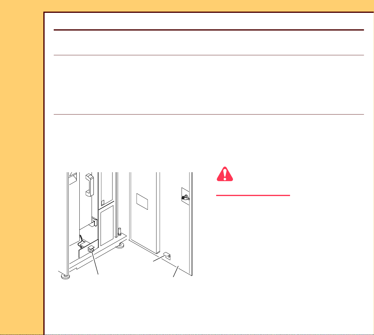
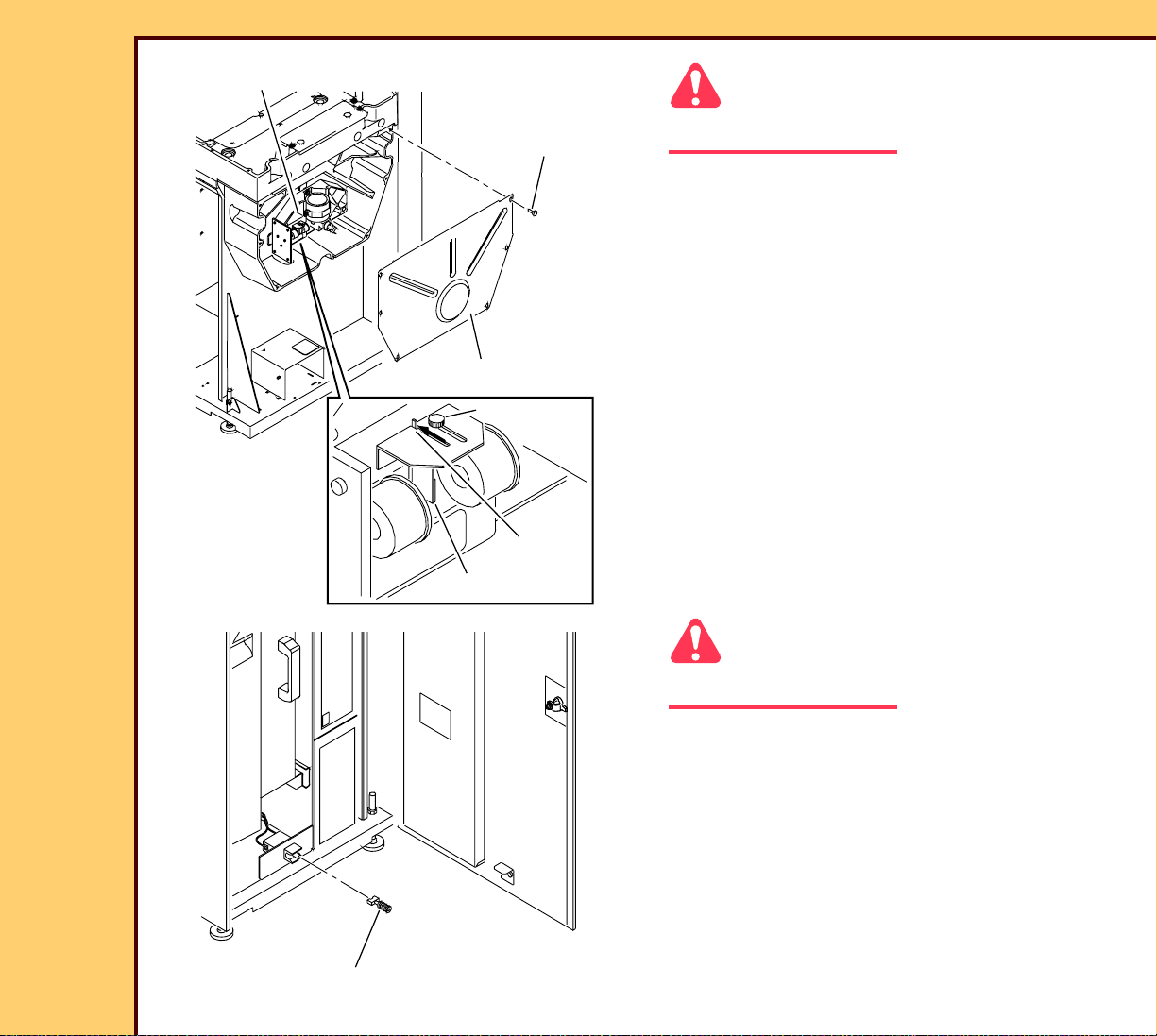
Purpose: To place the INTERLOCK ACTUATOR in the correct position.
Specification: The INTERLOCK ACTUATOR enters the center of the INTERLOCK
SWITCH when you close the FRONT DOOR.
Special Tools: None
Prerequisites:
None
To Check:
Caution
Dangerous Voltage
INTERLOCK
SWITCH
INTERLOCK
ACTUATOR
FRONT DOOR
H194_0043ACA
H194_0043AC
1 Open the FRONT DOOR.
2 Close the FRONT DOOR and observe
the INTERLOCK ACTUATOR entering
the INTERLOCK SWITCH.
3 Check that the INTERLOCK
ACTUATOR enters the center of the
INTERLOCK SWITCH.
Page 5
ADJUSTMENTS AND REPLACEMENTS Adjustments
10DEC05
AR4825-1
Page
5 of 160
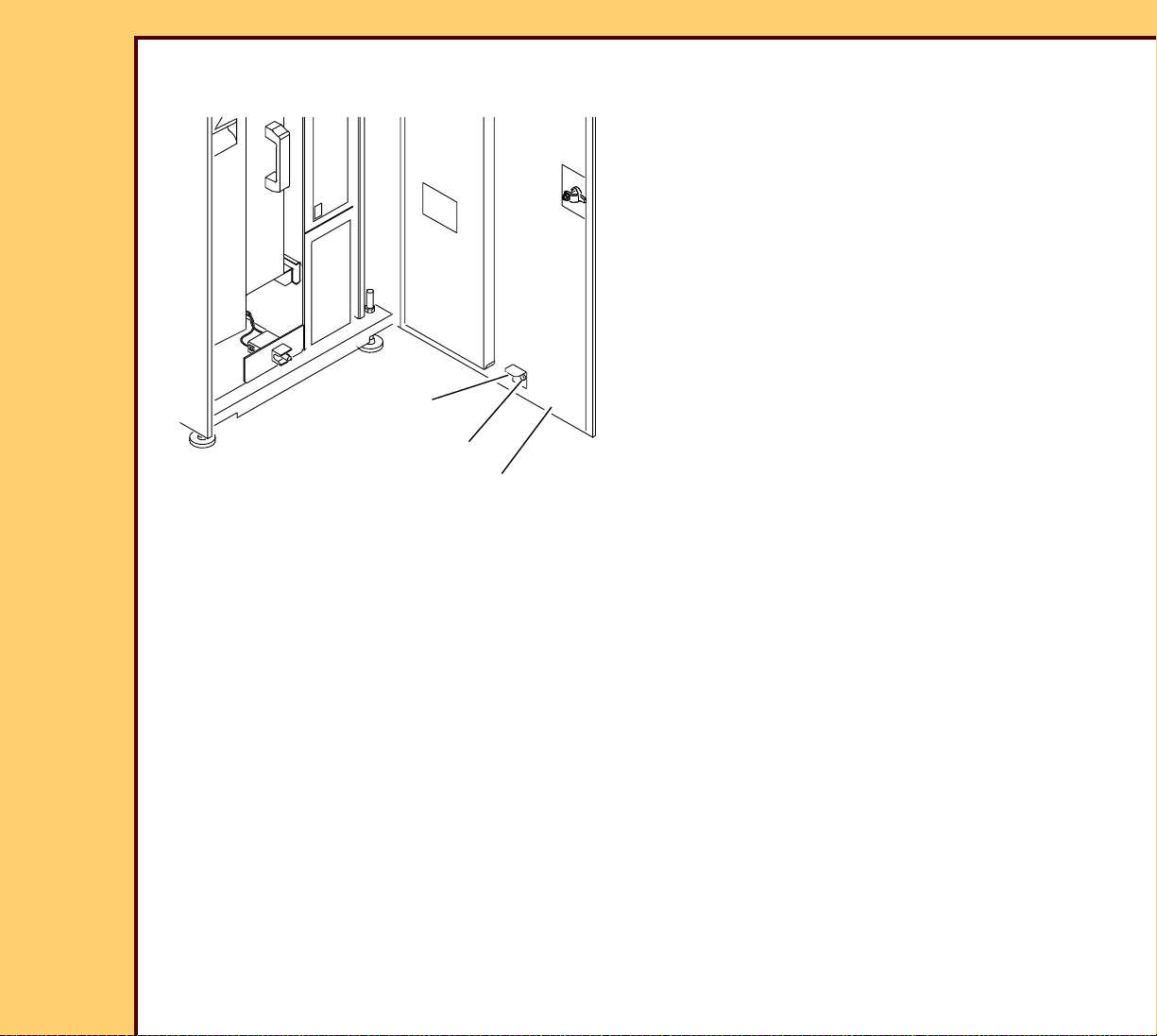
To Ad j u st :
INTERLOCK
ACTUATOR
Postrequisites:
2 SCREWS
FRONT DOOR
H194_0043ACB
H194_0043AC
1 Open the FRONT DOOR.
2 Loosen the 2 SCREWS.
3 Move the INTERLOCK ACTUATOR up
or down to the correct position.
4 Tighten the 2 SCREWS.
None
Page 6

10DEC05
AR4825-1
Page
6 of 160
ADJUSTMENTS AND REPLACEMENTS Adjustments
TOP COVER
Adjustment Specification
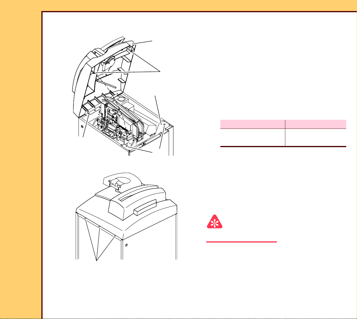
Purpose: To place the TOP COVER in the correct position.
Specification: When the TOP COVER is closed, the 2 PINS seat into the center of the
holes in the CROSSBRACE.
Special Tools: None
Prerequisites:
1 Adjust the INTERLOCK SWITCH.
To Check:
1 Open the FRONT DOOR.
TOP COVER
2 PINS
2 Open the TOP COVER.
3 Close the TOP COVER slowly and
observe the 2 PINS entering the holes
in the CROSSBRACE.
H194_0044ACA
H194_0044AC
CROSSBRACE
holes
4 Check that the 2 PINS seat into the
center of the holes in the
CROSSBRACE.
Page 7
ADJUSTMENTS AND REPLACEMENTS Adjustments
10DEC05
AR4825-1
Page
7 of 160
To Ad j u st :
5 LOWER SCREWS
H194_0044ACB
H194_0044AC
TOP COVER
2 PINS
CROSSBRACE
holes
1 Open the TOP COVER.
2 Loosen the 5 LOWER SCREWS until
the TOP COVER can be moved with a
small force.
3 Close the TOP COVER.
4 Move the TOP COVER left or right until
the 2 PINS seat into the center of the
holes of the CROSSBRACE.
5 Can you make the adjustment?
No Yes
Continue with
Step 6.
Advance to
Step 10.
6 Remove the REAR PANEL.
7 Loosen the 3 SCREWS.
8 Move the TOP COVER left or right until
the 2 PINS seat into the center of the
holes of the CROSSBRACE.
3 SCREWS
Postrequisites:
None
H194_0051ACA
H194_0051AC
9 Tighten the 3 SCREWS.
Important
Do not move the TOP COVER left or right
10 Carefully lift the TOP COVER.
11 Tighten the 5 LOWER SCREWS.
Page 8
10DEC05
AR4825-1
Page
8 of 160
ADJUSTMENTS AND REPLACEMENTS Adjustments
GALVO BOARD
Adjustment Specification
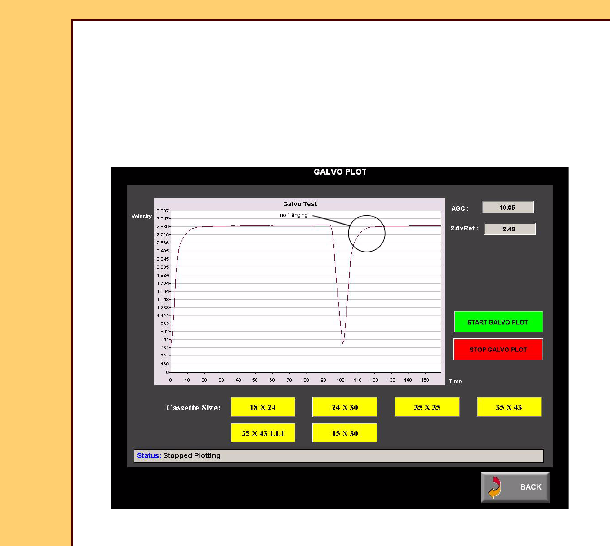
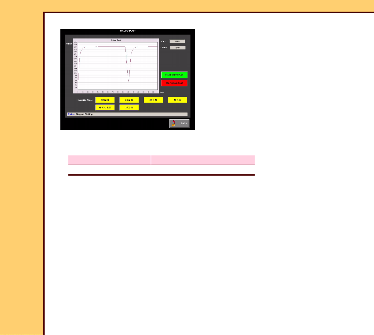
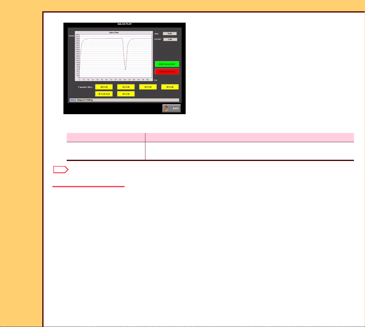
Purpose: To set the AUTOMATIC GAIN CONTROL (AGC), and the “Velocity Profile”.
Specification: • The AGC voltage on the “Galvo Plot” screen is 8.2 V DC - 11.9 V DC
with the correct “Velocity Profile”.
• No “Ringin g” in the “Wave Form”.
Special Tools: • TOOL TL-5726
• DIGITAL VOLTAGE METER (DVM) TL-3386
Prerequisites:
1 Do Setting the Laser Calibration Voltage.
To Check:
Caution
Dangerous Voltage
1 Energize the system.
Important
You must have a “Session ID” for access to “Service Functions” and “Diagnostics”. See
SERVICE BULLETIN 843.
Page 9
ADJUSTMENTS AND REPLACEMENTS Adjustments
10DEC05
AR4825-1
Page
9 of 160
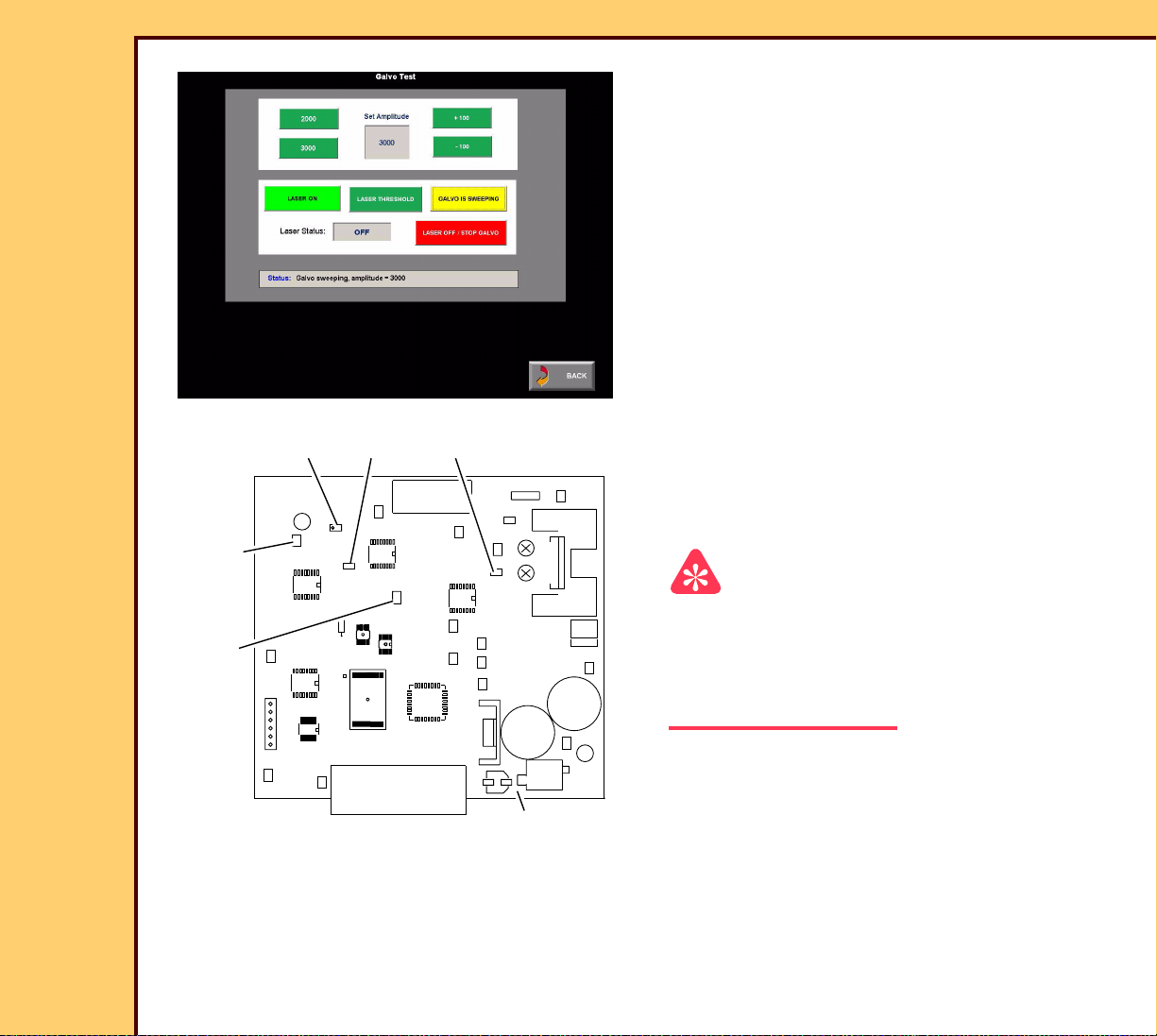
2 At the main menu, touch:
• [Ser vice Functions]
• [Diagnostics]
• [Galvo Plot]
• [Star t Galvo Plot]
• [35 x 43]
Correct
Page 10
ADJUSTMENTS AND REPLACEMENTS Adjustments
10DEC05
AR4825-1
Page
10 of 160
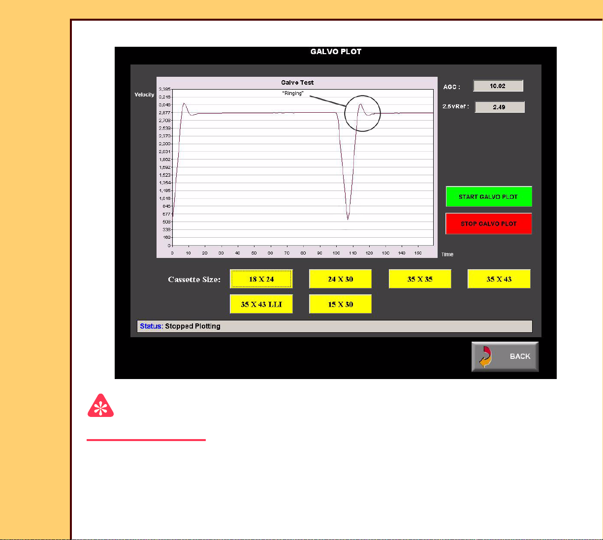
Not Correct
Important
The GALVO stops after 500 cycles. If necessary to start again, select “Star t Galvo Plot”.
3 Check:
• no “Ringing” in the “Wave Form”
• “AGC” is at 8.2 V DC - 11.9 V DC
Page 11
ADJUSTMENTS AND REPLACEMENTS Adjustments
10DEC05
AR4825-1
Page
11 of 160
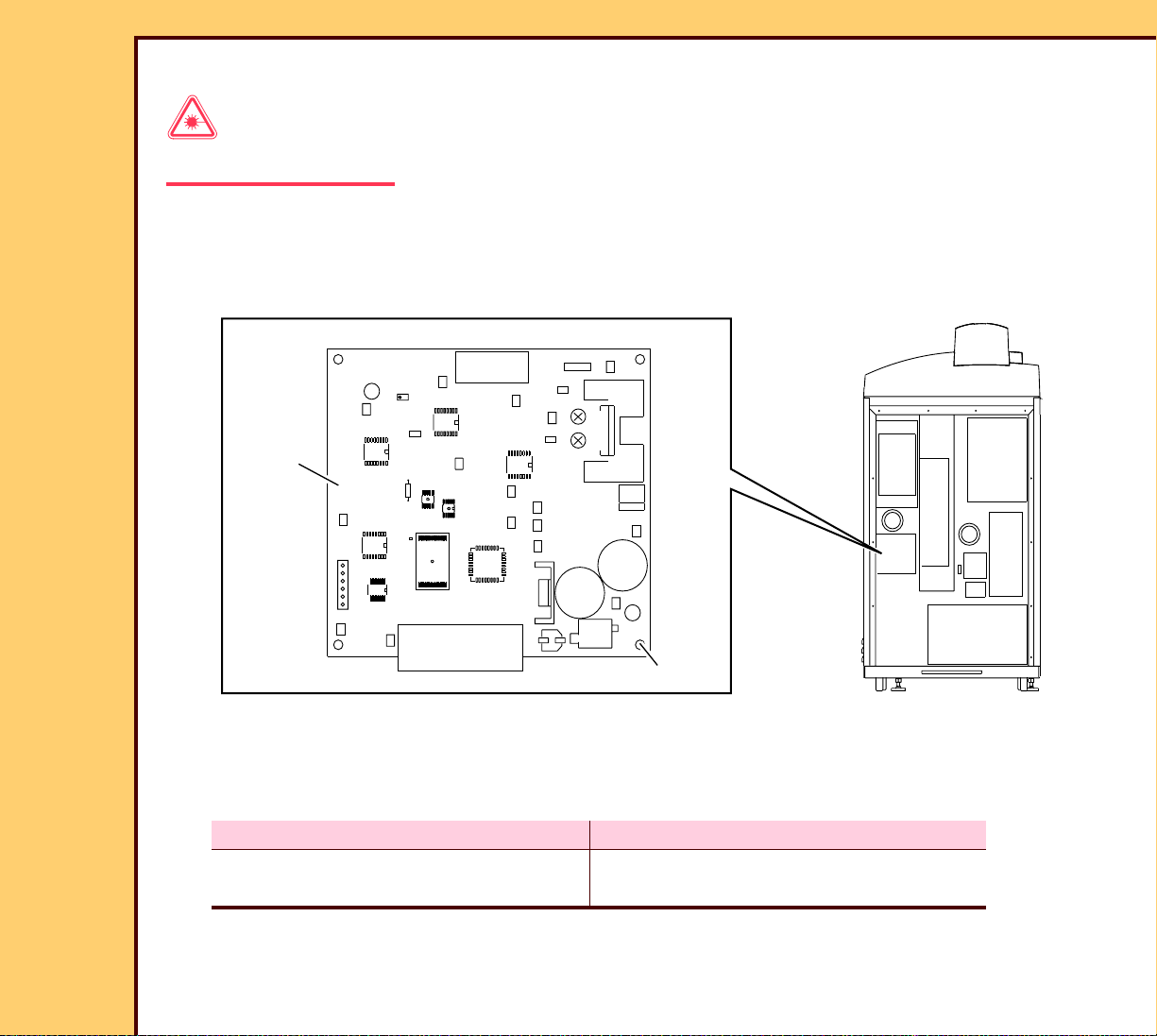
To Ad j u st :
Laser Warning
This equipment uses a visible red laser. Prevent direct exposure to the beam from the laser.
1 Do Step 1 - Step 8 of the GALVO ROTATION procedure.
2 Remove the REAR PANEL.
TP7
R112
TP6
TP3
GALVO
BOARD
TP10
R112
TP1
R2
TP13
C55
TP17
61
TP2
TP16
TP4
TP11 R1
TP14
TP9
TP15
TP12
TP5
H194_1408BCB
H194_1408BC
4 SCREWS
3 On the GALVO BOARD, use the DVM TL-3386 set to V DC and connect the (+) end of
the DVM to TP13 and the (-) end of the DVM to TP1.
4 Is the GALVO BOARD new?
Yes No
Adjust R2 until the voltage on the
DVM is 10 ± 0.02 V DC.
Check that the voltage on the DVM is
between 8.2 V DC and 11.9 V DC.
Page 12

ADJUSTMENTS AND REPLACEMENTS Adjustments
10DEC05
AR4825-1
Page
12 of 160
5 Touch:
• [Star t Galvo Plot]
• [35 x 43]
6 Adjust R1 until the “hook” or “ringing” is just visible on the GALVO SWEEP PROFILE.
7 Adjust R1 until the “hook” or “ringing” just disappears on the GALVO SWEEP PROFILE.
8 Touch:
• [Back]
• [Galvo Test]
• [Star t Galvo Plot]
• [35 x 43]
9 Is the “Wave Form” correct?
Yes No
Advance to Step 16. Continue with Step 10.
10 Touch:
• [Back]
• [Galvo Test]
• [Star t Galvo]
Page 13
10DEC05
AR4825-1
Page
13 of 160
ADJUSTMENTS AND REPLACEMENTS Adjustments
11 Set the “Amplitude” to “3000”.
TP1
TP13
H194_0045ACA
H194_0045AC
R112
TP1
TP17
16
TP2
TP16
R2
R1
12 Use the DVM TL-3386 set to V AC and
connect the (+) end of the DVM to
TP10
R112
R2
TP13
C55
TP4
R1TP11
TP14
TP9
TP15
TP12
TP5
TP7
R112
TP6
TP13 and the (-) end of the DVM to
TP1.
Important
• The GALVO must be “sweeping” when
you adjust R112.
• The lowest value is normally 10 - 25 mV
AC.
TP3
13 Adjust R112 until the voltage on the
DVM is at the lowest value.
GALVO BOARD
Page 14
10DEC05
AR4825-1
Page
14 of 160
ADJUSTMENTS AND REPLACEMENTS Adjustments
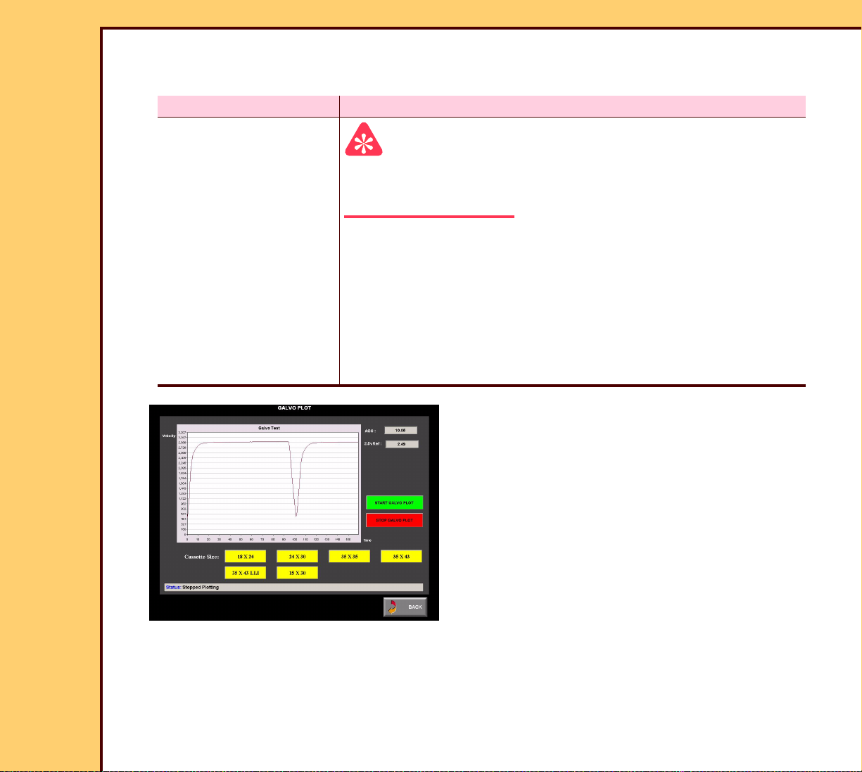
14 Touch:
• [Stop Galvo]
• [Back]
• [Galvo Plot]
• [Star t Galvo Plot]
• [35 x 43]
15 Is the “Wave Form” correct?
Yes No
Continue with Step 16.Do Step 3 - Step 15 again.
Page 15
10DEC05
AR4825-1
Page
15 of 160
ADJUSTMENTS AND REPLACEMENTS Adjustments
PMT COVER
5 SCREWS
TOOL TL-5726
3.17 mm
(0.125 in.)
laser beam
2 BEAM
CLIPPERS
n
e
h
w
.
n
d
e
io
t
t
a
ia
e
d
f
a
e
.
r
d
r
m
s
e
a
k
s
e
c
a
b
L
lo
o
r
t
e
B
t
e
3
r
in
s
u
s
d
s
a
n
o
l
a
p
C
x
n
e
e
p
id
o
o
v
A
GALVO
FOLD
MIRROR
COVER
H194_1418HCA
H194_1418HC
16 Lift the TOP COVER.
17 Remove:
• 5 SCREWS
• PMT COVER
• FOLD MIRROR COVER
• 6 SCREWS
• COVER
18 Install the TOOL TL-5726.
SCREW
6 SCREWS
COVER
Page 16
ADJUSTMENTS AND REPLACEMENTS Adjustments
10DEC05
AR4825-1
Page
16 of 160
19 Touch [Laser On].
20 Is the laser beam 3.17 mm (.125 in.) on the 2 BEAM CLIPPERS?
Yes No
Continue with
Step 21.
Important
• Rotating the GALVO centers the laser beam.
• Adjusting R2 makes the laser beam shor ter or longer.
a. Loosen the SCREW.
b. Rotate the GALVO until the laser beam is in the center.
c. Tighten the SCREW.
d. Adjust R2 on the GALVO BOARD until the laser beam is
3.17 mm (.125 in.) on the 2 BEAM CLIPPERS.
e. Continue with Step 21.
21 Touch:
• [Stop Galvo]
• [Back]
• [Galvo Plot]
• [Star t Galvo Plot]
22 Check that the “Velocity Profile” is
correct for all sizes of CASSETTE.
Page 17

ADJUSTMENTS AND REPLACEMENTS Adjustments
10DEC05
AR4825-1
Page
17 of 160
23 Is the “Velocity Profile” correct?
Yes No
Continue with
Step 25.
a. Adjust R1 until the “Velocity Profile” is
correct.
b. Do Step 19 - Step 23, or use
diagnostics to solve the problem.
24 Do GALVO ROTATION.
25 Install:
• REAR PANEL
• FOLD MIRROR COVER
• PMT COVER
• 5 SCREWS
• COVER
• 6 SCREWS
Postrequisites:
1 Adjust the FOLD MIRROR.
Page 18
10DEC05
AR4825-1
Page
18 of 160
ADJUSTMENTS AND REPLACEMENTS Adjustments
GALVO ROTATION
Adjustment Specification
Purpose: To set the GALVO home position.
Specification: The laser beam displays on the wide RING of the F-THETA LENS.
Special Tools: None
Prerequisites:
1 Do Setting the Laser Calibration Voltage.
2 Adjust the GALVO BOARD.
To Check:
Press the Escape key to dismiss the video after viewing.
Laser Warning
• This equipment uses a visible red laser. Prevent direct exposure to the beam from the
laser.
• Dangerous Voltage
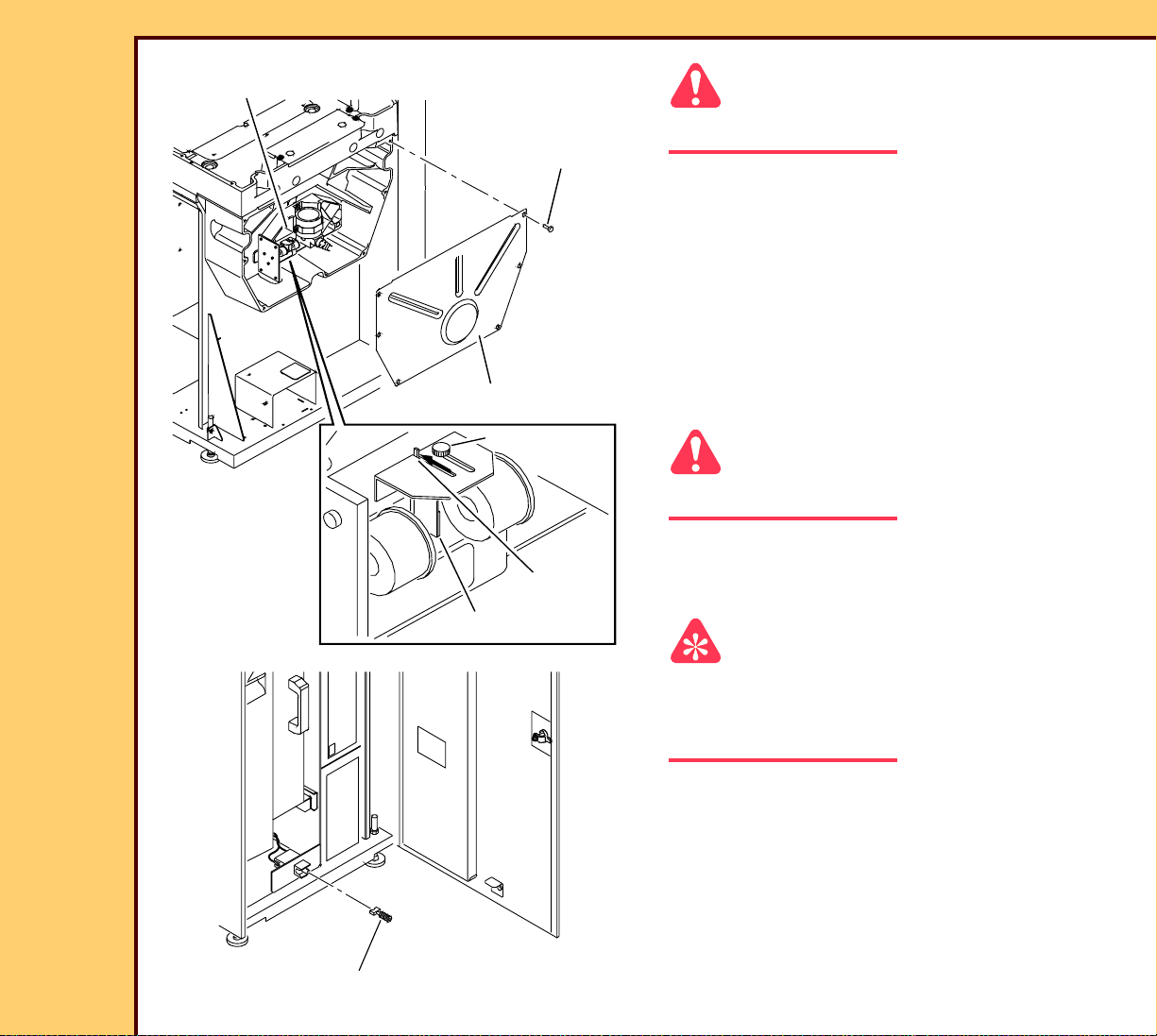
1 De-energize the system.
2 Remove the FRONT DOOR and RIGHT PANEL.
Page 19
10DEC05
AR4825-1
Page
19 of 160
ADJUSTMENTS AND REPLACEMENTS Adjustments
OPTICAL AY
Caution
Do not cause damage to the OPTICAL AY.
6 SCREWS
3 Remove:
• 6 SCREWS
hen
.
ted
tion w
dia
efea
m.
s d
ea
ck
aser ra
b
L
rlo
to
te
3B
re
d in
posu
an
Class
pen
id ex
o
vo
A
• COVER
4 Loosen the THUMBSCREW.
5 Move the LASER FILTER into the
service position.
H194_1412GCA
H194_1412GC
Class 3B
open and interlocks defeated.
void exposure to beam
A
INTERLOCK KEY
Laser radiation w
COVER
THUMBSCREW
hen
.
service
position
LASER FILTER
H194_0049ACA
H194_0049AC
6 Tighten the THUMBSCREW.
Caution
Dangerous Voltage
7 Energize the system.
8 Install the INTERLOCK KEY.
Important
You must have a “Session ID” for access to
“Service Functions” and “Diagnostics”. See
SERVICE BULLETIN 843.
9 At the main menu, touch:
• [Ser vice Functions]
• [Diagnostics]
• [Galvo Test]
• [Laser on]
Page 20
10DEC05
AR4825-1
Page
20 of 160
ADJUSTMENTS AND REPLACEMENTS Adjustments
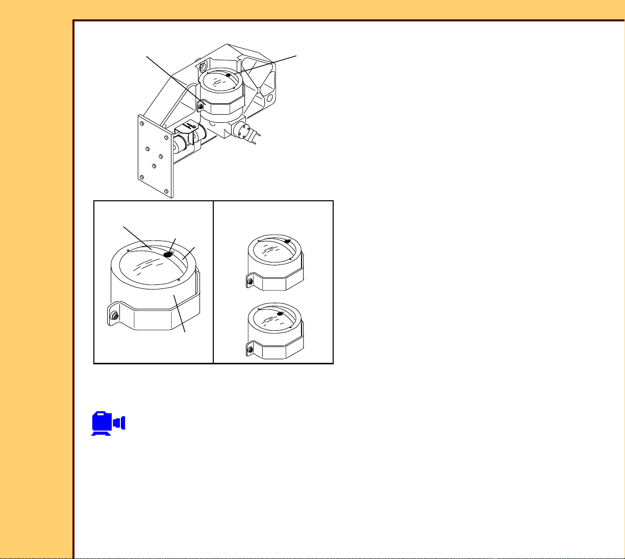
10 Check that the laser beam displays on
F-THETA LENS
laser
beam
the wide RING of the F-THETA LENS
and the reflected light just touches the
upper RING of the F-THETA LENS.
wide
CORRECT NOT CORRECT
RING
H196_2700GCA
H196_2700GC
F-THETA LENS
To Ad j u st :
Press the Escape key to dismiss the video after viewing.
laser
beam
WALL
Class 3B Laser radiation when
open and interlocks defeated.
Avoid exposure to beam.
Page 21
10DEC05
AR4825-1
Page
21 of 160
ADJUSTMENTS AND REPLACEMENTS Adjustments
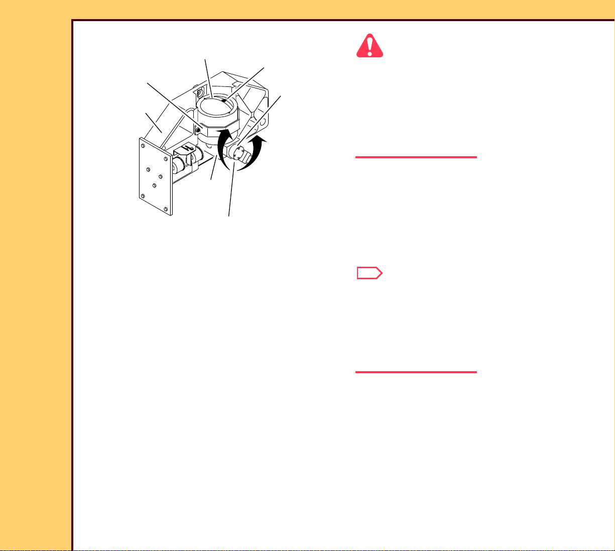
wide RING
F-THETA LENS
OPTICAL AY
laser
beam
GALVO
Caution
• Do not cause damage to the OPTICAL
AY.
• If the laser beam is adjusted below the
wide RING, the error code 1602 occurs
during the Calibration for the Scan
procedure.
n
e
h
w
.
n
d
te
tio
a
ia
d
fe
e
.
d
r ra
m
s
e
a
k
s
e
c
a
b
L
rlo
to
B
te
3
re
in
s
u
s
d
la
a
C
n
e
p
id
o
o
v
A
s
n
o
p
x
e
CLAMP
1 Loosen the SETSCREW in the CLAMP.
2 Rotate the GALVO in the CLAMP until
the laser beam is on the wide RING of
H194_1415ACA
H194_1415AC
SETSCREW
the F-THETA LENS and the reflected
light just touches the upper RING of the
F-THETA LENS.
Note
It may be helpful to place a piece of PAPER
on top of the F-THETA LENS. Rotate the
GALVO until the laser creates a bright spot
on the right side, then rotate the GALVO in
the opposite direction until the bright spot
just disappears.
3 Tighten the SETSCREW in the CLAMP.
4 Do Step 16 - Step 23 of the adjustment procedure for the GALVO BOARD again.
Page 22
10DEC05
AR4825-1
Page
22 of 160
ADJUSTMENTS AND REPLACEMENTS Adjustments
5 Touch:
• [Stop Galvo]
• [Back]
• [Galvo Plot]
• [Star t Galvo Plot]
• [35 x 43]
6 Is the “Wave Form” correct?
Yes No
Continue with Step 7. Do the adjustment for the GALVO BOARD again or use
diagnostics to solve the problem.
Note
It may take 3 cycles of the adjustments to correctly position the GALVO.
Page 23
10DEC05
AR4825-1
Page
23 of 160
ADJUSTMENTS AND REPLACEMENTS Adjustments
7 Loosen the THUMBSCREW.
8 Move the LASER FILTER into the
operation position.
H194_1413GCA
H194_1413GC
6 SCREWS
9 Tighten the THUMBSCREW.
10 Install:
n
e
h
w
.
n
d
io
te
t
a
ia
e
d
f
a
e
.
r
d
r
m
s
e
a
k
s
e
c
a
b
o
L
l
o
r
t
e
B
t
e
3
r
in
s
u
s
d
s
n
o
la
p
a
C
x
n
e
e
p
id
o
o
v
A
• COVER
• 6 SCREWS
COVER
THUMBSCREW
operation
Class 3B Laser radiation when
open and interlocks defeated.
Avoid exposure to beam.
LASER FILTER
position
Postrequisites:
1 Do the adjustments:
• FOLD MIRROR
• GALVO BOARD
2 Do:
• Calibration for the CR 825/850 SYSTEM
• Kodak DirectView TOTAL QUALITY TOOL for CR SYSTEMS
Page 24
10DEC05
AR4825-1
Page
24 of 160
ADJUSTMENTS AND REPLACEMENTS Adjustments
FOLD MIRROR
Adjustment Specification
Purpose: To align the laser beam.
Specification: The laser beam is in the center of each of the SLOTS on the
TOOL TL-5726.
Special Tools: TOOL TL-5726
Prerequisites:
None
To Check:
Press the Escape key to dismiss the video after viewing.
Laser Warning
• This equipment uses a visible red laser. Prevent direct exposure to the beam from the
laser.
• Dangerous Voltage
Page 25
10DEC05
AR4825-1
Page
25 of 160
ADJUSTMENTS AND REPLACEMENTS Adjustments
1 De-energize the system.
4 SCREWS
2 Open the TOP COVER.
PMT COVER
3 Remove:
• FRONT DOOR and RIGHT PANEL
• 4 SCREWS
• PMT COVER
H194_1406GCB
H194_1406GC
Page 26
10DEC05
AR4825-1
Page
26 of 160
ADJUSTMENTS AND REPLACEMENTS Adjustments
OPTICAL AY
Caution
6 SCREWS
Do not cause damage to the OPTICAL AY.
4 Remove:
H194_1412GCA
H194_1412GC
n
e
h
w
.
n
d
o
e
i
t
t
a
a
i
e
d
f
a
e
.
r
d
r
m
s
e
a
k
s
e
c
a
b
o
L
l
o
r
t
e
B
t
e
3
n
r
i
s
u
s
d
s
a
n
o
l
a
p
C
x
n
e
e
d
p
i
o
o
v
A
• 6 SCREWS
• COVER
5 Loosen the THUMBSCREW.
6 Move the LASER FILTER into the
service position.
7 Tighten the THUMBSCREW.
Caution
Class 3B Laser radiation when
open and interlocks defeated.
Avoid exposure to beam.
COVER
THUMBSCREW
service
position
LASER FILTER
Dangerous Voltage
8 Energize the system.
INTERLOCK KEY
H194_0049ACA
H194_0049AC
9 Install the INTERLOCK KEY.
Page 27
10DEC05
AR4825-1
Page
27 of 160
ADJUSTMENTS AND REPLACEMENTS Adjustments
SCREW HEAD
FRAME
TOOL TL-5726
TOOL TL-5726
H194_1406BCA
FRAME
H194_1406BC
Important
The small SLOTS of the TOOL TL-5726 are toward the laser beam. TOOL TL-5726 must be
positioned correctly under the SCREW HEAD.
10 Place the TOOL TL-5726:
• against the FRAME
• under the SCREW HEAD
Page 28
10DEC05
AR4825-1
Page
28 of 160
ADJUSTMENTS AND REPLACEMENTS Adjustments
TOOL
Important
For systems with Software Version ≥ 4.1,
SLOTS
you must have a “Session ID” for access to
“Service Functions” and “Diagnostics”. See
SERVICE BULLETIN 843.
11 At the main menu, touch:
• [Ser vice Functions]
• [Diagnostics]
• [Galvo Test]
• [Treshold]
• [Star t Galvo]
12 Set the “Amplitude” to “3000”.
13 Check that the laser beam is in the
center of the small SLOTS in the TOOL
TL-5726.
H194_0046GCA
H194_0046GC
laser beam
Page 29

ADJUSTMENTS AND REPLACEMENTS Adjustments
10DEC05
AR4825-1
Page
29 of 160
To Ad j u st :
laser beam
A
B
C
D
correct
not correct
1 Deter mine the position of the laser
beam. See the graphic for the
differences.
H194_1407GCA
H194_1407GC
Page 30
10DEC05
AR4825-1
Page
30 of 160
ADJUSTMENTS AND REPLACEMENTS Adjustments
ADJUSTING SCREW B
ADJUSTING SCREW A
SCREW A
SCREW C
ADJUSTING SCREW C
H194_0047ACA
H194_0047AC
SCREW B
2 To adjust the laser beam to the center of the SLOTS in the TOOL TL-5726:
Item Laser Beam Do:
A Left end tilted up or
down
a. Loosen the SCREW A.
b. Rotate the ADJUSTING SCREW A counterclockwise to
move the left end of the laser beam down.
c. Rotate the ADJUSTING SCREW A clockwise to move
the left end of the laser beam up.
B Right end tilted up
or down
d. Tighten the SCREW A.
a. Loosen the SCREW B.
b. Rotate the ADJUSTING SCREW B counterclockwise to
move the right end of the laser beam down.
c. Rotate the ADJUSTING SCREW B clockwise to move
the right end of the laser beam up.
d. Tighten the SCREW B.
Page 31

10DEC05
AR4825-1
Page
31 of 160
ADJUSTMENTS AND REPLACEMENTS Adjustments
Item Laser Beam Do:
CAbove the SLOTSa. Loosen the SCREW C.
b. Rotate the ADJUSTING SCREW C clockwise to move
the laser beam up.
c. Tighten the SCREW C.
D Below the SLOTS a. Loosen the SCREW C.
b. Rotate the ADJUSTING SCREW C counterclockwise to
move the laser beam down.
c. Tighten the SCREW C.
3 Touch:
• [Stop Galvo]
• [Laser “OFF”]
Page 32

10DEC05
AR4825-1
Page
32 of 160
ADJUSTMENTS AND REPLACEMENTS Adjustments
4 Loosen the THUMBSCREW.
5 Move the LASER FILTER into the
6 SCREWS
operation position.
6 Tighten the THUMBSCREW.
7 Install:
n
e
h
w
.
n
d
io
te
t
a
ia
e
d
f
a
e
.
r
d
r
m
s
e
a
k
s
e
c
a
b
o
L
rl
to
e
B
t
e
3
r
in
s
u
s
d
s
n
o
la
a
p
C
x
n
e
e
d
p
i
o
o
v
A
• COVER
• 6 SCREWS
COVER
THUMBSCREW
H194_1413GCA
H194_1413GC
Postrequisite:
1 Do:
• Calibration for the Scan
• Kodak DirectView TOTAL QUALITY TOOL for CR SYSTEMS
Class 3B Laser radiation when
open and interlocks defeated.
Avoid exposure to beam.
operation
position
LASER FILTER
Page 33

10DEC05
AR4825-1
Page
33 of 160
ADJUSTMENTS AND REPLACEMENTS Adjustments
COLLECTOR AY
Adjustment Specification
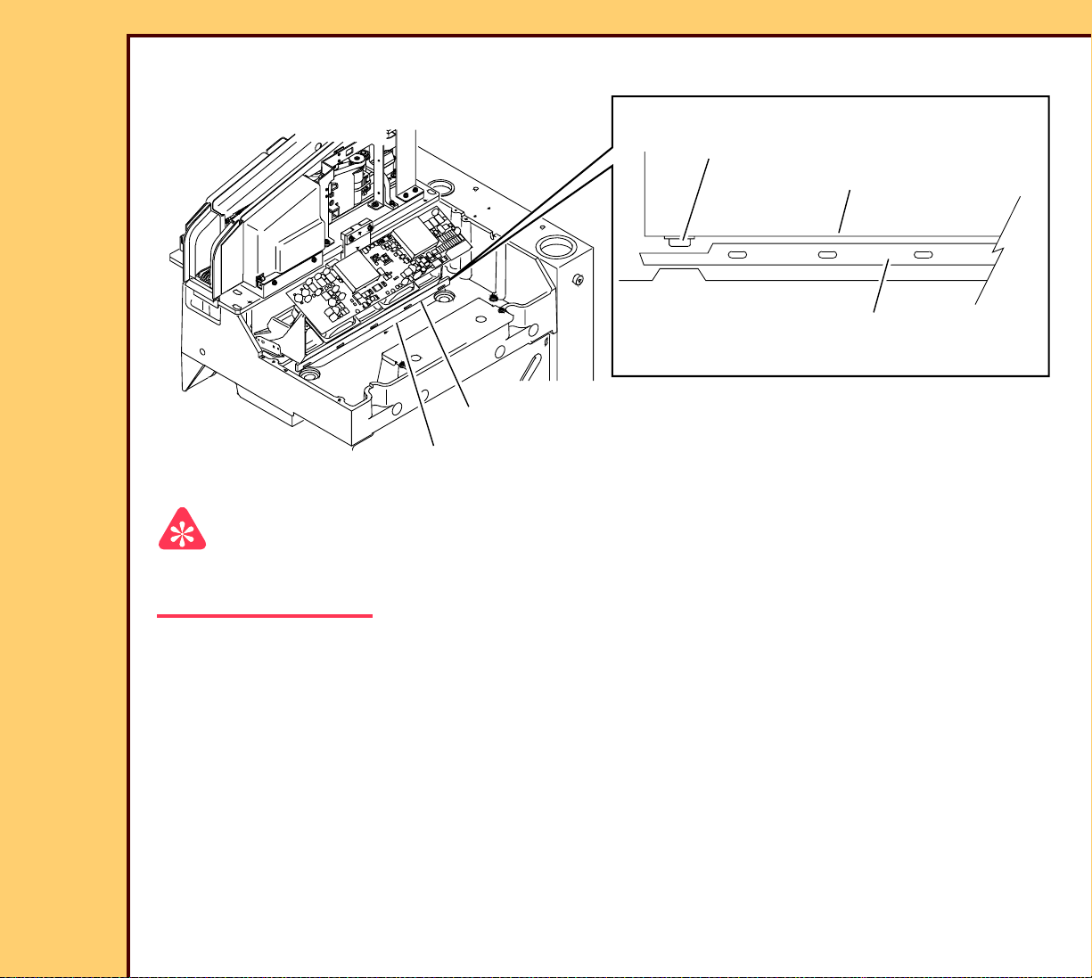
Purpose: To check that the space between the COLLECTOR AY and the
EXTRACTION BAR is correct.
Specification: The COLLECTOR touches the TOOL TL-5727.
Special Tools: TOOL TL-5727
Prerequisites:
None
To Check:
CR850 Serial No. below 8500
CR825 Serial No. below 100
CR850 Serial No. above 8500
CR825 Serial No. above 100
You cannot check this adjustment. COLLECTOR AY is against the
STOP BLOCKS
To Ad j u st :
Press the Escape key to dismiss the video after viewing.
Page 34

10DEC05
AR4825-1
Page
34 of 160
ADJUSTMENTS AND REPLACEMENTS Adjustments
4 SCREWS
Caution
PMT COVER
• Dangerous Voltage
• The PMT/DAS BOARD may be damaged
if POWER CONNECTOR J1 is not
removed before energizing.
CASSETTE
LOAD CRADLE
2 SCREWS
Caution
Dangerous Voltage
4 Energize the system.
H194_1416GCA
H194_1416GC
1 De-energize the system.
2 Open the TOP COVER.
3 Remove:
• 4 SCREWS
• PMT COVER
• 2 SCREWS
• CASSETTE LOAD CRADLE
• POWER CONNECTOR J1 from the
PMT/DAS BOARD
Important
For systems with Software Version ≥ 4.1, you must have a “Session ID” for access to
“Service Functions” and “Diagnostics”. See SERVICE BULLETIN 843.
Page 35

ADJUSTMENTS AND REPLACEMENTS Adjustments
10DEC05
AR4825-1
Page
35 of 160
5 At the main menu, to uch:
• [Ser vice Functions]
• [Diagnostics]
• [Extraction Bar Position]
• [Locate Extraction Bar Home]
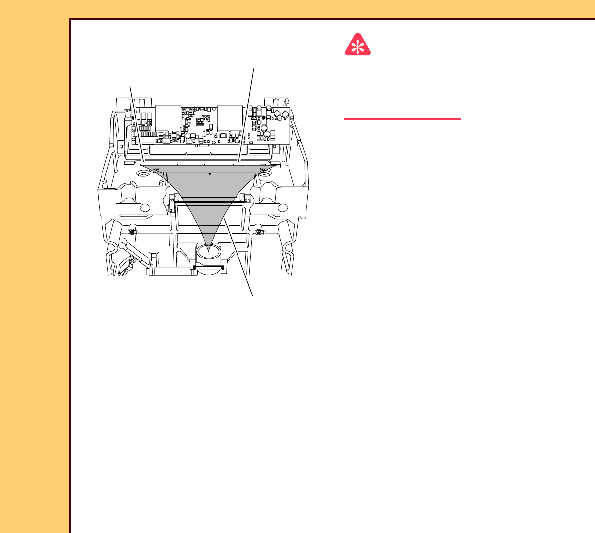
EXTRACTION
BAR
CLAMP
SPRING TENSIONER
EXTRACTION
BAR
TOOL
TL-5727
long end
TOOL
TL-5727
6 Loosen the 2 SCREWS on the
COLLECTOR AY.
7 Move the COLLECTOR AY away from
the EXTRACTION BAR.
8 Touch [Collector adjustment position].
9 Place the TOOL TL-5727 on the
EXTRACTION BAR with the long end
toward the COLLECTOR AY.
10 Move the COLLECTOR AY toward the
TOOL TL-5727.
11 Tighten the 2 SCREWS.
2 SCREWS
COLLECTOR AY
H194_0048GCA
H194_0048GC
12 Remove the TOOL TL-5727.
13 Touch [Return To Home].
14 De-energize the system.
Page 36

10DEC05
AR4825-1
Page
36 of 160
ADJUSTMENTS AND REPLACEMENTS Adjustments
4 SCREWS
15 Install:
• POWER CONNECTOR J1 from the
PMT COVER
PMT/DAS Board
• 4 SCREWS
• PMT COVER
• 2 SCREWS
CASSETTE
LOAD CRADLE
2 SCREWS
H194_1416GCA
H194_1416GC
Postrequisites:
1 Adjust the CASSETTE LOAD CRADLE.
2 Do:
• Calibration for the Scan
• CASSETTE LOAD CRADLE
• Kodak DirectView TOTAL QUALITY TOOL for CR SYSTEMS
Page 37

10DEC05
AR4825-1
Page
37 of 160
ADJUSTMENTS AND REPLACEMENTS Adjustments
INTERMEDIATE PLATE
Adjustment Specification
Purpose: To check that the position of the CASSETTE is aligned with the
EXTRACTION BAR.
Specification: The clearance is correct between the EXTRACTION BAR and the SLED.
Special Tools: TOOL TL-5728
Prerequisites:
None
To Check:
You cannot check this adjustment.
To Ad j u st :
Press the Escape key to dismiss the video after viewing.
Page 38

10DEC05
AR4825-1
Page
38 of 160
ADJUSTMENTS AND REPLACEMENTS Adjustments
1 Open the TOP COVER.
LEFT CASSETTE GUIDE
RIGHT CASSETTE GUIDE
2 Remove:
• 2 COVERS
• 4 SCREWS
• LEFT CASSETTE GUIDE
4 SCREWS
2 COVERS
• RIGHT CASSETTE GUIDE
• 2 SCREWS
• CASSETTE LOAD CRADLE
Important
For systems with Software Version ≥ 4.1,
you must have a “Session ID” for access to
2 SCREWS
“Service Functions” and “Diagnostics”. See
SERVICE BULLETIN 843.
H194_1062GCA
H194_1062GC
CASSETTE
LOAD CRADLE
3 At the main menu, touch:
• [Ser vice Functions]
• [Diagnostics]
• [Extraction Bar Position]
• [Locate Extraction Bar Home]
• [Back]
• [Cam Position Actuation]
• [Unlatch Position]
Page 39

10DEC05
AR4825-1
Page
39 of 160
ADJUSTMENTS AND REPLACEMENTS Adjustments
4 Loosen the 7 SCREWS on the
INTERMEDIATE PLATE.
H194_1046ACA
H194_1046AC
INTERMEDIATE PLATE
7 SCREWS
CASSETTE
END STOP
LEFT
PANEL
EXTRACTION
BAR
CLAMP SPRING
TENSIONER
H194_1036GCA
H194_1036GC
RIGHT PANEL
TOOL TL-5728
SLED
INTERMEDIATE PLATE
COLLECTOR AY
RIGHT
PLUSH AY
FRONT
LIGHT SEAL
5 Open the CLAMP SPRING
TENSIONER.
6 Move the INTERMEDIATE PLATE
toward the COLLECTOR AY.
7 Manually open and hold the RIGHT
PLUSH AY and the FRONT LIGHT
SEAL.
8 Inser t the TOOL TL-5728 on the
EXTRACTION BAR with the thin end
toward the COLLECTOR AY.
Note
The TOOL TL-5728 should touch the
CASSETTE END STOP.
9 Close the CLAMP SPRING
TENSIONER.
Page 40

ADJUSTMENTS AND REPLACEMENTS Adjustments
10DEC05
AR4825-1
Page
40 of 160
10 Move the INTERMEDIATE PLATE toward the LEFT PANEL until the INTERMEDIATE
PLATE stops.
11 Tighten the 7 SCREWS.
12 To safely remove the TOOL TL-5728, touch:
• [Back]
• [Extraction Bar Position]
• [Erase]
13 Open the CLAMP SPRING TENSIONER.
14 Remove the TOOL TL-5728.
15 Close the CLAMP SPRING TENSIONER.
16 Touch:
• [Retur n To Home]
• [Back]
• [Cam Actuation Position]
• [Ho me Cam]
Postrequisites:
1 Adjust the CASSETTE LOAD CRADLE.
Page 41

10DEC05
AR4825-1
Page
41 of 160
ADJUSTMENTS AND REPLACEMENTS Adjustments
CAM SENSOR BOARD A8
Adjustment Specification
Purpose: To check that the DUPLEX CAM home position is correct.
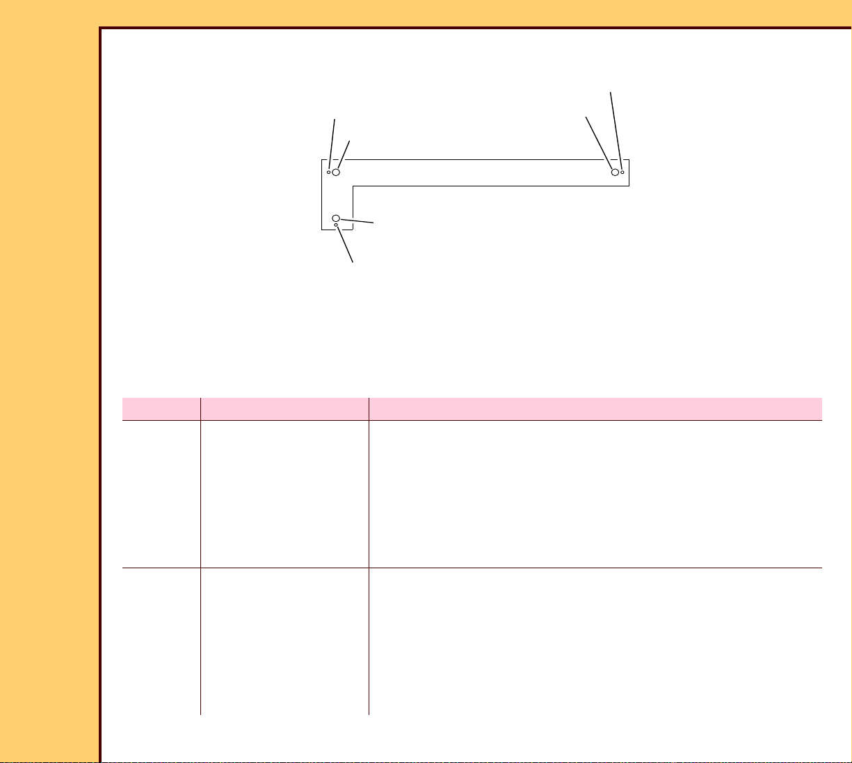
Specification: The height at “A” and “B” from the SLED to the TOOL TL-5724, on the
DUPLEX CAM, is within 1.5 mm (0.060 in.) of each other.
Special Tools: • TOOL TL-5724
• 6-in. SCALE TL-2762
Prerequisites:
None
To Check:
Press the Escape key to dismiss the video after viewing.
Caution
Dangerous Voltage
1 Energize the system.
2 Open the TOP COVER.
Page 42

10DEC05
AR4825-1
Page
42 of 160
ADJUSTMENTS AND REPLACEMENTS Adjustments
Important
For systems with Software Version ≥ 4.1,
you must have a “Session ID” for access to
“Service Functions” and “Diagnostics”. See
TOOL
TL-5724
SERVICE BULLETIN 843.
3 At the main menu, touch:
• [Ser vice Functions]
• [Diagnostics]
• [Cam Position Actuation]
• [Home Cam]
DUPLEX CAM
A
DUPLEX CAM
TOOL TL-5724
SLED
H194_1017ACA
H194_1017AC
B
H194_1037ACA
H194_1037AC
4 Install the TOOL TL-5724 on the
DUPLEX CAM.
5 Hold the TOOL in position.
6 Check that the height at “A” and “B”
from the SLED to the TOOL TL-5724,
on the DUPLEX CAM, is within 1.5 mm
(0.060 in.) of each other.
Page 43

10DEC05
AR4825-1
Page
43 of 160
ADJUSTMENTS AND REPLACEMENTS Adjustments
To Ad j u st :
Press the Escape key to dismiss the video after viewing.
Caution
TOOL
You must remove the TOOL to prevent
damage to the DUPLEX CAM and the
TOOL.
1 Remove the TOOL from the DUPLEX
CAM.
2 Loosen the 2 SCREWS.
DUPLEX CAM
CAM SENSOR BOARD A8
Postrequisites:
None
2 SCREWS
H194_1017ACB
H194_1017AC
3 Move the CAM SENSOR BOARD A8:
• up, if “A” is more than “B”
• down, if “A” is less than “B”
4 Tighten the 2 SCREWS.
5 Touch [Home Cam].
6 Is the adjustment correct?
Yes No
Continue with the
adjustment for the
CAM MOTOR AY.
Do Step 2 -
Step 5 until the
adjustment is
correct.
Page 44

10DEC05
AR4825-1
Page
44 of 160
ADJUSTMENTS AND REPLACEMENTS Adjustments
CAM MOTOR AY
Adjustment Specification
Purpose: To adjust the height of the CAM MOTOR AY to enable the correct timing of
the CAM.
Specification: When the CAM is in the home position, TOOL TL-5722 makes contact with
the SLED CAM FOLLOWER.
Special Tools: TOOL TL-5722
Prerequisites:
1 Adjust the CAM SENSOR BOARD A8.
To Check:
You cannot check this adjustment.
To Ad j u st :
Press the Escape key to dismiss the video after viewing.
Caution
Dangerous Voltage
1 Energize the system.
2 Open the TOP COVER.
3 Remove the LEFT PANEL.
Page 45

10DEC05
AR4825-1
Page
45 of 160
ADJUSTMENTS AND REPLACEMENTS Adjustments
4 Install the INTERLOCK KEY.
Important
For systems with Software Version ≥ 4.1,
you must have a “Session ID” for access to
“Service Functions” and “Diagnostics”. See
SERVICE BULLETIN 843.
5 A the main menu, touch:
• [Ser vice Functions]
• [Diagnostics]
INTERLOCK KEY
H194_0049AC
• [Cam Position Actuation]
H194_0049ACA
• [Home Cam]
Page 46

10DEC05
AR4825-1
Page
46 of 160
ADJUSTMENTS AND REPLACEMENTS Adjustments
6 Loosen:
• 6 SCREWS o n the CAM MOTOR
SLED CAM
FOLLOWER
TOOL TL-5722
BRACKET
• 2 SCREWS o n the ADJUSTMENT
HOLD BRACKET
CAM MOTOR AY
ADJUSTMENT
HOLD BRACKET
H194_1020GCA
H194_1020GC
6 SCREWS
Postrequisites:
1 Adjust:
CAM MOTOR
BRACKET
2 SCREWS
7 Install the TOOL TL-5722.
8 Hold the TOOL in position and press
down on the CAM MOTOR AY until the
TOOL makes contact with the SLED
CAM FOLLOWER.
9 Hold the CAM MOTOR AY down and
tighten the 6 SCREWS on the CAM
MOTOR BRACKET.
10 Move the ADJUSTMENT HOLD
BRACKET down until it reaches the
limit.
11 Tighten the 2 SCREWS on the
ADJUSTMENT HOLD BRACKET.
• SLED CAM FOL LOWER
• CASSETTE END STOP
• REAR CASSETTE SENSOR
Page 47

10DEC05
AR4825-1
Page
47 of 160
ADJUSTMENTS AND REPLACEMENTS Adjustments
SLED CAM FOLLOWER
Adjustment Specification
Purpose: To adjust the front to back position of the SLED to the EXTRACTION BAR.
Specification: The LEFT IDLER ROLLER BRACKET is parallel to the DUPLEX CAM when
the SLED is in the home position.
Special Tools: None
Prerequisites:
1 Adjust:
• CAM SENSOR BOARD A8
• CAM MOTOR AY
To Check:
Press the Escape key to dismiss the video after viewing.
Page 48

10DEC05
AR4825-1
Page
48 of 160
ADJUSTMENTS AND REPLACEMENTS Adjustments
1 Open the TOP COVER.
LEFT CASSETTE GUIDE
RIGHT CASSETTE GUIDE
2 Remove:
• 2 COVERS
• 4 SCREWS
• LEFT CASSETTE GUIDE
4 SCREWS
2 COVERS
• RIGHT CASSETTE GUIDE
• 2 SCREWS
• CASSETTE LOAD CRADLE
2 SCREWS
H194_1062GCA
H194_1062GC
CASSETTE
LOAD CRADLE
Page 49

10DEC05
AR4825-1
Page
49 of 160
ADJUSTMENTS AND REPLACEMENTS Adjustments
IDLER
ROLLER
BRACKET
not correctcorrect
IDLER
ROLLER
BRACKET
For systems with Software Version ≥ 4.1,
you must have a “Session ID” for access to
Important
“Service Functions” and “Diagnostics”. See
SERVICE BULLETIN 843.
3 A the main menu, touch:
• [Ser vice Functions]
DUPLEX CAM
DUPLEX CAM
• [Diagnostics]
• [Extraction Bar Positions]
• [Locate Extraction Bar Home]
• [Back]
• [Cam Position Actuation]
• [Home Cam]
H194_1064GCA
H194_1064GC
To Ad j u st :
Press the Escape key to dismiss the video after viewing.
1 Open the TOP COVER.
4 Check that the LEFT IDLER ROLLER
BRACKET is parallel to the DUPLEX
CAM.
Page 50

10DEC05
AR4825-1
Page
50 of 160
ADJUSTMENTS AND REPLACEMENTS Adjustments
2 Open the CLAMP SPRING
TENSIONER.
CLAMP SPRING TENSIONER
H194_1058ACA
H194_1058AC
3 Loosen the 2 SCREWS on the SLED
2 SCREWS
CAM FOLLOWER.
H194_1066ACA
H194_1066AC
SLED CAM
FOLLOWER
Page 51

10DEC05
AR4825-1
Page
51 of 160
ADJUSTMENTS AND REPLACEMENTS Adjustments
4 Move the SLED backward and forward
not correctcorrect
until the LEFT IDLER ROLLER
BRACKET is parallel to the DUPLEX
CAM.
5 Hold the SLED.
6 Tighten the 2 SCREWS on the SLED
CAM FOLLOWER.
7 Close the CLAMP SPRING
TENSIONER.
8 Check that the adjustment is correct.
H194_1064GC
Postrequisites:
1 Adjust:
• CLAMP BAR
• CASSETTE END STOP
• REAR CASSETTE SENSOR
Page 52

10DEC05
AR4825-1
Page
52 of 160
ADJUSTMENTS AND REPLACEMENTS Adjustments
CLAMP BAR
Adjustment Specification
Purpose: To set the front and back space of the CLAMP BAR.
Specification: • The front space is a minimum of 17.25 mm (0.680 in.).
• The back space is a minimum of 16.25 mm (0.640 in.).
• The difference between the back and front measurement is 0.508 - 1.5
mm (0.020 - 0.060 in.) when the SLED is in the home position.
Special Tools: CALIPER TL-1727 or 15 cm (6 in.) SCALE TL-2762 or equivalent
Prerequisites:
1 Adjust the SLED CAM FOLLOWER.
To Check:
Press the Escape key to dismiss the video after viewing.
Page 53

10DEC05
AR4825-1
Page
53 of 160
ADJUSTMENTS AND REPLACEMENTS Adjustments
LEFT CASSETTE GUIDE
RIGHT CASSETTE GUIDE
Dangerous Voltage
Caution
1 Energize the system.
2 Open the TOP COVER.
4 SCREWS
2 COVERS
3 Remove:
• 2 COVERS
• 4 SCREWS
• LEFT CASSETTE GUIDE
• RIGHT CASSETTE GUIDE
• 2 SCREWS
H194_1062GCA
H194_1062GC
CASSETTE
LOAD CRADLE
2 SCREWS
• CASSETTE LOAD CRADLE
Important
For systems with Software Version ≥ 4.1,
you must have a “Session ID” for access to
“Service Functions” and “Diagnostics”. See
SERVICE BULLETIN 843.
4 At the main menu, touch:
• [Ser vice Functions]
• [Diagnostics]
• [Cam Position Actuation]
• [Home Cam]
Page 54

10DEC05
AR4825-1
Page
54 of 160
ADJUSTMENTS AND REPLACEMENTS Adjustments
5 Use the CALIPER TL-1727 to measure
the front space of the CLAMP BAR.
CALIPER
TL-1727
front
space
6 Is the measurement a minimum of
17.25 mm (0.680 in.) or more?
Yes No
Continue with
Step 7.
Advance to Step 3
of the adjustment
procedure.
SCREW
To Ad j u st :
back space
CLAMP BAR
H194_1040GCA
H194_1040GC
7 Use the CALIPER TL-1727 to measure
the back space of the CLAMP BAR.
8 Is the measurement a minimum of
16.25 mm (0.640 in.) and not more than
the front measurement?
Yes No
Continue with
Step 9.
Advance to Step 2
of the adjustment
procedure.
9 Is the difference between the back and
front measurement 0.508 - 1.5 mm
(0.020 - 0.060 in.)?
Yes No
Checkout
procedure is
complete.
Advance to Step 1
of the adjustment
procedure.
Press the Escape key to dismiss the video after viewing.
Page 55

10DEC05
AR4825-1
Page
55 of 160
ADJUSTMENTS AND REPLACEMENTS Adjustments
Important
Excessive wear or loose parts will cause the front and back space measurement to be wrong.
1 Use the CALIPER TL-1727 to measure
the back space of the CLAMP BAR.
CALIPER
TL-1727
2 Adjust the SCREW until the
measurement is a minimum of 16.25
mm (0.640 in.).
3 Check that the front space
front
space
CLAMP BAR
back space
measurement is a minimum of 17.25
mm (0.680 in.).
4 Is the difference between the back and
front measurement 0.508 - 1.5 mm
(0.020 - 0.060 in.)?
Yes No
Adjustment
procedure is
Do Step 1 -
Step 4 again.
complete.
H194_1040GCA
SCREW
H194_1040GC
Postrequisites:
1 Adjust the RIGHT and LEFT PLUSH AY - Alignment.
Page 56

10DEC05
AR4825-1
Page
56 of 160
ADJUSTMENTS AND REPLACEMENTS Adjustments
CASSETTE END STOP
Adjustment Specification
Purpose: To adjust the position of the CASSETTE END STOP.
Specification: The TOOL TL-5729 touches the EXTRACTION BAR HOOK and CASSETTE
END STOP at the same time.
Special Tools: • TOOL TL-5729
• TOOL TL-5582
Prerequisites:
1 Adjust the SLED CAM FOLLOWER.
To Check:
You cannot check this adjustment.
To Ad j u st :
Press the Escape key to dismiss the video after viewing.
Caution
Dangerous Voltage
1 Energize the system.
2 Open the TOP COVER.
Page 57

10DEC05
AR4825-1
Page
57 of 160
ADJUSTMENTS AND REPLACEMENTS Adjustments
CASSETTE
END STOP
TOOL TL-5582
TOOL TL-5729
For systems with Software Version ≥ 4.1,
Important
you must have a “Session ID” for access to
back HOOK
“Service Functions” and “Diagnostics”. See
SERVICE BULLETIN 843.
SCREW
EXTRACTION BAR
TOOL TL-5582
TOOL TL-5729
YOKE
SCREW
CASSETTE END STOP
H194_1041GCA
H194_1041GC
Postrequisites:
1 Adjust the REAR CASSETTE SENSOR.
3 At the main menu, touch:
• [Ser vice Functions]
• [Diagnostics]
• [Extraction Bar Positions]
• [Locate Extraction Bar Home]
4 Rotate the SCREW counterclockwise 2
rotations.
5 Manually move the YOKE down.
6 Place the TOOL TL-5729 between the
CASSETTE END STOP and the back
HOOK on the EXTRACTION BAR.
7 Adjust the SCREW until the
TOOL TL-5729 touches the HOOK and
CASSETTE END STOP.
Page 58

10DEC05
AR4825-1
Page
58 of 160
ADJUSTMENTS AND REPLACEMENTS Adjustments
REAR CASSETTE SENSOR
Adjustment Specification
Purpose: To adjust the position of the REAR CASSETTE SENSOR.
Specification: The SENSOR BRACKET is at the front limit position of the CASSETTE.
Special Tools: • FEELER GAUGE TL-2372
• 35 x 43 cm CASSETTE
Prerequisites:
1 Adjust:
• SLED CAM FOL LOWER
• CASSETTE END STOP
To Check:
1 See the table in Step 17 of the adjustment procedure.
To Ad j u st :
Press the Escape key to dismiss the video after viewing.
Caution
Dangerous Voltage
1 Energize the system.
2 Open the TOP COVER.
Page 59

10DEC05
AR4825-1
Page
59 of 160
ADJUSTMENTS AND REPLACEMENTS Adjustments
Important
For systems with Software Version ≥ 4.1,
you must have a “Session ID” for access to
35 x 43 cm CASSETTE
“Service Functions” and “Diagnostics”. See
SERVICE BULLETIN 843.
SENSOR
BRACKET
3 At the main menu, touch:
2 SCREWS
CASSETTE
END STOP
1.0 mm (0.040 in.)
FEELER GAUGE
H194_1043GCA
H194_1043GC
• [Ser vice Functions]
• [Diagnostics]
• [Individual Component Control]
4 Remove the 1.0 mm (0.040 in.)
FEELER GAUGE from the FEELER
GAUGE TOOL TL-2372.
5 Install the 1.0 mm (0.040 in.) FEELER
GAUGE on to the 35 x 43 cm
CASSETTE.
6 Load the 35 x 43 cm CASSETTE until
the FEELER GAUGE touches the
CASSETTE END STOP.
7 Obser ve the check box next to the [S3]
CASSETTE REAR SENSOR.
8 Is the “x” displayed in the check box?
Yes No
Advance to
Step 12.
Continue with
Step 9.
9 Loosen the 2 SCREWS on the SENSOR BRACKET.
10 Move the SENSOR BRACKET until the “x” is displayed in the check box.
11 Tighten the 2 SCREWS.
Page 60

ADJUSTMENTS AND REPLACEMENTS Adjustments
10DEC05
AR4825-1
Page
60 of 160
12 Remove:
• 35 x 43 cm CASSETTE
• 1.0 mm (0.040 in.) FEELER GAUGE from the 35 x 43 cm CASSETTE
13 Remove the 1.5 mm (0.060 in.) FEELER GAUGE from the FEELER GAUGE TOOL TL-
2372.
14 Install the 1.5 mm (0.060 in.) FEELER GAUGE on to the 35 x 43 cm CASSETTE.
15 Load the 35 x 43 cm CASSETTE until the FEELER GAUGE touches the CASSETTE
END STOP.
16 Obser ve the check box next to the [S3] CASSETTE REAR SENSOR.
17 Is the “x” displayed in the check box?
Yes No
Do Step 9 - Step 17 until the [S3] CASSETTE
Adjustment procedure is complete.
REAR SENSOR is made with the 1.0 mm
(0.040 in.) FEELER GAUGE installed and not
made with the 1.5 mm (0.060 in.) FEELER
GAUGE installed.
Postrequisites:
None
Page 61

10DEC05
AR4825-1
Page
61 of 160
ADJUSTMENTS AND REPLACEMENTS Adjustments
EXTRACTION BAR HOME POSITION
Adjustment Specification
Purpose: To adjust the home position of the EXTRACTION BAR.
Specification: The TOOL TL-5723 is under the EXTRACTION BAR HOOKS with no end
vertical play.
Special Tools: TOOL TL-5723
Prerequisites:
None
To Check:
Press the Escape key to dismiss the video after viewing.
Page 62

10DEC05
AR4825-1
Page
62 of 160
ADJUSTMENTS AND REPLACEMENTS Adjustments
LEFT CASSETTE GUIDE
RIGHT CASSETTE GUIDE
Dangerous Voltage
Caution
1 Energize the system.
4 SCREWS
2 COVERS
H194_1063GCA
H194_1063GC
2 Remove:
• 2 COVERS
• 4 SCREWS
• LEFT CASSETTE GUIDE
• RIGHT CASSETTE GUIDE
Important
For systems with Software Version ≥ 4.1,
you must have a “Session ID” for access to
“Service Functions” and “Diagnostics”. See
SERVICE BULLETIN 843.
3 At the main menu, touch:
• [Ser vice Functions]
• [Diagnostics]
• [Set Extraction Bar Home]
• [Verify Position]
Page 63

10DEC05
AR4825-1
Page
63 of 160
ADJUSTMENTS AND REPLACEMENTS Adjustments
4 Wait until the EXTRACTION BAR has
TOOL
TL-5723
stopped moving.
5 Touch [Hooks Up].
EXTRACTION
HOOK
H194_1044GCA
H194_1044GC
EXTRACTION BAR
EXTRACTION BAR
6 Place the TOOL TL-5723 under the
EXTRACTION BAR HOOKS on the
EXTRACTION BAR until the end of
both EXTRACTION BAR HOOKS are in
line with the mark on the
TOOL TL-5723.
7 Is the TOOL TL-5723 is under the
EXTRACTION BAR HOOKS with no
vertical play?
Yes No
Checkout
procedure is
complete.
Advance to Step 1
of the adjustment
procedure.
To Ad j u st :
Press the Escape key to dismiss the video after viewing.
1 Remove the TOOL TL-5723.
Page 64

10DEC05
AR4825-1
Page
64 of 160
ADJUSTMENTS AND REPLACEMENTS Adjustments
Important
After “Set Position” is selected, the value will return to 0.0 (+ 5.0 or - 1991).
2 Touch:
• [Ho oks Down]
• [Set Position]
Note
The minimal “up position” is with the top of the EXTRACTION BAR even with the CASSETTE
HANDLING AY.
3 To adjust the height of the HOOK, touch:
• [Fine Nudge Up]
• [Coarse Nudge Up]
• [Fine Nudge Down]
• [Coarse Nudge Down]
4 Touch [Hooks Up].
5 Install TOOL TL-5723.
6 Is the adjustment correct?
Yes No
Continue with Step 7. a. Remove TOOL TL-5723.
b. Touch [Hooks Down].
c. Do Step 3 - Step 6 again.
Important
Do not touch [Save] until the HOOKS are in the correct position.
7 Remove the TOOL TL-5723.
Page 65

ADJUSTMENTS AND REPLACEMENTS Adjustments
10DEC05
AR4825-1
Page
65 of 160
8 Touch:
• [HOOKS DOWN]
• [Save]
Postrequisites:
1 Do Calibration for the Scan.
Page 66

10DEC05
AR4825-1
Page
66 of 160
ADJUSTMENTS AND REPLACEMENTS Adjustments
PLATE POSITIONING AY
Adjustment Specification
Purpose: To adjust the position of the LOWER ARM and the position of the UPPER
ARM.
Specification: • The LOWER ARM touches the TOOL TL-5595.
• The UPPER ARM touches the TOOL TL-5725.
Special Tools: • 2 TOOL TL-5595
• TOOL TL-5725
• LOWER TOOL 9F6387A
Prerequisites:
None
To Check:
Press the Escape key to dismiss the video after viewing.
Page 67

10DEC05
AR4825-1
Page
67 of 160
ADJUSTMENTS AND REPLACEMENTS Adjustments
LEFT CASSETTE GUIDE
RIGHT CASSETTE GUIDE
Dangerous Voltage
Caution
1 Energize the system.
4 SCREWS
2 COVERS
2 Open the TOP COVER.
3 Remove:
• LEF T PANEL
• ERASE LAMP AY
4 Remove:
• 2 COVERS
• 4 SCREWS
• LEFT CASSETTE GUIDE
H194_1063GCA
H194_1063GC
• RIGHT CASSETTE GUIDE
Important
For systems with Software Version ≥ 4.1,
you must have a “Session ID” for access to
“Service Functions” and “Diagnostics”. See
SERVICE BULLETIN 843.
5 At the main menu, touch:
• [Ser vice Functions]
• [Diagnostics]
• [Extraction Bar Positions]
• [Lower Plate Guide Roller Position]
Page 68

10DEC05
AR4825-1
Page
68 of 160
ADJUSTMENTS AND REPLACEMENTS Adjustments
back PLATE
POSITIONING AY
Important
Do not force the TOOL TL-5595 into
front PLATE
POSITIONING AY
position.
6 Place the 2 TOOLS TL-5595 on the
EXTRACTION BAR in the vertical
position, in parallel with both of the
LOWER ARMS of the PLATE
POSITIONING AYs.
7 Do the 2 TOOLS fit between the
LOWER ARMS and the EXTRACTION
BRACKET
BAR?
LOWER ARM
EXTRACTION
BAR
2 TOOLS
TL-5595
H194_1029GCA
H194_1029GC
Yes No
Continue with
Step 8.
Advance to Step 1
of the adjustment
procedure.
8 Check that the 2 TOOLS TL-5595 touch
the LOWER ARMS.
Yes No
Continue with
Step 9.
Advance to Step 1
of the adjustment
procedure.
9 Remove the 2 TOOLS TL-5595 from
the EXTRACTION BAR.
Page 69

10DEC05
AR4825-1
Page
69 of 160
ADJUSTMENTS AND REPLACEMENTS Adjustments
10 Touch:
• [Retur nTo Home]
• [Back]
• [Cam Position Actuation]
TOOL TL-5725
CLAMP SPRING
TENSIONER
LEVER
2 SCREWS
H194_1045GCA
H194_1045GC
• [Unlatch Position]
• [Back]
• [Extraction Bar Positions]
• [Lower Plate Guide Roller Position]
11 Open the CLAMP SPRING
TENSIONER.
12 Install the TOOL TL-5725 with the thin
end toward the right side and the back
against the CASSETTE END STOP.
13 Close the CLAMP SPRING
TENSIONER.
Page 70

10DEC05
AR4825-1
Page
70 of 160
ADJUSTMENTS AND REPLACEMENTS Adjustments
TOOL TL-5725
TOOL
CLAMP SPRING
TENSIONER
TL-5725
UPPER ARM
ADJUSTMENT
BRACKET
UPPER ARM
BRACKET
LEVER
2 SCREWS
H194_1075HCA
H194_1075HC
Important
• The CLAMP SPRING T ENSIONER must be closed.
• Damage to the PLATE POSITIONING AY might cause the UPPER ARM BRACKET to
touch the ADJUSTMENT BRACKET.
14 Check that the TOOL TL-5725 touches both of the UPPER ARMS.
Yes No
The checkout
procedure is
complete and
Advance to Step 9
of the adjustment
procedure.
adjustment is not
necessary.
15 Open the CLAMP SPRING TENSIONER.
Page 71

ADJUSTMENTS AND REPLACEMENTS Adjustments
10DEC05
AR4825-1
Page
71 of 160
16 Remove the TOOL TL-5725.
To Ad j u st :
Press the Escape key to dismiss the video after viewing.
2 PLATE
POSITIONING AYS
SCREW
BRACKET
H194_1028ACA
H194_1028AC
1 Loosen the SCREW on the BRACKET
of both PLATE POSITIONING AYs.
2 Move both of the BRACKETS until both
of the LOWER ARMS touch the 2
TOOLS TL-5595.
3 Tighten the SCREW on the BRACKET
of both PLATE POSITIONING AYs.
4 Remove the 2 TOOLS TL-5595.
5 Touch:
• [Retur n To Home]
• [Back]
• [Cam Position Actuation]
• [Unlatch Position]
• [Back]
• [Extraction Bar Positions]
• [Lower Plate Guide Roller Position]
Page 72

10DEC05
AR4825-1
Page
72 of 160
ADJUSTMENTS AND REPLACEMENTS Adjustments
6 Open the CLAMP SPRING
TOOL TL-5725
TENSIONER.
7 Install the TOOL TL-5725 with the thin
CLAMP SPRING
TENSIONER
end toward the right side and the back
against the CASSETTE END STOP.
8 Close the CLAMP SPRING
TENSIONER.
9 Loosen the 2 SCREWS on both of the
PLATE POSITIONING AYS.
10 Move the LEVER down then up until it
stops.
11 Tighten the 2 SCREWS on both of the
PLATE POSITIONING AYS.
12 Open the CLAMP SPRING
TENSIONER.
13 Remove the TOOL TL-5725.
LEVER
2 SCREWS
Postrequisites:
None
H194_1045GCA
H194_1045GC
14 Close the CLAMP SPRING
TENSIONER.
15 Touch:
• [Retur n To Home]
• [Back]
• [Cam Position Actuation]
• [Home Cam]
Page 73

10DEC05
AR4825-1
Page
73 of 160
ADJUSTMENTS AND REPLACEMENTS Adjustments
RIGHT and LEFT PLUSH AY - Alignment
Adjustment Specification
Purpose: To align the RIGHT and LEFT PLUSH AY.
Specification: With the RIGHT PLUSH AY adjusted to 7 - 8 mm (0.25 - 0.30 in.) from the
end of the 18 x 24 cm CASSETTE, the LEFT PLUSH AY SHUTTERS must
not touch the RIGHT PLUSH AY.
Special Tools: 6-in. SCALE TL-2762
Prerequisites:
1 Adjust:
• SLED CAM FOL LOWER
• CLAMP BAR
To Check:
Press the Escape key to dismiss the video after viewing.
Page 74

10DEC05
AR4825-1
Page
74 of 160
ADJUSTMENTS AND REPLACEMENTS Adjustments
1 Open the TOP COVER.
LEFT CASSETTE GUIDE
2 Remove:
RIGHT CASSETTE GUIDE
• 2 COVERS
• 4 SCREWS
4 SCREWS
2 COVERS
H194_1063GCA
H194_1063GC
• LEFT CASSETTE GUIDE
• RIGHT CASSETTE GUIDE
Caution
Dangerous Voltage
3 Energize the system.
Important
For systems with Software Version ≥ 4.1,
you must have a “Session ID” for access to
“Service Functions” and “Diagnostics”. See
SERVICE BULLETIN 843.
4 At the main menu, touch:
• [Ser vice Functions]
• [Diagnostics]
• [Cam Position Actuation]
• [Load Cassette]
Page 75

10DEC05
AR4825-1
Page
75 of 160
ADJUSTMENTS AND REPLACEMENTS Adjustments
5 Load the 18 x 24 cm CASSETTE.
CASSETTE
CASSETTE
6 Check for a 7 - 8 mm (0.25 - 0.30 in.)
clearance from the end of the
CASSETTE to the PLUSH BRACKET.
Yes No
7-8 mm
(0.25 -
0.30 in.)
PLUSH BRACKET
Continue with
Step 7.
Advance to Step 1
of the adjustment
procedure.
H194_1048ACA
H194_1048AC
2 SCREWS
LEFT
PLUSH AY
SHUTTER
.76 mm
(0.030 in.)
PLUSH
BRACKET
RIGHT
PLUSH AY
H194_1067ACA
H194_1067AC
7 Check that the left PLUSH AY
SHUTTERS are 0.76 mm (0.030 in.)
from the RIGHT PLUSH AY.
Yes No
The checkout
procedure is
complete.
Advance to Step 4
of the adjustment
procedure.
8 Touch [Eject Cassette].
Page 76

ADJUSTMENTS AND REPLACEMENTS Adjustments
10DEC05
AR4825-1
Page
76 of 160
To Ad j u st :
Press the Escape key to dismiss the video after viewing.
CASSETTE
RIGHT PLUSH AY
2 SCREWS
2 SCREWS
H194_1051ACA
H194_1051AC
1 Loosen the 2 SCREWS.
2 Move the right PLUSH AY into the
correct position.
3 Tighten the 2 SCREWS.
4 Loosen the 2 SCREWS on the LEFT
PLUSH AY.
LEFT
PLUSH AY
SHUTTER
Postrequisites:
None
.76 mm
(0.030 in.)
RIGHT
PLUSH AY
H194_1067ACA
H194_1067AC
5 Align the left PLUSH AY SHUTTERS to
be 0.76 mm (0.030 in) from the RIGHT
PLUSH AY.
6 Tighten the 2 SCREWS.
7 Eject the CASSETTE.
Page 77

10DEC05
AR4825-1
Page
77 of 160
ADJUSTMENTS AND REPLACEMENTS Adjustments
LEFT PLUSH AY - Vertical Position
Adjustment Specification
Purpose: To adjust the vertical position of the LEFT PLUSH AY.
Specification: The LEFT PLUSH ARM is vertical to the LEFT PLUSH AY BRACKET.
Special Tools: None
Prerequisites:
1 Adjust:
• SLED CAM FOL LOWER
• CLAMP BAR
Page 78

ADJUSTMENTS AND REPLACEMENTS Adjustments
10DEC05
AR4825-1
Page
78 of 160
To Check:
4 SCREWS
H194_1062GCA
H194_1062GC
LEFT CASSETTE GUIDE
RIGHT CASSETTE GUIDE
2 COVERS
2 SCREWS
CASSETTE
LOAD CRADLE
1 Open the TOP COVER.
2 Remove:
• 2 COVERS
• 4 SCREWS
• LEFT CASSETTE GUIDE
• RIGHT CASSETTE GUIDE
• 2 SCREWS
• CASSETTE LOAD CRADLE
Caution
Dangerous Voltage
3 Energize the system.
Important
For systems with Software Version ≥ 4.1,
you must have a “Session ID” for access to
“Service Functions” and “Diagnostics”. See
SERVICE BULLETIN 843.
4 At the main menu, touch:
• [Ser vice Functions]
• [Diagnostics]
• [Cam Position Actuation]
• [Home Cam]
Page 79

10DEC05
C
A
AR4825-1
Page
79 of 160
ADJUSTMENTS AND REPLACEMENTS Adjustments
5 Check that the left PLUSH ARM AY is
vertical to the left PLUSH AY
PLUSH
ARM AY
PLUSH AY
BRACKET
SPRING
BRACKET
BRACKET.
2 SCREWS
H194_1069GC
H194_1069G
Page 80

ADJUSTMENTS AND REPLACEMENTS Adjustments
10DEC05
AR4825-1
Page
80 of 160
To Ad j u st :
PLUSH
ARM AY
PLUSH AY
BRACKET
1 Loosen the 2 SCREWS.
2 Move the SPRING BRACKET until the
left PLUSH ARM AY is ver tical to the
left PLUSH AY BRACKET.
3 Tighten the 2 SCREWS.
SPRING
BRACKET
2 SCREWS
Postrequisites:
1 Adjust:
• SLED CAM FOL LOWER
• CLAMP BAR
• CASSETTE END STOP
• REAR CASSETTE SENSOR
H194_1069GCA
H194_1069GC
Page 81

10DEC05
AR4825-1
Page
81 of 160
ADJUSTMENTS AND REPLACEMENTS Adjustments
INTERNAL BAR CODE READER
Adjustment Specification
Purpose: To check the alignment of the INTERNAL BAR CODE READER.
Specification: When you install the BAR CODE ALIGNMENT TOOL TL-5600 and touch
[READ CASSETTE ID] the MONITOR displays “x222222222”.
Special Tools: BAR CODE ALIGNMENT TOOL TL-5600
Prerequisites:
None
To Check:
Caution
Dangerous Voltage
1 Energize the system.
2 Open the TOP COVER.
3 Close the FRONT DOOR.
HANDLE
4 PINS
BAR CODE
ALIGNMENT
TOOL TL-5600
WINDOW
H194_1024ACA
H194_1024AC
4 Seat the 4 PINS of the BAR CODE
ALIGNMENT TOOL TL-5600 in the
WINDOW of the EXTRACTION BAR.
5 Hold the HANDLE vertically.
Page 82

10DEC05
AR4825-1
Page
82 of 160
ADJUSTMENTS AND REPLACEMENTS Adjustments
Important
For systems with Software Version ≥ 4.1, you must have a “Session ID” for access to
“Service Functions” and “Diagnostics”. See SERVICE BULLETIN 843.
6 At the main menu, to uch:
• [Ser vice Functions]
• [Diagnostics]
• [Component Control: Step]
• [READ CASSETTE ID]
Important
The “Status” might read “The bar code is backwards”, this is normal.
7 Check that the CASSETTE ID “x222222222” is displayed.
To Ad j u st :
1 Remove the LEFT PANEL.
Page 83

10DEC05
AR4825-1
Page
83 of 160
ADJUSTMENTS AND REPLACEMENTS Adjustments
2 Loosen the 2 SCREWS.
2 SCREWS
BRACKET
H194_1025ACA
H194_1025AC
3 If the displayed value is:
“x333333333” “x111111111” “Error”
a. Move the BRACKET
up a minimum
distance.
b. Tighten the
2 SCREWS.
a. Move the BRACKET
down a minimum
distance.
b. Tighten the 2 SCREWS.
a. Move the BRACKET a
minimum distance in either
direction until numbers
display.
b. Tighten the 2 SCREWS.
4 Touch [READ CASSETTE ID] again.
Page 84

10DEC05
AR4825-1
Page
84 of 160
ADJUSTMENTS AND REPLACEMENTS Adjustments
BAR CODE ALIGNMENT
TOOL
bar code 9111111111
Important
If the reading at either edge of the bar code
is “x222222222”, the adjustment will not
hold.
5 Check that the BAR CODE READER is
bar code 9333333333
bar code 9222222222
Correct
reading at the center of the bar code
“x222222222”.
a Make a mark on the BRACKET for
the position of the SCREW.
b Move the BRACKET in the same
direction that you did during Step 3
Not Correct
H177_2483ACA
H177_2483AC
until “x333333333” or “x111111111”
displays on the MONITOR.
H194_1026ACA
H194_1026AC
mark
BRACKET
2 SCREWS
c Tighten the 2 SCREWS.
d Make another mark on the
BRACKET for the new position of
the SCREW.
e Move the BRACKET until the
SCREW is in the center of the 2
marks.
f Tighten the 2 SCREWS.
g Check that “x222222222” displays
on the MONITOR.
Page 85

10DEC05
AR4825-1
Page
85 of 160
ADJUSTMENTS AND REPLACEMENTS Adjustments
Important
The BRACKET must be at a 31-degree
BRACKET
angle.
31 degree
angle
H177_2481ACA
H177_2481AC
9 Is the angle of the BRACKET correct?
Yes No
The INTERNAL BAR
CODE READER
adjustment procedure is
a. Install a new BRACKET.
b. Continue with Step 10.
complete.
10 Do Step 2 - Step 3 again.
6 If “x2222222222” does not display on
the MONITOR, remove the BRACKET.
7 Compare the angle of the BRACKET
with the BRACKET in the graphic.
8 Hold the BRACKET against the image
on the screen of your computer.
Postrequisites:
None
Page 86

10DEC05
AR4825-1
Page
86 of 160
ADJUSTMENTS AND REPLACEMENTS Adjustments
CASSETTE LOAD CRADLE
Adjustment Specification
Purpose: To make the CASSETTE LOAD CRADLE align with the CASSETTE.
Specification: The CASSETTE LOAD CRADLE is aligned with the CASSETTE, the
CASSETTE GUIDES and the EXTRACTION BAR.
Special Tools: 18 x 24 cm CASSETTE
Prerequisites:
None
To Check:
You cannot check this adjustment.
To Ad j u st :
1 Open the TOP COVER.
2 Energize the system.
Important
For systems with Software Version ≥ 4.1, you must have a “Session ID” for access to
“Service Functions” and “Diagnostics”. See SERVICE BULLETIN 843.
3 Touch:
• [Ser vice Functions]
• [Diagnostics]
• [Extraction Bar Position]
• [Home Position]
• [Back]
• [Cam Position Actuation]
Page 87

ADJUSTMENTS AND REPLACEMENTS Adjustments
10DEC05
AR4825-1
Page
87 of 160
• [Ho me Cam]
CASSETTE
CASSETTE
GUIDES
CASSETTE
LOAD
CRADLE
CASSETTE
LOAD CRADLE
1 - 2 mm
(0.04 - 0.08 in.)
EXTRACTION
BAR
CASSETTE
TONGUE
4 Loosen the 2 SCREWS.
5 Position a 18 x 24 cm CASSETTE.
6 Move:
• CASSETTE LOAD CRADLE until the
vertical clearance between the
CASSETTE and the TONGUE is
1 - 2 mm (0.04 - 0.08 in.)
• CASSETTE LOAD CRADLE in the
center from side to side with the
CASSETTE GUIDES
Note
If you touch the CASSETTE at the front, it
should move down and up.
7 Hold the CASSETTE LOAD CRADLE
and tighten the 2 SCREWS.
CASSETTE
2 SCREWS
Postrequisites:
None
CASSETTE
LOAD CRADLE
H194_1042GCA
H194_1042GC
8 Check that the adjustment is correct.
9 Remove the CASSETTE.
Page 88

10DEC05
AR4825-1
Page
88 of 160
ADJUSTMENTS AND REPLACEMENTS Replacements
Section 2: Replacements
GALVO and BLOCK AY
Prerequisites:
None
To Remove:
Caution
Dangerous Voltage
1 De-energize the system.
2 Remove the FRONT DOOR and RIGHT PANEL.
Caution
Do not cause damage to the OPTICAL AY.
SHOCK WATCH
H194_1400ACA
H194_1400AC
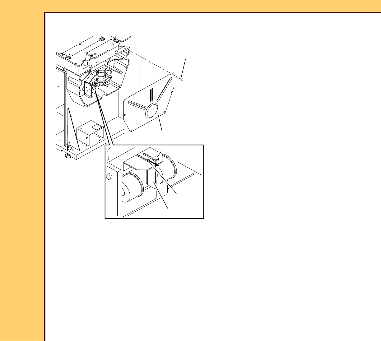
3 Remove:
• 6 SCREWS
• COVER
Page 89

10DEC05
AR4825-1
Page
89 of 160
ADJUSTMENTS AND REPLACEMENTS Replacements
4 Disconnect the CONNECTOR.
5 Loosen the SCREW.
6 Remove the GALVO.
n
e
h
w
.
n
d
te
tio
a
ia
d
fe
e
.
d
r ra
m
s
e
a
k
s
e
c
a
b
L
rlo
to
B
te
3
re
in
s
u
s
d
s
n
o
la
a
C
xp
n
e
e
p
id
o
o
v
A
CONNECTOR
H194_1417ACA
H194_1417AC
SCREW
GALVO
To Install:
1 Reverse the steps in the removal procedure.
Postrequisites:
1 Adjust:
• GALVO BOARD
• GALVO ROTATION
• FOLD MIRROR
2 Do the Calibration for the CR 825/850 SYSTEM.
Page 90

10DEC05
AR4825-1
Page
90 of 160
ADJUSTMENTS AND REPLACEMENTS Replacements
OPTICS MODULE
Prerequisites:
None
To Remove:
Press the Escape key to dismiss the video after viewing.
Caution
Dangerous Voltage
H194_1402GCA
H194_1402GC
lass 3B Laser radiatio
C
open and
void
A
CONNECTOR J2
ground wire
hen
n w
d.
te
efea
.
eam
rlocks d
inte
sure to b
xpo
e
OPTICS
MODULE
3 SCREWS
1 De-energize the system.
2 Remove the FRONT DOOR and RIGHT
PANEL.
ESD
Possible damage from electrostatic discharge.
3 Disconnect:
• CONNECTOR J2
• GROUND wire
• 3 SCREWS
• OPTICS MODUL E
Page 91

ADJUSTMENTS AND REPLACEMENTS Replacements
10DEC05
AR4825-1
Page
91 of 160
To Install:
1 Reverse the steps in the removal procedure.
Postrequisites:
1 Do Setting the Laser Calibration Voltage.
2 Adjust:
• GALVO ROTATION
• GALVO BOARD
• FOLD MIRROR
3 Do the Calibration for the Scan.
Page 92

10DEC05
AR4825-1
Page
92 of 160
ADJUSTMENTS AND REPLACEMENTS Replacements
PMT/DAS BOARD
Prerequisites:
None
To Remove:
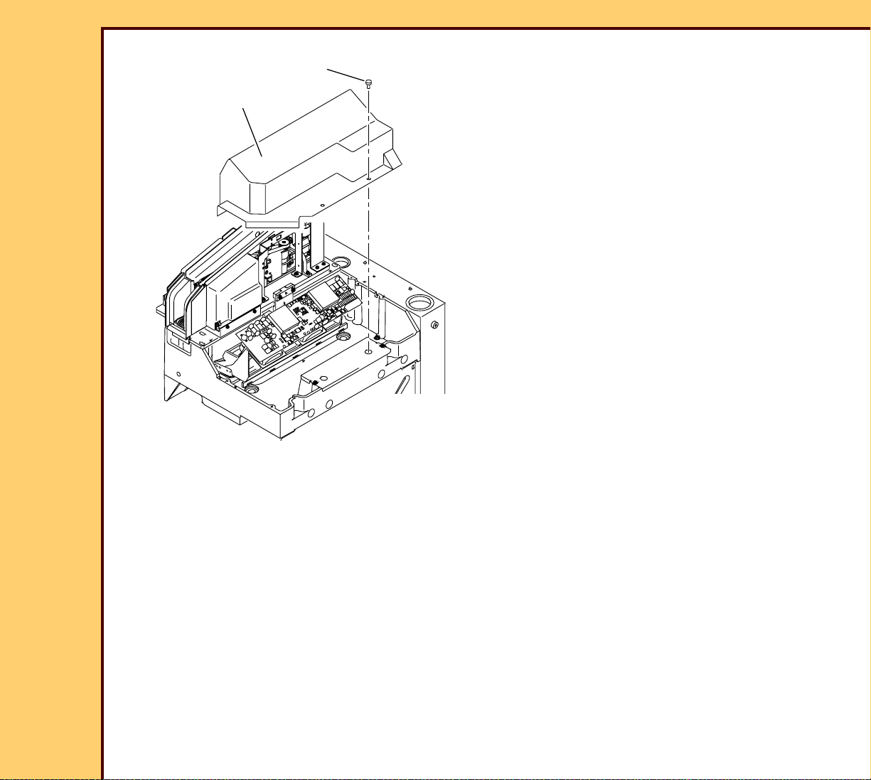
4 SCREWS
PMT COVER
2 SCREWS
Dangerous Voltage
Possible damage from electrostatic discharge.
Caution
1 De-energize the system.
2 Open the TOP COVER.
ESD
3 Remove:
CONNECTOR
J2
CONNECTOR J1
PMT/DAS BOARD
H194_0021GCA
H194_0021GC
SCREW
GROUND STRAP
To Install:
1 Reverse the steps in the removal procedure.
• 5 SCREWS
• PMT COVER
• CONNECTOR J1
• CONNECTOR J2
• SCREW
• ground STRAP
• 2 SCREWS
• PMT/DAS BOARD
Page 93

ADJUSTMENTS AND REPLACEMENTS Replacements
10DEC05
AR4825-1
Page
93 of 160
Postrequisites:
1 Do the Calibration for the CR 825/850 SYSTEM.
Page 94

10DEC05
AR4825-1
Page
94 of 160
ADJUSTMENTS AND REPLACEMENTS Replacements
PMTs and COLLECTOR AY
Prerequisites:
None
To Remove:
2 SCREWS
COVER
2 PMTs
COLLECTOR AY
2 SCREWS
Caution
Dangerous Voltage
1 De-energize the system.
FOAM
2 Open the TOP COVER.
3 Remove the PMT/DAS BOARD.
ESD
Possible damage from electrostatic discharge.
4 Remove:
• 2 SCREWS
• COLLECTOR AY
• 2 SCREWS
• COVER
• FOAM
H194_0022GCA
H194_0022GC
• 2 PMTs
Page 95

ADJUSTMENTS AND REPLACEMENTS Replacements
10DEC05
AR4825-1
Page
95 of 160
To Install:
Caution
Do not damage the PMT.
1 Reverse the steps in the removal procedure.
Postrequisites:
1 Adjust the COLLECTOR AY.
2 Do the “Calibration for the CR 825/850 SYSTEM.
Page 96

10DEC05
AR4825-1
Page
96 of 160
ADJUSTMENTS AND REPLACEMENTS Replacements
FOLD MIRROR
Prerequisites:
None
To Remove:
PMT COVER
FOLD MIRROR
COVER
H194_0050GCA
H194_0050GC
5 SCREWS
2 PLUGS
FOLD
MIRROR
3 SCREWS
Caution
Dangerous Voltage
1 De-energize the system.
2 Remove the FRONT DOOR and RIGHT
PANEL.
3 Remove:
• 5 SCREWS
• PMT COVER
• FOLD MIRROR COVER
• 2 PLUGS
• 3 SCREWS
• FOLD MIRROR
To Install:
1 Reverse the steps in the removal procedure.
Postrequisites:
1 Adjust the FOLD MIRROR.
2 Do the Calibration for the Scan.
Page 97

10DEC05
AR4825-1
Page
97 of 160
ADJUSTMENTS AND REPLACEMENTS Replacements
CASSETTE HANDLING AY
Prerequisites:
None
Page 98

ADJUSTMENTS AND REPLACEMENTS Replacements
10DEC05
AR4825-1
Page
98 of 160
To Remove:
SLED CAM
FOLLOWER
CONNECTOR P2
2 SCREWS
SHOULDER
SCREW
WASHER
ACTUATOR
ARM
BEARING
BRACKET
2 SCREWS
Caution
Dangerous Voltage
1 De-energize the system.
2 Open the TOP COVER.
3 Disconnect the CONNECTOR P2.
4 Open the CLAMP SPRING
TENSIONER.
5 Remove:
• 2 SCREWS
• CASSETTE LOAD CRADLE
• 4 SCREWS
• 2 BEARING BRACKETS
• 2 SCREWS
CASSETTE
HANDLING
AY
4 SCREWS
2 BEARING
BRACKETS
H194_1001CCA
H194_1001CC
4 SCREWS
4 ground
straps
CASSETTE
LOAD
CRADLE
2 SCREWS
• SLED CAM FOLLOWER
• 2 SCREWS
• BEARING BRACKET
• SHOULDER SCREW
• WASHER
• 4 GROUND STRAPS
6 Disengage the ACTUATOR ARM.
7 Remove the CASSETTE
HANDLING AY.
Page 99

ADJUSTMENTS AND REPLACEMENTS Replacements
10DEC05
AR4825-1
Page
99 of 160
To Install:
SLED CAM
FOLLOWER
CONNECTOR P2
2 SCREWS
SHOULDER
SCREW
WASHER
CLAMP SPRING
TENSIONER
BEARING
BRACKET
2 SCREWS
1 Open the CLAMP SPRING
TENSIONER.
2 Install the CASSETTE HANDLING AY
into the BEARING GROOVE on the
INTERMEDIATE PLATE.
3 Install:
• 2 BEARING BRACKETS
• 4 SCREWS
• BEARING BRACKET
• 2 SCREWS
• SLED CAM FOLLOWER
• 2 SCREWS
• SHOULDER SCREW
• WASHER
4 SCREWS
2 BEARING
BRACKETS
4 SCREWS
H194_1001CCB
H194_1001CC
4 ground
straps
• 2 SCREWS
• CASSETTE LOAD CRADLE
• CONNECTOR P2
• 4 GROUND STRAPS
4 Close the CLAMP SPRING
TENSIONER.
CASSETTE
LOAD
CRADLE
2 SCREWS
Page 100

ADJUSTMENTS AND REPLACEMENTS Replacements
10DEC05
AR4825-1
Page
100 of 160
Postrequisites:
1 Did you install a new CASSETTE HANDLING AY?
Yes No
Adjust:
• CAM MOTOR AY
• SLED CAM FOL LOWER
• CASSETTE END STOP
• REAR CASSETTE SENSOR
• EXTRACTION BAR HOME POSITION
• CLAMP BAR
• RIGHT and LEFT PLUSH AY -
Alignment
• LEFT PLUSH AY - Vertical Position
Adjust the SLED CAM FOLLOWER.
 Loading...