

Page 1
Kodak DirectView CR 800/CR 900
Series
H196_0501HC
User’s Guide
Page 2

Eastman Kodak Company
343 State Street
Rochester, NY 14650
© Eastman Kodak Company, 2003
Kodak, Archive Manager, Digital Science, DirectView, Dryview, Ektascan and Min-R are trademarks of Eastman Kodak Company.
PN 1F3742
Page 3

Table of Contents
1 Safety and Related Information
Health and Safety Compliance ..........................................................................................................................1-7
CR 800/900 Systems...................................................................................................................................1-7
CR 850/950 Systems...................................................................................................................................1-8
Remote Operations Panel...........................................................................................................................1-9
User Guide Conventions ...........................................................................................................................1-10
Special Messages................................................................................................................................1-10
2 Overview
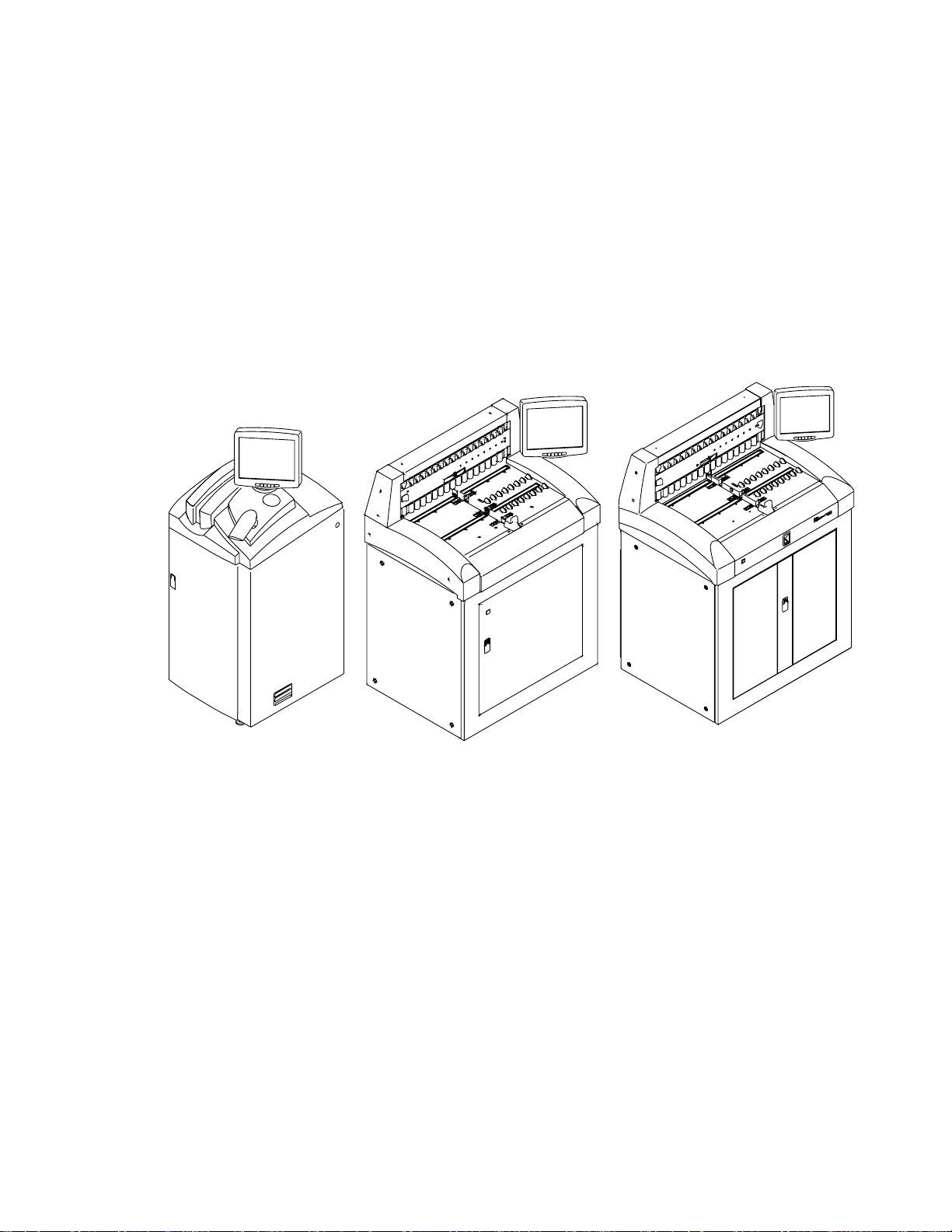
Product Description ......................................................................................................................................... 2-1
CR 800/850 System Components ......................................................................................................................2-2
CR 900/950 System Components ......................................................................................................................2-3
Touch Screen Monitor ...............................................................................................................................2-4
Internal PC.................................................................................................................................................2-4
Cassettes ....................................................................................................................................................2-4
Remote Operations Panel.................................................................................................................................2-5
Site Operating Configurations ...........................................................................................................................2-5
Network Configuration ...............................................................................................................................2-5
Workflow .........................................................................................................................................................2-7
Workflow Definitions .................................................................................................................................2-7
Workflow Diagram.....................................................................................................................................2-8
3 Operation and Main Menu
Starting the CR System......................................................................................................................................3-1
Logging on to the Operator Console (Option) ..................................................................................................3-2
Changing your Password ............................................................................................................................3-2
Shutting down the CR System............................................................................................................................3-2
Rebooting the System .......................................................................................................................................3-3
Power Failures ................................................................................................................................................. 3-4
Operating Modes..............................................................................................................................................3-4
Pass-through Mode ....................................................................................................................................3-4
QA Mode....................................................................................................................................................3-4
Main Menu.......................................................................................................................................................3-5
June 3, 2003 1F3742 i
Page 4

Table of Contents
Main Menu Functions.................................................................................................................................3-5
Main Menu Screen Navigation Buttons .......................................................................................................3-6
Using the Touch Screen....................................................................................................................................3-7
Navigation Buttons .....................................................................................................................................3-7
Error Messages ..........................................................................................................................................3-7
Virtual Keyboards .............................................................................................................................................3-8
Standard Alphanumeric Virtual Keyboard ...................................................................................................3-8
Standard Numeric Virtual Datepad .............................................................................................................3-9
Special Keyboards ......................................................................................................................................3-9
Entering Information into Data Fields.............................................................................................................3-10
4 Exam Data Entry
Manual Data Entry............................................................................................................................................4-1
Entering Patient Information ............................................................................................................................4-3
New Patient ................................................................................................................................................4-3
Trauma Patient...........................................................................................................................................4-4
Existing Patient...........................................................................................................................................4-4
New Study ..................................................................................................................................................4-6
Entering Exam Information ..............................................................................................................................4-7
Using Procedure Codes and Procedure Mapping........................................................................................4-7
Mandatory Exam Information.....................................................................................................................4-8
Optional Exam Information ........................................................................................................................4-9
Saving the Patient and Exam Information .................................................................................................4-10
5 Scanning, Viewing and Printing Images
Performing an Exam ........................................................................................................................................5-1
Loading Cassettes .............................................................................................................................................5-3
CR 800/850 System ....................................................................................................................................5-3
CR 900 System ...........................................................................................................................................5-4
CR 950 System ...........................................................................................................................................5-6
Viewing Images ................................................................................................................................................5-7
Viewing an Image in Pass-through Mode ....................................................................................................5-7
Viewing Images in QA Mode.......................................................................................................................5-7
Working with Images .....................................................................................................................................5-10
Reprocessing Images ...............................................................................................................................5-10
Routing Images ........................................................................................................................................5-10
Erasing Screens........................................................................................................................................5-11
Reviewing Images.....................................................................................................................................5-13
Managing Images ...........................................................................................................................................5-15
Managing Failed Delivery Images .............................................................................................................5-16
Managing Unassigned Images...................................................................................................................5-16
Printing Images..............................................................................................................................................5-18
ii 1F3742 June 3, 2003
Page 5

Table of Contents
Printing Multi-format Images................................................................................................................... 5-21
Other Multi-format Settings...................................................................................................................... 5-25
Multi-format Only Check Box............................................................................................................. 5-25
Image Review Screen......................................................................................................................... 5-25
Deleting Multi-format Images ............................................................................................................ 5-26
Printing Text.................................................................................................................................................. 5-26
Printing Internal Text Boxes .................................................................................................................... 5-27
Printing External Text Boxes.................................................................................................................... 5-28
True-size Printing (Option) ........................................................................................................................... 5-29
1 cm Tick Marks ..................................................................................................................................... 5-31
6 Maintaining Image Quality
Guidelines for Optimizing Image Quality.......................................................................................................... 6-1
Performing the Exam................................................................................................................................. 6-1
Image Processing ...................................................................................................................................... 6-1
Changing Image Orientation ...................................................................................................................... 6-2
Adjusting Contrast and Brightness.............................................................................................................. 6-2
Changing Window Widths (Contrast)................................................................................................... 6-2
Changing Window Levels (Brightness)................................................................................................. 6-2
Changing Image Tonescale ........................................................................................................................ 6-3
Image Processing ............................................................................................................................................ 6-4
Improving Image Characteristics ..................................................................................................................... 6-7
7 Troubleshooting
Error Messages................................................................................................................................................ 7-1
Releasing Cassette Jams................................................................................................................................... 7-1
System Reset.................................................................................................................................................... 7-1
System Status................................................................................................................................................... 7-2
Clear Pending Images...................................................................................................................................... 7-2
Slow System Response .................................................................................................................................... 7-2
Incorrect Image Grouping ............................................................................................................................... 7-2
Modifying Patient Information ................................................................................................................... 7-3
8 Maintaining Equipment and Cassettes
Cleaning the CR System Surfaces...................................................................................................................... 8-1
Cleaning the ROP Touch Screen....................................................................................................................... 8-1
Cleaning Storage Phosphor Screens................................................................................................................. 8-2
Special Cleaning Materials......................................................................................................................... 8-2
Removing the Phosphor Screen ................................................................................................................. 8-2
Cleaning the Phosphor Screen ................................................................................................................... 8-3
Replacing the Phosphor Screen ....................................................................................................................... 8-4
Cassette Cautions ............................................................................................................................................. 8-5
June 3, 2003 1F3742 iii
Page 6

Table of Contents
Cleaning Cassettes ............................................................................................................................................8-6
Replacing Erase Lamps ....................................................................................................................................8-7
9 Key Operator Functions
Introduction.....................................................................................................................................................9-1
Managing Patient Exam Records ......................................................................................................................9-3
Statistics...........................................................................................................................................................9-5
Cassette Statistics........................................................................................................................................9-5
Destination Statistics ..................................................................................................................................9-6
Technologist Statistics ................................................................................................................................9-7
Scan Cycles ................................................................................................................................................9-9
Destination Status Summary .....................................................................................................................9-10
System Configuration......................................................................................................................................9-11
Saving System Configurations ...................................................................................................................9-14
Restoring Configurations ..........................................................................................................................9-14
Option Registration ..................................................................................................................................9-16
Workflow Optimization ............................................................................................................................9-17
Changing Button Names, Colors, and Position ..........................................................................................9-18
Changing Button Names .....................................................................................................................9-18
Changing Button Colors......................................................................................................................9-18
Changing Button Location ..................................................................................................................9-19
Body Part and Projection Configuration .............................................................................................9-20
Department and Physician List Configuration ...........................................................................................9-21
Procedure List and Procedure Mapping Overview ....................................................................................9-23
Procedure List Configuration....................................................................................................................9-23
Procedure Mapping (Option) ..................................................................................................................9-24
Procedure Mapping on the CR System................................................................................................9-25
Using an Existing Procedure to Create a New Procedure ....................................................................9-26
Mapping more than 34 Procedures ....................................................................................................9-26
Editing Procedure Codes and Names..................................................................................................9-27
Using a HIS/RIS System ......................................................................................................................9-27
Deleting a Procedure .........................................................................................................................9-27
Procedure Mapping Using the Remote Key Operator ...............................................................................9-28
Adding a New Procedure ...................................................................................................................9-28
Locating Procedures ..........................................................................................................................9-30
Editing Procedures.............................................................................................................................9-30
Using an existing procedure to Create a New Procedure.....................................................................9-31
Deleting a Procedure .........................................................................................................................9-31
HIS/RIS Broker Configuration ..................................................................................................................9-32
Introduction.......................................................................................................................................9-32
HIS/RIS Broker Configuration ............................................................................................................9-32
iv 1F3742 June 3, 2003
Page 7

Table of Contents
Push Configuration ............................................................................................................................ 9-34
CR Display Configuration ......................................................................................................................... 9-36
Reject Reason Configuration (Option)..................................................................................................... 9-38
Setting Trauma Defaults (Option)............................................................................................................ 9-40
Using Unique Numbers ...................................................................................................................... 9-41
Profile Destination Configuration ............................................................................................................ 9-42
Default Profile Configuration ............................................................................................................. 9-42
Configuring Profiles................................................................................................................................. 9-43
Text Box Configuration (Option) ............................................................................................................. 9-45
External Text Boxes ........................................................................................................................... 9-45
Internal Text Box............................................................................................................................... 9-45
Combined Internal and External Text Boxes ...................................................................................... 9-46
External Text Box Characteristics....................................................................................................... 9-47
Choosing a Text Box .......................................................................................................................... 9-47
Magnification Factor................................................................................................................................ 9-48
Using the Text Box Editor ....................................................................................................................... 9-48
Internal Text Box Editor .......................................................................................................................... 9-48
Text Box Viewer................................................................................................................................. 9-48
Text Box Editor.................................................................................................................................. 9-48
Navigation Controls............................................................................................................................ 9-50
Adding a Column or a Row ................................................................................................................ 9-50
Deleting or Saving a Field .................................................................................................................. 9-50
External Text Box Editor.......................................................................................................................... 9-50
Saving and Restoring Configuration Options ......................................................................................9-50
Configuring a Text Box ........................................................................................................................... 9-51
Delivery Preferences................................................................................................................................ 9-54
Delivery Option Configuration............................................................................................................ 9-54
Configuring Default Hospital Name and Address ................................................................................ 9-56
CAD Workstation Configuration ......................................................................................................... 9-56
Configuring External Devices ................................................................................................................... 9-57
Remote Operator Panel Expanded Connectivity.................................................................................. 9-57
Configuring a Remote Operator Panel to Multiple CR Systems............................................................ 9-59
Configuring Multiple ROPs to Multiple CR Systems............................................................................. 9-62
Remote Patient Data Entry Software (RPDES).......................................................................................... 9-65
Computer Requirements.................................................................................................................... 9-65
Installation Instructions..................................................................................................................... 9-65
RPDES Configuration Instructions...................................................................................................... 9-65
RPDES Operation............................................................................................................................... 9-67
Create a RPDES Shortcut on the Desktop........................................................................................... 9-67
Remote Key Operator............................................................................................................................... 9-68
June 3, 2003 1F3742 v
Page 8

Table of Contents
Setting Up the Remote Key Operator...................................................................................................9-68
Logging In..........................................................................................................................................9-68
Downloading Statistics .......................................................................................................................9-69
Procedure Mapping ...........................................................................................................................9-69
Color Preferences ....................................................................................................................................9-70
Bar Code Configuration ...........................................................................................................................9-71
Overview ............................................................................................................................................9-71
Changing the Bar Code Characteristics ...............................................................................................9-71
Changing the Cassette ID Bar Code Format .........................................................................................9-73
Changing the Country Code ................................................................................................................9-74
Changing the Prefix and Suffix............................................................................................................9-75
Bar Code Examples for Scanning........................................................................................................9-78
Required Fields........................................................................................................................................9-85
System Maintenance Defaults ...................................................................................................................9-87
Regional Settings......................................................................................................................................9-87
Configure Monitor....................................................................................................................................9-87
Miscellaneous ..........................................................................................................................................9-89
Calibrate Touch Screen ............................................................................................................................9-89
Administration ...............................................................................................................................................9-91
User Maintenance ....................................................................................................................................9-91
Creating a New User ...........................................................................................................................9-91
Editing A User ....................................................................................................................................9-92
Deleting a User...................................................................................................................................9-92
User Login Configuration....................................................................................................................9-93
Grid Detection and Suppression (Option)......................................................................................................9-94
10 Remote Operations Panel
Medical Device Directive (MDD) ...................................................................................................................10-1
English...........................................................................................................................................................10-2
Dansk ............................................................................................................................................................10-2
Deutsch..........................................................................................................................................................10-3
Español..........................................................................................................................................................10-3
Français .........................................................................................................................................................10-4
Greek.............................................................................................................................................................10-4
Italiano ..........................................................................................................................................................10-5
Lietuviðkai .....................................................................................................................................................10-5
Nederlands.....................................................................................................................................................10-6
Norsk.............................................................................................................................................................10-7
Português.......................................................................................................................................................10-7
Suomeksi .......................................................................................................................................................10-8
Svenska..........................................................................................................................................................10-8
vi 1F3742 June 3, 2003
Page 9

Table of Contents
Overview ........................................................................................................................................................10-9
Start Up..........................................................................................................................................................10-9
Operation.....................................................................................................................................................10-10
ROP Configured to Access Multiple CR Systems ............................................................................................10-11
Bar Code Scanner ........................................................................................................................................10-12
Using the Bar Code Scanner ...................................................................................................................10-12
Scanning a Bar Code ..............................................................................................................................10-12
Turning Off the ROP .....................................................................................................................................10-13
Appendix A: Kodak DirectView Total Quality Tool for CR Systems
Appendix B: Default Procedure Codes
Appendix C: Printing Exceptions
Text Box Rotation.............................................................................................................................................C-3
Glossary
Index
vii 1F3742 June 3, 2003
Page 10

Table of Contents
June 3, 2003 1F3742 viii
Page 11
1
Safety and Related Information
CAUTION:
United States federal law restricts this device to sale to, by, or
on order of a physician.
IMPORTANT: The side and back panels shall be opened by authorized
Kodak service personnel only.
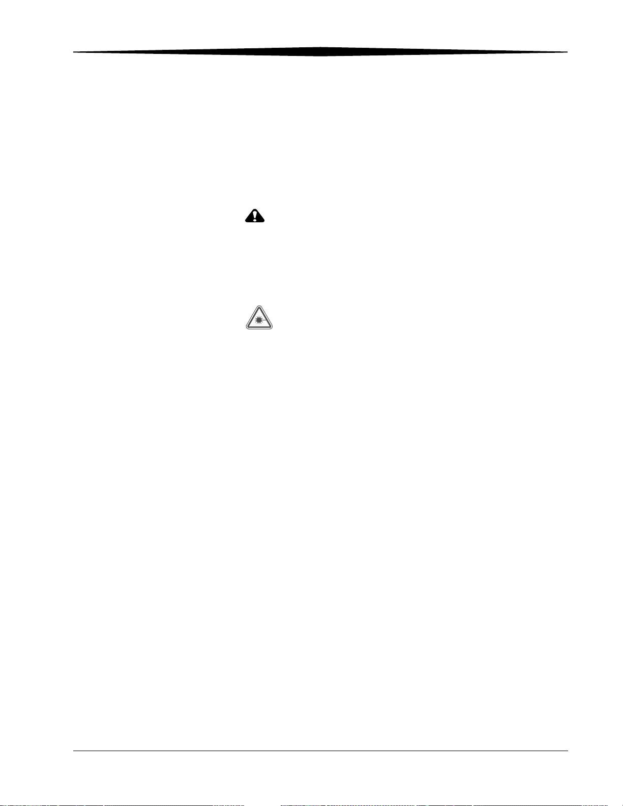
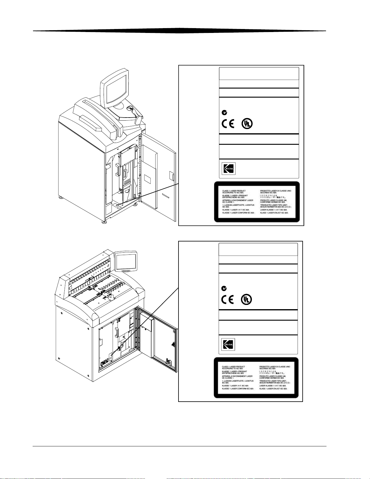
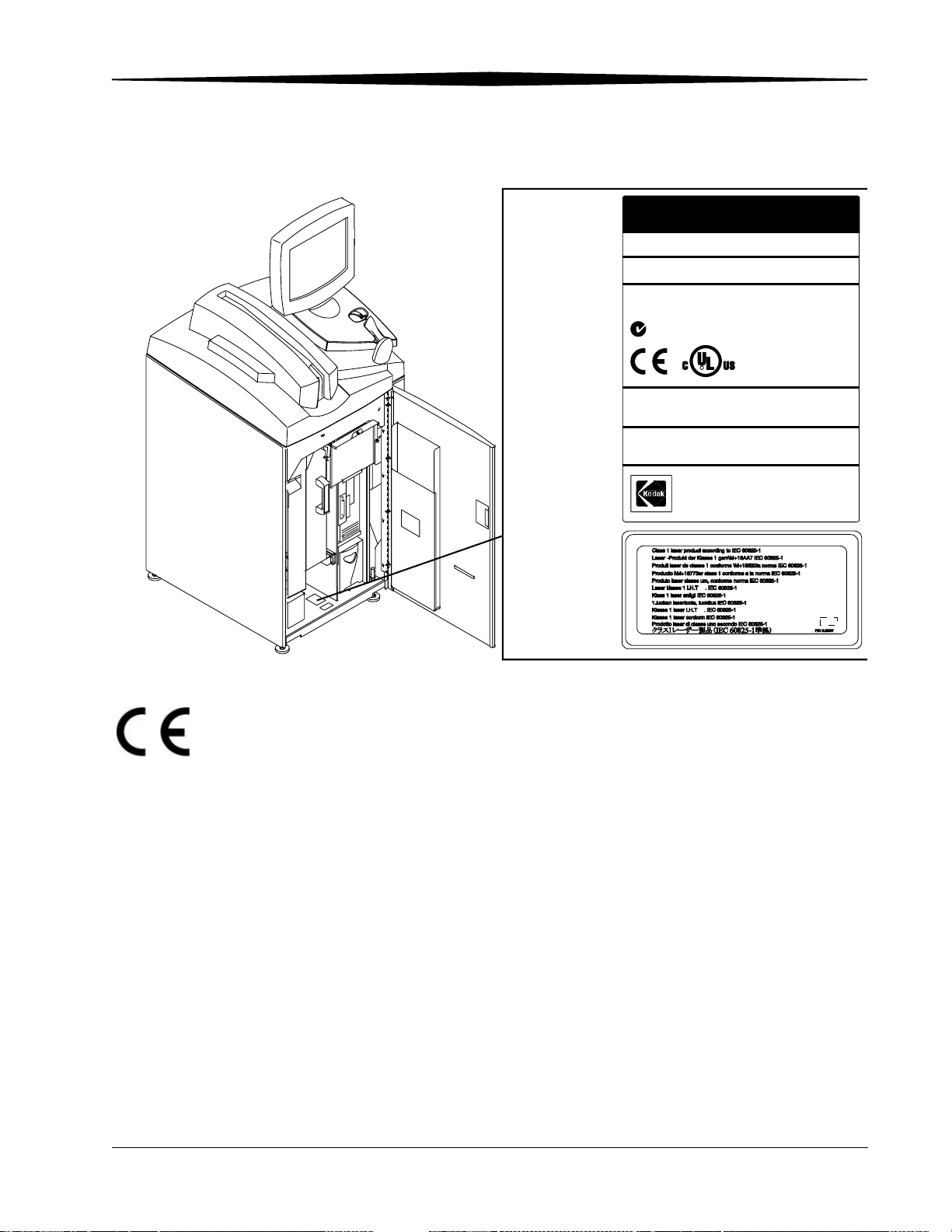
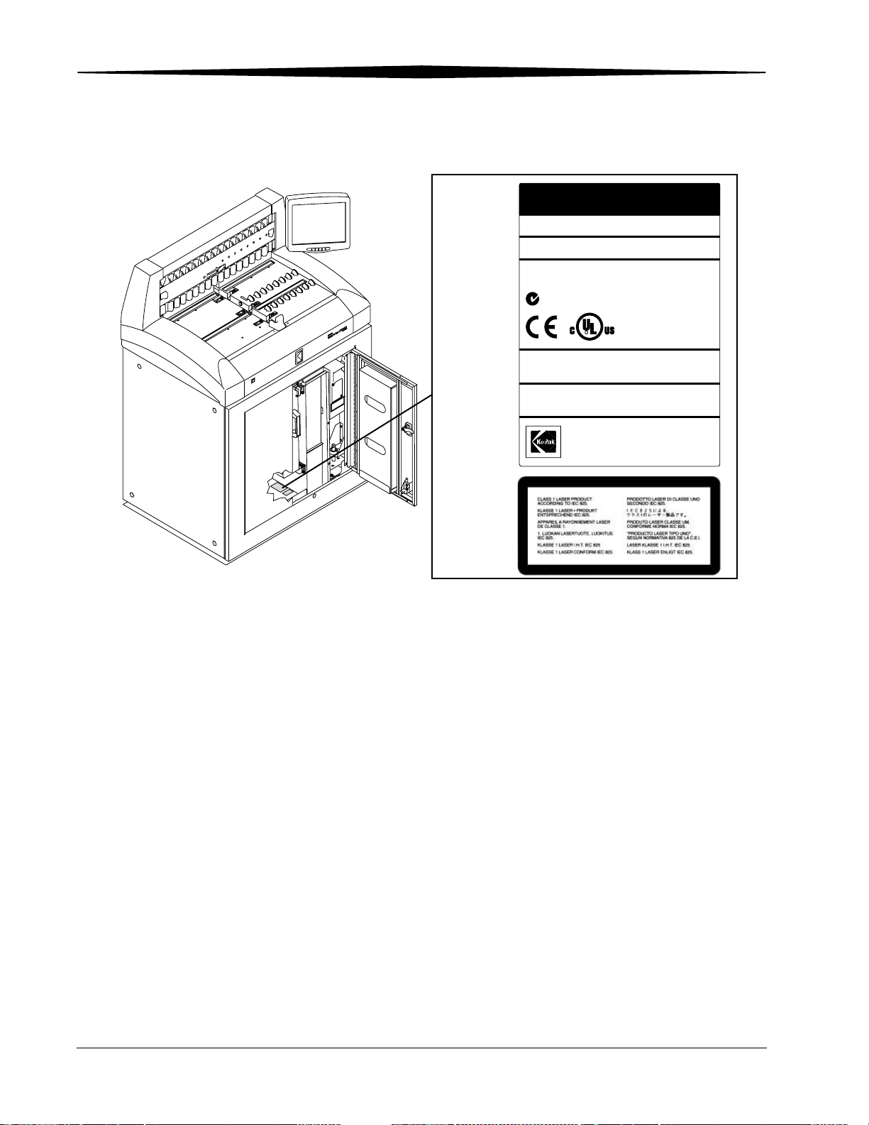
LASER WARNING:
This equipment uses a visible red laser. Laser radiation will be present
when the machine is opened with the side and back panels removed
and the interlocks defeated. Avoid direct exposure to the laser beam.
This product is a Class 1 Laser product. This product complies with DHHS
regulation 21 CFR Chapter I Subchapter J and IEC/EN 60825-1.
CLASS 1 LASER PRODUCT.
CLASS I EQUIPMENT.
INTERNALLY POWERED EQUIPMENT.
INTENDED FOR CONTINUOUS OPERATION.
ACCEPTABLE FOR INCIDENTAL OR CASUAL CONTACT WITH THE PATIENT.
PRODUCT IS PROVIDED WITH ORDINARY PROTECTION AGAINST THE
HARMFUL INGRESS OF WATER.
PRODUCT IS NOT SUITABLE FOR USE IN THE PRESENCE OF A FLAMMABLE
ANESTHETICS MIXTURE WITH AIR OR WITH OXYGEN OR WITH NITROUS
OXIDE.
June 3, 2003 1F3742 1-1
Page 12

Safety and Related Information
EUROPEAN MARKETS only:
This device is Class I, Type B medical equipment as defined by EN 60 601-1.
AUTHORIZED REPRESENTATIVE:
Manager, Product Safety, Kodak AG; Hedelfingerstr. 54-56, 70327 Stuttgart,
GERMANY.
This equipment has been tested and found to comply with the limits for a
Class A digital device, pursuant to part 15 of the FCC rules. These limits are
designed to provide reasonable protection against harmful interference when
the equipment is operated in a commercial environment. This equipment
generates, uses and can radiate radio frequency energy and, if not installed
and used in accordance with the instruction manual, may cause harmful
interference to radio communications. Operation of this equipment in a
residential area is likely to cause harmful interference in which case the user
will be required to correct the interference at his own expense.
The use of accessory equipment not complying with the equivalent safety
requirements of this equipment may lead to a reduced level of safety of the
resulting system. Consideration relating to the choice shall include:
• Use of the accessory in the patient vicinity.
• Evidence that the safety certification of the accessory has been
performed in accordance to the appropriate IEC 950 and/or IEC 601-1
and/or IEC 601-1-1 harmonized national standard.
CAUTION:
The small footprint and specifications of the CR 800/850
Systems allow for flexibility in placement of the unit, including
in the exam room. When installed in this manner, scatter
radiation from the x-ray system may cause image artifacts in
two scenarios:
• When CR cassettes are stored in the exam room.
Precaution: CR cassettes should not be stored in the exam room or
kept in the exam room during individual patient studies.
• When an exposed CR cassette is being scanned by the CR 800/850
System in the exam room during a subsequent x-ray exposure.
Precaution: The potential exists for artifacts if one cassette is being
processed while a second cassette is being exposed. If you experience
image artifacts, we suggest you discontinue simultaneous exposing
and processing of CR cassettes.
1-2 1F3742 June 3, 2003
Page 13

Safety and Related Information
CAUTION:
Kodak DirectView CR Cassettes contain lead. Disposal of
components that contain lead may be regulated due to
environmental conditions. For disposal or recycling
information, contact your local authorities or visit the
Electronics Industry Alliance web site at http://www.eiae.org.
CAUTION:
The UPS battery must be replaced by a Kodak authorized
Service Provider. The UPS battery contains lead and poses a
hazard to the environment and human health if not disposed of
properly. Due to the toxicity of lead, the US EPA’s Resource
Conservation and Recovery Act (RCRA) and state
solid/hazardous waste authorities consider a spent lead-acid
battery a regulated waste. Treat this battery as a hazardous
waste if it is not recycled. A recycling infrastructure is widely
available in the US to manage this battery type.
CAUTION:
This product contains mercury. Disposal of components
containing this material may be regulated due to
environmental considerations. For disposal or recycling
information, please contact your local authorities or visit the
Electronics Industry Alliance Web site at http://www.eiae.org.
The information contained herein is based on the experience and knowledge
relating to the subject matter gained by Eastman Kodak Company prior to
publication. No patent license is granted by this information. Eastman Kodak
Company reserves the right to change this information without notice and
makes no warranty, express or implied, with respect to this information.
Kodak shall not be liable for any loss or damage, including consequential or
special damages, resulting from the use of this information, even if loss or
damage is caused by Kodak's negligence or other fault.
June 3, 2003 1F3742 1-3
Page 14
Safety and Related Information
H177_0011HC
KODAK
SERVICE
CODE
MANUF
100-127V~ 50/60 Hz 10A
200-240V~ 50/60 Hz 5A
THIS
SUBCHAPTER J.
CER
CODE / CER
DE L’ELECTRICITE SEULEMENT.
DirectView CR800 system
SERIAL
3519
NUMBER
ACTURED:
N137
MEDICAL ELECTRICAL EQUIPMENT
I
S
F
S
I
E
A
L
C
C
25Y
PRODUCT
TIFIED ONLYTO CANADIAN ELECTRICAL
TIFIE EN VER
CLASSIFED BY UNDERWRITERS
D
LABORATORIES INC. WITH RESPECT TO
ELECTRICAL SHOCK, FIRE, MECHANICAL
US
AND OTHER SPECIFIED HAZARDS ONLY,
IN ACCORDANCE WITH UL 2601-1 AND
CAN-CSA C22.2 No. 601.1.
A
COMPLIES
WITH
TU DU CODE CANADIAN
21
CFR
Made in U.S.A. by
EASTMAN KODAK COMPANY
Rochester, NY 14650
CHAPTER I,
5E3348
H187_0001HC
KODAK
SERVICE
3520
CODE
MANUF
ACTURED:
N137
PRODUCT
THIS
SUBCHAPTER J.
TIFIED ONL
CER
CODE / CER
DE L’ELECTRICITE SEULEMENT.
DirectView CR900 system
SERIAL
NUMBER
10AHz 50/60 100-127V~
L
C
C
25YA
TIFIE EN VER
Made in U.S.A. by
EASTMAN KODAK COMPANY
Rochester, NY 14650
5AHz50/60 200-240V~
MEDICAL ELECTRICAL EQUIPMENT
I
S
F
S
I
E
A
CLASSIFED BY UNDERWRITERS
D
US
IN ACCORDANCE WITH UL 2601-1 AND
CAN-CSA C22.2 No. 601.1.
21
WITH
COMPLIES
CANADIAN ELECTRICAL
OTY
TU DU CODE CANADIAN
CHAPTER I,
CFR
TORESPECT WITH INC. TORIES LABORA
MECHANICALFIRE, SHOCK, ELECTRICAL
3H9506
,YONLHAZARDS SPECIFIED OTHER AND
1-4 1F3742 June 3, 2003
Page 15
Safety and Related Information
H194_0024HC
KODAK
CODE
MANUFACTURED:
100-127V~ 10A
COMPLIES WITH 21 CFR 1040.10 AND 1040.11
EXCEPT FOR DEVIATIONS PURSUANT TO LASER
NOTICE NO. 50, DATED JULY 26,2001.
CERTIFIED ONLY TO CANADIAN ELECTRICAL
CODE / CERTIFIE EN VERTU DU CODE CANADIAN
DE L’ELECTRICITE SEULEMENT.
DirectView CR 850 system
SERIALSERVICE
4825
NUMBER
Hz
50/60
Hz200-240V~
N137
50/60
S
A
L
C
R
5A
I
S
F
I
E
D
WITH RESPECT TO ELECTRICAL SHOCK,
FIRE AND MECHANICAL HAZARDS ONLY
IN ACCORDANCE WITH UL 2601-1,
CAN/CSA C22.2 No. 601.1.
Made in U.S.A. by
EASTMAN KODAK COMPANY
Rochester, NY 14650
MEDICAL EQUIPMENT
25YA
1F4335
June 3, 2003 1F3742 1-5
Page 16
Safety and Related Information
H196_0100HC
KODAK
SERVICE SERIAL
CODE
DirectView CR 950 system
4826
NUMBER
MANUFACTURED:
50/60
200-240V~ Hz
COMPLIES WITH 21 CFR 1040.10 AND 1040.11
EXCEPT FOR DEVIATIONS PURSUANT TO LASER
NOTICE NO. 50, DATED JULY 26,2001.
CERTIFIED ONLY TO CANADIAN ELECTRICAL
CODE / CERTIFIE EN VERTU DU CODE CANADIAN
DE L’ELECTRICITE SEULEMENT.
50/60
N137
A
L
C
Made in U.S.A. by
EASTMAN KODAK COMPANY
Rochester, NY 14650
10A100-127V~
Hz
5A
I
S
F
S
I
R
MEDICAL EQUIPMENT
E
D
WITH RESPECT TO ELECTRICAL SHOCK,
FIRE AND MECHANICAL HAZARDS ONLY
IN ACCORDANCE WITH UL 2601-1,
CAN/CSA C22.2 No. 601.1.
25YA
1F5241
1-6 1F3742 June 3, 2003
Page 17

Health and Safety Compliance
The CR 800/CR 900 Series Systems were examined for compliance and have
classifications and licenses as follows:
CR 800/900 Systems U. S. A.
47 CFR Part 15, Sub B, Class A
UL 2601-1 Medical Electrical Equipment 2nd Edition
Canada
CAN/CSA C22.2 No. 601.1-M90 - Medical Electrical Equipment
CAN/CSA 22.2 No. 601.1S1-94 Supplement No. 1-94 to Medical Electrical
Equipment (R1999)
CAN/CSA 22.2 No. 601.1B-90 - Amendment 2 to Medical Electrical Equipment
ICES-003 Issue 3, Class A ITE Emissions
Safety and Related Information
International
IEC 60601 - 1: 1988, +A1 (1991), + A2(1995) Medical Electrical Equipment
IEC 825-1 - (1993) Safety of Laser Products
EN 60601-1-2:1993 Medical Electrical Equipment Electromagnetic
Compatibility
EN 55011: 1998 ISM Emissions, Group 1 Class A
EN 61000-4-2: 1995 Electrostatic Discharge immunity test
EN 61000-4-3:1997 Radiated, Radio-Frequency, electromagnetic field
immunity
EN 61000-4-4: 1995 Electrical Fast Transient/burst immunity
EN 61000-4-5: 1995 Surge immunity
EN 61000-4-6: 1996 Immunity to conducted disturbances
EN 61000-4-11: 1995 Voltage dips, sags, interrupts
EN 61000-3-2: 1995: Limits for harmonic current emissions
EN 61000-3-3: 1995 Flicker
WARNING:
This is a class A product. In a domestic environment this
product may cause radio interference in which case the user
may be required to take adequate measures.
June 3, 2003 1F3742 1-7
Page 18

Safety and Related Information
CR 850/950 Systems U. S. A.
47 CFR Part 15, Sub B, Class A
UL 2601-1 Medical Electrical Equipment 2nd Edition
Canada
CAN/CSA 22.2 No. 601.1-M90 - Medical Electrical Equipment (R2001)
CAN/CSA 22.2 No. 601.1S1-94 - Supplement No. 1-94 to Medical Electrical
Equipment (R1999)
CAN/CSA 22.2 No. 601.1B-90 - Amendment 2 to Medical Electrical Equipment
(R2002)
ICES-003 Issue 3, Class A ITE Emissions
International
IEC 60601 - 1: 1988, +A1 (1991), + A2(1995)Medical Electrical Equipment
IEC 60825 - 1:1993 + A1:1997 + A2:2001 Safety of Laser Products
EN 60601-1-2:1993 Medical Electrical Equipment Electromagnetic
Compatibility
EN 55011: 1998 ISM Emissions, Group 1 Class A
EN 61000-4-2: 1995 Electrostatic Discharge immunity test
EN 61000-4-3: 1997 Radiated, Radio-Frequency, electromagnetic field
immunity
EN 61000-4-4: 1995 Electrical Fast Transient/burst immunity
EN 61000-4-5: 1995 Surge immunity
EN 61000-4-6: 1996 Immunity to conducted disturbances
EN 61000-4-11: 1995 Voltage dips, sags, interrupts
EN 61000-3-2: 1995: Limits for harmonic current emissions
EN 61000-3-3: 1995 Flicker
WARNING:
This is a class A product. In a domestic environment this
product may cause radio interference in which case the user
may be required to take adequate measures.
Acoustic Noise Emission Information
Operator position Sound Pressure Levels (LA)
Standby <70 dB(A)
Operate <70 dB(A)
Tested per DIN 45635, ANSI S12.10-1985, ISO 7779.
1-8 1F3742 June 3, 2003
Page 19

Safety and Related Information
Remote Operations Panel
U.S.A.
UL 1950 Safety for Information Technology Equipment
Canada
CAN/CSA C22.2 No. 950-95 Safety for Information Technology Equipment
International
EN 60950:1992 Safety for Information Technology Equipment (with
Amendments A1, A2, A3, A4, and A11)
EN 55011:1998 ISM Emissions, Group 1 Class A
EN 60601-1-2: 1993 Medical Electrical Equipment Electromagnetic
Compatibility
EN 61000 -3-2:1995 Powerline Harmonics
EN 61000 -3-3:1995 Flicker
EN 61000 -4-2:1995 ESD
EN 61000 -4-3: 1997 RF immunity
EN 61000 -4-4: 1995 EFT
EN 61000 -4-5: 1995 Surge immunity
EN 61000 -4-6: 1996 Conducted immunity
EN 61000 -4-11: 1995 Voltage dips, sags, interrupts
WARNING:
This is a class A product. In a domestic environment this
product may cause radio interference in which case the user
may be required to take adequate measures.
June 3, 2003 1F3742 1-9
Page 20
Safety and Related Information
User Guide Conventions
Special Messages The following special messages emphasize information or indicate potential
risks to personnel or equipment.
NOTE: Notes provide additional information, such as expanded
explanations, hints, or reminders.
IMPORTANT: Important notes highlight critical policy information that
affects how you use this guide and this product.
CAUTION:
Cautions point out procedures that you must follow precisely
to avoid damage to the system or any of its components, loss of
data, or corruption of files in software applications.
WARNING:
Warnings identify procedures that you must follow
precisely to avoid injury to yourself or others.
LASER WARNING:
Laser warnings warn personnel that access to laser radiation is
possible and all personnel must avoid direct exposure to the beam.
Typeface Conventions
Boldface type represents buttons or selections that you make on the touch
screen and to identify screen names.
1-10 1F3742 June 3, 2003
Page 21

2
Overview
Product Description
The Kodak DirectView CR 800/CR 900 Series systems process and produce
digital images directly from latent images captured on storage phosphor
screens. You can reproduce, reprocess, and distribute images to other output
and storage devices.
The CR Systems manage patient and examination information associated with
the captured and stored images. They can interface with a PACS Broker such
as Mitra to obtain patient demographic data from the site HIS/RIS system. The
data is sent to the CR System where it is associated with the proper image.
You can use the CR System to:
• Read images on a phosphor screen using conventional X-ray generators.
• Modify images and change image orientation.
• Enter examination and patient information using the Kodak DirectView
Remote Operations Panel (ROP), the bar code scanner, or the touch
screen monitor.
• Correct erroneous patient or examination information.
• Store images that have incomplete patient or study data until the
required data is added and the image is accepted.
• Create collections of related images and data (a Study).
• Send exams to DICOM storage devices, physician’s diagnostic viewing
stations, and DICOM laser imagers.
The CR 900/950 System is designed for use as a centralized processing unit
serving multiple exposure rooms in conjunction with the Kodak DirectView
Remote Operations Panel (ROP). See page 10-10 for information on using
the ROP.
June 3, 2003 1F3742 2-1
Page 22
Overview
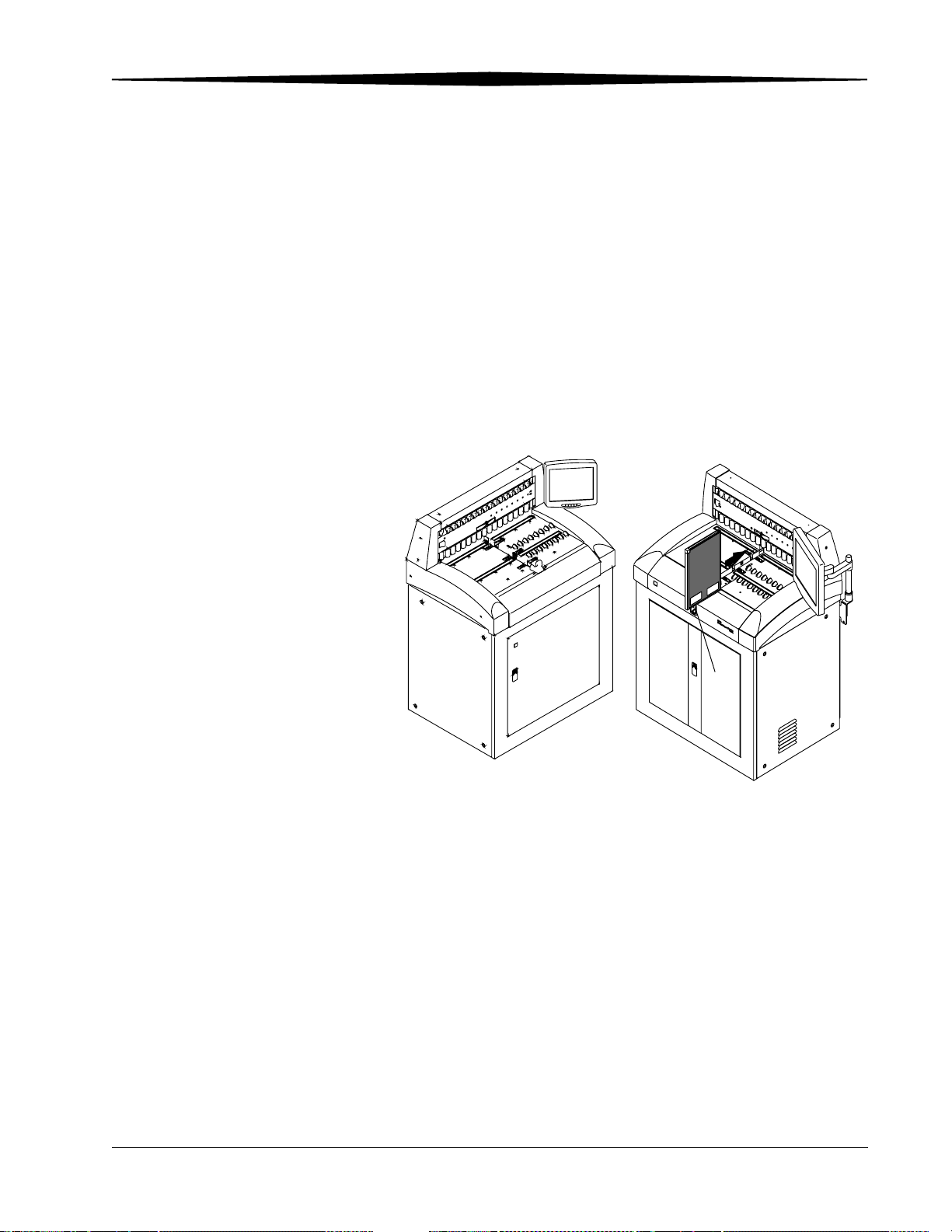
CR 800/850 System Components
The Kodak DirectView CR 800/850 System components include:
• Internal Computer
• Touch screen monitor
• Cassette feed slot
• Bar code scanner
• Internal Uninterruptible Power Supply (UPS)
The CR 800/850 System loads a single storage phosphor cassette, permits
automatic scanning of the phosphor screen, and produces an image. You
place the cassette into the cassette feed slot for scanning. Once the image is
scanned and stored on the CR System, the cassette is erased and ejected.
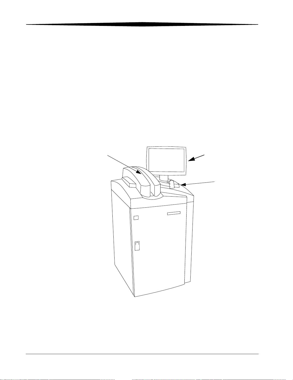
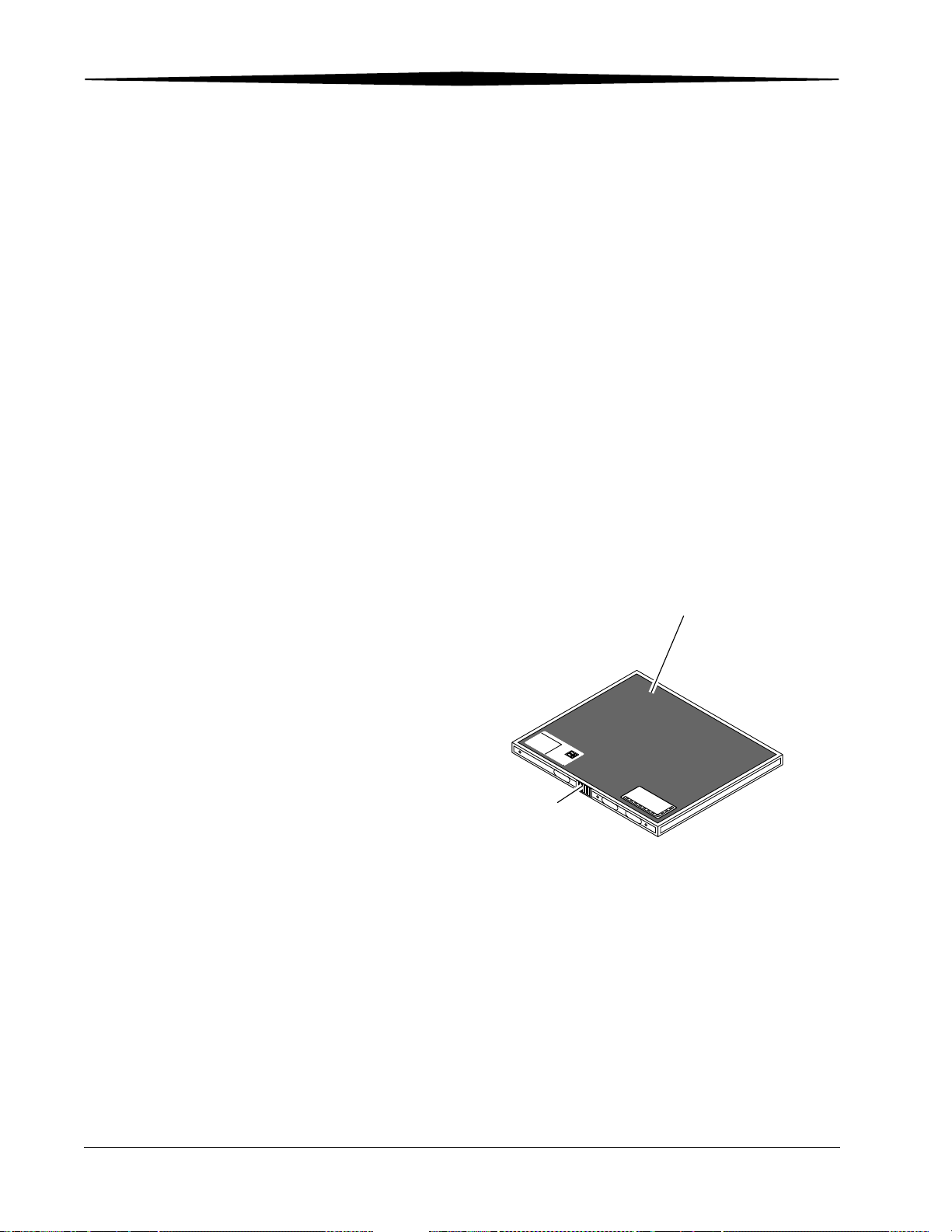
Cassette Feed
Touch Screen
Monitor
H177_0500GC
Kodak DirectView CR 800/850 System
Bar Code
Scanner
2-2 1F3742 June 3, 2003
Page 23
CR 900/950 System Components
The Kodak DirectView CR 900/950 System components include:
• Internal PC
• Touch screen monitor
• Cassette transport table for scanning
• Internal Uninterruptible Power Supply
The CR 900/950 System loads multiple storage phosphor cassettes, scans the
phosphor screen, and produces an image. You place the cassette into the
cassette transport table for scanning. Once the image is scanned and stored
on the CR System, the cassette is erased, ejected, and automatically moved so
the next cassette can be scanned.
Overview
T
u
b
e
S
i
d
e
Start
CR 900
CR 950
H187_0512GC
H196_0002GC
Kodak Directview CR 900 and CR 950 Systems
Cassette transport features include:
• Load and unload cassettes at eight positions
• Center-positioned scan slot
• Start and pause from the touch screen (CR 900 System only. CR 950 uses
mechanical Start button)
• Supports four standard cassette sizes
June 3, 2003 1F3742 2-3
Page 24
Overview
H177_2445AC
T
u
b
e
S
id
e
I
D
W
I
N
D
O
W
3
E
1
9
6
3
T
u
b
e
S
id
e
Cassette
Bar Code
H177_2445ACA
Touch Screen Monitor The touch screen monitor (touch screen) is mounted on top of the
CR 800/850 System. You can mount the touch screen monitor on the left side
or the right side of the CR 900/950 System or on the wall.
For the CR 900/950 System, in case of a network failure, use the touch screen
as a back-up system to enter patient demographic data, exam data, and
review images.
The monitor has an SGVA display with a 1024 x 768 pixel resolution.
Internal PC An internal PC, accessible from the front of the CR System, contains the
operating software for image processing and for communicating with external
network devices.
Cassettes Storage phosphor screens are mounted in standard size cassettes. You
perform patient exams the same way as when using conventional film
cassettes. Instead of processing film to develop the image, a laser in the CR
System scans the latent image on the phosphor screen and produces a digital
image. Cassettes are repeatedly exposed, and their screens erased and
reused. General Purpose (GP) cassettes have gray corners and High
Resolution (HR) cassettes are identified with black corners.
Typical Cassette
The CR Systems accept four standard cassette sizes:
• 18 x 24 cm
• 24 x 30 cm
• 35 x 35 cm
2-4 1F3742 June 3, 2003
• 35 x 43 cm
Page 25
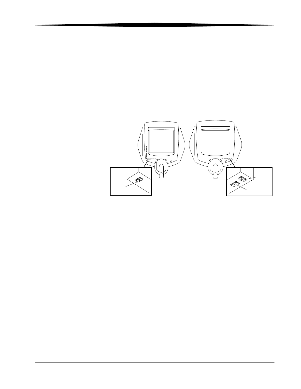
Remote Operations Panel
H177_1511AC
SWITCH
BRIGHTNESS
POWER
SWITCH
H177_1511ACA
The Kodak DirectView Remote Operations Panel (ROP) is a wall-mounted
touch screen where you can perform most CR System functions. Use the ROP,
with the bar code scanner, to enter patient, exam, or cassette (PEC) data, and
review and reprocess images and route the images to their destinations. All
Patient Exam Cassette (PEC) records and images are stored on the hard drive
of the CR System computer. You can query existing PEC records and images
stored in the CR System to review existing information. The ROP complies
with ITE type standards and is not suitable for patient contact.
Overview
POWER
SWITCH
Remote Operations Panel
Site Operating Configurations
Network Configuration
The CR Systems and ROPs require connection with external equipment to a 10
BaseT or 100 BaseT Ethernet network. All network communication is done in
accordance with DICOM-conforming digital imaging equipment. Physical
connections are via site-provided Category 5 cabling. In addition, the
customer must provide the Mitra Broker to enable access to the HIS/RIS
system.
You can configure each ROP to connect to a maximum of eight CR Systems.
H177_1521ACA
H177_1521AC
June 3, 2003 1F3742 2-5
Page 26
Overview
Kodak DirectView
CR 800 System
DICOM TCP/IP
CR 850 System
Mitra
HIS/RIS
PACS Broker
Destinations
CR 950 System
CR 950 System
Remote Operations Panel
Remote Patient
Data Entry Station
Kodak ArchiveManager
Medical Viewing Station
Kodak
Kodak
PACS Link
or
PACS Link
9410 Acquisition System
Medical Image Manager
and Automated Workflow
Digital Archive
Management System
Medical Viewing Station
Kodak DryView
8100 Laser Imager
CR 950 System
Kodak
PACS Link
DICOM Print Server
Kodak Ektascan
6_9000EC
Remote Operations Panel
ETHERNET
2180 Laser Printer
2-6 1F3742 June 3, 2003
Page 27

Workflow
Workflow Definitions
Overview
The CR System workflow consists of a series of tasks performed in sequence.
Definitions and a typical step-by-step workflow sequence are listed below.
Cassette ID Identification number on cassette.
Collimate To reduce the size of the X-ray beam by restricting
it, usually with lead shutters.
Destinations Locations on the network to which an image is sent.
Exam One or more images with the same associated
information.
Exam Information Data pertaining to the way the image was captured.
HIS Hospital Information System
Image A single picture.
Key Operator The person or persons designated by the
department manager to receive advanced training.
The Key Operator has the password for access to
password protected areas for changing defaults,
routing profiles, etc.
Patient Exam Cassette
(PEC) Record
Patient Information Demographic information that includes patient’s
Post Processing Any image re-processing or manipulation after the
RIS Radiology Information System
Storage Phosphor The phosphor crystal that captures and stores the
Study A collection of related images and data.
Worklist Management Enhances clinical workflow by importing patient
The demographic data and cassette ID that has
been tied together to create a record/image file.
name, date of birth, physician, etc.
initial image processing.
latent analog raw image data.
information and study information from an
information management system, eliminating
errors from manual entry.
NOTE: If you purchase the Kodak DirectView Remote Patient Data Entry
Software, you can collect patient demographic data at a computer.
June 3, 2003 1F3742 2-7
Page 28
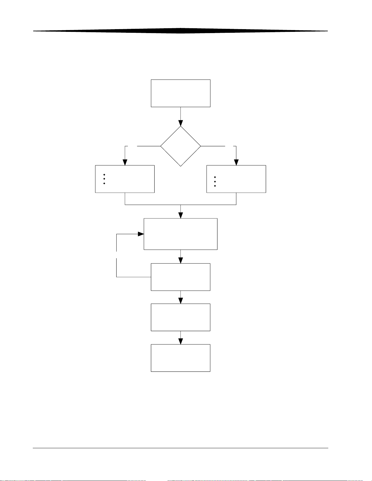
Overview
Workflow Diagram
Collect patient demographic
data.
YES
Enter Patient Data
Scan the Patient ID bar code.
Query the Local database.
Query the HIS/RIS
database.
Repeat as needed
HIS/RIS
Broker?
1. Scan the cassette bar code label.
2. Enter Exam data.
3. Touch Submit.
4. Position the Patient.
5. Collimate properly for best image quality.
6. Expose the cassette
Expose additional cassettes if
.
necessary.
Load the cassette(s)
in the CR System.
NO
Manually enter the Patient
data on the
ROP
CR System, or
Remote Patient Data
Entry Station.
Review and evaluate images.
If acceptable, send to destinations
and release patient.
H194_9000EC
IMPORTANT: For maximum throughput, accept images as soon as they
are available.
2-8 1F3742 June 3, 2003
Page 29
3
Operation and Main Menu
Starting the CR System
To turn on the CR System power:
1. Release the latch and open the front door.
2. Press and hold I/TEST on the UPS until you hear a beep, then release.
3. Check that the power LED on the computer illuminates and remains on.
4. If the Power LED is not on, press the Power button on the computer.
5. Close and latch the front door. The CR System will not initialize unless the
front door is closed.
6. Wait for the CR System to initialize. The Main Menu or the Login screen
appears.
PC
I/Test
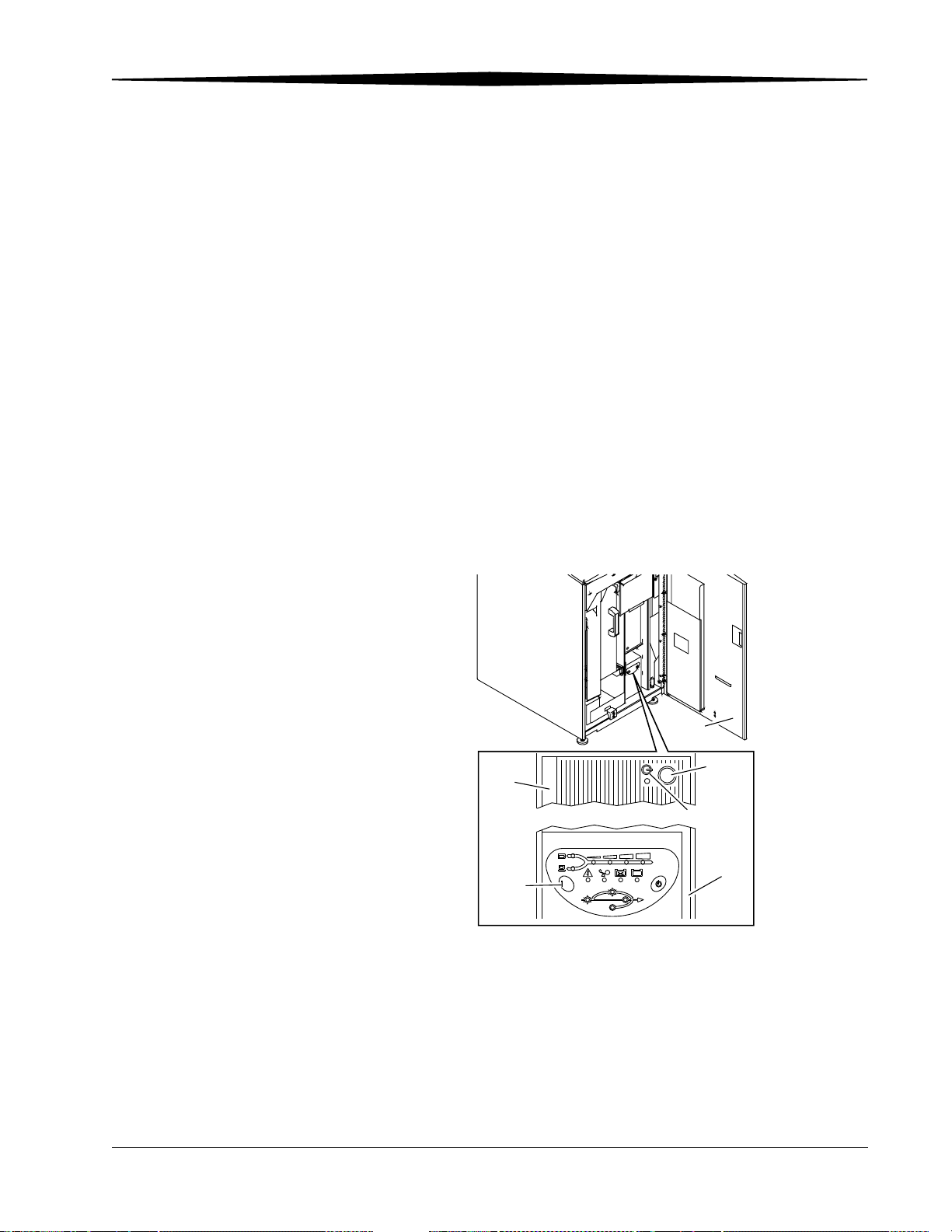
H177_0133GCA
H177_0133GC
/TEST
Line
On Battery
CR 800/850 System Front View
Bypass
T
S
E
T
/
Front
Door
Power
Button
Power LED
DC
BA
UPS
On Line
June 3, 2003 1F3742 3-1
Page 30
Operation and Main Menu
DCBA
Bypass
On Line
H187_0102GC
/TEST
Line
ABCD
Bypass
On Line
On Battery
H196_0003GC
/TEST
Line
On Battery
CR 900 and CR 950 Front Views
Logging on to the Operator Console (Option)
1. Enter your user name.
2. Enter your password.
3. Touch Login.
NOTE: A ROP can login to any CR System listed in the ROPs Link Screen if
you have an account on any CR System in the list.
Changing your Password
You can change the password you use to log in to the Operator Console.
1. At the Main Menu, touch Utility Menu.
2. Touch Change Password.
3. Enter your current password.
4. Enter your new password.
5. Enter your new password again.
6. Touch Save Changes.
Shutting down the CR System
To shut down the CR System power:
1. At the Main Menu, touch Utility Menu.
2. Touch System Shutdown and touch Yes. The CR System shuts down.
3-2 1F3742 June 3, 2003
Page 31

NOTE: The Operating System shuts down one minute after the CR System.
NOTE: If the touch screen locks up, see “Using the Touch Screen” on
Rebooting the System
To Reboot the system:
1. At the Main Menu, touch Utility Menu.
2. Touch System Shutdown and touch Reboot.
This method lets the system return to readiness quickly since it eliminates the
need for hardware warm-up.
Operation and Main Menu
The UPS shuts down two minutes after the CR System application.
page 3-7.
June 3, 2003 1F3742 3-3
Page 32

Operation and Main Menu
Power Failures
The CR System contains an Uninterruptible Power Supply (UPS) to protect the
system against an abrupt power loss.
If a power failure occurs, the UPS sustains system power to:
• complete all critical activities
• save present operating data, and
• shut down the Operating System.
If power is restored before the UPS battery charge drops to 25%, the system
resumes operation without interruption. However, once the battery level
drops to 25%, the system automatically shuts down.
In the event of a power loss, an error message appears within 30 seconds of
the power loss. For any image currently being routed, the system attempts to
complete the transmission. If there is not sufficient time to accomplish this,
the image is automatically transmitted once power is restored.
If a Cassette is in the load position at the time of automatic shutdown, the
system completes the scan, stores the raw image on the hard disk, and erases
the phosphor plate prior to the UPS shutdown.
Operating Modes
The CR System operates in two basic modes: (1) Pass-through mode and (2)
QA mode. The Key Operator, Applications Consultant, or Service Engineer
configures the mode of operation per the direction of the department
manager.
Pass-through Mode In Pass-through mode, the completed exam is processed and routed, typically
without stopping. When Pass-through mode is configured, a button appears
on the Scan Cassette screen next to the Start button. This button toggles
between Pause Pass-thru and Resume Pass-thru. You can temporarily
pause Pass-through mode by touching the button. To resume
Pass-through mode, touch . When the system distributes the image,
if necessary, you can recall the image for review and reprocessing.
QA Mode In the QA mode, the technologist must view and approve the image before
distributing it across the network.
3-4 1F3742 June 3, 2003
Page 33
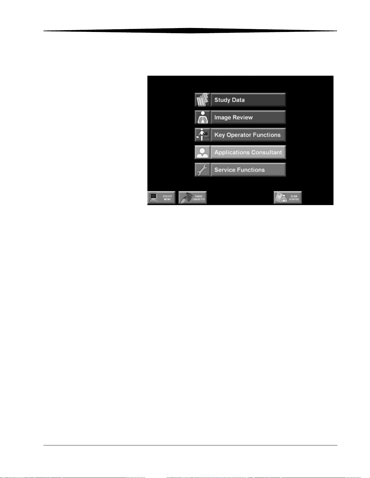
Main Menu
Operation and Main Menu
CR Main Menu
Main Menu Functions The function buttons on the Main Menu are:
• Study Data—enter patient data, create new studies, access worklists.
• Image Review—view all stored images, reprocess images.
• Key Operator Functions—set up and manage system configurations
(Accessed by Key Operator and Applications Consultant only).
• Applications Consultant—change Image Processing parameters, access
SMPTE Test Pattern.
• Service Functions—service the machine (Qualified Service personnel
only).
NOTE: The Key Operator Functions, Applications Consultant, and Service
Functions selections are only accessible by authorized personnel.
June 3, 2003 1F3742 3-5
Page 34

Operation and Main Menu
Main Menu Screen Navigation Buttons
When the Main Menu is displayed, these navigation buttons are active at all
times:
Name Description
Utility Menu Lets you shutdown the system, logout, and change
password (if configured for passwords), check
system status, release cassettes, clear pending
images, and restart the browser.
Erase Cassette Lets you erase an unwanted exposure from a
cassette.
Scan Status / Scan
Cassette
Additionally, if some images were not delivered or do not have patient
data associated with them, the following buttons may also appear:
• CR 800/850: Scan Cassette displays the scan
progress and the last image scanned.
• CR 900: Scan Cassette displays scan progress,
last image scanned, and the scan Start button.
• CR 950: Scan Cassette displays scan progress
and the last image scanned. The scan Start
button is removed from the monitor and
replaced by a mechanical button on the front of
the CR System.
Failed Delivery Alerts you when the system starts, or any time the
Main Menu is displayed, of any image that failed
to be delivered to the selected destinations. Touch
the button to display the images that were not
delivered.
This button does not appear if there are no failed
deliveries.
Unassigned Images Alerts you when the system starts, or at any time the
Main Menu is displayed, of unassigned images.
Touch the button to display the unassigned image
records.
This button does not appear if there are no
unassigned images.
3-6 1F3742 June 3, 2003
Page 35

Operation and Main Menu
Using the Touch Screen
The Key Operator calibrates the touch screen so that the target response is
accurate. See “Calibrate Touch Screen” on page 9-89. When the CR System or
ROP is turned on, the Main Menu appears.
To select a menu choice, touch the center of the button.
NOTE: Use only your finger when selecting buttons on the screen. Using hard
objects, such as pens or pencils can damage the surface of the touch
screen.
Navigation Buttons Use the Navigation buttons at the bottom of the screen to move from screen to
screen or to other functions. Some buttons display status information to alert
you to important operations or failed functions so you can respond if the
situation warrants immediate attention.
Main Menu and Back buttons
• Main Menu button—touch to return to the CR System Main Menu.
• Back button—touch to return to the previous screen.
NOTE: If the message Loading...appears, it means that the browser is loading
the Web page. If this message continues for an excessive period of
time, touch Main Menu to return to the Main Menu.
Error Messages Error Messages alert you to errors that occur during operation. Each Error
Message describes the cause of the error and instructions on how to clear it.
For more information, see “Error Messages” on page 7-1.
June 3, 2003 1F3742 3-7
Page 36
Operation and Main Menu
Virtual Keyboards
Virtual Keyboards let you enter data using the touch screen.
There are three keyboard types:
• an alphanumeric keyboard, similar to a standard keyboard, for entering
information
• a numeric keypad for entering numbers
• a button array for entering unique inputs for a particular field type
The Key Operator sets the local language for the virtual keyboards.
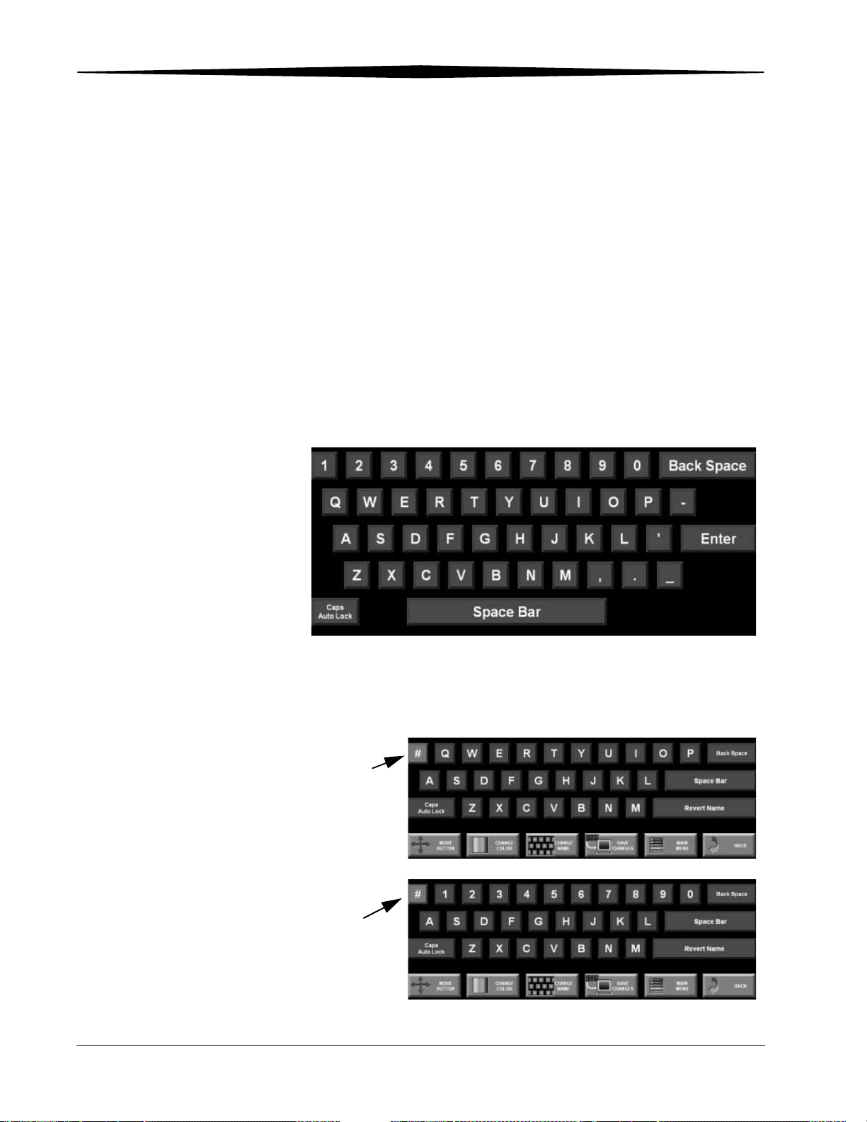
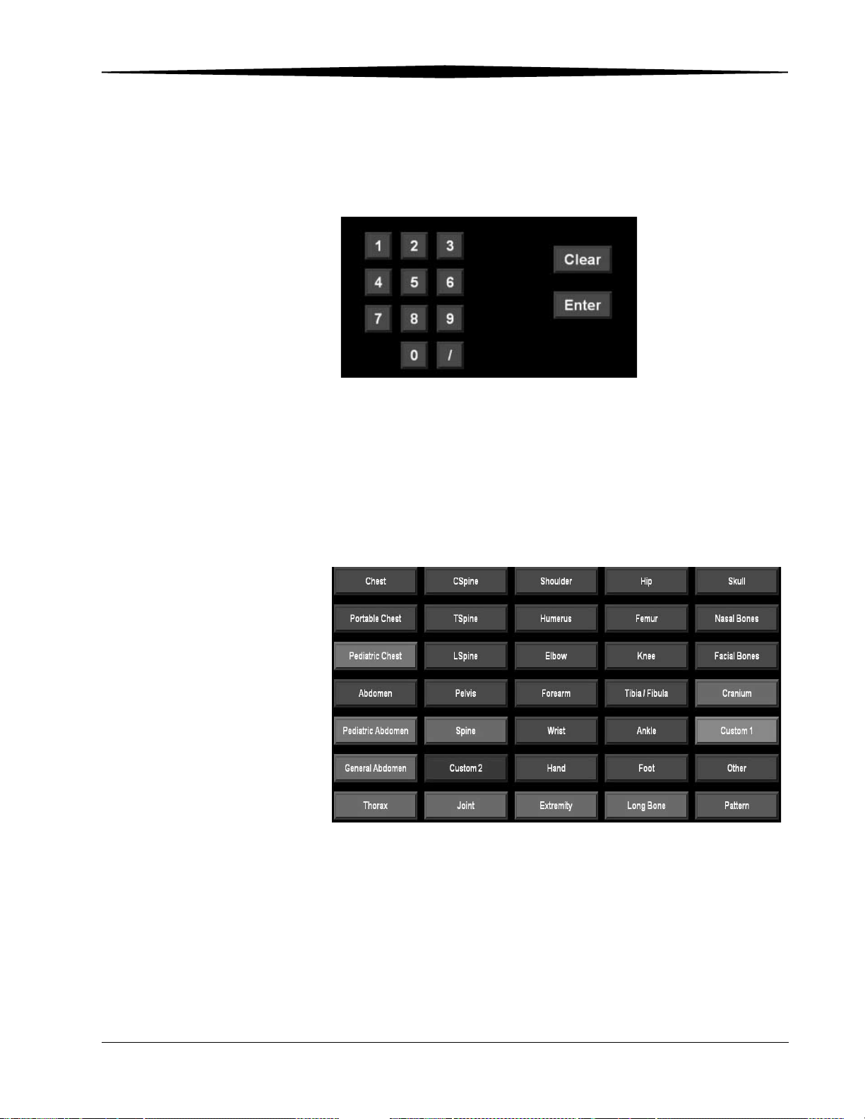
Standard Alphanumeric Virtual Keyboard
Touch each character you want to enter into a field and touch Enter. The
display returns to the previous screen or moves to the next empty field.
Standard Alphanumeric Virtual Keyboard
The # sign on the virtual keyboard acts as a toggle switch, so you can use
either alpha or numeric characters at any time.
Touch for
numeric
characters
Touch again for
alpha
characters
3-8 1F3742 June 3, 2003
Page 37
Operation and Main Menu
Standard Numeric Virtual Datepad
Touch each character you want to enter into a field and touch Enter. The
display returns to the previous screen or moves to the next empty field.
Standard Numeric Virtual Datepad
Special Keyboards There are special keyboards unique to the type of field selected. Touch a
button to enter the button name in the field. The Key Operator can set up
buttons for different lists of information. See “Changing Button Names, Colors,
and Position” on page 9-18 for more information.
For example:
Default Body Parts Virtual Keyboard
June 3, 2003 1F3742 3-9
Page 38
Operation and Main Menu
Entering Information into Data Fields
You can enter data manually using the touch screen or automatically using the
bar code scanner.
1. Touch the field you want to edit (the field turns blue). If you are using
the bar code scanner, skip to step 2.
2. Scan the bar code to transfer the data to the field or use the touch
screen. When you use the bar code scanner, the Accession Number,
Tech ID, Patient ID, and Cassette ID appear in the appropriate fields
automatically if they have been set up by the Key Operator. See “Bar Code
Configuration” on page 9-71.
NOTE: Not all fields can accept bar code input.
NOTE: Required fields are determined by the Key Operator and appear in the
input screen highlighted in yellow. Required fields must be filled in to
submit the record or send it to a mandatory destination. See
“Required Fields” on page 9-85.
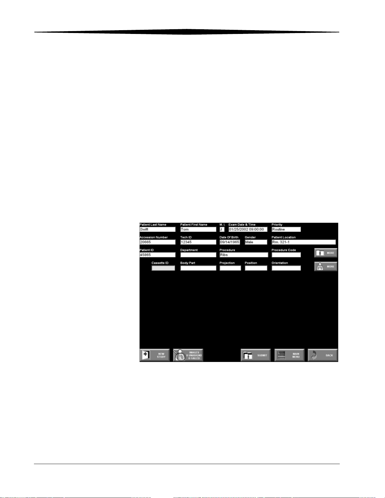
Patient Input Screen
3-10 1F3742 June 3, 2003
Page 39

4
Exam Data Entry
Manual Data Entry
NOTE: Always enter patient and exam information before scanning an
exposed cassette. This prevents the CR System from creating an
unassigned image. If an unassigned image is created, the CR System
lets you associate the image with the correct patient manually.
If you are searching for a patient that has already been submitted in the RIS,
see page 4-3 in this chapter to query for the patient.
Enter Patient and Exam information at the ROP or CR 800/CR 850 System. Use
the Patient Input Screen to enter the patient and exam information required.
The Patient Input Screen is available at the CR 900/CR 950 System for use in
case of network or ROP failure.
Complete the mandatory field highlighted in yellow to validate a PEC Record,
then complete the remaining optional information if it is available.
June 3, 2003 1F3742 4-1
Page 40

Exam Data Entry
Types of patient entries:
• New Patient—when information for a patient has never been entered in
the CR System or the HIS/RIS system.
• Trauma—quick data entry for emergency conditions.
• Existing Patient—when information for the patient already exists in the
CR System or the HIS/RIS system.
IMPORTANT: Always touch Submit after entering patient information
or selecting patient records. This reduces the risk of
creating unwanted, unassigned images.
4-2 1F3742 June 3, 2003
Page 41

Entering Patient Information
1. At the Main Menu, touch Study Data.
Exam Data Entry
You can now select New Patient, Trauma, or search the database for
an Existing Patient, or create a New Study. See the appropriate section.
2. Enter the information as indicated:
New Patient Touch New Patient and enter:
• Last name
• First name
• Middle initial
• Exam date and time
• Accession number
• Date of birth
• Gender
• Patient ID
• Referring Physician (use the More button)
• Department
• Patient location
June 3, 2003 1F3742 4-3
Page 42

Exam Data Entry
Trauma Patient Touch Trauma and proceed to “Entering Exam Information” on page 4-7.
The Key Operator can configure some fields to be filled in automatically.
NOTE: Your Key Operator may have configured a field with a “unique
number.” Each time you select a trauma patient, the number
increments to identify a new trauma patient.
Existing Patient You can enter as much or as little information as you like. The more
information you enter, the narrower the result is. If you do not enter
information, the entire patient list is returned.
1. Enter search criteria (use the bar code scanner if applicable).
– Enter desired search criteria
– Time field - list of filters to reduce query range including:
Today
Yesterday - Tomorrow
Past Week - Tomorrow
Unrestricted
– Study Status field - list of filters to reduce query range such as:
Scheduled
Started
Scheduled and Started
Completed
All
2. Touch Find Local or Find Remote.
– Find Local searches the CR System database.
– Find Remote is active when the Key Operator has configured for a
HIS/RIS; it searches the HIS/RIS system. The message “Waiting for
response” appears. If a match is not found for a query, adjust your
search criteria.
– Touch a Patient Name. Patient information automatically transfers to
the Patient Input Screen.
4-4 1F3742 June 3, 2003
Page 43

Patient Input Screen
Exam Data Entry
3. When a match is found, the Patient Worklist screen appears. The
entries are color coded. Colors are Key Operator configurable. The
default colors are:
• Scheduled > Blue
• Started >Black
• Completed >Dark Gray
Patient Worklist Screen
June 3, 2003 1F3742 4-5
Page 44

Exam Data Entry
New Study Touch New Study to create a new study using the patient information from an
existing study.
New Study
4-6 1F3742 June 3, 2003
Page 45

Entering Exam Information
After entering the patient information, enter the exam information into the
remaining fields on the Patient Input Screen. There are mandatory and
optional fields.
Exam Data Entry
Using Procedure Codes and Procedure Mapping
How you enter exam information depends on the way your system is
configured.
If you are using Procedure Codes and Procedure Mapping, the image icons
associated with a procedure (study) are predefined and appear automatically
once the Patient Input screen is displayed with the correct patient
information.
For each image in a procedure:
1. Touch an image icon to select it. The image is highlighted in green.
2. Manually enter or use the barcode to enter the cassette ID.
NOTE: If you are not using Procedure Codes and Procedure Mapping, you
must define the images associated with every procedure. To do this,
touch the body part field, select the appropriate body part then do the
same with projection. Touch Submit and the image icon appears.
June 3, 2003 1F3742 4-7
Page 46

Exam Data Entry
Mandatory Exam Information
Use the virtual keyboard to enter the exam information if the bar code
scanner cannot read the bar code. The cassette ID field is mandatory.
• Cassette ID: Use the bar code scanner to scan the bar code. If you do
not enter the Cassette ID number, the image is unassigned. You will have
to assign the image to a patient. You can change all image and patient
data except cassette ID.
Cassette
3
6
9
1
E
3
W
O
D
N
I
W
D
I
e
id
Tube S
Bar Code
Tube Side
H177_2445ACA
H177_2445AC
Scanning the Cassette ID
4-8 1F3742 June 3, 2003
Page 47

Exam Data Entry
Optional Exam Information
• Body Part: If the Body Part field is incomplete, the default is used as
defined by the Key Operator.
• Projection: If the Projection field is incomplete, the default is used as
defined by the Key Operator.
• Position: How the patient is positioned for the exam.
• Orientation: Whether the cassette is used in portrait or landscape
orientation. The default orientation is portrait; selecting landscape
displays the image in landscape mode.
• Priority: If the printer supports STAT images, the image moves ahead of
other images in the print queue. Routine and Urgent have the same
priority1.
• Tech ID: Use the bar code scanner to scan the code. If the Tech ID bar
code is not available, use the virtual keyboard to enter the Tech ID.
• Date of Birth: Enter the patient’s date of birth.
• Gender: Touch the appropriate gender button.
• Procedure Name and Code: These fields can be completed via the
HIS/RIS system data, selected from the procedure list, or manually.
• More Patient Information button:
– Referring Physician
– Patient Comments
– Contrast/Bolus
• More Image Information button:
– kVp
– mAS
– Source to Image Distance
– Source to Patient Distance
– Image Comments
– Laterality
• Patient Location: Enter the patient location.
See Chapter 9, “Procedure Mapping (Option)” on page 9-24.
1. Printers such as the Kodak DryView 8100 Laser Imager or the Kodak DryView 8700 Laser
Imager may print images in the order they were scanned rather than by priority when the
CR System is configured to Pass-through Mode.
June 3, 2003 1F3742 4-9
Page 48

Exam Data Entry
Saving the Patient
and
Exam Information
After you have entered the patient and exam information, touch Submit. The
information is stored in preparation for the exam.
NOTE: After you scan the cassette, the image thumbnail replaces the cassette
icon to display the image.
4-10 1F3742 June 3, 2003
Page 49
5
Scanning, Viewing and Printing Images
Performing an Exam
The procedure for performing an exam using a phosphor screen is the same
as an exam using screen/film.
To perform an exam:
1. Select the proper size cassette.
2. Position the patient and the cassette.
– For landscape orientation, place the yellow stripe label at the top right
of the image when you position the patient.
Landscape Orientation
Portrait Orientation
– For portrait orientation, place the yellow stripe label at the top left of
the image when you position the patient.
June 3, 2003 1F3742 5-1
Page 50

Scanning, Viewing and Printing Images
NOTE: Proper orientation at exposure eliminates the need to flip or rotate
3. Set the exposure factors.
4. Expose the cassette.
5. Place the cassette into the CR reader for scanning.
NOTE: The image on an exposed storage phosphor screen degrades over
NOTE: For best results, be sure to collimate properly.
the image at the CR.
time. Although a scannable image may be present for a period up to
24 hours, best results are obtained when the image is scanned within
1 hour.
5-2 1F3742 June 3, 2003
Page 51
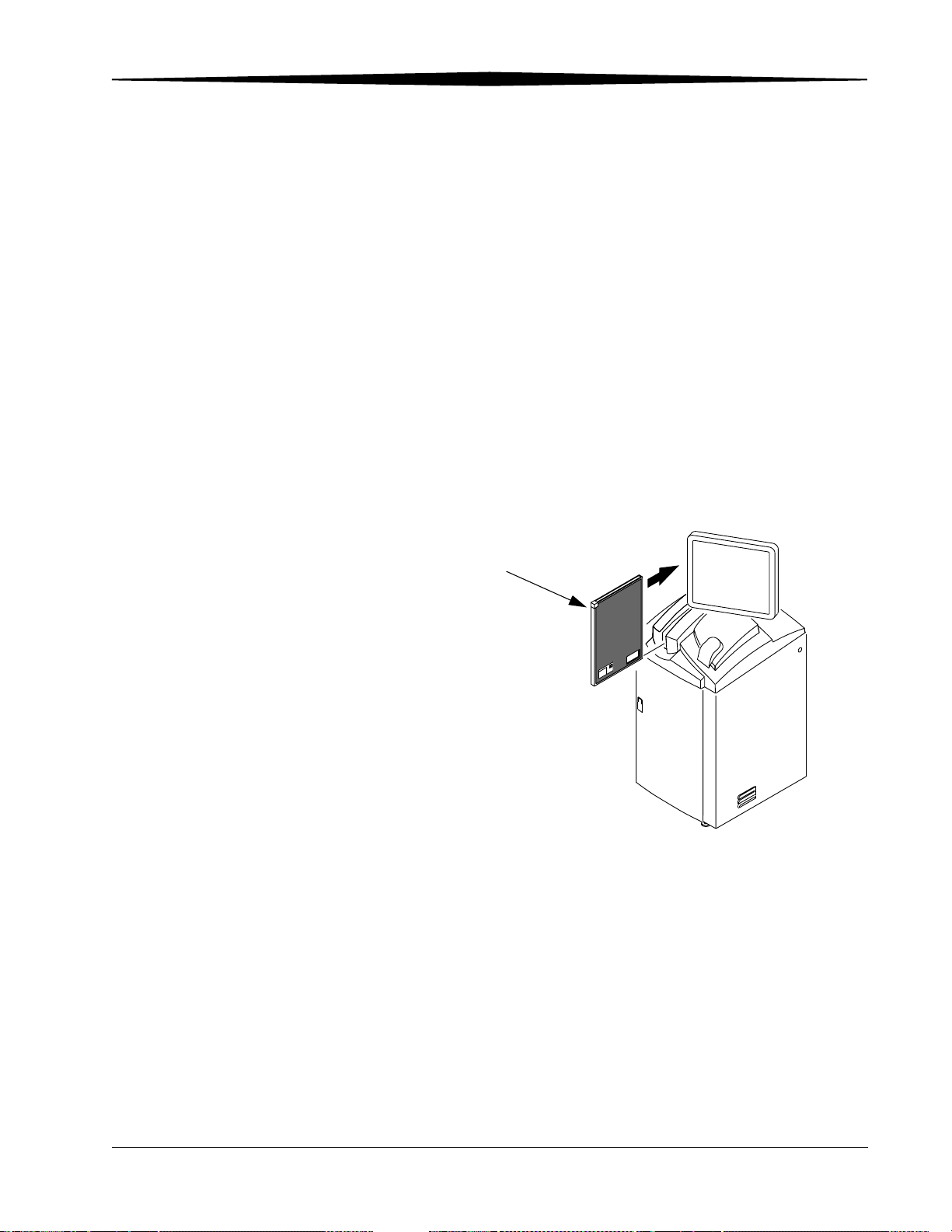
Scanning, Viewing and Printing Images
Loading Cassettes
CR 800/850 System 1. Place the cassette into the cassette feed slot at the top of the CR
800/850 System.
NOTE: Be sure that the tube side label faces to the right, and the yellow
corner of the cassette is always up and towards you. The relationship
of the label position and yellow corner differ depending on the
cassette size.
When the cassette is inserted into the CR 850 System, it is pulled into
scan position and scanning starts immediately. In the CR 800 System
insert the cassette until it touches the Stop mechanism. If the cassette is
not seated properly, an audible alarm sounds and an error message
appears on the touch screen.
2. After the cassette has been scanned, the system releases it automatically.
Remove the cassette from the cassette feed slot.
Yellow Corner
Tube Side
Inserting a Cassette in a CR 800/ CR 850 System
H177_0131GC
June 3, 2003 1F3742 5-3
Page 52

Scanning, Viewing and Printing Images
CR 900 System 1. Place exposed cassettes on the right side of the feed slot.
NOTE: Be sure that the tube side label faces to the right, and the yellow
corner of the cassette is always up and towards you.
2. Push the cassettes into one of the drive belt slots and then set it into the
transport mechanism. The cassette is perpendicular when loaded
properly. You can load up to eight cassettes of any size at one time.
3. From the Main Menu, touch Scan Status and touch Start to begin
scanning.
NOTE: When the cassette is pulled into the center slot, the phosphor screen
is extracted and scanning starts immediately. When scanning is
complete, the screen is erased and re-inserted into the cassette. The
cassette is ejected to the transport mechanism and moved to the left
as the next cassette is moved to the feed slot. You can now remove the
cassette and use it again.
You can touch Pause to stop the transport. If the unexposed cassette
area is filled with cassettes, the transport stops and a message displays
with instructions to remove cassettes from the unexposed cassette area.
NOTE: When the CR System scans the phosphor screen, it erases any
residual image before it places the phosphor screen back into the
cassette for re-use.
IMPORTANT: Place exposed STAT cassettes in the second slot to the right
of the center process slot. If there is already a cassette in
the second slot, remove it first. Do not load or remove
cassettes from Slot 1.
5-4 1F3742 June 3, 2003
Page 53
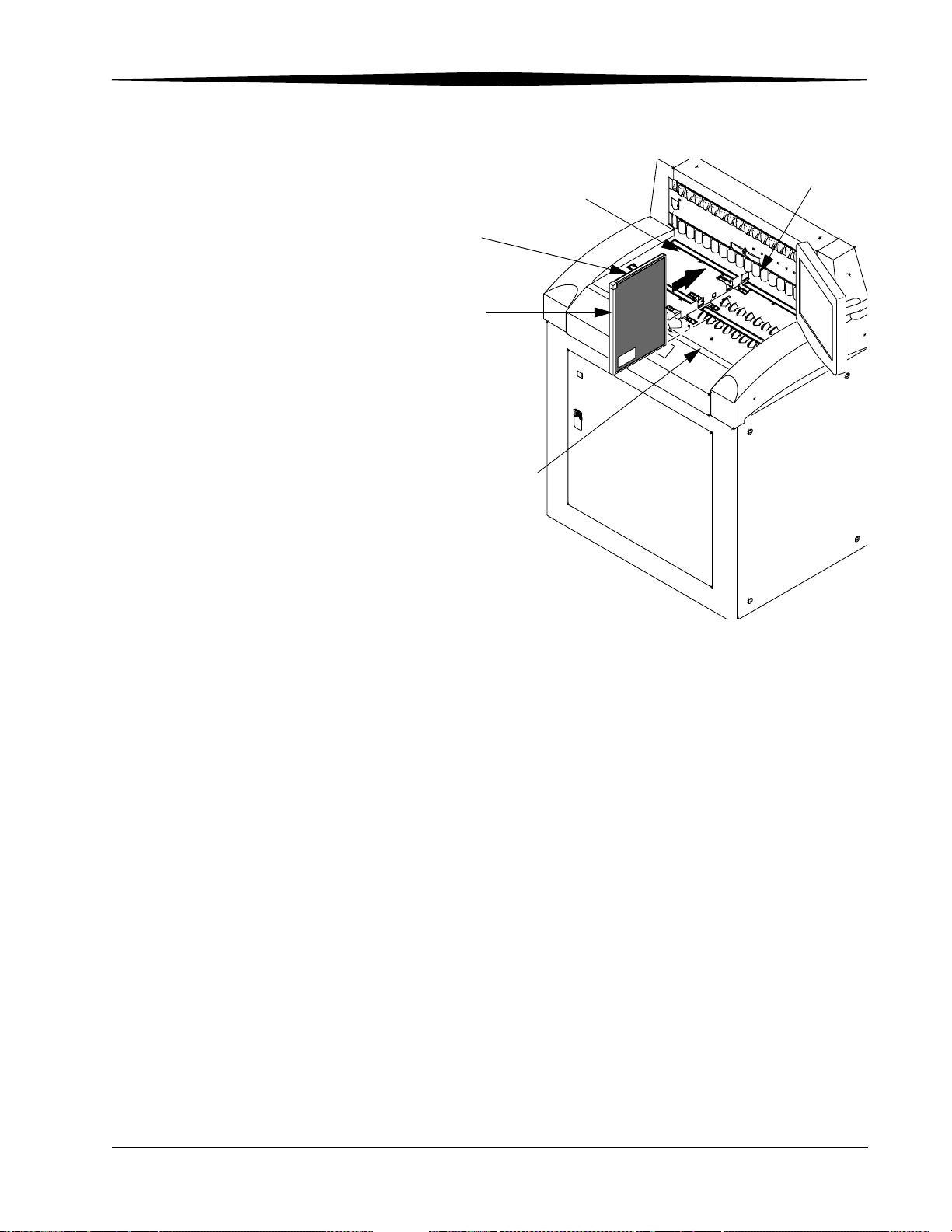
Unexposed Cassette
Area
Yellow Corner
Exposed Cassette Area
Scanning, Viewing and Printing Images
Slot 1
Drive Belt Slots
Tube S
ide
Loading a Cassette in a CR 900 System
June 3, 2003 1F3742 5-5
Page 54

Scanning, Viewing and Printing Images
CR 950 System 1. Place exposed cassettes on the right side of the feed slot.
NOTE: Be sure that the tube side label faces to the right, and the yellow
corner of the cassette is always up and towards you.
2. Push the cassettes into one of the drive belt slots and then set it into the
transport mechanism. The cassette is perpendicular when loaded
properly. You can load up to eight cassettes of any size at one time.
3. On the bridge of the machine, the Start button is green when the system
is ready to scan. Touch the Start button to begin scanning.
NOTE: When the cassette is pulled into the center slot, the phosphor screen
is extracted and scanning starts immediately. When scanning is
complete, the screen is erased and re-inserted into the cassette. The
cassette is ejected to the transport mechanism and moved to the left
as the next cassette is moved to the feed slot. You can now remove the
cassette and use it again.
The button turns orange while scanning. Push the button to Pause the
transport, and the button turns white. If the unexposed cassette area is
filled with cassettes, the transport stops and a message displays with
instructions to remove cassettes from the unexposed cassette area.
NOTE: When the CR System scans the phosphor screen, it erases any
residual image before it places the phosphor screen back into the
cassette for re-use.
IMPORTANT: Place exposed STAT cassettes in the second slot to the right
of the center process slot. If there is already a cassette in
the second slot, remove it first. Do not load or remove
cassettes from Slot 1.
5-6 1F3742 June 3, 2003
Page 55

Scanning, Viewing and Printing Images
Drive Belt Slots
Unexposed Cassette
Area
Yellow Corner
T
u
b
e
S
i
d
e
Exposed Cassette Area
Loading a Cassette in the CR 950 System
Slot 1
Viewing Images
Viewing an Image in Pass-through Mode
Viewing Images in
QA Mode
You can configure your system for two viewing modes: Pass-through Mode or
QA Mode.
If your system is configured in Pass-through Mode, the image is routed
immediately. To view the image, see “Reviewing Images” on page 5-13.
On the CR 900 / 950 System there is a button that toggles between Pause the
Pass-through mode or Resume the Pass-through mode.
If your system is configured in QA Mode, you review the image before you
route it to the selected destinations.
1. Scan the cassette and refresh the screen; a thumbnail image appears on
the Patient Input screen. Other images for the patient are displayed. If
there are too many images to display, Previous and Next buttons appear
so that you can access them.
2. Touch the thumbnail image to display the image for review.
June 3, 2003 1F3742 5-7
Page 56
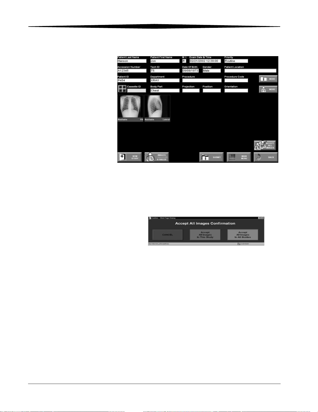
Scanning, Viewing and Printing Images
Scanned Image
3. If the images are acceptable, touch Accept All Images to send the
image(s) with the same Patient ID to the appropriate network
destinations. When all images are accepted, the button toggles to
End Study. Touch End Study to set the study to complete.
5-8 1F3742 June 3, 2003
Page 57
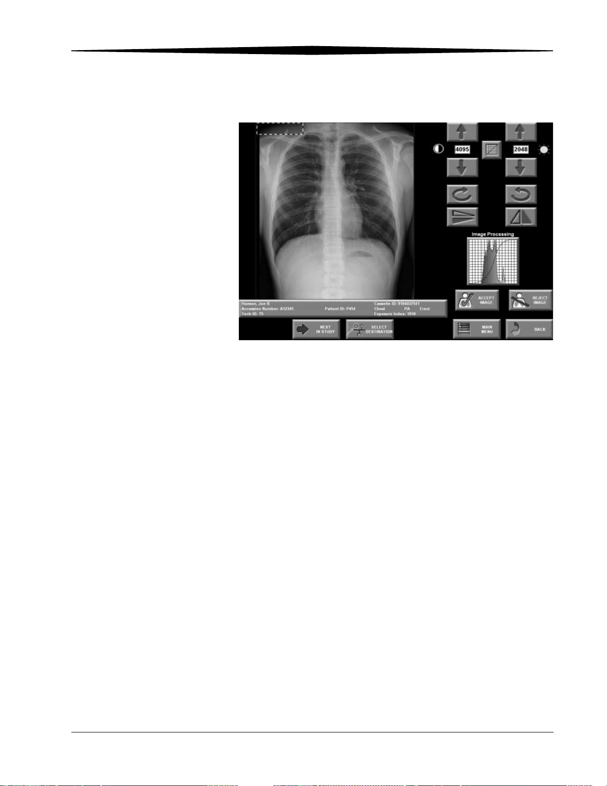
Scanning, Viewing and Printing Images
Image Viewer
4. To accept a single image after viewing, touch the thumbnail and touch
Accept Image on the Image Viewer screen.
5. If the image is unacceptable, touch Reject Image. A prompt confirms
that you want to delete the selected image. Touch Yes and the image is
deleted; the patient information stays on the CR System database.
If Reject Reason is activated:
• Touch a Reject Reason.
• Enter a Reject comment (optional).
• Touch Reject Image.
6. If further post-processing is required, see page 6-1.
June 3, 2003 1F3742 5-9
Page 58

Scanning, Viewing and Printing Images
Working with Images
Reprocessing Images You can modify images before you accept and route them. For information on
reprocessing previously delivered images, see “Image Processing” on
page 6-1. You can reprocess the displayed image in several ways, including
Edge Enhancement, Contrast, Brightness, etc.
Routing Images When you route images in QA mode, you send them to the destinations set up
by the Key Operator, or you can select specific destinations.
– Touch Accept Image to send the image to the destination set up by the
Key Operator.
– Or, touch Select Destination to send the image to specific destinations.
Destinations
To select a destination, move the cursor up or down with the arrows. Then
touch either the + or - to choose the number of copies to send to each. When
finished, touch Apply, then touch Accept Image to route the image.
5-10 1F3742 June 3, 2003
Page 59

Erasing Screens
Scanning, Viewing and Printing Images
WARNING:
Erasing deletes any image on the phosphor screen.
NOTE: Kodak recommends that you erase a phosphor screen if it has not
been used within the last week or if you suspect it has been exposed
to any X-radiation.
You can use the CR System to erase screens in cassettes without scanning an
image. The cassette erase feature is available only when the Cassette Erase
screen is displayed. To erase the phosphor screen in a cassette, at the CR
System Main Menu, touch Erase Cassette:
Cassettes Ready to be Erased on the CR 800/ CR 850
• CR 800/850—Insert the cassette. Erasing begins automatically.
• CR 900/950—Insert the cassettes and touch the Start button on the
touch screen.
The phosphor screen in the cassette is erased and released. If the Erase
screen is displayed and cassettes are not being erased, the screen saver
may be activated. If this happens, the system displays the Main Menu the
next time you touch the screen.
NOTE: The mechanical Start button on the front of the CR 950 is not active
during Erase mode.
June 3, 2003 1F3742 5-11
Page 60

Scanning, Viewing and Printing Images
Cassettes Ready to be Erased on CR 900 / CR 950
Erase Progress
5-12 1F3742 June 3, 2003
Page 61

Scanning, Viewing and Printing Images
Reviewing Images You can re-display images that have been accepted and routed for review,
modification, and reprocessing. When reviewing images, the procedures are
the same when viewing, modifying and routing an image.
1. At the Main Menu, touch Image Review.
Image Review
NOTE: An image that has been successfully delivered across the network
appears in the Delivered Images area.
2. Touch the appropriate button. View and modify the images as described
for image quality purposes.
June 3, 2003 1F3742 5-13
Page 62

Scanning, Viewing and Printing Images
Image Viewer
3. To assign a patient:
a. Under the image, touch Unassigned Image.
b. Find the correct name by doing a database query or touch
New Patient and use the virtual keyboard to enter the correct name.
Then touch Assign Image.
4. To assign a different patient:
a. Touch the bar under the image.
b. Touch Unassign Image.
c. Under the image, touch Unassigned Image.
d. Find the correct name by doing a database query or touch
New Patient and use the virtual keyboard to enter the correct name.
Then touch Assign Image.
5-14 1F3742 June 3, 2003
Page 63

Managing Images
Scanning, Viewing and Printing Images
As images are scanned, processed and routed, the CR System software keeps
track of the images and stores them based on their status. Sometimes an
image is not delivered properly or is unassigned. Use the Image Review
screen to display images by status for reviewing, reprocessing or resolving
problem images. At the Main Menu, touch Image Review. The following
image groups are available for selection:
Image Status Description
All Studies Displays all images that have not been delivered.
Need Approval Displays images that need to be
accepted/approved and sent across the network.
Unassigned Images Displays images not associated with a patient and
that have no demographic data. Refer to
“Unassigned Images” on the following page.
Failed Delivery Displays images that were not successfully
delivered to a network destination. Refer to
“Failed Delivery” on the following page.
Pending Delivery Images that are being routed but have not
reached all destinations.
Delivered Images Displays the images that have been successfully
delivered to selected destinations. These images
are sorted and displayed by Last Name
(ascending alphabetical order) and then by
Time.
June 3, 2003 1F3742 5-15
Page 64

Scanning, Viewing and Printing Images
Managing Failed Delivery Images
Managing Unassigned Images
Image Review
When an image is not successfully delivered to one or more of the selected
destinations, the text block next to the image is red. The image is stored as a
Failed Delivery image. To resolve Failed Delivery images:
1. Touch the image thumbnail to view the image.
2. Touch Redeliver Image. If delivery fails again, go to the Destination
screen and use the (-) to set the counter to 0 on the failing destination.
3. Select another destination and touch Redeliver Image.
4. If the problem continues, contact your Key Operator.
An image is stored as an Unassigned Image when it has not been associated
with a patient information record. This happens if the cassette is scanned
before the patient information is submitted with the proper cassette ID. The
record on the Image Review screen is orange when the image is unassigned.
To assign an image to a patient, you must first create a study:
1. At the Main Menu, touch Study Data.
2. Use the search criteria to find the patient for the new study.
3. Select the correct patient from the resulting patient list.
4. Touch New Study.
5. Enter the Study Data: Accession number, procedure code, etc.
6. Touch Submit.
7. At the Main Menu, touch Image Review.
5-16 1F3742 June 3, 2003
Page 65

Scanning, Viewing and Printing Images
8. Select the image you want to assign to the newly created study.
9. Touch the Patient Information bar.
10. Search for the patient for whom you created the study and select the new
study.
11. Touch Assign Image.
When the image is assigned, the record turns from orange to green.
June 3, 2003 1F3742 5-17
Page 66

Scanning, Viewing and Printing Images
Printing Images
There are three printing modes available with the CR System:
Print Mode Description
Best Fit The image is as large as possible without
exceeding True-size. No data is cropped.
a
Consistent Image Size The image is created at 92.5% of True-size. This
percentage is fixed and cannot be changed by
the technologist; no data is cropped.
Images from cassettes that are the same size as
film used by the printer may not print properly
if you are using the external text box . There are
not enough pixels available to print both the text
box and the image at 92.5%.
NOTE: For best results, do not use the
external text box with Consistent Image
Size print mode. Use the internal text
box. If you must use the external text
box, test all combinations at the site
before the equipment enters service.
True-size The image is the same size as the latent image
that existed on the phosphor screen when it was
scanned, within +/- 2%. This is equivalent to the
size of an image on film.
The CR System crops data from the edges of a
True-size image because the CR image is
typically larger than a printer can produce on a
comparable film size.
a. See Table: CR Image Minification Factors for Common Kodak Printers on
page 5-19.
WARNING:
True-size Printing delivers the latent image to the
destination at 100%, +/-2%. Because variations exist in
scanners and printers, use caution when using these images
for exact measurements. Kodak recommends that you use a
known marker at the subject level when making the
exposure and calculating image magnification.
5-18 1F3742 June 3, 2003
Page 67

Scanning, Viewing and Printing Images
CR Image Minification Factors for Common Kodak
Printers
Film Size
(cm)
Kodak
Printer
Cassette
Size (cm)
Average
Factor (% of
actual scan
35 x 43 2180 18 x 24 99
35 x 43 2180 24 x 30 99
35 x 43 2180 35 x 35 94
35 x 43 2180 35 x 43 94
35 x 43 8700 18 x 24 100
35 x 43 8700 24 x 30 100
35 x 43 8700 35 x 35 93
35 x 43 8700 35 x 43 93
35 x 43 8100 18 x 24 100
35 x 43 8100 24 x 30 100
35 x 43 8100 35 x 35 93
35 x 43 8100 35 x 43 93
size)
35 x 35 2180 18 x 24 100
35 x 35 2180 24 x 30 100
35 x 35 2180 35 x 35 94
35 x 35 2180 35 x 43 78
24 x 30 2180 18 x 24 100
24 x 30 2180 24 x 30 100
24 x 30 2180 35 x 35 74
24 x 30 2180 35 x 43 74
18 x 24 2180 18 x 24 97
18 x 24 2180 24 x 30 76
18 x 24 2180 35 x 35 52
18 x 24 2180 35 x 43 54
When you select a printer as one of the destinations, the captured image is
forwarded using the routing process. You can print an additional copy without
rerouting the image to the other destinations:
June 3, 2003 1F3742 5-19
Page 68

Scanning, Viewing and Printing Images
1. Touch Select Destination.
2. Select the printer.
3. Select + to add a copy.
4. Touch Apply.
5. Touch Accept Image.
You can print multiple images to a single print, add text and annotation
boxes, and select True-size printing for one-up images so the image printed is
the same size as the traditional film. See “Printing Exceptions” on page C-1
for a list of printing exceptions.
WARNING:
True-size Printing delivers the latent image to the
destination at 100%, +/-2%. Because variations exist in
scanners and printers, use caution when using these images
for exact measurements. Kodak recommends that you use a
known marker at the subject level when making the
exposure and calculating image magnification.
5-20 1F3742 June 3, 2003
Page 69
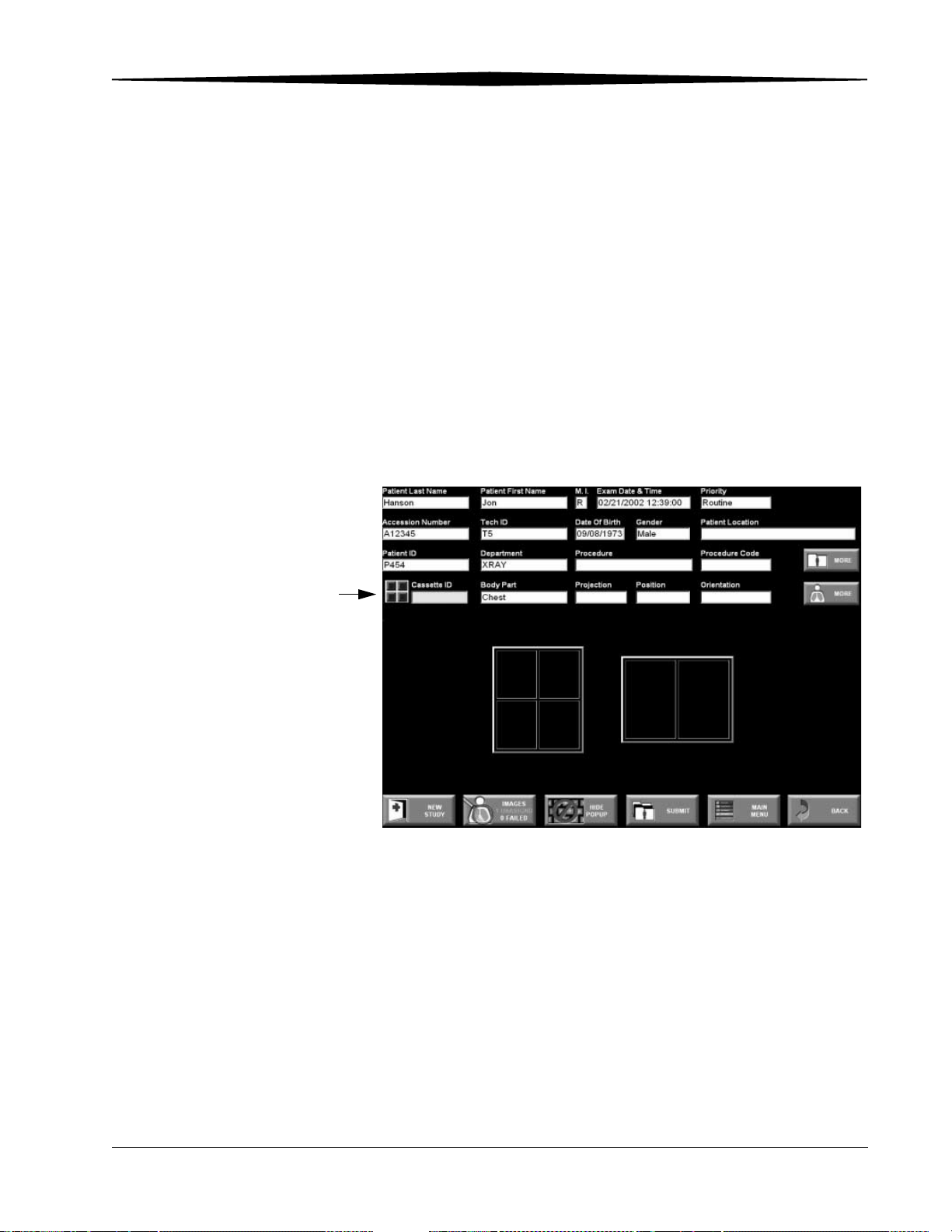
Scanning, Viewing and Printing Images
Printing Multi-format Images
Multi-format
Button
Multi-format images are only delivered to print destinations. With
Multi-format printing:
• All Multi-format layouts must contain at least two images.
• Images from cassettes can be placed together in a multi-format print.
• Images are printed in portrait mode for four-up and landscape mode for
two-up multi-format prints.
• Image aspect ratio is maintained.
• Images are printed with saved Image Processing parameters.
• Images may be included from any cassette size.
• The destination printer must support minification.
When two or more images exist, and a print destination is configured on the
system, the Multi-format button displays next to the cassette ID.
June 3, 2003 1F3742 5-21
Page 70

Scanning, Viewing and Printing Images
1. Touch Multi-format.
2. Touch a layout.
The available images for the study appear, along with the cassette sizes.
NOTE: Depending on the printer type and film size, printing multi-format
images may not be possible.
Colored borders around the thumbnails indicate the image’s
multi-format status.
5-22 1F3742 June 3, 2003
Page 71

Scanning, Viewing and Printing Images
•Green — include the image in a multi-format layout, and it has not
been included in a previous multi-format layout.
•Gray—the image was used in a previous multi-format layout. You can
still add the image to the new layout.
•Yell ow—the image was placed in the current multi-format layout.
The two-up or four-up print layout appears at the bottom of the screen.
The yellow border indicates where the next image will be placed in the
format.
3. Touch the image you want to add to the layout. The image is added to the
print layout and the yellow border moves to the next multi-format layout
location. A yellow border is added to the image at the top of the screen to
indicate it has been added to the layout.
• To remove the image from the multi-format layout location, touch the
trash can and then touch the image.
• To select a different layout location, touch the location, then touch the
image you want to place there.
4. Continue selecting images until the layout is complete.
NOTE: You don’t have to add an image to every multi-format layout location
for four-up images. Blank locations will print D-max.
You cannot flip or rotate images from the Multi-format screen. If the
image is saved in the wrong orientation, it rotates to fit in the layout.
To change the image orientation, go to the Image Viewer screen and
make the changes.
Because four-up images always print in portrait mode and two-up
images always print in landscape mode, you can only change the
image orientation by 180 degrees.
5. Touch Accept Image to print the multi-format image. It is sent to the
displayed printer unless you change the destination using Select
Destination.
If you cannot print the multi-format layout to the selected destination, an
error message appears. Select a new printer destination that will support the
format, re-select the images and place them in the layout, and print.
See “Appendix C: Printing Exceptions“.
June 3, 2003 1F3742 5-23
Page 72

Scanning, Viewing and Printing Images
The following table lists common Kodak printers and the CR cassette sizes
(images) that can be printed in two-up or four-up format. See “Appendix C:
Printing Exceptions“.
Kodak Printer Film Size Cassette Size
Supported on
Two-Up Format
Kodak DryView 8100 Laser
Imager
35 x 43 35 x 43
35 x 35
24 x 30
18 x 24
Kodak DryView 8200 Laser
Imaging System
35 x 43 35 x 43
35 x 35
24 x 30
18 x 24
35 x 35 35 x 43
35 x 35
24 x 30
18 x 24
11 x 14 35 x 43
Cassette Size
Supported on
Four-Up Format
35 x 43
35 x 35
24 x 30
18 x 24
35 x 43
35 x 35
24 x 30
18 x 24
35 x 43
35 x 35
24 x 30
18 x 24
35 x 43
Comment
9410 or MIM C
*Minify must be
selected in MIMDUI,
Contact the Technical
Service Center if this
does not work.
MIM B+ or MIM C
MIM B+ or MIM C
MIM B+ or MIM C
Kodak DryView 8500 Laser
Imaging System
Kodak DryView 8700 Laser
Imaging System
35 x 35
24 x 30
18 x 24
11 x 14 35 x 43
35 x 35
24 x 30
18 x 24
35 x 43 35 x 43
35 x 35
24 x 30
18 x 24
35 x 35
24 x 30
18 x 24
35 x 43
35 x 35
24 x 30
18 x 24
35 x 43
35 x 35
24 x 30
18 x 24
Two-up works with
9410 or MIM C
Four-up works with
MIM C ONLY
See “Appendix C:
Printing Exceptions“.
5-24 1F3742 June 3, 2003
Page 73

Scanning, Viewing and Printing Images
Kodak Printer Film Size Cassette Size
Supported on
Two-Up Format
Kodak Ektascan 2180 Laser
Printer
35 x 43 35 x 43
35 x 35
24 x 30
18 x 24
35 x 35 35 x 43
35 x 35
24 x 30
18 x 24
11 x 14 35 x 43
35 x 35
24 x 30
18 x 24
10 x 12 none none
8 x 10 35 x 43
Cassette Size
Supported on
Four-Up Format
35 x 43
35 x 35
24 x 30
18 x 24
35 x 43
35 x 35
24 x 30
18 x 24
35 x 43
35 x 35
24 x 30
18 x 24
35 x 43
Comment
MIM B + or MIM C
Two-up works with
MIM B+ or MIM C
Four-up works with
MIM C only
Two-up works with
MIM B+ or MIM C
Four-up works with
MIM C only
MIM C only
35 x 35
24 x 30
18 x 24
35 x 35
24 x 30
18 x 24
Other Multi-format Settings
Multi-format Only Check Box
Image Review Screen During the delivery cycle of a multi-format print, an entry is made in the
You can compose multi-format prints of images of a variety of statuses:
Available, Delivered, Failed, etc. To change the status of an image printed in a
multi-format print from Available to Delivered, touch the Multi-format Only
check box.
IMPORTANT: Do not check the Multi-Format Only check box if you plan
on delivering the image to an archive or workstation. You
may forget to deliver them.
Image Review list. Each multi-format print has a separate entry containing the
pertinent patient information and an icon representing the type of format
being printed.
June 3, 2003 1F3742 5-25
Page 74

Scanning, Viewing and Printing Images
Deleting Multi-format Images
Printing Text
The multi-format image (not the individual image) is removed when the
image has been delivered successfully.
To re-deliver an image that failed, touch the Multi-Format image icon to
display the Image Destination Status Screen. You can then re-deliver the
image.
To remove an image from multi-format, touch the trash can icon and then
touch the image.
There are two text printing options: Internal and External Text Box. The
available options depend on how the Key Operator has configured your
System.
See see “Text Box Configuration (Option)” on page 9-45.
Select the type you want and the location at the Image Processing screen.
5-26 1F3742 June 3, 2003
Page 75

Scanning, Viewing and Printing Images
Printing Internal Text Boxes
The text box content is configured by your Key Operator.
1. At the Image Viewer screen, touch Image Processing.
Text Box
2. Touch the Internal Text Box check box.
3. You can print the text box in eight different locations, that is, horizontally
or vertically in each corner. Touch the edge of the corner you want the
text box to appear.
4. Print the image.
June 3, 2003 1F3742 5-27
Page 76

Scanning, Viewing and Printing Images
Printing External
Text Boxes
External
Text box
indicator
The External Text Box content is configured by your Key Operator.
1. At the Image Viewer screen, touch Image Processing.
2. Touch the External check box.
3. Touch the arrow under the check box to select Portrait or Landscape
orientation.
4. Print the image.
5-28 1F3742 June 3, 2003
Page 77

True-size Printing (Option)
CAUTION:
To support True-size printing, a printer must support DICOM
Requested Image Size. See the printer’s DICOM Conformance
Statement to determine if a printer supports Requested Image
Size.
True-size Printing produces the same size image you would get if you were
using a film screen system. To achieve True-size on most printers, data is
cropped from the edge of the image.
WARNING:
True-size Printing delivers the latent image to the
destination at 100%, +/-2%. Because variations exist in
scanners and printers, use caution when using these images
for exact measurements. Kodak recommends that you use a
known marker at the subject level when making the
exposure and calculating image magnification.
Scanning, Viewing and Printing Images
The size of the crop box is determined by the selected destinations.
Printers cannot print to the edges of the film. Therefore, to be able to print
True-size printing, the image is cropped (outside edge data is discarded)
before the film is printed.
1. At the Image Viewer screen, touch Image Processing.
2. Touch the True-size Print check box.
June 3, 2003 1F3742 5-29
Page 78
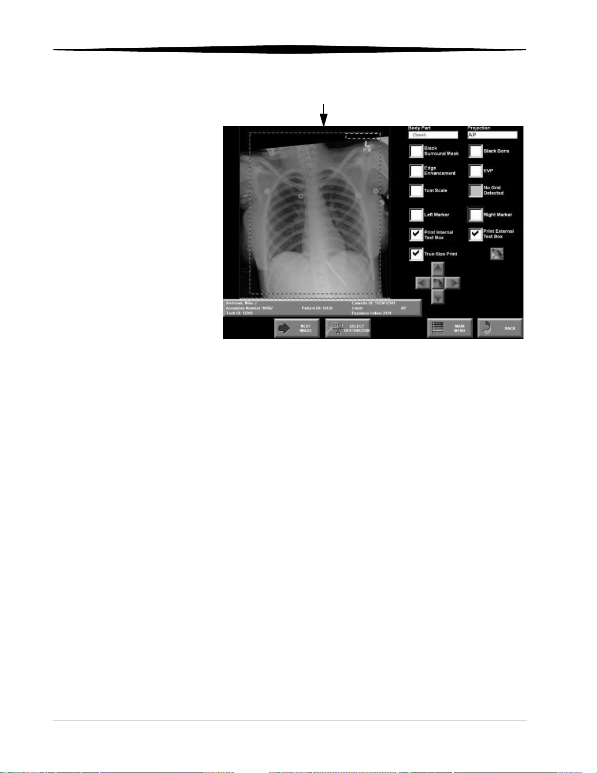
Scanning, Viewing and Printing Images
Crop Box
3. Use the arrows to move or rotate the crop box.
4. Print the image.
5-30 1F3742 June 3, 2003
Page 79

Scanning, Viewing and Printing Images
1 cm Tick Marks Use the 1 cm Tick Marks option to “burn” markers into the image to help you
evaluate image size. The system optionally prints markers 1 cm apart along 2
adjacent sides of either 1-up or multi-format images. The marks are placed so
that the distance between any two consecutive marks is 1 cm when the image
is printed True-size. For images that are not printed True-size, you can use the
spacing of the tick marks to determine the amount of image minification. For
example, the distance between tick marks would be 0.9 cm for an image that
is printed at 90% of True-size.
June 3, 2003 1F3742 5-31
Page 80

Scanning, Viewing and Printing Images
5-32 1F3742 June 3, 2003
Page 81

6
Maintaining Image Quality
Guidelines for Optimizing Image Quality
Understanding the cause-and-effect relationship of the parameters applied
during image processing helps you optimize image quality. To produce an
optimum image from the CR System, the proper collimation, positioning,
technique, and the optimum combination of processing parameters are
required.
Performing the Exam The Image Processing Library (IPL) is an object-oriented library of image
processing algorithms incorporated into the CR System. Each body part and
projection combination produces a unique look for a given image.
When using Storage Phosphor plates, the following suggestions will help you
obtain optimum image quality:
• Apply as much collimation as is practically possible on all images.
• Capture only one view per cassette (such as a Posterior Anterior (PA)
hand on one cassette and a Lateral hand on a separate cassette).
• If you must capture more than one view on a cassette, for best quality
group like views together (such as PA hand and Oblique hand). In this
situation, Kodak recommends that you:
– Minimize the collimation between separate views (such as a thin line
of collimation shown between two views).
– Minimize the exposure overlap between the separate views.
– Use the same bone thickness in each image.
Image Processing The CR System produces the highest-quality images when:
• The exam, body part, and projection information is accurate and
complete.
• You enter exam information for a cassette rather than default body part
and projection information.
• You make contrast and brightness adjustments only if necessary, before
sending the image across the network.
NOTE: The Image Processing parameters and default settings are
pre-configured. If changes need to be made, contact your Key
Operator.
June 3, 2003 1F3742 6-1
Page 82
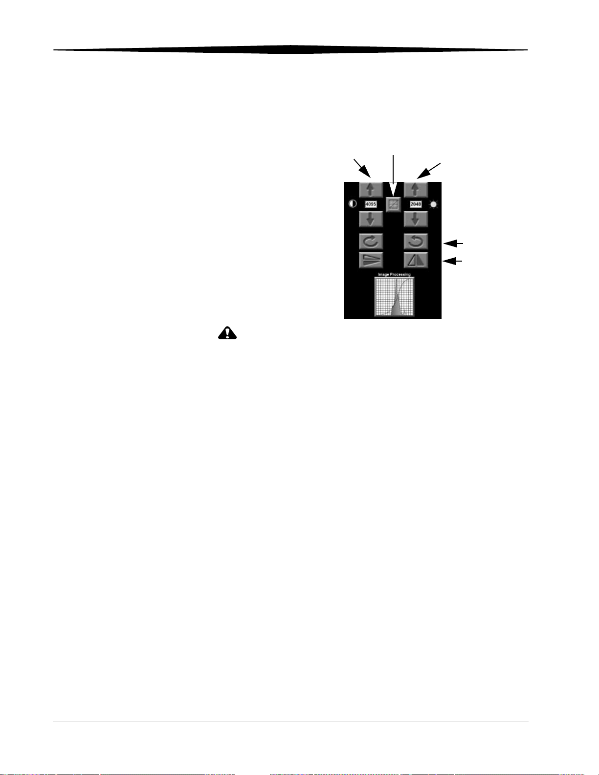
Maintaining Image Quality
Changing Image Orientation
Adjusting Contrast and Brightness
Touch the appropriate button to rotate or flip an image. You can rotate
through 360° by rotating in steps of 90°.
Contrast
CAUTION:
Do not change the contrast and brightness unless absolutely
necessary.
Tonescale
Brightness
Rotate
Flip
Changing Window Widths (Contrast)
Changing Window Levels (Brightness)
An image’s contrast and brightness are determined by the window width
(contrast) and window level (brightness). When you adjust the settings the
image display changes.
The default values are:
– Contrast: 4095
– Brightness: 2048
Adjust the straight line portion of the curve to include as much histogram data
as possible. The numerical values are the number of input code values. See
“Changing Image Tonescale” on page 6-3.
Increasing the window width reduces the contrast.
NOTE: TIP - to return to the default Contrast and Brightness settings (4095
and 2048) touch the Tonescale button two times.
Increasing the window level increases the brightness. Changing the window
level affects the overall appearance, but does not affect contrast.
6-2 1F3742 June 3, 2003
Page 83
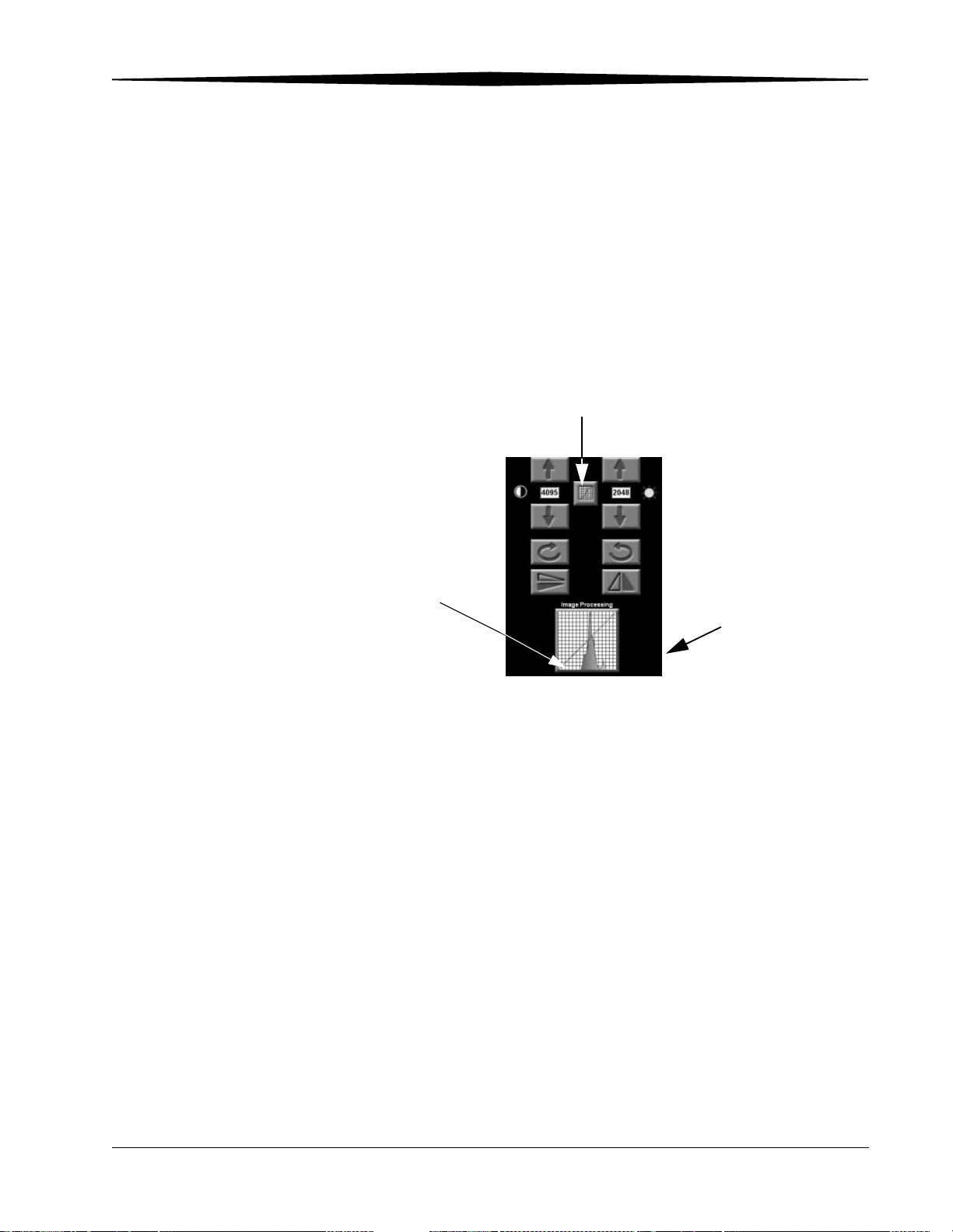
Maintaining Image Quality
Changing Image Tonescale
If a processed image is not acceptable, you may be able to salvage the image
by using the raw data.
1. Touch Image Tonescale to view the raw data.
2. Adjust the Brightness and Contrast to generate an acceptable image.
NOTE: Touch Image Tonescale again if you want to return to the Processed
Data.
For optimum results, try to get as much of the tonescale line in the image
data area as possible.
Image Tonescale
Look Up Table (LUT) Data
Tonescale Line
Histogram
Raw Data
June 3, 2003 1F3742 6-3
Page 84
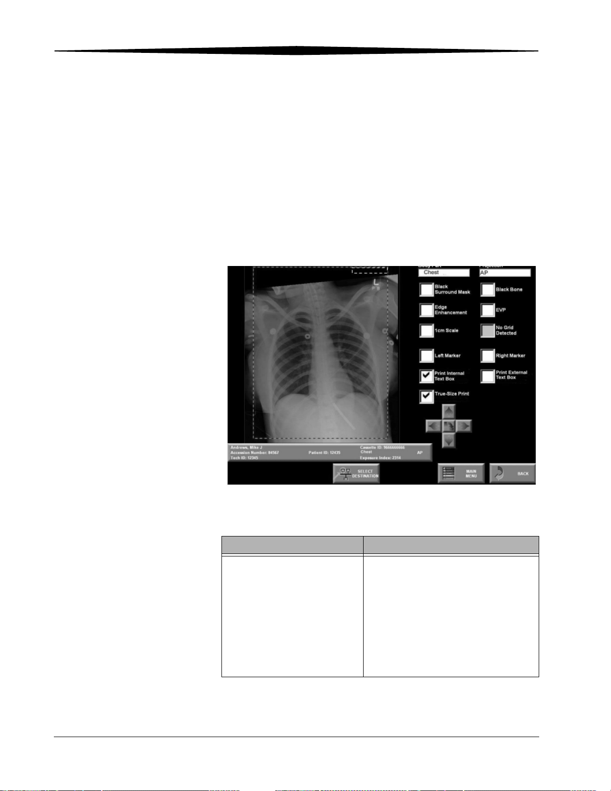
Maintaining Image Quality
Image Processing
You can alter or reprocess an image at the Image Processing screen. The
Image Reprocessing parameters are set up and stored in memory by the
Application Consultant or a Key Operator who has attended an advanced
Image Processing class. If these changes do not produce satisfactory results,
contact your Application Consultant. Software features which have not been
purchased will be grayed out and therefore not selectable.
To reprocess an image:
1. At the Image Viewer screen, touch the Image Processing histogram
at the bottom of the screen.
Image Processing
Use the following table to make your image processing selections.
Parameter Procedure
Black Surround Mask, Black
Bone, Edge Enhancement, EVP,
1 cm Scale, and Grid
Suppression
1. Touch the appropriate check box to
select a function. If you cannot select
it, the option is not available.
2. Touch Reprocess Image.
3. Evaluate the image. If the parameter
does not improve the image, touch
the check box again and then
reprocess.
6-4 1F3742 June 3, 2003
Page 85
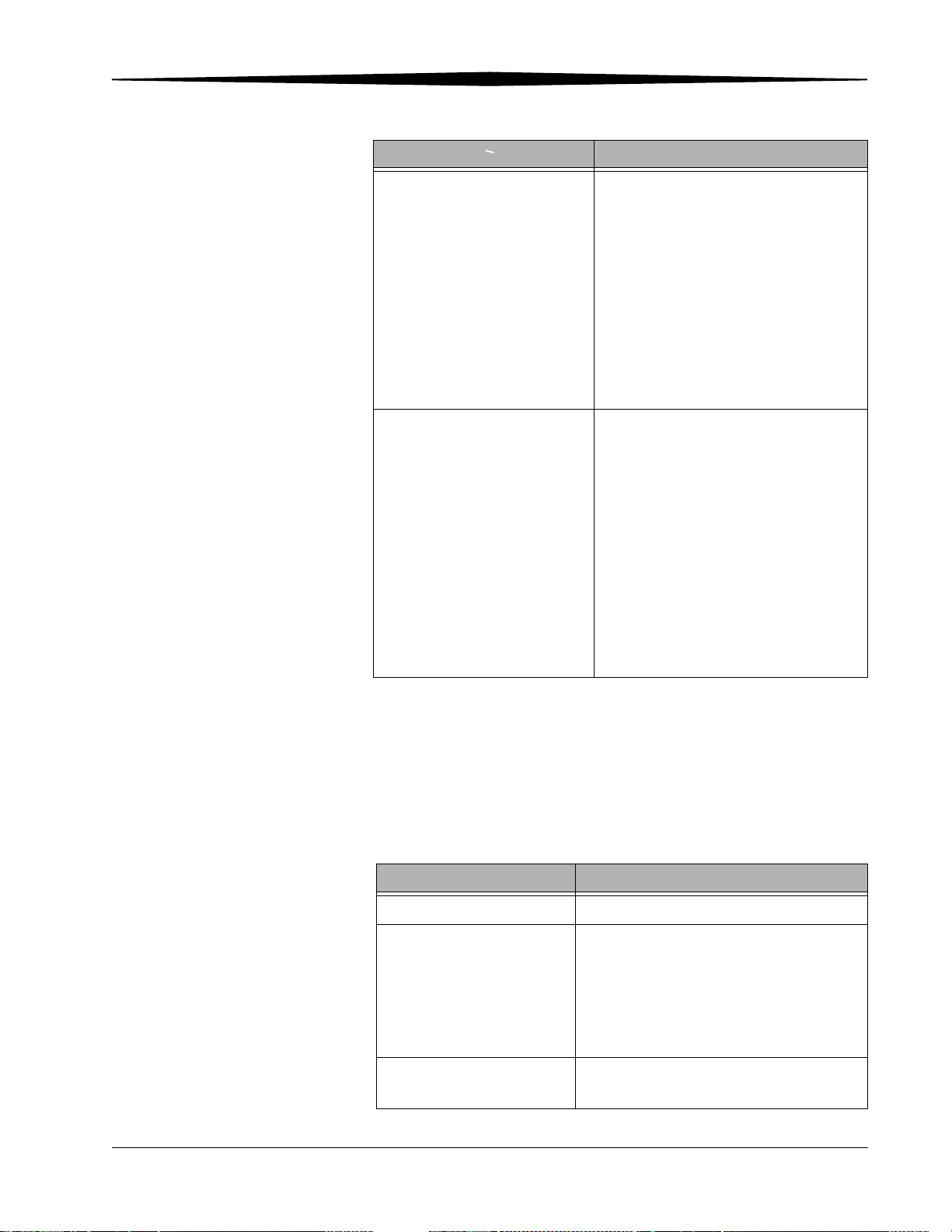
Maintaining Image Quality
Parameter Procedure
Left Marker or Right Marker
Print Internal Text Box
Print External Text Box
True-Size Print
1. Touch the Left Marker or Right
Marker check box.
2. Touch the image where you want to
locate the marker.
The marker appears on the image.
3. To remove the marker, touch the
check box.
NOTE: This function is set by the Key
Operator. See “CR Display
Configuration” on page 9-36.
Touch any corner to place the text box.
The text box can be orientated either
horizontally or vertically. Touch the edge
of the corner you wish the text box to
align with. For more information see
page 5-27.
To print the External Text Box, touch the
check box. For more information see
page 5-28.
To select True-size Printing, select the
check box. For more information see
page 5-29.
NOTE: You cannot reprocess an image if the image has been accepted and
delivered across the network. You must create a copy of the image,
modify the copy, and send it to the proper destinations.
• Touch Redeliver Image to redeliver the image without making changes.
• Touch Create a Copy of this Image to display a copy of the image you
can modify.
Function Description
Black Surround Mask Blackens the area around the image.
Edge Enhancement Accentuates edges in the image. The default
edge enhancement values should seldom
need to be changed. Changing Edge
Enhancement should only be done by
someone with a clear understanding and
good working knowledge of digital imaging.
1 cm Scale Adds a 1 cm scale perpendicular to the
borders of the image.
June 3, 2003 1F3742 6-5
Page 86

Maintaining Image Quality
Function Description
Left or Right Marker Adds left (L) or right (R) markers to an
image to identify the left and right side of the
image.
Black Bone Reverses the light and dark areas of the
image to provide an optional view of the
image details.
EVP Increases the latitude of the image while
preserving the contrast of the image details.
Grid Suppression Detects and suppresses grid lines.
Eliminates moire patterns or line pattern
seen when an image is viewed on a monitor
or a workstation.
Print Internal Text Box
Print External Text Box
True-size Printing
See page 5-27 and page 5-28 for printing
text boxes; see page 9-51 for information on
configuring text boxes.
For information on True-size Printing see
page 5-29.
6-6 1F3742 June 3, 2003
Page 87

Improving Image Characteristics
Use the following table to look up a general quality problem and find possible
solutions.
Two tools are available for you to improve an image-quality problem:
• Change contrast and brightness
• Change user parameters (a Key Operator function)
NOTE: If you cannot correct the problem, in the United States and Canada
contact Kodak Customer Service Center (CSC) for service at
1-800-328-2910, prompt 2, then prompt 3 for further assistance. For
other locations, contact your Kodak service center or representative.
Image Problem Recommendations
Maintaining Image Quality
Image is too light
Image is too dark
Image is too flat
Image contrast is too high
Image is too noisy (no edge
enhancement chosen or applied)
Image is too grainy (with edge
enhancement applied)
• Decrease the brightness, and then adjust the contrast if needed. If this
causes clipping in the region of interest, switch to the raw image and
adjust brightness and contrast on the raw image.
• If the images are consistently too light, contact your Key Operator.
• Increase the brightness, and then adjust the contrast if needed. See
“Adjusting Contrast and Brightness” on page 6-2. If this causes clipping in
the region of interest, switch to the raw image and adjust brightness and
contrast on the raw image.
• If the images are consistently too dark, contact your Key Operator.
• Increase the contrast, and adjust the brightness.
• If images are consistently too flat, contact your Key Operator.
• Decrease the contrast and brightness.
• If image contrast is consistently too high, contact your Key Operator.
• The image may require more exposure to reduce the amount of noise.
Check the exposure index in the exam information.
• The image may require more exposure to reduce the amount of noise.
Check the exposure index in the exam information.
• Cancel the edge enhancement selection.
• Change the tonescale to Raw Data tonescale type. See “Changing Image
Tonescale” on page 6-3. See also “Adjusting Contrast and Brightness” on
page 6-2. Remove edge enhancement by changing it to None.
• Turn off EVP.
• If the enhanced images are consistently too grainy, speak to your Key
Operator.
Image is all white or all black
June 3, 2003 1F3742 6-7
• Confirm an image was captured on the plate.
• Remove black surround.
Page 88
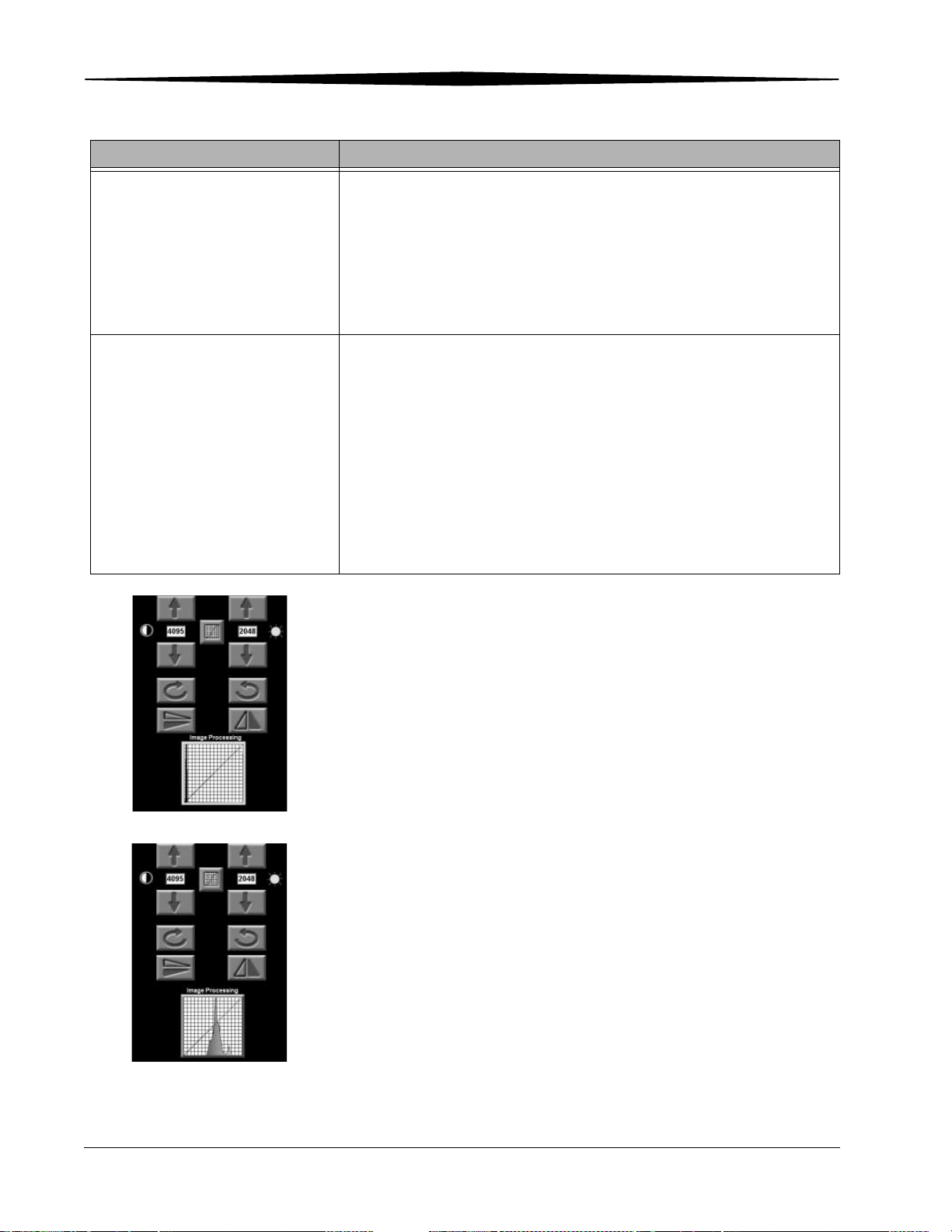
Maintaining Image Quality
Image Problem Recommendations
Printed image has stripes
through it
No Image
• Check laser printer for errors; find out if problem is restricted to one or
for all prints produced on that particular printer.
• Check clinical and diagnostic workstations to see if the same problem
occurs when viewing the distributed image.
• Print SMPTE from the AC screen. If stripes exist on the test, it may be a
printer issue. If stripes do not exist, there is an issue on the CR System or
the monitor. Contact the Applications Consultant.
• Confirm that an image was captured on the phosphor screen. This can be
done by either of the following methods:
1. Changing the tonescale to Raw Data and turning off Edge
Enhancement, Black Surround Mask, EVP, and Grid Suppression. If
there is no visible image, there was nothing captured on the
phosphor screen.
2. Viewing the histogram. If the histogram is outside of the LUT curve on
both the processed and raw data, there was no image captured.
• If the image was captured, adjust the contrast and brightness to produce
an acceptable image.
Data Histogram No. 1
This histogram’s position on the LUT shows that no image was captured.
Raw Data Histogram No. 2
This histogram’s position on the LUT shows that an image was captured.
If image processing fails, the Histogram displays a linear LUT (straight
line) and the displayed image has very low contrast. Adjust the
brightness and contrast to generate an acceptable image.
6-8 1F3742 June 3, 2003
Page 89

Maintaining Image Quality
Processed Data Histogram
This histogram’s position on the LUT shows that an image was captured and
processed.
NOTE: The Exposure Index is the average code of the pixels in the activity
histogram used for processing the image. The image data is the data
within the boundary box used for processing the image for the body
part. Use the Exposure Index to monitor whether your exposure
factors are in the correct range.
June 3, 2003 1F3742 6-9
Page 90

Maintaining Image Quality
6-10 1F3742 June 3, 2003
Page 91

7
Troubleshooting
Error Messages
Error Messages appear following an error in operation. Follow the
instructions on the screen to return to normal operation. If that doesn't
correct the problem, contact the Key Operator for your department. If the
Error Message repeats, call the Kodak Technical Support Center at
1-800-328-2910, prompt 2, then prompt 3. For other locations, contact your
Kodak service center or Kodak representative.
Releasing Cassette Jams
1. At the Main Menu touch Utility Menu.
2. Touch System Recovery.
3. Touch Release Cassette.
4. Touch Clear Cassette Jam to clear the jam in the system.
5. Touch Release Cassette to move the cassette to the home position.
System Reset
6. Remove the cassette.
If the problem persists, call the Kodak Technical Support Center at
1-800-328-2910, prompt 2, then prompt 3. For other locations, contact your
Kodak service center or Kodak representative.
NOTE: Before calling Kodak, locate the CR System K Number. You must
provide the K Number when calling in a problem.
If the CR System stops responding to your touch commands, you might solve
the problem by turning off the system and turning it back on.
1. Open the front door and press the CR Computer Power button. The
computer attempts a controlled shutdown. Wait one minute, if the screen
hasn’t changed, go to step 2.
2. Press and hold the UPS OFF button until you hear a beep. The unit turns
off.
To restart, see page 3-1.
June 3, 2003 1F3742 7-1
Page 92

Troubleshooting
System Status
The System Status screen provides information on disk and memory
utilization, database statistics. and erase lamps.
1. At the Main Menu touch Utility Menu.
2. Touch System Status.
Clear Pending Images
There may be times when you want to clear images that do not successfully go
to a destination. Clear Pending Images reboots the machine and sets all
images to failed. After the reboot, communications to the destinations is
restarted.
1. At the Main Menu touch Utility Menu.
2. Touch System Recovery.
3. Touch Clear Pending Images.
4. Touch Clear Pending Images again.
Slow System Response
WARNING:
System memory usage increases over time. This can lead to
significantly slower response time, image delivery
problems, or a virtual memory error at the CR System or the
ROP. If this occurs, reboot the CR System. At very high
volumes, such as 300 images per day, it may be necessary to
reboot the system weekly.
If you are experiencing slow system response, check your physical memory.
See “System Status” on page 7-2.
If the physical memory utilization is high, reboot the CR System.
1. At the Main Menu touch Utility Menu.
2. Touch System Shutdown.
3. Touch Reboot.
NOTE: If the system has ROPs connected to it, reboot the ROPs after the CR
System is rebooted.
Incorrect Image Grouping
If you are unfamiliar with CR System operation and implementing DICOM
standards, incorrect image grouping on workstations and archives may
occur.
7-2 1F3742 June 3, 2003
Page 93

Troubleshooting
If you change an accession number, patient identification number, and patient
name assigned to all images in a study, it changes for all images in the study,
including images that have been sent by the system. This causes image
grouping problems on workstations and archives if an image is redelivered
with altered information.
If one study image has been routed, the CR System displays a warning message
when you attempt to change the patient identification number or accession
number. The system displays the warning “Changing the data may cause
incorrect grouping of images at a Workstation or an Archive.” No warning
appears if you attempt to modify the patient name.
Modifying Patient Information
Improperly entering patient information for a new patient record, or study,
may result in image grouping problems at workstations and archives.
To create a new patient record, select a patient record from the Patient
Worklist screen, or touch one of the following functions:
• New Patient
• New Study
These functions generate a unique ID for each study.
NOTE: Do not delete and enter information for more than one patient on the
Patient Information screen.
June 3, 2003 1F3742 7-3
Page 94

Troubleshooting
7-4 1F3742 June 3, 2003
Page 95

8
Maintaining Equipment and Cassettes
Cleaning the CR System Surfaces
Clean the outer surfaces of the CR System only with water using a soft, lint-free
cloth. Dampen the cloth, then wipe the outer surfaces lightly.
CAUTION:
Do not use alcohol or alcohol-based products to clean the
pinch rollers, belts, entrance guide or any urethane parts on
the CR System.
Cleaning the ROP Touch Screen
Clean the screen regularly to ensure its proper operation:
CAUTION:
To avoid damage do not use liquid cleaners, abrasive cleaners
or strong solvents, such as benzine, to clean the touch screen.
Also, do not spray aerosol cleaners directly on the touch
screen.
1. Turn off the touch screen.
2. Spray glass cleaner on a soft cloth, then gently wipe the touch screen
viewing surface.
3. Use a soft cloth dampened with water to clean the housing around the
touch screen.
June 3, 2003 1F3742 8-1
Page 96
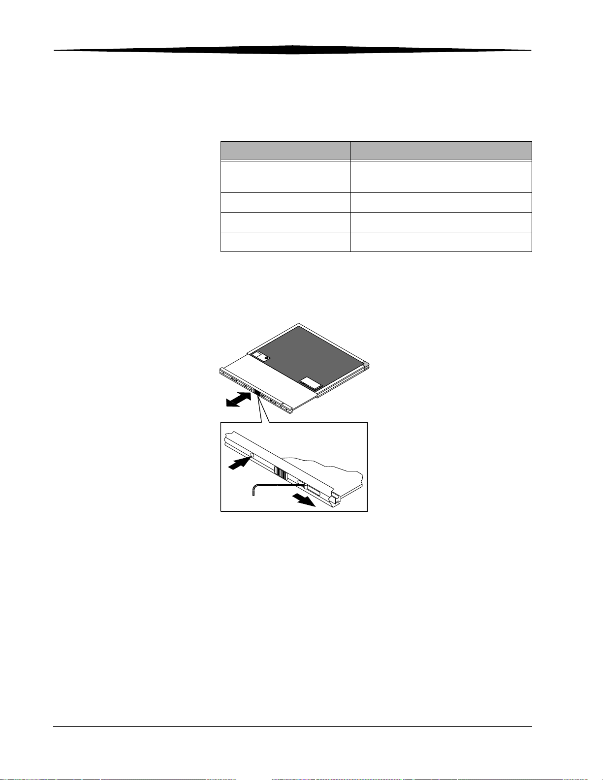
Maintaining Equipment and Cassettes
Cleaning Storage Phosphor Screens
Special Cleaning Materials
Catalog Number Description
1064930 Kodak Intensifying Screen Cleaner and
Antistatic Solution
N/A Soft, lint-free cloth
N/A Isopropyl Alcohol
N/A Bleach
Removing the Phosphor Screen
1. Move the latch to the right to release the plate and phosphor screen.
2. Remove the plate and phosphor screen from the cassette shell.
e
id
S
e
b
u
T
Tube Side
H187_2442GC
Removing the Phosphor Screen
8-2 1F3742 June 3, 2003
Page 97

Maintaining Equipment and Cassettes
Cleaning the Phosphor Screen
Clean storage phosphor screens every 500 exposures, every 30 days, or when
artifacts appear. Under normal use conditions, storage phosphor screens will
eventually show wear. This may occur from abrasion of the protective
overcoat or inadvertent physical damage to the surface. Certain chemical
agents, such as non-approved screen cleaners, hand lotions, topical
medications, food, etc., may also damage the screens. Screen wear can result
in artifacts on radiographs. Storage phosphor screens and cassettes used for
medical diagnosis should be inspected periodically and replaced when wear
is evident.
Phosphor screens are extremely sensitive to moisture. Exposure to moisture
can cause damage to the phosphor screens, which results in image-quality
problems.
The phosphor screen is coated with a moisture-resistant polymer blend. The
overcoat is very thin (less than 0.001 inch) and has limited resistance to
mechanical abrasion that may occur during cleaning. It is possible to damage
the protective coating during use or cleaning. This can permanently damage
the screen.
IMPORTANT: Read and follow instructions in the Material Safety Data
Sheets (MSDS) for KODAK Intensifying Screen Cleaner and
Antistatic Solution and KODAK MIN-R Screen Cleaner prior
to use.
CAUTION:
Be careful not to damage the phosphor screen or any of the
screen edges.
1. Remove the screen and attached plate from the cassette shell. See
“Removing the Phosphor Screen” on page 8-2.
2. Clean the phosphor screen with a soft, dry, lint-free cloth. Most of the
minus density artifacts are caused by loose dirt. Normally, a gentle wipe
is all that is needed.
3. If the dry cloth does not remove the dirt, clean screens with
Kodak Intensifying Screen Cleaner and Antistatic Solution or with Kodak
MIN-R Screen Cleaner as follows:
CAUTION:
Never apply solution directly to the surface of the screen.
Excessive moisture may damage the screen.
CAUTION:
For all cleaning methods, do not soak the cloth.
a. Lightly dampen a small, soft, lint-free cloth with solution.
b. Wipe the soiled area with the damp cloth. After cleaning, wipe the
screen with a soft, dry, lint-free cloth.
June 3, 2003 1F3742 8-3
Page 98

Maintaining Equipment and Cassettes
NOTE: You may remove stubborn soil with Isopropyl Alcohol, following
CAUTION:
For all cleaning methods, avoid pressure and excessive
rubbing, which may damage the screen surface.
steps 1 through 3. After cleaning with Isopropyl Alcohol, re-treat the
screen with screen cleaner. Do not use soaps or detergents
containing brightening agents.
WARNING:
Isopropyl Alcohol is a flammable solvent. It can cause eye
irritation and dry skin. Wash hands with soap and water
following maintenance procedures. Read and follow
instructions in Material Safety Data Sheet (MSDS) prior to
use.
CAUTION:
Isopropyl Alcohol may contain peroxides that can permanently
damage the phosphor screen. If you cannot verify the purity of
your Isopropyl Alcohol, Kodak recommends that you use only
KODAK Intensifying Screen Cleaner and Antistatic Solution, or
KODAK MIN-R Screen Cleaner to clean your phosphor screen.
If a bleach solution is necessary to clean the phosphor screen:
1. Lightly dampen a soft cloth with bleach diluted 1:10 with water.
2. Carefully clean only the soiled area on the phosphor screen.
3. Rinse the phosphor screen with a soft cloth moistened with
Kodak Intensifying Screen Cleaner and Antistatic Solution.
4. After the soil is removed, dry the phosphor screen gently with a soft,
dry, lint-free cloth.
Some other screen-cleaning agents may leave residues, which will seriously
affect the emission of these screens. The use of any cleaning agents other than
those specifically suggested for cleaning KODAK Storage Phosphor Screens is
not recommended.
Replacing the Phosphor Screen
After cleaning the phosphor screen:
1. Insert the phosphor screen into the cassette.
2. Insert a tool into the hole to snap the cassette closed.
8-4 1F3742 June 3, 2003
Page 99

Cassette Cautions
Maintaining Equipment and Cassettes
CAUTION:
You cannot ship cassettes contaminated with blood or other
body fluids to an Eastman Kodak Company facility for
evaluation unless they have been decontaminated. Please
utilize “universal precautions” and decontaminate the
cassettes with either an EPA registered tuberculocidal (list B)
or dilute bleach (1:10 with water) solution prior to shipping.
CAUTION:
Kodak DirectView CR Cassettes contain lead. Disposal of
components that contain lead may be regulated due to
environmental conditions. For disposal or recycling
information, contact your local authorities or visit the
Electronics Industry Alliance web site at http://www.eiae.org.
June 3, 2003 1F3742 8-5
Page 100

Maintaining Equipment and Cassettes
Cleaning Cassettes
IMPORTANT: Remove the storage phosphor screen from the cassette shell
Clean the surface of the cassette shell with any of the following solutions.
Other solutions are not recommended.
• Kodak Intensifying Screen Cleaner and Antistatic Solution
• Mild soap-and-water solution
• Isopropyl Alcohol
NOTE: Be sure the cassette shell is completely dry before replacing the
before cleaning the cassette exterior.
phosphor screen. You may need to use compressed air to blow
debris from the cassette interior.
8-6 1F3742 June 3, 2003
 Loading...