

Page 1
Confidential
Restricted
Information
{InstallationInstructs}{Production}{Health Group}{ExternalAndInternal}
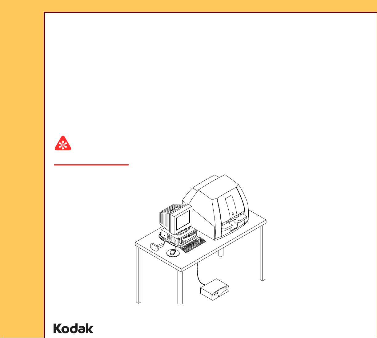
INSTALLATION INSTRUCTIONS
for the
Kodak DirectView CR 500 SYSTEM
Service Code: 4366
Important
Qualified service personnel must install this equipment.
Publication No. II4366-1
15DEC06
Supersedes II4366-1
23NOV04
H195_0016BC
© EASTMAN KODAK COMPANY, 2006 HEALTH GROUP
Page 2

INSTALLATION INSTRUCTIONS
15DEC06
II4366-1
Page
2 of 91
PLEASE NOTE The information contained herein is based on the experience and knowledge relating to the
subject matter gained by Eastman Kodak Company prior to publication.
No patent license is granted by this information.
Eastman Kodak Company reserves the right to change this information without notice, and
makes no warranty, express or implied, with respect to this information. Kodak shall not be
liable for any loss or damage, including consequential or special damages, resulting from an y
use of this information, even if loss or damage is caused by Kodak’s negligence or other fault.
This equipment includes parts and assemblies sensitive to damage from electrostatic
discharge. Use caution to prevent damage during all service procedures.
Table of Contents
Description Page
Safety . . . . . . . . . . . . . . . . . . . . . . . . . . . . . . . . . . . . . . . . . . . . . . . . . . . . . . . . . . . . . . . . 4
Installation . . . . . . . . . . . . . . . . . . . . . . . . . . . . . . . . . . . . . . . . . . . . . . . . . . . . . . . . . . . . 7
Connecting the UNINTERRUPTED POWER SUPPLY (UPS). . . . . . . . . . . . 7
Removing the Packing Material . . . . . . . . . . . . . . . . . . . . . . . . . . . . . . . . . . . 8
Setting the Optional ISOLATION TRANSFORMER . . . . . . . . . . . . . . . . . . . 9
Connecting the Equipment . . . . . . . . . . . . . . . . . . . . . . . . . . . . . . . . . . . . . . 11
Installing the Optional MODEM . . . . . . . . . . . . . . . . . . . . . . . . . . . . . . . . . . . 19
Installing the DVD/CD WRITER . . . . . . . . . . . . . . . . . . . . . . . . . . . . . . . . . . . 20
Connecting the Power . . . . . . . . . . . . . . . . . . . . . . . . . . . . . . . . . . . . . . . . . . 23
Setting the Configurations Options . . . . . . . . . . . . . . . . . . . . . . . . . . . . . . . 24
Doing the Setup. . . . . . . . . . . . . . . . . . . . . . . . . . . . . . . . . . . . . . . . . . . . . . . . 25
Checking the MIMDUI Configuration of the LOCALHOST . . . . . . . . . 25
Adding the CD/DVD DESTINATION to the MIM . . . . . . . . . . . . . . . . . . 27
Setting the Configuration of the DVD DRIVE. . . . . . . . . . . . . . . . . . . . 32
Instructing the Customer in Using CD/DVDs. . . . . . . . . . . . . . . . . . . . 33
Setting the Network User Interface. . . . . . . . . . . . . . . . . . . . . . . . . . . . 34
Setting the “Regional IP Parameters” . . . . . . . . . . . . . . . . . . . . . . . . . 36
Setting the “Global Parameters” . . . . . . . . . . . . . . . . . . . . . . . . . . . . . . 37
Setting the MONITOR . . . . . . . . . . . . . . . . . . . . . . . . . . . . . . . . . . . . . . . 43
Enabling Full Resolution Image Viewing . . . . . . . . . . . . . . . . . . . . . . . 44
Installing and Setting the Optional Features . . . . . . . . . . . . . . . . . . . . 44
Setting the HIS/RIS Parameters . . . . . . . . . . . . . . . . . . . . . . . . . . . . . . . 46
Adding a PRINTING DEVICE . . . . . . . . . . . . . . . . . . . . . . . . . . . . . . . . . 50
Adding a STORAGE DEVICE . . . . . . . . . . . . . . . . . . . . . . . . . . . . . . . . . 65
Enabling the BAR CODE READER . . . . . . . . . . . . . . . . . . . . . . . . . . . 72
Page 3

INSTALLATION INSTRUCTIONS
15DEC06
II4366-1
Page
3 of 91
Storing the Setup Data. . . . . . . . . . . . . . . . . . . . . . . . . . . . . . . . . . . . . . 75
Installing the Kodak DirectView REMOTE OPERATIONS PANEL (ROP) 76
Setting the Configurations for the ROPs. . . . . . . . . . . . . . . . . . . . . . . 76
Setting the Configuration for the ROP to More than One CR SYSTEM 78
Installing the Kodak REMOTE PATIENT DATA ENTRY STATION. . . 79
Setting the Configuration for the Remote Key Operator . . . . . . . . . . 81
Setting the Configuration for the RPDES. . . . . . . . . . . . . . . . . . . . . . . 82
Operating the RPDES . . . . . . . . . . . . . . . . . . . . . . . . . . . . . . . . . . . . . . . 83
Making a SHORTCUT for the RPDES . . . . . . . . . . . . . . . . . . . . . . . . . . 84
Setting the “User Name” and “Password” . . . . . . . . . . . . . . . . . . . . . 85
Checking the Operation . . . . . . . . . . . . . . . . . . . . . . . . . . . . . . . . . . . . . . . . . 87
Page 4
15DEC06
II4366-1
Page
4 of 91
INSTALLATION INSTRUCTIONS Safety
Section 1: Safety
This information defines the safety and information icons used in this publication.
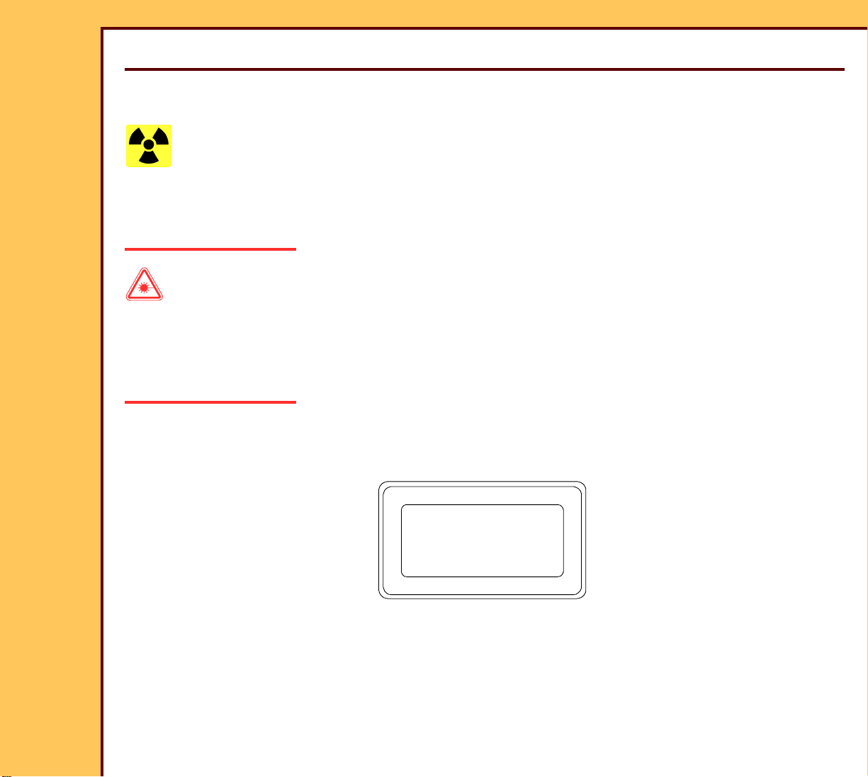
Radiation
This icon is used for conditions that could cause personal injury from radiation.
Use of controls, adjustments or performance of procedures other than those specified herein
can result in hazardous radiation exposure.
Laser Warning
This icon is used for conditions when a laser beam could cause injury to a person.
This equipment uses a visible red LASER. Prevent direct exposure to the beam from the
LASER. Radiation from the LASER can be accessed when the equipment is operated with
the TOP, SIDE, BACK PANELS, and the inner LIGHT LOCK COVER removed.
CAUTION
CAUTION
CAUTION
Class 3B laser radiation
Class 3B laser radiation
Class 3B laser radiation
when open. Avoid exposure
when open. Avoid exposure
when open. Avoid exposure
to beam.
to beam.
to beam.
H195_0004AC
H195_0004AC
H195_0004AC
This equipment is a Class I Laser equipment. This equipment complies with DHHS regulation
21 CFR Chapter I Subchapter J and IEC 60825-1.
Page 5
15DEC06
II4366-1
Page
5 of 91
INSTALLATION INSTRUCTIONS Safety
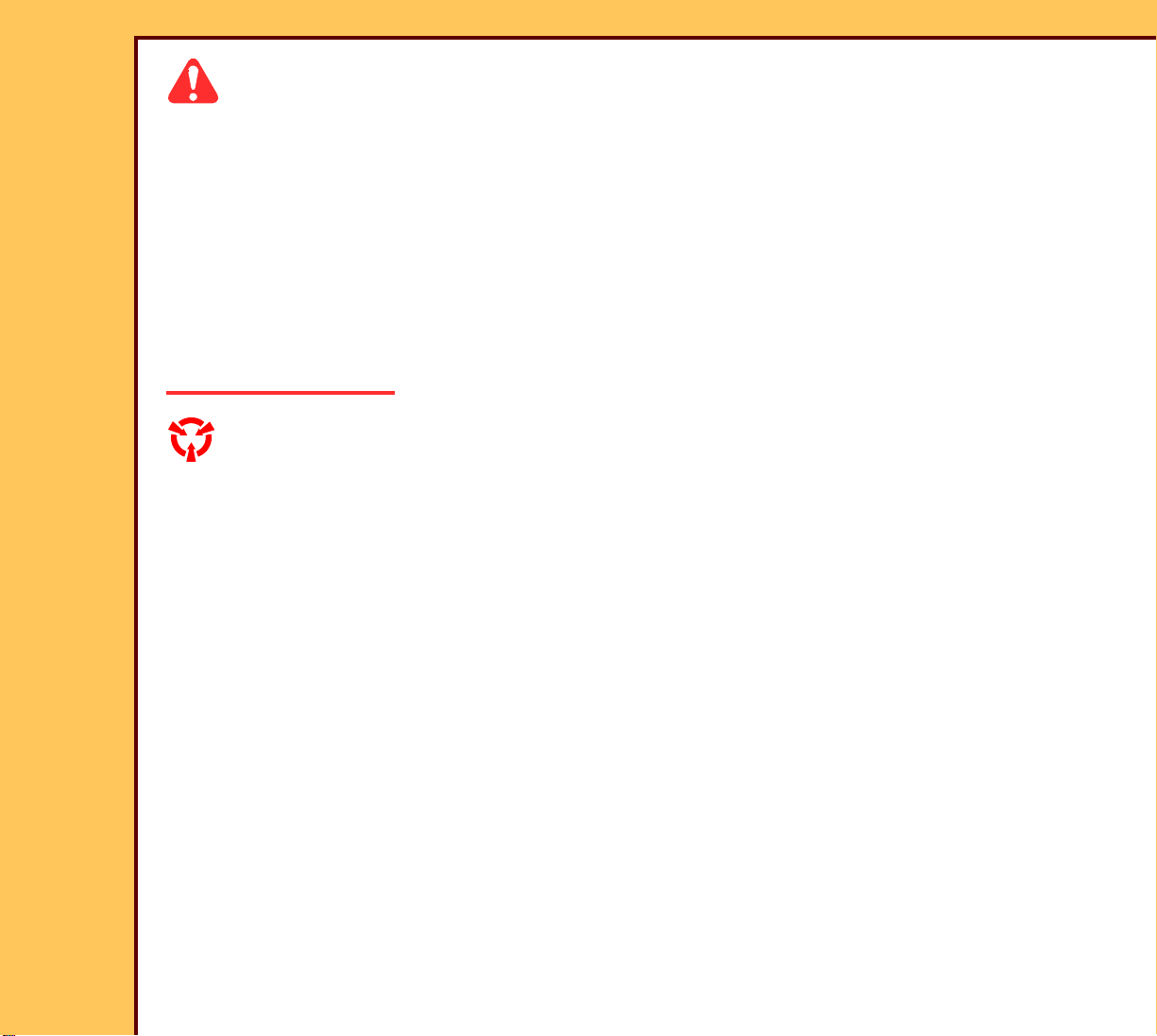
Caution
This icon is used for conditions that could cause injury to a person, or damage to the
equipment or software data.
The READER is 90 kg (200 lb). Use more than one person to lift and place on the TABLE.
The ERASE LAMPS have a small quantity of mercury. If an ERASE LAMP breaks, special
clean-up is necessary because of health and environmental concerns. Ventilate the area.
Clean up the area using a mercury VACUUM CLEANER, or other device, to prevent dust and
vapor. Store the waste in closed containers.
Used ERASE LAMPS must be discarded in accordance with federal, state and local
regulations.
ESD
Possible damage from electrostatic discharge.
This icon is used for conditions that could cause damage to the equipment.
Electrostatic discharge (ESD) is a primary source of:
• equipment failure
• equipment repairs
A person cannot detect an electrostatic charge of less than 3,500 V, but 30 V can cause
damage to components in the equipment.
Page 6
INSTALLATION INSTRUCTIONS Safety
15DEC06
II4366-1
Page
6 of 91
Preventive Measures
• Check for an ESD WARNING LABEL before doing any procedure involving ESD-sensitive
components. All sensitive components have graphic LABELS which include instructions.
Use all label instructions.
• Wear a GROUNDING STRAP when you touch ESD-sensitive components. Check that the
CLIP remains fastened to a ground that has a clean surface with no paint.
• Repair components in an ESD-protection area or use a PORTABLE GROUNDING MAT.
• When moving ESD-sensitive components from area to area, insert and transpor t the
components in the special material made for the transport of these components.
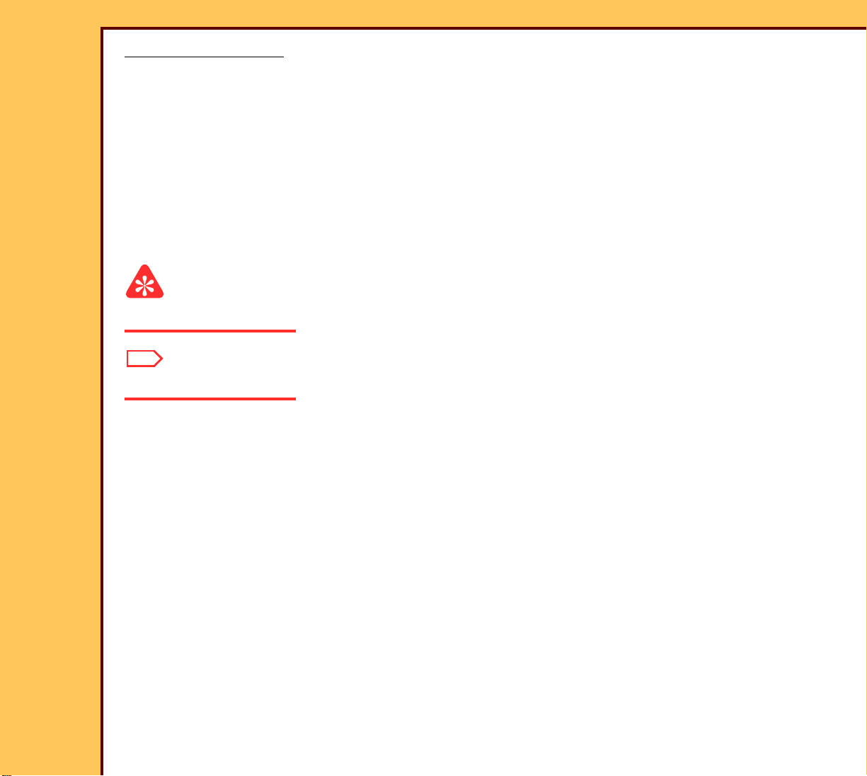
Important
This icon is used for important information.
Note
This icon is used for additional information.
Page 7
15DEC06
II4366-1
Page
7 of 91
INSTALLATION INSTRUCTIONS Installation
Section 2: Installation
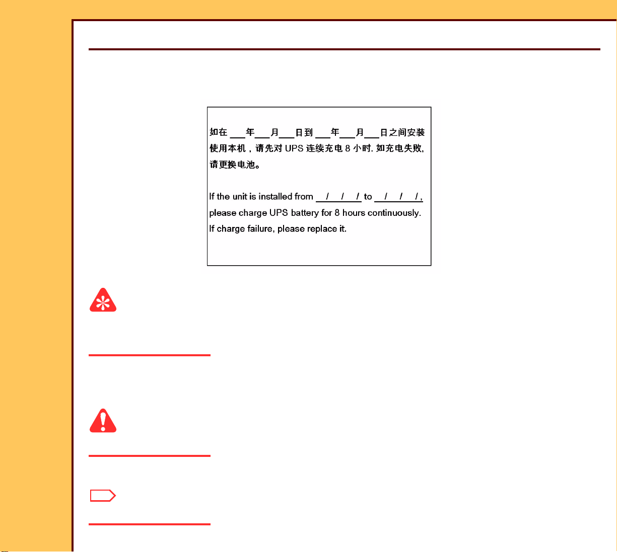
Connecting the UNINTERRUPTED POWER SUPPLY (UPS)
Figure 1 UPS LABEL
Important
• The UPS is in the accessor y carton with the UPS LABEL.
• You must start to charge the UPS before unpacking the CR 500 SYSTEM.
1 Locate the accessory carton with the UPS.
2 Unpack the UPS.
Caution
Dangerous Voltage
3 Connect the UPS to the main power at the site.
Note
The UPS starts to charge.
Page 8
INSTALLATION INSTRUCTIONS Installation
15DEC06
II4366-1
Page
8 of 91
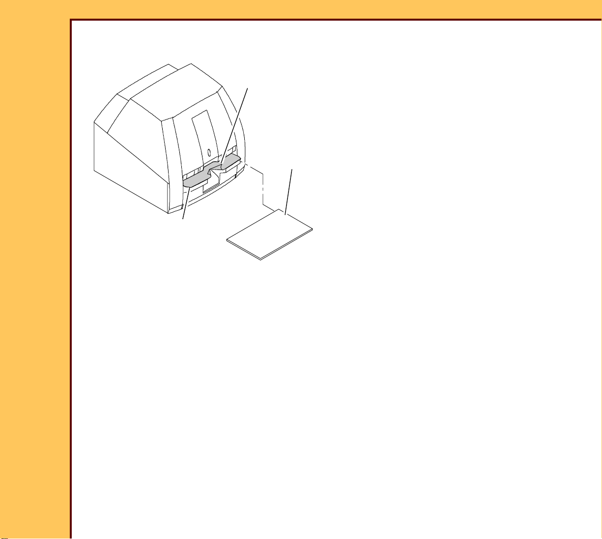
Removing the Packing Material
PROTECTIVE
FILM COVER
SHIPPING
HOLDER
CASSETTE INTERFACE
PLATEN
H195_1120ACA
H195_1120AC
1 Remove the SHIPPING HOLDER.
2 Cut the PROTECTIVE FILM COVER
and remove from the CASSETTE
INTERFACE PLATEN.
Page 9
INSTALLATION INSTRUCTIONS Installation
INPUT
240V
100V
110V
120V
200V
220V
POWER OFF
115 V Switch
SET ONLY WITH
OUTPUT
230 V Switch
200V
220V
240V
120V
110V
100V
230
H195_0088BC
H195_0088BCA
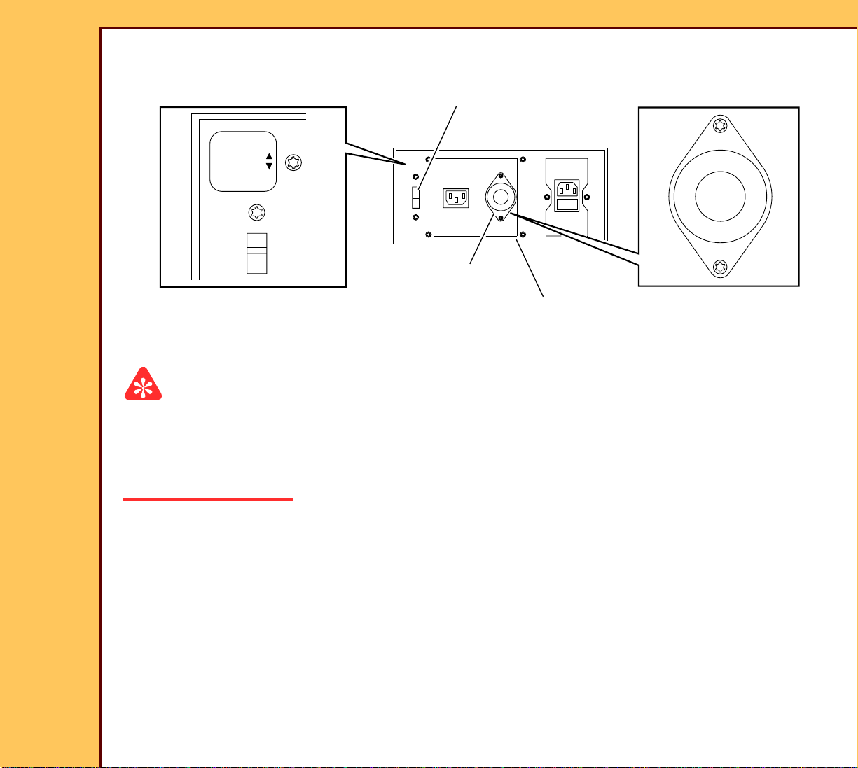
INPUT SWITCH
OUTPUT SWITCH
optional ISOLATION
TRANSFORMER
15DEC06
II4366-1
Page
9 of 91
Setting the Optional ISOLATION TRANSFORMER
Important
• You must set the 2 SWITCHES to the correct voltage for your region.
• You must install the ISOLATION TRANSFORMER for “Medical Electrical Equipment”
installations, IEC 60601-1-1. See SPECIFICATIONS for the Kodak DirectView CR 500
SYSTEM, 1F5928.
1 If necessary, use the following tables to set the INPUT and OUTPUT SWITCHES on the
optional ISOLATION TRANSFORMER to the correct input and output voltage for your
region.
Page 10
15DEC06
II4366-1
Page
10 of 91
INSTALLATION INSTRUCTIONS Installation
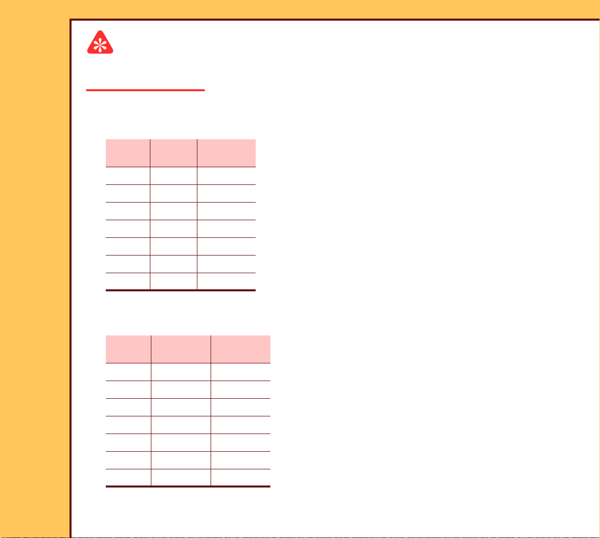
Important
For systems using the optional ISOLATION TRANSFORMER with the Belkin
UNINTERRUPTIBLE POWER SUPPLY (UPS), you must use the Belkin 230 V UPS.
Table 1 Setting the SWITCHES for the optional ISOLATION TRANSFORMER with the
Belkin 230 V UPS
Line
Voltage
INPUT
SWITCH
OUTPUT
SWITCH
110 110 230
115 110 230
120 120 230
127 120 230
220 220 230
230 220 230
240 240 230
Table 2 Setting the SWITCHES for the optional ISOLATION TRANSFORMER with the
Desk Power 120 or 230 V UPS
Line
Voltage
INPUT
SWITCH
OUTPUT
SWITCH
110 110 115
115 110 115
120 120 115
127 120 115
220 220 230
230 220 230
240 240 230
Page 11
INSTALLATION INSTRUCTIONS Installation
15DEC06
II4366-1
Page
11 of 91
Table 3 Setting the SWITCHES for the ISOLATION TRANSFORMER with the
Delta UPS - Japan only
Line
Voltage
INPUT
SWITCH
OUTPUT
SWITCH
100 100 115
200 200 115
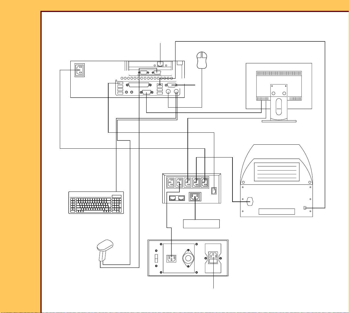
Connecting the Equipment
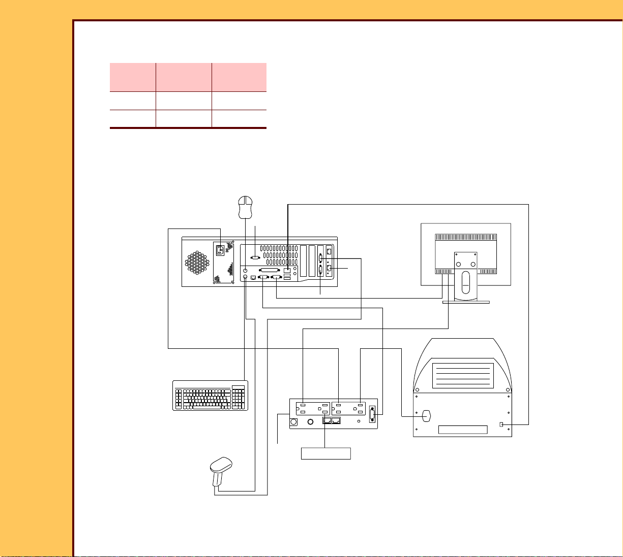
Figure 2 CR 500 SYSTEM - with Belkin 120 V UPS
A
COMPUTER
MOUSE
B
C
E
D
MONITOR
F
K
G
H195_0035DC
KEYBOARD
optional BAR
CODE READER
H
L
UPS
O
P
M
I
MODEM
J
READER
Page 12
INSTALLATION INSTRUCTIONS Installation
15DEC06
II4366-1
Page
12 of 91
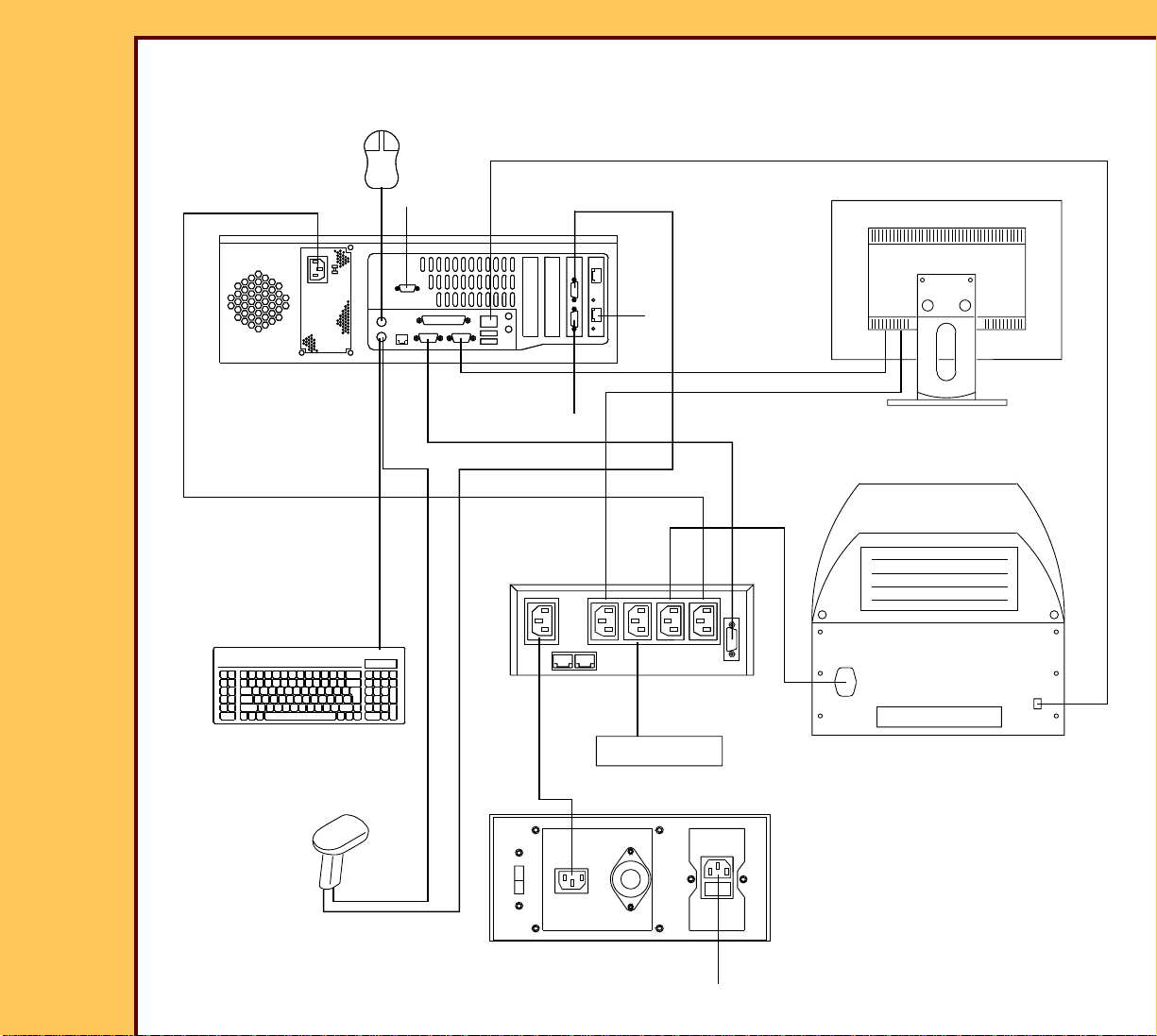
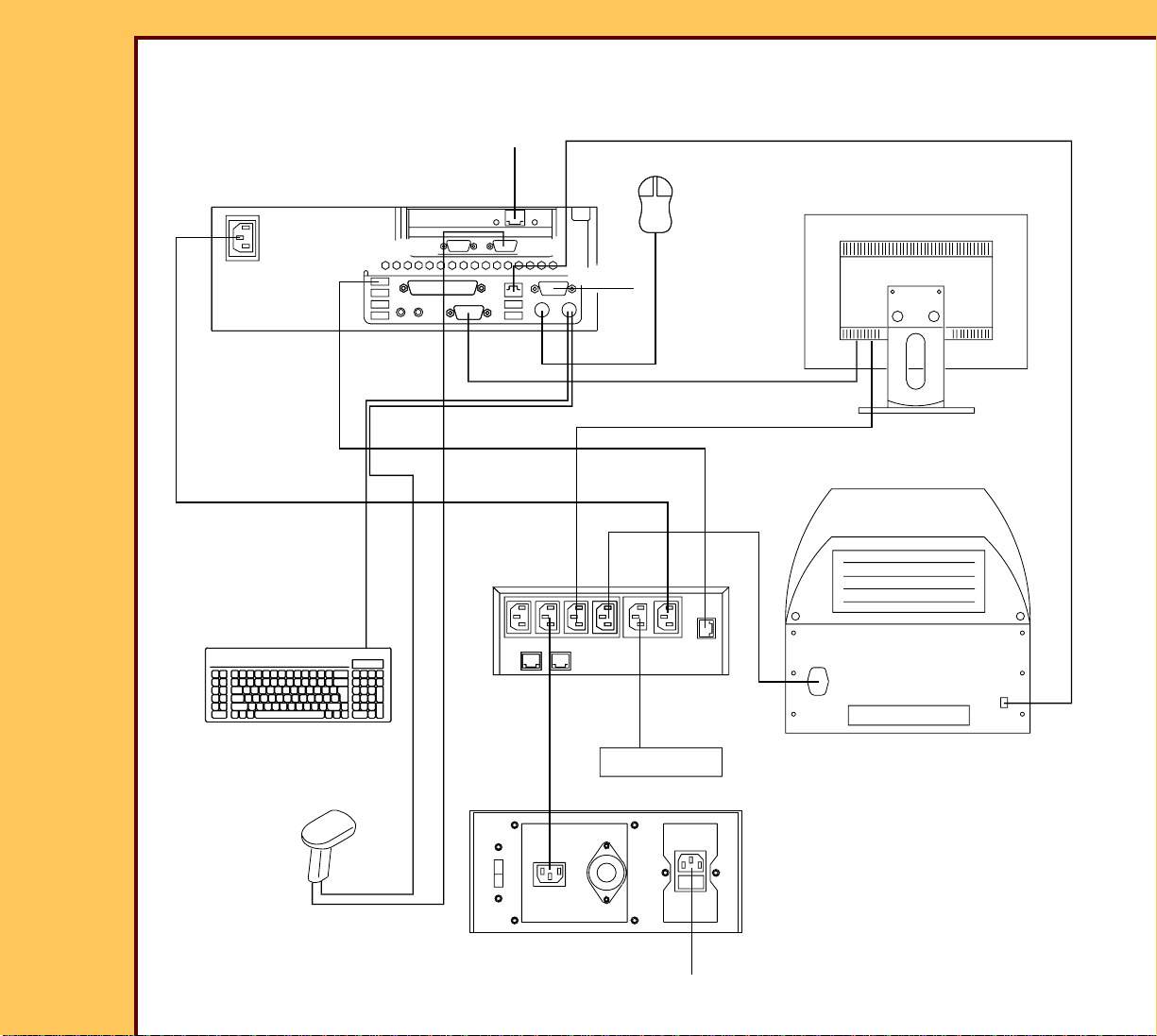
Figure 3 CR 500 SYSTEM - with the Belkin 230 V UPS
MOUSE
D
A
B
C
F
F
COMPUTER
E
K
UPS
L
PO
KEYBOARD
KEYBOARD
MONITOR
G
H
READER
J
optional BAR
CODE READER
M
I
MODEM
100V
240V
110V
220V
120V
200V
optional ISOLATION
TRANSFORMER
N
H195_0037DC
Page 13
INSTALLATION INSTRUCTIONS Installation
15DEC06
II4366-1
Page
13 of 91
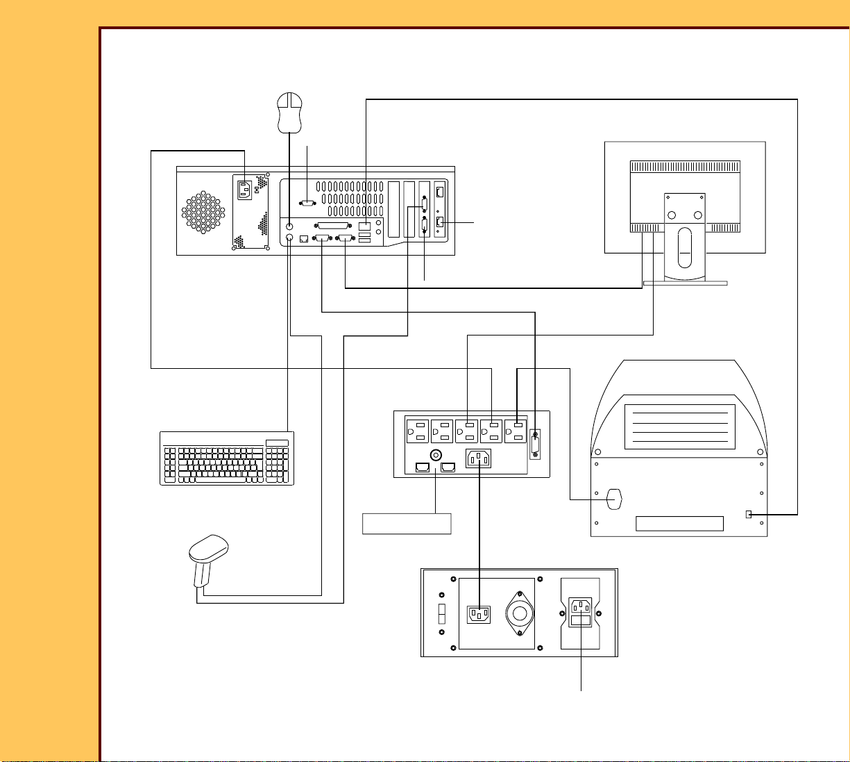
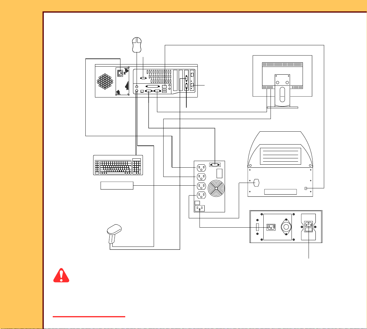
Figure 4 CR 500 SYSTEM - with the Desk Power 120 V UPS - RS-232 Connection
MOUSE
D
MONITOR
A
B
C
F
COMPUTER
K
G
E
H
L
UPS
J
READER
KEYBOARD
optional BAR
CODE READER
H195_0089DC
PO
MODEM
I
M
1
0
0
V
0
4
2
220V
V
V
0
20
optional ISOLATION
TRANSFORMER
V
110V
1
2
0
N
Page 14
INSTALLATION INSTRUCTIONS Installation
15DEC06
II4366-1
Page
14 of 91
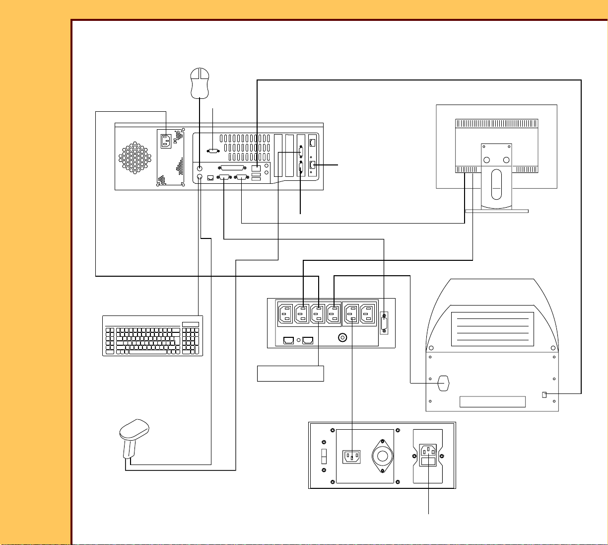
Figure 5 CR 500 SYSTEM - with the Desk Power 230 V UPS - RS-232 Connection
MOUSE
D
A
B
C
MONITOR
F
COMPUTER
E
K
G
H
READER
L
UPS
J
KEYBOARD
optional BAR
CODE READER
H195_0090DC
PO
MODEM
I
M
100V
240V
110V
220V
120V
200V
optional ISOLATION
TRANSFORMER
N
Page 15
INSTALLATION INSTRUCTIONS Installation
15DEC06
II4366-1
Page
15 of 91
Figure 6 CR 500 SYSTEM - IBM Model 8212 Computer - with the Desk Power 120 V UPS -
USB Connection
D
A
COMPUTER
KEYBOARD
KEYBOARD
F
com1
com3
E
UPS
L
OP
MOUSE
MONITOR
B
com4
K
G
H
READER
J
optional BAR
CODE READER
M
I
MODEM
1
0
0
V
V
0
4
2
110V
220V
1
2
0
V
V
0
0
2
optional ISOLATION
TRANSFORMER
N
H195_0095DC
Page 16
INSTALLATION INSTRUCTIONS Installation
15DEC06
II4366-1
Page
16 of 91
Figure 7 CR 500 SYSTEM - IBM Model 8212 Computer - with the Desk Power 230 V UPS -
USB Connection
D
F
COMPUTER
A
com1
com3
E
UPS
L
PO
KEYBOARD
KEYBOARD
MOUSE
MONITOR
B
com4
K
G
H
READER
J
optional BAR
CODE READER
M
I
MODEM
1
0
0
V
V
0
4
2
110V
220V
1
2
0
V
V
0
0
2
optional ISOLATION
TRANSFORMER
N
H195_0096DC
Page 17
INSTALLATION INSTRUCTIONS Installation
15DEC06
II4366-1
Page
17 of 91
Figure 8 CR 500 SYSTEM - Japan only with the Delta UPS
MOUSE
D
A
COMPUTER
KEYBOARD
KEYBOARD
B
C
F
F
E
K
G
H
L
I
MONITOR
READER
MODEM
J
PO
optional BAR
CODE READER
H195_0091DC
M
TRANSFORMER
100V
240V
110V
220V
120V
00V
2
ISOLATION
N
Caution
• On computers with 2 COM PORTS on the MOTHER BOARD, C OM 1 is next to the
MONITOR CONNECTOR.
• Dangerous Voltage
Page 18

INSTALLATION INSTRUCTIONS Installation
15DEC06
II4366-1
Page
18 of 91
1 Connect:
Item CABLE From: To: Notes
A POWER COMPUTER UPS
B MOUSE MOUSE COMPUTER
C MODEM - optional MODEM COMPUTER COM 2 • 2.4 GHz only
• Only used on
PCs with a RS232 UPS
D INTERNAL
COMPUTER READER
NETWORK
EUPS
COMMUNICATION
FHOSPITAL
COM 1 UPS Use only the top
USB Port.
network COMPUTER
NETWORK
G MONITOR MONITOR MONITOR
CONNECTOR
H MONITOR POWER MONITOR UPS
I MODEM POWER -
MODEM UPS
optional
J SYSTEM POWER CR 500 SYSTEM UPS
K MODEM - optional MODEM COMPUTER COM 4 3.0 GHz only
L KEYBOARD KEYBOARD KEYBOARD
CONNECTOR
M POWER UPS • power source
• ISOLATION
Do not connect at
this time.
TRANSFORMER
N POWER ISOLATION
TRANSFORMER
power source Do not connect at
this time.
Page 19
15DEC06
II4366-1
Page
19 of 91
INSTALLATION INSTRUCTIONS Installation
Item CABLE From: To: Notes
O BARCODE READER -
optional
BARCODE
READER
COMPUTER COM 3
P BARCODE READER -
optional
BARCODE
READER
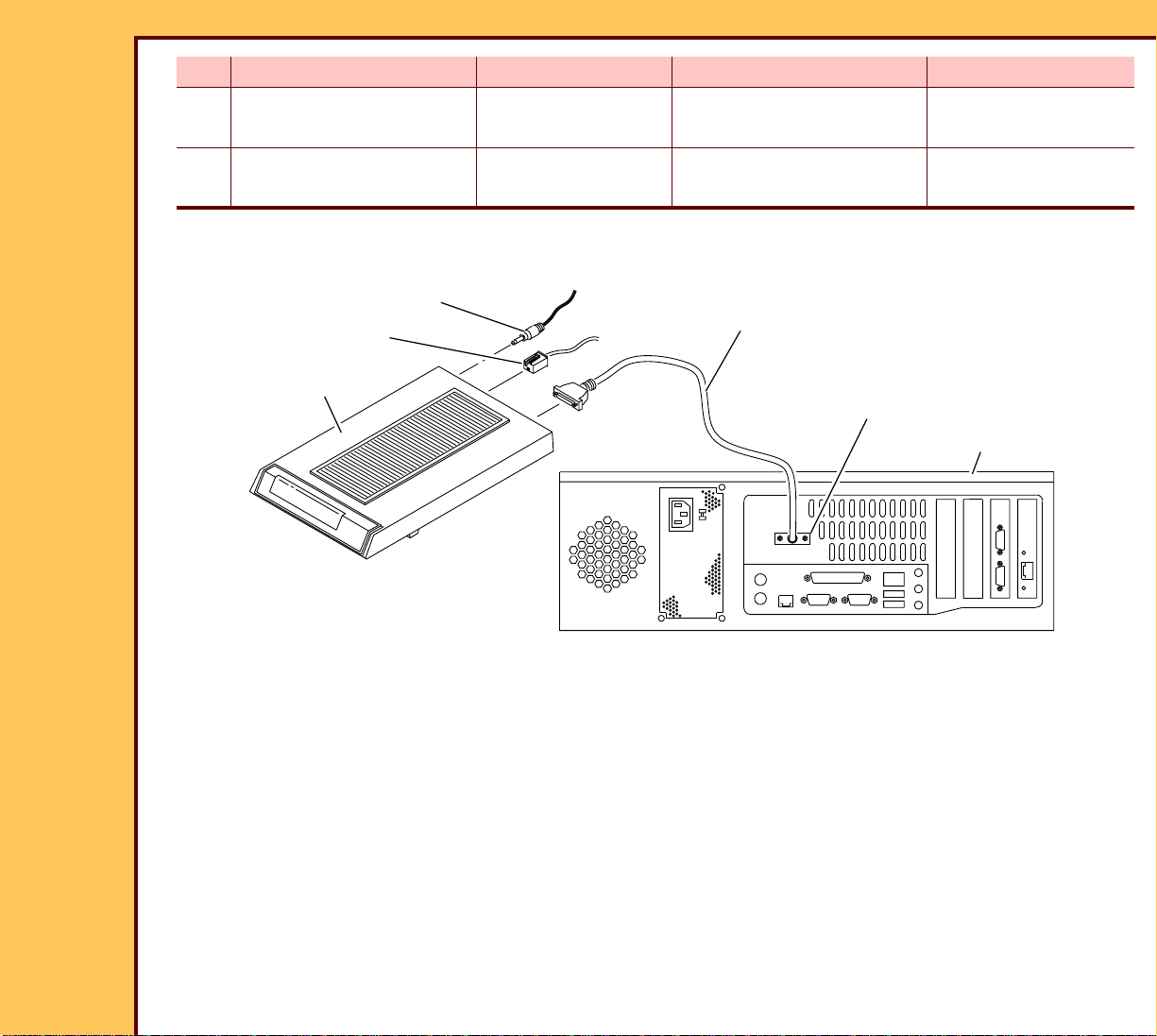
Installing the Optional MODEM
POWER ADAPTER
telephone line
MODEM
H195_0032BCA
H195_0032BC
1 Remove the MODEM from the cart on.
2 Connect:
KEYBOARD
CONNECTOR
RS-232 CABLE
COM 2
COMPUTER
• POWER ADAPTER to the back of the MODEM
• telephone line to the MODEM
• RS-232 CABLE to:
– MODEM
– COM 2 for 2.4 GHz computer only
– Com 4 for 3.0 GHz computer only
Page 20
15DEC06
II4366-1
Page
20 of 91
INSTALLATION INSTRUCTIONS Installation
Caution
Dangerous Voltage
3 Connect the POWER ADAPTER to the power source.
4 Energize the MODEM.
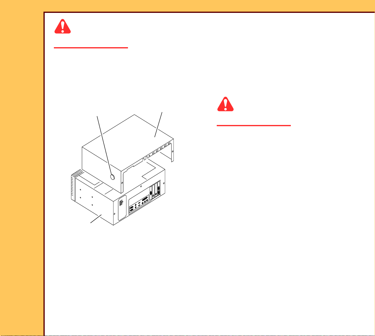
Installing the DVD/CD WRITER
2 BUTTONS
CPU
CPU COVER
H195_1092ACA
H195_1092AC
Caution
Dangerous Voltage
1 De-energize the computer.
2 Press the 2 BUTTONS.
3 Remove the CPU COVER from the
CPU.
Page 21
15DEC06
II4366-1
Page
21 of 91
INSTALLATION INSTRUCTIONS Installation
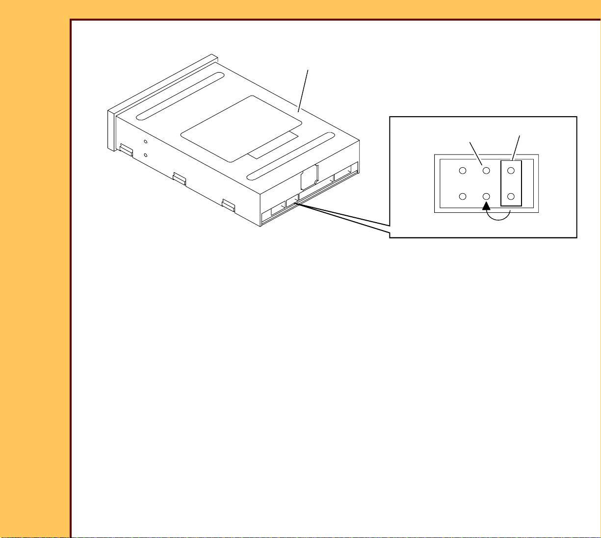
DVD WRITER
H195_0055BCA
H195_0055BC
4 Move the JUMPER to PIN 7 on the DVD WRITER.
PIN 7
JUMPER
Page 22
15DEC06
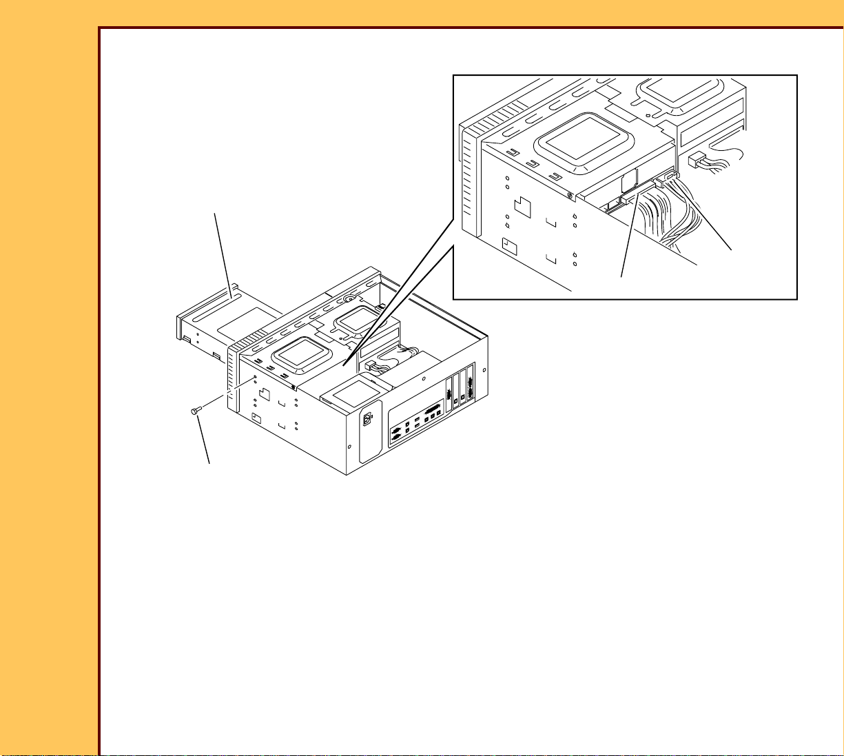
H195_0054HC
CABLE
POWER
IDE CABLE
2 SCREWS
DVD WRITER
H195_0054HCA
II4366-1
Page
22 of 91
INSTALLATION INSTRUCTIONS Installation
5 Install:
• DVD WRITER
• 2 SCREWS
6 Connect the CABLES:
• IDE
• POWER
7 Install the CPU COVER.
Page 23

INSTALLATION INSTRUCTIONS Installation
15DEC06
II4366-1
Page
23 of 91
Connecting the Power
Caution
Dangerous Voltage
1 Does your system have an ISOLATION TRANSFORMER installed?
Yes No
a. Connect:
• UPS POWER CABLE to the
ISOLATION TRANSFORMER
• ISOLATION TRANSFORMER
POWER CABLE to the power
source.
b. Continue with Step 2.
2 Connect the system to the network connection at the site.
a. Connect the UPS POWER CABLE to the
power source.
b. Continue with Step 2.
Page 24
INSTALLATION INSTRUCTIONS Installation
15DEC06
II4366-1
Page
24 of 91
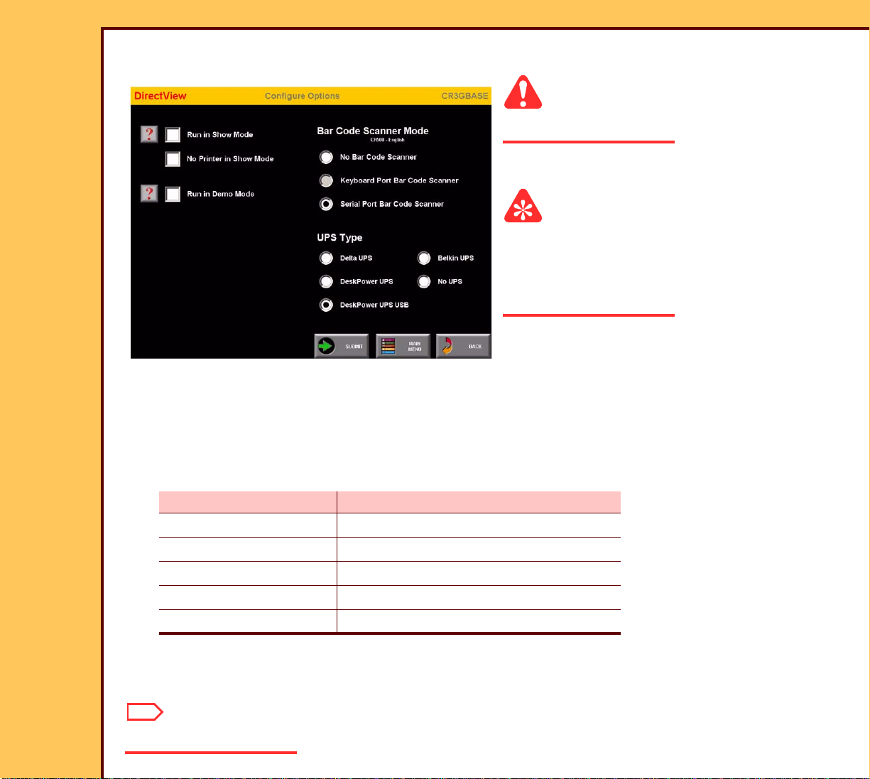
Setting the Configurations Options
Caution
Dangerous Voltage
1 Energize the system.
Important
For systems with software version ≥ 4.1, you
must have a “Session ID” for access to
“Service Functions” and “Diagnostics”. See
SERVICE BULLETIN 843.
2 From the main menu, click:
• [Ser vice Functions]
• [Configure Options]
• [Ser ial Port Bar Code Scanner]
3 Under the “UPS Type”, select the check box for the corresponding UPS installed in your
system:
Check Box UPS
Delta UPS Japan only
DeskPower UPS 650 VA - RS232 Port
DeskPower UPS USB 650 VA - USB Port
Belkin UPS Belkin UPS
No UPS No UPS used
4 If necessar y, under the “Bar Code Scanner Mode” select the corresponding check box.
5 Click [Submit].
Note
The system restarts.
Page 25

INSTALLATION INSTRUCTIONS Installation
15DEC06
II4366-1
Page
25 of 91
Doing the Setup
Checking the MIMDUI Configuration of the LOCALHOST
1 A t the main menu, click:
• [Ser vice Functions]
• [Ser vice Utilities]
• [Exit to Desktop]
2 Double-click the “MIMDUI” icon.
3 Select:
• Configure>Connect to MIM
• Configure>Destination
4 Check that “LOCALHOST” appears in the list of “Available Destinations”.
5 Select:
• [LOCALHOST]
• [Modify]
6 Check the following setting:
Field Parameter
Logical Name LOCALHOST
IP Address 127.0.0.1
Port Number 104
AE Title LOCALHOST
Response Message 130
Association Retry
Counter
“Modality LUT” on the SCU screen is
checked
1
Page 26

INSTALLATION INSTRUCTIONS Installation
15DEC06
II4366-1
Page
26 of 91
7 Is the information correct?
Yes No
Advance to Setting the Configuration of the DVD DRIVE. Continue with Step
Step 8.
8 Select Add>Store>Qualified.
9 Click:
• [AutoRad WS]
• [OK]
10 For:
• “Logical Name” type: LOCALHOST
• “IP Address” type: 127.0.0.1
11 Click [Next].
12 Type the following information for the Parameters:
Field Parameter
Port Number 104
AE Title LOCALHOST
Response Message 130
Association Retry
1
Counter
13 Click:
• [Next]
• [Next]
• [Next]
14 At the “SCU” screen, check that the “Modality LUT” check box is selected.
Page 27

INSTALLATION INSTRUCTIONS Installation
15DEC06
II4366-1
Page
27 of 91
15 Click:
• [Next]
• [Finish]
• [Close]
16 Select Connect>Disconnect.
17 If promp ted, insert the MIM BACKUP DISK.
18 Click [OK].
19 Select:
• Connect>Exit.
• Start>Shutdown>Restart
Adding the CD/DVD DESTINATION to the MIM
1 Log on to the ser vice menu.
2 A t the main menu, click:
• [Ser vice Functions]
• [Ser vice Utilities]
• [Exit to Desktop]
3 Check that “RNI” is running.
4 If “RNI” is not r unning:
a Select Start>Run.
b Type: rni.exe
c Click [OK].
5 Double-click the “MIMDUI” icon.
6 Select Configure>Connect to MIM.
7 Wait for the “MIMDUI” screen to appear.
Page 28
INSTALLATION INSTRUCTIONS Installation
15DEC06
II4366-1
Page
28 of 91
8 Select:
• Configure>Destination
• New>Store>Qualified
9 Select “AutoRad WS”.
10 Click [OK].
Page 29

15DEC06
II4366-1
Page
29 of 91
INSTALLATION INSTRUCTIONS Installation
11 For:
Field Name Type:
Logical Name: DVD/CD
IP Address: 127.0.0.1
12 Click [Next].
Page 30

15DEC06
II4366-1
Page
30 of 91
INSTALLATION INSTRUCTIONS Installation
Important
The “AE Title” must be typed “LOCALHOST”:
• one word with no spaces
• all uppercase letters
13 Type the following information for the parameters.
Field Parameter
Port Number: 104
AE Title: LOCALHOST
Association Retry Counter : 1
Response Message: 130
Page 31
INSTALLATION INSTRUCTIONS Installation
15DEC06
II4366-1
Page
31 of 91
14 Click:
• [Next] at the “Supported Items” screen
• [Next] at the “Formats” screen
• [Next] at the “Page Formatting” screen
15 At the “SCU” screen, check that the “Modality LUT” check box is selected.
16 Click:
• [OK]
• [Finish]
• [Close]
17 Select Connect>Disconnect.
18 Inser t the MIM BACKUP DISKETTE into the FLOPPY DRIVE.
19 To make a backup of the MIM configuration, click [OK].
Page 32

INSTALLATION INSTRUCTIONS Installation
15DEC06
II4366-1
Page
32 of 91
20 Select:
• Connect>Exit
• Start>Shutdown>Restart
21 Click [OK].
Setting the Configuration of the DVD DRIVE
1 Log on to the ser vice menu.
2 A t the main menu, click:
• [Key Operator Functions]
• [System Configuration]
• [Next]
• [Delivery Preferences]
• [CAD Workstation Configuration]
3 Select the “LOCALHOST” check box.
4 Click [SUBMIT].
Note
• If you are using DVD/CDs that are not formatted, you must format the DVD/CDs using
[DVD/CD Utilities] in the [Utility Menu].
• The Plextor SOFTWARE does not provide “Quick Format” for DVD+RWs.
Page 33

INSTALLATION INSTRUCTIONS Installation
15DEC06
II4366-1
Page
33 of 91
Instructing the Customer in Using CD/DVDs
Recommended Can Use
CD/DVD
“Archiving”
CD
Pati en t C D
“Archiving”
CD
Pati en t CD
CD-R X X X
CD-RW X X
DVD+R X X X
DVD+RW X X
Important
• You can use all styles of CD/DVDs for:
– “Archiving” CDs
– Patient CDs
• When making an “Archiving” CD, you must format the CD/DVD using the “Full Format”
option of the Roxio SOFTWARE.
• CD-R is recommended for patient CDs. CD-Rs have a minimum cost.
• DVD+R is recommended for “Archiving” CDs. DVD+Rs hold more images than CD-Rs.
• If a customer wants to write to a CD/DVD more than one time, CD-RW and DVD-RW can
be used.
• If the customer wants to “Archive” images to a CD/DVD and store the images for a long
time, the CD-R or DVD+R is recommended.
• For patient CDs, you do not have to format the CD/DVD.
1 Instr uct the customer to use the correct CD/DVD for the application.
Page 34

INSTALLATION INSTRUCTIONS Installation
15DEC06
II4366-1
Page
34 of 91
2 See the table below for the approximate quantity of images that can be stored on a CD/
DVD.
“Archiving” CD Patie nt CD
Average
Quantity of
Images
Viewer Software
Average
Quantity of
Images
CD/DVD Size
Approximate
Average
Image Size
CD-R 700 mB 10 mB 70 15 68
CD-RW
DVD+R 4700 mB 470 468
DVD+RW
Setting the Network User Interface
Important
The REMOTE ACCESS SERVICE (RAS) SERVER enables access to other CR 500
SYSTEMS or network equipment and provides the following IP addresses to the customer:
• RAS addresses are used only if the CR 500 SYSTEM has remote diagnostics for the
“Technical Suppor t Center” (TSC). An optional MODEM is installed on the CR 500
SYSTEM.
• The “Begin IP Address” and the “End IP Address” have a 2 number difference in
sequence.
• The same RAS IP address must be on every CR 500 SYSTEM at the customer’s site if
only one MODEM is used. This is necessary for the TSC to execute the application for the
CR 500 SYSTEM on other CR 500 SYSTEMS without a MODEM.
1 From the main menu, click:
• [Ser vice Functions]
• [Network Configurations]
Page 35

15DEC06
II4366-1
Page
35 of 91
INSTALLATION INSTRUCTIONS Installation
2 Enter:
• “Local IP Address”
• “Subnet Mask”
• “Default Gateway”
• “RAS IP Address Range”
3 Change the “Station Name”.
Note
The “Station Name” is the “Computer Name” and the “AE Title” of the CR 500 SYSTEM.
4 Obtain th e “NETWORK Speed/Duplex” information from the “System Administrator”.
5 Click [NETWORK Speed/Duplex].
6 En ter the information.
7 Click [Save Changes].
8 At the “Microsoft Inter net Explorer” screen, click [OK].
Note
The system boots again in approximately 5 minutes. Do not select any fields on the screen.
Page 36

INSTALLATION INSTRUCTIONS Installation
15DEC06
II4366-1
Page
36 of 91
9 At the main menu, click [Service Functions].
10 Check that the name given in Step 3 displays.
Setting the “Regional IP Parameters”
1 Click:
• [Applications Consultant]
• [Image Processing Preference Editor]
• [Revert Parameters]
2 In the “Image Processing Default Parameters” field, select the region.
3 Click [Set New IPL Defaults].
4 Select “Reset all parameters to factory defaults for all selected body parts and
projections”.
5 Click:
• [BACK]
• [Save All Parameters to Hard Drive]
• [BACK]
• [Continue Exit]
• [MAIN MENU]
Page 37

INSTALLATION INSTRUCTIONS Installation
15DEC06
II4366-1
Page
37 of 91
Setting the “Global Parameters”
1 From the main menu, click:
• [Key Operator Functions]
• [System Configuration]
2 Click:
• [NEXT]
• [NEXT]
• [Regional Settings]
Page 38

15DEC06
II4366-1
Page
38 of 91
INSTALLATION INSTRUCTIONS Installation
3 Enter:
• “Current Date & Time”
• “Time Zone” - if you change the “Time Zone”, you must also change the time.
• “Language”
4 Click:
• [SAVE CHANGES]
• [BACK]
• [Previous]
• [Delivery Preferences]
• [Default Values]
Page 39

15DEC06
II4366-1
Page
39 of 91
INSTALLATION INSTRUCTIONS Installation
5 Enter:
• “Default Hospital Name”
• “Default Hospital Address”
6 Click:
• [SAVE CHANGES]
• [BACK]
• [Delivery Options]
Page 40

15DEC06
II4366-1
Page
40 of 91
INSTALLATION INSTRUCTIONS Installation
7 Select:
• “Run in QA Mode”
• “After Delivering a Multi-Format Image, Update the Status of all Sub-Images to
Delivered”
Note
“Run in QA Mode” allows the customer to review all images before the images are sent to a
“Destination”.
Page 41

INSTALLATION INSTRUCTIONS Installation
15DEC06
II4366-1
Page
41 of 91
8 Click:
• [SAVE CHANGES]
• [BACK]
• [BACK]
• [NEXT]
• [Miscellaneous]
Important
Customer requirements determine the “Default Body Part” and “Default Projection”.
9 Check:
• “Default Body Part” - “Chest”
• “Default Projection” - “AP”
Page 42

INSTALLATION INSTRUCTIONS Installation
15DEC06
II4366-1
Page
42 of 91
10 Click:
• [SAVE CHANGES]
• [BACK]
• [System Maintenance Defaults]
11 Check that the values are:
• 90%
• 70%
• 30
12 Click:
• [SAVE CHANGES]
• [BACK]
• [MAIN MENU]
• [UTILITY MENU]
• [SYSTEM Shutdown]
Page 43

INSTALLATION INSTRUCTIONS Installation
15DEC06
II4366-1
Page
43 of 91
13 S elect “Shutdown/Power Off”.
14 Click [OK].
Caution
Dangerous Voltage
15 Energize the system.
Setting the MONITOR
1 Deter mine what MONITOR you have.
LCD DISPLAY CRT
Continue with Step 2. Advance to Enabling Full Resolution
Image Viewing.
2 Click:
• [Key Operator Functions]
• [System Configuration]
• [NEXT]
• [NEXT]
• [Configure Monitor]
3 Click on the MODEL of MONITOR for
your system.
4 Select the “Ambient Light” level.
5 Click:
• [Submit]
• [MAIN MENU]
Page 44

INSTALLATION INSTRUCTIONS Installation
15DEC06
II4366-1
Page
44 of 91
Enabling Full Resolution Image Viewing
Important
The system is set with this feature enabled. Do this procedure only to disable this feature.
1 Click:
• [Key Operator Functions]
• [System Configuration]
• [CR Display Configuration]
2 Select the “Enable Full Res Image Viewing” field.
3 Click:
• [SAVE CHANGES]
• [MAIN MENU]
Installing and Setting the Optional Features
Important
It might be necessary to enable upgrade options for each CR 500 SYSTEM.
1 From the main menu, click:
• [Key Operator Functions]
• [System Configuration]
• [Option Registration]
2 Inser t the correct OPTIONS DISK into the computer.
3 Click [Add Upgrade Options].
Note
A mark displays next to the options installed from the FLOPPY DISK.
Page 45

15DEC06
II4366-1
Page
45 of 91
INSTALLATION INSTRUCTIONS Installation
4 Make a call to the “Technical Support Center” to check that the “Option Registration” is
correct.
5 Do Step 2 - Step 3 again for other options.
6 Click [OK].
Page 46

INSTALLATION INSTRUCTIONS Installation
15DEC06
II4366-1
Page
46 of 91
Setting the HIS/RIS Parameters
“Polling” Option
Important
• Use this procedure if the system is connected to HIS/RIS.
• “Polling” is an option purchased by the customer.
• The values selected in this screen determines the “polling” of all patient information for
this “Station” from the “Broker”.
1 From the main menu, click:
• [Key Operator Functions]
• [System Configuration]
• [HIS/RIS - Broker Configuration]
• [Polling Configuration]
Page 47
15DEC06
II4366-1
Page
47 of 91
INSTALLATION INSTRUCTIONS Installation
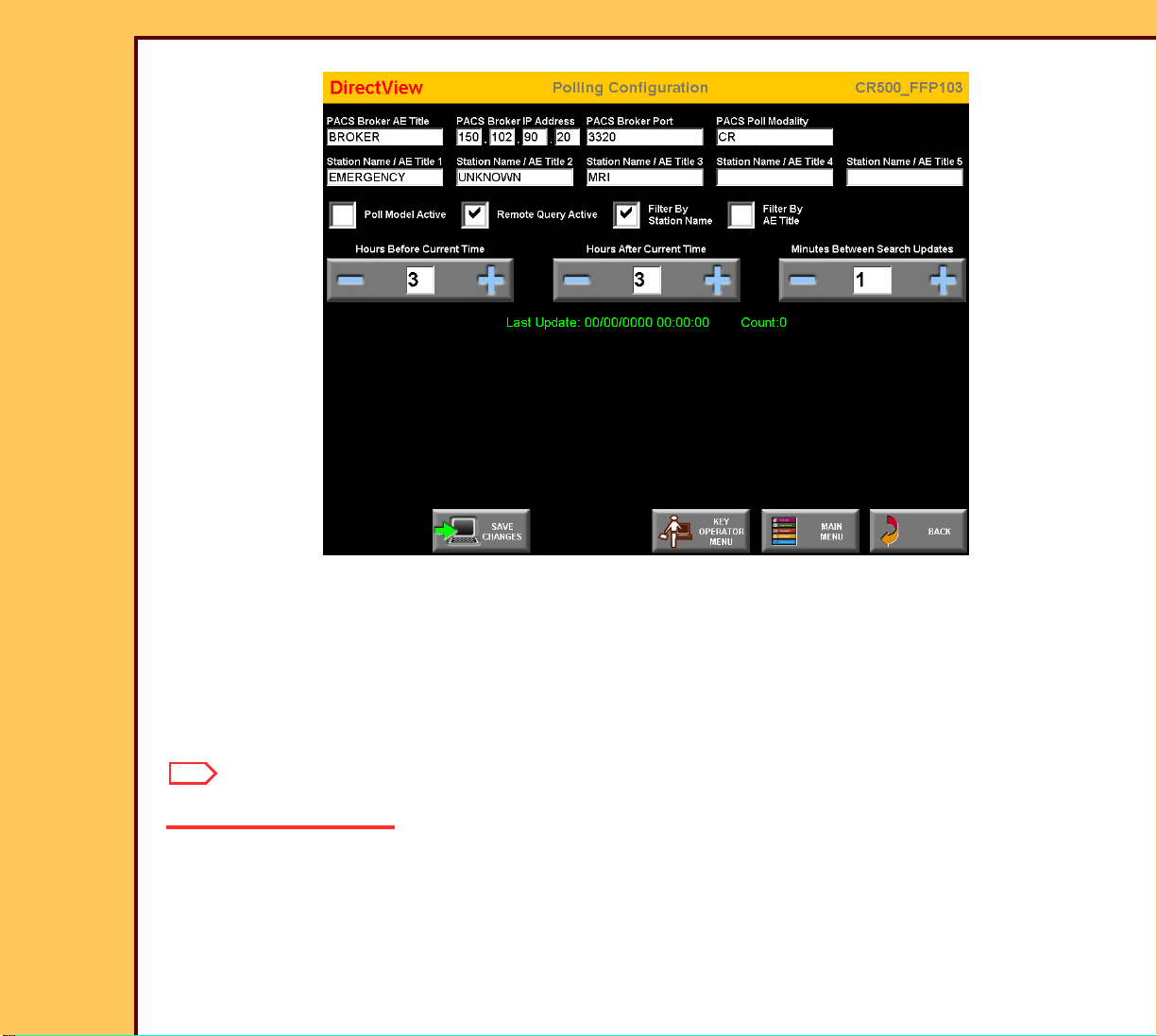
2 Enter:
• “PACS Broker AE Title”
• “PACS Broker IP Address”
• “PACS Broker Port” - obtain the port number from the “System Administrator”
• “Station Name” - obtain the names from the “System Administrator”
Note
A maximum of 5 “Station Names” can be selected.
3 Select:
• “Filter By Station Name”
• “Filter By AE Title”
Page 48

INSTALLATION INSTRUCTIONS Installation
15DEC06
II4366-1
Page
48 of 91
4 Select or clear the check box for the options purchased by the customer:
“Polling” Only “Polling” and “Remote Query” “Remote Query” Only
a. Clear “Remote Quer y
Active”.
b. Select the “Poll Model
Active”.
Important
Select:
• “Poll Model Active”
• “Remote Quer y Active”
a. Select “Remote Quer y
Active”.
b. Clear the “Poll Model
Active”.
If “Poll” is selected, the “Minutes Between Search Updates” could be changed to 720 minutes
because the “Broker” will automatically send any new patient information.
5 Check the default times
• “Hours Before Current Time” - “3”
• “Hours After Current Time” - “3”
• “Minutes Between Search Updates” - “10”
6 Click:
• [SAVE CHANGES]
• [BACK]
• [Push Configuration]
Page 49

INSTALLATION INSTRUCTIONS Installation
15DEC06
II4366-1
Page
49 of 91
“Push” Option
Important
The “Push” function is determined by the features of the “Broker”.
7 Check the “Verify and Validate” database at the “Technical Support Center” to identify if
the “Broker” has the “Push” function.
8 If the customer wants the “Push” option, select the “Push Connection Active” check box
at each CR SYSTEM.
9 Enter a value between 1025 - 65535 into the “PACS Push Port Number” field.
Note
• The default number is 5401.
• The same por t number can be used for a number of CR 500 SYSTEMS.
Page 50

INSTALLATION INSTRUCTIONS Installation
15DEC06
II4366-1
Page
50 of 91
10 Enter any name into the “PACS Push AE Title” field, except the computer name.
11 Record all the data from the “Push” screen.
Note
The following “events” from the “Dicom Event Notification” must be “filtered” for the PACS
PORT MODALITY of the CR 500 SYSTEM:
• “Study Star ted”
• “Study Updated”
• “Study Completed”
12 Provide the information from the “Push” screen to the “System Administrator” for the
“Broker” equipment.
Adding a PRINTING DEVICE
Important
• For systems with Software Version ≥ 4.1, you must have a “Session ID” for access to
“Service Functions” and “Diagnostics”. See SERVICE BULLETIN 843.
• Use the KEYBOARD and MOUSE for this procedure.
1 From the main menu, click:
• [Ser vice Functions]
• [Shutdown]
• [Exit to Desktop]
2 Wait for the software shutdown.
3 Double-click the “MIMDU” icon.
4 For the password, type: service
5 Click [OK].
6 Select Connect>Passthrough.
Page 51

INSTALLATION INSTRUCTIONS Installation
15DEC06
II4366-1
Page
51 of 91
7 Enter the IP address of the CR 500 SYSTEM.
8 Click [OK].
9 At the “MIM Ser vice Application” screen, click:
• [Configure]
• [Destination]
Important
“HARD DISK” is the displayed “Destination”. The parameters must not be changed. “HARD
DISK” must not be deleted.
10 At the “Installed Destinations” screen, click:
• [Add]
• [Print]
• [Network]
• [Qualified]
Page 52

15DEC06
II4366-1
Page
52 of 91
INSTALLATION INSTRUCTIONS Installation
11 At the “Choose a New Network Pr int
Destination” screen, select the correct
PRINTER from the list.
12 Click [OK].
13 At the “General” screen, enter the
information provided by the “Senior
Project Manager”.
14 Click [Next].
15 Make a call to the TSC or the Countr y
Specialist if an “unqualified” PRINTER
is used.
16 At the “General” screen, enter the
correct parameters.
17 Click [Next].
Page 53

15DEC06
II4366-1
Page
53 of 91
INSTALLATION INSTRUCTIONS Installation
18 In the “Media” screen, enter the correct:
• “Size”
• “Columns”
• “Rows”
• “Media Type”
Important
• For the configuration of a PRINTER that
has 2 or more film sizes, each film size
must be set with a separate
“Destination”.
• The numbers that the “Media” screen
displays might not match the numbers
displayed in the screen.
19 In the “Media” screen, select all the
types that the customer uses.
20 Click [Next].
Note
• Only change the default numbers for
“qualified Destinations” when instructed
by the TSC or the Country Specialist.
• If an item does not have a mark in the
“Media” or “Supported Items” screens,
the customer does not have access to
that item.
Page 54

15DEC06
II4366-1
Page
54 of 91
INSTALLATION INSTRUCTIONS Installation
21 In the “DICOM” screen, enter the
correct parameters.
22 Click [Next].
23 At the “Suppor ted Items” screen, check
that the correct items are selected.
24 Click [Next].
Page 55

15DEC06
II4366-1
Page
55 of 91
INSTALLATION INSTRUCTIONS Installation
25 At the “Inter polation” screen, check that
the correct items are selected.
26 Click [Next].
27 At the “Format Types” screen, check
that the correct items are selected.
28 Click [Next].
Page 56

15DEC06
II4366-1
Page
56 of 91
INSTALLATION INSTRUCTIONS Installation
29 At the “Formatting” screen, check that
the correct items are selected.
30 Click [Next].
31 At the “Image Processing” screen,
check that the correct items are
selected.
32 Click [Next].
Page 57
15DEC06
II4366-1
Page
57 of 91
INSTALLATION INSTRUCTIONS Installation
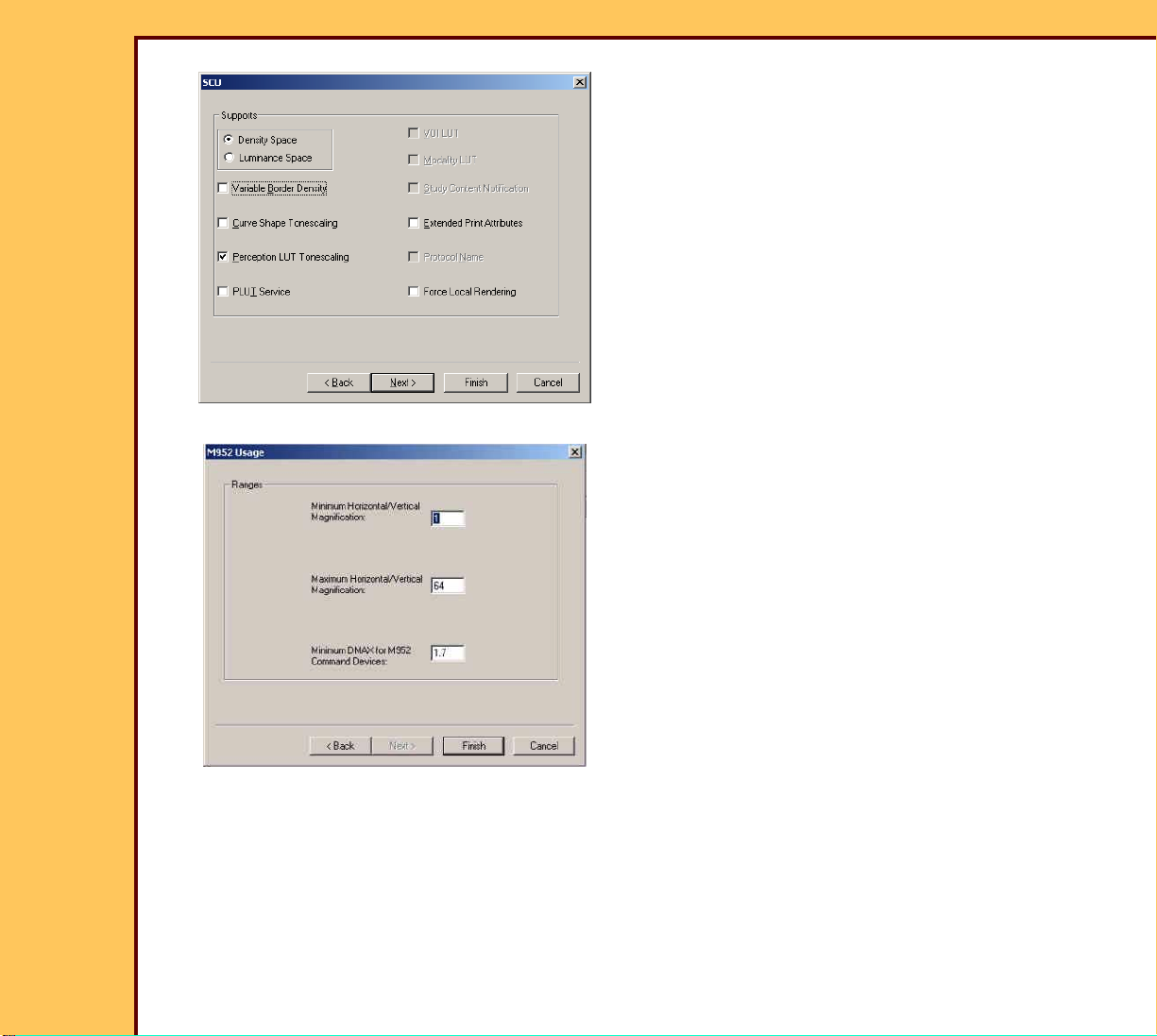
33 At the “SCU” screen, check that the
correct items are selected.
34 Click [Next].
35 At the “M952 Usage” screen, check that
the correct items are selected.
36 Click [Finish].
37 Check that the configuration of the “Destination” is correct:
a At the “Ser vice Application” screen, select Diagnostics>Network.
b Select:
• “Ping”
• “DICOM Echo”
• “Run”
Page 58

INSTALLATION INSTRUCTIONS Installation
15DEC06
II4366-1
Page
58 of 91
c Enter the information for the new “Destination”:
• “Port Number”
• “IP address”
• “AE Title”
d Click [OK].
e Does “Passed” display?
Yes No
Click [Cancel] from the
“Network Diagnostics”
screen.
Check:
• “Destinations” are correct. See Step 13 - Step 18.
• Customer’s network is operating correctly.
• PRINTER is energized and set to receive
information from the CR 500 SYSTEM.
38 To add more “Destinations”, do Step 9 - Step 27 again. See “Destination” Parameters:
Names, Addresses, and DICOM Information.
39 If all “Destinations” are set, at the “Ser vice Applications” screen click:
• [Connect]
• [Disconnect]
40 At the prompt, inser t the MIM DISK stored at the customer site.
41 Click [OK] to store the data to the disk.
42 Close the “MIM Ser vice Applications” screen.
43 Click [Restar t].
44 At the “Login” screen, type for:
• “User Name” - service
• “Password” - service
Page 59

INSTALLATION INSTRUCTIONS Installation
15DEC06
II4366-1
Page
59 of 91
45 From the main menu, click:
• [Key Operator Functions]
• [System Configuration]
• [Profile Destination Configuration]
• [New Profile]
46 Check that the new “Destination” names are correct. If necessary, use the tables below
to define the “Destination” parameters.
47 From the main menu, click:
• [Key Operator Functions]
• [System Calibration]
48 From the “System Calibration” screen, send the SMPTE Test Pattern to a Printing
Device.
Important
• Only change the default numbers for qualified “Destinations ”when instructed by the TSC.
• If a mar k does not display in the “Supported Item” or “Media Info” check box, the customer
does not have access to that item.
Table 4 “Destination” Parameters: Names, Addresses, and DICOM Information
Item Description Value
Logical
Name
IP Address The site-defined address that identifies the
Database
Name
The site-defined name that you must enter for a
Destination. The CR 500 SYSTEM displays this
name when the operator selects a Destination.
Destination on the network. 2 or more
Destinations must not
have the same IP
address.
The name of the Destination selected from the
Destination database. This field is view only.
1 - 9 letters and/or numbers
with no spaces.
Underscores are allowed.
4 fields of 1 - 254. Each
field is separated by a
period. For example:
149.110.98.10
1 - 13 letters and/or
numbers.
Page 60

15DEC06
II4366-1
Page
60 of 91
INSTALLATION INSTRUCTIONS Installation
Item Description Value
Node ID The number that identifies the CPOI in the laser
1 - 7
PRINTER. This field is view only.
Model The model of the Destination. The system uses
this data to optimize the page format check for
the Destination. This field is view only.
Memory The number of megabytes (MB) of memory in
the Destination. The system uses this value to
check the format. This value is site defined. The
user must enter a value in this field.
Image Pad The number of pixels reserved around the
border of an image in the x and y direction. The
system uses this value to check the format.
Minimum
Vertical
Separation
Minimum
Horizontal
Separation
The number of rows that separate the image
bands in the vertical direction. The system uses
this value to check the format.
The number of rows that separate the image
bands in the horizontal direction. The system
uses this value to check the format.
1 - 99
Only change the default
numbers for qualified
Destinations when instructed
by the TSC or the Country
Specialist.
0 - 10
Only change the default
numbers for qualified
Destinations when instructed
by the TSC or the Country
Specialist.
0 - 10
Only change the default
numbers for qualified
Destinations when instructed
by the TSC or the Country
Specialist.
0 - 10
[DICOM
INFO]
Select this to display the DICOM information
indicated in this table.
Protocol The protocol used to provide communication
with the Destination.
N/A
DICOM 3.0
Page 61

15DEC06
II4366-1
Page
61 of 91
INSTALLATION INSTRUCTIONS Installation
Item Description Value
Service
The service class provided by the Destination. Print
Class
Port
Number
The port number of the Destination that the
system uses to provide a connection to send
1024 - 32767; default 5040
and receive DICOM messages.
AE Title The Application Entity (AE) Title defines the Destination application that the
system must use for successful DICOM communications. The field width for
this parameter is 1 - 16 letters and/or numbers. N_Event Reporting (NER) in
the AE Title enables the reporting of the Destination status:
• N_Event Repor ting (NER)
• “printer name” or “NER_pr inter name” sends the image to the defined
PRINTER when multiple PRINTERS of the same type are connected to the
Kodak Digital ScienceTM DICOM PRINT SPOOLER, Model 100
• “2180” of “NER_2180” sends the image to the first installed PRINTER on
the PIU that is a Kodak Ektascan 2180 LASER PRINTER, Kodak Ektascan
1120 LASER PRINTER, and the Kodak Ektascan LASER PRINTER, Model
100 XLP
• “2180/1” or “NER_2180/1” sends the documents to the first installed 2180
LASER PRINTER on a DPS, and the films are placed in BIN #1.
[Response
Message
Timer]
Select this to define the length of time to wait for a response after sending a
message. Used for DICOM communication. The configuration can be changed
at each site. Only change the default numbers for qualified Destinations when
instructed by the TSC or the Country Specialist.
Page 62

INSTALLATION INSTRUCTIONS Installation
15DEC06
II4366-1
Page
62 of 91
Table 5 “Destination” Parameters: Supported Items
Item Description Value
[Supported Items] Select this to display the supported features indicated
N/A
in th is tabl e.
Aspect Ratio Mix
on Page
Aspect Ratio Mix in
Row
Will the Destination support mixed aspect ratios on the
same page?
Will the Destination support mixed aspect ratios on the
same row?
Yes , No
Yes , No
Collation Will the Destination support collation? Yes, No
Color Will the Destination suppor t 3 color, Red, Green, Blue
Yes , No
(RGB) printing?
Color/Grayscale
Same Page
Common Text Will the Destination support common text band? The
Will the Destination support 3 color (RGB) pr inting on
the same page?
Yes , No
Yes , No
system uses this value to check the format.
Curve Shape
Image Basis
Custom Formats Will the Destination suppor t custom formats 101 and
Will the Destination support changing the cur ve shape
on a image-by-image basis?
Yes , No
Yes , No
102? The system uses this value to check the format.
Decimation Will the Destination decrease the image size to fit on
Yes , No
the media?
Edge
Will the Destination support edge enhancement? Yes, No
Enhancement
Grayscale Will the Destination suppor t grayscale printing? Yes, No
Image Size Mix in
Std Fmt
Image Size Mix in
Row
Media Bin Default Will the Destination support more than one media size
Will the Destination support mixed image sizes on a
standard format page, “2-up”, “4-up”, “6-up”, “9-up”?
Will the Destination support multiple size images in the
same row?
Yes , No
Yes , No
Yes , No
at the same time?
Page 63

15DEC06
II4366-1
Page
63 of 91
INSTALLATION INSTRUCTIONS Installation
Item Description Value
Page Annotation Will the Destination support page annotation? This is a
Yes , No
frequent requirement for “Requested Image Size”.
Pivot Density Will the Destination support pivot density? Yes, No
Print Quality Will the Destination support more than one pr inting
resolution?
Remote Image
Will the Destination support remote image deletion? Yes, No
Deletion
Requested Image
Will the Destination support requested image size? Yes, No
Size
Requested Size
Will the Destination support requested image scale? Yes, No
Scale
Requested Size
Mix on Page
Requested Size
Mix in Row
Will the Destination support more than one requested
image sizes on the same page?
Will the Destination support more than one requested
image sizes in the same row?
Rotation Will the system support full page rotation? The system
uses this parameter to check the format.
Row Symmetric
Formats
The row symmetric formats that are allowed by the
Destination. The row symmetric formats have a line of
symmetry only in the vertical direction. The system
uses this parameter to check the format.
Slide Format The slide format that is allowed by the Destination.
The system uses this parameter to check the format.
Yes , No
Yes , No
Yes , No
Yes , No
Yes , No
Yes , No
Super Slide Format The super slide format that is allowed by the
Destination. The system uses this parameter to check
the format.
Yes , No
Page 64

15DEC06
II4366-1
Page
64 of 91
INSTALLATION INSTRUCTIONS Installation
Item Description Value
Trim The trim that is allowed by the Destination. Yes, No
Interpolation
Methods
The interpolation methods that are allowed by the
Destination.
Bilinear,
Cubic Spline,
Cubic
Convolution 2,
Cubic Con. 3,
Replication,
No
Magnification
Table 6 “Destination” Parameters: Media Information
Item Description Range
[Media Info] Select this to display the media information indicated in this
N/A
table.
Media Size The media size that is allowed by the Destination. 35 x 43 cm
35 x 35 cm
11 x 14 in.
11 x 11 in.
10 x 12 in.
8.5 x 11 in.
8 x 10 in.
4 x 6 in.
A4
Media Types The media types that are allowed by the Destination.
Media types are selected for each media size. “Any”
indicates that the Destination will use the media type that
matches the media size selected. “Reflective” and
“Transparent” are allowed for color printing. The CR 500
SYSTEM does not allow color printing.
Any, Blue, Clear,
Reflective P aper,
Transparent Film
Page 65

15DEC06
II4366-1
Page
65 of 91
INSTALLATION INSTRUCTIONS Installation
Item Description Range
Maximum
Columns
The maximum number of printable pixels in the x direction
for the media size. Maximum columns are selectable for
1 - 9999
each media size. The system uses this parameter to check
the format.
Maximum
Rows
The maximum number of printable pixels in the y direction
for the media size. Maximum rows are selectable for each
1 - 9999
media size with or without common text. The system uses
this parameter to check the format.
Adding a STORAGE DEVICE
Important
• For systems with Software Version ≥ 4.1, you must have a “Session ID” for access to
“Service Functions” and “Diagnostics”. See SERVICE BULLETIN 843.
• Use the KEYBOARD and the MOUSE for this procedure.
1 From the main menu click:
• [Ser vice Functions]
• [Exit to Desktop]
2 Double-click the “MIMDUI” icon.
3 For the password, type: service
4 Click [OK].
5 Select Connect>Passthrough.
6 Enter the IP address of the CR 500 SYSTEM or type: 127.0.0.1
7 Click [OK].
8 At the “MIM Ser vice Application” screen, click:
• [Configure]
• [Destination]
Page 66

15DEC06
II4366-1
Page
66 of 91
INSTALLATION INSTRUCTIONS Installation
Important
• “HARD DISK” is the displayed “Destination”.
• The parameters must not be changed.
• Do not delete “HARD DISK”.
9 At the “Installed Destinations” screen, click:
• [Add]
• [Store]
• [Qualified]
Note
You must make a call to the TSC or the Country Specialist for questions on parameters for
the STORAGE DEVICE.
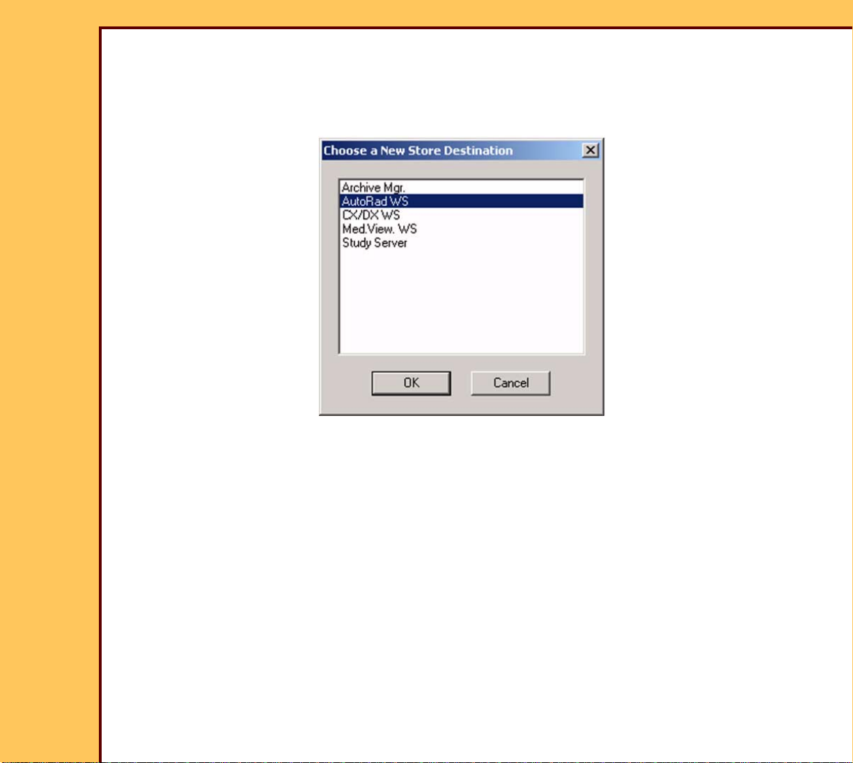
10 At the “Choose a New Store
Destination” screen, select a
“Destination”.
11 Click [OK].
Page 67

15DEC06
II4366-1
Page
67 of 91
INSTALLATION INSTRUCTIONS Installation
12 At the “General” screen, enter :
• “Logical Name”
• “IP Address”
13 Click [Next].
14 In the “DICOM” screen, enter the
correct information:
• “Port Number”
• “AE Title”
• “Association Retr y Counter”
• “Response Message”
15 Click [Next].
Page 68

15DEC06
II4366-1
Page
68 of 91
INSTALLATION INSTRUCTIONS Installation
16 At the “Suppor ted Items” screen, enter
the correct information.
17 Click [Next].
18 At the “Format Types” screen, enter the
correct information.
19 Click [Next].
Page 69

15DEC06
II4366-1
Page
69 of 91
INSTALLATION INSTRUCTIONS Installation
20 At the “Page Formatting” screen, enter
the correct information.
21 Click [Next].
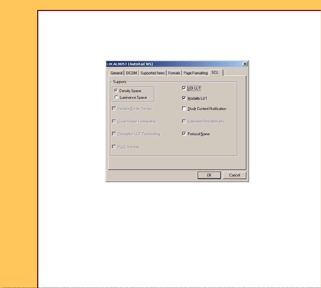
Important
• The “SCU” screen defaults to “Density
Space”.
• All WORKSTATIONS are set to
“Luminance Space”.
22 At the “SCU” screen, enter the correct
information.
23 Click [Finish].
24 Are you adding more “Store
Destinations”?
Yes No
Do Step 9 -
Click [Close].
Step 23 again.
25 At the “Installed Destinations” screen,
click:
• [Add]
• [Store]
• [Qualified]
Page 70

INSTALLATION INSTRUCTIONS Installation
15DEC06
II4366-1
Page
70 of 91
26 Check that the configuration of the “Destination” is correct.
a At the “Ser vice Application” screen, select Diagnostics>Network.
b Select:
• “Ping”
• “DICOM Echo”
• “Run”
c Enter the information for the new “Destination”.
• “IP Address”
• “AE Title”
• “Port Number”
d Click [OK].
e Does “Passed” display?
Yes No
Advance to Step g. Continue with Step f.
f Check:
• “Destinations” are correct. See Step 12 - Step 14
• Customer’s network is operating.
• STORAGE DEVICE is energized and is set to receive information from the
CR 500 SYSTEM.
g Select “Cancel” from the “Network Diagnostics” screen.
27 If all “Destinations” were set, from the “Ser vice Applications” screen click:
• [Connect]
• [Disconnect]
28 At the prompt, remove the MIM DISK.
29 Store the MIM DISK at the customer site.
30 Close the “Ser vice Applications” screen.
Page 71

INSTALLATION INSTRUCTIONS Installation
15DEC06
II4366-1
Page
71 of 91
31 Click the “Restar t” icon.
32 From the main menu, click:
• [Key Operator Functions]
• [System Configuration]
• [Profile Destination Configuration]
33 Select “Default”.
34 Click [Modify Existing Profile].
35 Add the “Default Destination”.
36 Click:
• [Save Profile]
• [MAIN MENU]
Page 72

INSTALLATION INSTRUCTIONS Installation
15DEC06
II4366-1
Page
72 of 91
Enabling the BAR CODE READER
Country Code
1 From the main menu, click:
• [Key Operator Functions]
• [System Configuration]
2 Click [Next].
3 Select Bar Code Configuratio n>Set Country Code.
Note
• A list of countr ies displays.
• The BAR CODE READER is enabled for the U.S. at the factory.
4 Select the correct option from the list.
5 Click:
• [BACK]
• [Program Bar Code Scanner]
• [CONFIG COUNTRY CODE]
Note
The bar codes display.
6 Scan the BAR CODE with the BAR CODE READER in sequence from the top of the
screen to the bottom of the screen.
7 Click [BACK].
Page 73

INSTALLATION INSTRUCTIONS Installation
15DEC06
II4366-1
Page
73 of 91
Code 39 Full ASCII Mode
Important
You must set the configuration for Code 39 Full ASCII only if necessary.
8 Obtain the mode information from the “System Administrator”.
9 Click [Code 39 Full ASCII Mode].
10 Scan one of the correct BAR CO DES with the BAR CODE READER:
• “Code 39 Full ASCII ON”
• “Code 39 Full ASCII OFF”
11 Click [BACK].
Automatic Trigger
Important
• “Automatic Tr igger” indicates that the BAR CODE READER is continually energized.
• “Manual Trigger” indicates that the BAR CODE READER operates when the TRIGGER is
actuated.
12 C lick [CONFIG AUTO TRIGGER].
13 Select “Automatic” or “Manual”.
14 Click:
• [BACK]
• [CONFIG PREFIX/SUFFIX]
15 Scan all the bar codes in sequence with the BAR CODE READER.
16 Click [NEXT].
17 Scan all the bar codes with the BAR CODE READER.
Page 74

INSTALLATION INSTRUCTIONS Installation
15DEC06
II4366-1
Page
74 of 91
18 Click:
• [BACK]
• [BACK]
Checking the BAR CODE READER
19 Click [BAR CODE CONFIGURATION].
20 Scan a TEST BAR CODE with the BAR CODE READER to check for correct operation
of the BAR CODE READER.
21 Click [MAIN MENU].
Page 75

INSTALLATION INSTRUCTIONS Installation
15DEC06
II4366-1
Page
75 of 91
Storing the Setup Data
1 From the main menu, click:
• [Key Operator Functions]
• [System Configuration]
• [SAVE ALL CONFIGS]
2 Select “Floppy”.
3 Click [OK].
Page 76

INSTALLATION INSTRUCTIONS Installation
15DEC06
II4366-1
Page
76 of 91
Installing the Kodak DirectView REMOTE OPERATIONS PANEL (ROP)
1 Disconnect the CR 500 SYSTEM from the “Hospi tal Network”.
2 Install the ROP. See:
Publication Publication No.
INSTALLATION INSTRUCTIONS for the Kodak DirectView REMOTE
OPERATIONS PANEL for the Kodak DirectView CR 500 SYSTEM
3 Connect:
• CR 500 SYSTEM to the “Hospital Network”
• ROP to the “Hospital Network”
Setting the Configurations for the ROPs
1 Do the “Enable File Sharing” on all the ROPs.
Caution
Dangerous Voltage
2 Energize the ROPs.
6F1562
3 Identify the pr imary system for the configuration of the ROPs.
Note
The configuration can have a maximum of 10 ROPs on the network to the primary system.
Page 77

INSTALLATION INSTRUCTIONS Installation
15DEC06
II4366-1
Page
77 of 91
4 Do the configuration for:
• ROPs from any CR 500 SYSTEM to provide communication with the other CR 500
SYSTEMS
• all of the configurations from the same system
Note
The hardware available at the time of the installation determines the hardware and IP
address. The example of the setup for more than one ROP is the setup of the primary CR
500 SYSTEM.
Page 78

INSTALLATION INSTRUCTIONS Installation
15DEC06
II4366-1
Page
78 of 91
Setting the Configuration for the ROP to More than One CR SYSTEM
Important
The following graphic uses “CR 3 (primar y)” to set the communication with CR 1, CR 2 and
CR 3.
ROPROP
IP 192.168.0.18
IP 192.168.0.15
IP 192.168.0.16 IP 192.168.0.17
IP 192.168.0.19
CR 2CR 1
CR 3
(primary)
1 From the main menu, select:
• [Key Operator Functions]
• [System Configuration]
• [Next]
• [Exter nal Devices]
• [Kodak Remote Operations Panel Setup]
Note
The “Remote Operations Panel IP Addresses” screen displays.
H195_9002AC
Page 79

INSTALLATION INSTRUCTIONS Installation
15DEC06
II4366-1
Page
79 of 91
Installing the Kodak REMOTE PATIENT DATA ENTRY STATION
Important
• The site must not use the “Dynamic Host
CR 500
SYSTEM
IP 192.168.0.30
Control Protocol” (DHCP). DHCP will
change the IP address of the Kodak
REMOTE PATIENT DATA ENTRY
STATION (RPDES) or REMOTE
OPERATIONS PANEL (ROP) with the
following conditions:
RPDES RPDES
RPDES
– “Site system shutdown”
IP 192.168.0.26
IP 192.168.0.28IP 192.168.0.27
– “Site boot”
– “Site license expiration”
H195_9001AC
• An RPDES must have an IP address that
does not change. If the configuration of
the computer uses DHCP, the connection
to the CR 500 SYSTEM will be deleted
when the computer boots.
• The RPDES is an option purchased by
the customer.
• The RPDES enables communication
between the customer’s computer and
the CR 500 SYSTEM for entering patient
data.
• This option allows a maximum setup of
10 RPDES into the database of the
CR 500 SYSTEM.
Page 80

INSTALLATION INSTRUCTIONS Installation
15DEC06
II4366-1
Page
80 of 91
1 Check the following before you do this procedure:
• The CR 500 SYSTEM must be connected to the site network.
• The computer must have Microsoft INTERNET EXPLORER SOFTWARE 6.0 or higher
installed and Windows 98 or Windows NT OPERATING SYSTEM.
• The RPDES option must be actuated from the OPTIONS DISK.
2 From the main menu, select:
• [Key Operator Functions]
• [System Configuration]
• [Option Registration]
3 Inser t the OPTIONS DISK into the CR 500 SYSTEM.
4 Install the RPDES option through the “Option Registration” screen.
5 Click [Add Upgrade Options].
Page 81

INSTALLATION INSTRUCTIONS Installation
15DEC06
II4366-1
Page
81 of 91
Setting the Configuration for the Remote Key Operator
1 From the main menu, click:
• [Key Operator Functions]
• [System Configuration]
• [NEXT]
• [Exter nal Devices]
• [Remote Key Operator]
2 Type the IP address for the computer.
3 Click:
• [SAVE CHANGES]
• [BACK]
Page 82

INSTALLATION INSTRUCTIONS Installation
15DEC06
II4366-1
Page
82 of 91
Setting the Configuration for the RPDES
1 From the main menu, click:
• [Key Operator Functions]
• [System Configuration]
• [NEXT]
• [Exter nal Devices]
• [Remote Patient Data Entry Station]
2 Type the IP address for the computer.
3 Click [SAVE CHANGES].
Page 83

INSTALLATION INSTRUCTIONS Installation
15DEC06
II4366-1
Page
83 of 91
Operating the RPDES
1 At the computer, double-click the “Internet Explorer” icon.
2 At “http://”, type the IP address for the CR 500 SYSTEM.
3 Press [Enter].
4 Add the address to the “Favorites” menu.
Caution
If you click [Submit] without entering information, the following displays:
5 Enter the patient information and click [Submit].
Page 84

INSTALLATION INSTRUCTIONS Installation
15DEC06
II4366-1
Page
84 of 91
Making a SHORTCUT for the RPDES
1 Select New>Shortcut.
2 Click [Browse] and locate the “IEXPLORE.exe” file.
Example: “C:\Program Files\Plus!\MicrosoftInternet\IEXPLORE.EXE”
Important
The Microsoft INTERNET EXPLORER “-k” option allows the INTERNET EXPLORER program
to operate in “full-screen” mode. If you do not want to operate in “full-screen” mode, do not
use “-k ” in Step 3.
3 Add the IP address for the CR 500 SYSTEM to the end of the line.
Example:
“C:\Program Files\Plus!\MicrosoftInternet\IEXPLORE.EXE -k http://129.126.6.62/RPDES”
4 To exit when in “full-screen” mode, press [Ctrl] + [W].
Note
The IP address for the CR 500 SYSTEM in this example is 129.126.6.62.
5 Click [Next].
6 Select a name for the new SHORTCUT.
7 Click [Finish].
8 Double-click the “SHORTCUT” icon to check that it operates correctly.
9 P ress [Ctrl] + [W] to exit.
Page 85

INSTALLATION INSTRUCTIONS Installation
15DEC06
II4366-1
Page
85 of 91
Setting the “User Name” and “Password”
Important
You must set the “User Name” and “Password” for all users on site.
1 At the “Login” screen, type for:
• “User Name” - SA
• “Password” - SA
2 Click [Enter].
3 Obtain the password from the System Administrator (SA). If the SA is not on site,
type: SECURITY
4 At the “Change Password” screen, type:
• “Current Password” - SA
• password obtained from Step 3 for the “New Password”
5 Click:
• [Save Changes]
• [User Configuration]
• [Create New User]
6 At the “Add New User” screen, type for:
• “User Name” - AC
• “Password” - 333333
• “Full Name” - Kodak Applications Consultant
• “Employee Number” - 123456
7 Select “Ap plications Consultant” for “Role”.
Page 86

INSTALLATION INSTRUCTIONS Installation
15DEC06
II4366-1
Page
86 of 91
8 Click:
• [Save Changes]
• [OK]
9 Do Steps 6 - 8 for all other users on site.
10 Click:
• [Back]
• [Back]
• [Logout]
11 At the “Login” screen, type for:
• “User Name” - AC
• “Password” - 333333
12 Click [Login].
Important
• The default password length configuration is 6 digits.
• If your password length configuration is:
– more than 6 digits, you must type the number 5 at the end for the additional digits
– less that 6 digits, you must type the corresponding digits up to the password length
Example:
• for a 10-digit password length configuration, type: 3305455555
• for a password length configuration of less than 6 digits, type: 3305
13 At the “Change Password” screen, type for:
• “Current Password” field - 333333
• “New Password” field - 330545
• “Confir m New Password” field - 330545
Page 87

INSTALLATION INSTRUCTIONS Installation
15DEC06
II4366-1
Page
87 of 91
14 Click [Save Changes].
Checking the Operation
1 From the main menu, click:
• [Service]
• [Diagnostics]
2 Execute:
• “Light Test”
• “Slow Scan Current and Velocity Test”
• “Flat Field Test” - send the results to all the “Destinations”
• “Autolooper” from the diagnostic menu 10 times for each CASSETTE size
3 If the HIS/RIS feature was actuated:
a Wait approximately 0.5 hour after the system is energized.
b Click:
• [Key Operator Functions]
• [System Configuration]
• [HIS/RIS - Broker Configuration]
• [Polling Configuration]
c Check that the values are correct:
• “Last Update”
• “Count”
d Click:
• [Key Operator Functions]
• [System Configuration]
• [HIS/RIS - Broker Configuration]
• [Push Configuration]
Page 88

INSTALLATION INSTRUCTIONS Installation
15DEC06
II4366-1
Page
88 of 91
e Check that the values are correct:
• “Last Update”
• “Patient Last Name”
• “Patient First Name”
• “Accession Number”
• “Patient ID”
• “Push Configuration”
4 Click:
• [MAIN MENU]
• [UTILITY MENU]
• [Logout]
• [YES]
5 Have the TSC make a call to the telephone number on the MODEM to check the
connection.
6 Do the “CR SYSTEM Field Ser vice Installation Checklist” 6F5825.
7 Do the following for feedback:
• The total scan counts to the Kodak Scan Plus CUSTOMER SERVICE SYSTEM.
• “XN” for the “Activity Code”.
• “FF1” if no problems occurred during installation.
• “FF2 - FF9” if any problems occurred during the installation. See the following tables
for a description of the codes.
Page 89

INSTALLATION INSTRUCTIONS Installation
15DEC06
II4366-1
Page
89 of 91
Table 7 “Fault Free” Codes
Fault Free Code Description
FF1 Fault Free
FF2 Poor Cosmetic Quality
FF3 Site Issues
FF4 Missing Components
FF5 Equipment repair needed
FF6 Connectivity issues
FF7 Prestaging Issues
FF8 Transpor tation problems
FF9 Training and Information
Table 8 “FF2” - FF9” Codes
Code Cause Code Cause
A11 Do not know or information is
A46 Part out of specification
not avail able
A12 Color mismatch A47 Missing or wrong component
A13 Scratch A48 Missing or wrong software
A14 Dent A49 Wrong part arrived
A15 Not ordered A51 Wrong part ordered
A16 Requirements changed A52 Extra parts
A17 Site plan wrong A61 Non V&V correction
A21 CABLING not done A62 Mandatory update required
A22 Network ready A63 OEM product is not compatible
A23 Power not ready A64 Unsuitable accessory
A24 Plumbing not complete A71 Equipment delivered too early
A25 Ventilation not complete A72 Equipment delivered too late
Page 90

15DEC06
II4366-1
Page
90 of 91
INSTALLATION INSTRUCTIONS Installation
Code Cause Code Cause
A26 Inadequate space for
A73 Equipment damaged in transit
equipment
A27 Flooring inadequate or
A81 Service documentation wrong
incomplete
A28 OEM not ready A82 Inadequate training provided for
FE/SE/ESR
A29 Room construction not
complete
A31 Room not available to FE/SE/
A83 Need additional tooling/
equipment
A84 Additional resources needed
ESR
A32 Required consumable not on
site
A85 Wrong/missing information in
the script file
A41 Calibration required
A42 Loose or tight par ts
A43 Adjustments needed
A44 Debr is or dust
A45 Rust or corrosion
Page 91

INSTALLATION INSTRUCTIONS Installation
15DEC06
II4366-1
Page
91 of 91
Publication History
Publication
Date
Publication
No.
ECO
No.
Changed Pages File Name Notes
29OCT03 II4366-1 ------ All ii4366_1.fm New Publication
23NOV04 II4366-1 ------ --- ii4366_1.fm Revised
15DEC06 II4366-1 ------ 7, 15-16, 24,
ii4366_1.fm Revised
27 - 34
Kodak, DirectView and Scan Plus are trademarks of Eastman Kodak Company.
Printed in U.S.A. • ii4366_1.fm
EASTMAN KODAK COMPANY
Rochester, NY 14650
HEALTH GROUP
 Loading...