

Page 1
Restricted
{Diagnostics}{Production}{Carestream Health Inc.}{Restricted}
DIAGNOSTICS
for the
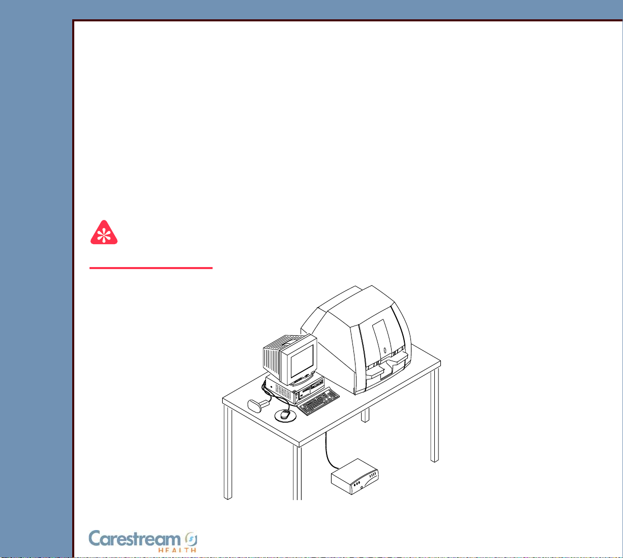
Kodak DirectView CR 500 SYSTEM
Service Code: 4366
Important
Qualified service personnel must repair this equipment.
Publication No. DG4366-1
09OCT07
Supersedes DG4366-1
22NOV04
H195_0016BC
© CARESTREAM HEALTH, INC.
Page 2

DIAGNOSTICS
09OCT07
DG4366-1
Page
2 of 211
PLEASE NOTE The information contained herein is based on the experience and knowledge relating to t he subject
matter gained by Carestream Health, Inc. prior to publication.
No patent license is granted by this information.
Carestream Health, Inc. reserves the right to chang e this information withou t notice, and ma kes no
warranty, express or implied, with respect to this infor mation. Carestr eam Health shall not be liable
for any loss or damage, including consequ ential o r special damages, resulting fr om any use of this
information, even if loss or damage is caused by Carestream Health’s negligence or other fault.
This equipment includes parts and assemblies sensitive to damage from electrostatic
discharge. Use caution to prevent damage during all service procedures.
Table of Contents
Description Page
Using the Diagnostics . . . . . . . . . . . . . . . . . . . . . . . . . . . . . . . . . . . . . . . . . . . . . . . . . . 12
“System Service Diagnostic” Screen. . . . . . . . . . . . . . . . . . . . . . . . . . . . . . . . . . 12
Functions of the “System Service Diagnostic” Screen . . . . . . . . . . . . . . . . . . . 20
Diagnostic Tests . . . . . . . . . . . . . . . . . . . . . . . . . . . . . . . . . . . . . . . . . . . . . . . . . . . 33
Individual Component Control. . . . . . . . . . . . . . . . . . . . . . . . . . . . . . . . . . . . 33
Component Control: Step . . . . . . . . . . . . . . . . . . . . . . . . . . . . . . . . . . . . . . . 36
Light Test. . . . . . . . . . . . . . . . . . . . . . . . . . . . . . . . . . . . . . . . . . . . . . . . . . . . . 41
Slow Scan Current and Velocity Tests. . . . . . . . . . . . . . . . . . . . . . . . . . . . . 45
Laser Power . . . . . . . . . . . . . . . . . . . . . . . . . . . . . . . . . . . . . . . . . . . . . . . . . . . 48
GALVO Test. . . . . . . . . . . . . . . . . . . . . . . . . . . . . . . . . . . . . . . . . . . . . . . . . . . 49
GALVO PLOT . . . . . . . . . . . . . . . . . . . . . . . . . . . . . . . . . . . . . . . . . . . . . . . . . . 53
Transport . . . . . . . . . . . . . . . . . . . . . . . . . . . . . . . . . . . . . . . . . . . . . . . . . . . . . 56
AUTOLOOPER . . . . . . . . . . . . . . . . . . . . . . . . . . . . . . . . . . . . . . . . . . . . . . . . . 57
System Self Tests . . . . . . . . . . . . . . . . . . . . . . . . . . . . . . . . . . . . . . . . . . . . . . 58
Diagnostic Procedures . . . . . . . . . . . . . . . . . . . . . . . . . . . . . . . . . . . . . . . . . . . . . . 60
Checking the Error Logs . . . . . . . . . . . . . . . . . . . . . . . . . . . . . . . . . . . . . . . . 60
Checking the Error Frequency Log . . . . . . . . . . . . . . . . . . . . . . . . . . . . . . . 61
Checking the Actuation Logs . . . . . . . . . . . . . . . . . . . . . . . . . . . . . . . . . . . . 62
Storing the Error Logs on a Disk . . . . . . . . . . . . . . . . . . . . . . . . . . . . . . . . . 63
Clearing the Error Logs . . . . . . . . . . . . . . . . . . . . . . . . . . . . . . . . . . . . . . . . . 64
Displaying the Software Versions. . . . . . . . . . . . . . . . . . . . . . . . . . . . . . . . . 65
Downloading Software to the BOARDS . . . . . . . . . . . . . . . . . . . . . . . . . . . . 67
Error Codes . . . . . . . . . . . . . . . . . . . . . . . . . . . . . . . . . . . . . . . . . . . . . . . . . . . . . . . . . . . 68
Overview. . . . . . . . . . . . . . . . . . . . . . . . . . . . . . . . . . . . . . . . . . . . . . . . . . . . . . . . . . 68
CASSETTE LOAD . . . . . . . . . . . . . . . . . . . . . . . . . . . . . . . . . . . . . . . . . . . . . . . . . . 70
Page 3

DIAGNOSTICS
09OCT07
DG4366-1
Page
3 of 211
940 - Display only, no Log Message. . . . . . . . . . . . . . . . . . . . . . . . . . . . . . . 70
941 - Display only, no Log Message. . . . . . . . . . . . . . . . . . . . . . . . . . . . . . . 70
942 - Display only, no Log Message. . . . . . . . . . . . . . . . . . . . . . . . . . . . . . . 70
950 - Display only, no Log Message. . . . . . . . . . . . . . . . . . . . . . . . . . . . . . . 70
951 - Display only, no Log Message. . . . . . . . . . . . . . . . . . . . . . . . . . . . . . . 71
952 - Display only, no Log Message. . . . . . . . . . . . . . . . . . . . . . . . . . . . . . . 71
953 - Display only, no Log Message. . . . . . . . . . . . . . . . . . . . . . . . . . . . . . . 71
954 - Display only, no Log Message. . . . . . . . . . . . . . . . . . . . . . . . . . . . . . . 72
955 - Display only, no Log Message. . . . . . . . . . . . . . . . . . . . . . . . . . . . . . . 72
956 - Display only, no Log Message. . . . . . . . . . . . . . . . . . . . . . . . . . . . . . . 72
957 - Display only, no Log Message. . . . . . . . . . . . . . . . . . . . . . . . . . . . . . . 73
958 - Display only, no Log Message. . . . . . . . . . . . . . . . . . . . . . . . . . . . . . . 73
959 - Display only, no Log Message. . . . . . . . . . . . . . . . . . . . . . . . . . . . . . . 73
960 - Display only, no Log Message. . . . . . . . . . . . . . . . . . . . . . . . . . . . . . . 73
961 - Display only, no Log Message. . . . . . . . . . . . . . . . . . . . . . . . . . . . . . . 74
962 - Display only, no Log Message. . . . . . . . . . . . . . . . . . . . . . . . . . . . . . . 74
963 - Display only, no Log Message. . . . . . . . . . . . . . . . . . . . . . . . . . . . . . . 74
994 - Display only, no Log Message. . . . . . . . . . . . . . . . . . . . . . . . . . . . . . . 75
995 - Display only, no Log Message. . . . . . . . . . . . . . . . . . . . . . . . . . . . . . . 75
996 - Display only, no Log Message. . . . . . . . . . . . . . . . . . . . . . . . . . . . . . . 75
997 - Display only, no Log Message. . . . . . . . . . . . . . . . . . . . . . . . . . . . . . . 75
998 - Display only, no Log Message. . . . . . . . . . . . . . . . . . . . . . . . . . . . . . . 76
999 - Display only, no Log Message. . . . . . . . . . . . . . . . . . . . . . . . . . . . . . . 76
1000 - Display only, no Log Message. . . . . . . . . . . . . . . . . . . . . . . . . . . . . . 76
1001 - Display only, no Log Message. . . . . . . . . . . . . . . . . . . . . . . . . . . . . . 76
10021 - MSC BOARD A1: Software malfunction . . . . . . . . . . . . . . . . . . . . . 76
10022 - MSC BOARD A1: Software malfunction . . . . . . . . . . . . . . . . . . . . . 77
10024 - MSC BOARD A1: Software malfunction . . . . . . . . . . . . . . . . . . . . . 77
10030 - READER did not read the CASSETTE BAR CODE . . . . . . . . . . . . 78
10031 - Cannot home cassette guides. . . . . . . . . . . . . . . . . . . . . . . . . . . . . 78
10032 - Cannot activate cassette load switch. . . . . . . . . . . . . . . . . . . . . . . 79
10033 - Cannot clamp the cassette correctly . . . . . . . . . . . . . . . . . . . . . . . 79
10034 - Unable to retract cassette feed pin . . . . . . . . . . . . . . . . . . . . . . . . . 79
10035 - Cannot home the feed motor. . . . . . . . . . . . . . . . . . . . . . . . . . . . . . 79
10036 - Display only, no Log Message. . . . . . . . . . . . . . . . . . . . . . . . . . . . . 80
10037 - Retrying clamp cassette with guides . . . . . . . . . . . . . . . . . . . . . . . 80
10038 - Retrying extract screen from cassette . . . . . . . . . . . . . . . . . . . . . . 80
10039 - BAR CODE read failure occurred . . . . . . . . . . . . . . . . . . . . . . . . . . 81
10040 - MSC BOARD A1: Software malfunction - RTXC timer
allocation failure . . . . . . . . . . . . . . . . . . . . . . . . . . . . . . . . . . . . . . . . . . . . . 81
10999 - MSC BOARD A1: Software malfunction . . . . . . . . . . . . . . . . . . . . . 82
CASSETTE . . . . . . . . . . . . . . . . . . . . . . . . . . . . . . . . . . . . . . . . . . . . . . . . . . . . . . . . 82
Page 4

DIAGNOSTICS
09OCT07
DG4366-1
Page
4 of 211
Screen Return . . . . . . . . . . . . . . . . . . . . . . . . . . . . . . . . . . . . . . . . . . . . . . . . . 82
SLOW SCAN AY . . . . . . . . . . . . . . . . . . . . . . . . . . . . . . . . . . . . . . . . . . . . . . . . . . . 83
12009 - Caution! SLOW SCAN MOTOR drawing too much power . . . . . . 83
12012 - SLOW SCAN AY: Timeout Error . . . . . . . . . . . . . . . . . . . . . . . . . . . 83
12013 - SLOW SCAN AY: Timeout error . . . . . . . . . . . . . . . . . . . . . . . . . . . 83
12014 - MSC BOARD A1: Software Error for SLOW SCAN . . . . . . . . . . . . 83
12100 - SLOW SCAN CONTROLLER BOARD A6: Software Error . . . . . . 84
12101 - SLOW SCAN frequency locked range error while scanning . . . . 84
12102 - SLOW SCAN stopped, position error while scanning . . . . . . . . . 85
12103 - SLOW SCAN stopped, frequency lock motion stalled error
while scanning. . . . . . . . . . . . . . . . . . . . . . . . . . . . . . . . . . . . . . . . . . . . . . . 85
12107 - SLOW SCAN: +24 V DC malfunction during scan. . . . . . . . . . . . . 86
12108 - SLOW SCAN stopped during scan . . . . . . . . . . . . . . . . . . . . . . . . . 86
12109 - SLOW SCAN stopped during scan . . . . . . . . . . . . . . . . . . . . . . . . . 87
12110 - SLOW SCAN did not communicate with the
MOTION SYSTEM CONTROL . . . . . . . . . . . . . . . . . . . . . . . . . . . . . . . . . . . 87
12111 - SLOW SCAN did not move. . . . . . . . . . . . . . . . . . . . . . . . . . . . . . . . 87
12112 - SLOW SCAN did not move. . . . . . . . . . . . . . . . . . . . . . . . . . . . . . . . 87
12113 - SLOW SCAN CONTROLLER BOARD A6: NVRAM malfunctioned 87
12115 - SLOW SCAN CONTROLLER BOARD A6: Software Error . . . . . . 88
12116 - SLOW SCAN CONTROLLER BOARD A6 did not communicate
with MSC . . . . . . . . . . . . . . . . . . . . . . . . . . . . . . . . . . . . . . . . . . . . . . . . . . . 88
12120 - SLOW SCAN did not move. . . . . . . . . . . . . . . . . . . . . . . . . . . . . . . . 88
12121 - SLOW SCAN did not move. . . . . . . . . . . . . . . . . . . . . . . . . . . . . . . . 88
12122 - SLOW SCAN COIL BOARD A7 malfunctioned. . . . . . . . . . . . . . . . 89
12123 - SLOW SCAN CONTROLLER BOARD A6: Software Error . . . . . . 89
12124 - SLOW SCAN CONTROLLER BOARD A6: Software Error . . . . . . 89
12125 - SLOW SCAN COIL BOARD A7 malfunctioned. . . . . . . . . . . . . . . . 89
12126 - Caution! SLOW SCAN MOTOR is overheated . . . . . . . . . . . . . . . . 89
12130 - SLOW SCAN CONTROLLER BOARD A6: Software Error . . . . . . 90
12131 - SLOW SCAN CONTROLLER BOARD A6 did not communicate
with MSC . . . . . . . . . . . . . . . . . . . . . . . . . . . . . . . . . . . . . . . . . . . . . . . . . . . 90
12132 - SLOW SCAN CONTROLLER BOARD A6 did not communicate
with MSC . . . . . . . . . . . . . . . . . . . . . . . . . . . . . . . . . . . . . . . . . . . . . . . . . . . 90
12201 - SLOW SCAN CONTROLLER BOARD A6: Programming Error . . 90
12202 to 12260 - SLOW SCAN CONTROLLER BOARD A6: “Memory
Command” Error. . . . . . . . . . . . . . . . . . . . . . . . . . . . . . . . . . . . . . . . . . . . . 91
12261 - Roller Pair 1 Cam Motor Timeout . . . . . . . . . . . . . . . . . . . . . . . . . . 93
12262 - Roller Pair 2 Cam Motor Timeout . . . . . . . . . . . . . . . . . . . . . . . . . . 95
12263 - Roller Pair 3 Cam Motor Timeout . . . . . . . . . . . . . . . . . . . . . . . . . . 97
12264 - Screen start sensor blocked . . . . . . . . . . . . . . . . . . . . . . . . . . . . . . 98
12265 - Screen start timeout. Screen did not enter reader . . . . . . . . . . . . 99
Page 5

DIAGNOSTICS
09OCT07
DG4366-1
Page
5 of 211
12266 - Screen did not fully enter the erase assembly . . . . . . . . . . . . . . . 102
12267 - Screen did not return to cassette . . . . . . . . . . . . . . . . . . . . . . . . . . 103
12301 - Slow Scan frequency locked range error while not scanning. . . 103
12302 - SLOW SCAN stopped, position error while not scanning. . . . . . 104
12303 - SLOW SCAN stopped, frequency lock motion stalled error
while not scanning . . . . . . . . . . . . . . . . . . . . . . . . . . . . . . . . . . . . . . . . . . . 106
12307 - SLOW SCAN: +24 V DC malfunction during SCREEN transport. 107
12896 - SLOW SCAN CONTROLLER BOARD A6: Unexpected Reset . . . 107
12900 - SLOW SCAN CONTROLLER BOARD A6: Unexpected Retry . . . . 107
12901 - SLOW SCAN CONTROLLER BOARD A6: Unexpected Retry . . . . 107
12902 - SLOW SCAN CONTROLLER BOARD A6: Unexpected Retry . . . . 108
12903 - SLOW SCAN CONTROLLER BOARD A6: Unexpected Retry . . . . 108
12904 - SLOW SCAN CONTROLLER BOARD A6: Unexpected Retry . . . . 109
12905 - SLOW SCAN CONTROLLER BOARD A6: Unexpected Retry . . . . 109
12906 - SLOW SCAN CONTROLLER BOARD A6: Unexpected Retry . . . . 109
12907 - SLOW SCAN CONTROLLER BOARD A6: Unexpected Retry . . . . 109
12908 - SLOW SCAN CONTROLLER BOARD A6: Unexpected Retry . . . . 110
12909 - SLOW SCAN CONTROLLER BOARD A6: Unexpected Retry . . . . 110
12910 - SLOW SCAN CONTROLLER BOARD A6: Unexpected Retry . . . . 110
12911 - SLOW SCAN CONTROLLER BOARD A6: Unexpected Retry . . . . 110
12913 - SLOW SCAN CONTROLLER BOARD A6: Unexpected Retry . . . . 110
12914 - SLOW SCAN CONTROLLER BOARD A6: Unexpected Retry . . . . 111
12915 - SLOW SCAN CONTROLLER BOARD A6: Unexpected Retry . . . . 111
12930 - SLOW SCAN: Unexpected Retry during Current Test . . . . . . . . . 111
12931 - SLOW SCAN: Unexpected Retry during Velocity Test. . . . . . . . . 112
12941 - SLOW SCAN: Unexpected Retry during Communication to
MSC. . . . . . . . . . . . . . . . . . . . . . . . . . . . . . . . . . . . . . . . . . . . . . . . . . . . . . . . 112
ERASE LAMPS . . . . . . . . . . . . . . . . . . . . . . . . . . . . . . . . . . . . . . . . . . . . . . . . . . . . 112
13009 - All ERASE LAMPS malfunctioned . . . . . . . . . . . . . . . . . . . . . . . . . . 112
13010 - Erase time exceeds maximum allowed. . . . . . . . . . . . . . . . . . . . . . 114
13011 - Command to Erase did not occur . . . . . . . . . . . . . . . . . . . . . . . . . . 114
13012 - MSC BOARD A1: Invalid Command for ERASE LAMPS . . . . . . . 114
13013 - MSC BOARD A1: Software failure during erase . . . . . . . . . . . . . . 114
13899 - General Erase Error.. . . . . . . . . . . . . . . . . . . . . . . . . . . . . . . . . . . . . 114
POWER SUPPLY . . . . . . . . . . . . . . . . . . . . . . . . . . . . . . . . . . . . . . . . . . . . . . . . . . . 115
14001 - SLOW SCAN: Malfunction of 24 V Power . . . . . . . . . . . . . . . . . . . 115
14002 - STEPPER: Malfunction of 24 V Power . . . . . . . . . . . . . . . . . . . . . . 115
14008 - SLOW SCAN: Initialization Error. . . . . . . . . . . . . . . . . . . . . . . . . . . 115
14010 - Slow Scan Async Reset Error . . . . . . . . . . . . . . . . . . . . . . . . . . . . . 115
14015 - MSC initialization failed . . . . . . . . . . . . . . . . . . . . . . . . . . . . . . . . . . 115
14016 - MSC initialization succeeded . . . . . . . . . . . . . . . . . . . . . . . . . . . . . . 115
14017 - MSC initialization started
. . . . . . . . . . . . . . . . . . . . . . . . . . . . . . . . . 116
Page 6

DIAGNOSTICS
09OCT07
DG4366-1
Page
6 of 211
14018 - Display only, no Log Message. . . . . . . . . . . . . . . . . . . . . . . . . . . . . 116
14019 - The MSC BOARD A1 has reported a model number that is
not consistent with the current version of embedded MCPU software 116
14020 - SCREEN eject failed. The SCREEN may or may not still be
inside of the machine . . . . . . . . . . . . . . . . . . . . . . . . . . . . . . . . . . . . . . . . . 117
DATA PATH . . . . . . . . . . . . . . . . . . . . . . . . . . . . . . . . . . . . . . . . . . . . . . . . . . . . . . 117
15001 - MCPU BOARD A2: Fatal Error in Software . . . . . . . . . . . . . . . . . . 117
15002 - MCPU BOARD A2: Fatal Error in Software . . . . . . . . . . . . . . . . . . 117
15003 - MCPU BOARD A2: Communications Error in Software . . . . . . . . 118
15005 - LASER: Reference Error. . . . . . . . . . . . . . . . . . . . . . . . . . . . . . . . . . 118
15006 - Communications Error between MCPU BD A2 and
GALVO BD A4 . . . . . . . . . . . . . . . . . . . . . . . . . . . . . . . . . . . . . . . . . . . . . . 118
15007 - Communications Error between MCPU BD A2 and
GALVO BD A4 . . . . . . . . . . . . . . . . . . . . . . . . . . . . . . . . . . . . . . . . . . . . . . . 119
15008 - Start of Scan Timeout . . . . . . . . . . . . . . . . . . . . . . . . . . . . . . . . . . . . 119
15011 - LASER: Power is below the lower limit . . . . . . . . . . . . . . . . . . . . . 120
15012 - Communications Error between MCPU BOARD A2 and the PC . 120
15013 - Image Quality Warning . . . . . . . . . . . . . . . . . . . . . . . . . . . . . . . . . . . 120
15014 - LASER power not calibrated . . . . . . . . . . . . . . . . . . . . . . . . . . . . . . 121
15015 - SCREEN not calibrated. . . . . . . . . . . . . . . . . . . . . . . . . . . . . . . . . . . 121
15016 - The LASER reference voltage is too high . . . . . . . . . . . . . . . . . . . 121
15017 - SCREEN not calibrated. . . . . . . . . . . . . . . . . . . . . . . . . . . . . . . . . . . 122
15018 - There was an error reading or writing to the PCMCIA card.. . . . 122
15040 - Communications Error Between MCPU and the PC . . . . . . . . . . . 122
15800 - Image resent at NT reboot . . . . . . . . . . . . . . . . . . . . . . . . . . . . . . . . 123
15900 - NT rejected image at end of scan. Retransmission being
attempted . . . . . . . . . . . . . . . . . . . . . . . . . . . . . . . . . . . . . . . . . . . . . . . . . . . 123
Calibration . . . . . . . . . . . . . . . . . . . . . . . . . . . . . . . . . . . . . . . . . . . . . . . . . . . . . . . . 124
16001 - Calibration Error: Did not find START OF SCAN position . . . . . . 124
16002 - Calibration Error: Did not find Offset . . . . . . . . . . . . . . . . . . . . . . . 124
16003 - Calibration Error: Did not find Amplitude . . . . . . . . . . . . . . . . . . . 125
16005 - Calibration Error: Routine did not receive image in the
time allowed . . . . . . . . . . . . . . . . . . . . . . . . . . . . . . . . . . . . . . . . . . . . . . . . . 125
16006 - Calibration Error: Did not acquire image . . . . . . . . . . . . . . . . . . . . 125
16010 - Possible Light Leak. . . . . . . . . . . . . . . . . . . . . . . . . . . . . . . . . . . . . . 126
16011 - Imaging System Error occurred during Initialization . . . . . . . . . . 126
16012 - PMT/DAS BOARD A5: Calculation Error occurred during
Initialization . . . . . . . . . . . . . . . . . . . . . . . . . . . . . . . . . . . . . . . . . . . . . . . . . . . 126
16013 - Imaging System contains out-of-range noise . . . . . . . . . . . . . . . . 127
16014 - Imaging System did not zero or PMT did not calibrate . . . . . . . . 127
16016 - Malfunctioning PMT . . . . . . . . . . . . . . . . . . . . . . . . . . . . . . . . . . . . . 127
Page 7

DIAGNOSTICS
09OCT07
DG4366-1
Page
7 of 211
16019 - Calibration could not find offset, rotate GALVO
counterclockwise . . . . . . . . . . . . . . . . . . . . . . . . . . . . . . . . . . . . . . . . . . . . 127
16020 - Calibration could not find offset, rotate GALVO clockwise . . . . . 127
16021 - Malfunctioning PMT1: Gain out of range . . . . . . . . . . . . . . . . . . . . 128
16022 - Malfunctioning PMT2: Gain out of range . . . . . . . . . . . . . . . . . . . . 128
16026 - The laser diode is not calibrated. . . . . . . . . . . . . . . . . . . . . . . . . . . 129
16027 - The laser diode calibration data is out of range . . . . . . . . . . . . . . 129
16028 - The galvo is out of range . . . . . . . . . . . . . . . . . . . . . . . . . . . . . . . . . 129
“Self Test” for the MASTER CENTRAL PROCESSING UNIT . . . . . . . . . . . . . . . 130
19001 - Check GALVO COMMUNICATIONS CABLE . . . . . . . . . . . . . . . . . . 130
19002 - Check PMT BOARD CABLE and power . . . . . . . . . . . . . . . . . . . . . 130
19003 - Check the power to the GALVO BOARD . . . . . . . . . . . . . . . . . . . . 130
19004 - GALVO AGC reference is too high. Suggest check if GALVO
connected and/or ad just AGC . . . . . . . . . . . . . . . . . . . . . . . . . . . . . . . . . . 130
19005 - Check the GALVO reference (too low) . . . . . . . . . . . . . . . . . . . . . . 131
19006 - Memory self test failed. Replace the MCPU BOARD . . . . . . . . . . 131
19009 - The LASER diode off power is too high. . . . . . . . . . . . . . . . . . . . . 131
19010 - The LASER diode on power is too low . . . . . . . . . . . . . . . . . . . . . 131
19011 - PMT BOARD ramp test failed. . . . . . . . . . . . . . . . . . . . . . . . . . . . . . 132
19012 - Galvo sweep error . . . . . . . . . . . . . . . . . . . . . . . . . . . . . . . . . . . . . . . 132
MECHANISM SYSTEM CONTROL BOARD . . . . . . . . . . . . . . . . . . . . . . . . . . . . . . 132
22000 - MSC BOARD A1: Fatal Software Error . . . . . . . . . . . . . . . . . . . . . . 132
22001 - MSC BOARD A1: Memory did not
erase during Download . . . . . 132
22002 - MSC BOARD A1: Error during download of MSC Software. . . . . 133
22003 - MSC BOARD A1: Checksum of Main Application failed . . . . . . . 133
22004 - MSC BOARD A1: RAM Test failed . . . . . . . . . . . . . . . . . . . . . . . . . . 133
22005 - MSC BOARD A1: Error during download of MSC Software. . . . . 134
22006 - MSC BOARD A1: Error during download of MSC Software. . . . . 134
22007 - MSC BOARD A1: Error during download of MSC Software. . . . . 134
22008 - MSC BOARD A1: Error during download of MSC Software. . . . . 134
22009 - MSC BOARD A1: Error during download of MSC Software. . . . . 135
22010 - MSC BOARD A1: Error during download of MSC Software. . . . . 136
22011 - MSC BOARD A1: Error during download of MSC Software. . . . . 136
MECHANISM SYSTEM CONTROL BOARD RTXC . . . . . . . . . . . . . . . . . . . . . . . . 137
29001 - 29008 - MSC BOARD A1: Software malfunctioned . . . . . . . . . . . . 137
MECHANISM SYSTEM CONTROL BOARD SYSTEM . . . . . . . . . . . . . . . . . . . . . . 138
30002 - 30033 - MSC BOARD A1: Software malfunctioned . . . . . . . . . . . . 138
30041 - Cassette task did not respond to a command . . . . . . . . . . . . . . . 138
30042 - Did not receive a Load SCREEN command . . . . . . . . . . . . . . . . . . 138
30043 - MSC is in Fatal Error state. . . . . . . . . . . . . . . . . . . . . . . . . . . . . . . . 138
30044 - General MSC Error . . . . . . . . . . . . . . . . . . . . . . . . . . . . . . . . . . . . . . 138
30045 - Interlock switch is open . . . . . . . . . . . . . . . . . . . . . . . . . . . . . . . . . . 139
Page 8

DIAGNOSTICS
09OCT07
DG4366-1
Page
8 of 211
30046 - 24 V supply error. . . . . . . . . . . . . . . . . . . . . . . . . . . . . . . . . . . . . . . . 139
30047 - Interlock switch closed . . . . . . . . . . . . . . . . . . . . . . . . . . . . . . . . . . . 139
30048 - Transient 24 V loss. . . . . . . . . . . . . . . . . . . . . . . . . . . . . . . . . . . . . . 139
Communications for the MECHANISM SYSTEM CONTROL BOARD . . . . . . . . 139
32001 - Communications malfunctioned between MCPU and
SSC BOARDS . . . . . . . . . . . . . . . . . . . . . . . . . . . . . . . . . . . . . . . . . . . . . . . 139
32002 - MSC BOARD A1: Internal Communications Error. . . . . . . . . . . . . 140
32003 - MSC BOARD A1: Internal Communications Error. . . . . . . . . . . . . 140
32004 - Communications Error between MCPU and SSC BOARDS. . . . . 140
32005 - Communications Error between MCPU and SSC BOARDS. . . . . 141
32006 - Synchronization lost. . . . . . . . . . . . . . . . . . . . . . . . . . . . . . . . . . . . . 141
SHUTDOWN MANAGER . . . . . . . . . . . . . . . . . . . . . . . . . . . . . . . . . . . . . . . . . . . . . 141
47001 - Communications to MCPU BD failed during Shut Down . . . . . . . 141
47002 - Internal communications failure . . . . . . . . . . . . . . . . . . . . . . . . . . . 141
47003 - Internal communications to UPS failed . . . . . . . . . . . . . . . . . . . . . 142
47500 - 47504 - Internal communications to UPS failed . . . . . . . . . . . . . . 142
47510 - 47511 - Internal communications failure to UPS1 . . . . . . . . . . . . . 142
47520 - 47522 - Internal communications failure to UPS1 . . . . . . . . . . . . . 142
47550 - The BATTERY in UPS1 is too low. System will be shutdown
in 1 minute. . . . . . . . . . . . . . . . . . . . . . . . . . . . . . . . . . . . . . . . . . . . . . . . . . 142
47551 - Display only, no Log Message. . . . . . . . . . . . . . . . . . . . . . . . . . . . . 143
47900 - Display only, no Log Message. . . . . . . . . . . . . . . . . . . . . . . . . . . . . 143
47950 - Display only, no Log Message. . . . . . . . . . . . . . . . . . . . . . . . . . . . . 143
47951 - Display only, no Log Message. . . . . . . . . . . . . . . . . . . . . . . . . . . . . 143
47952 - Display only, no Log Message. . . . . . . . . . . . . . . . . . . . . . . . . . . . . 144
47960 - Display only, no Log Message. . . . . . . . . . . . . . . . . . . . . . . . . . . . . 144
47961 - Display only, no Log Message. . . . . . . . . . . . . . . . . . . . . . . . . . . . . 144
47962 - Display only, no Log Message. . . . . . . . . . . . . . . . . . . . . . . . . . . . . 144
DISK MANAGER . . . . . . . . . . . . . . . . . . . . . . . . . . . . . . . . . . . . . . . . . . . . . . . . . . . 145
49000 - HARD DISK is full. DISK MANAGER not able to
remove images . . . . . . . . . . . . . . . . . . . . . . . . . . . . . . . . . . . . . . . . . . . . . . 145
49001 - Image Files have been deleted . . . . . . . . . . . . . . . . . . . . . . . . . . . . 145
Service Diagnostics . . . . . . . . . . . . . . . . . . . . . . . . . . . . . . . . . . . . . . . . . . . . . . . . 145
54001 - Entered Service Diagnostic mode . . . . . . . . . . . . . . . . . . . . . . . . . . 145
54002 - Exited Service Diagnostic mode . . . . . . . . . . . . . . . . . . . . . . . . . . . 145
54003 - Unable to enter Service Diagnostic mode . . . . . . . . . . . . . . . . . . . 145
54004 - Unable to exit Service Diagnostics . . . . . . . . . . . . . . . . . . . . . . . . . 146
54010 - MCPU application software download complete . . . . . . . . . . . . . . 146
54011 - MSC application software download complete . . . . . . . . . . . . . . . 146
54012 - Slowscan boot and app software download complete . . . . . . . . . 146
54013 - Slowscan application software download complete. . . . . . . . . . . 146
54014 - Slowscan parameters download complete. . . . . . . . . . . . . . . . . . . 147
Page 9

DIAGNOSTICS
09OCT07
DG4366-1
Page
9 of 211
54020 - Failed FTP software transfer from PC to MCPU . . . . . . . . . . . . . . 147
54021 - Failed MSC application software download. . . . . . . . . . . . . . . . . . 147
54022 - Failed SLOWSCAN boot and application software download. . . 14 8
54023 - Failed SLOWSCAN application software download . . . . . . . . . . . 148
54024 - Failed SLOWSCAN parameters download . . . . . . . . . . . . . . . . . . . 149
Installation . . . . . . . . . . . . . . . . . . . . . . . . . . . . . . . . . . . . . . . . . . . . . . . . . . . . . . . . 149
55100 - Error on the Options Diskette or this is not a valid Options
Diskette. . . . . . . . . . . . . . . . . . . . . . . . . . . . . . . . . . . . . . . . . . . . . . . . . . . . . 149
55101 - Could not open files on the Options Diskette. Try another
Options Diskette . . . . . . . . . . . . . . . . . . . . . . . . . . . . . . . . . . . . . . . . . . . . . 149
55102 - Pentium III identification not enabled on this Pentium III
class machine . . . . . . . . . . . . . . . . . . . . . . . . . . . . . . . . . . . . . . . . . . . . . . . 149
55103 - Could not open files on the Options Diskette. . . . . . . . . . . . . . . . 150
55104 - Error updating the options on the CR 500 SYSTEM. . . . . . . . . . . 150
55105 - Could not allocate essential memory . . . . . . . . . . . . . . . . . . . . . . . 150
55106 - The Options on this diskette are already enabled on this
system . . . . . . . . . . . . . . . . . . . . . . . . . . . . . . . . . . . . . . . . . . . . . . . . . . . . . 150
55107 - This Options Diskette has been used on another device . . . . . . 150
55109 - Error occurred while trying to update the Options on the
UNIT . . . . . . . . . . . . . . . . . . . . . . . . . . . . . . . . . . . . . . . . . . . . . . . . . . . . . . . 151
CD/DVD SYSTEM. . . . . . . . . . . . . . . . . . . . . . . . . . . . . . . . . . . . . . . . . . . . . . . . . . . 151
59001 - Warning: Disk Space getting low on DVD/CD-RW . . . . . . . . . . . . 151
59002 - SYSTEM - Unable to load Settings . . . . . . . . . . . . . . . . . . . . . . . . . 151
59003 - SYSTEM - Start FAILURE, Invalid command line . . . . . . . . . . . . . 151
59004 - DICOM - Unable to create Directory . . . . . . . . . . . . . . . . . . . . . . . . 151
59005 - DICOM - Incoming Store Request Rejected, Low Resource -
Import Disk Space. . . . . . . . . . . . . . . . . . . . . . . . . . . . . . . . . . . . . . . . . . . . 152
59006 - DICOM - Storing Incoming Image FAILED - Missing Image
Attributes . . . . . . . . . . . . . . . . . . . . . . . . . . . . . . . . . . . . . . . . . . . . . . . . . . . 152
59007 - DICOM - Unable to generate unique file name . . . . . . . . . . . . . . . 152
59008 - DICOM - Unable to save DicomDir File. . . . . . . . . . . . . . . . . . . . . . 152
59009 - DICOM - Unable to get Peer Name . . . . . . . . . . . . . . . . . . . . . . . . . 152
59010 - DICOM - Unable to delete File . . . . . . . . . . . . . . . . . . . . . . . . . . . . . 152
59011 - Create process failed - error = error number . . . . . . . . . . . . . . . . 153
59012 - DICOM - Copying Image to bad directory . . . . . . . . . . . . . . . . . . . 153
59013 - DICOM - Copying Image to bad directory . . . . . . . . . . . . . . . . . . . 154
59014 - DICOM - Negotiating Association FAILED - Unknown Calling
AE Title “%s” at “%s” . . . . . . . . . . . . . . . . . . . . . . . . . . . . . . . . . . . . . . . . 154
59015 - DICOM - Negotiating Association FAILED - Provider Congestion 154
59016 - DICOM - Negotiation Association FAILED. Missing
implementation UID . . . . . . . . . . . . . . . . . . . . . . . . . . . . . . . . . . . . . . . . . . . 154
Page 10

DIAGNOSTICS
09OCT07
DG4366-1
Page
10 of 211
59017 - DICOM - Negotiating Association FAILED - Missing
Application Context . . . . . . . . . . . . . . . . . . . . . . . . . . . . . . . . . . . . . . . . . . 155
59018 - DICOM - Negotiating Association FAILED - Invalid Protocol
Version . . . . . . . . . . . . . . . . . . . . . . . . . . . . . . . . . . . . . . . . . . . . . . . . . . . . 155
59019 - DICOM - Negotiating Association FAILED - Invalid Called
AE Title . . . . . . . . . . . . . . . . . . . . . . . . . . . . . . . . . . . . . . . . . . . . . . . . . . . . 155
59020 - DICOM - Negotiating Association FAILED - No Presentation
Items Given or DICOM - Negotiating Association FAILED -
No Presentation Context . . . . . . . . . . . . . . . . . . . . . . . . . . . . . . . . . . . . . . 155
59021 - DICOM - Unable to Decode File . . . . . . . . . . . . . . . . . . . . . . . . . . . 155
59022 - DICOM - Incoming Retrieve Request FAILED -
Send Association FAILED . . . . . . . . . . . . . . . . . . . . . . . . . . . . . . . . . . . . . 156
59023 - DVD-RW drive is not ready . . . . . . . . . . . . . . . . . . . . . . . . . . . . . . . 156
59024 - Error creating DICOM_DIR file . . . . . . . . . . . . . . . . . . . . . . . . . . . . . 156
59801 - Error during Create Process or waiting for the DLA
command to complete. Advise rebooting the system . . . . . . . . . . . . . . 156
59802 - S/W programmer error - invalid argument supplied to a
dvdcntrl method . . . . . . . . . . . . . . . . . . . . . . . . . . . . . . . . . . . . . . . . . . . . . 157
59803 - Format of media failed. Either the media is the wrong type
or is unusable . . . . . . . . . . . . . . . . . . . . . . . . . . . . . . . . . . . . . . . . . . . . . . . 157
59804 - Status of media failed. Either the media is the wrong type
or is unusable . . . . . . . . . . . . . . . . . . . . . . . . . . . . . . . . . . . . . . . . . . . . . . . 157
59805 - No media was detected. Either the media was not inserted,
or is the wrong type . . . . . . . . . . . . . . . . . . . . . . . . . . . . . . . . . . . . . . . . . . 157
59806 - DLA command timed out. Either the media is the wrong type
or is unusable . . . . . . . . . . . . . . . . . . . . . . . . . . . . . . . . . . . . . . . . . . . . . . . 158
59807 - DVD/CD writer is still busy. Either the media is corrupted
or a h/w problems exists . . . . . . . . . . . . . . . . . . . . . . . . . . . . . . . . . . . . . . 158
Security Audit . . . . . . . . . . . . . . . . . . . . . . . . . . . . . . . . . . . . . . . . . . . . . . . . . . . . . 158
60000 - Component verification failed for one or more files.
Would you like to startup in unsafe mode? . . . . . . . . . . . . . . . . . . . . . . 158
61001 - The Security Log database is approaching the high watermark.
When the high watermark is exceeded old entries will be deleted. . . . 159
61002 - The Security Log database has exceed the high watermark.
Old entries will be deleted to reach the low watermark . . . . . . . . . . . . . 159
Troubleshooting . . . . . . . . . . . . . . . . . . . . . . . . . . . . . . . . . . . . . . . . . . . . . . . . . . . . . . . 160
Initialization Errors . . . . . . . . . . . . . . . . . . . . . . . . . . . . . . . . . . . . . . . . . . . . . . . . . 160
“Power-On Self-Test” (POST) Errors . . . . . . . . . . . . . . . . . . . . . . . . . . . . . . 160
Software Loading Errors . . . . . . . . . . . . . . . . . . . . . . . . . . . . . . . . . . . . . . . . 161
Loading of CASSETTE Errors . . . . . . . . . . . . . . . . . . . . . . . . . . . . . . . . . . . . 162
Application Software Errors. . . . . . . . . . . . . . . . . . . . . . . . . . . . . . . . . . . . . . 162
Dark CRT or FLAT PANEL DISPLAY . . . . . . . . . . . . . . . . . . . . . . . . . . . . . . 162
Page 11

DIAGNOSTICS
09OCT07
DG4366-1
Page
11 of 211
Image Quality . . . . . . . . . . . . . . . . . . . . . . . . . . . . . . . . . . . . . . . . . . . . . . . . . . . . . . 162
Malfunctions of SCREENS and CASSETTES. . . . . . . . . . . . . . . . . . . . . . . . . . . . 163
Checkout Procedures . . . . . . . . . . . . . . . . . . . . . . . . . . . . . . . . . . . . . . . . . . . . . . . . . . . 165
BOARDS. . . . . . . . . . . . . . . . . . . . . . . . . . . . . . . . . . . . . . . . . . . . . . . . . . . . . . . . . . 165
MECHANISM SYSTEM CONTROL BOARD A1. . . . . . . . . . . . . . . . . . . . . . . 165
MASTER CENTRAL PROCESSING UNIT BOARD A2 . . . . . . . . . . . . . . . . . 166
DIGITIZER BOARD A3. . . . . . . . . . . . . . . . . . . . . . . . . . . . . . . . . . . . . . . . . . . 169
GALVO BOARD A4 . . . . . . . . . . . . . . . . . . . . . . . . . . . . . . . . . . . . . . . . . . . . . 171
PMT/DAS BOARD A5 . . . . . . . . . . . . . . . . . . . . . . . . . . . . . . . . . . . . . . . . . . . 173
SLOW SCAN CONTROLLER BOARD A6 and COIL BOARD A7 . . . . . . . . 174
LASER DRIVER BOARD A17 . . . . . . . . . . . . . . . . . . . . . . . . . . . . . . . . . . . . . 177
Power . . . . . . . . . . . . . . . . . . . . . . . . . . . . . . . . . . . . . . . . . . . . . . . . . . . . . . . . . . . . 179
POWER SUPPLY PS1 . . . . . . . . . . . . . . . . . . . . . . . . . . . . . . . . . . . . . . . . . . . 179
POWER SUPPLY PS2 . . . . . . . . . . . . . . . . . . . . . . . . . . . . . . . . . . . . . . . . . . . 180
ISOLATION TRANSFORMER T1 . . . . . . . . . . . . . . . . . . . . . . . . . . . . . . . . . . 182
UNINTERRUPTED POWER SUPPLY (UPS1) . . . . . . . . . . . . . . . . . . . . . . . . 185
System Status . . . . . . . . . . . . . . . . . . . . . . . . . . . . . . . . . . . . . . . . . . . . . . . . . . . . . 191
Test Points and LEDs. . . . . . . . . . . . . . . . . . . . . . . . . . . . . . . . . . . . . . . . . . . . . . . . . . . 194
MECHANISM SYSTEM CONTROL BOARD A1. . . . . . . . . . . . . . . . . . . . . . . 194
MASTER CENTRAL PROCESSING UNIT BOARD A2 . . . . . . . . . . . . . . . . . 197
DIGITIZER BOARD A3. . . . . . . . . . . . . . . . . . . . . . . . . . . . . . . . . . . . . . . . . . . 200
GALVO BOARD A4 . . . . . . . . . . . . . . . . . . . . . . . . . . . . . . . . . . . . . . . . . . . . . 202
PMT/DAS BOARD A5 . . . . . . . . . . . . . . . . . . . . . . . . . . . . . . . . . . . . . . . . . . . 204
LASER DRIVER BOARD A17 . . . . . . . . . . . . . . . . . . . . . . . . . . . . . . . . . . . . . 206
SLOW SCAN CONTROLLER BOARD A6 . . . . . . . . . . . . . . . . . . . . . . . . . . . 208
LASER DRIVER PRE-REGULATOR BOARD A18. . . . . . . . . . . . . . . . . . . . . 210
Page 12
09OCT07
DG4366-1
Page
12 of 211
DIAGNOSTICS Using the Diagnostics
Section 1: Using the Diagnostics
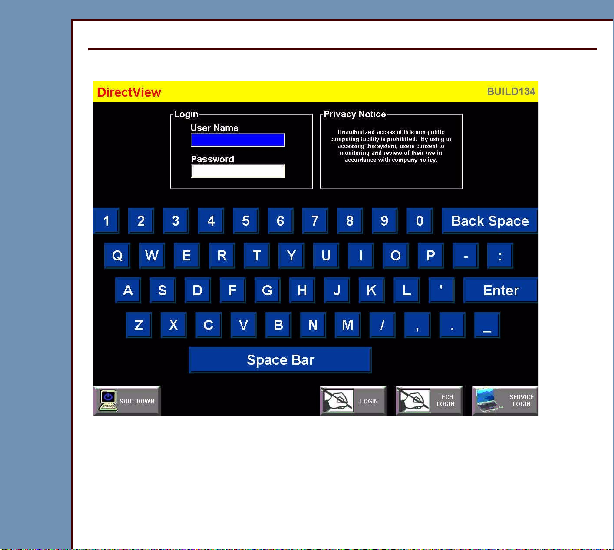
“System Service Diagnostic” Screen
1 At the “Login” screen, type the correct information for:
• “User Name”
• “Password”
Page 13
09OCT07
DG4366-1
Page
13 of 211
DIAGNOSTICS Using the Diagnostics
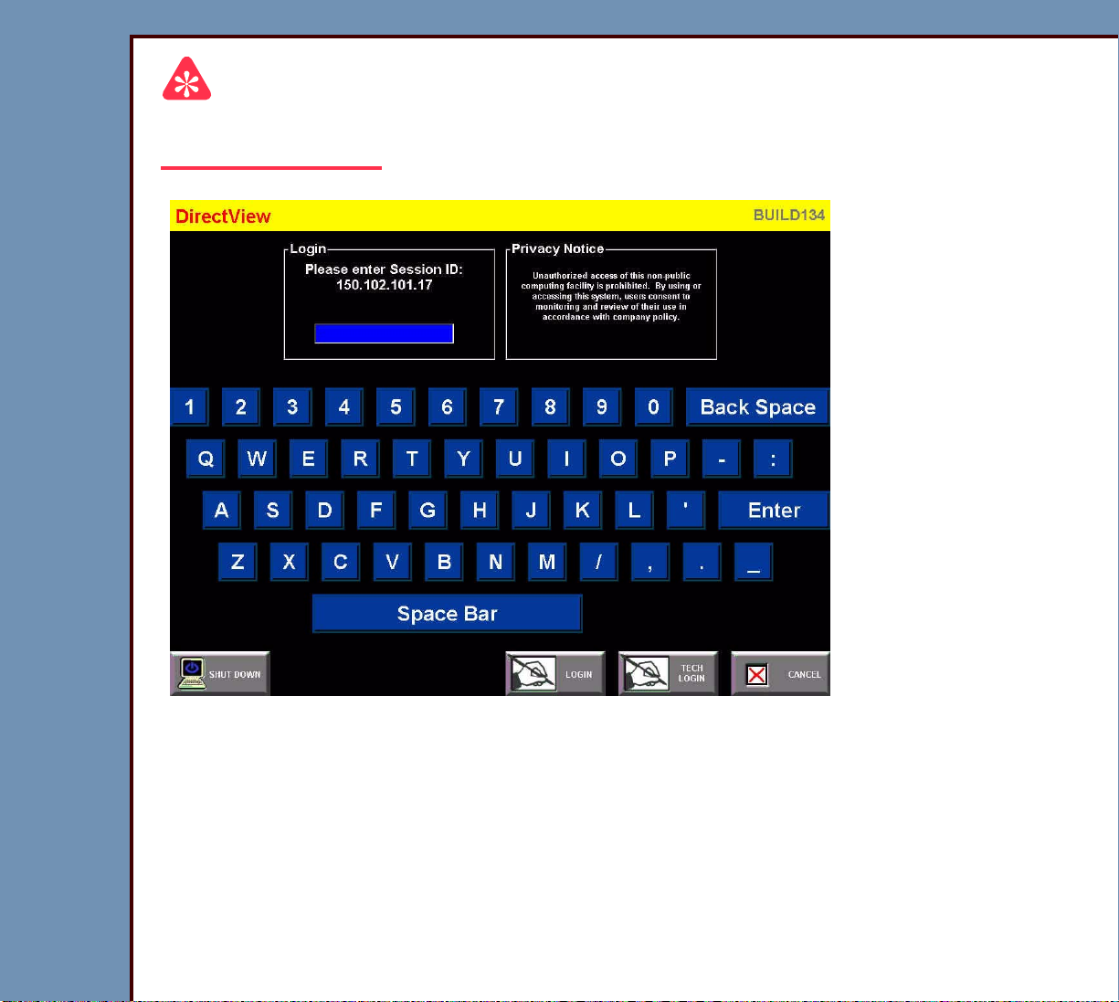
Important
For systems with Software Version ≥ 4.1, you must have a “Session ID” for access to
“Service Functions” and “Diagnostics”. See SERVICE BULLETIN 843.
2 If necessar y, at the “Service Logon” screen, type your “Session ID”.
3 At the main menu, click:
• [Service Functions]
• [Diagnostics]
Page 14
09OCT07
DG4366-1
Page
14 of 211
DIAGNOSTICS Using the Diagnostics
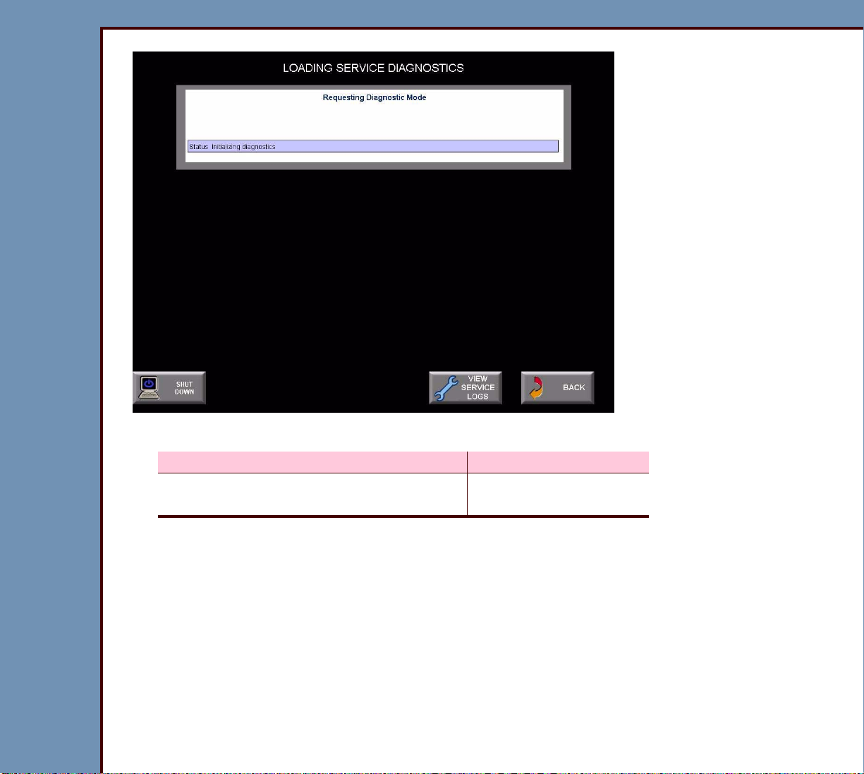
4 Does the “LOADING SERVICE DIAGNOSTICS” screen display?
Yes No
Advance to Functions of the “System
Continue with Step 5.
Service Diagnostic” Screen.
5 Check that the TX and RX LEDs are blinking on the MASTER CENTRAL PROCESSING
UNIT BOARD A2 and on the NETWORK CARD in the computer.
Page 15

09OCT07
DG4366-1
Page
15 of 211
DIAGNOSTICS Using the Diagnostics
6 Does the “CR model 0 not recognized” screen display?
Yes No
a. Check that the TX and RX LEDs are blinking on
Continue with Step 7.
the MASTER CENTRAL PROCESSING UNIT
BOARD A2 and on the NETWORK CARD in the
computer.
b. Advance to Step 9.
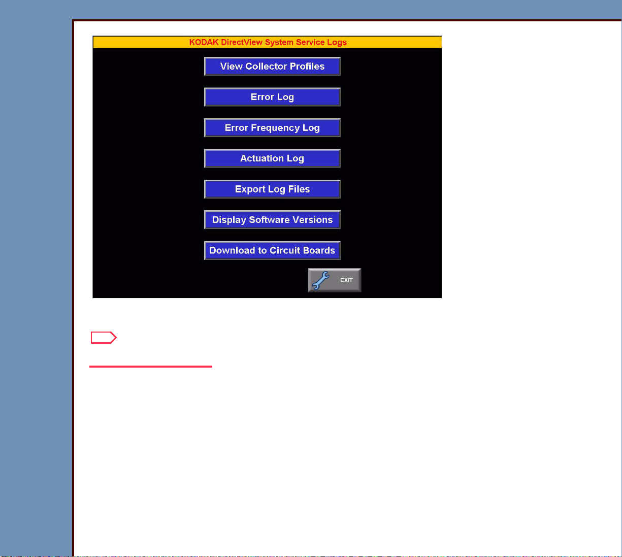
7 Select [VIEW SERVICE LOGS / SOFTWARE DOWNLOAD].
Page 16
09OCT07
DG4366-1
Page
16 of 211
DIAGNOSTICS Using the Diagnostics
8 Select [EXIT].
Note
Wait for the application to begin.
9 At the main menu, select:
• [SERVICE UTILITIES]
• [EXIT TO DESKTOP]
10 Double-click:
• “My Computer”
• “Control Panel”
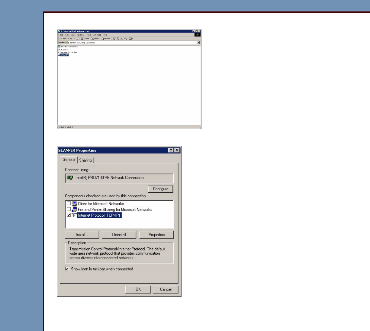
• “Network and Dial-up Connections”
Page 17
09OCT07
DG4366-1
Page
17 of 211
DIAGNOSTICS Using the Diagnostics
11 Right-click “SCANNER”.
12 Click “Properties”.
13 Double-click “Internet Protocol (TCP/IP)”.
Page 18
09OCT07
DG4366-1
Page
18 of 211
DIAGNOSTICS Using the Diagnostics
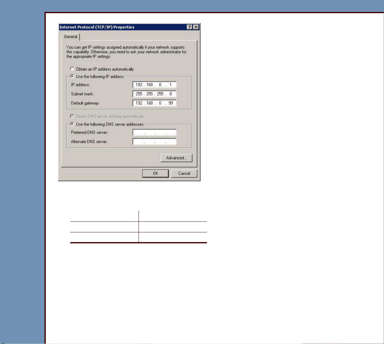
14 Click “Use the following IP address:”.
15 Check the values for the internal addresses:
“IP Address” 192.168.0.1
“Subnet Mask” 255.255.255.0
“Default Gateway” 192.168.0.99
Page 19

DIAGNOSTICS Using the Diagnostics
09OCT07
DG4366-1
Page
19 of 211
16 Are the values correct?
Yes No
a. Select:
• [OK]
• [OK]
• [Close all windows]
b. Select Start>Shutdown.
c. Wait for the CR 500 SYSTEM to de-
energize.
d. Energize the CR 500 SYSTEM.
e. At the main menu screen, click:
• [Service Functions]
• [Diagnostics]
a. Enter the correct values from Step 15.
b. Select:
• [OK]
• [OK]
• [Close]
c. Select Start>Shutdown
d. Wait for the CR 500 SYSTEM to de-
energize.
e. Energize the CR 500 SYSTEM.
f. At the main menu, select:
• [Service Functions]
• [Diagnostics]
Page 20
09OCT07
DG4366-1
Page
20 of 211
DIAGNOSTICS Using the Diagnostics
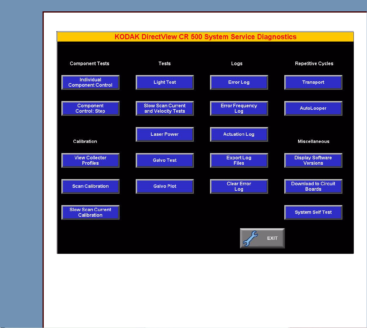
Functions of the “System Service Diagnostic” Screen
Page 21
DIAGNOSTICS Using the Diagnostics
09OCT07
DG4366-1
Page
21 of 211
Table 1 Component Tests
BUTTON Description
[Individual Component Control]
Important
For the procedure, see the Individual Component Control
test.
Allows you to actuate and check the status of:
• MOTORS, CAMS
– FEED MOTOR
– GUIDE MOTOR
– RP1 CAM
– RP2 CAM
– ERASE CAM
– SIDE ACTUATOR
– PIN EXTRACTOR
• SCANNER
– CASSETTE COMMANDS
– SLOW SCAN CONTROLLER
– ERASE MOTOR
– SCREEN START SENSOR
– ERASE LAMPS
Page 22
09OCT07
DG4366-1
Page
22 of 211
DIAGNOSTICS Using the Diagnostics
BUTTON Description
[Component Control: Step]
Important
For the procedure, see the Component Control: Step
test.
Allows you to:
• check the status of the components by executing the
following steps:
1. clamping the CASSETTE
2. removing, scanning, and erasing the SCREEN
3. returning the SCREEN to the CASSETTE
4. latching the CASSETTE
5. releasing the CASSETTE
• repair jams
• read the CASSETTE ID
Page 23
DIAGNOSTICS Using the Diagnostics
09OCT07
DG4366-1
Page
23 of 211
Table 2 Calibration
BUTTON Description
[View Collector Profiles]
Important
For the procedure, see “Setting the Calibration” in the
ADJUSTMENTS and REPLACEMENTS for the Kodak DirectView
CR 500 SYSTEM, AR4366-1.
Displays the COLLECTOR PROFILE for each size of CASSETTE:
• “OFFSET” - Number of pixels from “START” or left side of the
screen to the diagnostic image.
• “Amplitude” - Number of pixels from “OFFSET” to the last pixel
of the diagnostic image or right side of the screen.
• PMT 1 - 2: Correction value of each PMT for gain adjustment
• graphic of the values
[Scan Calibration]
Caution
• All COVERS must be installed when using this option.
• For the procedure, see “Setting the Calibration” in the
ADJUSTMENTS and REPLACEMENTS for the Kodak
DirectView CR 500 SYSTEM, AR4366-1.
• Completes the calibration of:
– GALVO AY
– PMT 1
– PMT 2
• Displays a COLLECTOR PROFILE for the 5 sizes of
STORAGE PHOSPHOR SCREENS.
• Allows calibration of the SCREENS exposed at 20 mR.
• Displays the date and time of the last successful calibration.
Page 24
09OCT07
DG4366-1
Page
24 of 211
DIAGNOSTICS Using the Diagnostics
BUTTON Description
[Slow Scan Current Calibration]
Important
For the procedure, see “Setting the Calibration” in the
ADJUSTMENTS and REPLACEMENTS for the Kodak
DirectView CR 500 SYSTEM, AR4366-1.
Completes the calibration of the SLOW SCAN AY for the
correct current at all 3 phases of the MOTOR.
Page 25
DIAGNOSTICS Using the Diagnostics
09OCT07
DG4366-1
Page
25 of 211
Ta b l e 3 Te s ts
BUTTON Description
[Light Test]
[Slow Scan Current and
Velocity Tests]
Important
For the test procedure, see Light Test.
• Checks for excessive light to the PMTs during the
loading of a CASSETTE.
• Allows you to:
– actuate or deactuate the high voltage of the PMTs
– “AUTO-ZERO” the PMTs
• Tests the signal for noise.
Caution
• An increase in current might indicate that a bind is
occurring in the SLOW SCAN AY.
• For the test procedure, see Slow Scan Current and
Velocity Tests.
• Drives the SLOW SCAN AY to the limits in both
directions.
• Displays for the SLOW SCAN AY:
– speed variation
– current
Page 26

09OCT07
DG4366-1
Page
26 of 211
DIAGNOSTICS Using the Diagnostics
BUTTON Description
[Laser Power]
Laser Warning
• Prevent direct exposure to the laser beam.
• For the test procedure, see Laser Power.
Allows you to:
• check the power of the LASER DIODE
• set the power values for a new LASER DIODE
• store the calibration values for the LASER DIODE
[Galvo Test]
Important
For the test procedure, see GALVO Test.
Allows you to:
• set the “Amplitude” of the GALVO AY
[Galvo Plot]
• check the response of the LASER DIODE
• start and stop the GALVO AY
Important
For the procedure, see the GALVO PLOT test.
Allows you to:
• check:
– response of the GALVO AY
– linearity of the GALVO AY
– automatic gain control - AGC
• set the GALVO AY without an OSCILLOSCOPE
Page 27
DIAGNOSTICS Using the Diagnostics
09OCT07
DG4366-1
Page
27 of 211
Table 4 Logs
BUTTON Description
[Error Log]
Important
For the procedure, see Checking the Error Logs.
Allows you to:
• check:
– error code and description
– date and time
– CASSETTE ID
– scan count
• collate the error codes by:
– number
– date
– CASSETTE ID
Page 28
09OCT07
DG4366-1
Page
28 of 211
DIAGNOSTICS Using the Diagnostics
BUTTON Description
[Error Frequency Log]
Important
For the procedure, see Checking the Error Frequency
Log.
Allows you to:
• check:
– frequency of each error code
– date and time of last error
• collate error codes by:
– date
– error number
– frequency
[Actuation Log]
Important
For the procedure, you must see Checking the Actuation
Logs.
Allows you to check:
• “SCAN CYCLES” - This value cannot be reset
• “BATCH ERASE CYCLES” - The number of times that
the “Batch Erase” function was used
• “TOTAL POWER-ON HOURS”
• “LASER DIODE SCAN CYCLES”
• “LASER HOURS (hours and minutes)”
• “LASER HOURS LAST CLEARED”
Page 29
09OCT07
DG4366-1
Page
29 of 211
DIAGNOSTICS Using the Diagnostics
BUTTON Description
[Export Log Files]
Important
For the procedure, see Storing the Error Logs on a Disk.
Records onto a FLOPPY DISKETTE:
• “Actuation Logs”
• error logs
• parameters of the SLOW SCAN
[Clear Error Log]
Important
For the procedure, see Clearing the Error Logs.
• Clears all the errors from the error logs.
• Displays the date when the error logs were last cleared.
Page 30
DIAGNOSTICS Using the Diagnostics
09OCT07
DG4366-1
Page
30 of 211
Table 5 “Repetitive Cycles”
BUTTON Description
[AutoLooper]
Important
• You must have:
– SLOW SCAN AY COVER installed
– LASER SAFETY COVER installed
– “Light Leak Test” enabled.
• For the procedure, see the AUTOLOOPER test.
• Errors will occur if panels are removed during the
“AutoLooper Test”.
• Automatically processes the CASSETTE to check if
it is reliable.
• Completes a test cycle including scanning and
erasing.
• Displays status screens for the SENSORS.
[Transport]
Important
• The “Light Leak Test” is disabled to allow removal of
the PANELS during the “Transport Test”.
• For the procedure, see the Transport test.
• Uses a CASSETTE to test the operation of loading.
• Displays the status of the SENSORS at each step.
Page 31
DIAGNOSTICS Using the Diagnostics
09OCT07
DG4366-1
Page
31 of 211
Table 6 Miscellaneous
BUTTON Description
[Download to Circuit
Boards]
[Display Software Versions]
Important
For the procedure, you must see Downloading Software to
the BOARDS.
Allows you to download the necessary software to all the
BOARDS from the HARD DRIVE.
Important
For the procedure, you must see Displaying the Software
Versions.
Displays the software version number for:
• CR 500 SYSTEM
• MASTER CENTRAL PROCESSING UNIT BOARD (MCPU)
A2
• MECHANISM SYSTEM CONTROL BOARD BOOT
• MECHANISM SYSTEM CONTROL BOARD A1
• SLOW SCAN CONTROLLER BOARD BOOT
• SLOW SCAN CONTROLLER BOARD FIXED APPLICATION
• SLOW SCAN CONTROLLER BOARD PRODUCT
APPLICATION
• DIGITIZER BOARD A3
• MEDICAL IMAGE MANAGER
• DIAGNOSTICS
Page 32

09OCT07
DG4366-1
Page
32 of 211
DIAGNOSTICS Using the Diagnostics
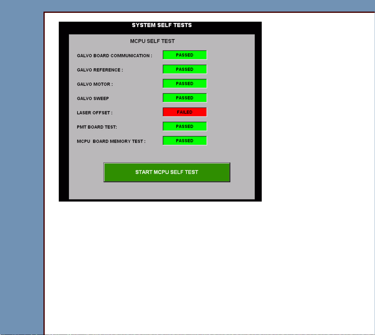
[System Self Test]
Important
For the test procedure, you must see System Self Tests.
Completes the following diagnostic tests:
• “GALVO BOARD COMMUNICATION” - Checks the
connection of the CABLE between:
– GALVO BOARD A4
– MCPU BOARD A2
• “GALVO REFERENCE” - Reads the GALVO AGC
CHANNEL connected to the reference voltage of the
GALVO.
• “GALVO MOTOR” - Reads the voltage of the GALVO
AGC to check for problems with the GALVO AY.
• “GALVO SWEEP” - Checks the functions of reading and
writing of the REGISTERS on the GALVO BOARD A4.
• “LASER OFFSET”
• “PMT BOARD TEST” - Checks the connection of the
CABLE between:
– MCPU BOARD A2
– PMT/DAS BOARD A5
• “MCPU BOARD MEMORY TEST” - Checks for errors in
the reading and writing of data to each of the image
buffers.
Page 33

09OCT07
DG4366-1
Page
33 of 211
DIAGNOSTICS Using the Diagnostics
Diagnostic Tests
Individual Component Control
1 At the “Ser vice System Diagnostic” screen, select [Individual Component Control].
Important
• If you actuate any of the components, you must select [RESET] before returning to the
diagnostics main menu.
• An “ x ” in the check box indicates a SENSOR is blocked.
• If RP1 and RP2:
– are open, an “x” is displayed in the check box
– are closed, the check box is clear
2 Select [MOTORS, CAMS] tab.
Page 34

09OCT07
DG4366-1
Page
34 of 211
DIAGNOSTICS Using the Diagnostics
3 Use the BUTTONS to actuate:
• GUIDE MOTOR
• RP 1 CAM
• RP 2 CAM
• SIDE ACTUATOR
• PIN EXTRACTION
• ERASE CAM
• FEED MOTOR
4 Select [SCANNER].
Important
You must click [LED ON] to energize the “SCREEN START SENSOR”.
Page 35

DIAGNOSTICS Using the Diagnostics
09OCT07
DG4366-1
Page
35 of 211
5 Use the BUTTONS to actuate the:
• CASSETTE COMMANDS
• SLOW SCAN CONTROLLER
• ERASE MOTOR
• SCREEN START SENSOR
• ERASE LAMPS
Important
You must select [RESET] after selecting BUTTONS.
6 Select [RESET].
Page 36
DIAGNOSTICS Using the Diagnostics
09OCT07
DG4366-1
Page
36 of 211
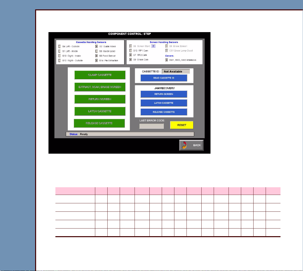
Component Control: Step
1 On the “System Ser vice Diagnostic” screen, select [Component Control: Step].
2 Inser t the CASSETTE into the CR 500 SYSTEM.
3 Check that the status of the SENSORS on the screen matches the table for the correct
size of CASSETTE.
CASSETTE S4 S1 S13 S12 S2 S3 S5 S14 S6 S15 S7 S9 S8 CS1
18 x 24 cm X X X X X - X X X - 15 x 30 cm X X X X X - X X X - 24 x 30 cm X X X X X X X - X X X - 35 x 35 cm X X X X X X X - X X X - 35 x 43 cm X X X X X X X - X X X - -
4 Select [CLAMP CASSETTE]
Page 37

DIAGNOSTICS Using the Diagnostics
09OCT07
DG4366-1
Page
37 of 211
5 Check that the status of the SENSORS on the screen matches the table.
S4 S1 S13 S12 S2 S3 S5 S14 S6 S15 S7 S9 S8 CS1
XXX X XX XX- -
6 Does the status of the SENSORS match the table?
Yes No
Continue with Step 7. 1. Check the “Status” on the screen for messages or
error codes.
2. Check the error logs. See Checking the Error Logs.
3. See the Error Codes to determine the possible cause
and action for the problem.
4. Continue with Step 7.
7 Select [EXTRACT, SCAN, ERASE SCREEN].
8 Wait approximately 10 seconds for the cycle to complete.
9 Check that the status of the SENSORS on the screen matches the table.
S4 S1 S13 S12 S2 S3 S5 S14 S6 S15 S7 S9 S8 CS1
XXXXXX-X X
10 Does the status of the SENSORS match?
Yes No
Continue with Step 11. 1. Check the “Status” on the screen for messages or
error codes.
2. Check the error logs. See Checking the Error Logs.
3. See the Error Codes to determine the possible cause
and action for the problem.
4. Continue with Step 11.
11 Select [RETURN SCREEN].
12 Wait approximately 5 seconds for the SCREEN to be inserted into the CASSETTE.
Page 38

09OCT07
DG4366-1
Page
38 of 211
DIAGNOSTICS Using the Diagnostics
Important
The S6 SCREEN START SENSOR displays a HEXIDECIMAL VALUE of:
• 00 - 60 when a screen is blocking the sensor
• C0 - FF when a screen is not blocking the sensor
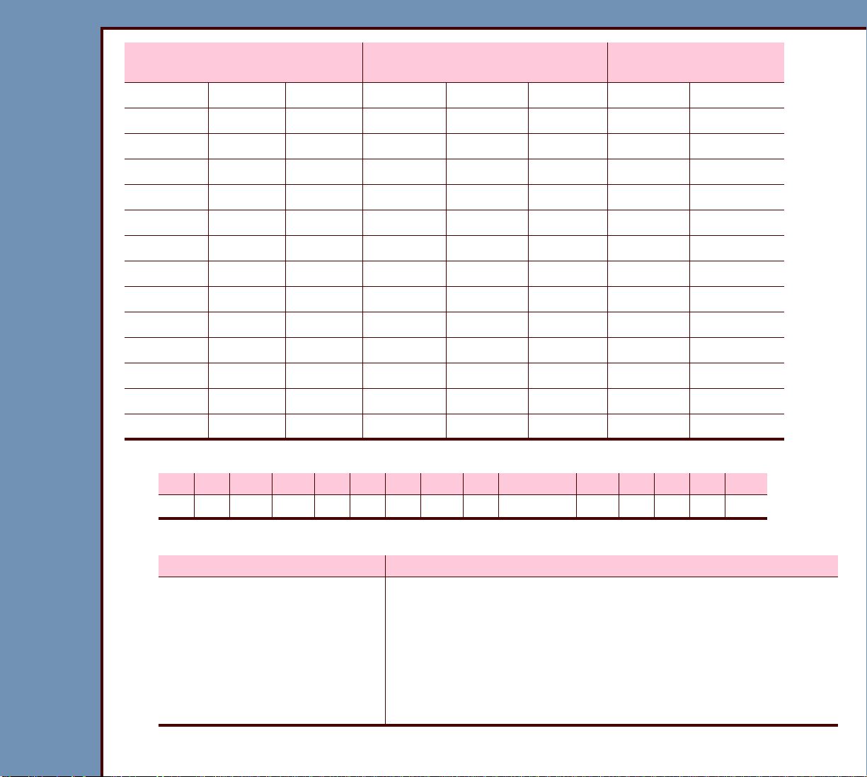
13 The following table lists the HEXIDECIMAL VALUE for the S6 SENSOR.
0 - 5F = A SCREEN is under the
S6 SENSOR
60 - BF = S6 is in a Transitional
State
CO - FF = No SCREEN
under the S6 SENSOR
020406080A0C0E0
121416181A1C1E1
222426282A2C2E2
323436383A3C3E3
424446484A4C4E4
525456585A5C5E5
626466686A6C6E6
727476787A7C7E7
828486888A8C8E8
929496989A9C9E9
0A 2A 4A 6A 8A AA CA EA
0B 2B 4B 6B 8B AB CB EB
0C 2C 4C 6C 8C AC CC EC
0D 2D 4D 6D 8D AD CD ED
0E 2E 4E 6E 8E AE CE EE
0F 2F 4F 6F 8F AF CF EF
10 30 50 70 90 B0 D0 F0
11 31 51 71 91 B1 D1 F1
12 32 52 72 92 B2 D2 F2
Page 39
09OCT07
DG4366-1
Page
39 of 211
DIAGNOSTICS Using the Diagnostics
0 - 5F = A SCREEN is under the
S6 SENSOR
60 - BF = S6 is in a Transitional
State
CO - FF = No SCREEN
under the S6 SENSOR
13 33 53 73 93 B3 D3 F3
14 34 54 74 94 B4 D4 F4
15 35 55 75 95 B5 D5 F5
16 36 56 76 96 B6 D6 F6
17 37 57 77 97 B7 D7 F7
18 38 58 78 98 B8 D8 F8
19 39 59 79 99 B9 D9 F9
1A 3A 5A 7A 9A BA DA FA
1B 3B 5B 7B 9B BB DB FB
1C 3C 5C 7C 9C BC DC FC
1D 3D 5D 7D 9D BD DD FD
1E 3E 5E 7E 9E BE DE FE
1F 3F 5F 7F 9F BF DF FF
020406080A0C0E0
14 Check that the status of the SENSORS on the screen matches the table.
S4 S1 S13 S12 S2 S3 S5 S14 S6 S6 S15 S7 S9 S8 CS1
X X X X __ X __ X __ C0 - FF __ __ __ -- --
15 Does the status of the SENSORS match?
Yes No
Continue with Step 16. 1. Check the “Status” on the screen for messages or
error codes.
2. Check the error logs. See Checking the Error Logs.
3. See the Error Codes to determine the possible cause
and action for the problem.
4. Continue with Step 16.
16 Select [LATCH CASSETTE].
Page 40

DIAGNOSTICS Using the Diagnostics
09OCT07
DG4366-1
Page
40 of 211
17 Check that the status of the SENSORS on the screen matches the table.
S4 S1 S13 S12 S2 S3 S5 S14 S6 S6 S15 S7 S9 S8 CS1
XXXXX__XX-- FFXXX----
18 Does the status of the SENSORS match?
Yes No
Continue with Step 19. 1. Check the “Status” on the screen for messages or
error codes.
2. Check the error logs. See Checking the Error Logs.
3. See the Error Codes to determine the possible cause
and action for the problem.
4. Continue with Step 19.
19 Select [RELEASE CASSETTE].
20 Check that the status of the SENSORS on the screen matches the table.
S4 S1 S13 S12 S2 S3 S5 S14 S6 S6 S15 S7 S9 S8 CS1
XXXXX__XX-- FFXXX----
21 Does the status of the SENSORS match?
Yes No
Continue with Step 22. 1. Check the “Status” on the screen for messages or
error codes.
2. Check the error logs. See Checking the Error Logs.
3. See the Error Codes to determine the possible cause
and action for the problem.
4. Continue with Step 22.
22 Remove the CASSETTE.
Page 41

DIAGNOSTICS Using the Diagnostics
09OCT07
DG4366-1
Page
41 of 211
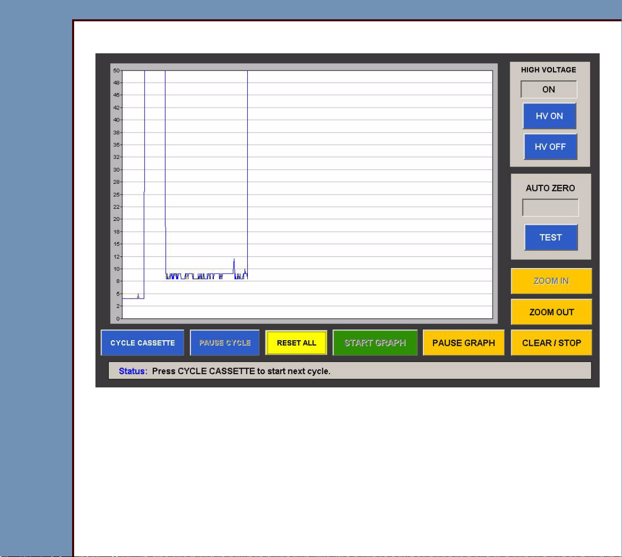
Light Test
1 On the “System Ser vice Diagnostic” screen, select [Light Test].
2 Select:
• [HV OFF]
• [TEST]
3 Wait for the test to complete.
4 Check that “PASS” displays in the “AUTO-ZERO” field.
5 Select [START GRAPH].
Page 42
09OCT07
DG4366-1
Page
42 of 211
DIAGNOSTICS Using the Diagnostics
6 Check that the value is between 4 and 5.
7 Select [HV ON].
8 The graphic displays a large “spike”.
9 Inser t a CASSETTE into the CR 500 SYSTEM.
10 Select [CYCLE CASSETTE].
Page 43

09OCT07
DG4366-1
Page
43 of 211
DIAGNOSTICS Using the Diagnostics
11 Check that the value is between 7 and 8.
12 Select [ZOOM IN].
13 When the CASSETTE is in cycle, select [HV ON].
Page 44

09OCT07
DG4366-1
Page
44 of 211
DIAGNOSTICS Using the Diagnostics
14 Check that the value:
• increases to approximately 50 - 51
• decreases to <10
15 If the value does not decrease to <10:
a. check the TAPE on the CASSETTE INTERFACE AY
b. check the COVERS and PANELS
c. do the checkout for the PMT/DAS BOARD A5
d. scan an ERASED PLATE
16 Select [CLEAR / STOP].
17 Remove the CASSETTE.
Page 45

DIAGNOSTICS Using the Diagnostics
09OCT07
DG4366-1
Page
45 of 211
Slow Scan Current and Velocity Tests
1 On the “System Ser vice Diagnostic” screen, select [Slow Scan Current and Velocity
Tests].
2 Inser t a CASSETTE into the CR 500 SYSTEM.
3 Select [Star t CURRENT TEST].
4 Wait for the test to complete.
Page 46

09OCT07
DG4366-1
Page
46 of 211
DIAGNOSTICS Using the Diagnostics
5 Check that the results are below 300.
6 If the results are not correct, check the error logs. See Checking the Error Logs.
7 Select [Star t VELOCITY TEST].
8 Wait for the test to complete.
Page 47

09OCT07
DG4366-1
Page
47 of 211
DIAGNOSTICS Using the Diagnostics
9 Check that the results are below 210.
10 If the results are not correct, check the error logs. See Checking the Error Logs.
11 Remove the CASSETTE.
Page 48
DIAGNOSTICS Using the Diagnostics
09OCT07
DG4366-1
Page
48 of 211
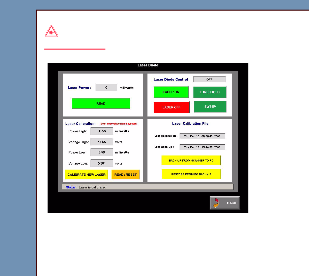
Laser Power
Laser Warning
Prevent direct exposure to the laser beam.
1 On the “System Ser vice Diagnostic” screen, select [Laser Power].
2 Select:
• [LASER ON]
• [READ]
3 Check that the “Laser Power” is 28 - 32 mW.
Page 49

DIAGNOSTICS Using the Diagnostics
09OCT07
DG4366-1
Page
49 of 211
4 Is the “Laser Power” value correct?
Yes No
Continue with the next test. 1. Check the connections to the
LASER DRIVER BOARD A17.
2. Install a new LASER DRIVER
BOARD.
5 Select [LASER OFF].
GALVO Test
1 On the “System Ser vice Diagnostic” screen, select [Galvo Test].
Laser Warning
Prevent direct exposure to the laser beam.
2 Select:
• [START GALVO]
• [LASER ON]
Page 50

09OCT07
DG4366-1
Page
50 of 211
DIAGNOSTICS Using the Diagnostics
3 Remove the PANELS.
FOLD MIRROR
laser beam
4 Inser t one sheet of paper into the CR
500 SYSTEM between:
• FOLD MIRROR
paper
• COLLECTOR
5 Obser ve the laser beam on the sheet of
paper.
CR 500 SYSTEM
COLLECTOR
H195_0051GCA
H195_0051GC
Page 51

09OCT07
DG4366-1
Page
51 of 211
DIAGNOSTICS Using the Diagnostics
6 Select [-100] or [+100] until:
• “Set Offset” value is 700
• “Set Amplitude” value is 1000
7 Obser ve the laser beam on the sheet of paper.
8 Select [+100] until the “Set Amplitude” value is 3000.
9 Obser ve the laser beam on the sheet of paper.
“Set Amplitude” Laser Beam
400 short
3900 long
Page 52

DIAGNOSTICS Using the Diagnostics
09OCT07
DG4366-1
Page
52 of 211
10 If the laser beam does not change size correctly, do the action in the table:
Description Action
The laser does not scan. The beam
illuminates in a point.
Check:
1. POWER SUPPLY PS1
2. POWER SUPPLY PS2
3. connections between:
• GALVO AY
• GALVO BOARD A4
4. GALVO AY
5. GALVO BOARD A4
The laser beam on the paper does
not change size.
Do the checkout for the GALVO
BOARD A4.
The LASER is not operating. Check:
1. POWER SUPPLY PS1
2. POWER SUPPLY PS2
3. GALVO BOARD A4
4. LASER DRIVER BOARD A17
Page 53

DIAGNOSTICS Using the Diagnostics
09OCT07
DG4366-1
Page
53 of 211
GALVO PLOT
1 On the “System Ser vice Diagnostic” screen, select [GALVO PLOT].
2 Select:
• [START GALVO PLOT]
• [35 X 43 F]
Page 54

09OCT07
DG4366-1
Page
54 of 211
DIAGNOSTICS Using the Diagnostics
3 Obser ve the GALVO PLOT.
Page 55

09OCT07
DG4366-1
Page
55 of 211
DIAGNOSTICS Using the Diagnostics
Not Correct
Not CorrectCorrect
Peak
Velocity
H195_0064BCA
H195_0064BC
3.195
3.035
2.876
2.716
2.556
2.396
2.236
2.077
1.917
horizontal level
Velocity
4 Check the values:
• GALVO PLOT is correct
• AGC = 8.0 V to 10.0 V
• 2.5 vRef = 2.5 ± 0.1
• PEAK matches the HORIZONTAL LEVEL
5 Are the values correct?
Yes No
Continue with the next
test.
Adjust the GALVO BOARD until the GALVO PLOT is
normal. See the adjustment procedure GALVO BOARD in
the ADJUSTMENTS and REPLACEMENTS for the Kodak
DirectView CR 500 SYSTEM, AR4366-1
3.195
3.035
2.876
2.716
2.556
2.396
2.236
2.077
1.917
Velocity
3.195
3.035
2.876
2.716
2.556
2.396
2.236
2.077
1.917
Page 56

DIAGNOSTICS Using the Diagnostics
09OCT07
DG4366-1
Page
56 of 211
Transport
1 On the “System Ser vice Diagnostic” screen, select [Transport].
2 Inser t a CASSETTE into the CR 500 SYSTEM.
3 Use the [+] or [-] to set the “Cycle given number of times” to 10.
4 Select either :
• [Cycle given number of times], or
• [Cycle continuously]
Page 57
DIAGNOSTICS Using the Diagnostics
09OCT07
DG4366-1
Page
57 of 211
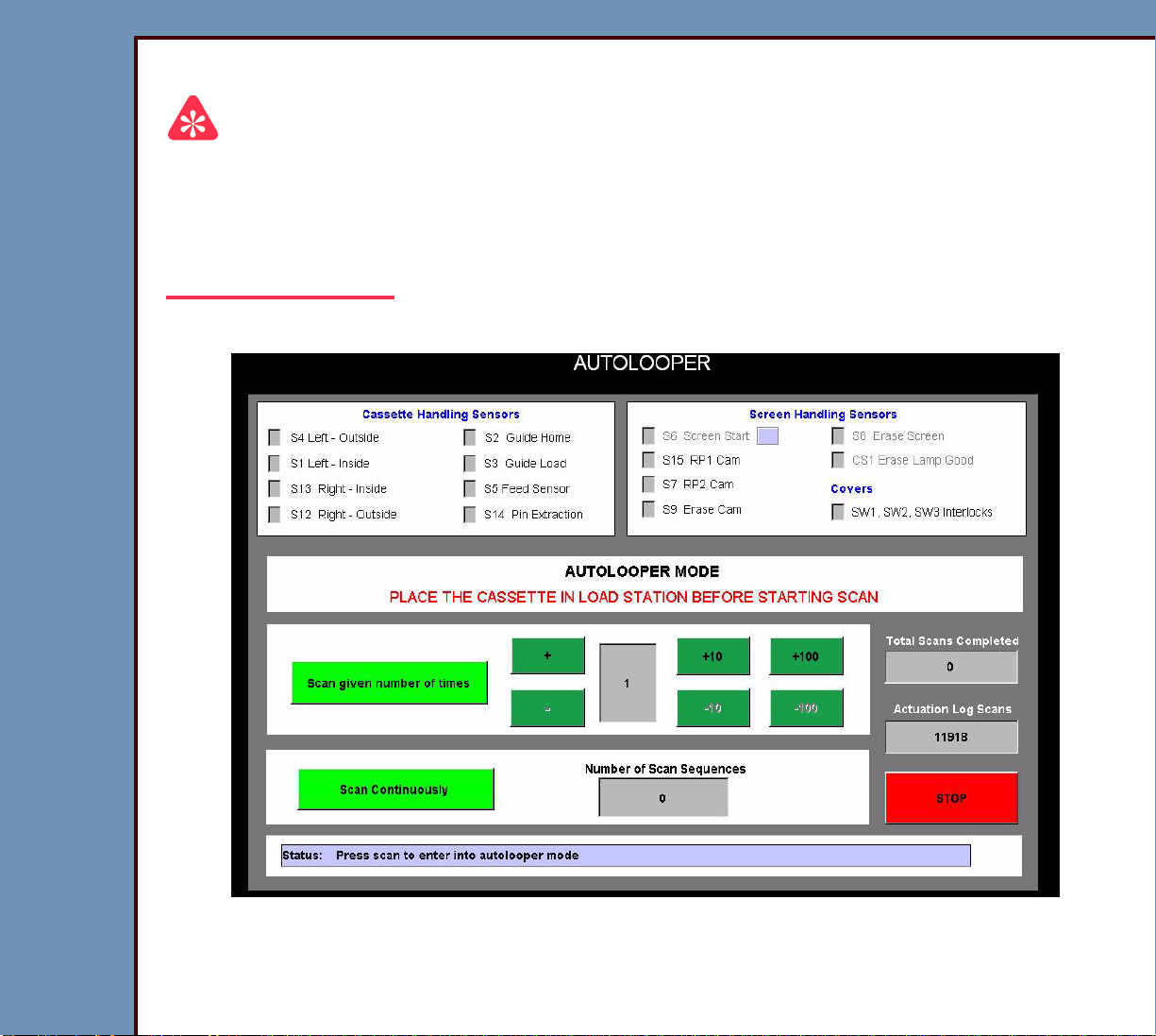
AUTOLOOPER
Important
You must have:
• LIGHT TEST set to enabled
• SLOW SCAN COVER installed
• LASER SAFETY COVER installed
1 On the “System Ser vice Diagnostic” screen, select [AutoLooper].
2 Inser t a CASSETTE into the CR 500 SYSTEM.
3 Use the [+] or [-] to set the “Number of Cycles” to 10.
Page 58

DIAGNOSTICS Using the Diagnostics
09OCT07
DG4366-1
Page
58 of 211
4 Select either :
• [Scan given number of times], or
• [Scan Continuously]
System Self Tests
1 On the “System Ser vice Diagnostic” screen, select [System Self Test].
2 Select [START MCPU SELF TEST].
3 Wait approximately 20 seconds for the test to complete.
Page 59
09OCT07
DG4366-1
Page
59 of 211
DIAGNOSTICS Using the Diagnostics
4 Obser ve the results for each test.
5 If any of the tests display “FAILED”, check the error logs. See Checking the Error Logs.
6 See the Error Codes to determine the possible cause and action for the problem.
Page 60

09OCT07
DG4366-1
Page
60 of 211
DIAGNOSTICS Using the Diagnostics
Diagnostic Procedures
Checking the Error Logs
1 On the “System Ser vice Diagnostic” screen, select [Error Log].
2 Select either :
• [Sort By Date],
• [Sort By ErrorCode], o r
• [Sort By CassetteID]
Page 61

DIAGNOSTICS Using the Diagnostics
09OCT07
DG4366-1
Page
61 of 211
Checking the Error Frequency Log
1 On the “System Ser vice Diagnostic” screen, select [Error Frequency Log].
2 Select either :
• [Sort By Date],
• [Sort By ErrorCode], o r
• [Sort ErrorFrequency]
Page 62

DIAGNOSTICS Using the Diagnostics
09OCT07
DG4366-1
Page
62 of 211
Checking the Actuation Logs
1 On the “System Ser vice Diagnostic” screen, select [Actuation Logs].
Page 63
DIAGNOSTICS Using the Diagnostics
09OCT07
DG4366-1
Page
63 of 211
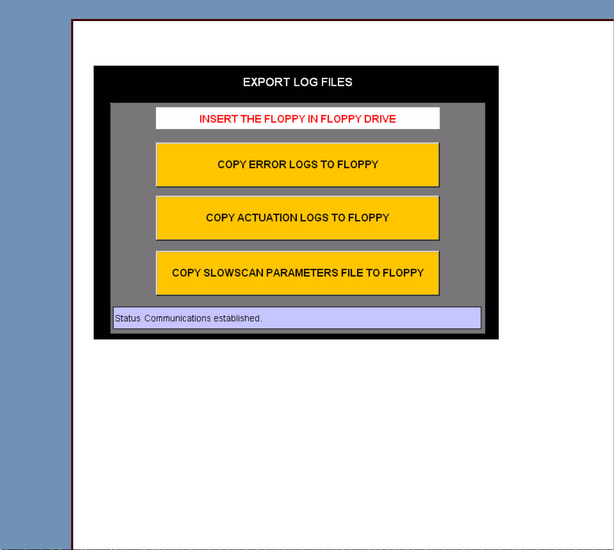
Storing the Error Logs on a Disk
1 On the “System Ser vice Diagnostic” screen, select [Export Log Files].
2 Inser t a disk into the DRIVE.
3 Select either :
• [COPY ERROR LOGS TO FLOPPY],
• [COPY ACTUATION LOGS TO FLOPPY], or
• [COPY SLOWSCAN PARAMETERS FILE TO FLOPPY]
Page 64

DIAGNOSTICS Using the Diagnostics
09OCT07
DG4366-1
Page
64 of 211
Clearing the Error Logs
1 On the “System Ser vice Diagnostic” screen, select [Clear Error Log].
2 Select [CLEAR ERROR LOG].
Page 65

DIAGNOSTICS Using the Diagnostics
09OCT07
DG4366-1
Page
65 of 211
Displaying the Software Versions
1 On the “System Ser vice Diagnostic” screen, select [Display Software Versions].
Page 66

DIAGNOSTICS Using the Diagnostics
09OCT07
DG4366-1
Page
66 of 211
2 Check that each BOARD has the correct communication:
Message Description Action
The version number
is in the field.
All fields are blank. The diagnostics is not
The BOARD is
“Responding”.
operating.
Check that the newest and correct
version of the software is installed.
1. Do a shutdown of the computer.
2. De-energize the CR 500
3. Energize the CR 500 SYSTEM.
“Not Responding”
Important
The message is normal
1. Check the connections to the
2. Download the software to the
during initialization.
Failure of communications
3. If you cannot successfully
to the BOARD.
“Not Repor ting” The BOARD has a failure of
1. Check the BOARD that is “Not
communication because
another BOARD is “Not
Responding”.
2. Do the test again.
SYSTEM.
BOARD.
BOARD.
download the software to the
BOARD, install a new BOARD.
Responding”.
Page 67

DIAGNOSTICS Using the Diagnostics
09OCT07
DG4366-1
Page
67 of 211
Downloading Software to the BOARDS
1 On the “System Ser vice Diagnostic” screen, select [Download to Circuit Boards].
Caution
Downloading the “SSC BOOT” can cause damage to the SLOW SCAN CONTROLLER
BOARD A6. Only download the “SSC BOOT” if necessar y.
2 Select either :
• [DOWNLOAD MSC APPLICATION],
• [DOWNLOAD SSC BOOT AND APPLICATIONS],
• [DOWNLOAD MCPU APPLICATION],
• [DOWNLOAD SSC APPLICATIONS], or
• [DOWNLOAD SSC PARAMET ERS]
Page 68

09OCT07
DG4366-1
Page
68 of 211
DIAGNOSTICS Error Codes
Section 2: Error Codes
Overview
The first 2 digits of the error code identify the subsystem or component with the error.
Example: 10003
The “1” and the “0” indicate that the error occurred in the subsystem CASSETTE LOAD.
1 Use Table 7 to help identify the component with the error.
2 Advance to the error code to diagnose the error.
Table 7 Subsystem
ID No. Subsystem
10 CASSETTE LOAD
12 SLOW SCAN AY
13 ERASE LAMPS
14 POWER SUPPLY
15 DATA PAT H
16 Calibration
19 “Self Test” for the MASTER CENTRAL PROCESSING UNIT
22 MECHANISM SYSTEM CONTROL BOARD
29 MECHANISM SYSTEM CONTROL BOARD RTXC
30 MECHANISM SYSTEM CONTROL BOARD SYSTEM
32 Communications for the MECHANISM SYSTEM CONTROL BOARD
Windows 2000 SUBSYSTEM
47 SHUTDOWN MANAGER
49 DISK MANAGER
54 Service Diagnostics
55 Installation
Page 69

09OCT07
DG4366-1
Page
69 of 211
DIAGNOSTICS Error Codes
ID No. Subsystem
59 CD/DVD SYSTEM
60 Security Audit
Page 70

09OCT07
DG4366-1
Page
70 of 211
DIAGNOSTICS Error Codes
CASSETTE LOAD
940 - Display only, no Log Message
Description: The SCANNER is energizing. Do not scan CASSETTES at this time.
Cause: The CR 500 SYSTEM is not fully energized.
Action: Wait for the CR 500 SYSTEM to fully energize.
941 - Display only, no Log Message
Description: The communications between the MASTER CENTRAL PROCESSING
UNIT BOARD A2 and the MOTION CONTROL SYSTEM BOARD A1
malfunctioned.
Cause: The CABLE between the MASTER CENTRAL PROCESSING UNIT BOARD A2
and the MOTION CONTROL SYSTEM BOARD A1 malfunctioned.
Action: 1. Check the CABLE.
2. If this error continues, call the Technical Service Center.
942 - Display only, no Log Message
Description: The bar code could not be read.
Cause: The BAR CODE READER could not read the bar code.
Action: 1. Insert the CASSETTE again.
2. Insert another CASSETTE.
950 - Display only, no Log Message
Description: The CR 500 SYSTEM malfunctioned.
Cause: More than one cause is possibl e. See the error codes displayed.
Action: 1. De-energize the CR 500 SYSTEM.
2. Energize the CR 500 SYSTEM.
3. If this error continues, call the Technical Service Center.
Page 71

09OCT07
DG4366-1
Page
71 of 211
DIAGNOSTICS Error Codes
951 - Display only, no Log Message
Description: The CASSETTE did not load.
Cause: More than one cause is possibl e. See the error codes displayed.
Action: 1. Select “Continue” to eject the CASSETTE.
2. Insert the CASSETTE again.
3. If this error continues, call the Technical Service Center.
952 - Display only, no Log Message
Description: The CASSETTE did not load.
Cause: More than one cause is possibl e. See the error codes displayed.
Action: 1. Select “Continue” to eject the CASSETTE.
2. Insert the CASSETTE again.
3. If this error continues, call the Technical Service Center.
953 - Display only, no Log Message
Description: The CASSETTE did not scan.
Cause: More than one cause is possibl e. See the error codes displayed.
Action: 1. Select “Continue” to erase the CASSETTE.
2. Insert a new CASSETTE.
3. If this error continues, call the Technical Service Center.
Page 72

09OCT07
DG4366-1
Page
72 of 211
DIAGNOSTICS Error Codes
954 - Display only, no Log Message
Description: The CASSETTE did not erase.
Cause: More than one cause is possibl e. See the error codes displayed.
Action: 1. Select “Continue” to eject the CASSETTE.
2. Insert the CASSETTE again.
3. Erase the CASSETTE.
4. If this error continues, call the Technical Service Center.
955 - Display only, no Log Message
Description: The CASSETTE did not eject.
Cause: More than one cause is possibl e. See the error codes displayed.
Action: 1. Select “Continue” to eject the CASSETTE.
2. Insert the CASSETTE again.
3. If this error continues, call the Technical Service Center.
956 - Display only, no Log Message
Description: The CASSETTE did not scan.
Cause: More than one cause is possibl e. See the error codes displayed.
Action: 1. Select “Continue” to eject the CASSETTE.
2. Insert the CASSETTE again.
3. If this error continues, de-energize the CR 500 SYSTEM.
4. Energize the CR 500 SYSTEM.
Page 73

09OCT07
DG4366-1
Page
73 of 211
DIAGNOSTICS Error Codes
957 - Display only, no Log Message
Description: The CASSETTE could not be scanned because the memor y is full.
Cause: The disk is full.
Action: Call the Technical Service Center.
958 - Display only, no Log Message
Description: The CR 500 SYSTEM is in recovery from a malfunction.
Cause: More than one cause is possibl e. See the error codes displayed.
Action: 1. Eject the CASSETTE.
2. Insert the CASSETTE again.
959 - Display only, no Log Message
Description: The CR 500 SYSTEM malfunctioned.
Cause: More than one cause is possibl e. See the error codes displayed.
Action: 1. De-energize the CR 500 SYSTEM.
2. Energize the CR 500 SYSTEM.
3. If this error continues, call the Technical Service Center.
960 - Display only, no Log Message
Description: The communications of the CR 500 SYSTEM malfunctioned.
Cause: More than one cause is possibl e. See the error codes displayed.
Action: 1. De-energize the CR 500 SYSTEM.
2. Energize the CR 500 SYSTEM.
3. If this error continues, call the Technical Service Center.
Page 74

09OCT07
DG4366-1
Page
74 of 211
DIAGNOSTICS Error Codes
961 - Display only, no Log Message
Description: The CR 500 SYSTEM is not able to load the SCREEN.
Cause: More than one cause is possibl e. See the error codes displayed.
Action: 1. Select “Continue” to release the CASSETTE.
2. Remove the CASSETTE.
3. Insert the CASSETTE again.
4. If this error continues, call the Technical Service Center.
962 - Display only, no Log Message
Description: The CR 500 SYSTEM is not able to scan the CASSETTE.
Cause: More than one cause is possibl e. See the error codes displayed.
Action: 1. Select “Continue” to eject the SCREEN.
2. Remove the CASSETTE.
3. Insert the CASSETTE again.
4. If this error continues, contact the Technical Service Center.
963 - Display only, no Log Message
Description: The CR 500 SYSTEM is not able to eject the SCREEN.
Cause: More than one cause is possibl e. See the error codes displayed.
Action: 1. Select “Retry” to eject the SCREEN.
2. If the SCREEN does not eject, select “Cancel” to release the CASSETTE.
3. Remove the SCREEN manually.
4. Insert another CASSETTE.
5. If this error continues, call the Technical Service Center.
Page 75

DIAGNOSTICS Error Codes
09OCT07
DG4366-1
Page
75 of 211
994 - Display only, no Log Message
Description: The CASSETTE was not loaded correctly into the CR 500 SYSTEM.
Cause: The CASSETTE was not inserted correctly.
Action: 1. Remove the CASSETTE.
2. Insert the CASSETTE again.
995 - Display only, no Log Message
Description: The CASSETTE was not scanned.
Cause: The CASSETTE was not scanned.
Action: 1. Remove the CASSETTE.
2. Insert the CASSETTE again.
996 - Display only, no Log Message
Description: The CASSETTE was not erased.
Cause: The CASSETTE was not erased.
Action: 1. Remove the CASSETTE.
2. Insert the CASSETTE again.
3. Erase the CASSETTE.
997 - Display only, no Log Message
Description: The CASSETTE was not scanned correctly.
Cause: The CASSETTE was not scanned.
Action: 1. Remove the CASSETTE.
2. Insert another CASSETTE.
Page 76

09OCT07
DG4366-1
Page
76 of 211
DIAGNOSTICS Error Codes
998 - Display only, no Log Message
Description: The CASSETTE was not ejected.
Cause: The CASSETTE was not ejected.
Action: 1. Remove the CASSETTE.
2. Insert another CASSETTE.
999 - Display only, no Log Message
Description: The CR 500 SYSTEM is energizing.
Cause: The CR 500 SYSTEM is not fully energized.
Action: Wait for the CR 500 SYSTEM to fully energize.
1000 - Display only, no Log Message
Description: The CR 500 SYSTEM is energized.
Cause: The CR 500 SYSTEM is energize d.
Action: Insert the CASSETTE.
1001 - Display only, no Log Message
Description: The CR 500 SYSTEM completed scanning.
Cause: The function is complete.
Action: Remove the CASSETTE.
10021 - MSC BOARD A1: Software malfunction
Description: The MECHANISM SYSTEM CONTROL BOARD A1 sent a command
that was not correct.
Cause 1: The software for the MECHANISM SYSTEM CONTROL BOARD A1
malfunctioned.
Action: Install the software again for the MECHANISM SYSTEM CONTROL BOARD A1.
Page 77

09OCT07
DG4366-1
Page
77 of 211
DIAGNOSTICS Error Codes
Cause 2: The MECHANISM SYSTEM CONTROL BOARD A1 malfunctioned.
Action: Do the checkout for the MECHANISM SYSTEM CONTROL BOARD A1.
10022 - MSC BOARD A1: Software malfunction
Description: The DRIVE ROLLER received a signal when waiting for an interrupt or
timeout to occur.
Cause 1: The software for the MECHANISM SYSTEM CONTROL BOARD A1
malfunctioned.
Action: Install the software again for the MECHANISM SYSTEM CONTROL BOARD A1.
Cause 2: The MECHANISM SYSTEM CONTROL BOARD A1 malfunctioned.
Action: Do the checkout for the MECHANISM SYSTEM CONTROL BOARD A1.
10024 - MSC BOARD A1: Software malfunction
Description: A timeout occurred setting up the motion for the DRIVE ROLLER.
Cause 1: The software for the MECHANISM SYSTEM CONTROL BOARD A1
malfunctioned.
Action: Install the software again for the MECHANISM SYSTEM CONTROL BOARD A1.
Cause 2: The MECHANISM SYSTEM CONTROL BOARD A1 malfunctioned.
Action: Do the checkout for the MECHANISM SYSTEM CONTROL BOARD A1.
Page 78

DIAGNOSTICS Error Codes
09OCT07
DG4366-1
Page
78 of 211
10030 - READER did not read the CASSETTE BAR CODE
Cause 1: The CASSETTE:
• has a bar code that you cannot read
• does not have a bar code
Action: Install the correct bar code.
Cause 2: The inter nal BAR CODE READER malfunctioned.
Action: 1. Check:
• alignment of the BAR CODE READER
• BAR CODE READER is not blocked
• connections to the BAR CODE READER
2. If the BAR CODE READER emits a beep when you insert a CASSETTE, but
the CASSETTE does not load, check the CONNECTOR XU3 between the BAR
CODE READER and the MECHANISM SYSTEM CONTROL BOARD A1.
3. If the BAR CODE READER does not emit a beep when you load a
CASSETTE, check the CONNECTOR XU3 between the BAR CODE READER
and the MECHANISM SYSTEM CONTROL BOARD A1.
10031 - Cannot home cassette guides
Description: The GUIDE HOME SENSOR S2 did not actuate at the correct time.
Cause 1: A mechanical bind occurred.
Action: Check the status of the GUIDE HOME SENSOR S2 - use Individual Component
Control.
Cause 2: The CASSETTE INTERFACE AY malfunctioned.
Action: Repair the CASSETTE INTERFACE AY.
Page 79

09OCT07
DG4366-1
Page
79 of 211
DIAGNOSTICS Error Codes
10032 - Cannot activate cassette load switch
Description: The GUIDE LOAD SENSOR S3 did not actuate at the correct time.
Cause 1: A mechanical bind occurred.
Action: Check the status of the GUIDE LOAD SENSOR S3 - use Individual Component
Control.
Cause 2: The CASSETTE INTERFACE AY malfunctioned.
Action: Repair the CASSETTE INTERFACE AY.
10033 - Cannot clamp the cassette correctly
Description: The GUIDE LOAD SENSOR S3 did not actuate at the correct time.
Cause 1: A mechanical bind occurred.
Action: Use the Individual Component Control to check the status:
• GUIDE HOME SENSOR S2
• GUIDE LOAD SENSOR S3
Cause 2: The CASSETTE INTERFACE AY malfunctioned.
Action: Repair the CASSETTE INTERFACE AY.
10034 - Unable to retract cassette feed pin
Description: The PIN EXTRACTION SENSOR S14 did not actuate at the correct time.
Cause 1: A mechanical bind occurred.
Action: Check the status of the PIN EXTRACTION SENSOR S14 - use Individual
Component Control.
Cause 2: The CASSETTE INTERFACE AY malfunctioned.
Action: Repair the CASSETTE INTERFACE AY.
10035 - Cannot home the feed motor
Description: The FEED SENSOR S5 did not actuate at the correct time.
Page 80

09OCT07
DG4366-1
Page
80 of 211
DIAGNOSTICS Error Codes
Cause 1: A mechanical bind occurred.
Action: Check the status of the FEED SENSOR S5 - use Individual Component Control.
Cause 2: The CASSETTE INTERFACE AY malfunctioned.
Action: Repair the CASSETTE INTERFACE AY.
10036 - Display only, no Log Message
Description: A CASSETTE is in the CR 500 SYSTEM.
Cause: A CASSETTE is in the CR 500 SYSTEM.
Action: Remove the CASSETTE.
Cause 2: The CASSETTE ENTRY SENSOR S1 malfunctioned.
Action: Check:
• status of the CASSETTE ENTRY SENSOR S1 - use Individual Component
Control
• LED DS19 on the MECHANISM SYSTEM CONTROL BOARD A1 changes
status
• power to the CASSETTE ENTRY SENSOR S1
• condition of the EMITTER and DETECTOR of the CASSETTE ENTRY
SENSOR S1
10037 - Retrying clamp cassette with guides
Description: The GUIDE LOAD SENSOR S3 did not actuate at the correct time.
Cause: More than one cause is possibl e. See the error codes displayed.
Action: Check the status of all the SENSORS - use Individual Component Control.
10038 - Retrying extract screen from cassette
Cause: The SCREEN START SENSOR S6 did not detect the SCREEN.
Action: Check the status of all the SENSORS - use Individual Component Control.
Page 81

DIAGNOSTICS Error Codes
09OCT07
DG4366-1
Page
81 of 211
10039 - BAR CODE read failure occurred
Cause 1: The CASSETTE:
• has a bar code that you cannot read
• does not have a bar code
Action: Install the correct bar code.
Cause 2: The inter nal BAR CODE READER malfunctioned.
Action: 1. Check:
• alignment of the BAR CODE READER
• BAR CODE READER is not blocked
• connections to the BAR CODE READER
2. If the BAR CODE READER emits a beep when you insert a CASSETTE, but
the CASSETTE does not load, check the CONNECTOR XU3 between the BAR
CODE READER and the MECHANISM SYSTEM CONTROL BOARD A1.
3. If the BAR CODE READER does not emit a beep when you load a
CASSETTE, check the CONNECTOR XU3 between the BAR CODE READER
and the MECHANISM SYSTEM CONTROL BOARD A1.
10040 - MSC BOARD A1: Software malfunction - RTXC timer allocation failure
Description: The CR 500 SYSTEM is not able to locate the RTXC TIMER during the
reading of the BAR CODE.
Cause 1: The software for the MECHANISM SYSTEM CONTROL BOARD A1
malfunctioned.
Action: Install the software again for the MECHANISM SYSTEM CONTROL BOARD A1.
Cause 2: The MECHANISM SYSTEM CONTROL BOARD A1 malfunctioned.
Action: Do the checkout for the MECHANISM SYSTEM CONTROL BOARD A1.
Page 82

09OCT07
DG4366-1
Page
82 of 211
DIAGNOSTICS Error Codes
10999 - MSC BOARD A1: Software malfunction
Description: A timeout occurred.
Cause 1: The software for the MECHANISM SYSTEM CONTROL BOARD A1
malfunctioned.
Action: Install the software again for the MECHANISM SYSTEM CONTROL BOARD A1.
Cause 2: The MECHANISM SYSTEM CONTROL BOARD A1 malfunctioned.
Action: Do the checkout for the MECHANISM SYSTEM CONTROL BOARD A1.
CASSETTE
Screen Return
Description: The SCREEN was not fully retur ned to the CASSETTE.
Cause 1: The TRANSPORT PAD is not pulling the SCREEN into the CASSETTE. The
TRANSPORT PAD:
• is worn
• has debris in the surface
Action: 1. Check the TRANSPORT PAD for:
• wear
• debris in the surface
2. If necessary, replace:
• TRANSPORT PAD
• CASSETTE
Cause 2: The SCREEN is:
• not flat
• “domed” or “bowl-shaped”
Action: Install a new SCREEN.
Page 83

09OCT07
DG4366-1
Page
83 of 211
DIAGNOSTICS Error Codes
SLOW SCAN AY
12009 - Caution! SLOW SCAN MOTOR drawing too much power
Cause: A malfunction occurred in one or more of the following components:
• COIL BOARD A7
• SLOW SCAN AY
Action: 1. Check for an obstruction.
2. Do the checkout for the SLOW SCAN CONTROLLER BOARD A6 a nd COIL
BOARD A7.
12012 - SLOW SCAN AY: Timeout Error
Description: The SCREEN did not move within the correct time.
Cause: A malfunction occurred in one or more of the following components:
• COIL BOARD A7
• SLOW SCAN AY
Action: 1. Check for an obstruction.
2. Do the checkout for the SLOW SCAN CONTROLLER BOARD A6 a nd COIL
BOARD A7.
12013 - SLOW SCAN AY: Timeout error
Description: The system software made a command for the SCREEN that was not
correct.
Cause: The MECHANISM SYSTEM CONTROL BOARD A1 malfunctioned.
Action: Do the checkout for the MECHANISM SYSTEM CONTROL BOARD A1.
12014 - MSC BOARD A1: Software Error for SLOW SCAN
Description: This error might occur duri ng the diagnostics if you start to move the
SCREEN before the SCREEN stops moving.
Page 84

09OCT07
DG4366-1
Page
84 of 211
DIAGNOSTICS Error Codes
Cause: The SLOW SCAN AY malfunctioned.
Action: Do the checkout for the SLOW SCAN CONTROLLER BOARD A6 and COIL
BOARD A7.
12100 - SLOW SCAN CONTROLLER BOARD A6: Software Error
Description: The SLOW SCAN AY will not move.
Cause: The SLOW SCAN CONTROLLER BOARD A6 malfunctioned.
Action: 1. Energize and de-energize the CR 500 SYSTEM.
2. Do the checkout for the SLOW SCAN CONTROLLER BOARD A6 a nd COIL
BOARD A7.
12101 - SLOW SCAN frequency locked range error while scanning
Caution
• This error indicates that the SLOW SCAN AY might have a problem in the
future.
• The image was scanned before the error occurred. This error does not cause
image artifacts.
Description: The speed of the SLOW SCAN AY is out of specification when doing a
scan on the SCREEN. This error is displayed only in the Error Log.
Cause: The speed of the SLOW SCAN AY is out of specification.
Action: Monitor the speed of the SLOW SCAN AY.
Page 85

09OCT07
DG4366-1
Page
85 of 211
DIAGNOSTICS Error Codes
12102 - SLOW SCAN stopped, position error while scanning
Caution
You might not be able to use the image.
Description: The SLOW SCAN AY stopped when doing a scan on a SCREEN. The
error message is displayed on the SCREEN.
Cause 1: A jam occurred in the SLOW SCAN.
Action: Check for an obstruction. Horizontal line artifacts on the image might indicate
where to check for the obstruction.
Cause 2: The SLOW SCAN MOTOR malfunctioned.
Action: 1. Check the operation of the SLOW SCAN MOTOR. Do the Slow Scan Current
and Velocity Tests.
2. If necessary, insta ll a new SLOW SCAN MOTOR.
12103 - SLOW SCAN stopped, frequency lock motion stalled error while scanning
Caution
You might not be able to use the image.
Description: The SLOW SCAN AY stopped when doing a scan on a SCREEN. The error
message is displayed on the SCREEN.
Cause 1: A jam occurred in the SLOW SCAN AY. Horizontal line artifacts on the image
might indicate where to check for the obstruction.
Action: Check for an obstruction.
Page 86

09OCT07
DG4366-1
Page
86 of 211
DIAGNOSTICS Error Codes
Cause 2: The SLOW SCAN MOTOR malfunctioned.
Action: 1. Check the operation of the SLOW SCAN MOTOR. Do the Slow Scan Current
and Velocity Tests.
2. If necessary, insta ll a new SLOW SCAN MOTOR.
12107 - SLOW SCAN: +24 V DC malfunction during scan
Cause 1: The POWER SUPPLY PS1 malfunctioned.
Action: Do the checkout for the POWER SUPPLY PS1.
Cause 2: The SLOW SCAN CONTROLLER BOARD A6 malfunctioned.
Action: Do the checkout for the SLOW SCAN CONTROLLER BOARD A6 and COIL
BOARD A7.
12108 - SLOW SCAN stopped during scan
Cause: The SLOW SCAN CONTROLLER BOARD A6 malfunctioned.
Action: Do the checkout for the SLOW SCAN CONTROLLER BOARD A6 and COIL
BOARD A7.
Page 87

DIAGNOSTICS Error Codes
09OCT07
DG4366-1
Page
87 of 211
12109 - SLOW SCAN stopped during scan
Cause: The SLOW SCAN CONTROLLER BOARD A6 malfunctioned.
Action: Do the checkout for the SLOW SCAN CONTROLLER BOARD A6 and COIL
BOARD A7.
12110 - SLOW SCAN did not communicate with the MOTION SYSTEM CONTROL
Description: The SLOW SCAN AY did not move because of a communication error
with the SLOW SCAN CONTROLLER BOARD A6.
Cause: The SLOW SCAN CONTROLLER BOARD A6 malfunctioned.
Action: Do the checkout for the SLOW SCAN CONTROLLER BOARD A6 and COIL
BOARD A7.
12111 - SLOW SCAN did not move
Cause: The SLOW SCAN CONTROLLER BOARD A6 malfunctioned.
Action: Do the checkout for the SLOW SCAN CONTROLLER BOARD A6 and COIL
BOARD A7.
12112 - SLOW SCAN did not move
Cause: The SLOW SCAN CONTROLLER BOARD A6 malfunctioned.
Action: Do the checkout for the SLOW SCAN CONTROLLER BOARD A6 and COIL
BOARD A7.
12113 - SLOW SCAN CONTROLLER BOARD A6: NVRAM malfunctioned
Cause: The SLOW SCAN CONTROLLER BOARD A6 malfunctioned.
Action: Do the checkout for the SLOW SCAN CONTROLLER BOARD A6 and COIL
BOARD A7.
Page 88

09OCT07
DG4366-1
Page
88 of 211
DIAGNOSTICS Error Codes
12115 - SLOW SCAN CONTROLLER BOARD A6: Software Error
Cause 1: The SLOW SCAN CONTROLLER BOARD A6 malfunctioned.
Action: Do the checkout for the SLOW SCAN CONTROLLER BOARD A6 and COIL
BOARD A7.
Cause 2: The MECHANISM SYSTEM CONTROL BOARD A1 malfunctioned.
Action: Do the checkout for the MECHANISM SYSTEM CONTROL BOARD A1.
12116 - SLOW SCAN CONTROLLER BOARD A6 did not communicate with MSC
Description: The SLOW SCAN AY did not stop moving before the next command to
move. This error indicates a communication error with the SLOW SCAN
CONTROLLER BOARD A6.
Cause 1: The SLOW SCAN CONTROLLER BOARD A6 malfunctioned.
Action: Do the checkout for the SLOW SCAN CONTROLLER BOARD A6 and COIL
BOARD A7.
Cause 2: The MECHANISM SYSTEM CONTROL BOARD A1 malfunctioned.
Action: Do the checkout for the MECHANISM SYSTEM CONTROL BOARD A1.
12120 - SLOW SCAN did not move
Cause: The SLOW SCAN CONTROLLER BOARD A6 malfunctioned.
Action: Do the checkout for the SLOW SCAN CONTROLLER BOARD A6 and COIL
BOARD A7.
12121 - SLOW SCAN did not move
Cause: The SLOW SCAN CONTROLLER BOARD A6 malfunctioned.
Action: Do the checkout for the SLOW SCAN CONTROLLER BOARD A6 and COIL
BOARD A7.
Page 89

09OCT07
DG4366-1
Page
89 of 211
DIAGNOSTICS Error Codes
12122 - SLOW SCAN COIL BOARD A7 malfunctioned
Description: The SLOW SCAN AY stopped or did not move at all.
Cause: The SLOW SCAN CONTROLLER BOARD A6 malfunctioned.
Action: Do the checkout for the SLOW SCAN CONTROLLER BOARD A6 and COIL
BOARD A7.
12123 - SLOW SCAN CONTROLLER BOARD A6: Software Error
Description: The MOTOR CONTROLLER for the SLOW SCAN AY malfunctioned.
Cause: The SLOW SCAN CONTROLLER BOARD A6 malfunctioned.
Action: Do the checkout for the SLOW SCAN CONTROLLER BOARD A6 and COIL
BOARD A7.
12124 - SLOW SCAN CONTROLLER BOARD A6: Software Error
Description: An error occurred when initializing the SLOW SCAN AY.
Cause: The SLOW SCAN CONTROLLER BOARD A6 malfunctioned.
Action: Do the checkout for the SLOW SCAN CONTROLLER BOARD A6 and COIL
BOARD A7.
12125 - SLOW SCAN COIL BOARD A7 malfunctioned
Description: The SLOW SCAN AY stopped or did not move at all.
Cause: The SLOW SCAN CONTROLLER BOARD A6 malfunctioned.
Action: Do the checkout for the SLOW SCAN CONTROLLER BOARD A6 and COIL
BOARD A7.
12126 - Caution! SLOW SCAN MOTOR is overheated
Description: The SLOW SCAN MOTOR was using excessive power and is too hot.
Page 90

09OCT07
DG4366-1
Page
90 of 211
DIAGNOSTICS Error Codes
Cause: Malfunction in one or more of the following:
• COIL BOARD A7
• SLOW SCAN AY
Action: 1. Check for an obstruction.
2. Do the checkout for the SLOW SCAN CONTROLLER BOARD A6 a nd COIL
BOARD A7.
12130 - SLOW SCAN CONTROLLER BOARD A6: Software Error
Cause: The SLOW SCAN CONTROLLER BOARD A6 malfunctioned.
Action: Do the checkout for the SLOW SCAN CONTROLLER BOARD A6 and COIL
BOARD A7.
12131 - SLOW SCAN CONTROLLER BOARD A6 did not communicate with MSC
Cause 1: The SLOW SCAN CONTROLLER BOARD A6 malfunctioned.
Action: Do the checkout for the SLOW SCAN CONTROLLER BOARD A6 and COIL
BOARD A7.
Cause 2: The MECHANISM SYSTEM CONTROL BOARD A1 malfunctioned.
Action: Do the checkout for the MECHANISM SYSTEM CONTROL BOARD A1.
12132 - SLOW SCAN CONTROLLER BOARD A6 did not communicate with MSC
Cause: The SLOW SCAN CONTROLLER BOARD A6 malfunctioned.
Action: Do the checkout for the SLOW SCAN CONTROLLER BOARD A6 and COIL
BOARD A7.
12201 - SLOW SCAN CONTROLLER BOARD A6: Programming Error
Cause: The SLOW SCAN CONTROLLER BOARD A6 malfunctioned.
Action: Do the checkout for the SLOW SCAN CONTROLLER BOARD A6 and COIL
BOARD A7.
Page 91

09OCT07
DG4366-1
Page
91 of 211
DIAGNOSTICS Error Codes
12202 to 12260 - SLOW SCAN CONTROLLER BOARD A6: “Memory
Command” Error
Cause: The SLOW SCAN CONTROLLER BOARD A6 malfunctioned.
Action: Do the checkout for the SLOW SCAN CONTROLLER BOARD A6 and COIL
BOARD A7.
Error
Code
Description
12202 Error occurred during downloading to the SLOW SCAN CONTROLLER BOARD A6.
12203 Memor y error on the SLOW SCAN CONTROLLER BOARD A6.
12204 Memor y error on the SLOW SCAN CONTROLLER BOARD A6.
12216 Communication error between the SLOW SCAN CONTROLLER BOARD A6 and the
MECHANISM SYSTEM CONTROL BOARD A1.
12217 Communication error between the SLOW SCAN CONTROLLER BOARD A6 and the
MECHANISM SYSTEM CONTROL BOARD A1. Error “EM17 - Receive Buffer
Overflow.”
12219 Error during downloading of code or parameters for the SLOW SCAN
CONTROLLER BOARD A6.
12220 Memor y error on the SLOW SCAN CONTROLLER BOARD A6. Error “EM20 - New
Bootstrap Program, Download all Boot and Program Modules.”
12221 Memor y error on the SLOW SCAN CONTROLLER BOARD A6.
12222 Checksum error occurred during downloading of code to the SLOW SCAN
CONTROLLER BOARD A6.
12223 Checksum error occurred during downloading of code to the SLOW SCAN
CONTROLLER BOARD A6.
12228 Error occurred during downloading of the code to the SLOW SCAN CONTROLLER
BOARD A6.
12230 Memor y error on the SLOW SCAN CONTROLLER BOARD A6. Error “EM30 - Host
Flash Download Copy Boot Memory Error.”
12240 Error occurs during downloading to the SLOW SCAN CONTROLLER BOARD A6.
Error “EM40 - Illegal Record Type.”
Page 92

09OCT07
DG4366-1
Page
92 of 211
DIAGNOSTICS Error Codes
Error
Code
Description
12241 Error occurs during downloading to the SLOW SCAN CONTROLLER BOARD A6.
Error “EM41 - Invalid Extended Address.”
12242 Error occurs during downloading to the SLOW SCAN CONTROLLER BOARD A6.
Error “EM42 - Invalid Erase Block ID.”
12243 Error occurs during downloading to the SLOW SCAN CONTROLLER BOARD A6.
Error “EM43 - Receive Record Checksum Error.”
12244 Error when initializing. Error “EM44 - File Sum of Record Checksum Error, Download
Program.”
12245 Program error. Error “EM45 - Boot Checksum Write Error.”
12246 Error occurs during downloading to the SLOW SCAN CONTROLLER BOARD A6.
Error “EM46 - FIX_APP Code Block Checksum Write Error.”
12247 Error occurs during downloading to the SLOW SCAN CONTROLLER BOARD A6.
Error “EM47 - Code Page Checksum Write Error.”
12248 Error “EM48 - Parameters Save Flash Error.”
12250 Error occurs during downloading to the SLOW SCAN CONTROLLER BOARD A6.
Error “EM50 - Flash Write Address Out Of Range.”
12251 Error occurs during downloading to the SLOW SCAN CONTROLLER BOARD A6.
Error “EM51 - Flash Program Error: Erase.”
12252 Error occurs during downloading to the SLOW SCAN CONTROLLER BOARD A6.
Error “EM52 - Flash Program Error: Low Voltage.”
12253 Error occurs during downloading to the SLOW SCAN CONTROLLER BOARD A6.
Error “EM53 - Flash Program Error: Program.”
12254 Error occurs during downloading to the SLOW SCAN CONTROLLER BOARD A6.
Error “EM54 - Flash Program Error: Sequence.”
12255 Error occurs during downloading to the SLOW SCAN CONTROLLER BOARD A6.
Error “EM55”
12260 Error recording the parameters to the SLOW SCAN CONTROLLER BOARD A6.
Error “EM60 - Parameters Save Flash Error.”
Page 93

09OCT07
DG4366-1
Page
93 of 211
DIAGNOSTICS Error Codes
12261 - Roller Pair 1 Cam Motor Timeout
Description: A MOTOR and DRIVE PULLEY rotate a CAM that opens and closes ROLLER
PAIR 1. A FLAG on the CAM SHAFT actuates an optical SENSOR to allow
the system to determine the rotation of the CAM. This error occurs if the
optical SENSOR does not detect the FLAG within the correct time. This error
is only reported to the Error Log.
Cause 1: The BELT:
• is broken
• fell off the PULLEY
Action: 1. Check the BELT for ROLLER PAIR 1.
2. If necessary:
a. install a new BELT
b. install the BELT to the PULLEYS
3. Check:
a. alignment of the PULLEYS
b. MOTOR
c. CAM SHAFT
Cause 2: One of the 2 PULLEYS is broken.
Action: 1. Check the 2 PULLEYS.
2. If necessary, install a new PULLEY.
Cause 3: Malfunction of:
• DRIVE MOTOR
• wires to DRIVE MOTOR
• MSC BOARD
Page 94

09OCT07
DG4366-1
Page
94 of 211
DIAGNOSTICS Error Codes
Action: 1. Check the operation of the DRIVE MOTOR. Use Individual Component
Control.
2. If necessary, install new par ts.
3. Do the checkout procedure for the MECHANISM SYSTEM CONTROL BOARD
A1.
Cause 4: An intermittent error can be caused by:
• FLAG not actuating the optical SENSOR
• SCREWS for optical SENSOR are over-tightened
Action: Install a new RP1 SENSOR. Do not over-tighten the SCREWS.
Page 95

09OCT07
DG4366-1
Page
95 of 211
DIAGNOSTICS Error Codes
12262 - Roller Pair 2 Cam Motor Timeout
Description: A MOTOR and DRIVE PULLEY rotate a CAM that opens and closes ROLLER
PAIR 2. A FLAG on the CAM SHAFT actuates an optical SENSOR to allow
the system to determine the rotation of the CAM. This error occurs if the
optical SENSOR does not detect the FLAG within the correct time. This error
is only reported to the Error Log.
Cause 1: The BELT:
• is broken
• fell off the PULLEY
Action: 1. Check the BELT for ROLLER PAIR 2.
2. If necessary:
a. install a new BELT
b. install the BELT to the PULLEYS
3. Check:
a. alignment of the PULLEYS
b. MOTOR
c. CAM SHAFT
Cause 2: One of the 2 PULLEYS is broken.
Action: 1. Check the 2 PULLEYS.
2. If necessary, install a new PULLEY.
Cause 3: Malfunction of:
• DRIVE MOTOR
• wires to DRIVE MOTOR
• MSC BOARD
Page 96

09OCT07
DG4366-1
Page
96 of 211
DIAGNOSTICS Error Codes
Action: 1. Check the operation of the DRIVE MOTOR. Use Individual Component
Control.
2. If necessary, install new par ts.
3. Do the checkout procedure for the MECHANISM SYSTEM CONTROL BOARD
A1.
Cause 4: An intermittent error can be caused by:
• FLAG not actuating the optical SENSOR
• SCREWS for optical SENSOR are over-tightened
Action: Install a new RP2 SENSOR. Do not over-tighten the SCREWS.
Page 97

09OCT07
DG4366-1
Page
97 of 211
DIAGNOSTICS Error Codes
12263 - Roller Pair 3 Cam Motor Timeout
Description: A MOTOR and DRIVE PULLEY rotate a CAM that opens and closes ROLLER
PAIR 3. A FLAG on the CAM SHAFT actuates an optical SENSOR to allow
the system to determine the rotation of the CAM. This error occurs if the
optical SENSOR does not detect the FLAG within the correct time. This error
is only reported to the Error Log.
Cause 1: The BELT:
• is broken
• fell off the PULLEY
Action: 1. Check the BELT for ROLLER PAIR 2.
2. If necessary:
a. install a new BELT
b. install the BELT to the PULLEYS
3. Check:
a. alignment of the PULLEYS
b. MOTOR
c. CAM SHAFT
Cause 2: One of the 2 PULLEYS is broken.
Action: 1. Check the 2 PULLEYS.
2. If necessary, install a new PULLEY.
Cause 3: Malfunction of:
• DRIVE MOTOR
• wires to DRIVE MOTOR
• MSC BOARD
Page 98

09OCT07
DG4366-1
Page
98 of 211
DIAGNOSTICS Error Codes
Action: 1. Check the operation of the DRIVE MOTOR. Use Individual Component
Control.
2. If necessary, install new par ts.
3. Do the checkout procedure for the MECHANISM SYSTEM CONTROL BOARD
A1.
12264 - Screen start sensor blocked
Description: The SCREEN START SENSOR S6 did not actuate at the correct time.
Cause 1: The SCREEN is not in the CASSETTE.
Action: Check that the SCREEN is in the CASSETTE.
Cause 2: The SCREEN START SENSOR S6 malfunctioned.
Action: Check the status of the SCREEN START SENSOR S6 - use Individual
Component Control.
Cause 3: The CASSETTE INTERFACE AY malfunctioned.
Action: Repair the CASSETTE INTERFACE AY.
Page 99

09OCT07
DG4366-1
Page
99 of 211
DIAGNOSTICS Error Codes
12265 - Screen start timeout. Screen did not enter reader
Description: The SCREEN START SENSOR S6 did not actuate at the correct time. The
SCREEN START SENSOR S6 is located between ROLLER PAIR 1 and the
scan line. The system attempts to extract the SCREEN up to 3 times. The first
2 failures cause an error message 10038 - Retrying extract screen from
cassette. The third failure displays error message 12265.
Cause 1: The SCREEN is not in the CASSETTE.
Action: Check that the SCREEN is in the CASSETTE.
Cause 2: The SCREEN is under the TRANSPORT PAD in the CASSETTE.
Action: Insert the SCREEN correctly in the CASSETTE.
Cause 3: The SCREEN cannot be pulled from the CASSETTE because of static.
Action: Use Kodak MIN-R SCREEN CLEANER WIPES, TL5280094 to clean both sides of
the CASSETTE.
Page 100

09OCT07
DG4366-1
Page
100 of 211
DIAGNOSTICS Error Codes
BAD
leading edge or
trailing edge view
BAD
leading edge or
trailing edge view
BAD
GOOD
BAD
trailing edge view
1.25 mm (0.050 in.) maximum
1.25 mm (0.050 in.) maximum
BAD
leading edge
3.05 mm (0.120 in.)
overall height
leading edge orleading edge or
trailing edge view
trailing edge
trailing edge
H195_1125DCA
H195_1125DC
leading edge
 Loading...