

Page 1
© EASTMAN KODAK COMPANY, 2006 HEALTH GROUP
Confidential
Restricted
Information
{Adjust/Replace}{Production}{Health Group}{ExternalAndInternal}
ADJUSTMENTS AND REPLACEMENTS
for the
Kodak DirectView CR 500 SYSTEM
Service Code: 4366
Important
Qualified service personnel must do these procedures.
Publication No. AR4366-1
06DEC05
Supersedes AR4366-1
29NOV04
H195_0016BCH195_0016BC
Page 2

ADJUSTMENTS AND REPLACEMENTS
06DEC05
AR4366-1
Page
2 of 219
PLEASE NOTE The information contained herein is based on the experience and knowledge relating to the
subject matter gained by Eastman Kodak Company prior to publication.
No patent license is granted by this information.
Eastman Kodak Company reserves the right to change this information without notice, and
makes no warranty, express or implied, with respect to this information. Kodak shall not be
liable for any loss or damage, including consequential or special damages, resulting from any
use of this information, even if loss or damage is caused by Kodak’s negligence or other fault.
This equipment includes parts and assemblies sensitive to damage from electrostatic
discharge. Use caution to prevent damage during all service procedures.
Table of Contents
Description Page
Adjustments. . . . . . . . . . . . . . . . . . . . . . . . . . . . . . . . . . . . . . . . . . . . . . . . . . . . . . . . . . . 5
GALVO AY - Center . . . . . . . . . . . . . . . . . . . . . . . . . . . . . . . . . . . . . . . . . . . . . . . . 5
FOLD MIRROR . . . . . . . . . . . . . . . . . . . . . . . . . . . . . . . . . . . . . . . . . . . . . . . . . . . . . 10
COLLECTOR AY - Tilt . . . . . . . . . . . . . . . . . . . . . . . . . . . . . . . . . . . . . . . . . . . . . . . 22
GALVO BOARD . . . . . . . . . . . . . . . . . . . . . . . . . . . . . . . . . . . . . . . . . . . . . . . . . . . . 28
EXTRACTION PIN . . . . . . . . . . . . . . . . . . . . . . . . . . . . . . . . . . . . . . . . . . . . . . . . . . 35
SCREEN - Skew. . . . . . . . . . . . . . . . . . . . . . . . . . . . . . . . . . . . . . . . . . . . . . . . . . . . 40
Replacements . . . . . . . . . . . . . . . . . . . . . . . . . . . . . . . . . . . . . . . . . . . . . . . . . . . . . . . . . 46
FRONT COVER . . . . . . . . . . . . . . . . . . . . . . . . . . . . . . . . . . . . . . . . . . . . . . . . . . . . 46
TOP COVER. . . . . . . . . . . . . . . . . . . . . . . . . . . . . . . . . . . . . . . . . . . . . . . . . . . . . . . 47
CPU. . . . . . . . . . . . . . . . . . . . . . . . . . . . . . . . . . . . . . . . . . . . . . . . . . . . . . . . . . . . . . 49
HARD DRIVE . . . . . . . . . . . . . . . . . . . . . . . . . . . . . . . . . . . . . . . . . . . . . . . . . . . . . . 56
EXTRACTION PIN . . . . . . . . . . . . . . . . . . . . . . . . . . . . . . . . . . . . . . . . . . . . . . . . . . 66
S1/S4 and S12/S13 SENSOR BOARDS - DETECTOR . . . . . . . . . . . . . . . . . . . . . 68
S1/S4 and S12/S13 SENSOR BOARDS - EMITTER . . . . . . . . . . . . . . . . . . . . . . . 70
CASSETTE INTERFACE AY . . . . . . . . . . . . . . . . . . . . . . . . . . . . . . . . . . . . . . . . . . 72
GUIDE MOTOR . . . . . . . . . . . . . . . . . . . . . . . . . . . . . . . . . . . . . . . . . . . . . . . . . . . . 75
M9 LEFT CASSETTE CLAMP MOTOR . . . . . . . . . . . . . . . . . . . . . . . . . . . . . . . . . 77
M3 FEED DRIVE MOTOR . . . . . . . . . . . . . . . . . . . . . . . . . . . . . . . . . . . . . . . . . . . . 80
LEFT CARRIAGE AY . . . . . . . . . . . . . . . . . . . . . . . . . . . . . . . . . . . . . . . . . . . . . . . . 83
LEFT CASSETTE CLAMP DRIVE BELT . . . . . . . . . . . . . . . . . . . . . . . . . . . . . . . . 85
M2 PIN EXTRACT MOTOR . . . . . . . . . . . . . . . . . . . . . . . . . . . . . . . . . . . . . . . . . . . 87
M10 RIGHT CLAMP MOTOR . . . . . . . . . . . . . . . . . . . . . . . . . . . . . . . . . . . . . . . . . 89
RIGHT CARRIAGE AY. . . . . . . . . . . . . . . . . . . . . . . . . . . . . . . . . . . . . . . . . . . . . . . 91
S5 FEED SENSOR . . . . . . . . . . . . . . . . . . . . . . . . . . . . . . . . . . . . . . . . . . . . . . . . . . 93
Page 3

ADJUSTMENTS AND REPLACEMENTS
06DEC05
AR4366-1
Page
3 of 219
S14 PIN EXTRACTION SENSOR . . . . . . . . . . . . . . . . . . . . . . . . . . . . . . . . . . . . . . 95
RP 1 PRESSURE ROLLER. . . . . . . . . . . . . . . . . . . . . . . . . . . . . . . . . . . . . . . . . . . 98
RP 1 DRIVE ROLLER . . . . . . . . . . . . . . . . . . . . . . . . . . . . . . . . . . . . . . . . . . . . . . . 100
RP 2 PRESSURE ROLLER. . . . . . . . . . . . . . . . . . . . . . . . . . . . . . . . . . . . . . . . . . . 104
RP 2 DRIVE ROLLER . . . . . . . . . . . . . . . . . . . . . . . . . . . . . . . . . . . . . . . . . . . . . . . 110
RP 1 ARM . . . . . . . . . . . . . . . . . . . . . . . . . . . . . . . . . . . . . . . . . . . . . . . . . . . . . . . . . 119
RP 2 ARM . . . . . . . . . . . . . . . . . . . . . . . . . . . . . . . . . . . . . . . . . . . . . . . . . . . . . . . . . 121
RP 1 and RP 2 DRIVE BELTS . . . . . . . . . . . . . . . . . . . . . . . . . . . . . . . . . . . . . . . . 123
DRIVE BELT TENSIONER. . . . . . . . . . . . . . . . . . . . . . . . . . . . . . . . . . . . . . . . . . . . 125
RP 1 and RP 2 CAM MOTOR. . . . . . . . . . . . . . . . . . . . . . . . . . . . . . . . . . . . . . . . . 127
SENSORS S10 and S11 . . . . . . . . . . . . . . . . . . . . . . . . . . . . . . . . . . . . . . . . . . . . . 129
RP 1 and RP 2 CAM POSITION SENSORS . . . . . . . . . . . . . . . . . . . . . . . . . . . . . 131
SLOW SCAN DRIVER BOARD. . . . . . . . . . . . . . . . . . . . . . . . . . . . . . . . . . . . . . . . 133
ERASE AY . . . . . . . . . . . . . . . . . . . . . . . . . . . . . . . . . . . . . . . . . . . . . . . . . . . . . . . . 136
ERASE LAMP HOUSING AY . . . . . . . . . . . . . . . . . . . . . . . . . . . . . . . . . . . . . . . . . 139
RP 3 DRIVE MOTOR BELT . . . . . . . . . . . . . . . . . . . . . . . . . . . . . . . . . . . . . . . . . . . 141
RP 3 CAM DRIVE BELT . . . . . . . . . . . . . . . . . . . . . . . . . . . . . . . . . . . . . . . . . . . . . 142
RP 3 CAM DRIVE MOTOR . . . . . . . . . . . . . . . . . . . . . . . . . . . . . . . . . . . . . . . . . . . 144
AC POWER MODULE . . . . . . . . . . . . . . . . . . . . . . . . . . . . . . . . . . . . . . . . . . . . . . . 146
POWER SUPPLY 1 and POWER SUPPLY 2 . . . . . . . . . . . . . . . . . . . . . . . . . . . . 148
S8 SCREEN ERASE SENSOR . . . . . . . . . . . . . . . . . . . . . . . . . . . . . . . . . . . . . . . . 151
S9 ERASE CAM SENSOR. . . . . . . . . . . . . . . . . . . . . . . . . . . . . . . . . . . . . . . . . . . . 153
M6 ERASE DRIVE MOTOR. . . . . . . . . . . . . . . . . . . . . . . . . . . . . . . . . . . . . . . . . . . 155
ERASE LAMP RELAY . . . . . . . . . . . . . . . . . . . . . . . . . . . . . . . . . . . . . . . . . . . . . . . 157
RP 3 DRIVE ROLLER . . . . . . . . . . . . . . . . . . . . . . . . . . . . . . . . . . . . . . . . . . . . . . . 160
RP 3 PRESSURE ROLLER. . . . . . . . . . . . . . . . . . . . . . . . . . . . . . . . . . . . . . . . . . . 162
ERASE LAMPS . . . . . . . . . . . . . . . . . . . . . . . . . . . . . . . . . . . . . . . . . . . . . . . . . . . . 164
SCREEN GUIDE ROLLER . . . . . . . . . . . . . . . . . . . . . . . . . . . . . . . . . . . . . . . . . . . . 167
PMT BOARD . . . . . . . . . . . . . . . . . . . . . . . . . . . . . . . . . . . . . . . . . . . . . . . . . . . . . . 169
SLOW SCAN AY . . . . . . . . . . . . . . . . . . . . . . . . . . . . . . . . . . . . . . . . . . . . . . . . . . . 172
SLOW SCAN MOTOR . . . . . . . . . . . . . . . . . . . . . . . . . . . . . . . . . . . . . . . . . . . . . . . 175
MECHANISM SYSTEM CONTROLLER (MSC) BOARD . . . . . . . . . . . . . . . . . . . . 177
COLLECTOR AY . . . . . . . . . . . . . . . . . . . . . . . . . . . . . . . . . . . . . . . . . . . . . . . . . . . 179
FOLD MIRROR . . . . . . . . . . . . . . . . . . . . . . . . . . . . . . . . . . . . . . . . . . . . . . . . . . . . . 182
GALVO BOARD . . . . . . . . . . . . . . . . . . . . . . . . . . . . . . . . . . . . . . . . . . . . . . . . . . . . 185
MASTER CENTRAL PROCESSING UNIT (MCPU)/DIGITIZER BOARD. . . . . . . . 189
LASER PREREGULATOR BOARD . . . . . . . . . . . . . . . . . . . . . . . . . . . . . . . . . . . . 192
MINI FAST SCAN AY. . . . . . . . . . . . . . . . . . . . . . . . . . . . . . . . . . . . . . . . . . . . . . . . 195
Additional Service Procedures . . . . . . . . . . . . . . . . . . . . . . . . . . . . . . . . . . . . . . . . . . . 198
Checking the PHOSPHOR SCREEN for “Curl” and “Flatness” . . . . . . . . . . . . 198
Doing a Calibration of the LASER . . . . . . . . . . . . . . . . . . . . . . . . . . . . . . . . . . . . 201
Setting the Laser Calibration Voltage. . . . . . . . . . . . . . . . . . . . . . . . . . . . . . . . . . 202
Page 4

ADJUSTMENTS AND REPLACEMENTS
06DEC05
AR4366-1
Page
4 of 219
Setting the Calibration . . . . . . . . . . . . . . . . . . . . . . . . . . . . . . . . . . . . . . . . . . . . . 203
Page 5
06DEC05
AR4366-1
Page
5 of 219
ADJUSTMENTS AND REPLACEMENTS Adjustments
Section 1: Adjustments
GALVO AY - Center
Adjustment Specification
Purpose: To set the correct position of the laser beam.
Specification: The laser beam is aligned with the TAB on the FOLD MIRROR.
Special Tools: LASER SAFETY GOGGLES TL-5693
Prerequisites:
None
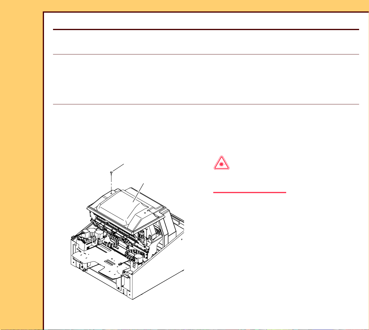
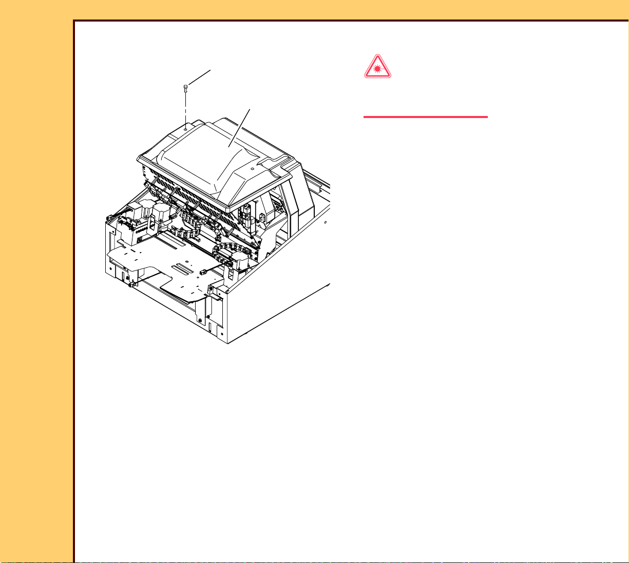
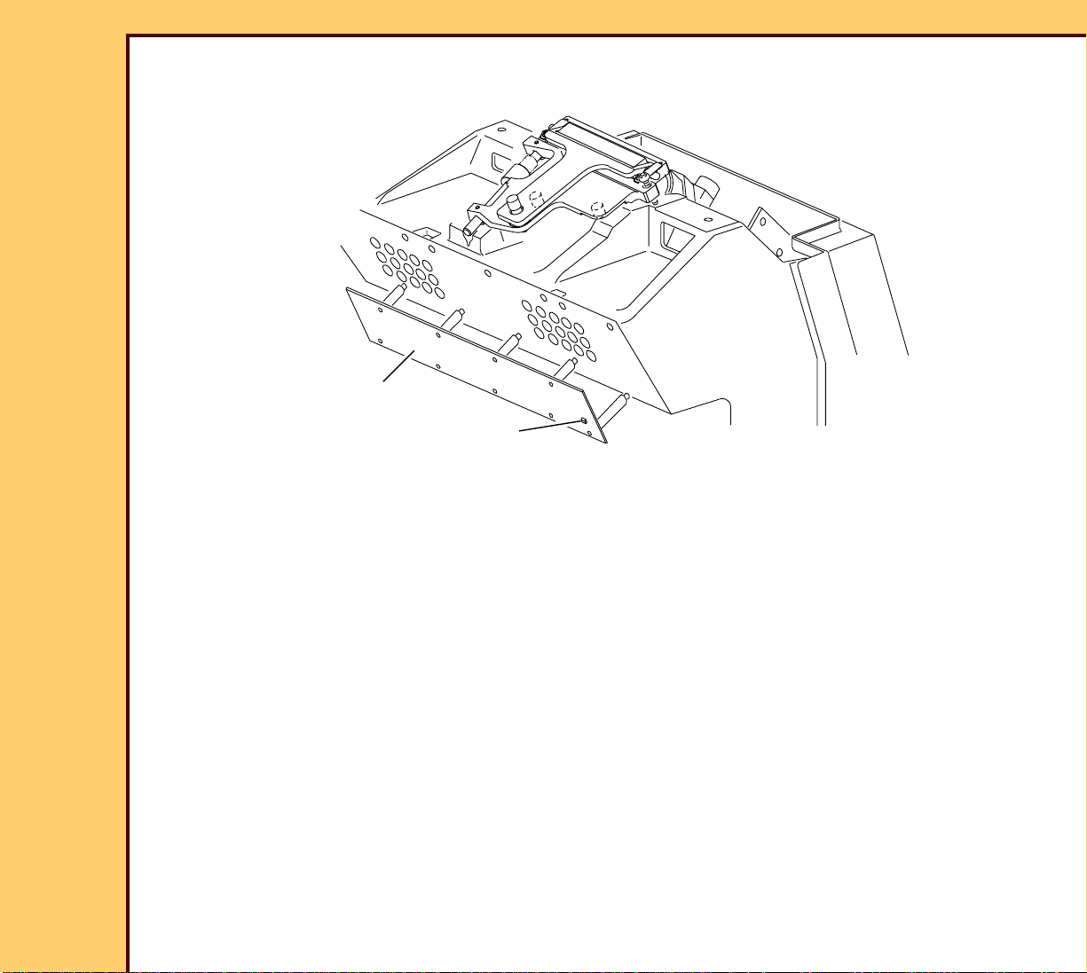
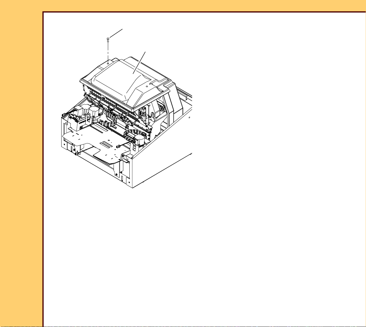
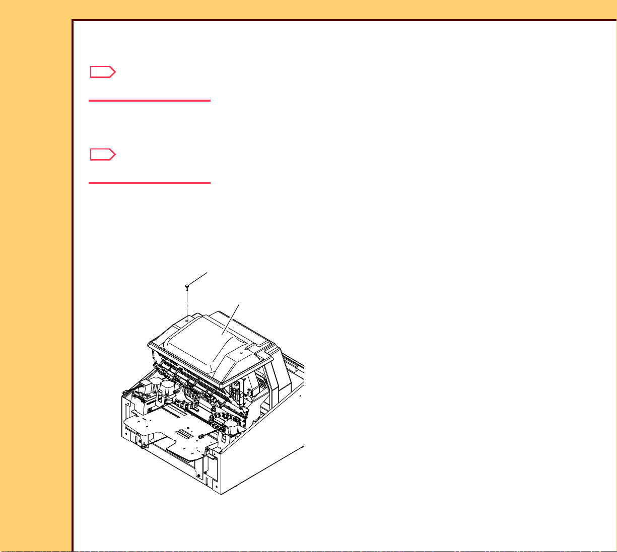
To Check:
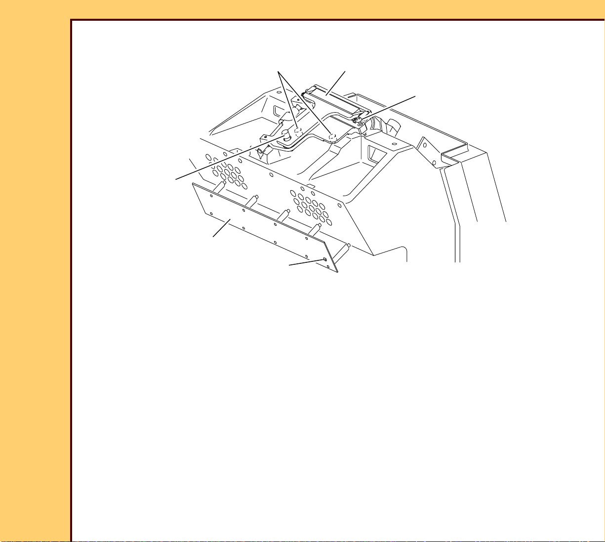
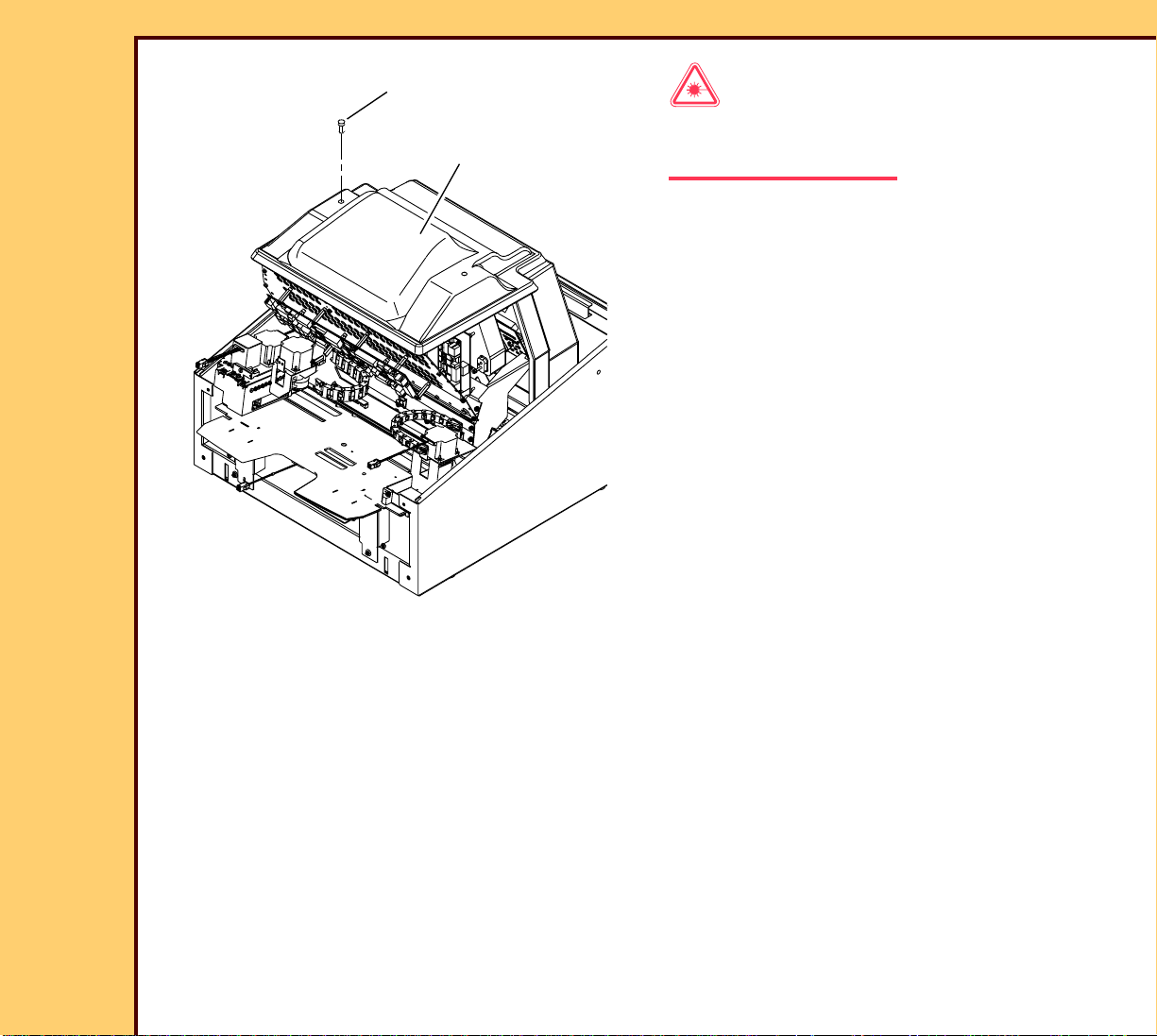
2 SCREWS
Laser Warning
LASER SAFETY
COVER
This equipment uses a visible red laser.
Prevent direct exposure to the laser beam.
H195_1020GCA
H195_1020GC
1 Remove:
• FRONT COVER
• TOP COVER
• 2 SCREWS
• LASER SAFETY COVER
Page 6
06DEC05
AR4366-1
Page
6 of 219
ADJUSTMENTS AND REPLACEMENTS Adjustments
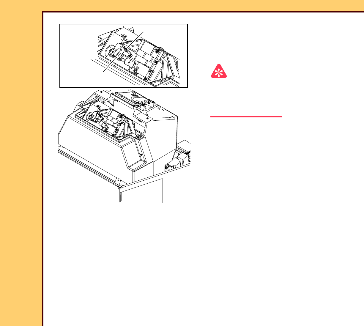
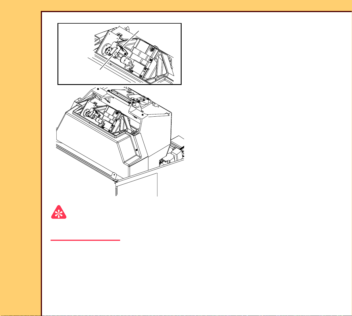
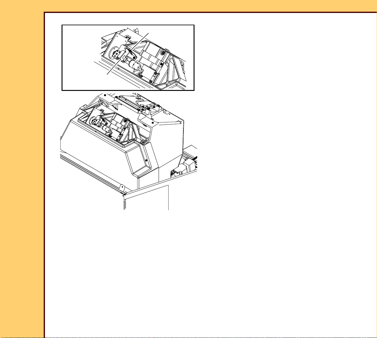
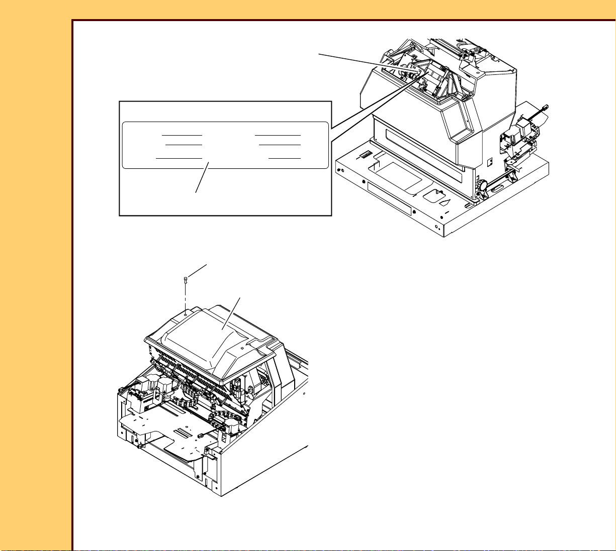
2 Loosen the THUMBSCREW.
THUMBSCREW
3 Move the LASER SAFETY FILTER into
the laser beam.
4 Tighten the THUMBSCREW.
LASER SAFETY
FILTER
H195_1023GCA
H195_1023GC
Important
For systems with software version ≥ 4.1, you
must have a “Session ID” for access to
“Service Functions” and “Diagnostics”. See
SERVICE BULLETIN 843.
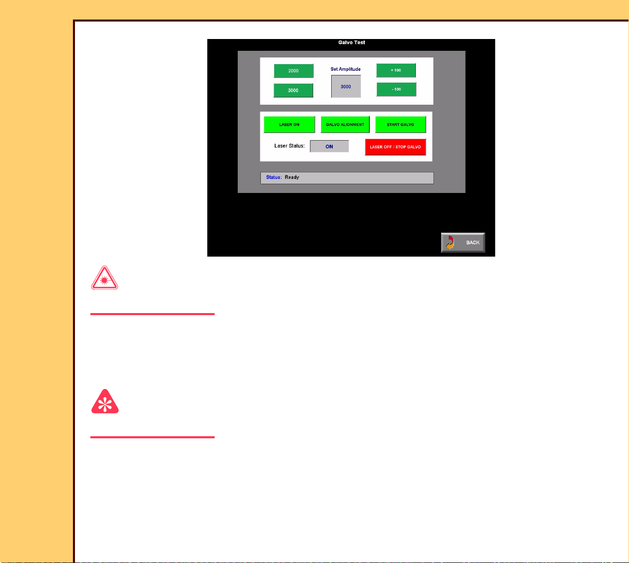
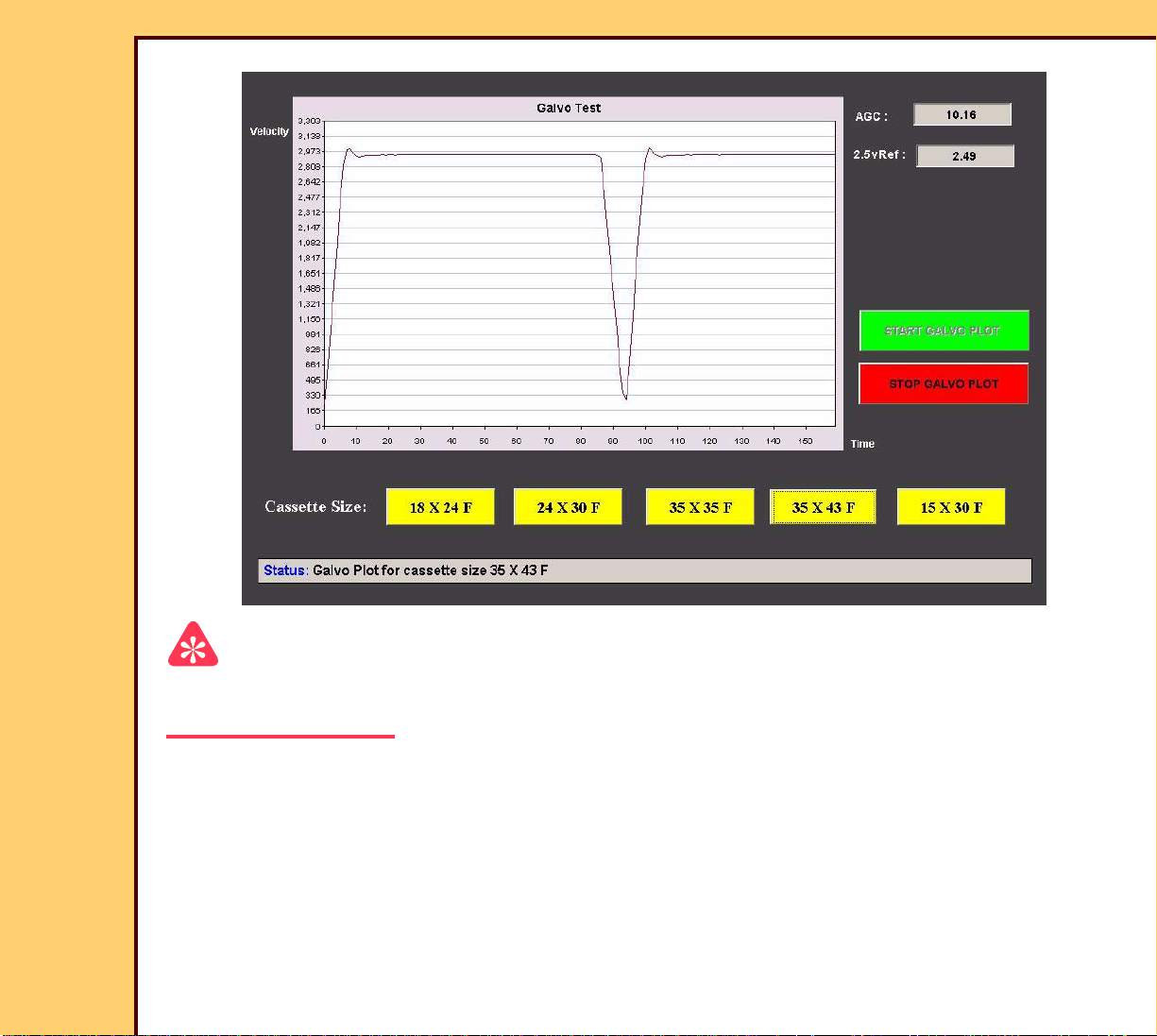
5 At the main menu, click:
• [Service Functions]
• [Diagnostics]
• [Galvo Test]
Page 7
06DEC05
AR4366-1
Page
7 of 219
ADJUSTMENTS AND REPLACEMENTS Adjustments
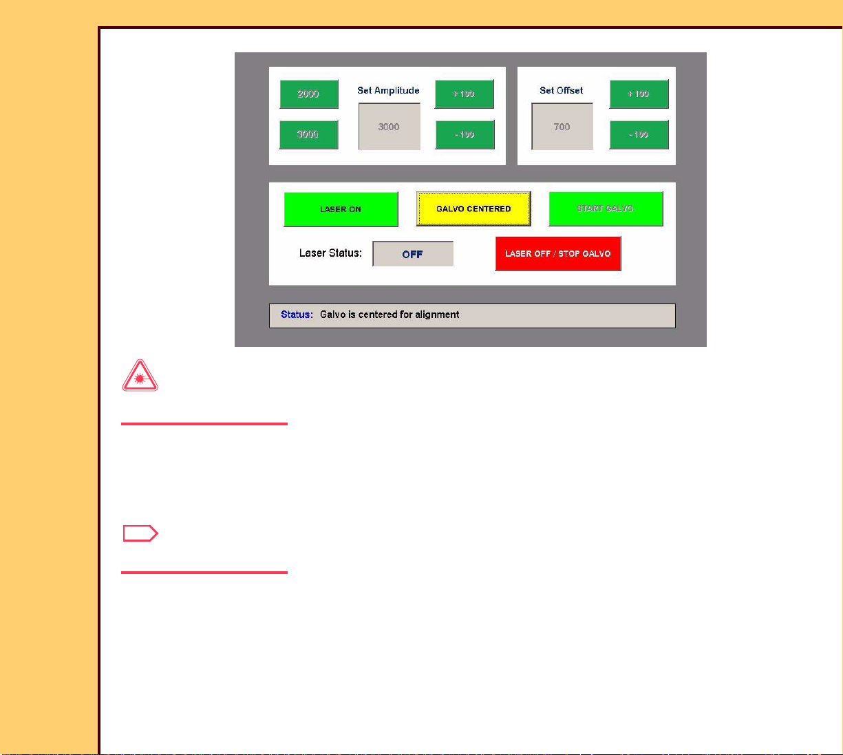
Laser Warning
This equipment uses a visible red laser. Prevent direct exposure to the laser beam.
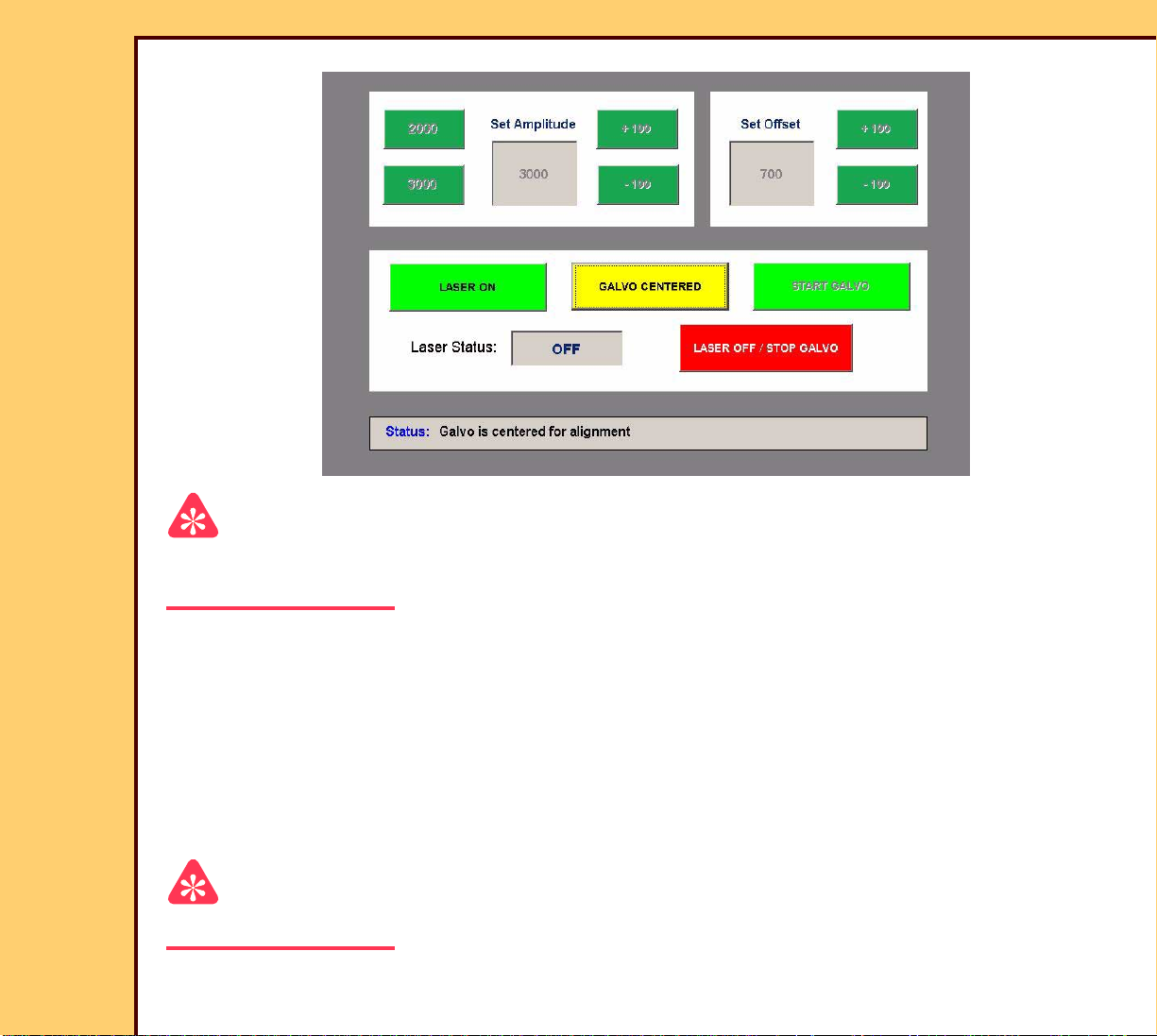
6 At the “Galvo Test” screen, click:
• [GALVO ALIGNMENT]
• [LASER ON]
Note
The [Galvo Alignment] BUTTON changes to [Galvo Centered].
Page 8
06DEC05
AR4366-1
Page
8 of 219
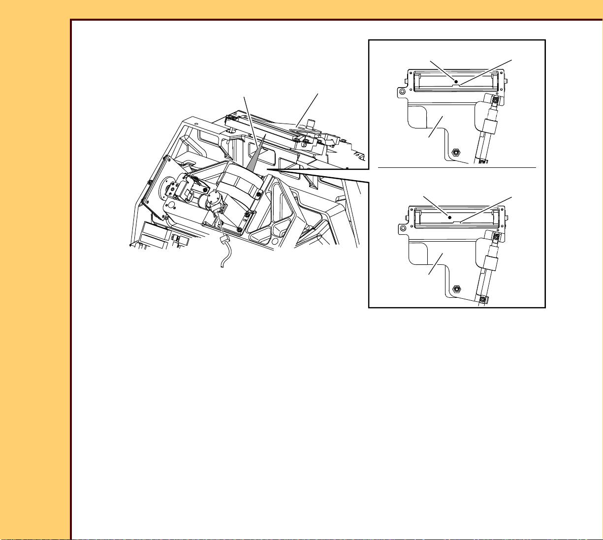
ADJUSTMENTS AND REPLACEMENTS Adjustments
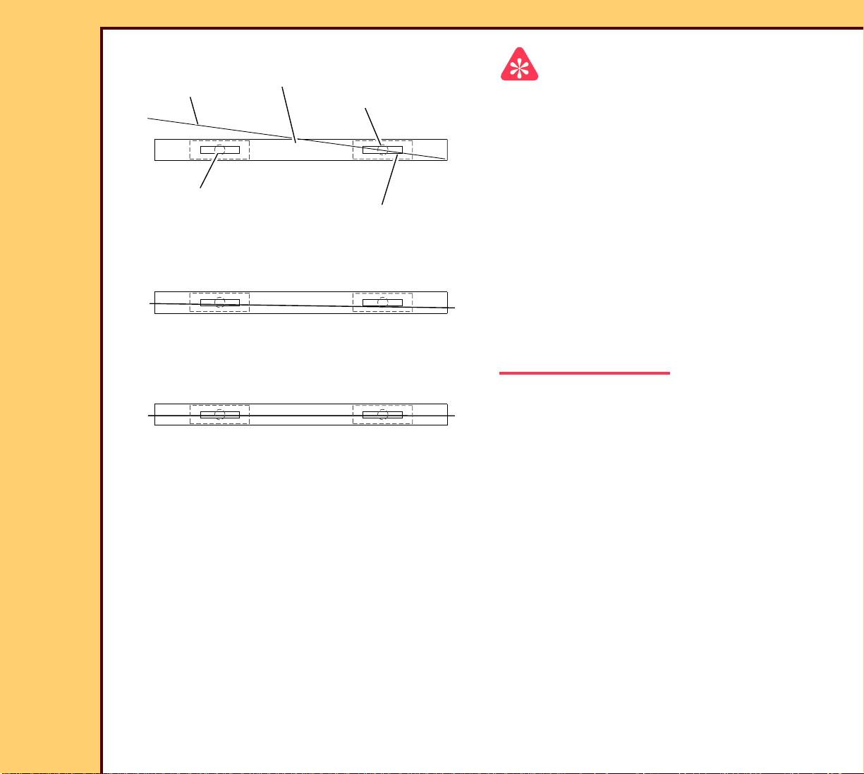
correct
laser beam
TAB
laser beam
FOLD MIRROR
FOLD MIRROR
not correct
laser beam
FOLD MIRROR
H195_1163HCB
H195_1163HC
7 Check that the laser beam is aligned with the TAB on the FOLD MIRROR.
TAB
Page 9
ADJUSTMENTS AND REPLACEMENTS Adjustments
06DEC05
AR4366-1
Page
9 of 219
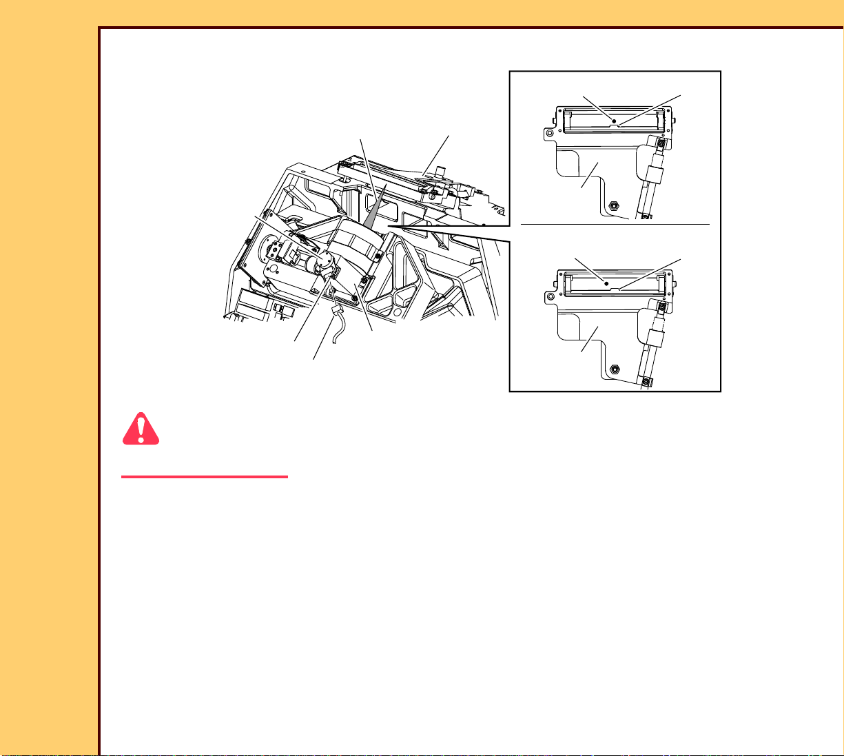
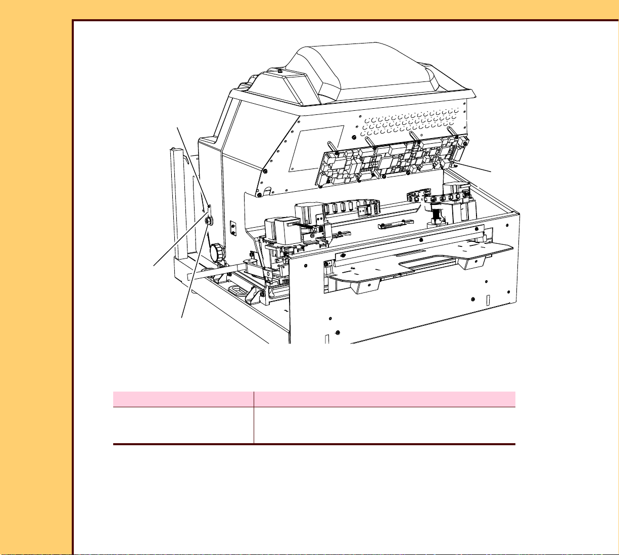
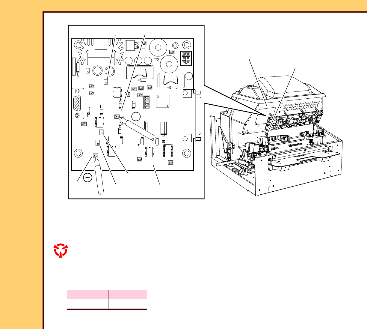
To Ad j u st :
GALVO
SCREW
GALVO CONNECTOR
H195_1163HCA
H195_1163HC
laser beam
GALVO
MOUNTING BRACKET
FOLD MIRROR
laser beam
FOLD MIRROR
laser beam
FOLD MIRROR
correct
TAB
not correct
TAB
Caution
electrical connections are exposed. Do not touch the GALVO CONNECTOR on the GALVO.
1 Loosen the SCREW on the GALVO MOUNTING BRACKET.
2 Rotate the GALVO until the laser beam is aligned with the center TAB on the FOLD
MIRROR.
3 Tighten the SCREW.
4 Click:
• “Stop Galvo”
• “LASER OFF”
Postrequisites:
1 Adjust the FOLD MIRROR.
Page 10

06DEC05
AR4366-1
Page
10 of 219
ADJUSTMENTS AND REPLACEMENTS Adjustments
FOLD MIRROR
Adjustment Specification
Purpose: To align the laser beam with the PHOTODIODES on the PLATEN.
Specification: The LED DS3 on the MECHANISM SYSTEM CONTROLLER (MSC)
BOARD illuminates amber.
Special Tools: LASER SAFETY GOGGLES TL-5693
Prerequisites:
1 Do the adjustment for the GALVO AY - Center.
Page 11
ADJUSTMENTS AND REPLACEMENTS Adjustments
06DEC05
AR4366-1
Page
11 of 219
To Check:
2 SCREWS
LASER SAFETY
COVER
Laser Warning
This equipment uses a visible red laser.
Prevent direct exposure to the laser beam.
1 Remove:
• If necessary, FRONT COVER
• If necessary, TOP COVER
• 2 SCREWS
• LASER SAFETY COVER
H195_1020GCA
H195_1020GC
Page 12
06DEC05
AR4366-1
Page
12 of 219
ADJUSTMENTS AND REPLACEMENTS Adjustments
2 Loosen the THUMBSCREW.
THUMBSCREW
3 Move the LASER SAFETY FILTER into
the laser beam.
4 Tighten the THUMBSCREW.
LASER SAFETY
FILTER
H195_1023GCA
H195_1023GC
Important
For systems with software version ≥ 4.1, you must have a “Session ID” for access to “Service
Functions” and “Diagnostics”. See SERVICE BULLETIN 843.
5 At the main menu, click:
• “Service Functions”
• “Diagnostics”
• “Galvo Test”
Page 13
06DEC05
AR4366-1
Page
13 of 219
ADJUSTMENTS AND REPLACEMENTS Adjustments
Laser Warning
This equipment uses a visible red laser. Prevent direct exposure to the laser beam.
6 Click:
• [LASER ON]
• [START GALVO]
Important
The Error Code 16028 might occur. Do not acknowledge this Error Code.
7 Increase the “Set Amplitude” to “3900”.
Page 14
06DEC05
AR4366-1
Page
14 of 219
ADJUSTMENTS AND REPLACEMENTS Adjustments
MSC BOARD
H195_1061BCB
LED DS3
H195_1061BC
8 Check that the LED DS3 on the MSC BOARD illuminates amber.
Page 15
ADJUSTMENTS AND REPLACEMENTS Adjustments
06DEC05
AR4366-1
Page
15 of 219
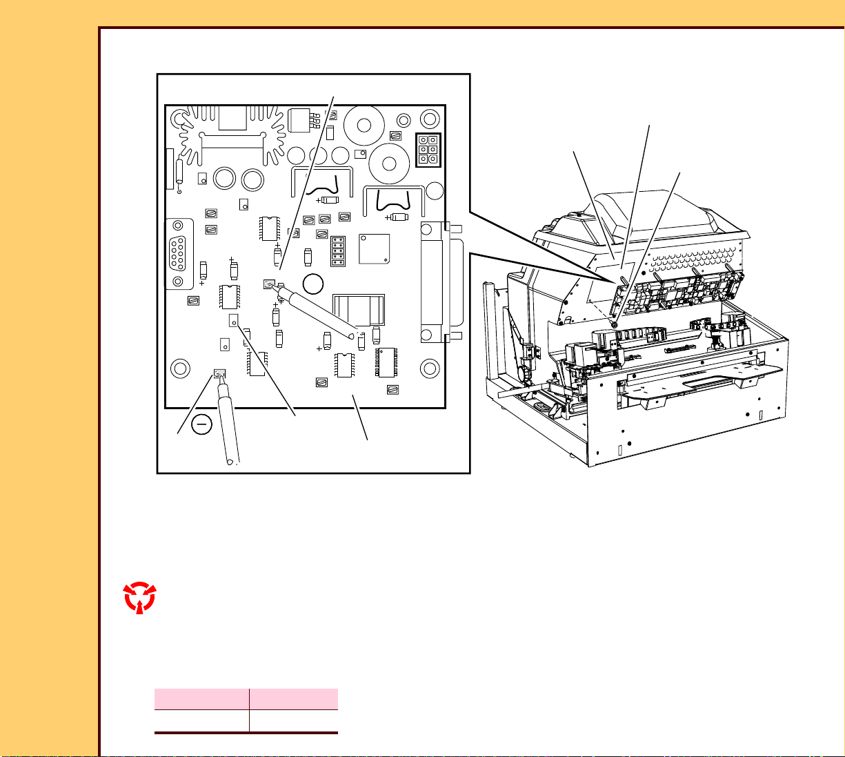
To Ad j u st :
GALVO BD
TP11
TP4
TP10
TP1 (-)
TP1
TP13 (+)
GALVO BOARD ACCESS PANEL
EMI BRACKET PANEL
6 SCREWS
+
TP15
TP12
U9
TP5
U4
TP16
U6
TP9
TP14
TP13
U8
U7
TP17
R2
GALVO BOARD
H195_1026HCC
H195_1026HC
1 Loosen the 6 SCREWS.
2 Remove the GALVO BOARD ACCESS PANEL.
3 Set the VOLTMETER to “DC”.
ESD
Possible damage from electrostatic discharge.
4 Connect the VOLTMETER on the GALVO BOARD to:
+ -
TP 13 TP 1
Page 16
ADJUSTMENTS AND REPLACEMENTS Adjustments
06DEC05
AR4366-1
Page
16 of 219
5 Click:
• [START GALVO PLOT]
• [35 x 43 F]
6 On the GALVO BOARD, rotate the POTENTIOMETER R2 until the VOLTMETER displays
9.0 ± 0.10 V DC.
7 Remove the VOLTMETER.
8 Install the GALVO BOARD ACCESS PANEL.
9 Tighten the 6 SCREWS.
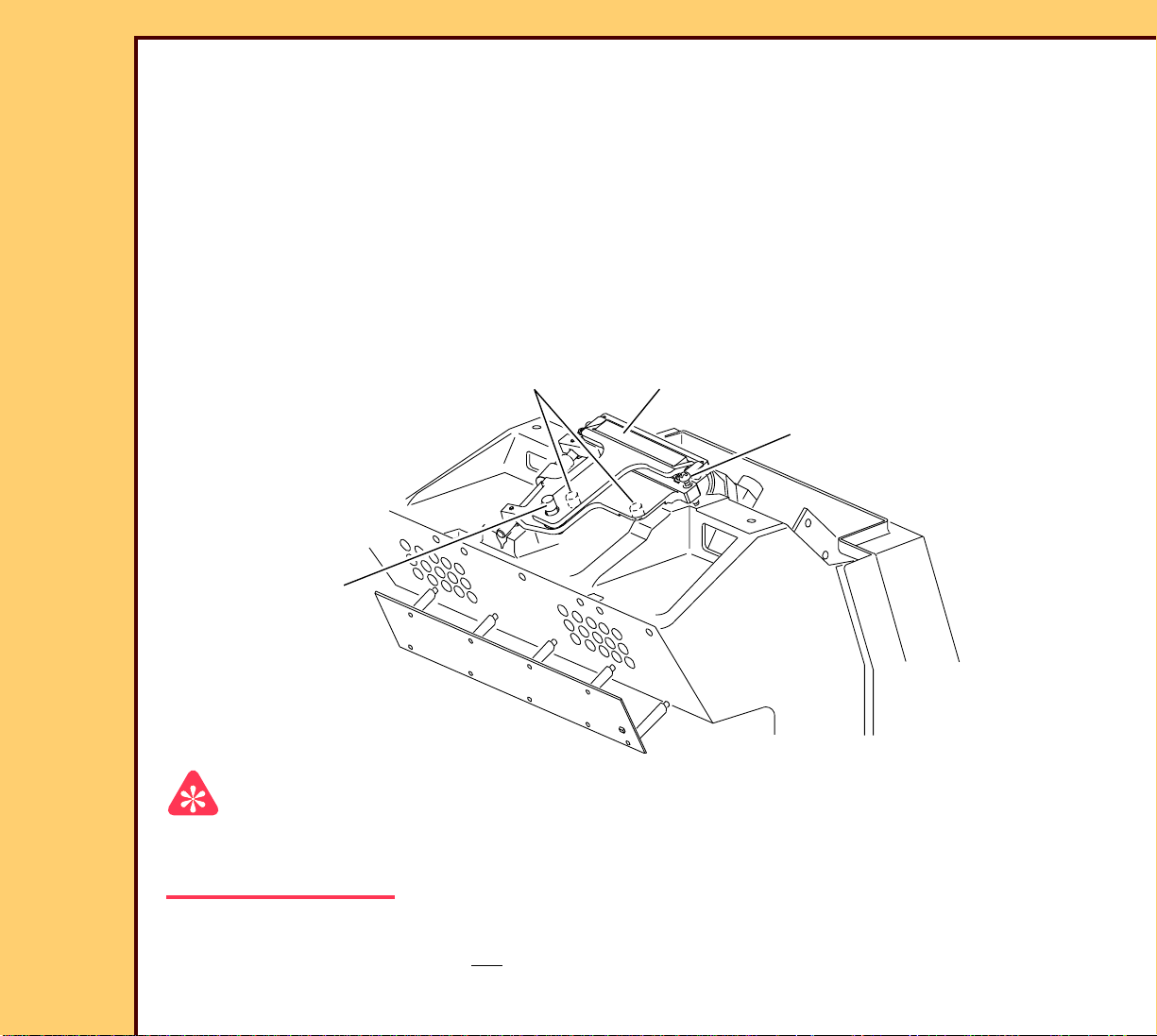
2 SPRINGS
THUMBSCREW
FOLD MIRROR
ADJUSTING
SCREW
H195_1061BCE
H195_1061BC
Important
• The THUMBSCREW adjusts the parallel position of the laser beam.
• The ADJUSTING SCREW adjusts the tilt of the beam
10 On the FOLD MIRROR, rotate both the THUMBSCREW and the ADJUSTING SCREW
until the 2 SPRINGS are not compressed.
Page 17
06DEC05
AR4366-1
Page
17 of 219
ADJUSTMENTS AND REPLACEMENTS Adjustments
2 SPRINGS
FOLD MIRROR
ADJUSTING
SCREW
THUMBSCREW
MSC BOARD
H195_1061BCA
LED DS3
H195_1061BC
Page 18
06DEC05
AR4366-1
Page
18 of 219
ADJUSTMENTS AND REPLACEMENTS Adjustments
beam
PLATEN
S11
Important
• The graphic is an example of the laser
beam from the FOLD MIRROR inside
the system.
a
• The beam is not visible for this
procedure.
• When the beam covers:
– S10 SENSOR, the LED DS3
illuminates red
– S11 SENSOR, the LED DS3
illuminates green
– S10 and S11 SENSORS, the LED
DS3 illuminates amber
11 Do:
a. Tighten the THUMBSCREW until the
LED DS3 on the MSC BOARD
illuminates green.
b. Using the THUMBSCREW to keep
the LED DS3 illuminated green,
rotate the ADJUSTING SCREW until
the LED DS3 illuminates amber.
b
c
H195_1161GCA
H195_1161GC
S10
2 SLOTS
c. With the LED DS3 illuminated
amber, rotate both the
THUMBSCREW and the
ADJUSTING SCREW to place the
beam in the center position of the
SLOT in the PLATEN.
Page 19
06DEC05
AR4366-1
Page
19 of 219
ADJUSTMENTS AND REPLACEMENTS Adjustments
2 SCREWS
Laser Warning
LASER SAFETY
COVER
This equipment uses a visible red laser.
Prevent direct exposure to the laser beam.
12 Click:
• [STOP GALVO]
• [LASER OFF]
13 Remove:
• 2 SCREWS
• LASER SAFETY COVER
H195_1020GCA
H195_1020GC
Page 20
06DEC05
AR4366-1
Page
20 of 219
ADJUSTMENTS AND REPLACEMENTS Adjustments
14 Loosen the THUMBSCREW.
THUMBSCREW
15 Move the LASER SAFETY FILTER from
the laser beam.
16 Tighten the THUMBSCREW.
LASER SAFETY
FILTER
H195_1023GCA
H195_1023GC
Page 21
06DEC05
AR4366-1
Page
21 of 219
ADJUSTMENTS AND REPLACEMENTS Adjustments
2 SCREWS
17 Install:
• LASER SAFETY COVER
LASER SAFETY
COVER
• 2 SCREWS
H195_1020GCA
H195_1020GC
Postrequisites:
1 Do the adjustment for the COLLECTOR AY - Tilt.
Page 22
06DEC05
AR4366-1
Page
22 of 219
ADJUSTMENTS AND REPLACEMENTS Adjustments
COLLECTOR AY - Tilt
Adjustment Specification
Purpose: To set the position of the COLLECTOR AY.
Specification: The LEDs Illuminate amber when the COLLECTOR AY is moved to the
center position using the “Scan Line Bow Magnitude”.
Special Tools: None
Prerequisites:
Caution
You must have the LASER SAFETY FILTER moved into the laser beam.
1 Adjust:
• GALVO AY - Center
• FOLD MIRROR
To Check:
You cannot check this adjustment.
To Ad j u st :
1 Remove:
• FRONT COVER
• TOP COVER
Caution
Dangerous Voltage
2 Energize the system.
Page 23
06DEC05
AR4366-1
Page
23 of 219
ADJUSTMENTS AND REPLACEMENTS Adjustments
Important
For systems with software version ≥ 4.1, you must have a “Session ID” for access to “Service
Functions” and “Diagnostics”. See SERVICE BULLETIN 843.
3 At the main menu, click:
• [Service Functions]
• [Diagnostics]
• [Galvo Test]
• [START GALVO]
• [LASER ON]
Important
The Error Code 16028 might occur, disregard the Error Code.
4 Set the “Galvo Amplitude” to 3900
Page 24
06DEC05
AR4366-1
Page
24 of 219
ADJUSTMENTS AND REPLACEMENTS Adjustments
COLLECTOR TILT
ADJUSTING NUT
LEDs
LOCKING
TAB
COLLECTOR
TILT SCREW
H195_1104HCA
H195_1104HC
5 Check that the LEDs illuminate amber.
6 Did the LEDs illuminate amber?
Yes No
Continue with Step 7. a. Do the adjustment for the FOLD MIRROR.
b. Do Steps 2 - 6 again.
7 Loosen the LOCKING TAB on the COLLECTOR TILT ADJUSTING NUT.
8 Rotate the COLLECTOR TILT SCREW clockwise 30 - 40 rotations until the LEDs
illuminate red, green or no color.
Page 25
ADJUSTMENTS AND REPLACEMENTS Adjustments
06DEC05
AR4366-1
Page
25 of 219
9 Rotate the COLLECTOR TILT SCREW counterclockwise until the LEDs illuminate amber
again.
Note
The COLLECTOR AY is at the end position.
10 Rotate the COLLECTOR TILT SCREW counterclockwise and record the number of
rotations until the LEDs change from amber to red, green or no color.
Note
The number of rotations is approximately 70 - 100.
11 To obtain the center position of the COLLECTOR AY, do the following formula:
number of rotations from Step 10 ÷ 2
example: 74 rotations ÷ 2 = 37
2 SCREWS
LASER SAFETY
COVER
12 Remove:
• 2 SCREWS
• LASER SAFETY COVER
H195_1020GCA
H195_1020GC
Page 26
06DEC05
H195_1105BC
Power High
Voltage High
Datecode
Scan Line Bow
Voltage Low
Power Low
Magnitude (+/-)
mW
V
mW
V
microns
H195_1105BCA
FASTSCAN
SCAN LINE BOW STICKER
AR4366-1
Page
26 of 219
ADJUSTMENTS AND REPLACEMENTS Adjustments
2 SCREWS
LASER SAFETY
COVER
H195_1020GCA
H195_1020GC
13 See the SCAN LINE BOW STICKER on
the FASTSCAN and record the “Scan
Line Bow Magnitude” from the
STICKER.
14 Install:
• LASER SAFETY COVER
• 2 SCREWS
Page 27

ADJUSTMENTS AND REPLACEMENTS Adjustments
06DEC05
AR4366-1
Page
27 of 219
15 Do the following formula:
“Scan Line Bow Magnitude” ÷ 40 = number of rotations for “Scan Line Bow”
Important
If the number of rotations for “Scan Line Bow” is:
• positive - you must add the number of rotations to the center position determined in
Step 11
• negative - you must subtract the number of rotations from the center position determined
in Step 11
16 Determine the new number of rotations for the COLLECTOR TILT SCREW, see the
examples:
Example 1:
• number of rotations = 74 ÷ 2 = 37
• number of rotations for “Scan Line Bow Magnitude” = -120 ÷ 40 = -3
• new number of rotations = 37 - 3 = 34 rotations
Example 2:
If you rotated the COLLECTOR TILT SCREW 74 rotations and the“Scan Line Bow
Magnitude” is -120 um, rotate the COLLECTOR TILT SCREW clockwise until the
LEDs illuminate amber then continue clockwise for 34 rotations to center the
“scanline” in the COLLECTOR.
17 Rotate the COLLECTOR TILT SCREW clockwise the new number of rotations obtained
in Step 16.
18 Tighten the LOCKING TAB.
19 Click:
• [STOP GALVO]
• [LASER OFF]
Page 28

ADJUSTMENTS AND REPLACEMENTS Adjustments
06DEC05
AR4366-1
Page
28 of 219
Postrequisites:
Do Setting the Calibration.
GALVO BOARD
Adjustment Specification
Purpose: To obtain the correct “Amplitude” of the “Collector Profile Screen”.
Specification: • The “Amplitude” of the “Collector Profile Screen” for the 35 x 43 F size
SCREEN is 3000
• The leading edge “Peak” on the GALVO PLOT CURVE is correct. See
the graphic on page 31.
Special Tools: VOLTMETER TL-3424
Prerequisites:
1 Do the adjustment procedure for the:
• GALVO AY - Center
± 100.
• FOLD MIRROR
• COLLECTOR AY - Tilt
To Check:
1 You cannot check this adjustment.
To Ad j u st :
Laser Warning
This equipment uses a visible red laser. Prevent direct exposure to the laser beam.
Page 29
06DEC05
AR4366-1
Page
29 of 219
ADJUSTMENTS AND REPLACEMENTS Adjustments
R1
TP13 (+)
EMI BRACKET PANEL
6 SCREWS
GALVO BD
TP10
TP11
TP4
TP1
U6
TP9
TP14
TP13
U8
U7
TP17
+
TP15
TP12
U9
TP5
U4
TP16
R2
TP1 (-)
R112
GALVO BOARD
H195_1026HCB
H195_1026HC
1 Loosen the 6 SCREWS.
2 Remove the GALVO BOARD ACCESS PANEL.
3 Set the VOLTMETER to “DC”.
ESD
Possible damage from electrostatic discharge.
4 Connect the VOLTMETER on the GALVO BOARD to:
+ -
TP 13 TP 1
Page 30
06DEC05
AR4366-1
Page
30 of 219
ADJUSTMENTS AND REPLACEMENTS Adjustments
Important
For systems with software version ≥ 4.1, you must have a “Session ID” for access to “Service
Functions” and “Diagnostics”. See SERVICE BULLETIN 843.
5 At the main menu, click:
• [Service Functions]
• [Diagnostics]
• [Galvo Plot]
• [Start Galvo Plot]
• [35 x 43 F]
Page 31

ADJUSTMENTS AND REPLACEMENTS Adjustments
06DEC05
AR4366-1
Page
31 of 219
GALVO PLOT CURVE
Not Correct
Peak
Velocity
H195_0064BCA
H195_0064BC
3.195
3.035
2.876
2.716
2.556
2.396
2.236
2.077
1.917
Velocity
horizontal level
3.195
3.035
2.876
2.716
2.556
2.396
2.236
2.077
1.917
Velocity
6 Is the leading edge “Peak” on the GALVO PLOT CURVE correct?
Yes No
Advance to Step 8. Continue with Step 7.
Not CorrectCorrect
3.195
3.035
2.876
2.716
2.556
2.396
2.236
2.077
1.917
7 Rotate the POTENTIOMETER R1:
• until the leading edge “Peak” of the GALVO PLOT CURVE extends above the
horizontal level.
• back until the leading edge “Peak” on the GALVO PLOT CURVE matches the
horizontal level.
8 Click:
• [BACK]
• [Galvo Test]
• [Start Galvo]
9 Set the VOLTMETER to “AC”.
Page 32

ADJUSTMENTS AND REPLACEMENTS Adjustments
06DEC05
AR4366-1
Page
32 of 219
10 On the GALVO BOARD, rotate the POTENTIOMETER R112 until the minimum AC
voltage is
obtained.
Note
This is the lowest value.
11 Click:
• [BACK]
• [Galvo Plot]
• [START GALVO PLOT]
• [35 x 43 F]
Velocity
Peak
3.195
3.035
2.876
2.716
2.556
2.396
2.236
2.077
1.917
Velocity
Not Correct
3.195
3.035
2.876
2.716
2.556
2.396
2.236
2.077
1.917
Velocity
Not CorrectCorrect
3.195
3.035
2.876
2.716
2.556
2.396
2.236
2.077
1.917
H195_0064BCA
H195_0064BC
horizontal level
12 Is the leading edge “Peak” on the GALVO PLOT CURVE correct?
Yes No
Continue with Step 13. Do Steps 7 - 12 again.
Page 33

ADJUSTMENTS AND REPLACEMENTS Adjustments
06DEC05
AR4366-1
Page
33 of 219
13 Using the 35 x 43 cm CASSETTE, do the following:
• Preparing the CASSETTES
• Preparing the Room
• Preparing the Equipment
• Cleaning the PHOSPHOR SCREEN
• Exposing the CASSETTE
• Doing a Calibration for the Scan
14 Click:
• [GET COLLECTOR PROFILES]
• [35 x 43 F]
Page 34

ADJUSTMENTS AND REPLACEMENTS Adjustments
06DEC05
AR4366-1
Page
34 of 219
15 Is the “amplitude” 3000 ± 100 counts?
Yes No
a. Click [BACK].
Continue with Step 16.
b. Advance to Step 18.
16 Is the “amplitude”?
Too Low To o H i g h
a. Set the VOLTMETER to “DC”.
b. Rotate R2 to increase the DC voltage
by 150 mV for every 100 counts.
c. Do Steps 5 - 15 again.
17 Remove the VOLTMETER.
18 Install:
• EMI BRACKET PANEL
• 6 SCREWS
• FRONT COVER
a. Set the VOLTMETER to “DC”.
b. Rotate R2 to decrease the DC voltage
by 150 mV for every 100 counts.
c. Do Steps 5 - 15 again.
• TOP COVER
Postrequisites:
1 None
Page 35

06DEC05
AR4366-1
Page
35 of 219
ADJUSTMENTS AND REPLACEMENTS Adjustments
EXTRACTION PIN
Adjustment Specification
Purpose: To set the correct position of the EXTRACTION PIN.
Specification: The distance between the MECH PLATE and the surface outside of the
FEED PIN is 143 ± 0.25 mm (5.667 ± 0.010 in.).
Special Tools: None
Prerequisites:
1 Remove:
• FRONT COVER
• TOP COVER
To Check:
Important
For systems with software version ≥ 4.1, you
must have a “Session ID” for access to
“Service Functions” and “Diagnostics”. See
SERVICE BULLETIN 843.
1 At the Main Menu, click:
• [Service Functions]
• [Diagnostics]
• [Individual Component Control]
• [EXTEND]
2 Under “PIN EXTRACTION”, click
[EXTEND]
Page 36

06DEC05
AR4366-1
Page
36 of 219
ADJUSTMENTS AND REPLACEMENTS Adjustments
3 Place the RULER against the MECH
FEED MOTOR HOME
SENSOR FLAG
PLATE.
4 Check that the distance between the
ADJUSTING
SCREW
MECH PLATE and the center of the
FEED PIN is 143 ± 0.25 mm
(5.667 ± 0.010 in.).
LOCKING
SCREW
MOUNTING
SCREW
+
_
0.25 mm
FEED PIN
143
(5.667
+
_
0.010 in.)
MECH PLATE
RULER
H195_1018GCA
H195_1018GC
To Ad j u st :
1 Loosen the LOCKING SCREW on the FEED MOTOR HOME SENSOR FLAG.
2 Rotate the ADJUSTING SCREW clockwise or counterclockwise.
3 Under “FEED MOTOR”, click:
• [EXTRACT]
• [HOME]
4 Click [RESET].
5 Wait until the “RESET” is completed.
Page 37

ADJUSTMENTS AND REPLACEMENTS Adjustments
06DEC05
AR4366-1
Page
37 of 219
6 Check that the distance between the MECH PLATE and the center of the FEED PIN is
143 ± 0.25 mm (5.667 ± 0.010 in.).
7 Is the distance correct?
Yes No
Continue with Step 8. Do Steps 2 - 7 again.
8 Tighten the LOCKING SCREW
9 Click:
• [BACK]
• [TRANSPORT]
10 Install the CASSETTE into the FEED
TRAY.
FEED
TRAY
35 x 43 CM
CASSETTE
TUBE SIDE
H195_1019GCA
H195_1019GC
Page 38

06DEC05
AR4366-1
Page
38 of 219
ADJUSTMENTS AND REPLACEMENTS Adjustments
11 Click:
• [+] or [-] until “1” displays
• [Cycle given number of times]
12 Did the system complete the cycle?
Yes No
Continue with Step 13. Do Steps 1 - 7 again.
13 Remove the CASSETTE.
Page 39

06DEC05
AR4366-1
Page
39 of 219
ADJUSTMENTS AND REPLACEMENTS Adjustments
CR 500 SYSTEM CASSETTE
open close
T U B E S I D E
CASSETTE DOOR
H195_1193BCA
H195_1193BC
14 Is the CASSETTE DOOR and LATCH closed?
Yes No
Continue with Step 15. a. Do Steps 1 - 7 again.
b. Use Diagnostics to correct the problem.
15 Do Steps 11 - 12 for all size CASSETTES.
Postrequisites:
None
LATCH
Page 40

06DEC05
AR4366-1
Page
40 of 219
ADJUSTMENTS AND REPLACEMENTS Adjustments
SCREEN - Skew
Adjustment Specification
Purpose: To remove the skew from the SCREEN during EXTRACTION
and RETURN.
Specification: Both sides of the SCREEN must be the same distance from the
FLANGE within 3.0 mm (0.12 in.) during EXTRACTION.
Special Tools: 15 in. RULER
Prerequisites:
None
To Check:
Important
• For systems with software version ≥ 4.1, you must have a “Session ID” for access to
“Service Functions” and “Diagnostics”. See SERVICE BULLETIN 843.
• Some other indications that the SCREEN has excessive skew are:
– white marks at the entrance to the CASSETTE
– damaged corners on the trail edge of the SCREEN
– debris in the CASSETTE
– excessive error codes 12302
– excessive error codes 12267
1 Remove:
• FRONT COVER
• TOP COVER
• 10 SCREWS
• BACK COVER
Page 41

ADJUSTMENTS AND REPLACEMENTS Adjustments
06DEC05
AR4366-1
Page
41 of 219
2 At the Main Menu, click:
• [Service Functions]
• [Diagnostics]
• [Component Control: Step]
3 Insert a 35 x 43 CASSETTE into the CR 500 SYSTEM.
4 Click:
• [Clamp Cassette]
• [Extract, Scan, Erase Screen]
5 Wait for the SCREEN to stop in the ERASE position.
Important
NON-ACCESS
DOOR SIDE
SCREEN
RULER
The distance from the FLANGE to the top of
the SCREEN is approximately 290 - 310
mm (11.4 - 12.2 in.).
6 Use the RULER to measure the
distance from the FLANGE to the top of
SCREEN on each side of the SCREEN.
RULER
H195_1206GCA
H195_1206GC
FLANGE
ACCESS DOOR
SIDE
7 Record the measurement for each side
of the SCREEN:
• ACCESS DOOR SIDE
• NON-ACCESS DOOR SIDE
8 Click:
• [Return Screen]
• [Latch Cassette]
• [Release Cassette]
Page 42

ADJUSTMENTS AND REPLACEMENTS Adjustments
06DEC05
AR4366-1
Page
42 of 219
9 Do Step 4 - Step 8 again 2 more times.
10 Remove the CASSETTE.
11 Compare the measurements recorded in Step 7.
12 Is the difference in the measurement between the 2 sides of the SCREEN
≥ 3.0 mm (0.12 in.) for any of the 3 times?
Yes No
Continue with Step 13. Advance to Step 6.
Note
The SCREEN does not have skew.
13 Remove:
4 SCREWS
• 4 SCREWS
CASSETTE TOP
• CASSETTE TOP
14 Insert the CASSETTE into the CR 500
SYSTEM.
T U B E S I D E
H195_1197ACB
H195_1197AC
Page 43

06DEC05
AR4366-1
Page
43 of 219
ADJUSTMENTS AND REPLACEMENTS Adjustments
15 Click:
• [Clamp Cassette]
• [Extract, Scan, Erase Screen]
16 Wait for the SCREEN to stop in the
ERASE position.
17 Click [Return Screen].
Important
SCREEN
If the corner of the SCREEN hits the RAIL,
the SCREEN has excessive skew.
CASSETTE
H195_1207GCA
H195_1207GC
corner
18 Observe the SCREEN returning to the
CASSETTE.
19 Click:
• [Latch Cassette]
• [Release Cassette]
20 If necessary, do Step 15 - Step 19 to
check the skew again.
RAIL
Page 44

ADJUSTMENTS AND REPLACEMENTS Adjustments
A
06DEC05
AR4366-1
Page
44 of 219
To Ad j u st :
CCESS
DOOR
SIDE
ERASE AY
TAB
TAB
SPRING
SPRING
1 Remove:
• ERASE LAMP HOUSING AY
• ERASE AY
• 2 SCREWS
• ERASE AY TOP COVER
2 Determine which side of the screen is
the lowest in measurement from Step 7:
• ACCESS DOOR SIDE
• NON-ACCESS DOOR SIDE
3 On the side lowest in measurement,
bend the TAB approximately 1.6 mm
(0.06 in.) to increase the tension in the
SPRING.
4 Install:
• ERASE AY TOP COVER
• 2 SCREWS
H195_1208GCA
H195_1208GC
NON-ACCESS
DOOR SIDE
• ERASE LAMP HOUSING AY
5 Do the procedure To Ch e c k : again to deter mine if the skew is repaired.
6 Install:
• BACK COVER
• 10 SCREWS
• TOP COVER
• FRONT COVER
• ERASE AY
Page 45

ADJUSTMENTS AND REPLACEMENTS Adjustments
06DEC05
AR4366-1
Page
45 of 219
Postrequisites:
None
Page 46

06DEC05
AR4366-1
Page
46 of 219
ADJUSTMENTS AND REPLACEMENTS Replacements
Section 2: Replacements
FRONT COVER
Prerequisites:
None
To Remove:
Laser Warning
This equipment uses a visible red laser.
Prevent direct exposure to the laser beam.
2 SCREWS
• 2 SCREWS
• FRONT COVER
1 Remove:
H195_1017ACA
FRONT COVER
H195_1017AC
To Install:
Important
You must use a TORQUE WRENCH TL-1537 to tighten all Torx SCREWS to:
• 12 in./lb for T-10 size Torx SCREWS
• 21 in./lb for T- 20 size Torx SCREWS
1 Reverse the steps in the removal procedure.
Postrequisites:
None
Page 47

06DEC05
AR4366-1
Page
47 of 219
ADJUSTMENTS AND REPLACEMENTS Replacements
TOP COVER
Prerequisites:
1 Remove the FRONT COVER.
To Remove:
TOP COVER
2 WASHERS
2 front SCREWS
OPERATOR INTERFACE
CABLE CONNECTOR J101
2 back SCREWS
2 WASHERS
1 Disconnect the OPERATOR INTERFACE CABLE CONNECTOR J101.
Laser Warning
This equipment uses a visible red laser. Prevent direct exposure to the laser beam.
2 Remove:
• 2 front SCREWS
• 2 WASHERS
H195_1021BCA
H195_1021BC
Page 48

ADJUSTMENTS AND REPLACEMENTS Replacements
06DEC05
AR4366-1
Page
48 of 219
• 2 back SCREWS
• 2 WASHERS
• TOP COVER
To Install:
Important
You must use a TORQUE WRENCH TL-1537 to tighten all Torx SCREWS to:
• 12 in./lb for T-10 size Torx SCREWS
• 21 in./lb for T- 20 size Torx SCREWS
1 Reverse the steps in the removal procedure.
Postrequisites:
None
Page 49

06DEC05
AR4366-1
Page
49 of 219
ADJUSTMENTS AND REPLACEMENTS Replacements
CPU
Prerequisites:
To Remove:
1 None.
Important
For systems with software version ≥ 4.1, you must have a “Session ID” for access to “Service
Functions” and “Diagnostics”. See SERVICE BULLETIN 843.
2 At the main menu, click:
• [Service Functions]
• [Diagnostics]
• [Display Software Versions]
Page 50

ADJUSTMENTS AND REPLACEMENTS Replacements
06DEC05
AR4366-1
Page
50 of 219
3 Record:
• “CR 500 SYSTEM” __________________________________________
• “MCPU” ______________________________________________
• “MSC Board Boot” _____________________________________________
• “MSC Board” ______________________________________
• “SSC Boot” ______________________________________
• “SSC Board Fixed Application” ______________________________________
• “SSC Product Application” ______________________________________
• “D-Board” ______________________________________
• “MIM” ______________________________________
• “Inbox Build” ______________________________________
• “Diagnostics” ______________________________________
4 At the main menu, click:
• [Service Functions]
• [Network Configuration]
Page 51

ADJUSTMENTS AND REPLACEMENTS Replacements
06DEC05
AR4366-1
Page
51 of 219
5 Record:
• “Local IP Address” __________________________________________
• “Computer Station Name” ______________________________________________
• “Subnet Mask” _____________________________________________
• “Default Gateway” ______________________________________
• “RAS IP Address Range” ______________________________________
• “Network Speed/Duplex” ______________________________________
6 Click [MAIN MENU].
7 If necessary, for access to the HOSPITAL INFORMATION SYSTEM (HIS) REMOTE
INFORMATION SYSTEM (RIS) information, click:
• [Key Operator Functions]
• [System Configuration]
• [HIS/RIS - Broker Configuration]
• [Polling Configuration]
8 Record the HIS/RIS information:
• “PACS Broker AE Title”
• “PACS Broker IP Address”
• “PACS Broker Port”
• “PACS Broker Modality”
• “Station Name/AE Title(s)”
9 Record the selected parameters check boxes.
Page 52
06DEC05
AR4366-1
Page
52 of 219
ADJUSTMENTS AND REPLACEMENTS Replacements
Caution
Dangerous Voltage
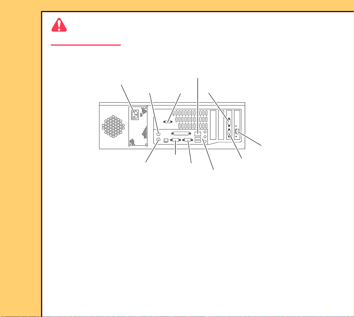
10 De-energize the CR 500 SYSTEM.
INTERNAL
NETWORK
POWER
MOUSE
COM 2
COM 3
CUSTOMER NETWORK
KEYBOARD
COM 1
MONITOR
MOTHER BOARD
COM 4
H195_1195BCA
H195_1195BC
Page 53

06DEC05
AR4366-1
Page
53 of 219
ADJUSTMENTS AND REPLACEMENTS Replacements
Important
On computers with 2 COM PORTS on the MOTHER BOARD, COM 1 is next to the
MONITOR CONNECTOR.
11 Label and then disconnect the following CABLES:
CABLE From 2.4 GHz Computer From 3.0 GHz Computer
UPS CABLE COM 1 COM 1
HOSPITAL NETWORK CABLE CUSTOMER NETWORK CUSTOMER NETWORK
INTERNAL NETWORK CABLE INTERNAL NETWORK INTERNAL NETWORK
MONITOR CABLE MONITOR MONITOR
MOUSE CABLE MOUSE MOUSE
KEYBOARD CABLE KEYBOARD KEYBOARD
POWER POWER POWER
MODEM - optional COM 2 COM 4
BAR CODE READER - optional KEYBOARD
COM 3
KEYBOARD
COM 3
Page 54

06DEC05
AR4366-1
Page
54 of 219
ADJUSTMENTS AND REPLACEMENTS Replacements
CPU
H195_0016BCA
H195_0016BC
12 Remove the CPU.
To Install:
Important
You must use a TORQUE WRENCH TL-1537 to tighten all Torx SCREWS to:
• 12 in./lb for T-10 size Torx SCREWS
• 21 in./lb for T- 20 size Torx SCREWS
1 Reverse the steps in the removal procedure.
Page 55

ADJUSTMENTS AND REPLACEMENTS Replacements
06DEC05
AR4366-1
Page
55 of 219
Postrequisites:
1 Restore all customer configurations. See:
Publication Procedure
• For system software version 4.10 - SOFTWARE
INSTRUCTIONS for the RECOVERY KIT V4 .1
SI3519-8
• For system software version 3.6 - SOFTWARE
INSTRUCTIONS for the RECOVERY KIT V3 .6
SI4366-1
Restoring the Parameters
Page 56

06DEC05
AR4366-1
Page
56 of 219
ADJUSTMENTS AND REPLACEMENTS Replacements
HARD DRIVE
Prerequisites:
1 None.
To Remove:
1 Indicate to the customer that all images will be erased.
Important
For systems with software version ≥ 4.1, you must have a “Session ID” for access to “Service
Functions” and “Diagnostics”. See SERVICE BULLETIN 843.
2 At the main menu, click:
• [Service Functions]
• [Network Configuration]
Page 57

06DEC05
AR4366-1
Page
57 of 219
ADJUSTMENTS AND REPLACEMENTS Replacements
Page 58

ADJUSTMENTS AND REPLACEMENTS Replacements
06DEC05
AR4366-1
Page
58 of 219
3 Record:
• “Local IP Address” __________________________________________
• “Computer Station Name” ______________________________________________
• “Subnet Mask” _____________________________________________
• “Default Gateway” ______________________________________
• “RAS IP Address Range” ______________________________________
• “Network Speed/Duplex” ______________________________________
4 Click [MAIN MENU].
5 If necessary, for access to the HIS/RIS information, click:
• [Key Operator Functions]
• [System Configuration]
• [HIS/RIS - Broker Configuration]
• [Polling Configuration]
6 Record the HIS/RIS information:
• “PACS Broker AE Title”
• “PACS Broker IP Address”
• “PACS Broker Port”
• “PACS Broker Modality”
• “Station Name/AE Title(s)”
7 Record the selected parameters check boxes.
8 Insert the USER PREFERENCE DISKETTE stored at the customer site.
9 At the main menu, click:
• [Key Operator Functions]
• [System Configuration]
Page 59

06DEC05
AR4366-1
Page
59 of 219
ADJUSTMENTS AND REPLACEMENTS Replacements
10 Click [SAVE ALL CONFIGS].
11 Remove the USER PREFERENCE DISKETTE.
12 Click [MAIN MENU].
Caution
Dangerous Voltage
13 De-energize the CR 500 SYSTEM.
14 Remove the CPU.
Page 60

06DEC05
AR4366-1
Page
60 of 219
ADJUSTMENTS AND REPLACEMENTS Replacements
2 BUTTONS
2 BUTTONS
CPU COVER
ESD
Possible damage from electrostatic discharge.
CPU COVER
15 Press the 2 BUTTONS on the CPU
COVER and remove it.
H195_1092ACA
H195_1092ACA
H195_1092AC
CPU
CPU
H195_1092AC
Page 61

06DEC05
AR4366-1
Page
61 of 219
ADJUSTMENTS AND REPLACEMENTS Replacements
4 SCREWS
HARD DRIVE
2 SCREWS
CPU
16 Remove:
• 2 SCREWS
• HARD DRIVE BRACKET
17 Disconnect:
HARD DRIVE
BRACKET
POWER
CABLE
RIBBON
CABLE
H177_0704HCA
H177_0704HC
• RIBBON CABLE
• POWER CABLE
18 Remove:
• 4 SCREWS - keep
• HARD DRIVE - discard
Page 62

06DEC05
AR4366-1
Page
62 of 219
ADJUSTMENTS AND REPLACEMENTS Replacements
CONNECTOR J26
H177_0708HCA
H177_0708HC
19 Check that the CONNECTOR J26 is seated correctly.
Note
If CONNECTOR J26 is not seated correctly, you might receive the following message: “1962
No operating system found”. “Press F1 to start boot sequence”.
Page 63

ADJUSTMENTS AND REPLACEMENTS Replacements
06DEC05
AR4366-1
Page
63 of 219
To Install:
Important
You must use a TORQUE WRENCH TL-1537 to tighten all Torx SCREWS to:
• 12 in./lb for T-10 size Torx SCREWS
• 21 in./lb for T- 20 size Torx SCREWS
4 SCREWS
2 SCREWS
HARD DRIVE
BRACKET
CPU
POWER
CABLE
RIBBON
CABLE
HARD DRIVE
1 Install the new HARD DRIVE with the existing 4 SCREWS.
H177_0704HCA
H177_0704HC
Page 64

ADJUSTMENTS AND REPLACEMENTS Replacements
06DEC05
AR4366-1
Page
64 of 219
2 Install:
• RIBBON CABLE
• POWER CABLE
• HARD DRIVE BRACKET
• 2 SCREWS
3 Install:
• CPU COVER
CPU COVER
• CPU
CPU
H195_1092ACB
H195_1092AC
Caution
Dangerous Voltage
4 Energize the CR 500 SYSTEM.
5 Wait until the main menu displays.
6 Insert the USER PREFERENCES DISK stored at the customer site.
Page 65

ADJUSTMENTS AND REPLACEMENTS Replacements
06DEC05
AR4366-1
Page
65 of 219
Postrequisites:
1 Restore all customer configurations. See:
Publication Procedure
• For system software version 4.10 - SOFTWARE
INSTRUCTIONS for the RECOVERY KIT V4 .1
SI3519-8
• For system software version 3.6 - SOFTWARE
INSTRUCTIONS for the RECOVERY KIT V3 .6
SI4366-1
Restoring the Parameters
Page 66

06DEC05
AR4366-1
Page
66 of 219
ADJUSTMENTS AND REPLACEMENTS Replacements
EXTRACTION PIN
Prerequisites:
1 Remove:
• FRONT COVER
• TOP COVER
To Remove:
Caution
Dangerous Voltage
1 Remove:
LEFT SIDE
PANEL
FRONT PANEL
4 SCREWS
6 SCREWS
H195_1022ACB
H195_1022AC
• 6 SCREWS
• FRONT PANEL
• 4 SCREWS
• LEFT SIDE PANEL
Page 67

06DEC05
H195_1025BC
SPRING
EXTRACTION PIN
H195_1025BCA
EXTRACTION PIN
SPRING
H195_1025BC
SPRING
EXTRACTION PIN
H195_1025BCA
EXTRACTION PIN
SPRING
AR4366-1
Page
67 of 219
ADJUSTMENTS AND REPLACEMENTS Replacements
Important
Do not allow the SPRING to fall.
2 Disengage the SPRING.
3 Remove the EXTRACTION PIN.
To Install:
Important
You must use a TORQUE WRENCH TL-1537 to tighten all Torx SCREWS to:
• 12 in./lb for T-10 size Torx SCREWS
• 21 in./lb for T- 20 size Torx SCREWS
1 Reverse the steps in the removal procedure.
Postrequisites:
None
Page 68

06DEC05
AR4366-1
Page
68 of 219
ADJUSTMENTS AND REPLACEMENTS Replacements
S1/S4 and S12/S13 SENSOR BOARDS - DETECTOR
Prerequisites:
1 Remove:
• FRONT COVER
• TOP COVER
To Remove:
1 Disconnect the CONNECTOR.
2 Remove:
• 2 SCREWS
S1/S4 LEFT
DETECTOR
SENSOR BD
S12/S13 RIGHT
DETECTOR
SENSOR BD
CONNECTOR
CONNECTOR
2 SCREWS
2 SCREWS
H195_1062HCA
H195_1062HC
• if necessary, S1/S4 LEFT DETECTOR SENSOR BOARD
• if necessary, S12/S13 RIGHT DETECTOR SENSOR BOARD
Page 69

ADJUSTMENTS AND REPLACEMENTS Replacements
06DEC05
AR4366-1
Page
69 of 219
To Install:
Important
You must use a TORQUE WRENCH TL-1537 to tighten all Torx SCREWS to:
• 12 in./lb for T-10 size Torx SCREWS
• 21 in./lb for T- 20 size Torx SCREWS
1 Reverse the steps in the removal procedure.
Postrequisites:
None
Page 70

06DEC05
AR4366-1
Page
70 of 219
ADJUSTMENTS AND REPLACEMENTS Replacements
S1/S4 and S12/S13 SENSOR BOARDS - EMITTER
Prerequisites:
1 Remove the CASSETTE INTERFACE AY:
To Remove:
Caution
The weight of the CASSETTE INTERFACE
CASSETTE
INTERFACE AY
AY is 13 kg (29 lb).
1 Place the CASSETTE INTERFACE AY
on a flat surface.
2 Disconnect the CONNECTOR.
3 Remove:
• 2 SCREWS
• if necessary, S1/S4 LEFT EMITTER
SENSOR BOARD
S12/S13 RIGHT
EMITTER SENSOR
BOARD
2 SCREWS
S1/S4 LEFT
H195_1027GCA
H195_1027GC
EMITTER SENSOR
BOARD
CONNECTOR
• if necessary, S12/S13 RIGHT
EMITTER SENSOR BOARD
To Install:
Important
You must use a TORQUE WRENCH TL-1537 to tighten all Torx SCREWS to:
• 12 in./lb for T-10 size Torx SCREWS
Page 71

ADJUSTMENTS AND REPLACEMENTS Replacements
06DEC05
AR4366-1
Page
71 of 219
• 21 in./lb for T- 20 size Torx SCREWS
1 Reverse the steps in the removal procedure.
Postrequisites:
None
Page 72

06DEC05
AR4366-1
Page
72 of 219
ADJUSTMENTS AND REPLACEMENTS Replacements
CASSETTE INTERFACE AY
Prerequisites:
1 Remove:
• FRONT COVER
• TOP COVER
To Remove:
Caution
Dangerous Voltage
1 De-energize the system.
NETWORK CABLE
2 Remove:
• 6 SCREWS
• FRONT PANEL
FRONT PANEL
6 SCREWS
POWER
CABLE
H195_1110HCA
H195_1110HC
Page 73

06DEC05
AR4366-1
Page
73 of 219
ADJUSTMENTS AND REPLACEMENTS Replacements
2 CASSETTE
GUIDES
Important
You must move the 2 CASSETTE GUIDES
to the center position to prevent damage to
center
position
LIGHT
LOCK
SEALS
the LIGHT LOCK SEALS.
3 Move the 2 CASSETTE GUIDES to the
center position of the CASSETTE
INTERFACE AY.
4 Fasten the WIRE TIE to the 2
CASSETTE GUIDES.
CASSETTE
INTERFACE AY
center
position
WIRE TIE
H195_1118ACB
H195_1118AC
CLIP
CONNECTOR A1J10
CONNECTOR A1P2
CONNECTOR A1P1
CASSETTE
INTERFACE AY
SCREW
CASSETTE
GUIDES
2 SCREWS
LIGHT LOCK
SEALS
H195_1109HCA
H195_1109HC
Page 74

ADJUSTMENTS AND REPLACEMENTS Replacements
06DEC05
AR4366-1
Page
74 of 219
5 Disconnect the CONNECTORS:
• A1P1
• A1P2
• A1J10
6 Remove:
• SCREW
• CLIP
Caution
• The weight of the CASSETTE INTERFACE AY is 13 kg (29 lb).
• Prevent damage to the LIGHT LOCK SEALS.
• The CASSETTE GUIDES must be in the center position
7 Remove:
• 2 SCREWS
• CASSETTE INTERFACE AY
8 Place the CASSETTE INTERFACE AY on a flat surface.
To Install:
Important
You must use a TORQUE WRENCH TL-1537 to tighten all Torx SCREWS to:
• 12 in./lb for T-10 size Torx SCREWS
• 21 in./lb for T- 20 size Torx SCREWS
1 Reverse the steps in the removal procedure.
Postrequisites:
None
Page 75

06DEC05
AR4366-1
Page
75 of 219
ADJUSTMENTS AND REPLACEMENTS Replacements
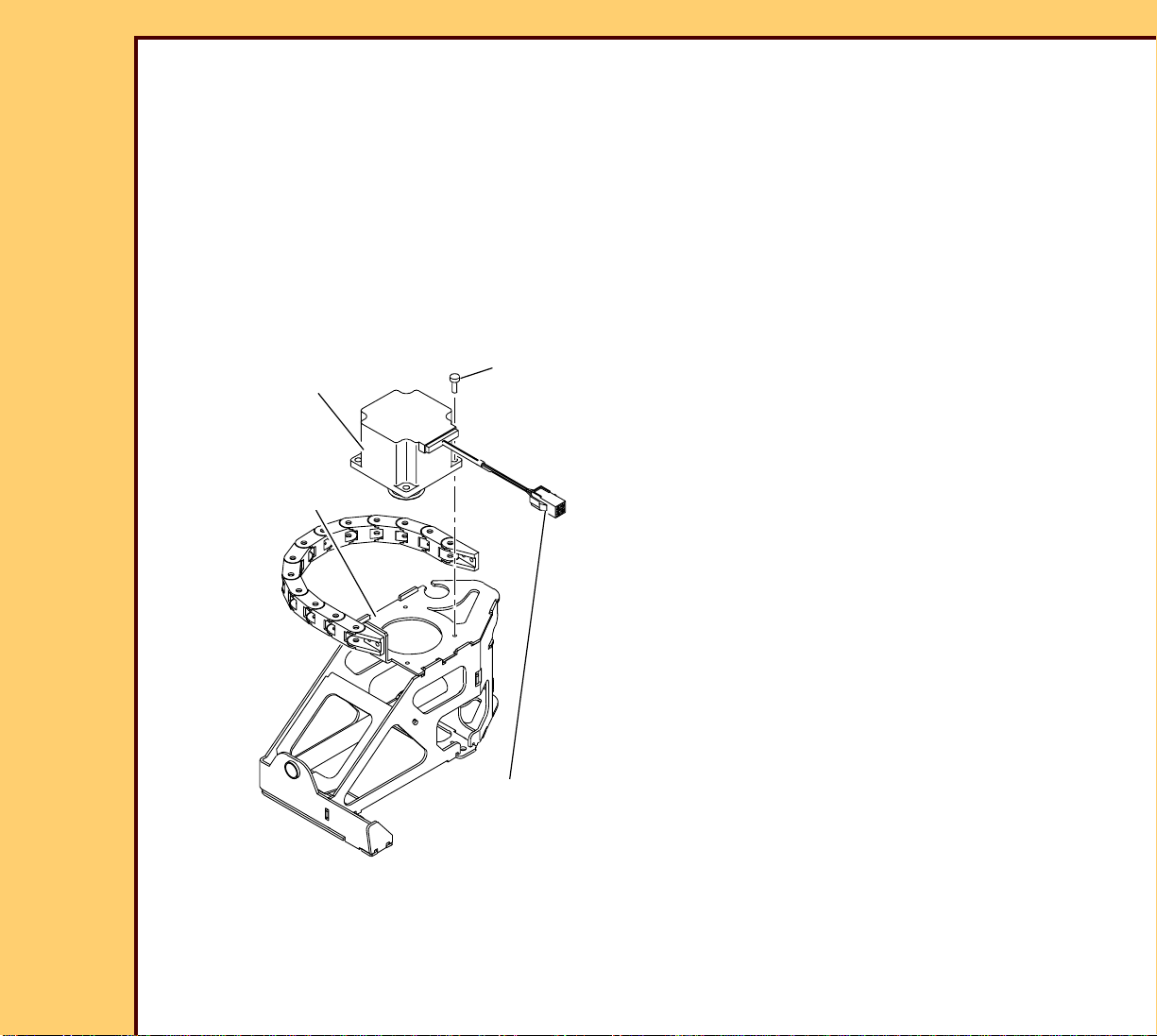
GUIDE MOTOR
Prerequisites:
1 Remove the CASSETTE INTERFACE AY.
To Remove:
Important
You might have to cut the WIRE TIE to install the TOOL 6F9611.
CASSETTE
INTERFACE AY
C-CLAMP
TOOL
CASSETTE
GUIDES
WIRE TIE
H195_1174ACA
1 If necessary, cut the WIRE TIE.
2 Install:
• TOOL 6F9611 on to the CASSETTE
GUIDES
• C-CLAMP on to the TOOL and the
CASSETTE INTERFACE AY
H195_1174AC
Page 76

06DEC05
AR4366-1
Page
76 of 219
ADJUSTMENTS AND REPLACEMENTS Replacements
4 NUTS
GUIDE MOTOR
3 Remove the 4 NUTS.
4 Disconnect:
CONNECTOR
ground wire
H195_1028GCA
H195_1028GC
To Install:
• CONNECTOR
• ground wire
5 Remove the GUIDE MOTOR.
Important
You must use a TORQUE WRENCH TL-1537 to tighten all Torx SCREWS to:
• 12 in./lb for T-10 size Torx SCREWS
• 21 in./lb for T- 20 size Torx SCREWS
1 Reverse the steps in the removal procedure.
Postrequisites:
None
Page 77

06DEC05
AR4366-1
Page
77 of 219
ADJUSTMENTS AND REPLACEMENTS Replacements
M9 LEFT CASSETTE CLAMP MOTOR
Prerequisites:
1 Remove:
• FRONT COVER
• TOP COVER
• CASSETTE INTERFACE AY
To Remove:
Important
The CASSETTE GUIDES must be:
• moved to the center of the CASSETTE INTERFACE AY
• fastened with WIRE TIES
Page 78

06DEC05
AR4366-1
Page
78 of 219
ADJUSTMENTS AND REPLACEMENTS Replacements
4 SCREWS
CONNECTOR M9J1
LEFT CASSETTE
CLAMP MOTOR
ground wire
1 Disconnect:
• CONNECTOR M9J1
• ground wire
2 Remove the 4 SCREWS.
3 Remove the LEFT CASSETTE CLAMP MOTOR.
H195_1063HCD
H195_1063HC
Page 79

ADJUSTMENTS AND REPLACEMENTS Replacements
06DEC05
AR4366-1
Page
79 of 219
To Install:
Important
You must use a TORQUE WRENCH TL-1537 to tighten all Torx SCREWS to:
• 12 in./lb for T-10 size Torx SCREWS
• 21 in./lb for T- 20 size Torx SCREWS
1 Reverse the steps in the removal procedure.
Postrequisites:
None
Page 80

06DEC05
AR4366-1
Page
80 of 219
ADJUSTMENTS AND REPLACEMENTS Replacements
M3 FEED DRIVE MOTOR
Prerequisites:
1 Remove the CASSETTE INTERFACE AY.
To Remove:
Important
The CASSETTE GUIDES must be:
• moved to the center of the CASSETTE INTERFACE AY
• fastened with WIRE TIES
Page 81

06DEC05
AR4366-1
Page
81 of 219
ADJUSTMENTS AND REPLACEMENTS Replacements
4 SCREWS
CONNECTOR M3J1
FEED DRIVE
MOTOR
1 Disconnect the CONNECTOR M3J1.
2 Remove:
• 4 SCREWS
• FEED DRIVE MOTOR
H195_1063HCE
H195_1063HC
Page 82

ADJUSTMENTS AND REPLACEMENTS Replacements
06DEC05
AR4366-1
Page
82 of 219
To Install:
Important
You must use a TORQUE WRENCH TL-1537 to tighten all Torx SCREWS to:
• 12 in./lb for T-10 size Torx SCREWS
• 21 in./lb for T- 20 size Torx SCREWS
1 Reverse the steps in the removal procedure.
Postrequisites:
None
Page 83

06DEC05
AR4366-1
Page
83 of 219
ADJUSTMENTS AND REPLACEMENTS Replacements
LEFT CARRIAGE AY
Prerequisites:
1 Remove the M3 FEED DRIVE MOTOR.
To Remove:
RIGHT CARRIAGE AY
2 SCREWS
CASSETTE
INTERFACE AY
1 Remove:
• 2 SCREWS
• RIGHT CARRIAGE AY
H195_1182GCA
H195_1182GC
Page 84

ADJUSTMENTS AND REPLACEMENTS Replacements
06DEC05
AR4366-1
Page
84 of 219
To Install:
Important
You must use a TORQUE WRENCH TL-1537 to tighten all Torx SCREWS to:
• 12 in./lb for T-10 size Torx SCREWS
• 21 in./lb for T- 20 size Torx SCREWS
1 Reverse the steps in the removal procedure.
Postrequisites:
None
Page 85

06DEC05
H195_1117HC
BRACKET
SHAFT
DRIVE BELT
LEFT CASSETTE
BEARING
CLAMP AY
E-RING
H195_1117HCA
WASHER
AR4366-1
Page
85 of 219
ADJUSTMENTS AND REPLACEMENTS Replacements
LEFT CASSETTE CLAMP DRIVE BELT
Prerequisites:
1 Remove:
• M9 LEFT CASSETTE CLAMP MOTOR
• M3 FEED DRIVE MOTOR
• LEFT CARRIAGE AY
To Remove:
1 Move the BEARING down the SHAFT from the BRACKET.
Page 86

ADJUSTMENTS AND REPLACEMENTS Replacements
06DEC05
AR4366-1
Page
86 of 219
2 Remove:
• E-RING
• WASHER
• CLAMP AY
• LEFT CASSETTE CLAMP DRIVE BELT
To Install:
Important
You must use a TORQUE WRENCH TL-1537 to tighten all Torx SCREWS to:
• 12 in./lb for T-10 size Torx SCREWS
• 21 in./lb for T- 20 size Torx SCREWS
1 Reverse the steps in the removal procedure.
Postrequisites:
None
Page 87

06DEC05
AR4366-1
Page
87 of 219
ADJUSTMENTS AND REPLACEMENTS Replacements
M2 PIN EXTRACT MOTOR
Prerequisites:
1 Remove:
• FRONT COVER
• TOP COVER
• LEFT CARRIAGE AY
To Remove:
1 Disconnect the CONNECTOR M2J1.
4 SCREWS
2 Remove:
• SPRING
• 4 SCREWS
• M2 PIN EXTRACT MOTOR
ground wire
CONNECTOR M2J1
H195_1065GCA
H195_1065GC
SPRING
M2 PIN
EXTRACTION
MOTOR
Page 88

ADJUSTMENTS AND REPLACEMENTS Replacements
06DEC05
AR4366-1
Page
88 of 219
To Install:
Important
You must use a TORQUE WRENCH TL-1537 to tighten all Torx SCREWS to:
• 12 in./lb for T-10 size Torx SCREWS
• 21 in./lb for T- 20 size Torx SCREWS
1 Reverse the steps in the removal procedure.
Postrequisites:
None
Page 89
06DEC05
AR4366-1
Page
89 of 219
ADJUSTMENTS AND REPLACEMENTS Replacements
M10 RIGHT CLAMP MOTOR
Prerequisites:
1 Remove:
• FRONT COVER
• TOP COVER
• CASSETTE INTERFACE AY
To Remove:
M10 PIN
EXTRACTION MOTOR
RIGHT CARRIAGE AY
4 SCREWS
CONNECTOR M10J1
H195_1183GCA
H195_1183GC
1 Disconnect the CONNECTOR M10J1.
2 Remove from the RIGHT CARRIAGE
AY:
• 4 SCREWS
• M10 PIN EXTRACT MOTOR
Page 90

ADJUSTMENTS AND REPLACEMENTS Replacements
06DEC05
AR4366-1
Page
90 of 219
To Install:
Important
You must use a TORQUE WRENCH TL-1537 to tighten all Torx SCREWS to:
• 12 in./lb for T-10 size Torx SCREWS
• 21 in./lb for T- 20 size Torx SCREWS
1 Reverse the steps in the removal procedure.
Postrequisites:
None
Page 91

06DEC05
AR4366-1
Page
91 of 219
ADJUSTMENTS AND REPLACEMENTS Replacements
RIGHT CARRIAGE AY
Prerequisites:
1 Remove:
• FRONT COVER
• TOP COVER
• CASSETTE INTERFACE AY
To Remove:
RIGHT CARRIAGE AY
2 SCREWS
CASSETTE
INTERFACE AY
H195_1181GCA
H195_1181GC
1 Remove:
• 2 SCREWS
• RIGHT CARRIAGE AY
Page 92

ADJUSTMENTS AND REPLACEMENTS Replacements
06DEC05
AR4366-1
Page
92 of 219
To Install:
Important
You must use a TORQUE WRENCH TL-1537 to tighten all Torx SCREWS to:
• 12 in./lb for T-10 size Torx SCREWS
• 21 in./lb for T- 20 size Torx SCREWS
1 Reverse the steps in the removal procedure.
Postrequisites:
None
Page 93

06DEC05
AR4366-1
Page
93 of 219
ADJUSTMENTS AND REPLACEMENTS Replacements
S5 FEED SENSOR
Prerequisites:
1 Remove:
• FRONT COVER
• TOP COVER
To Remove:
1 Disconnect the CONNECTOR S5/J1.
SCREW
S5 FEED
SENSOR
2 Remove:
• SCREW
• S5 FEED SENSOR
CONNECTOR
S5/J1
H195_1114GCA
H195_1114GC
Page 94

ADJUSTMENTS AND REPLACEMENTS Replacements
06DEC05
AR4366-1
Page
94 of 219
To Install:
Important
You must use a TORQUE WRENCH TL-1537 to tighten all Torx SCREWS to:
• 12 in./lb for T-10 size Torx SCREWS
• 21 in./lb for T- 20 size Torx SCREWS
1 Reverse the steps in the removal procedure.
Postrequisites:
1 Do the adjustment procedure for the EXTRACTION PIN.
Page 95

06DEC05
AR4366-1
Page
95 of 219
ADJUSTMENTS AND REPLACEMENTS Replacements
S14 PIN EXTRACTION SENSOR
Prerequisites:
1 Remove:
• FRONT COVER
• TOP COVER
• CASSETTE INTERFACE AY
To Remove:
1 Cut the WIRE TIE.
WIRE TIE
H195_1118ACD
H195_1118AC
Page 96

06DEC05
AR4366-1
Page
96 of 219
ADJUSTMENTS AND REPLACEMENTS Replacements
2 Disconnect the CONNECTOR S14/J1.
3 Remove:
• SCREW
• S14 PIN EXTRACTION SENSOR
CONNECTOR
S14/J1
S14 PIN
EXTRACTION
SENSOR
SCREW
H195_1115GCA
H195_1115GC
Page 97

06DEC05
AR4366-1
Page
97 of 219
ADJUSTMENTS AND REPLACEMENTS Replacements
4 Move the 2 CASSETTE GUIDES to the
2 CASSETTE
GUIDES
center position of the CASSETTE
INTERFACE AY.
center
position
CASSETTE
INTERFACE AY
center
position
WIRE TIE
H195_1118ACC
H195_1118AC
CASSETTE GUIDES.
To Install:
Important
You must use a TORQUE WRENCH TL-1537 to tighten all Torx SCREWS to:
• 12 in./lb for T-10 size Torx SCREWS
• 21 in./lb for T- 20 size Torx SCREWS
5 Fasten the WIRE TIE to the 2
1 Install:
• S14 PIN EXTRACTION SENSOR
• SCREW
2 Tighten the SCREW to 21 in./lb.
3 Connect the CONNECTOR S14/J1.
Postrequisites:
1 Do the adjustment procedure for the EXTRACTION PIN.
Page 98

06DEC05
AR4366-1
Page
98 of 219
ADJUSTMENTS AND REPLACEMENTS Replacements
RP 1 PRESSURE ROLLER
Prerequisites:
1 Remove the SLOW SCAN AY.
To Remove:
RP 1 CAM
DRIVE BELT
2 BEARINGS
2 C-RINGS
1 Remove:
• RP 1 CAM DRIVE BELT
• TENSION SPRING
• 2 CABLES
• 2 C-RINGS
• 2 BEARINGS
• RP 1 IDLER ROLLER
RP 1 IDLER ROLLER
2 CABLES
TENSION SPRING
H195_1155HCA
H195_1155HC
Page 99

ADJUSTMENTS AND REPLACEMENTS Replacements
06DEC05
AR4366-1
Page
99 of 219
To Install:
Important
You must use a TORQUE WRENCH TL-1537 to tighten all Torx SCREWS to:
• 12 in./lb for T-10 size Torx SCREWS
• 21 in./lb for T- 20 size Torx SCREWS
1 If necessary, use EMERY CLOTH to remove any debris from the ends of the new RP 1
IDLER SHAFT.
2 Reverse the steps in the removal procedure.
Postrequisites:
1 Adjust:
• FOLD MIRROR
• COLLECTOR AY - Tilt
2 Do Setting the Calibration.
Page 100

06DEC05
AR4366-1
Page
100 of 219
ADJUSTMENTS AND REPLACEMENTS Replacements
RP 1 DRIVE ROLLER
Prerequisites:
1 Remove:
• ERASE AY
• SLOW SCAN AY
To Remove:
BELT
E-RING
H195_1157BCA
H195_1157BC
1 Remove:
• BELT
• E-RING
• TENSION SPRING
• 2 CABLES
2 CABLES
TENSION
SPRING
 Loading...