

Page 1
{SiteSpecifications}{Production}{HealthImaging}{ExternalAndInternal}
Publication No. 1F5928
Specifications
for the
KODAK DIRECTVIEW CR 500 System
28OCT03
HEALTH IMAGING
H195_0016BC
Confidential
Restricted Information
© Eastman Kodak Company, 2003
Page 2

PLEASE NOTE The information contained herein is based on the experience and knowledge relating to the
subject matter gained by Eastman Kodak Company prior to publication.
No patent license is granted by this information.
Eastman Kodak Company reserves the right to change this information without notice, and
makes no warranty, express or implied, with respect to this information. Kodak sh all not be liable
for any loss or damage, including consequential or special damages, resulting from any use of
this information, even if loss or damage is caused by Kodak’s negligence or other fault.
This equipment includes parts and assemblies sensitive to damage from electrostatic
discharge. Use caution to prevent damage during all service procedures.
Table of Contents
Description Page
Equipment Specifications. . . . . . . . . . . . . . . . . . . . . . . . . . . . . . . . . . . . . . . . . . . . . . . . . . 3
Introduction
Size and Weight
Health and Safety Compliance
Site Specifications
Clearances
Recommended Placement for the CR 500 System
Power Requirements
Environmental Requirements
System Configuration
Network Requirements
Accessories and Support Items
Remote Operations Panel
Remote Patient Data Entry Station for the CR 500 System
Bar Code Reader
Site Checklist
Glossary
. . . . . . . . . . . . . . . . . . . . . . . . . . . . . . . . . . . . . . . . . . . . . . . . . . . . . . . . . . . . . . . 22
. . . . . . . . . . . . . . . . . . . . . . . . . . . . . . . . . . . . . . . . . . . . . . . . . . . . . . . . 3
. . . . . . . . . . . . . . . . . . . . . . . . . . . . . . . . . . . . . . . . . . . . . . . . . . . . . 4
. . . . . . . . . . . . . . . . . . . . . . . . . . . . . . . . . . . . . . . . . . 7
. . . . . . . . . . . . . . . . . . . . . . . . . . . . . . . . . . . . . . . . . . . . . . . . . . . . . . . 8
. . . . . . . . . . . . . . . . . . . . . . . . . . . . . . . . . . . . . . . . . . . . . . . . . . . . . . . . 8
. . . . . . . . . . . . . . . . . . . . . . . . . . 9
. . . . . . . . . . . . . . . . . . . . . . . . . . . . . . . . . . . . . . . . . . . . . . . . . 10
. . . . . . . . . . . . . . . . . . . . . . . . . . . . . . . . . . . . . . . . . . . 11
. . . . . . . . . . . . . . . . . . . . . . . . . . . . . . . . . . . . . . . . . . . . . . . . . 12
. . . . . . . . . . . . . . . . . . . . . . . . . . . . . . . . . . . . . . . . . . . . . . . . 13
. . . . . . . . . . . . . . . . . . . . . . . . . . . . . . . . . . . . . . . . . . . . . 15
. . . . . . . . . . . . . . . . . . . . . . . . . . . . . . . . . . . . . . . . . . . . . 15
. . . . . . . . . . . . . . . . . . . . 17
. . . . . . . . . . . . . . . . . . . . . . . . . . . . . . . . . . . . . . . . . . . . . . . . . . . . 18
. . . . . . . . . . . . . . . . . . . . . . . . . . . . . . . . . . . . . . . . . . . . . . . . . . . . . . . . . . . 19
2 28OCT03 – 1F5928
Page 3

Equipment Specifications
Section 1: Equipment Specifications
Introduction
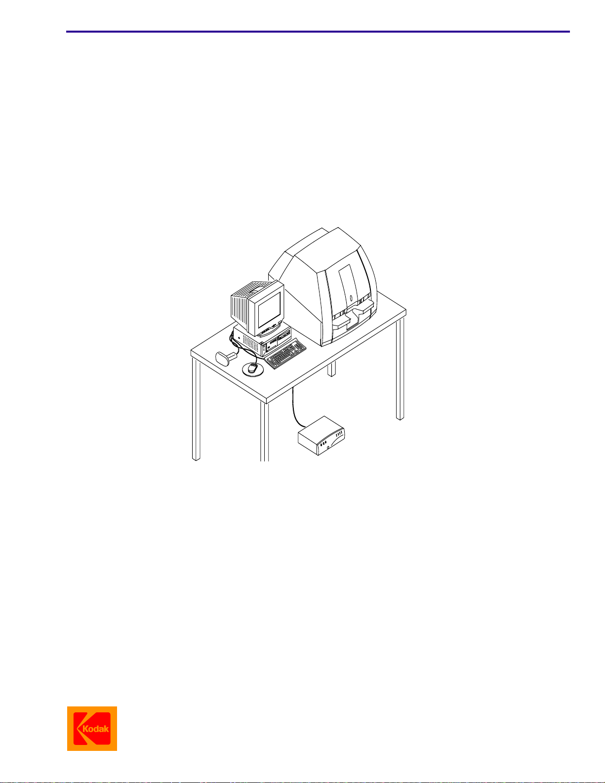
The KODAK DIRECTVIEW CR 500 System is a tabletop Computed Radiology (CR) System that lets you scan
exposed flexible storage phosphor screens, process the resulting images, and route these images to the ap propriate
destinations via a 10BaseT or 100BaseT Ethernet network. The system communicates with DICOM compatible
printers, CD/DVD storage, workstations and archives.
The KODAK DIRECTVIEW CR 500 System allows you to perform the following functions:
• Read images on a storage phosphor screen exposed by conventional X-ray generators.
• Enhance image processing.
• Enter examination and patient information using the KODAK DIRECTVIEW Remote Operations Panel (ROP),
the Bar Code Scanner, or the Keyboard.
• Correct erroneous information about the patient or examination.
• Store images that have incomplete patient or study data until the required data is added and the image is
accepted.
• Create collections of related images and data.
• Send exams to DICOM storage devices, physician’s diagnostic viewing stations, DICOM laser imagers, and
writable CD/DVD storage.
The KODAK DIRECTVIEW CR 500 System consists of:
• Personal Computer
• Keyboard
•Mouse
• CR 500 Storage Phosphor Reader
• KODAK DIRECTVIEW Software
• Uninterruptible Power Supply
The options for the KODAK DIRECTVIEW CR 500 System include:
• Flat Screen or CRT Monitor
• CD/DVD Writer
• External Bar Code Reader
• Isolation Transformer
• External Modem
• Flexible Storage Phosphor Screens
•KODAK DIRECTVIEW CR 500 Cassettes
The KODAK DIRECTVIEW CR Cassettes are standard size X-ray Cassettes which contain Storag e Phosphor
Screens. Exams are performed in the same manner a s with a conventional Film Casse tte. Instead of processing film
to develop the image, a Laser in the CR 500 System scans the latent image on the Phosphor Screen in the Cassette
and produces a digital image. Cassettes can be repeatedly exposed, erased and reused.
The CR 500 System accepts the following KODAK DIRECTVIEW CR Cassettes:
• 18 x 24 cm (7.1 x 9.4 in.)
• 15 x 30 cm (5.9 x 11.8 in.)
• 24 x 30 cm (9.4 x 11.8 in.)
• 35 x 35 cm (13.8 x 13.8 in.)
• 35 x 43 cm (13.8 x 16.9 in.)
1F5928 – 28OCT03 3
Page 4
SITE SPECIFICATIONS
Size and Weight
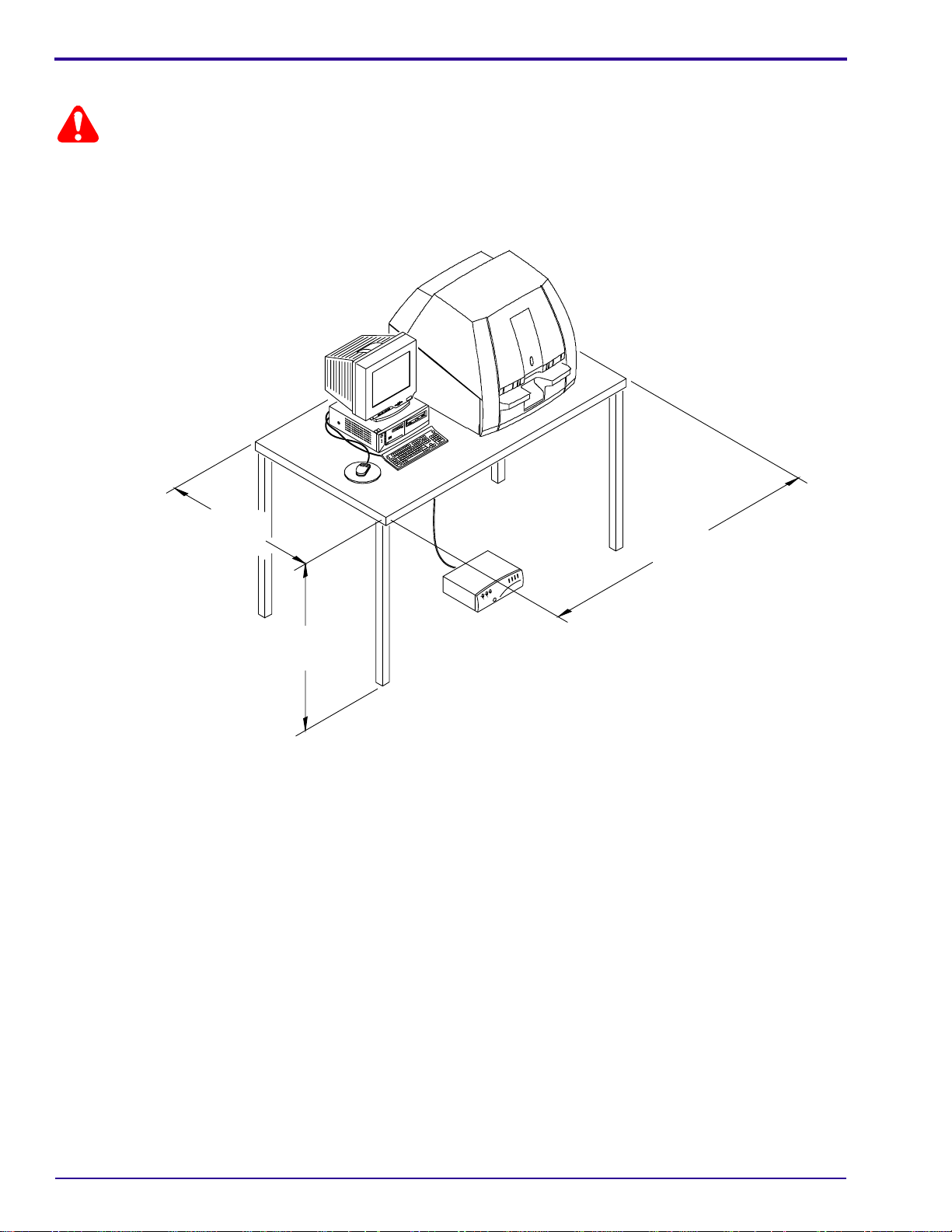
Warning
The customer must purchase a tabl e designed to support at least 136 kg (300 lbs) to support a single CR 500 System.
Place the CR 500 System on a level surface that is rigid and stron g enough to support t he weight of th e system an d
that is resistant to upset; for example, do not use a pedestal table.
Recommended Table Dimensions
76.2 cm
(30 in.)
152.4 cm
(60 in.)
76.2 cm
(30 in.)
H195_0016HC
4 28OCT03 – 1F5928
Page 5
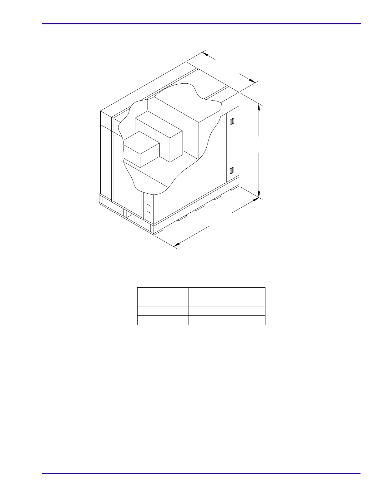
Dimensions of the Container for the CR 500 System
Equipment Specifications
88.9 cm
(35 in.)
106.7 cm
(42 in.)
H195_0063HC
175.3 cm
(69 in.)
Dimensions and Weight of the packed CR 500 System
Width 175.3 cm (69 in.)
Depth 88.9 cm (35 in.)
Height 106.7 cm (42 in.)
Weight 225.9 kg (498 lbs)
1F5928 – 28OCT03 5
Page 6
SITE SPECIFICATIONS
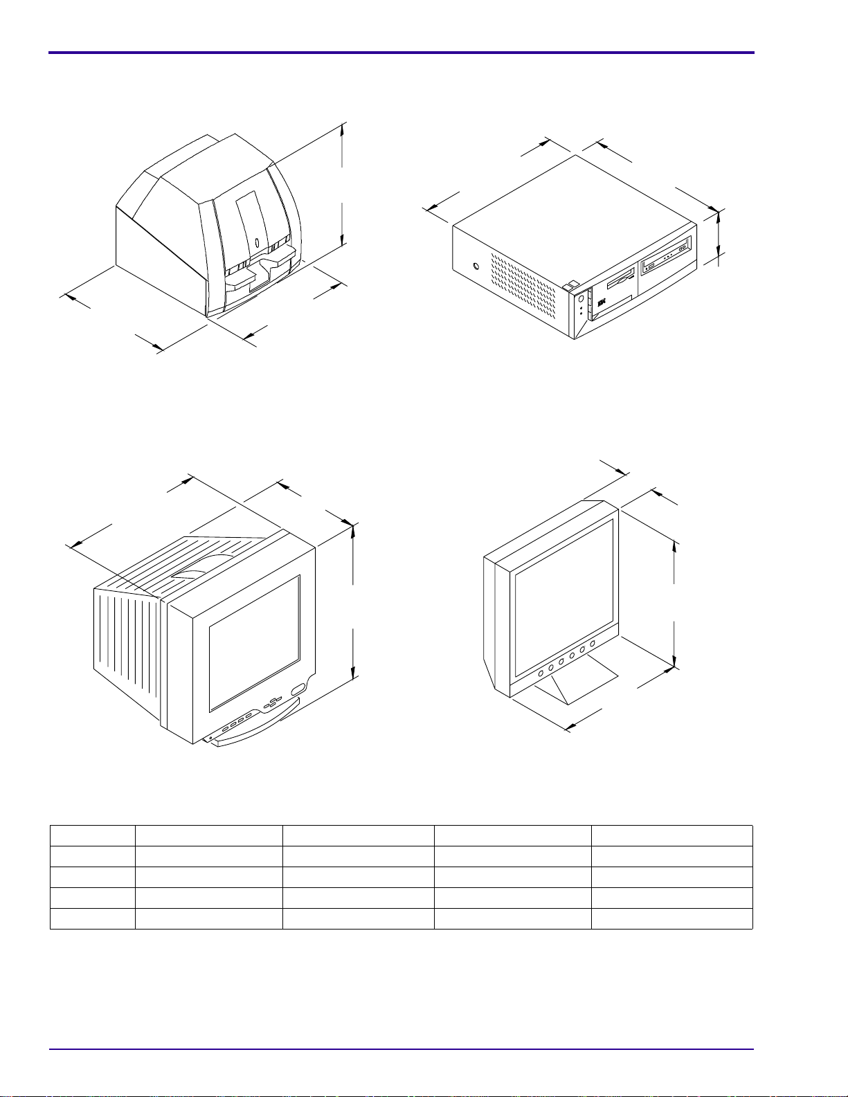
Reader
71.12 cm
(28 in.)
CRT Monitor
62.23 cm
(24.5 in.)
66.04 cm
(26 in.)
H195_0018AC
Computer
296.42 cm
(16.7 in.)
Flat Screen Monitor
296.42 cm
(16.7 in.)
13.97 cm
(5.5 in.)
H195_0021AC
40.39 cm
(15.9 in.)
42.42 cm
(16.7 in.)
42.67 cm
(16.8 in.)
38.1 cm
(15 in.)
38.1 cm
(15 in.)
H195_0019AC
Dimensions and Weight of the Reader, CRT Monitor, Flat Screen Monitor, and Computer
Reader Computer CRT Monitor Flat Screen Monitor
Width 62.23 cm (24.5 in.) 296.42 cm (16.7 in.) 40.39 cm (15.9 in.) 38.1 cm (15 in.)
Depth 71.12 cm (28 in.) 296.42 cm (16.7 in.) 42.67 cm (16.7 in.) 17.78 cm (7 in.)
Height 66.04 cm (26 in.) 13.97 cm (5.5 in.) 42.67 cm (16.8 in.) 38.1 cm (15 in.)
Weight 86.2 kg (190 lbs) 10 .4 kg (23 lbs) 15.0 kg (33 lbs) 4.9 kg (11 lbs)
17.78 cm
(7 in.)
H195_0020AC
6 28OCT03 – 1F5928
Page 7

Equipment Specifications
Health and Safety Compliance
The CR 500 System meets the following worldwide health and safety regulatory requirements:
• UL 60950
• CAN/CSA C22.2, No. 60950-00
• IEC 60601-1-1: Applies only to the CR 500 System equipped with the Isolation Transformer; See Page 10
• IEC 60825-1
• IEC 60950
• Title 21CFR Part 1040.10 and 1040.11 except for deviations pursuant to Laser Notice 50, dated 26 July 2003
• CE Mark
The CR 500 System meets the following Electromagnetic Capability (EMC) requirements:
Country Regulatory Requirements
United States FCC Emissions, Class A
Canada ICES-003 Issue 3 Class A ITE Emissions
Europe EN60601-1-2:1993 Medical Electrical Equipment Electromagnetic Compatibility
Emissions:
EN55011:1998 ISM Emissions, Group 1, Class A
.
Immunity:
• EN 61000-4-2/1995 ESD
• EN 61000-4-3/1997 Radiated RF Immunity
• EN 61000-4-4/1995 Electrical Fast Transient/Burst
• EN 61000-4-5/1995 Surge Immunity
• EN 61000-3-2/1995 Power Line Harmonics
• EN 61000-3-3/1995 Flicker
1F5928 – 28OCT03 7
Page 8

SITE SPECIFICATIONS
Section 2: Site Specifications
Clearances
Recommended Operating and Service Clearance
25.4 cm
(10 in.)
60.0 cm
(24 in.)
H195_0023GC
60.0 cm
(24 in.)
91.4 cm
(36 in.)
Important
• Operating:
– Allow 91.4 cm (36 in.) at the front of the CR 500 System.
–Do not place items on top of the CR 500 System.
• Servicing:
– Allow 60 cm (24 in.) at the sides, 91.4 cm (36 in.) at the front, 25.4 cm (10 in.) at the back.
– The areas around the sides and back of the CR 500 System must be cle ar f or access by ser vice pe rsonne l.
8 28OCT03 – 1F5928
Page 9

Recommended Placement for the CR 500 System
General Placement
The site layout will depend on the anticipated equipment configuration.
1.83 m
(6 ft)
2.5 m
(8 ft)
Site Specifications
1.83 m 1.83 m
(6 ft) (6 ft)
H174_0043GC
Warning
• This illustration indicates the patient vicinity according to the following regulatory requirements:
– UL 2601-1
– UL 60601-1
– IEC 60601-1
– IEC 60601-1-1
• Only the CR 500 Medical System, which is equipped with the Isolation Transformer, is recommended for use
within the patient vicinity.
• The customer must purchase a table designed to support at least 136 kg (300 lbs) to support a single CR 500
System. Place the CR 500 System on a level surface that is rigid and strong enough to support the weight of the
system and that is resistant to upset; for example, do not use a pedestal table.
1F5928 – 28OCT03 9
Page 10

SITE SPECIFICATIONS
Power Requirements
The KODAK DIRECTVIEW CR 500 System has an external Uninterruptible Power Supply (UPS).
The UPS provides continuous power and power line filtering to the CR 500 System. In the event of a power failure,
the UPS will provide power for the system to complete a scan in progress and execute a controlled shut-down. The
UPS also provides uninterrupted power during generator changeovers.
The CR 500 Medical System has an optional Isolation Transformer that accepts standard electrical power sources.
As a result, the CR 500 Medical System can be connected directly to existing power sources at most sites. The
Isolation Transformer isolates the electronics of the CR 500 Medical System and also provides internal
Electromagnetic Interference (EMI) f iltering and surge protection.
Important
• All electrical services, including earth ground, must comply with local and national electrical codes.
• Sites where the voltages are not in this range must use an I solation Transformer to obtain the correct voltage.
Power Requirements for the CR 500 System
Voltage: V AC Current: Amps Frequency: Hz
100 +
10% 5 50/60
115 +
10% 5 50/60
120 +
10% 5 50/60
127 + 6, −13% 5 50/60
200 +
10% 3 50/60
220 +
10% 3 50/60
230 +
10% 3 50/60
240 +
10% 3 50/60
Warning
• Never use extension cords.
• Never cut or remove the Ground Prong from the Power Cord.
• Failure to comply with these electrical specifications could void the customer’s warranty.
Four Power Cords are provided with the CR 500 System to allow connection to Receptacles at most sites: U.S.
Hospital Grade, Great Britain, Europe, and Japan.
10 28OCT03 – 1F5928
Page 11

Environmental Requirements
Temperature Operating: 15 to 30°C (59 to 86°F)
Storage, in package:
Relative Humidity Operating: 15 to 76%, noncondensing
Storage, in package: 5 to 86%, noncondensing
−23 to 66°C (−10 to 150°F)
Site Specifications
Altitude M aximum: 2438 m (8000 ft.) above sea level @ 30
Magnetic Field Operating: Outside of the 5 mT (50-gauss) line on the MRI fringe field plot for the site.
Servicing: Outside of the 0.5 mT (5-gauss) line on the MRI fringe field plot for the site.
Lighting For convenience and safety, all areas around the CR 500 System should be illuminated
with normal lighting of approximately 60 foot-candle (646 lux). Light levels may be as high
as 100 foot-candle (1076 lux) at the top surface.
Airflow The CR 500 System must have at least 25.4 cm (10 in.) clearance at the back to provide
adequate air flow.
Heat The CR 500 System produces 1477 kJ/hour (1400 Btu/hour) maximum.
Access See Page 8
.
°C (86°F) and 20% Relative Humidity
1F5928 – 28OCT03 11
Page 12

SITE SPECIFICATIONS
System Configuration
The KODAK DIRECTVIEW CR 500 System and optional KODAK DIRECTVIEW Remote Operations Panel can be
linked to a HIS/RIS and to a variety of destinations.
System Configuration
MITRA HIS/RIS
PACS Broker
Destinations
KODAK DIRECTVIEW
Remote Operations Panel
Archive System
CR 500 System
Remote Operations Panel
KODAK DIRECTVIEW
Workstation
KODAK PACS Link
9410 Acquisition System
KODAK DIRECTVIEW
Workstation
KODAK DRYVIEW
8100 Laser Imager
TM
CR 500 System
ETHERNET
H195_9000EC
12 28OCT03 – 1F5928
Page 13

Network Requirements
Cables and Connectors
Important
The following Cable and Connector must be provided by the customer for each CR 500 and for each
Remote Operations Panel:
Ethernet Network: 10/100BaseT
Cable Type: • Unshielded Twisted Pair, IEEE 802.3
Cable Length: 100 m (328 ft) maximum
Connector Type: Modular RJ-45
Modem and Telephone Line
Important
Do not use a digital telephone line, a telephone switching device, or a multi-line telephone system.
These systems might cause damage to the Modem.
• The telephone line must be a dedicated analog line.
• The RJ-11 Telephone Jack, or equivalent, must be within 2 m (6.6 ft.) of the CR 500 System.
For access to remote Kodak Service and Support, the CR 500 System must either have a Modem, or
be part of an installation that is connected to a Modem. See “
Page 15.
The customer is responsible for installing the telephone line.
Site Specifications
• Four pair (8 wire) 24 AWG gauge solid conductor
• One station per single twisted pair
• ANSI category 5 classification
Accessories and Support Items” on
HIS/RIS
HIS/RIS connections are available using, for example, the MITRA HIS/RIS PACS Broker.
Network Speed / Duplex
Important
The Network Setting of the CR 500 must match the Network Setting at the site. The CR 500 can be
configured to one of 5 settings:
• Auto Detect
• 10 Mbps / Half Duplex or 10 Mbps / Full Duplex
• 100 Mbps / Half Duplex or 100 Mbps / Full Duplex
IP Address
Each CR 500 System requires:
• One IP Address for the CR 500 System (Host Name)
• Two IP Addresses for the RAS Server connections if an optional Modem is installed
• Information for each destination:
– IP Address
– Logical Name (SCP AE Title)
– Film Type (for Printers)
1F5928 – 28OCT03 13
Page 14

SITE SPECIFICATIONS
The customer is responsible for completing the information in the following tables.
Customer Connectivity Matrix
Important
Device
Number Device Location
New/
Existing AE Title IP Address
1
2
3
4
5
Customer Connectivity Matrix (continued)
Device
Number Subnet Mask Gateway K Number
1
2
Port
Number
Service
Gateway Phone # Modem Phone #
Host
Name
Equipment
Serial #
3
4
5
Site Information
Site Name: Dial in # for Modem pool
Address Login Password
City/State/Province Admin Password
Customer Contact:
Phone #
Order #
Kodak AM: KMX #
Kodak Project Manager: KMX #
Kodak FE: KMX #
Kodak SM: KMX #
14 28OCT03 – 1F5928
Page 15

Accessories and Support Items
Section 3: Accessories and Support Items
Remote Operations Panel
The operator uses the optional KODAK DIRECTVIEW Remote Operations Panel, typically located near the site of
the imaging device, to enter the Cassett e ID and patient information int o the database. The informat ion is later added
to the image when the CR 500 System scans the cassette.
The operator can perform the following functions of the CR 500 System from a remote location:
• Enter examination and patient information manually or with the Bar Code Scanner.
• Correct erroneous information regarding patient or examination.
• Modify existing images and change the orientation.
• Send exams to DICOM devices.
The operator cannot scan images on a cassette using the Remote Operations Panel.
Remote Operations Panel
Remote Operations Panel: Size and Weight
Packaged Unpacked
Width 61.0 cm (24 in.) 48.3 cm (19 in.)
Depth 38.1 cm (15 in.) 12.7 cm (5 in.)
Height 61.0 cm (24 in.) 45.7 cm (18 in.)
Weight 10.9 kg (24 lb) 8.2 kg (18 lb)
177_0001AC
Wall Bracket
177_1505AC
Important
The customer is responsible for preparing the site for
the Remote Operations Panel and for installing the Wall
Bracket:
• Network Cables must be provided by the customer.
See Page 12
• The Remote Operations Panel must be mounted
on a wall at the eye level of the user.
• A minimum of 15.2 cm (6 in.) clearance is required
on each side of the Remote Operations Panel.
• The power source must be within 1.83 m (6 f t) of the
Remote Operations Panel.
• The wall must support 24.9 kg (55 lbs).
• The Temperature, Humidity, and Altitude
requirements are the same as for the CR 500.
• The CR 500 System must be correctly installed and
must be operating.
for examples of configurations.
1F5928 – 28OCT03 15
Page 16

SITE SPECIFICATIONS
Power Requirements:
The Remote Operations Panel has an Auto-Sensing Power Supply which allows the Panel to be connected directly
to existing power sources at most sites.
Remote Operations Panel: Power Requirements
Voltage: V AC Current: Amps Frequency: Hz
100 +
10% 3 50/60
115 +
10% 3 50/60
120 + 10, −13% 3 50/60
127 +
10% 3 50/60
200 +
10% 1.5 50/60
208 +
10% 1.5 50/60
220 +
10% 1.5 50/60
230 +
10% 1.5 50/60
240 +
10% 1.5 50/60
Note
All power is single phase. The voltages can be derived from a line and neutral or line-to-line connections.
Health and Safety Regulatory Requirements
The Remote Operations Panel meets the following worldwide health and safety regulatory requirements:
• UL 1950 Safety for Information Technology Equipment
• CSA No. 950 60950 Safety for Information Technology Equipment
• EN 60950: 1992 Safety for Information Technology Equipment (with Amendments A1, A2, A3, and A11)
EMC, Emissions, and Immunity Requirements
The Remote Operations Panel meets the following regulatory requirements:
Remote Operations Panel: EMC, Emissions, and Immunit y Requirements
Country Regulatory Requirements
United States FCC Emissions, Class A
Canada ICES-003 Issue 3, Class A
Europe Emissions: EN 55011:1998 ISM Emissions, Group 1 Class A
Immunity:
• EN 60601-1-2: 1993 Medical Electrical Equipment Electromagnetic Compatibility
• EN 61000-3-2: 1995 Power-line harmonics
• EN 61000-3-3: 1995 Flicker
• EN 61000-4-2: 1995 ESD
• EN 61000-4-3: 1997 RF immunity
• EN 61000-4-4: 1995 EFT
• EN 61000-4-5: 1995 Surge immunity
• EN 61000-4-6: 1996 Conducted immunity
• EN 61000-4-11: 1995 Voltage dips, sags, interrupts
16 28OCT03 – 1F5928
Page 17

Accessories and Support Items
Remote Patient Data Entry Station for the CR 500 System
The KODAK Remote Patient Data Entry Station (RPDES) is a software accessory that enables communication
between the customer supplied computer and the CR 500 System. This op tion allows up to 10 Remote Patient Data
Entry Stations into the database of the CR 500 System.
Important
• The site must not use the Dynamic Host Control Protocol (DHCP). The DHCP will change the IP Address of the
Remote Patient Data Entry Station or Remote Operations Panel (ROP) under the following conditions:
– Site system shutdown
– Site reboot
– Site license expiration
• The Remote Patient Data Entry Sta tion ca n b e co nf igu red u sin g one PC o r re pea ted wit h up to te n PCs f or o ne
CR 500 System.
Prerequisites
• The CR 500 System must be connected to the site network.
• The site must provide a Static IP Address for the Remote Patient Data Entry Station application.
• The PC must have INTERNET EXPLORER Version 6.0 or greater installed. The Operating System must be
WINDOWS 98 or greater.
• The Remote Patient Data Entry Station option must be loaded from a diskette and the option must be selected.
1F5928 – 28OCT03 17
Page 18

SITE SPECIFICATIONS
Bar Code Reader
The KODAK DIRECTVIEW CR 500 System can recognize Bar Codes of up to 36 characters.
The maximum width of the Bar Code is 13 cm (5.1 in.)
Prefix: zero to 10 characters
Data Field: Patient ID, one to 16 characters
Accession Number, one to 16 characters
Tech ID, one to 16 characters
Suffix: zero to 10 characters
Bar Code Type: Code 39, Code 128 and Interleafed 2 of 5
Descriptor: zero to 10 characters
The optional descriptor can be contained in the prefix, the suffix, or both.
The descriptor may be shorter in length than the prefix or the suffix.
18 28OCT03 – 1F5928
Page 19

Section 4: Site Checklist
Important
Installation cannot begin until the site is properly pr ep a red by the customer.
Field
System
Radiology
Technologist
Clearances and Weight
Power Requirements
Environmental Requirements
Administrator
Engineer
Item Responsibility Description√√ √
Dimensions Customer “
Weight Capacity Customer “Size and Weight” on Page 4
Clearances Customer • Operating: “Clearances” on Page 8
Electric Code
Compliance
Power
Requirements
Electrical Safety Customer • No extension cords ar e being used.
Power Cords Customer The correct power cords have been provided. “
Temperature Customer “
Relative Humidity Customer “Environmental Requirements” on Page 11
Altitude Customer “Env ironmental Requirements” on Page 11
Magnetic Field Customer “Environmental Requirements” on Page 11
Lighting Customer “Env ironmental Requirements ” on Page 11
Floor Surface Customer “Environmental Requirements” on Page 11
Airflow Customer “Environmental Requirements” on Page 11
Heat Output Customer “Environmental Requirements” on Page 11
Customer All electrical services, including earth ground, comply with
Customer “
Size and Weight” on Page 4
• Servicing: “Clearances” on Page 8
local and national electrical codes.
Power Requirements” on Page 10
• The Ground Prong has not been cut or removed from
the Power Cord.
Requirements” on Page 10
Environmental Requirements” on Page 11
Site Checklist
Power
1F5928 – 28OCT03 19
Page 20

SITE SPECIFICATIONS
Field
System
Radiology
Technologist
Engineer
Administrator
Item Responsibility Description√√ √
Remote Operations Panel
Dimensions Customer The site is prepared for the Panel: “
Clearance Customer “Remote Operations Panel” on Page 15
Wall Support Customer “Remote Operations Panel” on Page 15
Temperature Customer “Remote Operations Panel” on Page 15
Relative Humidity Customer “Remote Operations Panel” on Page 15
Altitude Customer “Remote Operations Panel” on Page 15
Wall Bracket Customer The Wall Bracket has been installed:
Power Source Customer The power source must be within 1.83 m (6 ft) of the
Power
Requirements
The CR 500
System
Remote Patient Data Entry Station
Requirements Customer “
Network Requirements
Cables and
Connectors
Cable Length Customer “Cables and Connectors” on Page 13
Connector Type Customer “Cables and Connectors” on Page 13
Telephone Line Customer “Modem and Telephone Line” on Page 13
HIS/RIS Customer A MITRA HIS/RIS PACS Broker, for example, is available.
IP Addresses Customer “IP Address” on Page 13
Network Speed /
Duplex
Connectivity Data Customer The customer must complete the information in the
Future Needs Customer Future needs have been considered.
Remote Operations
Panel” on Page 15
“
Remote Operations Panel” on Page15
Remote Operations Panel: “
Remote Operations Panel” on
Page 15
Customer “Remote Operations Panel: Power Requirements” on
Page 16
Customer The CR 500 must be correctly installed and operating.
Remote Patient Data Entry Station for the CR 500
System” on Page 17
Customer “Cables and Connectors” on Page 13
Customer The customer must provide the correct Network Setting
prior to installation. “
Tables: Page 14
Network Speed / Duplex” on Page 13
.
20 28OCT03 – 1F5928
Page 21

Site Checklist
Approval Signatures
I have completed the Site Checklist and agree that the site is ready to proceed with the installation of the CR 500
System.
__________________________________________________________________________________
Signature of Radiology Technologist
__________________________________________________________________________________
Signature of System Administrator
__________________________________________________________________________________
Signature of Field Engineer
1F5928 – 28OCT03 21
Page 22

Glossary
Section 5: Glossary
10/100BaseT A CSMA/CD Ethernet LAN using Twisted Pair with a baseband of either 10 Mbps or 100 Mbps.
The IEEE standard for 24-gauge UTP for Ethernet.
AE Application Entity
ANSI American National Standards Institute
AWG American Wire Gauge
CSMA/CD Carrier Sense Multiple Access / Collision Detection
DICOM The D
EIA Electrical Industries Association
Ethernet A passive coaxial cable that transmits digital signals for a network in which t he interconnections
contain active elements. A LAN standard that uses a bus topology with CSMA/CD access co ntrol.
HIS/RIS Hospital Information System / Radiology Information System
IP Internet Protocol
kVp Kilovoltage, peak
mAs Milliampere-seconds
Modem Modulator / Demodulator: A device that your computer uses to send data over telephone wires.
Mbps Mega bits per second
Protocol A set of rules allowing computers and peripherals to communicate with each other.
RAS Remote Access Service
RJ-11 A four-wire modular connector for telephone lines.
RJ-45 An eight-wire modular connector for Ethernet twisted-pair wiring.
TCP/IP Transfer Common Protocol / Internet Protocol: Set of communication protocols developed for
the Defense Advanced Research Projects Agency (DARPA) to connect dissimilar systems.
The TCP controls the transfer of the data, and the IP provides the routing mechanism.
Twisted Pair Wiring used in telephone systems and many networks, consisting of a pair of copper wires
twisted around each other to counteract the effe cts of noise. Commonly used instead of coaxial
Ethernet in network applications. Usually unshielded; however, the mor e expensive shielded
version supports greater distance with less risk of electrical interference.
UTP Unshielded Twisted Pair
igital Imaging and COmmunications in Medicine imaging standard.
Publication History
Publication
Date
28OCT03 1F5928 --- New 1f5928.fm First Printing
Printed in U.S.A. • 1f5928.fm
Publication
No. ECO No. Changed Pages File Name Notes
Kodak, DirectView, and DryView are trademarks of Eastman Kodak Company.
EASTMAN KODAK COMPANY
Rochester, NY 14650
HEALTH IMAGING
 Loading...