

Page 1
L
M
S
/
TAG
DISP/MENU
SELECT
W.BAL
L
A
I
O
AUTO
CARD
Camera Sides
AUTO
CARD
Strap
Attachment
Palm Door
IEEE 1394
Connection*
AC Adapter
Connection*
*Cover not shown
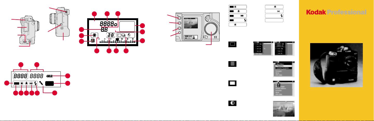
Back LCD Panel
2
3
4 5 7 8
6
1. Remaining Frames
2. Frame Number
3. White Balance
4. Auto
5. Daylight
6. Tungsten
Viewfinder
Dioptric
Adjustment
Dial
PC Terminal
(Cover) for
flash sync
(external)
1
7. Fluorescent
8. Flash
9. Battery Status Icon
10. PC Card Icon
11. Microphone Icon
Battery/PC
Card Door
11
Top LCD Panel
2
3
4
1. Shooting Modes—
2. Aperture Value or
9
10
3. Metering Modes (Partial;
4. Flash Exposure
5. AEB
6. Bulb Exposure Time;
7. Exposure Level Indicator;
1
13
V
M
T
D
EP
A
ISO
V
AEB
2
3 101
5 6 7 8
Manual Exposure: M
Shutter Priority AE: Tv
Bulb Exposure: bulb
Program AE: P
Aperture Priority: Av
Custom Function Control
or AEB Value or Depthof-Field AE
Evaluative; Fine Spot)
Compensation
Self-Timer Countdown
Bulb Exposure Time;
AEB Value Amount
12
ONE SHOT
AI SERVO
Indicator; Flash Exposure
Compensation Value
Indicator; Custom
Function Setting Indicator
8. Drive Mode Indicator
(Single Exposure;
Continuous Exposure;
Self-Timer—10 seconds,
2 seconds)
9. Exposure Compensation
Value Index
10. ISO Indicator
11. AF Mode Indicator
12. Focusing Points
13. Shutter Speed; ISO;
Battery Check (bc); Bulb
(bulb); Depth-of-Field AE
(dEP); Custom Function
Control
10
223
11
10
9
Using the Digital Controls
RECORD/
TAG Button
DISP/MENU
Button
SELECT Button
W.BAL Button
Quick Control Dial
Display the Menu bar and select a Menu bar icon: Press
and hold the DISP/MENU button and rotate the Quick Control
dial until the desired icon is highlighted.
Display a dropdown menu: Highlight the Folder, Menu, or
Display icon (see next page), and continue pressing the
DISP/MENU button until the dropdown menu appears.
Choose an item from a dropdown menu: Continue pressing
the DISP/MENU button and rotate the Quick Control dial
until the desired menu choice is highlighted.
Choose an item from a menu screen (e.g., Main menu):
Press and hold the SELECT button and rotate the Quick
Control dial to highlight your choice.
Tag an image: Quickly press and release the RECORD/TAG
button.
Record a sound file: Press and hold the RECORD/TAG
button and speak into the microphone.
Select a White Balance setting: Press and hold the W.BAL
button and rotate the Quick Control dial until the desired
White Balance icons appear in the Back LCD panel.
The Menu Bar
AUTO
AUTO
AUTO
AUTO
Auto - Daylight
Auto - Tungsten
Auto - Fluorescent
Auto - Flash
Daylight
Folder Icon
Displays
the Folder
menu
Menu Icon
Displays choices for the
Main, Properties, and
Custom Functions menus
Display Icon
Displays choices for Single,
Four, and Nine Image
Review mode
Contrast Icon
Displays the Display
Contrast screen where you
can adjust image contrast
Tungsten
Fluorescent
Flash
Custom
1 PC Card 2 PC Cards
DCS 500 Series
Digital Cameras
Page 2

Batteries
T o po wer y our camera,
open the Battery/PC
Card door, slide a
battery to the back of
the battery slot and
press firmly in place.
☛
You can also power your camera with an
AC adapter when working indoors or
connected to a computer.
Check the battery
icon on the Back
LCD panel.
Full
1/2 Full
Low
Empty
PC Card
As you capture images, they are stored on
Type II or T ype III PC Cards (PCMCIA cards)
in your camera.
There are two slots for PC Cards. You can
insert two Type II cards or one Type III card.
To insert a PC Card,
open the Battery/PC
Card door and insert.
With two cards, the first
card inserted is the
active card.
T o select a dif ferent PC
Card, select the Folder
icon, then select the
card. (Refer to the
other side.)
Important! Be sure the
Card Busy LED is off
before removing a PC
Card. The blinking
Eject
button
Card Busy LED
indicates data is being
transferred to or from
the PC Card. You can
lose data if you remove
a PC Card when it is busy.
To remove the PC Card, press the Eject
button.
Camera
Front
3
4
5
7
8
9
10
1. Lens Attachment Mark
2. Lens Mount
3. Shutter Button
4. Self-Timer Indicator
5. Palm Door (to access
6. Anti-aliasing or IR Filter
7. Depth-of-Field Preview
8. Vertical Control Switch
9. White Balance Sensor
2
1
(red)
Custom Functions)
Button
11
12
13
6
14
15
16
17
10. Canon Remote Port
11. X Contacts (for flash
attachments)
12. Lens Lock Pin
13. Strap Attachment
14. Lens Release Button
15. PC Terminal (Cover) for
flash sync (external)
16. Battery/PC Card Door (to
access battery and PC
Card)
17. Vertical Shutter Release
Camera
Back
1
2
3
6
DISP/MEN
U
7
8
9
1. Shooting Mode Selector
2. AF Mode Selector
3. Metering Mode Selector/
Flash Exposure
Compensation Button
4. Viewfinder Eyepiece
5. Image Display
6. RECORD/TAG Button
7. DISP/MENU Button
8. SELECT Button
9. W. BAL Button
4
/ TAG
5
SELEC
T
W.BAL
10
12
11
13
O
I
14
15
A
L
16
17
18
19
10. Back LCD Panel
11. Top LCD Panel
12. AE Lock Button
13. Focusing Point Selector
14. Quick Control Dial Switch
15. Palm Door
16. Quick Control Dial
17. Microphone
18. Main Switch
19. Vertical AE Lock Button
Camera Top
6 7 8
1
3
4
5
1. X Contacts
2. Accessory Shoe
3. Shooting Mode Selector
4. AF Mode Selector
5. Metering Mode Selector/
Kodak and Kodak Professional are trademarks.
Printed in U.S.A. P/N 6B5237 5/00
2
MODE
AF
ISO
6. LCD Panel Illumination
Button
7. Exposure Compensation
Button
Flash Exposure
Compensation Button
EASTMAN KODAK COMPANY
Rochester, New York 14650
© Eastman Kodak Company, 2000
8. Shutter Button
9. Main Dial
10. Top LCD Panel
9
10
 Loading...