

Page 1

Conversion Instructions
for the
Publication No. 9B8345
February 1997
Kodak Home Page
on Internet
Tech Bulletin
on Intranet
Kodak
AUTOMIXER III PLUS
Table of Contents
© Eastman Kodak Company
Page 2

PLEASE NOTE The information contained herein is based on the experience and knowledge relating to the
subject matter gained by Eastman Kodak Company prior to publication.
No patent license is granted by this information.
Eastman Kodak Company reserves the right to change this information without notice, and
makes no warranty, express or implied, with respect to this information. Kodak shall not be liable
for any loss or damage, including consequential or special damages, resulting from any use of
this information, even if loss or damage is caused by Kodak’s negligence or other fault.
Warning
To avoid hazardous conditions, keep floors and floor coverings around your
associated drains clean and dry at all times. Any accumulation of fluids from mixing tanks, drain lines, etc., should
be cleaned up immediately. In the event of an accumulation of liquid due to backup, overflow, orother malfunctions
of the drain associated withyour
with the drain.Kodak accepts noresponsibility or liabilitywhatsoever for theserviceability of anydrain connected to
or associated with a
Kodak X-Omat
Kodak X-Omat
Processor. Such drains are the sole responsibility of the customer.
Processor, call a plumber orothercontractor to correct any problem
Kodak X-Omat
Processors and
2 February 1997 – 9B8345
Page 3

Section 1: Parts
Purpose: To convert an AUTOMIXER III to an AUTOMIXER III PLUS
Table 1 Enhancement Kit 9B8668 includes:
Unitized
Description RA European RP
DEVELOPER BOTTLE TEMPLATE 8B6778 8B6769 8B6768 8B6761 1
FIXER BOTTLE TEMPLATE 8B6779 8B6766 8B6765 8B6763 1
DEVELOPER NEST 8B6764 8B6754 1
FIXER NEST 8B6767 8B6755 1
DEVELOPER DRAWER AY 8B6776 1
FIXER DRAWER AY 8B6777 1
KNIVES/COUPLING 8B6751 AR##AR = As Required.##
U-BRACKET 8B6771 1
BACK BRACKETS 8B6772 4
FRONT BRACKETS 8B6773 2
SUBMERSIBLE PUMP 8B6995 2
BRACKET 9B6799 2
MIX PUMP ADAPTER 9B8613 2
DEVELOPER FLOATING LID 9B8882 1
FIXER FLOATING LID 9B8883 1
WIRE TIE 182590 10
WIRE TIE MOUNT 264548 1
SCREWS 852682 12
Conversion Instructions 9B8345 1
RA/RP Qty
Parts
Table 2 Special Tools required:
Tool No. Description
TL-5131 COMPASS SAW
TL-1466 3/8 in. ELECTRIC DRILL
TL-4662 FILE
9B8345 – February 1997 3
Page 4
CONVERSION INSTRUCTIONS
Section 2: Installing the New DRAWERS
Removing the DRAWERS
[1] De-energize the PROCESSOR.
[2] Turn off the water supply.
[3] Disconnect the AUTOMIXER.
[4] Remove the FRONTPANEL. If necessary, seethe “Removing the Front Paneland 2 DRAWERS” procedure in
the Service Manual.
[5] Remove the 2 SIDE PANELS.
[6] DraintheREPLENISHMENTTANKS.Ifnecessary, see the “Draining the Replenishment Tank” procedure in the
Service Manual.
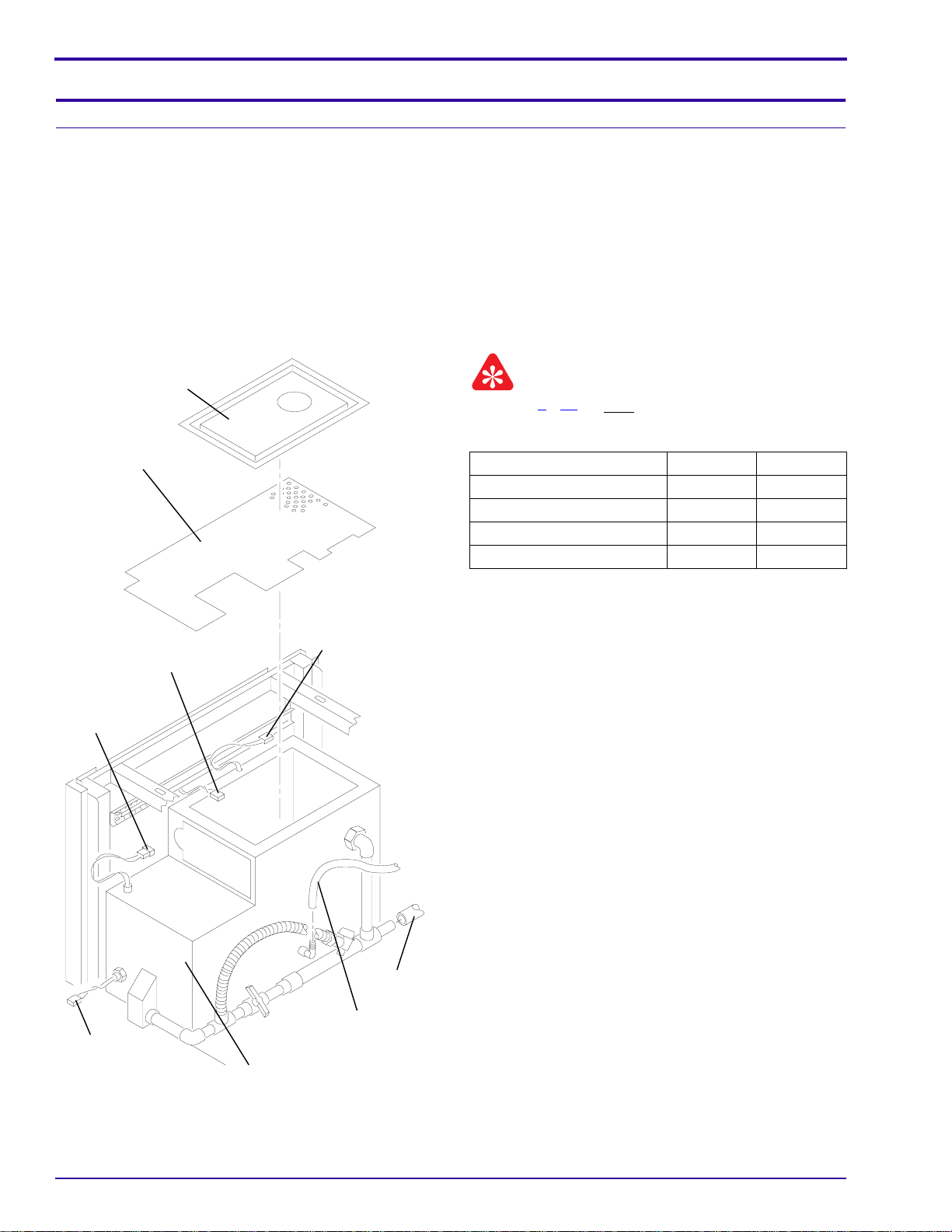
TANK
COVER
Do Steps 7 - 17 for both REPLENISHMENT TANKS.
Important
[7] Disconnect:
FLOATING
LID
MAGNETIC
SWITCH
CONNECTOR
LIQUID LEVEL
SWITCH
CONNECTOR
SUBMERSIBLE
PUMP
CONNECTOR
CONNECTOR Developer Fixer
FLOAT SWITCH P/J9 P/J3
LIQUID LEVEL SENSOR P/J10 P/J2
MAGNETIC SWITCH P/J11 P/J1
SUBMERSIBLE PUMP P/J12 P/J4
[8] Disconnect:
• DRAIN HOSE
• REPLENISHMENT HOSE
[9] Remove the REPLENISHMENT TANK. If
necessary,seethe“RemovingtheReplenishment
Tank” procedure in the Service Manual.
[10] Remove the TANK COVER and FLOATING LID.
[11] Rinse any debris from the bottom of the
REPLENISHMENT TANK.
DRAIN
HOSE
REPLENISHMENT
FLOAT SWITCH
CONNECTOR
H115_0062CCA
H115_0062CA
4 February 1997 – 9B8345
HOSE
REPLENISHMENT
TANK
Page 5
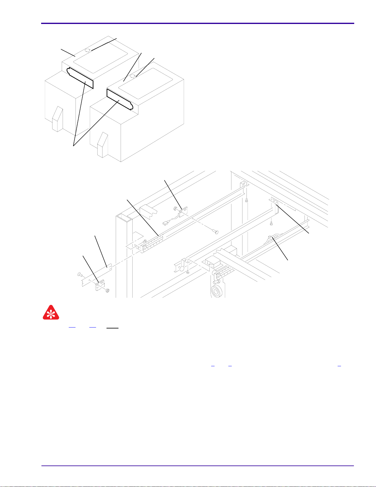
Installing the New DRAWERS
Developer
REPLENISHMENT
TANK
CUTOUT
H115_0058ACA
H115_0058AA
cut line
RAIL
Fixer
REPLENISHMENT
TANK
cut line
MAGNETIC
SWITCH
[12] Mark the newopening in the REPLENISHMENT
TANK. Use the CUTOUT on Page 11.
[13] Drill a hole at each of the 4 corners. Use 3/8 in.
ELECTRIC DRILL TL-1466.
[14] Cut the new opening in the REPLENISHMENT
TANK. Use COMPASS SAW TL-5131.
[15] Cut the CABLE hole larger. Follow the cut line.
Use COMPASS SAW TL-5131.
[16] Make the rough edges smooth. Use FILE TL-
4662.
[17] Remove any debris from the bottom of the
REPLENISHMENT TANK.
DRAWER
SLIDE
8 BRACKETS
MAGNET
WIRE
TIE
H115_0059BCA
H115_0059BA
Important
Do Steps 18 and 19 for both DRAWERS.
[18] Remove the MAGNET from the DRAWER SLIDE.
[19] Remove and keep the MAGNETIC SWITCH from the RAIL.
[20] Remove the WIRE TIE.
[21] Remove the 8 BRACKETS. Keep the fasteners for Steps 1 and 2 of “Installing the DRAWERS” on Page 6.
9B8345 – February 1997 5
Page 6

CONVERSION INSTRUCTIONS
Installing the DRAWERS
MAGNETIC
SWITCH
CONNECTOR
FRAME
2 front
BRACKETS
MAGNET
DRAWER
SLIDE
MAGNETIC
SWITCH
RAILS
4 back
BRACKETS
WIRE TIE MOUNT
H115_0060BCA
H115_0060BA
U-BRACKET
Caution
Do not compress the wires during the next step.
For the next 2 steps use the fasteners from Step 21 of “Removing the DRAWERS” on Page 5.
[1] Install the U-BRACKET onto the FRAME.
[2] Install the 2 front and 4 back BRACKETS onto the new RAILS.
[3] For each DRAWER, install the MAGNETIC SWITCH onto the RAIL.
[4] Install:
• RAILS
• new WIRE TIE MOUNT
[5] Place the wires on the MOUNT.
REPLENISHMENT
TANK
2 SCREWS
Do Steps 7 - 9 for both REPLENISHMENT TANKS.
2 NUTS
Important
[6] Remove:
• 2 NUTS
• 2 SCREWS
• BRACKET and SUBMERSIBLE PUMP
H115_0099ACA
H115_0099AA
6 February 1997 – 9B8345
Page 7

Installing the New DRAWERS
2 SCREWS
REPLENISHMENT
TANK
[7] Install:
• BRACKET
• 2 SCREWS
• SUBMERSIBLE PUMP
• 2 WIRE TIES
[8] Connectthe MIX PUMPADAPTER to the existing
CABLE and the new SUBMERSIBLE PUMP.
BRACKET
Caution
Theexcess CABLE and MIXPUMPADAPTER must be
3 WIRE TIES
on the outside of the TANK.
[9] Install a WIRE TIE on the excess CABLE and
place on the outside of the TANK.
H115_0097ACA
H115_0097AA
SUBMERSIBLE
PUMP
[10] Install the DRAWERS and check for correct operation. Adjust the RAILS, if necessary.
[11] Remove the DRAWERS.
9B8345 – February 1997 7
Page 8

CONVERSION INSTRUCTIONS
TANK
COVER
FLOATING
LID
MAGNETIC
SWITCH
CONNECTOR
LIQUID LEVEL
SWITCH
CONNECTOR
SUBMERSIBLE
PUMP
CONNECTOR
Important
Do Steps 12 - 16 for both REPLENISHMENT TANKS.
[12] Install:
• new FLOATING LID
• TANK COVER
• TANK
Note
If using the JUMPER option do not connect the
MAGNETIC SWITCH.
[13] Connect:
CONNECTOR Developer Fixer
FLOAT SWITCH P/J9 P/J3
LIQUID LEVEL SENSOR P/J10 P/J2
MAGNETIC SWITCH P/J11 P/J1
SUBMERSIBLE PUMP P/J12 P/J4
[14] Connect:
• DRAIN HOSE
• REPLENISHMENT HOSE
[15] Close the drain.
FLOAT SWITCH
CONNECTOR
H115_0062CCA
H115_0062CA
DRAIN
HOSE
REPLENISHMENT
HOSE
REPLENISHMENT
TANK
8 February 1997 – 9B8345
Page 9

Installing the New DRAWERS
RA Developer
RP Developer
European
BOTTLE,
Developer
UNITIZED
BOTTLE,
Developer
NEST
TEMPLATE
4 SCREWS
RA Fixer
RP Fixer
European
BOTTLE,
Fixer
UNITIZED
BOTTLE,
Fixer
n
Note
See the figure for the correct configuration of the DRAWERS.
[16] Install for each DRAWER:
• KNIVES
• NEST
• TEMPLATE
• 4 SCREWS
[17] Connect the AUTOMIXER.
[18] Install:
• 2 SIDE PANELS
• FRONT PANEL
• DRAWERS
[19] Turn on the water supply.
[20] Energize the PROCESSOR.
KNIVES
H115_0064HCA
H115_0064HA
9B8345 – February 1997 9
Page 10

CONVERSION INSTRUCTIONS
This page is intentionally blank.
10 February 1997 – 9B8345
Page 11

cut on dotted line
Installing the New DRAWERS
FIX
place cutout here
DEV
H115_0057ECA
H115_0057EA
9B8345 – February 1997 11
Page 12

CONVERSION INSTRUCTIONS
This page is intentionally blank.
12 February 1997 – 9B8345
Page 13

Publication History
Section 3: Publication History
Print Date Pub. No. ECO No. Affected Pages File Name Description
February 1997 9B8345 2504-453 All CI3402_1.doc First Printing
9B8345 – February 1997 13
Page 14

Kodak
is a trademark.
ci3402_1.fm
Printed In USA
Health Imaging
EASTMAN KODAK COMPANY ● ROCHESTER, N.Y. 14650
 Loading...