

Knight Equipment LUBE SAVER Installation Manual
Lube Saver System
Instruction Manual
0900929 Rev: REL (06/08) Page 1 of 12

TABLE OF CONTENTS
Specifications........................................................................................................ 3
Pre-Installation ......................................................................................................3
Installation............................................................................................................. 4
Operation .............................................................................................................. 5
Button Functions ...................................................................................................5
Programming ........................................................................................................6
Troubleshooting .................................................................................................... 9
Recommended Spare Parts.................................................................................. 9
Wiring Diagram ................................................................................................... 10
CAUTION: Wear protective clothing and eyewear when dispensing chemicals or
other materials. Observe safety handling instructions (MSDS) of chemical mfrs.
CAUTION: To avoid severe or fatal shock, always disconnect main power when
servicing the unit.
CAUTION: When installing any equipment, ensure that all national and local
safety, electrical, and plumbing codes are met.
Page 2 of 12 0900929 Rev: REL (06/08)

SPECIFICATIONS
Pumps Wet End Materials Flow Rate System
Voltage
Three Chamber Electric
Diaphragm w/ 3/8” (.95cm)
Fittings
Case Material Dimensions Case
Stainless steel #201 Width:24.91” (63.27
NOTE: The pump is capable of operating with a suction lift up to 10 feet once primed. The maximum lift for priming is
5.5 feet.
Viton/Santoprene .4 GPM /
1.5 LPM
Rating
IP-65 18 to 250 VAC 110 or 230
cm)
Height: 15.11”
(38.38 cm)
Depth: 8.4” (21.34
cm)
115 or 230 70 PSI
Signal Start
Input Voltage
PSI Suction Lift
10 feet
(4.82 Bar)
Lube Zone
Valve
Voltage
VAC
3.04 meters
(see note)
PRE-INSTALLATION
(1) Check all applicable plumbing and electrical codes before installation. This will help to ensure that the system is
installed in a safe and suitable manner.
(2) Get a wiring schematic for the lube system if you will wire it for direct signal start.
(3) Check to make sure that all functions of the lube system are operating properly.
(4) Check the proposed location for a 115, or 230 VAC power source (based on the model you will be using).
(5) Determine locations for lube brush/jet placements on the conveyor(s).
(6) Determine routing for lube fluid lines to brushes/jets.
(7) Determine mounting location for low supply alarm beacon.
(8) Determine location for lube supply container. Must be within 10 feet/3 meters of system.
(9) Determine how much 3/8” (.95 cm) tubing needed to run to each jet/brush location.
Before beginning the installation, make sure you have the following tools and materials ready...
•
Flat and Phillips screwdrivers
•
Drill and drill bits
•
Suitable wire for main power and signals (check local codes)
•
Wire cutters, wire strippers, and pliers
•
Wire terminal connectors and a crimping tool
•
Voltmeter (or multi-meter)
•
Dry wall inserts and mounting screws
•
Electrical tape and wire nuts
•
3/8” O.D. Poly Tubing
0900929 Rev: REL (06/08) Page 3 of 12
INSTALLATION
Mounting
Hang the unit on a wall in a suitable location that is close to the chemical containers and also the chemical injection
point(s). Mounting height should be no more than 10’/3 meters away from the chemical containers.
Main Power
Connect leads to a constant 115, or 230 VAC power source on one end and the other to the terminals marked “main
power” in the proper black/white/ground phasing. Wiring of the internal transformer for 115 or 230 VAC power is
factory set. The microprocessor operates on 24 VAC.
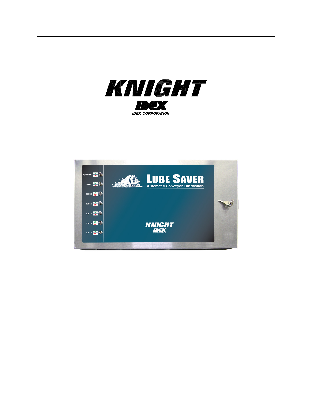
Automatic Zone Lube Signal Wiring
The Lube Saver is designed to accept direct “dry contact”
inputs from an external source (PLC’s, the conveyor controller
etc.) to independently control lubrication for zones 1-6. Simply
connect dry contact inputs to the terminal labeled Zone 1-6
located at the bottom of the power supply panel (as shown to
the left).
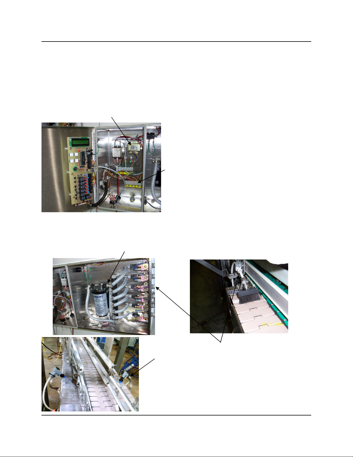
Electric Diaphragm Pump Fluid Connections
(1) Cut a suitable length of 3/8” vinyl reinforced hose (no more than 10 ft. / 3 meters) for suction and push over
barbed connector on right side of the pump securing with a stainless gear clamp. Use a suitable rigid pipe pick
up probe that sinks to the bottom of the chemical container.
(2) Connect suitable length of 3/8” polyethylene tubing from zone
valve connector fittings to brush/jet assemblies located at each
lube point on the conveyor.
(3) Prime the system and check for leaks from the pump all the way
through each lube point. See “Prime System” menu for how to
start/stop pump prime functions.
Page 4 of 12 0900929 Rev: REL (06/08)
 Loading...